Netgear orporated 11200167 N300 WIRELESS ADSL2+ MODEM ROUTER User Manual N300 Wireless ADSL2 Modem Router DGN2200
Netgear Incorporated N300 WIRELESS ADSL2+ MODEM ROUTER N300 Wireless ADSL2 Modem Router DGN2200
Contents
- 1. USERS MANUAL 1
- 2. USERS MANUAL 2
USERS MANUAL 1
350 East Plumeria Drive
San Jose, CA 95134
USA
October 2011
202-10870-01
v1.0
N300 Wireless ADSL2+
Modem Router DGN2200v3
User Manual

2
N300 Wireless ADSL2+ Modem Router DGN2200v3
© 2011 NETGEAR, Inc. All rights reserved
No part of this publication may be reproduced, transmitted, transcribed, stored in a retrieval system, or translated
into any language in any form or by any means without the written permission of NETGEAR, Inc.
Technical Support
Thank you for choosing NETGEAR. To register your product, get the latest product updates, get support online, or
for more information about the topics covered in this manual, visit the Support website at
http://support.netgear.com
Phone (US & Canada only): 1-888-NETGEAR
Phone (Other Countries): Check the list of phone numbers at
http://support.netgear.com/app/answers/detail/a_id/984
Trademarks
NETGEAR, the NETGEAR logo, and Connect with Innovation are trademarks and/or registered trademarks of
NETGEAR, Inc. and/or its subsidiaries in the United States and/or other countries. Information is subject to change
without notice. Other brand and product names are registered trademarks or trademarks of their respective
holders. © 2011 NETGEAR, Inc. All rights reserved.
Statement of Conditions
To improve internal design, operational function, and/or reliability, NETGEAR reserves the right to make changes
to the products described in this document without notice. NETGEAR does not assume any liability that may occur
due to the use, or application of, the product(s) or circuit layout(s) described herein.

Contents | 3
Contents
Chapter 1 Hardware Setup
Unpack Your Modem Router . . . . . . . . . . . . . . . . . . . . . . . . . . . . . . . . . . . . 8
Hardware Features . . . . . . . . . . . . . . . . . . . . . . . . . . . . . . . . . . . . . . . . . . . 8
Label . . . . . . . . . . . . . . . . . . . . . . . . . . . . . . . . . . . . . . . . . . . . . . . . . . . . 8
Back Panel. . . . . . . . . . . . . . . . . . . . . . . . . . . . . . . . . . . . . . . . . . . . . . . . 9
Front Panel . . . . . . . . . . . . . . . . . . . . . . . . . . . . . . . . . . . . . . . . . . . . . . . 9
Modem Router Stand. . . . . . . . . . . . . . . . . . . . . . . . . . . . . . . . . . . . . . . 11
Position Your Modem Router . . . . . . . . . . . . . . . . . . . . . . . . . . . . . . . . . . 12
ADSL Microfilters. . . . . . . . . . . . . . . . . . . . . . . . . . . . . . . . . . . . . . . . . . . . 12
One-Line ADSL Microfilter. . . . . . . . . . . . . . . . . . . . . . . . . . . . . . . . . . . 13
Two-Line ADSL Microfilter. . . . . . . . . . . . . . . . . . . . . . . . . . . . . . . . . . . 13
Summary . . . . . . . . . . . . . . . . . . . . . . . . . . . . . . . . . . . . . . . . . . . . . . . . 13
Cable Your Modem Router . . . . . . . . . . . . . . . . . . . . . . . . . . . . . . . . . . . . 14
Verify the Cabling . . . . . . . . . . . . . . . . . . . . . . . . . . . . . . . . . . . . . . . . . . . 16
Chapter 2 Modem Router Setup
Modem Router Setup Preparation. . . . . . . . . . . . . . . . . . . . . . . . . . . . . . . 18
Use Standard TCP/IP Properties for DHCP . . . . . . . . . . . . . . . . . . . . . 18
Replace an Existing Modem and Router . . . . . . . . . . . . . . . . . . . . . . . . 18
Gather ISP Information . . . . . . . . . . . . . . . . . . . . . . . . . . . . . . . . . . . . . 18
NETGEAR Genie Setup . . . . . . . . . . . . . . . . . . . . . . . . . . . . . . . . . . . . . . 19
View or Change Settings . . . . . . . . . . . . . . . . . . . . . . . . . . . . . . . . . . . . 19
Settings Description. . . . . . . . . . . . . . . . . . . . . . . . . . . . . . . . . . . . . . . . 19
Log In to the Modem Router . . . . . . . . . . . . . . . . . . . . . . . . . . . . . . . . . . . 20
Upgrade Modem Router Firmware . . . . . . . . . . . . . . . . . . . . . . . . . . . . . . 21
Modem Router Interface . . . . . . . . . . . . . . . . . . . . . . . . . . . . . . . . . . . . . . 21
Setup Wizard . . . . . . . . . . . . . . . . . . . . . . . . . . . . . . . . . . . . . . . . . . . . . . . 22
Manual Setup (Basic Settings) . . . . . . . . . . . . . . . . . . . . . . . . . . . . . . . . . 23
ADSL Settings . . . . . . . . . . . . . . . . . . . . . . . . . . . . . . . . . . . . . . . . . . . . . . 26
Unsuccessful Internet Connection. . . . . . . . . . . . . . . . . . . . . . . . . . . . . . . 26
Change Password and Login Time-Out . . . . . . . . . . . . . . . . . . . . . . . . . . 27
Log Out Manually . . . . . . . . . . . . . . . . . . . . . . . . . . . . . . . . . . . . . . . . . . . 28
Types of Logins . . . . . . . . . . . . . . . . . . . . . . . . . . . . . . . . . . . . . . . . . . . . . 28
Chapter 3 Wireless Settings
Wireless Adapter Compatibility . . . . . . . . . . . . . . . . . . . . . . . . . . . . . . . . . 29
Preset Security . . . . . . . . . . . . . . . . . . . . . . . . . . . . . . . . . . . . . . . . . . . . . 30
Security Basics . . . . . . . . . . . . . . . . . . . . . . . . . . . . . . . . . . . . . . . . . . . . . 30

4
N300 Wireless ADSL2+ Modem Router DGN2200v3
Turn Off Wireless Connectivity. . . . . . . . . . . . . . . . . . . . . . . . . . . . . . . . 30
Disable SSID Broadcast. . . . . . . . . . . . . . . . . . . . . . . . . . . . . . . . . . . . . 31
Restrict Access by MAC Address. . . . . . . . . . . . . . . . . . . . . . . . . . . . . . 31
Wireless Security Options . . . . . . . . . . . . . . . . . . . . . . . . . . . . . . . . . . . 31
Add Clients (Computers or Devices) to Your Network . . . . . . . . . . . . . . . . 31
Manual Method. . . . . . . . . . . . . . . . . . . . . . . . . . . . . . . . . . . . . . . . . . . . 32
Wi-Fi Protected Setup (WPS) Method . . . . . . . . . . . . . . . . . . . . . . . . . . 32
Wireless Settings Screen . . . . . . . . . . . . . . . . . . . . . . . . . . . . . . . . . . . . . . 33
Consider Every Device on Your Network . . . . . . . . . . . . . . . . . . . . . . . . 34
View or Change Wireless Settings . . . . . . . . . . . . . . . . . . . . . . . . . . . . . 34
Wireless Settings Screen Fields. . . . . . . . . . . . . . . . . . . . . . . . . . . . . . . 35
Wireless Guest Networks . . . . . . . . . . . . . . . . . . . . . . . . . . . . . . . . . . . . . . 37
Chapter 4 Security Settings
Logs . . . . . . . . . . . . . . . . . . . . . . . . . . . . . . . . . . . . . . . . . . . . . . . . . . . . . . 40
Examples of Log Messages . . . . . . . . . . . . . . . . . . . . . . . . . . . . . . . . . . 41
Keyword Blocking of HTTP Traffic . . . . . . . . . . . . . . . . . . . . . . . . . . . . . . .42
Firewall Rules to Control Network Access . . . . . . . . . . . . . . . . . . . . . . . . .43
Set Up Firewall Rules. . . . . . . . . . . . . . . . . . . . . . . . . . . . . . . . . . . . . . . 43
Port Triggering to Open Incoming Ports. . . . . . . . . . . . . . . . . . . . . . . . . . . 44
Port Forwarding to Permit External Host Communications . . . . . . . . . . . . 45
How Port Forwarding Differs from Port Triggering . . . . . . . . . . . . . . . . . . . 46
Set Up Port Forwarding to Local Servers. . . . . . . . . . . . . . . . . . . . . . . . . . 46
Add a Custom Service . . . . . . . . . . . . . . . . . . . . . . . . . . . . . . . . . . . . . . 47
Edit or Delete a Port Forwarding Entry. . . . . . . . . . . . . . . . . . . . . . . . . . 48
Set Up Port Triggering . . . . . . . . . . . . . . . . . . . . . . . . . . . . . . . . . . . . . . . . 49
Set the Time Zone . . . . . . . . . . . . . . . . . . . . . . . . . . . . . . . . . . . . . . . . . . . 52
Schedule Services . . . . . . . . . . . . . . . . . . . . . . . . . . . . . . . . . . . . . . . . . . . 53
Enable Security Event Email Notification . . . . . . . . . . . . . . . . . . . . . . . . . . 54
Chapter 5 Network Maintenance
Upgrade the Modem Router Firmware. . . . . . . . . . . . . . . . . . . . . . . . . . . . 57
Automatic Firmware Check . . . . . . . . . . . . . . . . . . . . . . . . . . . . . . . . . . 57
Manually Check for Firmware Upgrades . . . . . . . . . . . . . . . . . . . . . . . . . . 58
Back Up and Manage the Configuration File . . . . . . . . . . . . . . . . . . . . . . . 59
View Router Status. . . . . . . . . . . . . . . . . . . . . . . . . . . . . . . . . . . . . . . . . . . 60
Internet Port Settings . . . . . . . . . . . . . . . . . . . . . . . . . . . . . . . . . . . . . . . 61
LAN Port (Local Ports) . . . . . . . . . . . . . . . . . . . . . . . . . . . . . . . . . . . . . . 61
Modem . . . . . . . . . . . . . . . . . . . . . . . . . . . . . . . . . . . . . . . . . . . . . . . . . . 61
Wireless Port . . . . . . . . . . . . . . . . . . . . . . . . . . . . . . . . . . . . . . . . . . . . . 61
Show Statistics . . . . . . . . . . . . . . . . . . . . . . . . . . . . . . . . . . . . . . . . . . . . 62
Connection Status . . . . . . . . . . . . . . . . . . . . . . . . . . . . . . . . . . . . . . . . . 63
View Attached Devices. . . . . . . . . . . . . . . . . . . . . . . . . . . . . . . . . . . . . . . . 63
Run Diagnostic Utilities . . . . . . . . . . . . . . . . . . . . . . . . . . . . . . . . . . . . . . .64

5
N300 Wireless ADSL2+ Modem Router DGN2200v3
Chapter 6 USB Storage
USB Drive Requirements . . . . . . . . . . . . . . . . . . . . . . . . . . . . . . . . . . . . . .66
ReadySHARE Access . . . . . . . . . . . . . . . . . . . . . . . . . . . . . . . . . . . . . . . .66
File-Sharing Scenarios . . . . . . . . . . . . . . . . . . . . . . . . . . . . . . . . . . . . . . . .67
USB Storage Basic Settings. . . . . . . . . . . . . . . . . . . . . . . . . . . . . . . . . . . .68
Edit a Network Folder . . . . . . . . . . . . . . . . . . . . . . . . . . . . . . . . . . . . . . . . .70
USB Storage Advanced Settings . . . . . . . . . . . . . . . . . . . . . . . . . . . . . . . .71
Create a Network Folder. . . . . . . . . . . . . . . . . . . . . . . . . . . . . . . . . . . . .72
Safely Remove USB Drive . . . . . . . . . . . . . . . . . . . . . . . . . . . . . . . . . . . . .73
Media Server Settings . . . . . . . . . . . . . . . . . . . . . . . . . . . . . . . . . . . . . . . .73
Approved USB Devices (Advanced USB Settings) . . . . . . . . . . . . . . . . . .74
Connect to the USB Drive from a Remote Computer. . . . . . . . . . . . . . . . .74
Connect to the USB Drive with Microsoft Network Settings . . . . . . . . . . . .75
Enabling File and Printer Sharing. . . . . . . . . . . . . . . . . . . . . . . . . . . . . .75
Chapter 7 Advanced Settings
WAN Setup. . . . . . . . . . . . . . . . . . . . . . . . . . . . . . . . . . . . . . . . . . . . . . . . .78
Default DMZ Server . . . . . . . . . . . . . . . . . . . . . . . . . . . . . . . . . . . . . . . .79
Dynamic DNS . . . . . . . . . . . . . . . . . . . . . . . . . . . . . . . . . . . . . . . . . . . . . . .80
LAN Setup . . . . . . . . . . . . . . . . . . . . . . . . . . . . . . . . . . . . . . . . . . . . . . . . .81
LAN Setup Screen Settings . . . . . . . . . . . . . . . . . . . . . . . . . . . . . . . . . .81
IP Address Reservation . . . . . . . . . . . . . . . . . . . . . . . . . . . . . . . . . . . . .82
Quality of Service (QoS). . . . . . . . . . . . . . . . . . . . . . . . . . . . . . . . . . . . . . .83
Advanced Wireless Settings. . . . . . . . . . . . . . . . . . . . . . . . . . . . . . . . . . . .84
Advanced Wireless Settings. . . . . . . . . . . . . . . . . . . . . . . . . . . . . . . . . .84
WPS Settings . . . . . . . . . . . . . . . . . . . . . . . . . . . . . . . . . . . . . . . . . . . . .85
Wireless Card Access List . . . . . . . . . . . . . . . . . . . . . . . . . . . . . . . . . . .85
Remote Management . . . . . . . . . . . . . . . . . . . . . . . . . . . . . . . . . . . . . . . . .87
Static Routes . . . . . . . . . . . . . . . . . . . . . . . . . . . . . . . . . . . . . . . . . . . . . . .88
Static Route Example . . . . . . . . . . . . . . . . . . . . . . . . . . . . . . . . . . . . . . .88
Universal Plug and Play . . . . . . . . . . . . . . . . . . . . . . . . . . . . . . . . . . . . . . .90
Traffic Meter . . . . . . . . . . . . . . . . . . . . . . . . . . . . . . . . . . . . . . . . . . . . . . . .91
Wireless Bridging and Repeating Networks . . . . . . . . . . . . . . . . . . . . . . . .92
Set Up a Point-to-Point Bridge . . . . . . . . . . . . . . . . . . . . . . . . . . . . . . . .94
Set Up a Multi-Point Bridge . . . . . . . . . . . . . . . . . . . . . . . . . . . . . . . . . .95
Repeater with Wireless Client Association . . . . . . . . . . . . . . . . . . . . . . .96
Change the Device Mode . . . . . . . . . . . . . . . . . . . . . . . . . . . . . . . . . . . . . .98
Chapter 8 Troubleshooting
Troubleshooting with the LEDs. . . . . . . . . . . . . . . . . . . . . . . . . . . . . . . . .100
Power LED Is Off . . . . . . . . . . . . . . . . . . . . . . . . . . . . . . . . . . . . . . . . .100
Power LED Is Red . . . . . . . . . . . . . . . . . . . . . . . . . . . . . . . . . . . . . . . .100
LAN LED Is Off . . . . . . . . . . . . . . . . . . . . . . . . . . . . . . . . . . . . . . . . . . .101
Cannot Log In to the Wireless-N Modem Router . . . . . . . . . . . . . . . . . . .101
Troubleshooting the Internet Connection . . . . . . . . . . . . . . . . . . . . . . . . .102
ADSL Link. . . . . . . . . . . . . . . . . . . . . . . . . . . . . . . . . . . . . . . . . . . . . . .102

6
N300 Wireless ADSL2+ Modem Router DGN2200v3
Internet LED Is Red . . . . . . . . . . . . . . . . . . . . . . . . . . . . . . . . . . . . . . . 103
Obtaining an Internet IP Address . . . . . . . . . . . . . . . . . . . . . . . . . . . . . 103
Troubleshooting PPPoE or PPPoA . . . . . . . . . . . . . . . . . . . . . . . . . . . 103
Troubleshooting Internet Browsing. . . . . . . . . . . . . . . . . . . . . . . . . . . . 104
TCP/IP Network Not Responding. . . . . . . . . . . . . . . . . . . . . . . . . . . . . . . 104
Test the LAN Path to Your Modem Router. . . . . . . . . . . . . . . . . . . . . . 104
Test the Path from Your Computer to a Remote Device . . . . . . . . . . . 105
Cannot Log in . . . . . . . . . . . . . . . . . . . . . . . . . . . . . . . . . . . . . . . . . . . . . . 106
Changes Not Saved . . . . . . . . . . . . . . . . . . . . . . . . . . . . . . . . . . . . . . . . . 106
Incorrect Date or Time . . . . . . . . . . . . . . . . . . . . . . . . . . . . . . . . . . . . . . . 107
Appendix A Supplemental Information
Factory Settings . . . . . . . . . . . . . . . . . . . . . . . . . . . . . . . . . . . . . . . . . . . .109
Specifications . . . . . . . . . . . . . . . . . . . . . . . . . . . . . . . . . . . . . . . . . . . . . . 111
Appendix B Notification of Compliance
Index

7
1
1. Hardware Setup
Getting to know your modem router
The N300 Wireless ADSL2+ Modem Router DGN2200v3 provides you with an easy and secure
way to set up a wireless home network with fast access to the Internet over a high-speed digital
subscriber line (DSL). It has a built-in DSL modem, is compatible with all major DSL Internet
service providers, lets you block unsafe Internet content and applications, and protects the
devices (PCs, gaming consoles, and so on) that you connect to your home network.
For more information on the topics covered in this manual, visit the Support website at
http://support.netgear.com.
If you want instructions about how to wall-mount your router, see Wall-Mount Your Router at
http://support.netgear.com/app/answers/detail/a_id/18725.
If you have not already set up your new modem router using the installation guide that comes in
the box, this chapter walks you through the hardware setup. Chapter 2, Modem Router Setup,
explains how to set up your Internet connection.
This chapter contains the following sections:
• Unpack Your Modem Router
• Hardware Features
• Position Your Modem Router
• ADSL Microfilters
• Cable Your Modem Router
• Verify the Cabling
Hardware Setup
8
N300 Wireless ADSL2+ Modem Router DGN2200v3
Unpack Your Modem Router
Your box should contain the following items:
• N300 Wireless ADSL2+ Modem Router DGN2200v3
• AC power adapter (plug varies by region)
• Category 5 (Cat 5) Ethernet cable
• Telephone cable with RJ-11 connector
• Microfilters and splitters (quantity and type vary by region)
• Resource CD with NETGEAR Genie setup
• Installation guide with cabling and modem router setup instructions
If any parts are incorrect, missing, or damaged, contact your NETGEAR dealer. Keep the
carton and original packing materials, in case you need to return the product for repair.
Hardware Features
Before you cable your modem router, take a moment to become familiar with the label and
the front and back panels. Pay particular attention to the LEDs on the front panel.
Label
The label on the bottom of the modem router shows the Restore Factory Settings button,
security PIN, preset login information, MAC address, and serial number.
Wi-Fi network name MAC address
Serial
WPS
Restore
and password
Factory
S
ettings number
security
PIN
Figure 1. Label on modem router bottom
See Preset Security on page 30 for information about preset security and MAC addresses.
See Factory Settings on page 109 for information about restoring factory settings.
Hardware Setup
9
N300 Wireless ADSL2+ Modem Router DGN2200v3
Back Panel
The back panel has the On/Off button and port connections as shown in the figure.
ADSL
Ethernet LAN
USB
On/Off
Power
Figure 2. Back panel port connections
Front Panel
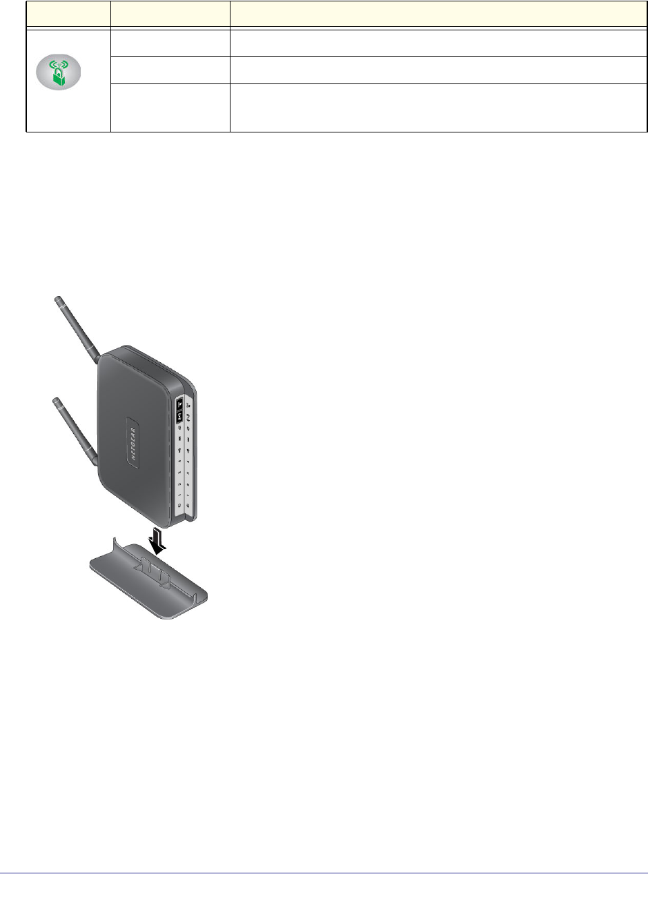
The modem router front panel has the status LEDs and icons shown in the figure. Note that
the Wireless and WPS icons are buttons.
Power LAN Ports (1-4) USB DSL Wireless WPSInternet
Figure 3. Front panel LEDs and icons
The following table describes the LEDs, icons, and buttons on the front panel from left to
right.
Hardware Setup
10
N300 Wireless ADSL2+ Modem Router DGN2200v3
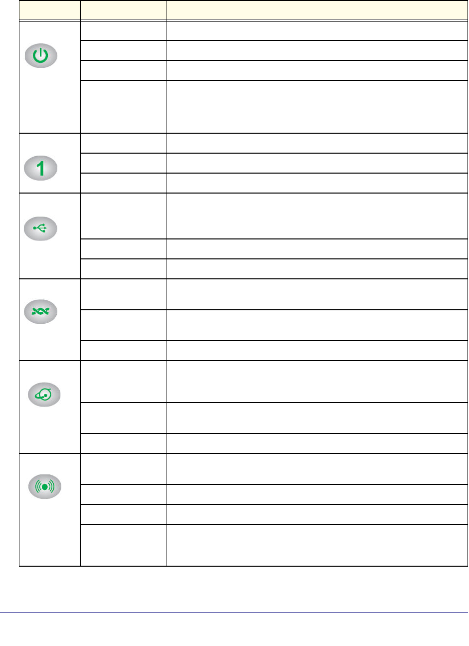
Table 1. Front Panel LEDs
Icon LED Activity Description
Power Solid green Power is supplied to the modem router.
Solid red POST (power-on self-test) failure or a device malfunction has occurred.
Off Power is not supplied to the modem router.
Restore factory
settings
The LED blinks momentarily when the Restore Factory Settings button on
the bottom of the unit is pressed for 6 seconds. The Power LED then blinks
red three times when the Restore Factory Settings button is released and
then turns green as the gateway resets to the factory defaults.
LAN Solid green The LAN port has detected an Ethernet link with a device.
Blinking green Data is being transmitted or received.
Off No link is detected on this port.
USB Off • No USB device connected.
• “Safely Remove Hardware” has been activated.
• An error has occurred with the device.
Solid green USB device is ready to use.
Blinking green USB device is in use.
DSL Solid green You have a DSL connection. In technical terms, the DSL port is
synchronized with an ISP’s network-access device.
Blinking green Indicates that the modem router is negotiating the best possible speed on
the DSL line.
Off The unit is off or there is no IP connection.
Internet Solid green You have an Internet connection. If this connection is dropped due to an
idle time-out but the DSL connection is still present, the light stays green. If
the Internet connection is dropped for any other reason, the light turns off.
Solid red The Internet (IP) connection failed. See Troubleshooting the Internet
Connection on page 102 for troubleshooting information.
Blinking green Data is being transmitted over the DSL port.
Wireless
Icon is on the
Wireless
button
Off No Internet connection is detected or the device is in bridge mode (an
external device handles the ISP connection).
Solid green There is wireless connectivity.
Blinking green Data is being transmitted or received over the wireless link.
Off There is no wireless connectivity. You can still plug an Ethernet cable into
one of the LAN ports to get wired connectivity. See Turn Off Wireless
Connectivity on page 30 for more information about the use of this button.
Hardware Setup
11
N300 Wireless ADSL2+ Modem Router DGN2200v3
Modem Router Stand
For optimal wireless network performance, use the stand (included in the package) to
position your modem router upright.
1. Orient your modem router vertically.
2. Insert the tabs of the stand into the slots on the bottom of your modem router as shown.
3. Place your modem router in a suitable area for installation (near an AC power outlet and
accessible to the Ethernet cables for your wired computers).
WPS
Icon is on the
WPS button
Solid green Indicates that wireless security has been enabled.
Blinking green WPS-capable device is connecting to the device.
Off WPS is not enabled. See Wi-Fi Protected Setup (WPS) Method on page 32
for more information about the use of this button.
Table 1. Front Panel LEDs (continued)
Icon LED Activity Description

Hardware Setup
12
N300 Wireless ADSL2+ Modem Router DGN2200v3
Position Your Modem Router
The modem router lets you access your network from virtually anywhere within the operating
range of your wireless network. However, the operating distance or range of your wireless
connection can vary significantly depending on the physical placement of your modem router.
For example, the thickness and number of walls the wireless signal passes through can limit
the range. For best results, place your modem router:
• Near the center of the area where your computers and other devices operate, and
preferably within line of sight to your wireless devices.
• So it is accessible to an AC power outlet and near Ethernet cables for wired computers.
• In an elevated location such as a high shelf, keeping the number of walls and ceilings
between the modem router and your other devices to a minimum.
• Away from electrical devices that are potential sources of interference, such as ceiling
fans, home security systems, microwaves, PCs, or the base of a cordless phone or 2.4
GHz cordless phone.
• Away from any large metal surfaces, such as a solid metal door or aluminum studs. Large
expanses of other materials such as glass, insulated walls, fish tanks, mirrors, brick, and
concrete can also affect your wireless signal.
• With the antennas in a vertical position to provide the best side-to-side coverage or in a
horizontal position to provide the best up-and-down coverage, as applicable.
When you use multiple access points, it is better if adjacent access points use different radio
frequency channels to reduce interference. The recommended channel spacing between
adjacent access points is 5 channels (for example, use Channels 1 and 6, or 6 and 11).
ADSL Microfilters
If this is the first time you have cabled a router between a DSL phone line and your computer
or laptop, you might not be familiar with ADSL microfilters. If you are, you can skip this
section and proceed to Cable Your Modem Router on page 14.
An ADSL microfilter is a small in-line device that filters DSL interference out of standard
phone equipment that shares the same line with your DSL service. Every telephone device
that connects to a telephone line that provides DSL service needs an ADSL microfilter to filter
out the DSL interference. Example devices are telephones, fax machines, answering
machines, and caller ID displays. Note that not every phone line in your home necessarily
carries DSL service. That depends on the DSL service setup in your home.
Note: Often the ADSL microfilter is in the box with the modem router. If
you purchased the modem router in a country where a microfilter is
not included, you have to acquire the ADSL microfilter separately.
Hardware Setup
13
N300 Wireless ADSL2+ Modem Router DGN2200v3
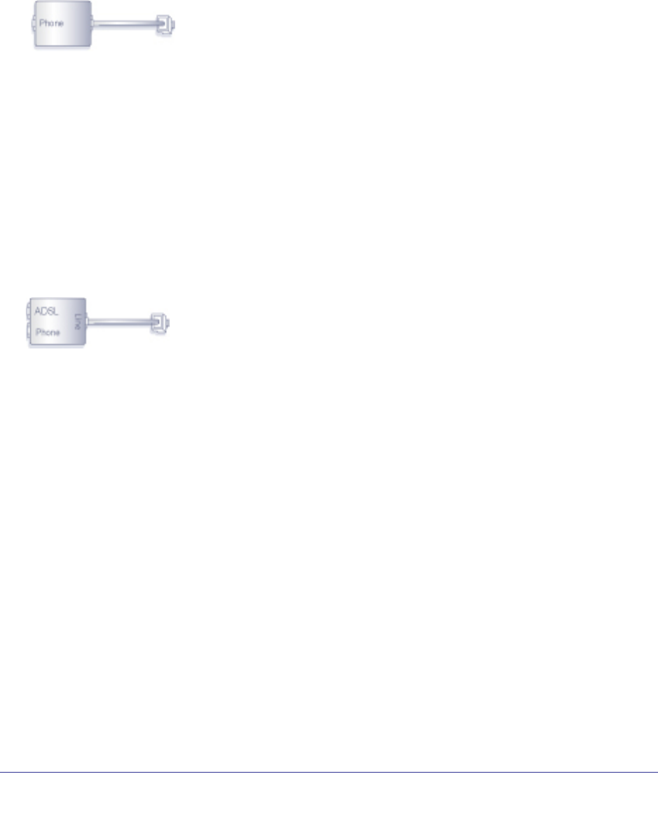
One-Line ADSL Microfilter
Plug the ADSL microfilter into the wall outlet and plug your phone equipment into the jack
labeled Phone. The modem router plugs directly into a separate DSL line. Plugging the
modem router into the phone jack blocks the Internet connection. If you do not have a
separate DSL line for the modem router, the best thing to do is to use an ADSL microfilter
with a built-in splitter (see Two-Line ADSL Microfilter )
Plugs into DSL line
.
Figure 4. One-line ADSL microfilter
If you do not have a separate DSL line for the modem router, the second-best solution is to
get a separate splitter. To use a one-line filter with a separate splitter, insert the splitter into
the phone outlet, connect the one-line filter to the splitter, and connect the phone to the filter.
Two-Line ADSL Microfilter
Use an ADSL microfilter with a built-in splitter when there is a single wall outlet that provides
connectivity for both the modem router and your telephone equipment. Plug the ADSL
microfilter into the wall outlet, plug your phone equipment into the jack labeled Phone, and
plug the modem router into the jack labeled ADSL.
Plugs into the DSL line
Figure 5. Two-line ADSL microfilter with built-in splitter
Summary
• One-line ADSL microfilter. Use with a phone or fax machine.
• Splitter. Use with a one-line ADSL microfilter to share an outlet with a phone and the
modem router.
• Two-line ADSL microfilter with built-in splitter. Use to share an outlet with a phone and the
modem router.
Hardware Setup
14
N300 Wireless ADSL2+ Modem Router DGN2200v3
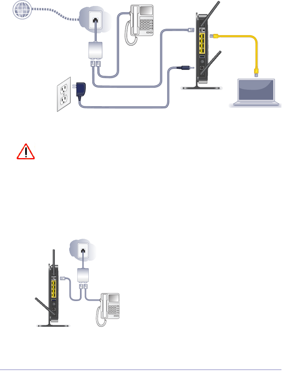
Cable Your Modem Router
Internet
ADSL
Phone
Line
Figure 6. Cable connections
CAUTION:
Incorrectly connecting a filter to your modem router blocks your DSL
connection.
This section includes the same information on the printed installation guide that came with
the modem router.
To cable the modem router:
1. Connect the ADSL.
a.
ADSL
Phone
Line
1
Install an ADSL microfilter between the phone line and the phone.
b. Connect the ADSL port of the modem router to the ADSL port of the microfilter
c. Use an ADSL microfilter for every phone line in the house if your modem router and
telephone connect to the same phone line.
Hardware Setup
15
N300 Wireless ADSL2+ Modem Router DGN2200v3
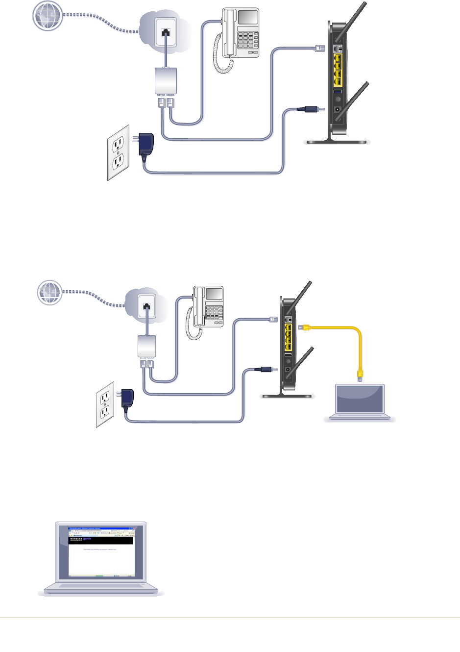
2. Add power to the modem router.
Internet
ADSL
Phone
Line
2
a. Connect the power adapter to the router and plug the power adapter into an outlet.
b. Wait for the WiFi LED on the front panel to turn on. If none of the LEDs on the front
panel are on, press the Power On/Off button on the rear panel of the modem router.
3. Connect a computer.
You can use an Ethernet cable or connect wirelessly.
Internet
ADSL
Phone
Line
3
• Use the yellow Ethernet cable to connect your computer to an Ethernet port on your
router.
• Or, connect wirelessly by using the preset wireless security settings located on the
label on the bottom of the router.
4. Open a browser.
4

Hardware Setup
16
N300 Wireless ADSL2+ Modem Router DGN2200v3
If a web page does not open, close and reopen the browser and enter http://routerlogin.net
in the address bar.
5. Connect any additional wired PCs to your modem router by inserting an Ethernet cable from
a PC into one of the three remaining LAN ports.
Note: If you are an advanced user who wants to set up the modem to run
in “pure bridge” or Modem mode, you need to log in to the modem
and change the Device Mode setting to Modem mode. See Change
the Device Mode on page 98.
Verify the Cabling
Verify that your modem router is cabled correctly by checking the modem router LEDs. Turn
on the modem router by pressing the On/Off button on the back.
• The Power LED is green when the modem routeris turned on.
• The LAN ports are green for each PC cabled to the modem router by an Ethernet
cable.
• The wireless LED is green when the modem router is turned on.
• The DSL LED is green when you have a DSL connection.
• The Internet LED is red when there is no Internet connection.
Turn on your computer. If software usually logs you in to your Internet connection, do not run
that software. Cancel it if it starts automatically.
Verify that the LAN LEDs (1 through 4) are lit for any computers cabled to the modem
router by an Ethernet cable.

17
2
2. Modem Router Setup
This chapter explains how to set up your Internet connection using one of three methods:
NETGEAR Genie®, Setup Wizard, or manual setup. If you have already set up your modem
router using one of these methods, the initial setup is complete. Refer to this chapter if you want
to become familiar with the modem router menus, view or adjust the initial settings, or change
the modem router password and login time-out.
This chapter contains the following sections:
• Modem Router Setup Preparation
• NETGEAR Genie Setup
• Log In to the Modem Router
• Upgrade Modem Router Firmware
• Modem Router Interface
• Setup Wizard
• Manual Setup (Basic Settings)
• ADSL Settings
• Unsuccessful Internet Connection
• Change Password and Login Time-Out
• Log Out Manually
• Types of Logins

Modem Router Setup
18
N300 Wireless ADSL2+ Modem Router DGN2200v3
Modem Router Setup Preparation
You can set up your modem router with the NETGEAR Genie as described in NETGEAR
Genie Setup on page 19, with the Setup Wizard as described in Setup Wizard on page 22, or
manually as described in Manual Setup (Basic Settings) on page 23. However, before you
start the setup process, you need to have your ISP information and to make sure the laptops,
PCs, and other devices in the network have the settings described here.
Note: For a Macintosh or Linux system, you have to use manual setup.
Use Standard TCP/IP Properties for DHCP
If you set up your computer to use a static IP address, you have to change the settings back
so that it uses Dynamic Host Configuration Protocol (DHCP).
Replace an Existing Modem and Router
To replace an existing modem and router, disconnect them and set them aside before starting
the modem router setup.
Gather ISP Information
You need the following information to set up your modem router and to check that your
Internet configuration is correct. Your Internet service provider (ISP) should have provided
you with all the information needed to connect to the Internet. If you cannot locate this
information, ask your ISP to provide it. When your modem router Internet connection is set
up, you no longer need to launch the ISP’s login program on your computer to access the
Internet. When you start an Internet application, your modem router automatically logs you in.
• Active Internet service provided by a DSL account
• The ISP configuration information for your DSL account
-ISP login name and password
-ISP Domain Name Server (DNS) addresses
-Fixed or static IP address
-Host and domain names
-Depending on how your ISP set up your Internet account, you could need to know
one or more of these settings for a manual setup:
- Virtual path identifier (VPI) and virtual channel identifier (VCI) parameters
- Multiplexing method
- Host and domain names

Modem Router Setup
19
N300 Wireless ADSL2+ Modem Router DGN2200v3
NETGEAR Genie Setup
NETGEAR Genie is on the Resource CD and runs on a PC with Microsoft Windows 7,
Windows Vista, Windows XP, or Windows 2000 with Service Pack 2 or later. It is the easiest
way to set up the modem router because it automates many steps and verifies that those
steps have been successfully completed. It takes about 15 minutes to complete.
Before running NETGEAR Genie on a corporate PC, check with your company’s network
support staff. Corporate network settings or virtual private network (VPN) client software
might conflict with your modem router settings. To avoid a conflict, use another PC.
1. Locate the DSL settings information (user name and password) provided by your ISP.
Contact your ISP if you do not have it.
2. Insert the Resource CD into your Windows PC. The CD starts and detects the language you
are using on your PC. Select a different language option, if you prefer.
If the CD does not start, go to the CD drive (under My Computer on Windows), browse
the CD, and double-click .
3. When the Welcome screen displays, click Setup to start the genie. Follow the instructions to
complete the setup. NETGEAR Genie checks your hardware setup and guides you through
connecting the modem router to the Internet and adding computers to your network.
Your modem router connects to the Internet when any computer on your network
launches a Web browser to access the Internet. The modem router’s Internet LED
blinks.
View or Change Settings
You can view and change the settings in the following ways:
• Log in to your modem router. To do this you can click the shortcut that was placed
on your desktop during the NETGEAR Genie setup, or use an Internet browser. See Log
In to the Modem Router on page 20.
• Open the Router_Setup.html file that was placed on your desktop during the NETGEAR
Genie setup. This file has setup and system information, the NETGEAR Technical
Support phone number, links to the NETGEAR website, and a modem router login link.
Settings Description
When the NETGEAR Genie is done, your modem router has the following settings. Some of
these can be viewed in Router_Setup.html.
• Language and country as described in Setup Wizard on page 22.
• Internet connection settings as described in Manual Setup (Basic Settings) on page 23.
• Network settings. The NETGEAR Genie steps you through connecting from your
computer to the modem router.
Modem Router Setup
20
N300 Wireless ADSL2+ Modem Router DGN2200v3
Log In to the Modem Router
You can log in to the modem router to view or change settings or to set up the modem router.
To log in:
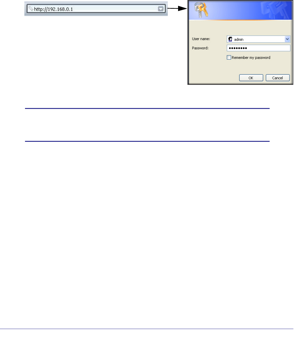
1. Type http://192.168.0.1 in the address field of your browser and press Enter to display
the login window. You can also enter either of these addresses to access the modem
router: http://www.routerlogin.net or http://www.routerlogin.com.
2. Enter admin for the user name and password for the password, both in lowercase letters.
Note: The modem router user name and password are probably different
from the user name and password for logging in to your Internet
connection. See Types of Logins on page 28 for more information.
The modem router screen displays as described in Modem Router Interface on page 21.
If you do not see the login prompt:
1. Check the LEDs on the modem router front panel to make sure that the modem router is
plugged into an electrical outlet, its power is on, and the Ethernet cable between your
computer and the modem router is connected to a LAN port.
2. If you connected the Ethernet cable and quickly launched your browser and typed in the
modem router URL, your computer might need a minute or two to recognize the LAN
connection. Relaunch your browser and try again.
3. If you are having trouble accessing the modem router wirelessly, NETGEAR recommends
that during setup you use an Ethernet cable to connect your computer so that you can log in
to the modem router.
4. If you cannot connect to the modem router, check the Internet Protocol (TCP/IP) properties
in the Network Connections section of your PC Control Panel. They should be set to obtain
both IP and DNS server addresses automatically. See your computer documentation.
Modem Router Setup
21
N300 Wireless ADSL2+ Modem Router DGN2200v3
Upgrade Modem Router Firmware
When you log in, if you are connected to the Internet, the Firmware Upgrade Assistant screen
displays so you can upgrade to the latest firmware. See Chapter 5, Network Maintenance, for
more information about upgrading firmware.
To upgrade the firmware:
1. Click Yes to check for new firmware (recommended). The modem router checks the
NETGEAR database for new firmware.
2. If no new firmware is available, click No to exit. You can check for new firmware later.
3. If new firmware is available, click Yes to upgrade the modem router with the latest firmware.
After the upgrade, the modem router restarts.
CAUTION:
Do not try to go online, turn off the modem router, shut down the computer,
or do anything else to the modem router until the modem router finishes
restarting and the Ready light has stopped blinking for several seconds.
You cannot upgrade firmware until you have established your Internet connection as
described in Setup Wizard on page 22.
Modem Router Interface
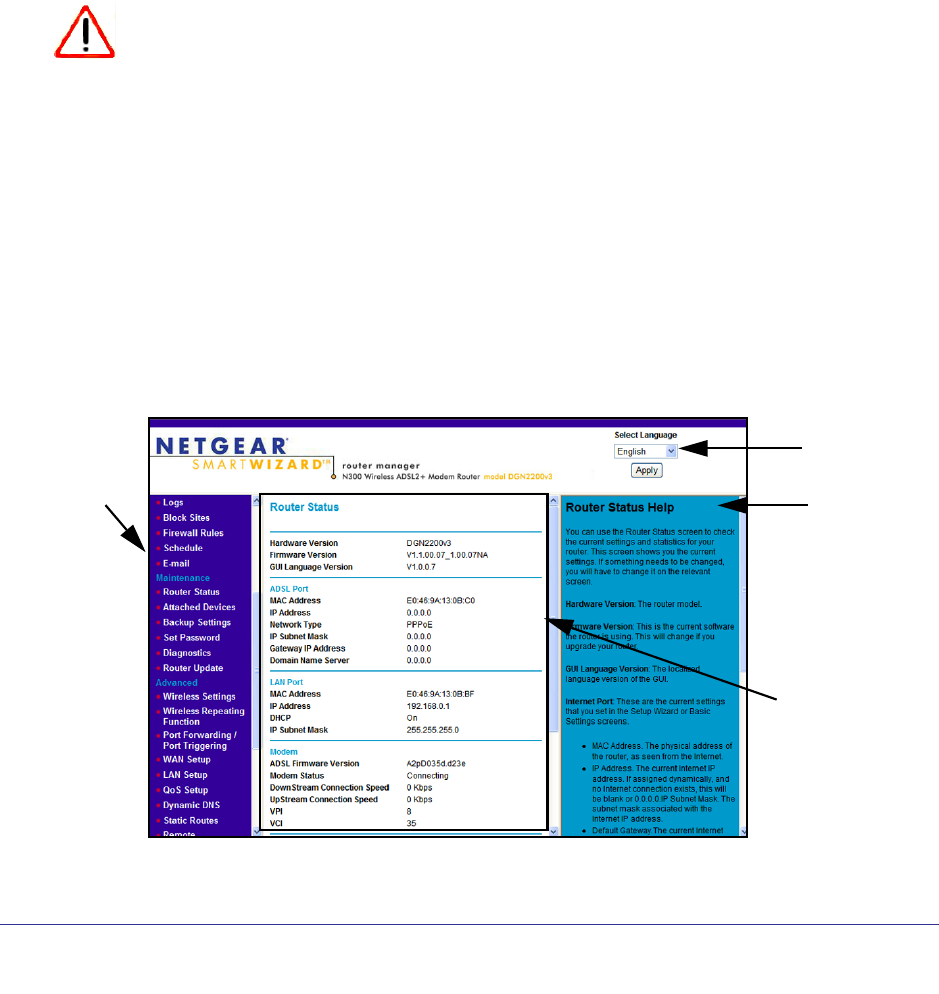
The modem router interface lets you view or change the modem router settings. The left
column has menus, and the right column provides online help. The middle column is the
screen for the current menu option.
Help for
the current
Screen selected
Menus
Language
from the menu
(scroll
down to
view
more)
screen
Figure 7. Modem Router interface
Modem Router Setup
22
N300 Wireless ADSL2+ Modem Router DGN2200v3
Note: If you go to the Advanced Device Mode screen and change the
device mode setting to Modem Mode, then menu items not
supported in Modem Mode will be grayed out.
• Setup Wizard. Specify the language and location, and automatically detect the Internet
connection. See Setup Wizard on page 22.
• Add WPS Client. Add WPS-compatible wireless devices and other equipment to your
wireless network. See Add Clients (Computers or Devices) to Your Network on page 31.
• Setup menu. Set, upgrade, and check the ISP and wireless network settings of your
modem router. See Manual Setup (Basic Settings) on page 23 and ADSL Settings on
page 26. See also Chapter 3, Wireless Settings, for information about preset and basic
security settings.
• Content Filtering menu. View and configure the modem router firewall settings to
prevent objectionable content from reaching your PCs. See Chapter 4, Security Settings.
• Maintenance menu. Administer and maintain your modem router and network. See
Chapter 5, Network Maintenance.
• Advanced menu. Set the modem router up for unique situations such as when remote
access by IP or by domain name from the Internet is needed. See Chapter 7, Advanced
Settings. Using this menu requires a solid understanding of networking concepts.
• Web Support. Go to the NETGEAR support site to get information, help, and product
documentation. These links work once you have an Internet connection.
Setup Wizard
If you do not use the NETGEAR Genie, you have to log in to the modem router to set the
country, language, and Internet connection. If you performed the NETGEAR Genie setup, the
country, language, Internet, and wireless network settings are already configured.
To use the Setup Wizard:
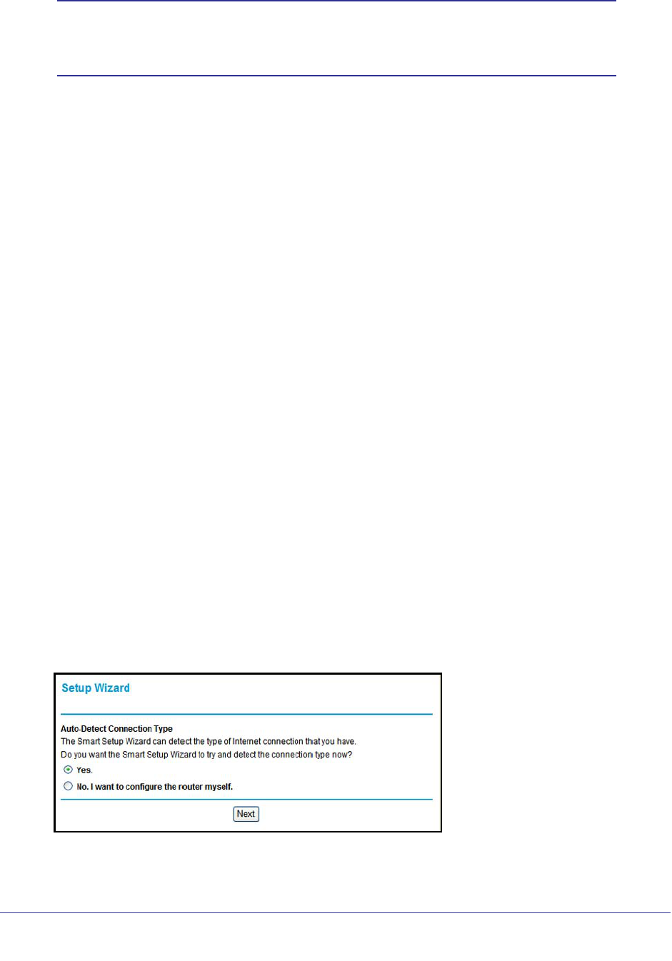
1. From the top of the modem router menu, select Setup Wizard to display the following
screen:
2. Select either Yes or No, I want to configure the Router myself. If you select No, proceed
to Manual Setup (Basic Settings) on page 23.

Modem Router Setup
23
N300 Wireless ADSL2+ Modem Router DGN2200v3
3. If you selected Yes, click Next.
With automatic Internet detection, the Setup Wizard searches your Internet connection
for servers and protocols to determine your ISP configuration.
Note: The Setup Wizard cannot detect a Point-to-Point Tunneling Protocol
(PPTP) connection. If your ISP uses PPTP, you have to set your
Internet connection through the screen described in Manual Setup
(Basic Settings) on page 23.
Manual Setup (Basic Settings)
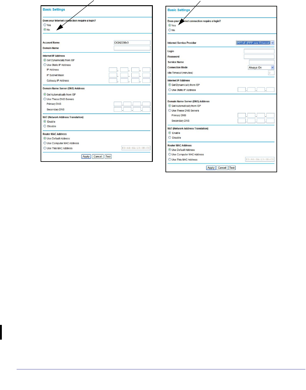
The Basic Settings screen displays when you select No. I want to configure the Router
myself in the Setup Wizard and is also available from the modem router menu. It is where
you view or change ISP information. The fields that display vary depending on whether or not
your Internet connection requires a login.
To use Basic Settings to specify your Internet settings manually:
Note: Check that the country is set as described Setup Wizard on page 22
before proceeding with the manual setup.
1. Select Set Up > Basic Settings, and select Yes or No depending on whether or not
your ISP requires a login. Figure , The following descriptions explain all of the possible
fields in the Basic Settings screen. Note that which fields appear in this screen depends
on whether or not an ISP login is required. shows both forms of the Basic Settings
screen.
• Yes. Select the encapsulation method and enter the login name. If you want to
change the login time-out, enter a new value in minutes.
• No. Enter the account and domain names, as needed.
2. Enter the settings for the IP address and DNS server. The default DSL settings usually work
fine. If you have problems with your connection, check the DSL settings, and see ADSL
Settings on page 26 for more information.
3. If no login is required, you can specify the MAC Address setting.
4. Click Apply to save your settings.
Modem Router Setup
24
N300 Wireless ADSL2+ Modem Router DGN2200v3
5. Click Test to test your Internet connection. If the NETGEAR website does not appear within
1 minute, and see Troubleshooting on page 99.
ISP does not require login ISP does require login
The following descriptions explain all of the possible fields in the Basic Settings screen. Note
that which fields appear in this screen depends on whether or not an ISP login is required.
Does Your ISP Require a Login? Answer either yes or no.
• When no login is required, these fields display:
Account Name (If required). Enter the account name provided by your ISP. This might
also be called the host name.
Domain Name (If required). Enter the domain name provided by your ISP.
• When your ISP requires a login, these fields display:
Encapsulation. Encapsulation is a method for enclosing multiple protocols. PPP stands
for Point-to-Point Protocol. The choices are PPPoE (PPP over Ethernet) or PPPoA (PPP
over ATM).
Login. The login name provided by your ISP. This is often an email address.
Password. The password that you use to log in to your ISP.
Connection Mode. Specify whether your Internet connection is always on, or is off by
default unless you are using it.

Modem Router Setup
25
N300 Wireless ADSL2+ Modem Router DGN2200v3
Idle Timeout (In minutes). If you want to change the login timeout, enter a new value in
minutes. This determines how long the modem router keeps the Internet connection
active after there is no Internet activity from the LAN. Entering a value of 0 (zero) means
never log out.
Internet IP Address.
• When a login is required, these fields display:
Get Dynamically from ISP. Your ISP uses DHCP to assign your IP address. Your ISP
automatically assigns these addresses.
Use Static IP Address. Enter the IP address, IP subnet mask, and the gateway IP
address that your ISP assigned. The gateway is the ISP’s modem router to which your
modem router will connect.
• When a login is not required, this field displays:
Use IP Over ATM (IPoA). Your ISP uses classical IP addresses (RFC 1577). Enter the IP
address, IP subnet mask, and gateway IP addresses that your ISP assigned.
Domain Name Server (DNS) Address. The DNS server is used to look up site addresses
based on their names.
• Get Automatically from ISP. Your ISP uses DHCP to assign your DNS servers. Your ISP
automatically assigns this address.
• Use These DNS Servers. If you know that your ISP does not automatically transmit DNS
addresses to the modem router during login, select this option, and enter the IP address
of your ISP’s primary DNS server. If a secondary DNS server address is available, enter it
also.
NAT (Network Address Translation). NAT automatically assigns private IP addresses
(10.1.1.x) to LAN-connected devices.
• Enable. Usually NAT is enabled.
• Disable. This disables NAT, but leaves the firewall active. Disable NAT only if you are
sure you do not need it. When NAT is disabled, only standard routing is performed by this
modem. Classical routing lets you directly manage the IP addresses that the modem
router uses. Classical routing should be selected only by experienced users.1
• Disable firewall. This disables the firewall in addition to disabling NAT. With the firewall
disabled, the protections usually provided to your network are disabled.
When no login is required, this field displays:
Router MAC Address. The Ethernet MAC address used by the modem router on the
Internet port. Some ISPs register the MAC address of the network interface card in your
computer when your account is first opened. They will then accept traffic only from the MAC
address of that computer. This feature allows your modem router to use your computer’s
MAC address (this is also called cloning).
1. Disabling NAT reboots the modem router and resets its configuration settings to the factory defaults. Disable NAT
only if you plan to set up the modem router in a setting where you will be manually administering the IP address space
on the LAN side of the modem.
Modem Router Setup
26
N300 Wireless ADSL2+ Modem Router DGN2200v3
• Use Default Address. Use the default MAC address.
• Use Computer MAC Address. The modem router will capture and use the MAC address
of the computer that you are now using. You must be using the one computer that is
allowed by the ISP.
• Use This MAC Address. Enter the MAC address that you want to use.
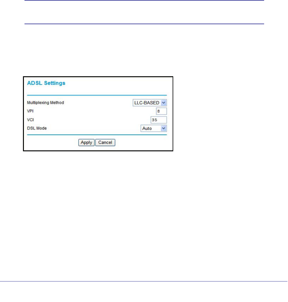
ADSL Settings
DSL settings of your modem router work fine for most ISPs. However, some ISPs use a
multiplexing method and virtual circuit number for the virtual path identifier (VPI) and virtual
channel identifier (VCI).
Note: You have to use the Setup Wizard to select the correct country for
the default DSL settings to work.
To manually specify the ADSL settings:
If your ISP provided you with a multiplexing method or VPI/VCI number, enter the setting:
1. Select Setup > ADSL Settings to display the following screen:
2. In the Multiplexing Method drop-down list, select LLC-based or VC-based.
3. For the VPI, type a number between 0 and 255. The default is 8 for the U.S. version, 0 for
the world wide version, and 1 for the German version.
4. For the VCI, type a number between 32 and 65535. The default is 35 for the U.S. version,
38 for the worldwide version, and 32 for the German version.
5. Click Apply.
Unsuccessful Internet Connection
1. Review your settings to be sure that you have selected the correct options and typed
everything correctly.
2. Contact your ISP to verify that you have the correct configuration information.
Modem Router Setup
27
N300 Wireless ADSL2+ Modem Router DGN2200v3
3. Read Chapter 8, Troubleshooting. If problems persist, register your NETGEAR product and
contact NETGEAR Technical Support.
4. If you cannot connect to the modem router, check the Internet Protocol (TCP/IP) properties
in the Network Connections section of your PC Control Panel. They should be set to obtain
both IP and DNS server addresses automatically. See your computer documentation.
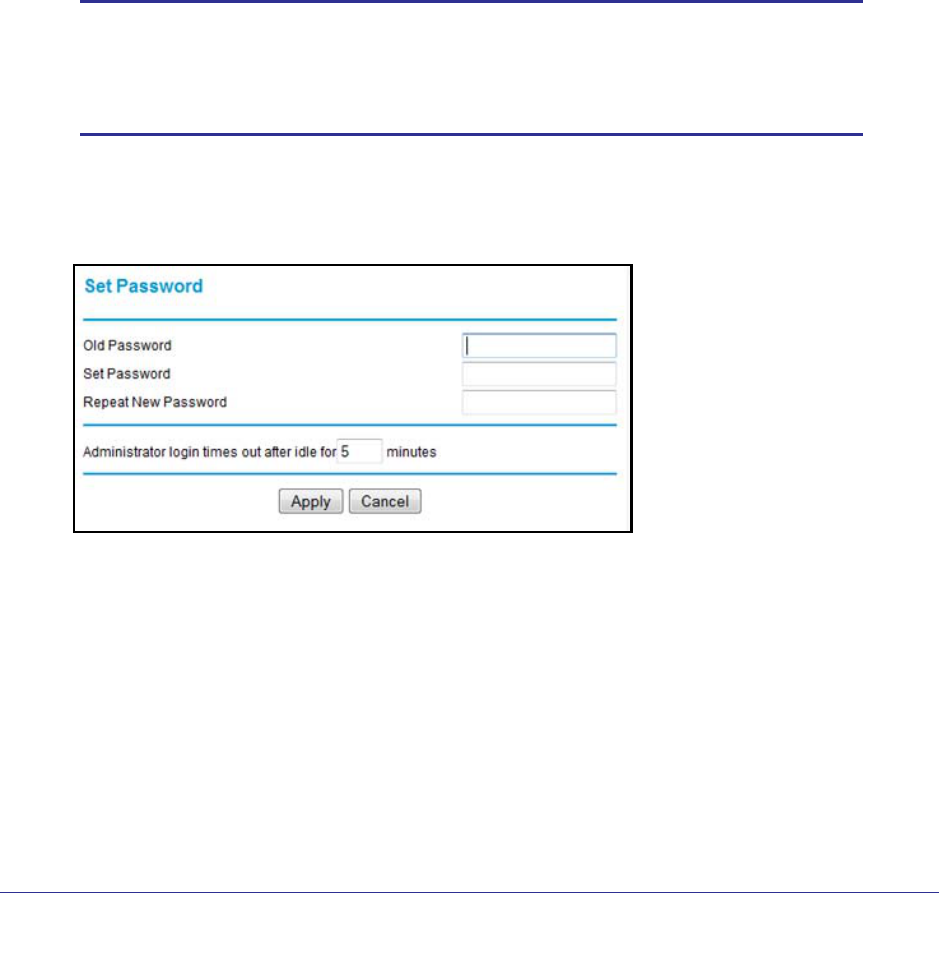
Change Password and Login Time-Out
For security reasons, the modem router has its own user name and password that default to
admin and password. You can and should change these to a secure user name and
password that are easy to remember. The ideal password contains no dictionary words from
any language and is a mixture of upper case and lower case letters, numbers, and symbols.
It can be up to 30 characters.
Note: The modem router user name and password are not the same as
the user name and password for logging in to your Internet
connection. See Types of Logins on page 28 for more information
about login types.
To change the password and login time-out:
1. Select Maintenance > Set Password to display the following screen:.
2. Enter the old password.
3. Enter the new password twice.
4. Change the login time-out to a value between 1 and 99 minutes if the default value of 5
minutes does not meet your needs.
The administrator’s login to the modem router configuration times out after a period of
inactivity to prevent someone else from accessing the modem router interface when you
step away.
5. Click Apply to save your changes.

Modem Router Setup
28
N300 Wireless ADSL2+ Modem Router DGN2200v3
After changing the password, you are required to log in again to continue the
configuration. If you have backed up the modem router settings previously, you should do
a new backup so that the saved settings file includes the new password. See To back up
the modem router configuration file: on page 59 for information about backing up your
network configuration.
Log Out Manually
The modem router interface provides a Logout command at the bottom of the modem router
menus. Log out when you expect to be away from your computer for a relatively long period
of time.
Types of Logins
There are three separate types of logins that have different purposes. It is important that you
understand the difference so that you know which login to use when.
• Modem router login logs you in to the modem router interface. See Log In to the Modem
Router on page 20 for details about this login.
• ISP login logs you in to your Internet service. Your service provider has provided you with
this login information in a letter or some other way. If you cannot find this login
information, contact your service provider.
• Wi-Fi network name and passphrase logs you in to your wireless network. This login is
preconfigured and can be found on the label on the bottom of your unit. See Chapter 3,
Wireless Settings, for more information.

29
3
3. Wireless Settings
Protecting your network
This chapter describes how to use the Wireless Settings screens to view and change (if needed)
your wireless network settings. Security features to prevent objectionable content from reaching
your PCs are covered in Chapter 4, Security Settings.
This chapter contains the following sections:
• Wireless Adapter Compatibility
• Preset Security
• Security Basics
• Add Clients (Computers or Devices) to Your Network
• Wireless Settings Screen
• Wireless Guest Networks
Wireless Adapter Compatibility
A wireless adapter is the wireless radio in your PC or laptop that lets the PC or laptop
connect to a wireless network. Most PCs and laptops come with an adapter already installed,
but if it is outdated or slow, you can purchase a USB adapter to plug into a USB port.
Make sure the wireless adapter in each computer in your wireless network supports the
same security settings as the modem router. See Preset Security on page 30 for information
about the modem router’s preconfigured security settings.
Note: If you connect devices to your modem router using WPS as
described in Wi-Fi Protected Setup (WPS) Method on page 32,
those devices assume the security settings of the modem router.

Wireless Settings
30
N300 Wireless ADSL2+ Modem Router DGN2200v3
Preset Security
The modem router comes with preset security. This means that the Wi-Fi network name
(SSID), passphrase, and security option (encryption protocol) are preset in the factory. You
can find the preset SSID and passphrase on the bottom of the unit.
• Wi-Fi network name (SSID) identifies your network so devices can find it.
• Passphrase controls access to your network. Devices that know the SSID and the
passphrase can find your wireless network and connect.
Note: The preset SSID and passphrase are uniquely generated for every
device to protect and maximize your wireless security.
• Security option is the type of security protocol applied to your wireless network. The
security protocol in force encrypts data transmissions and ensures that only trusted
devices receive authorization to connect to your network. The preset security option is
WPA-PSK/WPA2-PSK mixed mode, described in Wireless Security Options on page 31.
The Wireless Settings screen lets you view and change the preset security settings.
However, NETGEAR recommends that you not change your preset security settings. If
you do decide to change your preset security settings, make a note of the new settings and
store it in a safe place where you can easily find it.
Security Basics
Unlike wired network data, wireless data transmissions extend beyond your walls and can be
received by any device with a compatible wireless adapter (radio). For this reason, it is very
important to maintain the preset security and understand the other security features available
to you. Besides the preset security settings described in the previous section, your modem
router has the security features described here and in Chapter 4, Security Settings.
• Turn off wireless connectivity
• Disable SSID broadcast
• Restrict access by MAC address
• Wireless security options
Turn Off Wireless Connectivity
You can turn off the wireless connectivity of the modem router by pressing the Wireless
On/Off button on its front panel . For example, if you use your laptop to wirelessly connect
to your modem router and you take a business trip, you can turn off the wireless portion of the
modem router while you are traveling. Other members of your household who use computers
connected to the modem router through Ethernet cables can still use the modem router.

Wireless Settings
31
N300 Wireless ADSL2+ Modem Router DGN2200v3
Disable SSID Broadcast
By default, the modem router broadcasts its Wi-Fi network name (SSID) so devices can find
it. If you change this setting to not allow the broadcast, wireless devices will not find your
modem router unless they are configured with the same SSID.
Note: Turning off SSID broadcast nullifies the wireless network discovery
feature of some products such as Windows XP, but the data is still
fully exposed to a determined snoop using specialized test
equipment like wireless sniffers. If you allow the broadcast, be sure
to keep wireless security enabled.
Restrict Access by MAC Address
You can enhance your network security by allowing access to only specific PCs based on
their Media Access Control (MAC) addresses. You can restrict access to only trusted PCs so
that unknown PCs cannot wirelessly connect to the modem router. The Wireless Station
MAC address filtering adds additional security protection to the wireless security option that
you have in force. The Access list determines which wireless hardware devices are allowed
to connect to the modem router by MAC address. See Advanced Wireless Settings on
page 84 for the procedure.
Wireless Security Options
A security option is the type of security protocol applied to your wireless network. The
security protocol encrypts data transmissions and ensures that only trusted devices receive
authorization to connect to your network. There are several types of encryption: Wi-Fi
Protected Access II (WPA2), WPA, and Wired Equivalent Privacy (WEP). WPA2 is the latest
and most secure, and is recommended if your equipment supports it. WPA has several
options including pre-shared key (PSK) encryption and 802.1x encryption for enterprises.
Note that it is also possible to disable wireless security. NETGEAR does not recommend this.
You can view or change the wireless security options in the Wireless Settings screen. See
Wireless Settings Screen on page 33.
Add Clients (Computers or Devices) to Your Network
Choose either the manual or the WPS method to add wireless computers or devices to your
wireless network.

Wireless Settings
32
N300 Wireless ADSL2+ Modem Router DGN2200v3
Manual Method
To join the wireless network:
1. Open the software that manages your wireless connections on the wireless device
(laptop computer, gaming device, iPhone) that you want to connect to your modem
router. This software scans for all wireless networks in your area.
2. Look for your network and select it. If you did not change the name of your network during
the setup process, look for the default Wi-Fi network name (SSID) and select it. The default
Wi-Fi network name (SSID) is located on the product label on the bottom of the modem
router.
3. Enter the modem router passphrase and click Connect. The default modem router
passphrase is located on the product label on the bottom of the modem router.
4. Repeat steps 1–3 to add other wireless devices.
Wi-Fi Protected Setup (WPS) Method
Wi-Fi Protected Setup (WPS) is a standard that lets you easily join a secure wireless network
with WPA or WPA2 wireless security. The modem router automatically sets security for each
computer or device that uses WPS to join the wireless network. To use WPS, make sure that
your wireless devices are Wi-Fi certified and support WPS. NETGEAR products that use
WPS call it Push 'N' Connect.1
Note: If the wireless network name (SSID) changes each time you add a
WPS client, the Keep Existing Wireless Settings check box on the
Advanced Wireless Settings screen has been cleared. See WPS
Settings on page 85 for more information about this setting.
You can use a WPS button or the modem router interface method to add wireless computers
and devices to your wireless network.
To join the wireless network using a WPS button:
1. Press the WPS button on the modem router front panel.
2. Within 2 minutes, press the WPS button on your wireless computer or device, or follow the
WPS instructions that came with the computer. The device is now connected to your modem
router.
3. Repeat steps 1–2 to add other WPS wireless computers or devices.
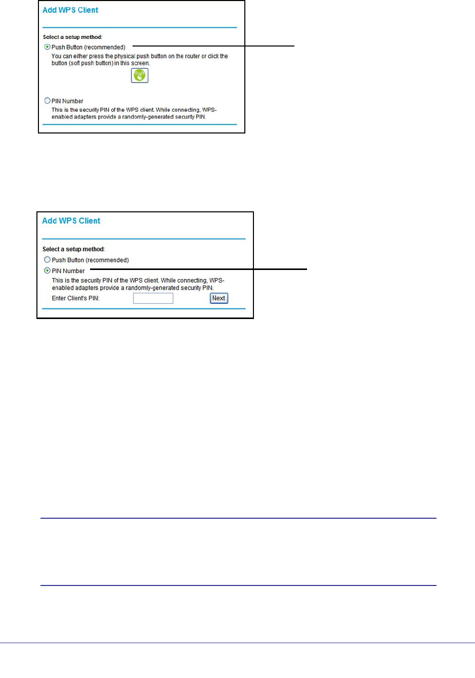
To use the modem router Interface to add a client:
1. Select Add WPS Client at the top of the modem router menus.
1. For a list of other Wi-Fi-certified products available from NETGEAR, go to http://www.wi-fi.org.
Wireless Settings
33
N300 Wireless ADSL2+ Modem Router DGN2200v3
2. Click Next. The following screen lets you select the method for adding the WPS client.
WPS Push button method
3. Select either Push Button or PIN Number. With either method, the modem router tries to
communicate with the computer or wireless device, set the wireless security for wireless
device, and allow it to join the wireless network.
The PIN method displays this screen so you can enter the client security PIN number:
WPS PIN method
While the modem router attempts to connect, the WPS LED on the front of the modem
router blinks green. When the modem router establishes a WPS connection, the LED is
solid green and the modem router WPS screen displays a confirmation message.
4. Repeat to add another WPS client to your network.
Wireless Settings Screen
The Wireless Settings screen lets you view or change the wireless network settings. Note
that your preset modem router has a unique network name and password, located on the
product label. NETGEAR recommends that you use these settings. If you decide to change
them, note the new settings and save them in a secure location.
Note: If you use a wireless computer to change the wireless network
name (SSID) or security options, you are disconnected when you
click Apply. To avoid this problem, use a computer with a wired
connection to access the modem router.
Wireless Settings
34
N300 Wireless ADSL2+ Modem Router DGN2200v3
Consider Every Device on Your Network
Before you begin, check the following:
• Every wireless computer has to be able to obtain an IP address by DHCP from the
modem router as described in Use Standard TCP/IP Properties for DHCP on page 18.
• Each computer or wireless adapter in your network must have the same SSID and
wireless mode (bandwidth/data rate) as the modem router. Check that the wireless
adapter on each computer can support the mode and security option you want to use.
• The security option on each wireless device in the network must match the modem router.
For example, if you select a security option that requires a passphrase, be sure to use
same passphrase for each wireless computer in the network.
View or Change Wireless Settings
Your preset modem router comes set up with a unique wireless network name (SSID) and
network password. This information is printed on the label for your modem router. You view or
change these settings in the Wireless Settings screen. You can also use this screen to set up
guest wireless networks.
To view or change wireless settings:
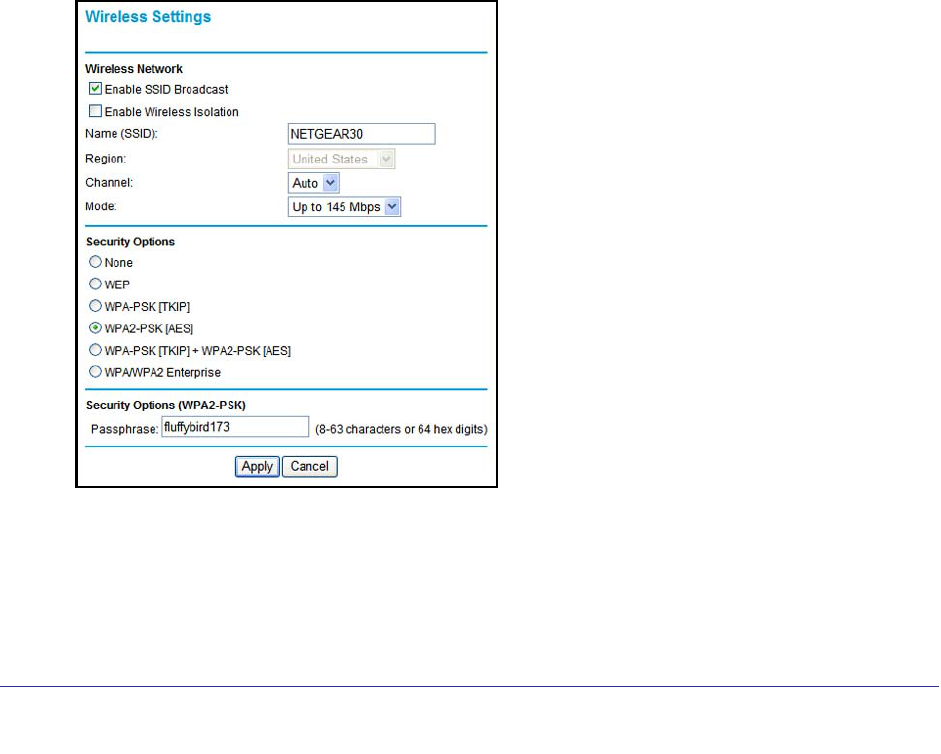
1. Select Setup > Wireless Settings to display the following screen.
2. Make any changes that are needed, and click Apply when done to save your settings.

Wireless Settings
35
N300 Wireless ADSL2+ Modem Router DGN2200v3
Note: The screen sections, settings, and procedures are explained in the
following sections.
3. Set up and test your computers for wireless connectivity:
a. Use your wireless computer or device to join your network. When prompted, enter the
network password.
b. From the wirelessly connected computer, make sure that you can access the
Internet.
Wireless Settings Screen Fields
Wireless Network
The primary network is the one that you usually use. You can set up guest networks too. You
can customize access so that people who use their computers to access your guest network
can use the Internet, but they do not have access to the rest of your home network.
• Enable SSID Broadcast. This setting allows the modem router to broadcast its SSID so
that a wireless station can display this wireless name (SSID) in its scanned network list.
This check box is selected by default. To turn off the SSID broadcast, clear the Enable
SSID Broadcast check box and click Apply.
• Enable Wireless Isolation. When this check box is selected, wireless stations cannot
communicate with each other or with stations on the wired network. By default, this check
box is not selected.
• Name (SSID). The SSID is also known as the wireless network name. Enter a
32-character (maximum) name in this field. This field is case-sensitive. The default SSID
for your primary network is randomly generated, and there is typically no need to change
it. If you want to set up guest networks, NETGEAR does recommend that you customize
the default guest network names (SSIDs).
• Region. The location where the modem router is used. It might not be legal to operate the
modem router in a region other than the regions listed.
• Channel. The wireless channel used by the gateway: 1 through 13. Do not change the
channel unless you experience interference (shown by lost connections or slow data
transfers). If this happens, experiment with different channels to see which is the best.
• Mode. Up to 150 Mbps is the default and allows 802.11n and 802.11g wireless devices to
join the network. g & b supports up to 54 Mbps. Up to 65 Mbps supports up to 65 Mbps.
Security Options Settings
The Security Options section of the Wireless Settings screen lets you change the security
option and passphrase. The primary network for your preset modem router is already set up
with WPA2 and WPA security. NETGEAR recommends that you set up wireless security for
each guest network that you plan to use. For information about changing these settings, see
the following sections.
Wireless Settings
36
N300 Wireless ADSL2+ Modem Router DGN2200v3
To change the WPA Security Option and passphrase:
1. In the Security Options section, select the WPA option that you want.
2. Enter the passphrase that you want to use. It is a text string from 8 to 63 characters.
3. Click Apply.
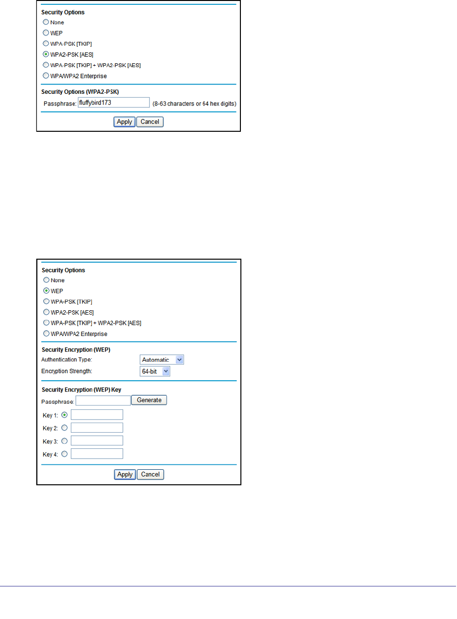
To set up WEP security:
Note that WEP is a legacy security setting that is less effective than WPA or WPA2.
NETGEAR recommends that you use WPA or WPA2 security unless you have an older
computer that is not compatible with WPA or WPA2.
1. In the Security Options section of the Wireless Settings screen, select WEP:
2. Select the authentication type. The default is Automatic. Other choices are Open System
(any client can authenticate itself to the network) and Shared Key (a passphrase and a
four-way challenge are needed for authentication).
3. Select the encryption strength setting, either 64 bit or 128 bit.
Wireless Settings
37
N300 Wireless ADSL2+ Modem Router DGN2200v3
4. Enter the four data encryption keys either manually or automatically. These values must be
identical on all computers and access points in your network.
• Automatic. Enter a word or group of printable characters in the Passphrase field and
click Generate. The four key fields are automatically populated with key values.
• Manual. The number of hexadecimal digits that you enter depends on the encryption
strength setting:
- For 64-bit WEP, enter 10 hexadecimal digits (any combination of 0–9, a–f, or
A–F).
- For 128-bit WEP, enter 26 hexadecimal digits (any combination of 0–9, a–f, or
A–F).
5. Select the radio button for the key you want to make active.
Make sure that you understand how the WEP key settings are configured in your wireless
adapter. Wireless adapter configuration utilities such as the one in Windows XP allow one
key entry, which has to match the default key you set in the modem router.
6. Click Apply.
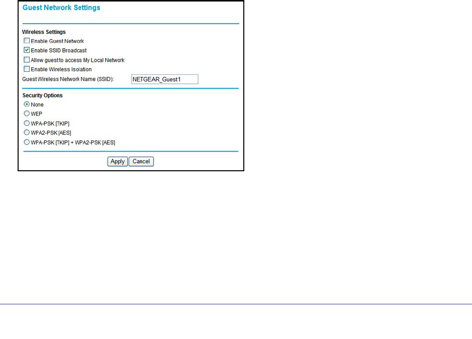
Wireless Guest Networks
A wireless guest network allows you to provide guests access to your wireless network
without prior authorization of each individual guest. You can set up wireless guest networks
and specify the security options for each wireless guest network.
Select Setup > Guest Network to display the following screen:
Enable Guest Network. Select this check box if you want to use a guest network.
Enable SSID Broadcast. This setting allows the modem router to broadcast its SSID so
wireless stations can see this wireless name (SSID) in their scanned network lists. This
check box is selected by default. To turn off the SSID broadcast, clear the Allow Broadcast
of Name (SSID) check box and click Apply.
Wireless Settings
38
N300 Wireless ADSL2+ Modem Router DGN2200v3
Allow guests to access My Local Network. If you want guests to have access to your
home network instead of just Internet access, then select this check box.
Enable Wireless Isolation. If this check box is selected, then wireless clients (computers or
wireless devices) that join the network can use the Internet, but cannot access each other or
access Ethernet devices on the network.
Guest Wireless Network Name (SSID). Change the network name to one that you will
easily recognize.
Security Options. NETGEAR strongly recommends that you set up wireless security for
your guest network. For information about wireless security, see Security Basics on page 30
To set up a wireless guest network:
1. Select Setup > Guest Network.
2. Select the Enable Guest Network check box.
3. You can specify whether the SSID broadcast is enabled, and whether you want to allow the
guest to access your local network. You can also change the SSID.
• NETGEAR strongly recommends that you change the SSID to a different name. Note
that the SSID is case-sensitive. For example, GuestNetwork is not the same as
Guestnetwork.
• For guest networks, wireless security is disabled by default. NETGEAR strongly
recommends that you implement wireless security for the guest network.
4. Select a security option for the guest network and specify the password.
5. When you have finished making changes, click Apply.

39
4
4. Security Settings
Keeping unwanted content out of your network
This chapter explains how to use the basic firewall features of the modem router to prevent
objectionable content from reaching the PCs and other devices connected to your network.
This chapter contains the following sections:
• Logs
• Keyword Blocking of HTTP Traffic
• Firewall Rules to Control Network Access
• Port Triggering to Open Incoming Ports
• Port Forwarding to Permit External Host Communications
• How Port Forwarding Differs from Port Triggering
• Set Up Port Forwarding to Local Servers
• Set Up Port Triggering
• Set the Time Zone
• Schedule Services
• Enable Security Event Email Notification
Security Settings
40
N300 Wireless ADSL2+ Modem Router DGN2200v3
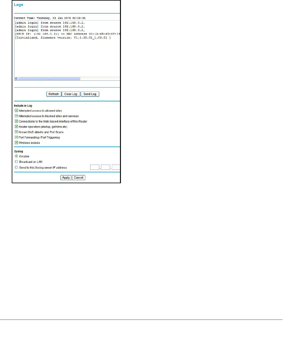
Logs
The modem router logs security-related events such as denied incoming service requests,
hacker probes, and administrator logins. If you enable content filtering in the Block Sites
screen, the Logs screen show you when someone on your network tries to access a blocked
site. If you enable email notification, you will receive these logs in an email message.
To view the log, select Security > Logs. A screen similar to the following displays:
The Include in Log check boxes allow you to select which events are logged. You can write
the logs to a computer running a syslog program. To activate this feature, select Broadcast
on LAN, or enter the IP address of the server where the syslog file will be written. The
security log entries include the following information:
• Date and time.The date and time the log entry was recorded.
• Description or action. The type of event and what action was taken, if any.
• Source IP. The IP address of the initiating device for this log entry.
• Source port and interface. The service port number of the initiating device, and whether
it originated from the LAN or WAN.
• Destination. The name or IP address of the destination device or website.
• Destination port and interface. The service port number of the destination device, and
whether it is on the LAN or WAN.

Security Settings
41
N300 Wireless ADSL2+ Modem Router DGN2200v3
Examples of Log Messages
Following are examples of log messages. In all cases, the log entry shows the time stamp as
day, year-month-date hour:minute:second.
Activation and Administration
Tue, 2006-05-21 18:48:39 - NETGEAR activated
[This entry indicates a power-up or reboot with initial time entry.]
Tue, 2006-05-21 18:55:00 - Administrator login successful-IP:192.168.0.2
Thu, 2006-05-21 18:56:58 - Administrator logout - IP:192.168.0.2
[This entry shows an administrator logging in and out from IP address 192.168.0.2.]
Tue, 2006-05-21 19:00:06 - Login screen timed out - IP:192.168.0.2
[This entry shows a time-out of the administrator login.]
Wed, 2006-05-22 22:00:19 - Log emailed
[This entry shows when the log was emailed.]
Dropped Packets
Wed, 2006-05-22 07:15:15 - TCP packet dropped - Source:64.12.47.28,4787,WAN -
Destination:134.177.0.11,21,LAN - [Inbound Default rule match]
Sun, 2006-05-22 12:50:33 - UDP packet dropped - Source:64.12.47.28,10714,WAN -
Destination:134.177.0.11,6970,LAN - [Inbound Default rule match]
Sun, 2006-05-22 21:02:53 - ICMP packet dropped -
Source:64.12.47.28,0,WAN - Destination:134.177.0.11,0,LAN - [Inbound Default
rule match]
[These entries show an inbound FTP (port 21) packet, a User Datagram Protocol (UDP)
packet (port 6970), and an Internet Control Message Protocol (ICMP) packet (port 0) being
dropped as a result of the default inbound rule, which states that all inbound packets are
denied.]
Security Settings
42
N300 Wireless ADSL2+ Modem Router DGN2200v3
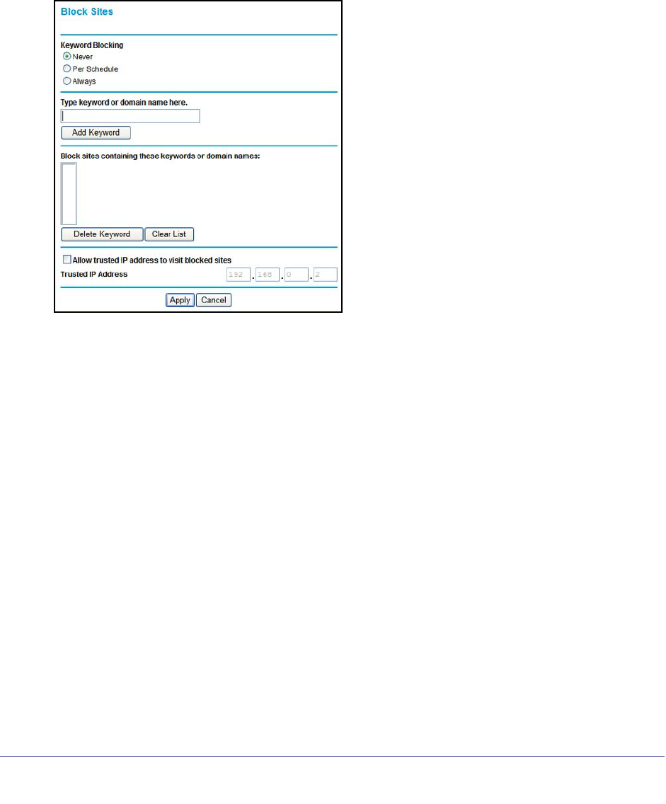
Keyword Blocking of HTTP Traffic
Use keyword blocking to prevent certain types of HTTP traffic from accessing your network.
The blocking can be always or according to a scheduled.
To block sites using keywords:
1. Select Security > Block Sites.
2. Select one of the keyword blocking options:
• Per Schedule. Turn on keyword blocking according to the Schedule screen settings.
• Always. Turn on keyword blocking all the time, independent of the Schedule screen.
3. In the Keyword field, enter a keyword or domain, click Add Keyword, and click Apply.
The Keyword list. supports up to 32 entries. Here are some sample entries:
• Specify XXX to block http://www.badstuff.com/xxx.html.
• Specify .com if you want to allow only sites with domain suffixes such as .edu or .gov.
• Enter a period (.) to block all Internet browsing access.
To delete a keyword or domain:
1. Select the keyword or domain that you want to delete from the list.
2. Click Delete Keyword and click Apply to save your changes.
To specify a trusted computer:
You can exempt one trusted computer from blocking and logging. The computer you exempt
has to have a fixed IP address.
1. In the Trusted IP Address field, enter the IP address.
2. Click Apply to save your changes.
Security Settings
43
N300 Wireless ADSL2+ Modem Router DGN2200v3
Firewall Rules to Control Network Access
Your modem router has a firewall that blocks unauthorized access to your wireless network
and permits authorized inbound and outbound communications. Authorized communications
are established according to inbound and outbound rules. The firewall has the following two
default rules. You can create custom rules to further restrict the outbound communications or
more widely open the inbound communications:
• Inbound. Block all access from outside except responses to requests from the LAN side.
• Outbound. Allow all access from the LAN side to the outside.
Set Up Firewall Rules
The Firewall Rules screen lets you configure custom rules to make exceptions to the default
rules. Exceptions can be based on the service or application, source or destination IP
addresses, and time of day. You can log traffic that matches or does not match the rule and
change the order of rule precedence.
All traffic attempting to pass through the firewall is subjected to the rules in the order shown in
the Rules table from the top (highest precedence) to the default rules at the bottom. In some
cases, the order of precedence is important to determine which communications are allowed
into or out of the network.
To set up firewall rules:
1. Select Security > Firewall Rules to display the following screen:
2. To add an outbound rule, click Add under Outbound Services.
For To edit or delete a rule, select its button on the left side and click Edit or Delete.
3. To change the order of precedence:
a. Select the button on the left side of the rule and click Move.
b. At the prompt, enter the number of the new position and click OK.

Security Settings
44
N300 Wireless ADSL2+ Modem Router DGN2200v3
4. To open or close instant messaging, select one of the following radio buttons:
• Close IM Ports. Disables instant messaging traffic.
• Open IM Ports. Enables instant messaging traffic. IM ports are open by default.
5. Click Apply to save your settings.
Port Triggering to Open Incoming Ports
Some application servers (such as FTP and IRC servers) send replies back to multiple port
numbers. Using the port triggering function of your router, you can tell the router to open
additional incoming ports when a particular outgoing port originates a session.
An example is Internet Relay Chat (IRC). Your computer connects to an IRC server at
destination port 6667. The IRC server not only responds to your originating source port, but
also sends an “identify” message to your computer on port 113. Using port triggering, you can
tell the router, “When you initiate a session with destination port 6667, you have to also allow
incoming traffic on port 113 to reach the originating computer.” Using steps similar to the
preceding example, the following sequence shows the effects of the port triggering rule you
have defined:
1. You open an IRC client program to start a chat session on your computer.
2. Your IRC client composes a request message to an IRC server using a destination port
number of 6667, the standard port number for an IRC server process. Your computer then
sends this request message to your router.
3. Your router creates an entry in its internal session table describing this communication
session between your computer and the IRC server. Your router stores the original
information, performs Network Address Translation (NAT) on the source address and port,
and sends this request message through the Internet to the IRC server.
4. Noting your port triggering rule and having observed the destination port number of 6667,
your router creates an additional session entry to send any incoming port 113 traffic to your
computer.
5. The IRC server sends a return message to your router using the NAT-assigned source port
(for example, port 33333) as the destination port. The IRC server also sends an “identify”
message to your router with destination port 113.
6. Upon receiving the incoming message to destination port 33333, your router checks its
session table to determine whether there is an active session for port number 33333.
Finding an active session, the router restores the original address information replaced by
NAT and sends this reply message to your computer.
7. Upon receiving the incoming message to destination port 113, your router checks its session
table and learns that there is an active session for port 113, associated with your computer.
The router replaces the message’s destination IP address with your computer’s IP address
and forwards the message to your computer.
8. When you finish your chat session, your router eventually senses a period of inactivity in the
communications. The router then removes the session information from its session table,
and incoming traffic is no longer accepted on port numbers 33333 or 113.

Security Settings
45
N300 Wireless ADSL2+ Modem Router DGN2200v3
To configure port triggering, you need to know which inbound ports the application needs.
Also, you need to know the number of the outbound port that will trigger the opening of the
inbound ports. You can usually determine this information by contacting the publisher of the
application or the relevant user groups or news groups.
Note: Only one computer at a time can use the triggered application.
Port Forwarding to Permit External Host Communications
In both of the preceding examples, your computer initiates an application session with a
server computer on the Internet. However, you might need to allow a client computer on the
Internet to initiate a connection to a server computer on your network. Normally, your router
ignores any inbound traffic that is not a response to your own outbound traffic. You can
configure exceptions to this default rule by using the port forwarding feature.
A typical application of port forwarding can be shown by reversing the client-server
relationship from the previous web server example. In this case, a remote computer’s
browser needs to access a web server running on a computer in your local network. Using
port forwarding, you can tell the router, “When you receive incoming traffic on port 80 (the
standard port number for a web server process), forward it to the local computer at
192.168.1.123.” The following sequence shows the effects of the port forwarding rule you
have defined:
1. The user of a remote computer opens a browser and requests a web page from
www.example.com, which resolves to the public IP address of your router. The remote
computer composes a web page request message with the following destination
information:
Destination address. The IP address of www.example.com, which is the address of your
router.
Destination port number. 80, which is the standard port number for a web server
process.
The remote computer then sends this request message through the Internet to your
router.
2. Your router receives the request message and looks in its rules table for any rules covering
the disposition of incoming port 80 traffic. Your port forwarding rule specifies that incoming
port 80 traffic should be forwarded to local IP address 192.168.1.123. Therefore, your router
modifies the destination information in the request message:
The destination address is replaced with 192.168.1.123.
Your router then sends this request message to your local network.
3. Your web server at 192.168.1.123 receives the request and composes a return message
with the requested web page data. Your web server then sends this reply message to your
router.

Security Settings
46
N300 Wireless ADSL2+ Modem Router DGN2200v3
4. Your router performs Network Address Translation (NAT) on the source IP address, and
sends this request message through the Internet to the remote computer, which displays the
web page from www.example.com.
To configure port forwarding, you need to know which inbound ports the application needs.
You usually can determine this information by contacting the publisher of the application or
the relevant user groups or news groups.
How Port Forwarding Differs from Port Triggering
The following points summarize the differences between port forwarding and port triggering:
• Port triggering can be used by any computer on your network, although only one
computer can use it at a time.
• Port forwarding is configured for a single computer on your network.
• With port triggering, the router does not need to know the computer’s IP address in
advance. The IP address is captured automatically.
• Port forwarding requires that you specify the computer’s IP address during configuration,
and the IP address can never change.
• Port triggering requires specific outbound traffic to open the inbound ports, and the
triggered ports are closed after a period of no activity.
• Port forwarding is always active and does not need to be triggered.
Set Up Port Forwarding to Local Servers
Using the port forwarding feature, you can allow certain types of incoming traffic to reach
servers on your local network. For example, you might want to make a local web server, FTP
server, or game server visible and available to the Internet.
Use the Port Forwarding/Port Triggering screen to configure the router to forward specific
incoming protocols to computers on your local network. In addition to servers for specific
applications, you can also specify a default DMZ server to which all other incoming protocols
are forwarded.
Before starting, you need to determine which type of service, application, or game you want
to provide, and the local IP address of the computer that will provide the service. The server
computer has to always have the same IP address.
Tip: To ensure that your server computer always has the same IP address,
use the reserved IP address feature of your product.
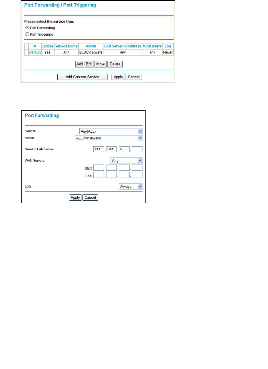
Security Settings
47
N300 Wireless ADSL2+ Modem Router DGN2200v3
To forward specific incoming protocols:
1. Select Advanced > Port Forwarding/Port Triggering to display the following screen:
2. Leave the Port Forwarding radio button selected as the service type.
3. Click Add, and the following screen displays:
4. From the Service list, select the service or game that you will host on your network. If the
service does not appear in the list, see Add a Custom Service on page 47.
5. In the Send to LAN Server field, enter the last digit of the IP address of your local computer
that will provide this service.
6. Click Apply. The service appears in the list on the Port Forwarding screen.
Add a Custom Service
To define a service, game, or application that does not appear in the Service Name list, you
have to first determine which port number or range of numbers is used by the application.
You can usually determine this information by contacting the publisher of the application or
user groups or news groups. When you have the port number information, follow these steps.
To add a custom service:
1. Select Advanced > Port Forwarding/Port Triggering.
2. Select the Port Forwarding radio button as the service type.
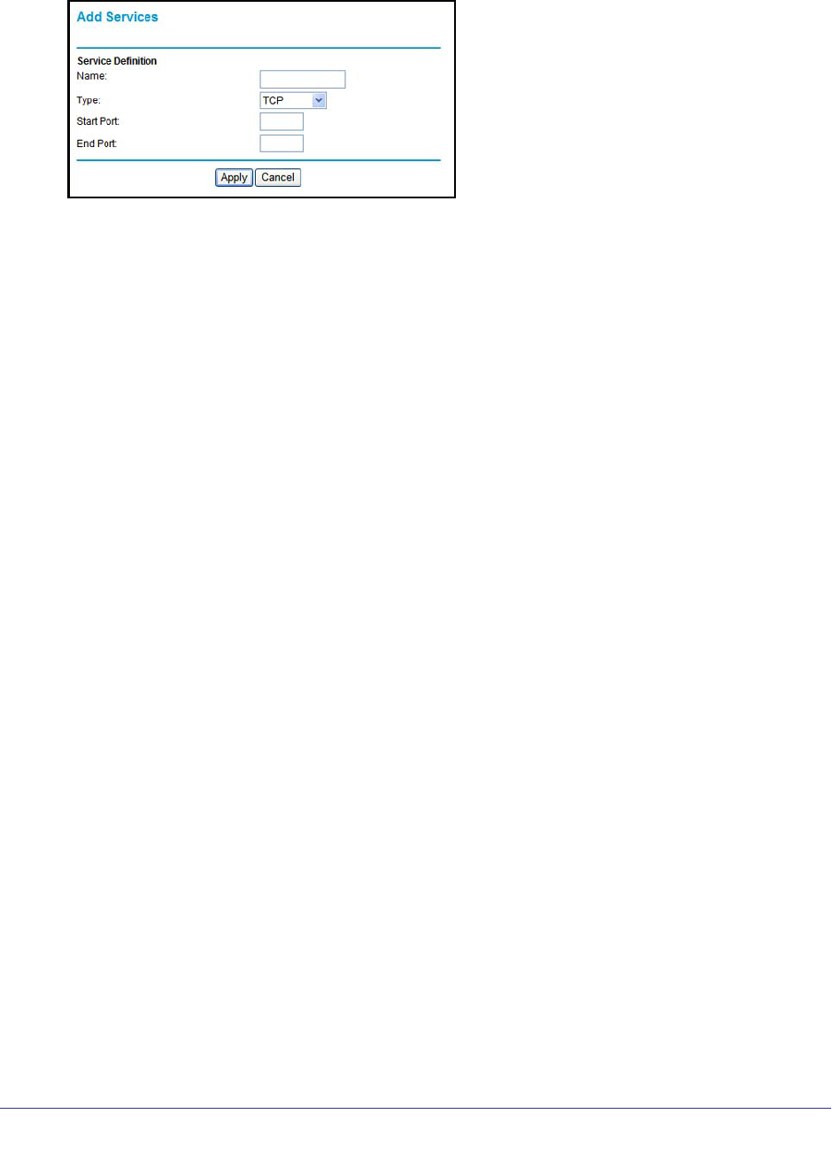
Security Settings
48
N300 Wireless ADSL2+ Modem Router DGN2200v3
3. Click the Add Custom Service button to display the following screen:
4. In the Service Name field, enter a descriptive name.
5. In the Protocol field, select the protocol. If you are unsure, select TCP/UDP.
6. In the Starting Port field, enter the beginning port number.
• If the application uses a single port, enter the same port number in the Ending Port
field.
• If the application uses a range of ports, enter the ending port number of the range in
the Ending Port field.
7. In the Server IP Address field, enter the IP address of your local computer that will provide
this service.
8. Click Apply. The service appears in the list in the Port Forwarding/Port Triggering screen.
Edit or Delete a Port Forwarding Entry
To edit or delete a port forwarding entry:
1. In the table, select the radio button next to the service name.
2. Click Edit Service or Delete Service.
Application Example: Make a Local Web Server Public
If you host a web server on your local network, you can use port forwarding to allow web
requests from anyone on the Internet to reach your web server.
To make a local web server public:
1. Assign your web server either a fixed IP address or a dynamic IP address using DHCP
address reservation. In this example, your router will always give your web server an IP
address of 192.168.1.33.
2. In the Port Forwarding/Port Triggering screen, configure the router to forward the HTTP
service to the local address of your web server at 192.168.1.33. HTTP (port 80) is the
standard protocol for web servers.
3. (Optional) Register a host name with a Dynamic DNS service, and configure your router to
use the name. To access your web server from the Internet, a remote user has to know the
IP address that has been assigned by your ISP. However, if you use a Dynamic DNS
service, the remote user can reach your server by a user-friendly Internet name, such as
mynetgear.dyndns.org.

Security Settings
49
N300 Wireless ADSL2+ Modem Router DGN2200v3
Set Up Port Triggering
Port triggering is a dynamic extension of port forwarding that is useful in these cases:
• More than one local computer needs port forwarding for the same application (but not
simultaneously).
• An application needs to open incoming ports that are different from the outgoing port.
When port triggering is enabled, the router monitors outbound traffic looking for a specified
outbound “trigger” port. When the router detects outbound traffic on that port, it remembers
the IP address of the local computer that sent the data. The router then temporarily opens the
specified incoming port or ports, and forwards incoming traffic on the triggered ports to the
triggering computer.
While port forwarding creates a static mapping of a port number or range to a single local
computer, port triggering can dynamically open ports to any computer that needs them and
can close the ports when they are no longer needed.
Note: If you use applications such as multiplayer gaming, peer-to-peer
connections, real-time communications such as instant messaging,
or remote assistance (a feature in Windows XP), you should also
enable Universal Plug and Play (UPnP).
To configure port triggering, you need to know which inbound ports the application needs.
Also, you need to know the number of the outbound port that will trigger the opening of the
inbound ports. You can usually determine this information by contacting the publisher of the
application or user groups or news groups.
To enable port triggering:
1. Select Advanced > Port Forwarding/Port Triggering to display the Port
Forwarding/Port Triggering screen.
Security Settings
50
N300 Wireless ADSL2+ Modem Router DGN2200v3
2. Select the Port Triggering radio button to display the port triggering information.
3. Clear the Disable Port Triggering check box.
Note: If the Disable Port Triggering check box is selected after you
configure port triggering, port triggering is disabled. However, any
port triggering configuration information you added to the router is
retained even though it is not used.
4. In the Port Triggering Timeout field, enter a value up to 9999 minutes. This value controls the
inactivity timer for the designated inbound ports. The inbound ports close when the inactivity
time expires. This is required because the router cannot be sure when the application has
terminated.
To add a port triggering service:
Make sure that you enable port triggering so that the service that you add will be used.
Security Settings
51
N300 Wireless ADSL2+ Modem Router DGN2200v3
1. On the Port Triggering screen, click Add Service. The following screen displays:
2. In the Service Name field, type a descriptive service name.
3. In the Service User list, select Any (the default) to allow this service to be used by any
computer on the Internet. Otherwise, select Single address, and enter the IP address of
one computer to restrict the service to a particular computer.
4. Select the service type, either TCP or UDP or both (TCP/UDP). If you are not sure, select
TCP/UDP.
5. In the Triggering Port field, enter the number of the outbound traffic port that will cause the
inbound ports to be opened.
6. Enter the inbound connection port information in the Connection Type, Starting Port, and
Ending Port fields.
7. Click Apply. The service appears in the Port Triggering Portmap table.
Security Settings
52
N300 Wireless ADSL2+ Modem Router DGN2200v3
Set the Time Zone
The modem router uses the Network Time Protocol (NTP) to obtain the current time and date
from one of several network time servers on the Internet.
To set the time zone:
1. Select Security > Schedule.
2. Select your time zone. This setting determines the blocking schedule and time-stamping of
log entries.
3. If your time zone is in daylight savings time, select the Adjust for daylight savings time
check box to add one hour to standard time.
Note: If your region uses daylight savings time, select Adjust for daylight
savings time on the first day and clear it after the last day.
4. Click Apply to save your settings.

Security Settings
53
N300 Wireless ADSL2+ Modem Router DGN2200v3
Schedule Services
If you enabled service blocking in the Block Services screen or port forwarding in the Ports
screen, you can set up a schedule for when blocking occurs or when access is not restricted.
To schedule services:
1. Select Security > Schedule.
2. To block Internet services based on a schedule, select Every Day or select one or more
days.
3. If you want to limit access completely for the selected days, select All Day. Otherwise, to
limit access during certain times for the selected days, enter times in the Start Blocking and
End Blocking fields.
Note: Enter the values in 24-hour time format. For example, 10:30 a.m. would
be 10 hours and 30 minutes, and 10:30 p.m. would be 22 hours and 30
minutes. If you set the start time after the end time, the schedule is effective
through midnight the next day.
4. Click Apply to save your settings.
Security Settings
54
N300 Wireless ADSL2+ Modem Router DGN2200v3
Enable Security Event Email Notification
To receive logs and alerts by email, provide your email information in the E-mail screen and
specify which alerts you want to receive and how often.
Select Security > Email to display the following screen:
• Turn E-mail Notification On. Select this check box if you want to receive email logs and
alerts from the modem router.
• Send to This E-mail Address. Enter the email address where you want logs and alerts
sent. This email address is also used as the From address. If you leave this field blank,
log and alert messages are not sent by email.
• Your Outgoing Mail Server. Enter the name or IP address of your ISP’s outgoing
(SMTP) mail server (such as mail.myISP.com). You might be able to find this information
in the configuration settings of your email program. Enter the email address to which logs
and alerts are sent. This email address is also used as the From address. If you leave this
field blank, log and alert messages are not sent by email.
• My mail server requires authentication. If you use an outgoing mail server provided by
your current ISP, you do not need to select this field. If you use an email account that is
not provided by your ISP, select this field, and enter the required user name and
password information.
• Send Alerts Immediately. Select the corresponding check box if you would like
immediate notification of a significant security event, such as a known attack, port scan,
or attempted access to a blocked site.
• Send logs according to this schedule. Specifies how often to send the logs: Hourly,
Daily, Weekly, or When Full.
-Days specifies which day of the week to send the log. This is relevant when the log is
sent weekly.

Security Settings
55
N300 Wireless ADSL2+ Modem Router DGN2200v3
-Time specifies the time of day to send the log. This is relevant when the log is sent
daily or weekly.
Note: If the Weekly, Daily, or Hourly option is selected and the log fills up
before the specified period, the log is automatically emailed to the
specified email address. After the log is sent, it is cleared from the
modem router’s memory. If the modem router cannot email the log
file, the log buffer might fill up. In this case, the modem router
overwrites the log and discards its contents.

56
5
5. Network Maintenance
Administering your network
This chapter describes the modem router settings for administering and maintaining the modem
router and home network.
This chapter contains the following sections:
• Upgrade the Modem Router Firmware
• Manually Check for Firmware Upgrades
• Back Up and Manage the Configuration File
• View Router Status
• View Attached Devices
• Run Diagnostic Utilities
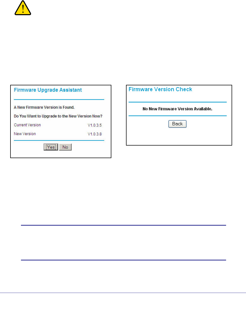
Network Maintenance
57
N300 Wireless ADSL2+ Modem Router DGN2200v3
Upgrade the Modem Router Firmware
The modem router firmware (routing software) is stored in flash memory. By default, when
you log in to your modem router, it checks the NETGEAR website for new firmware and alerts
you if there is a newer version.
WARNING!
When uploading firmware to the modem router, do not interrupt
the Web browser by closing the window, clicking a link, or loading
a new page. If the browser is interrupted, it could corrupt the
firmware.
Automatic Firmware Check
When automatic firmware checking is on, the modem router performs the check and notifies
you if an upgrade is available or not as shown here.
To upgrade the firmware:
1. Click Yes to allow the modem router to download and install the new firmware. The
upgrade process could take a few minutes. When the upload is complete, your modem
router restarts.
2. Go to the DGN2200v3 support page at http://www.netgear.com/support.and read the new
firmware release notes to determine whether you need to reconfigure the modem router
after upgrading.
Note: If you get a “Firmware needs to be reloaded” message, it means a
problem has been detected with the modem router’s firmware.
Follow the prompts to correct the problem or see Incorrect Date or
Time on page 107 for a description of the steps.
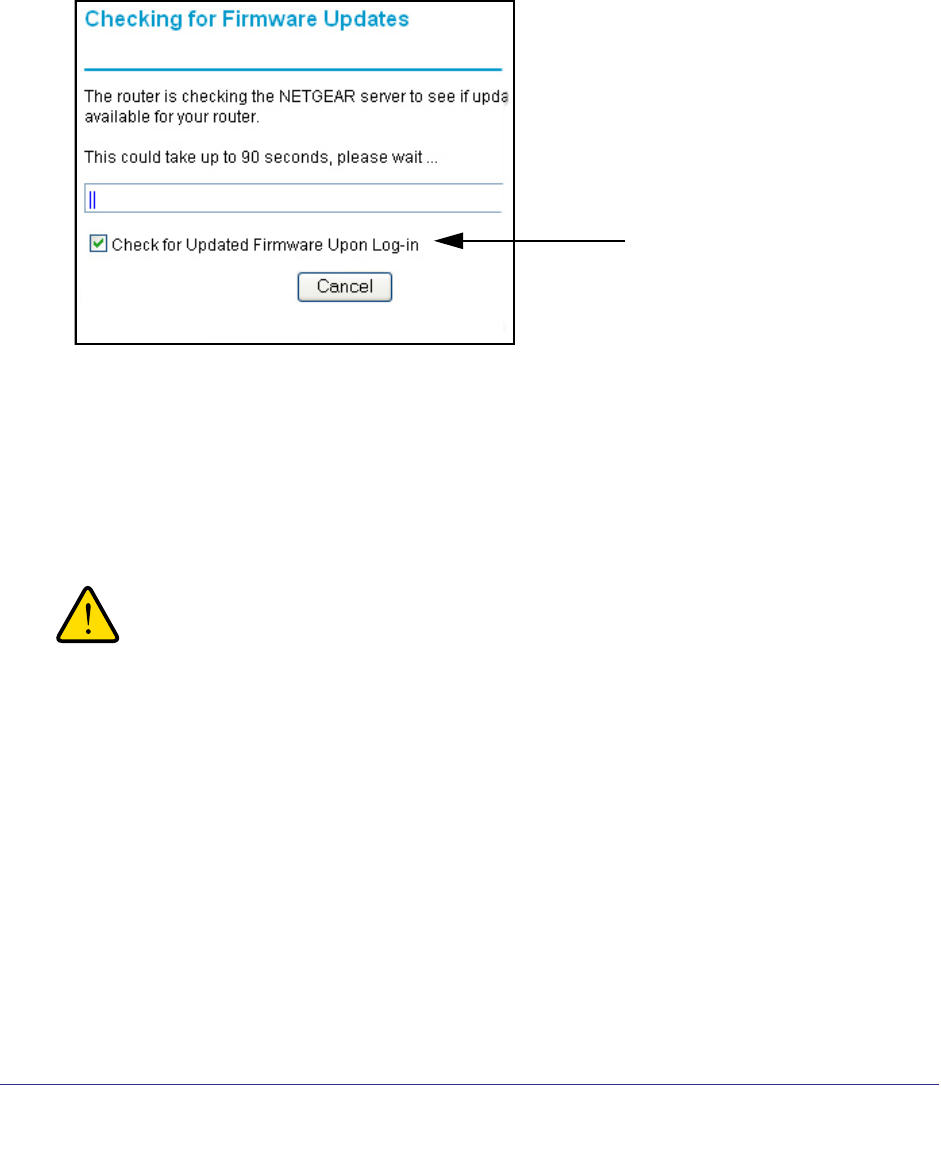
Network Maintenance
58
N300 Wireless ADSL2+ Modem Router DGN2200v3
To stop automatic firmware checking:
You can turn the automatic firmware checking off and check for firmware updates manually if
you prefer. See Manually Check for Firmware Upgrades on page 58. To turn off the automatic
firmware check at login:
1. Select Maintenance > Router Upgrade.
2. Clear the Check for Updated Firmware Upon Log-in check box.
Manually Check for Firmware Upgrades
You can use the Router Upgrade screen to manually check the NETGEAR website for newer
versions of firmware for your product.
To manually check for firmware, and upgrade the modem router:
WARNING!
When uploading firmware to the modem router, do not interrupt
the Web browser by closing the window, clicking a link, or loading
a new page. If the browser is interrupted, it could corrupt the
firmware.
1. Select Maintenance > Router Status and make a note of the modem router firmware
version number.
2. Go to the DGN2200v3 support page on the NETGEAR website at
http://www.netgear.com/support.
3. If the firmware version on the NETGEAR website is newer than the firmware on your
modem router, download the file to your computer.
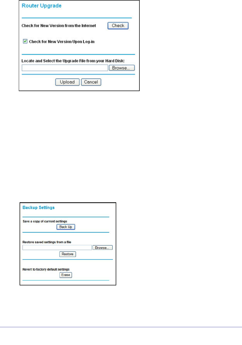
Network Maintenance
59
N300 Wireless ADSL2+ Modem Router DGN2200v3
4. Select Maintenance > Router Upgrade to display the following screen:
5. Click Browse, and locate the firmware you downloaded (the file ends in .img).
6. Click Upload to send the firmware to the modem router.
When the upload is complete, your modem router restarts. The upgrade process typically
takes about 1 minute. Read the new firmware release notes to determine whether or not
you need to reconfigure the modem router after upgrading.
Back Up and Manage the Configuration File
The modem router configuration settings are stored in a configuration file (*.cfg). This file can
be backed up to your computer, restored, or used to revert to factory default settings.
To back up the modem router configuration file:
1. Select Maintenance > Backup Settings to display the following screen:
2. Click Save to save a copy of the current settings.
3. Choose a location to store the .cfg file that is on a computer on your network.
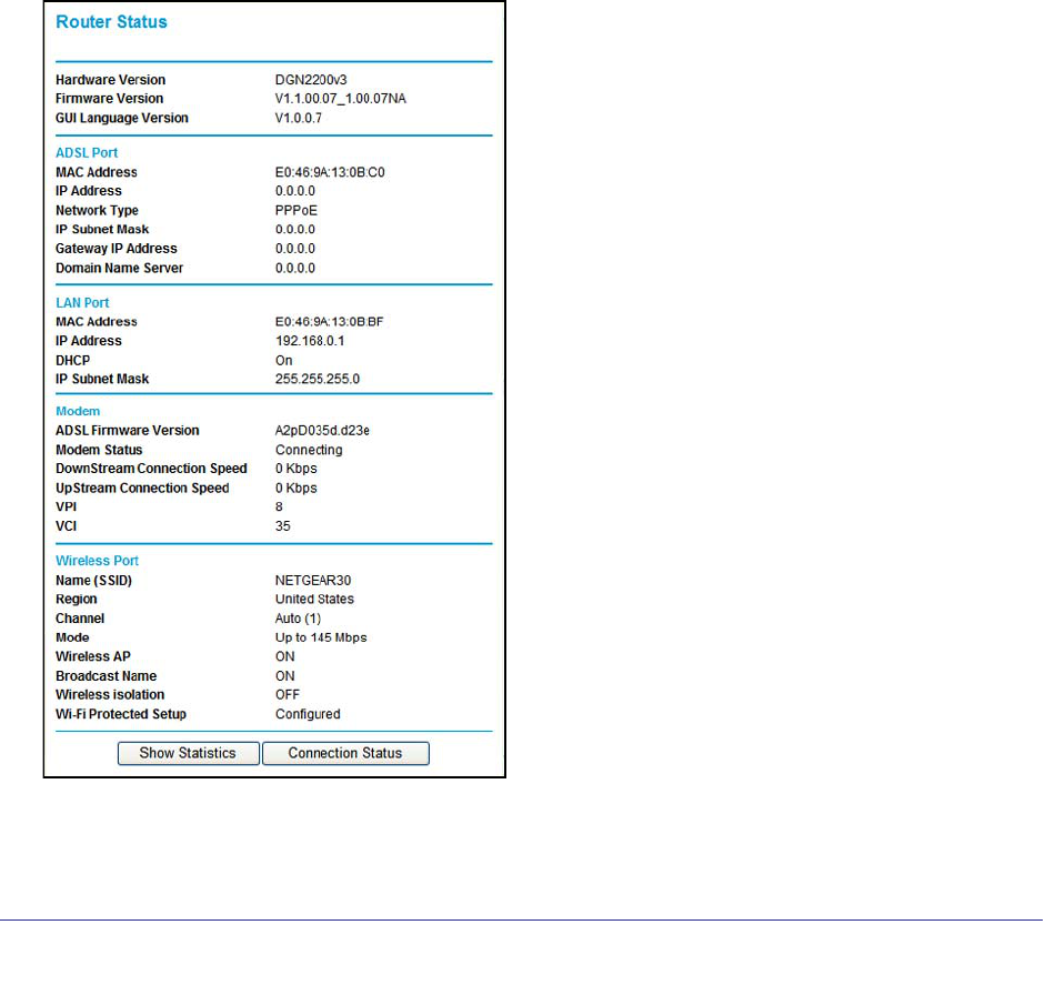
Network Maintenance
60
N300 Wireless ADSL2+ Modem Router DGN2200v3
To restore the configuration file:
1. Enter the full path to the file on your network, or click the Browse button to find the file.
2. When you have located the .cfg file, click the Restore button to upload the file to the modem
router.
Upon completion, the modem router reboots.
To erase the configuration:
Click the Erase button to reset the modem router to its factory default settings. Erase sets the
password to password, the LAN IP address to 192.168.0.1, and enables the modem router’s
DHCP.
View Router Status
Select Maintenance > Router Status to display this screen. The Router Status screen
provides status and usage information.
Hardware and Firmware Version. The model of the hardware and the currently running
firmware version.