Netgear orporated 12400216 D6200 WiFi Modem Router User Manual D6200 WiFi Modem Router
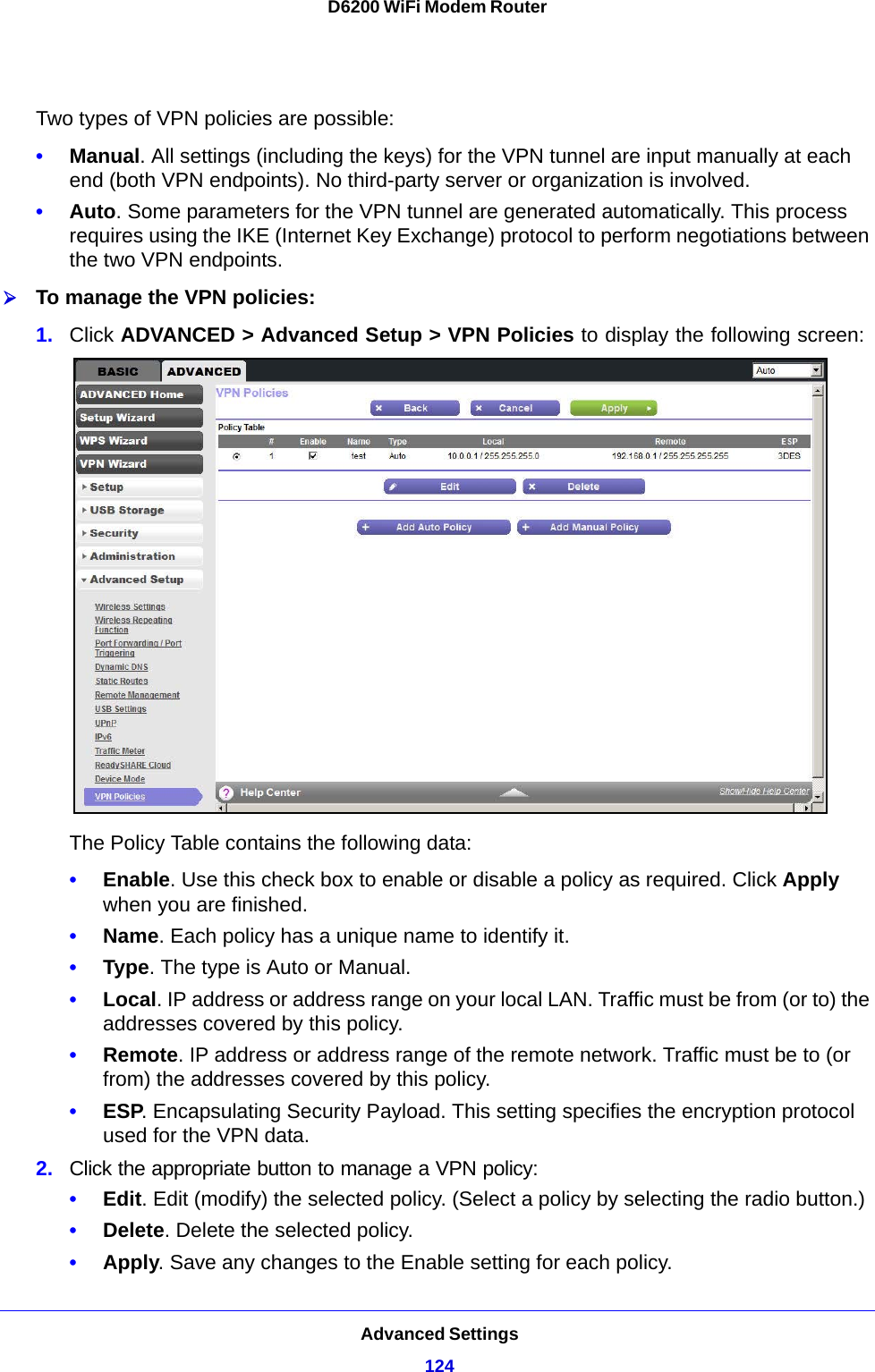
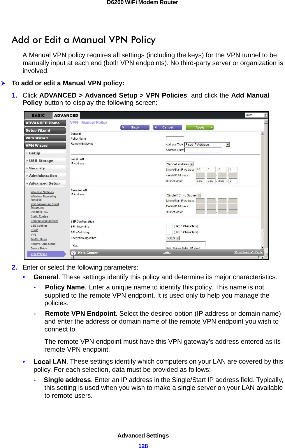
Netgear Incorporated D6200 WiFi Modem Router D6200 WiFi Modem Router
Contents
- 1. Users manual I
- 2. Users manual II
- 3. User manual I
- 4. User manual II
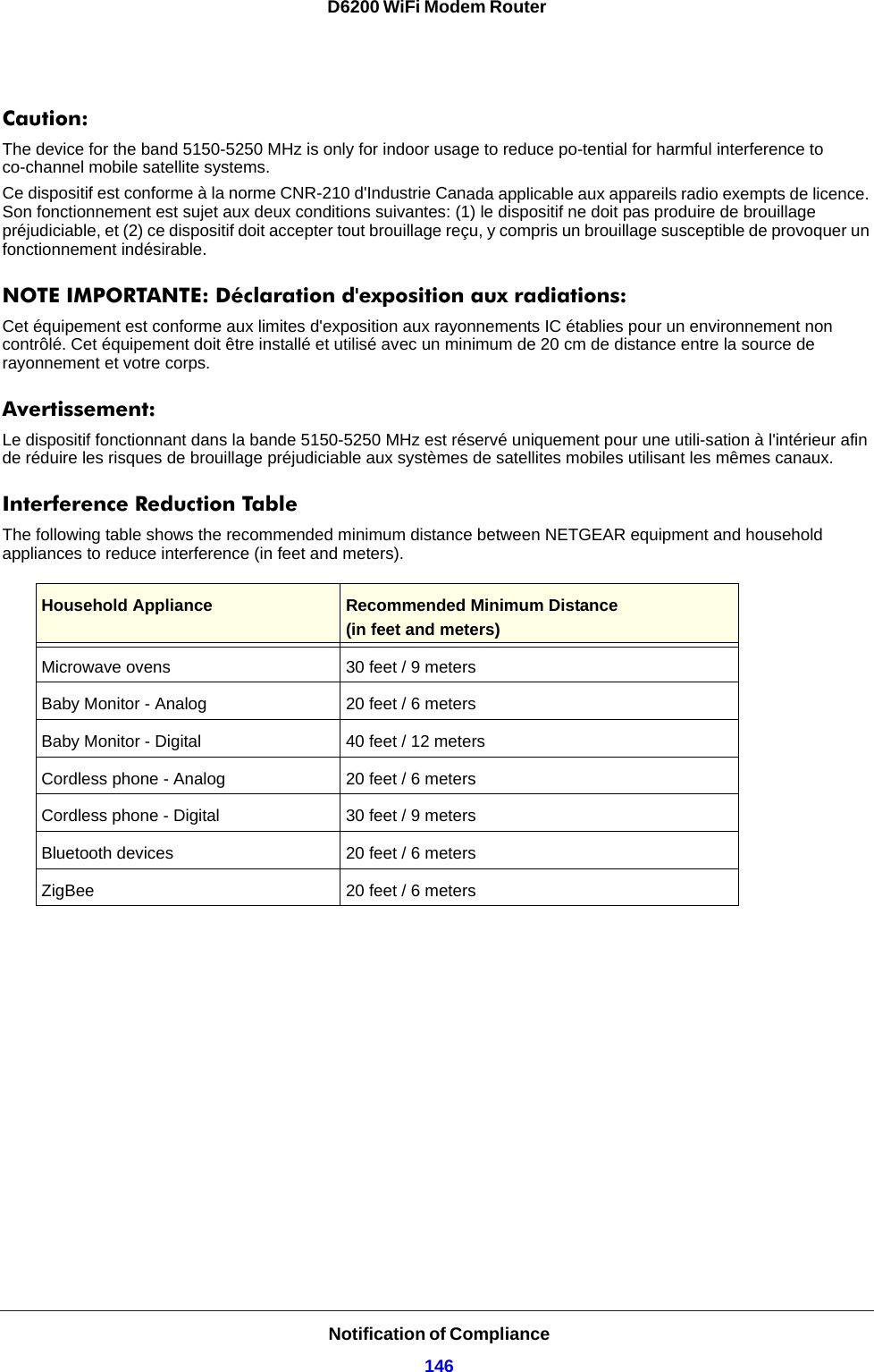
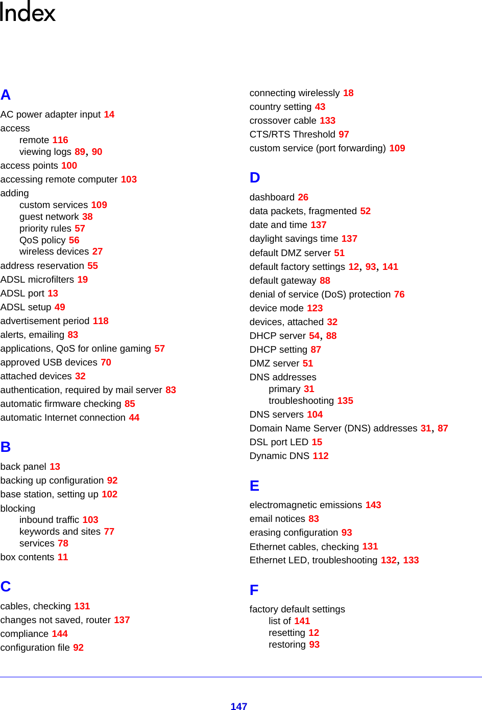
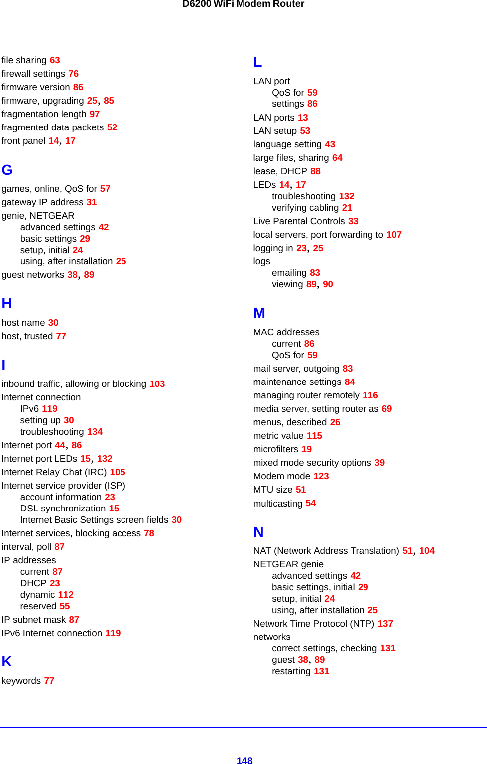
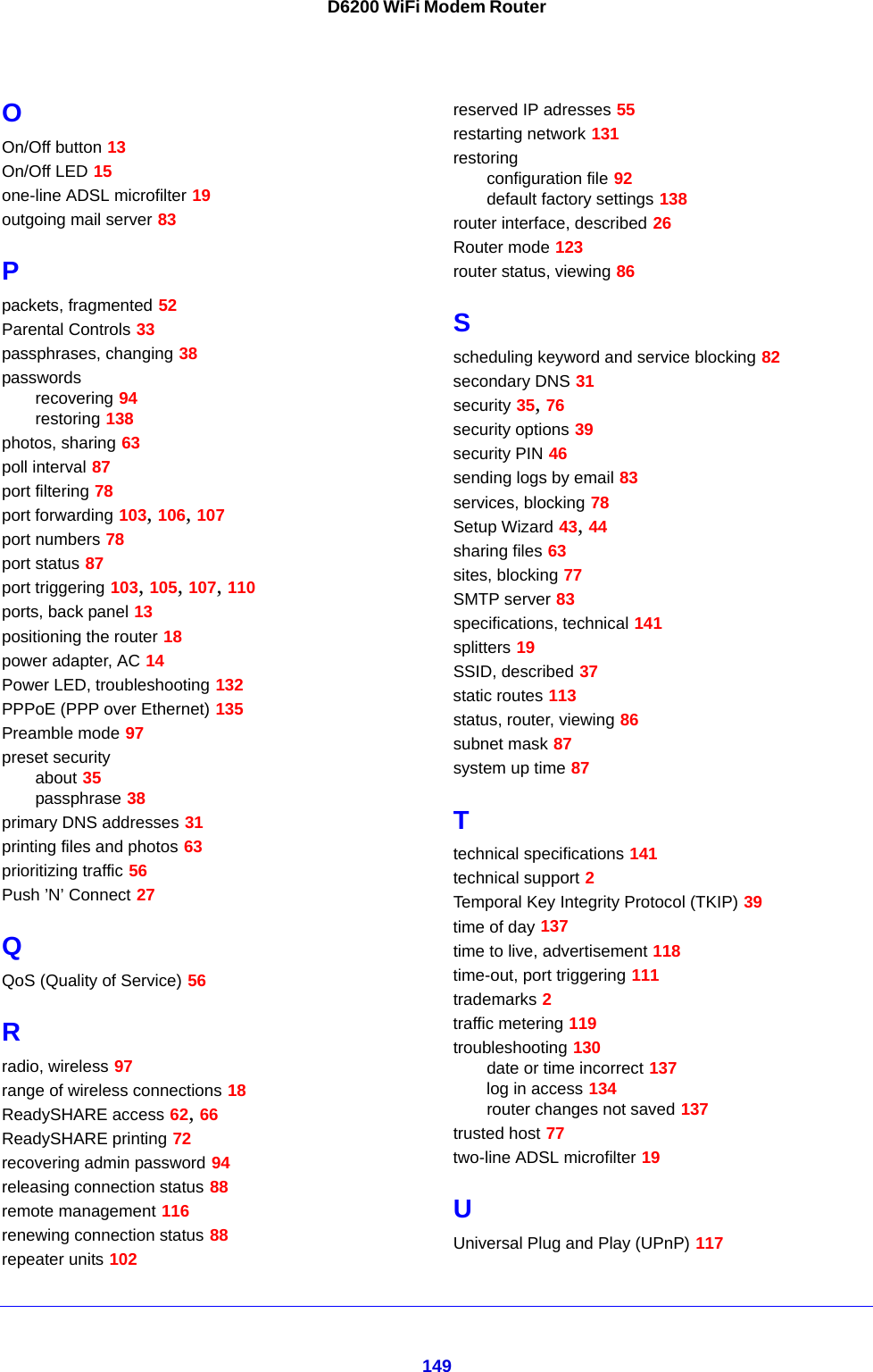
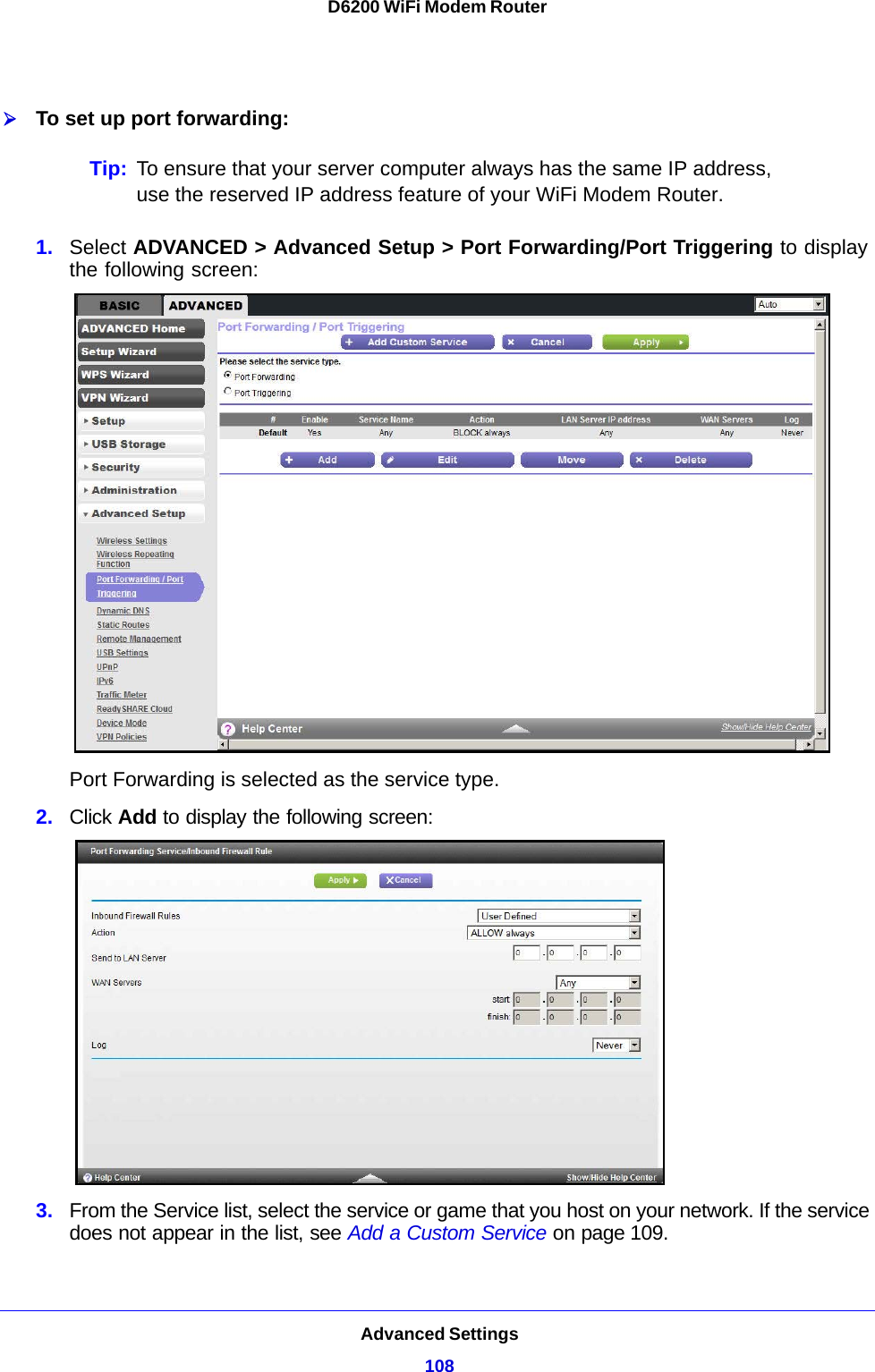
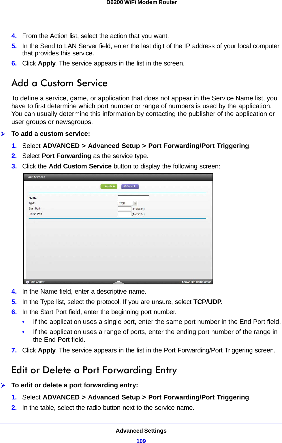
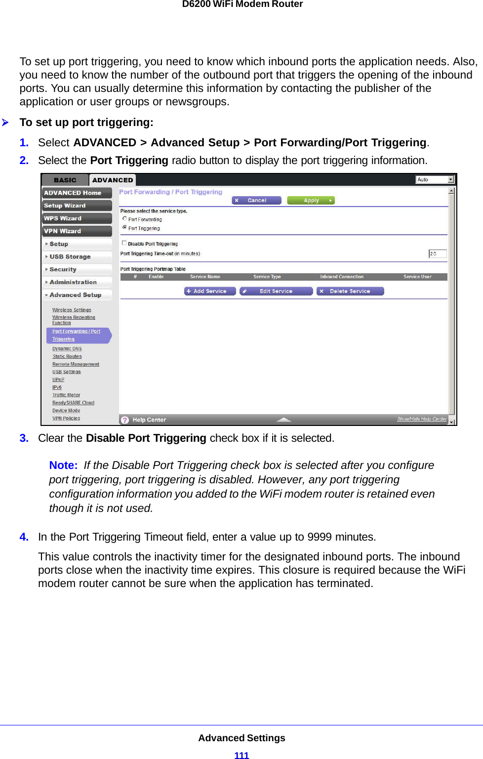
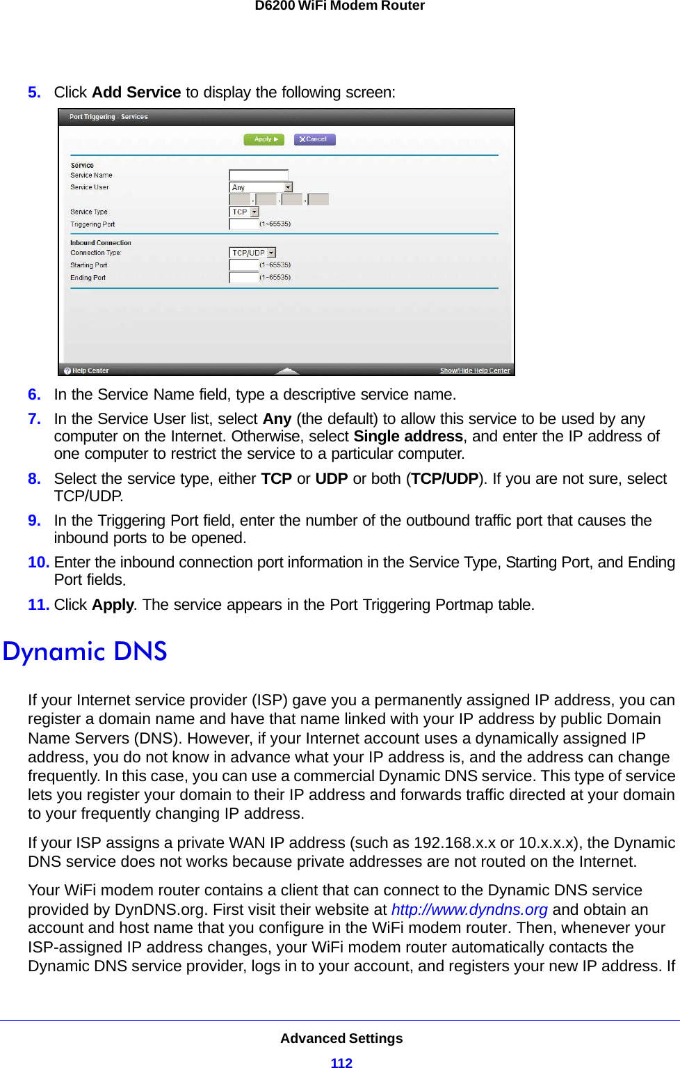
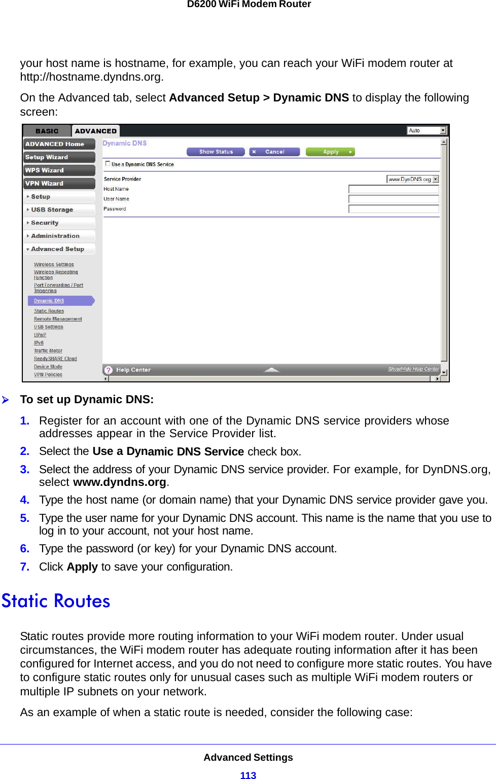
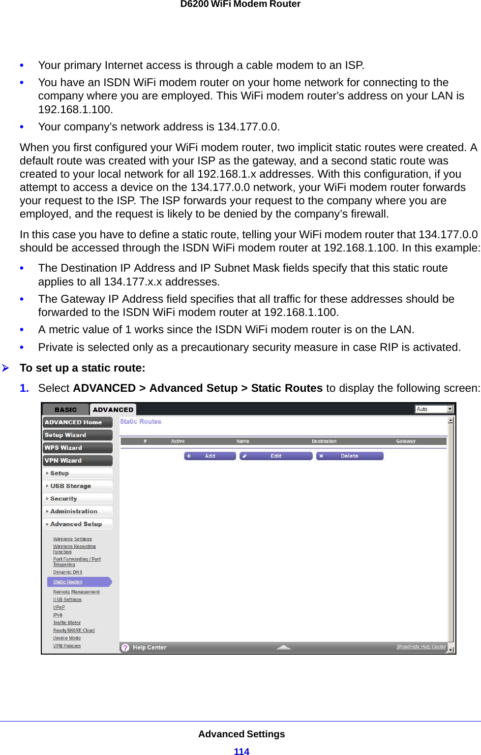
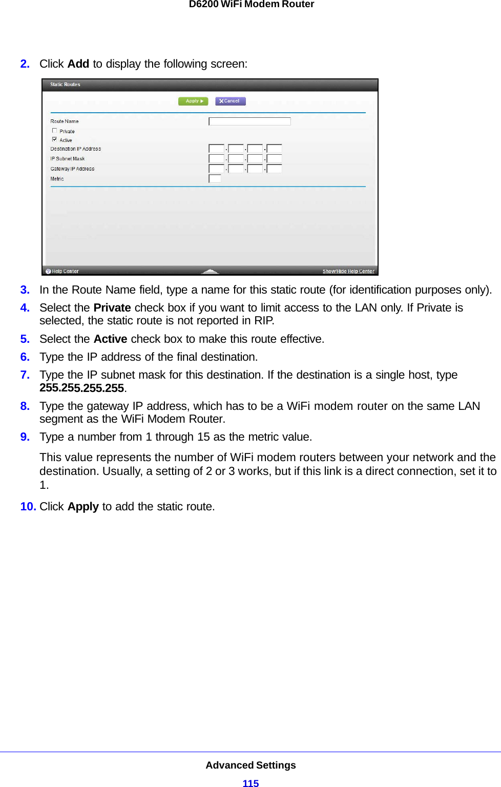
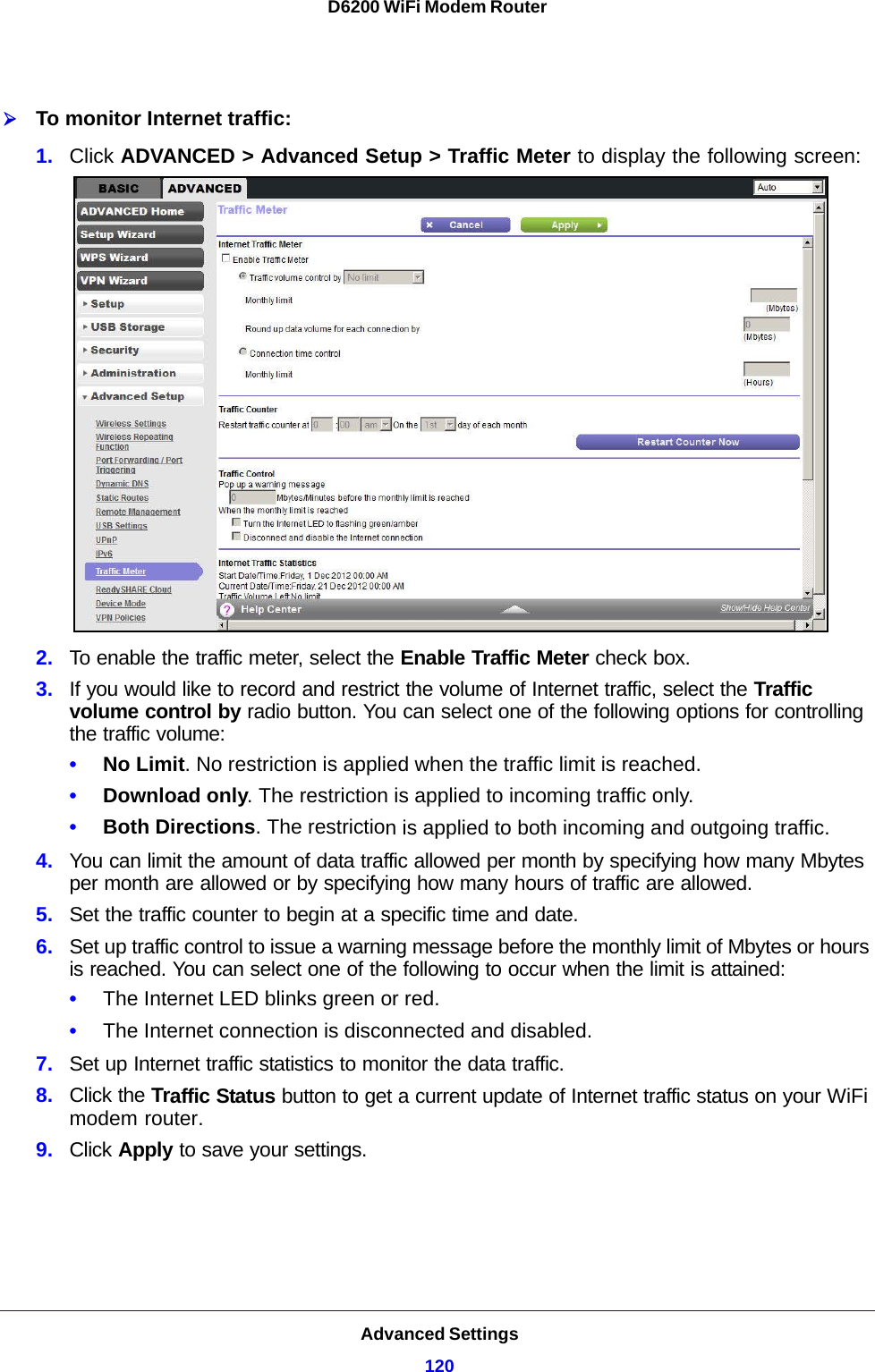
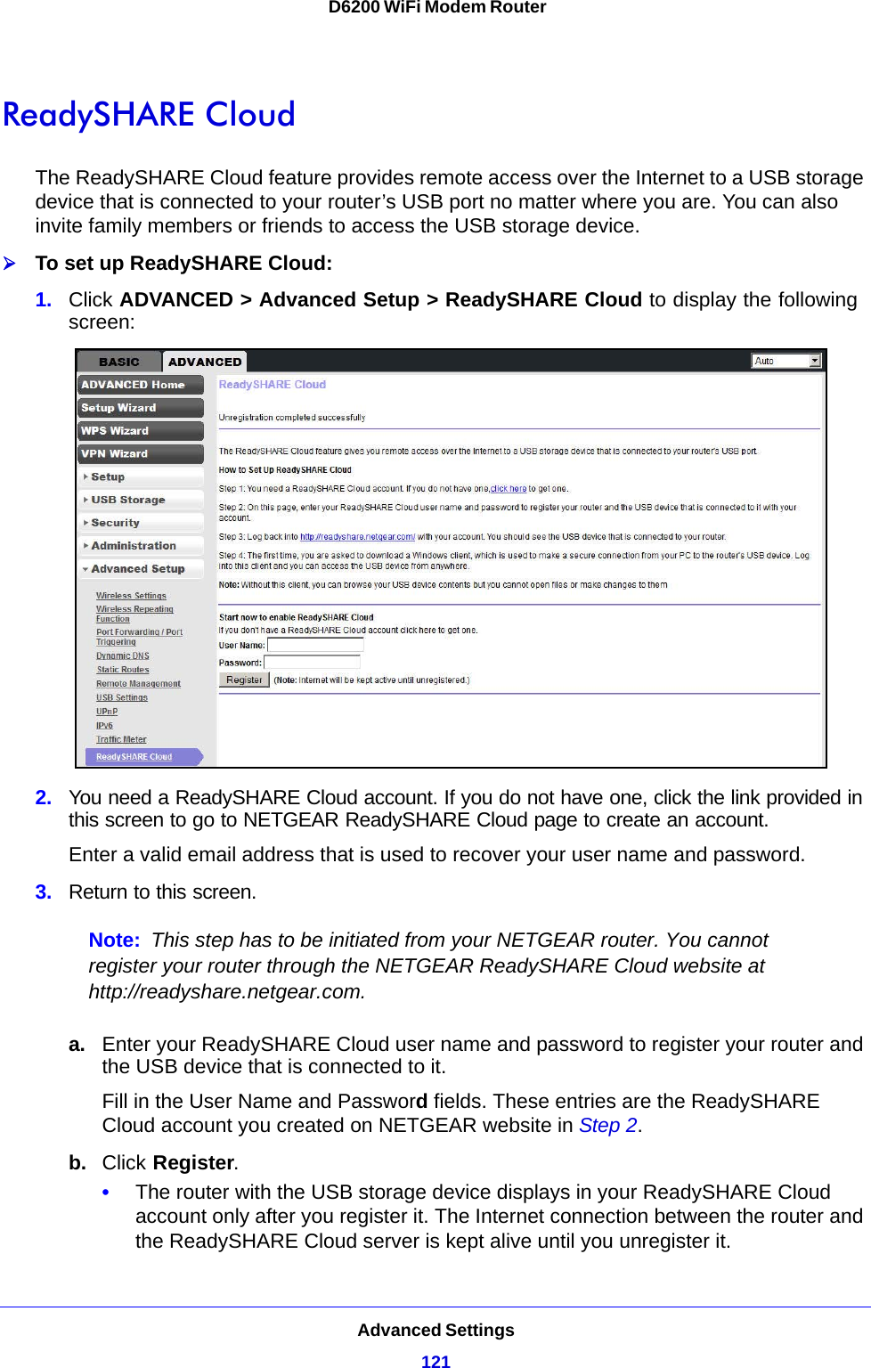
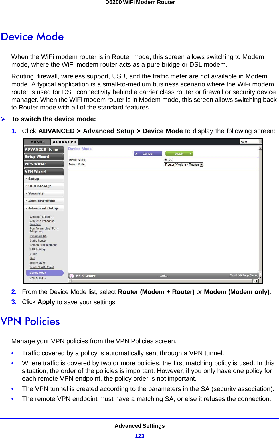
User manual II


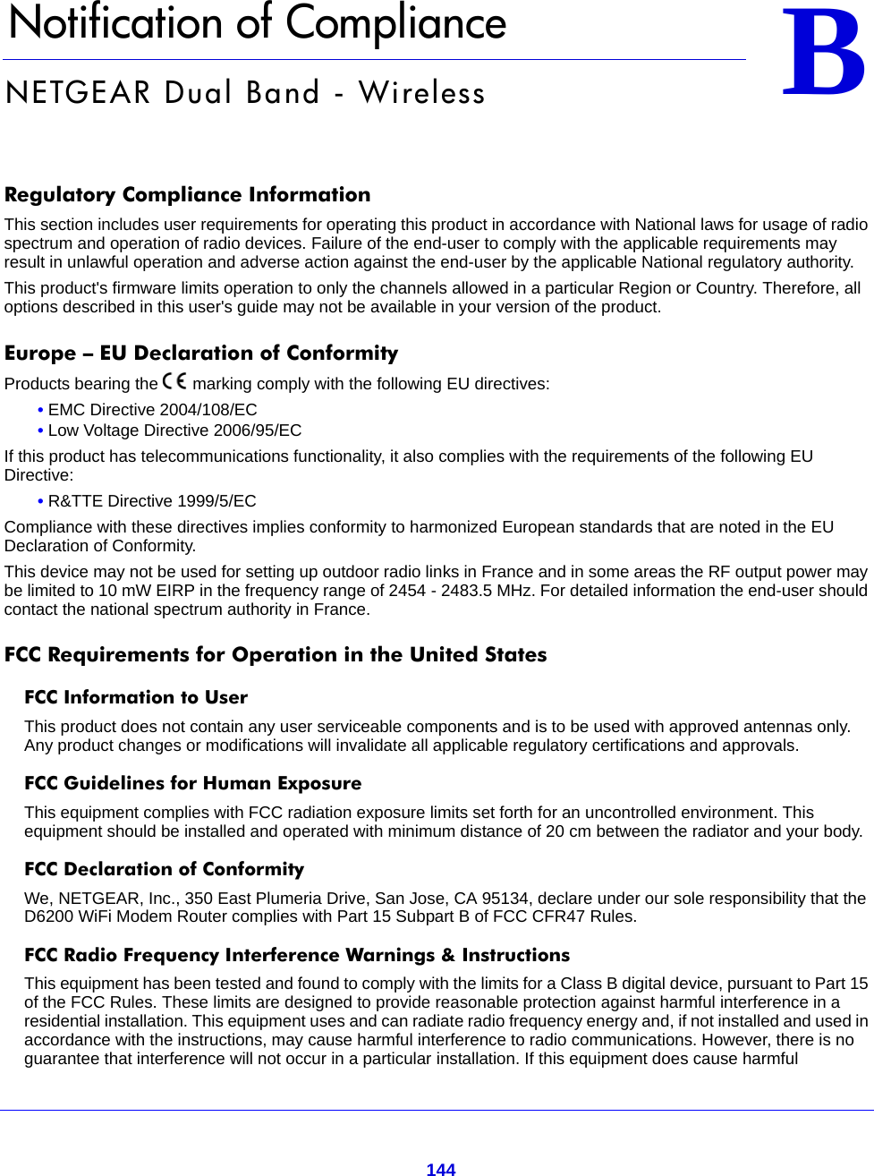
![Notification of Compliance145D6200 WiFi Modem Routerinterference to radio or television reception, which can be determined by turning the equipment off and on, the user is encouraged to try to correct the interference by one or more of the following methods:• Reorient or relocate the receiving antenna.• Increase the separation between the equipment and the receiver.• Connect the equipment into an electrical outlet on a circuit different from that which the radio receiver is connected.• Consult the dealer or an experienced radio/TV technician for help.FCC Caution• Any changes or modifications not expressly approved by the party responsible for compliance could void the user's authority to operate this equipment. • This device complies with Part 15 of the FCC Rules. Operation is subject to the following two conditions: (1) This device may not cause harmful interference, and (2) this device must accept any interference received, including interference that may cause undesired operation. • For product available in the USA market, only channel 1~11 can be operated. Selection of other channels is not possible.• This device and its antenna(s) must not be co-located or operation in conjunction with any other antenna or transmitter.Canadian Department of Communications Radio Interference RegulationsThis digital apparatus (D6200 WiFi Modem Router) does not exceed the Class B limits for radio-noise emissions from digital apparatus as set out in the Radio Interference Regulations of the Canadian Department of Communications.This Class [B] digital apparatus complies with Canadian ICES-003.Cet appareil numérique de la classe [B] est conforme à la norme NMB-003 du Canada.For product available in the USA/Canada market, only channel 1~11 can be operated. Selection of other channels is not possible.Pour les produits disponibles aux États-Unis / Canada du marché, seul le canal 1 à 11 peuvent être exploités. Sélection d'autres canaux n'est pas possible.This device and its antenna(s) must not be co-located or operation in conjunction with any other antenna or transmitter.Cet appareil et son antenne (s) ne doit pas être co-localisés ou fonctionnement en association avec une autre antenne ou transmetteur.The device could automatically discontinue transmission in case of absence of information to transmit, or operational failure. Note that this is not intended to prohibit transmission of control or signaling information or the use of repetitive codes where required by the technology.Le dispositif pourrait automatiquement cesser d'émettre en cas d'absence d'informations à transmettre, ou une défaillance opérationnelle. Notez que ce n'est pas l'intention d'interdire la transmission des informations de contrôle ou de signalisation ou l'utilisation de codes répétitifs lorsque requis par la technologie.The maximum antenna gain permitted for devices in the band 5725-5825 MHz shall comply with the e.i.r.p. limits specified for point-to-point and non point-to-point operation as appropriate.Le gain maximal d’antenne permis (pour les dispositifs utilisant la bande 5725-5825 MHz) doit se conformer à la limite de p.i.r.e. spécifiée pour l’exploitation point à point et non point à point, selon le cas.Industry CanadaThis device complies with RSS-210 of the Industry Canada Rules. Operation is subject to the following two conditions: (1) This device may not cause harmful interference, and (2) this device must accept any interference received, including interference that may cause undesired operation.IMPORTANT NOTE: Radiation Exposure Statement:This equipment complies with IC radiation exposure limits set forth for an uncontrolled environment. This equipment should be installed and operated with minimum distance 20cm between the radiator & your body.](https://usermanual.wiki/Netgear-orporated/12400216.User-manual-II/User-Guide-1894967-Page-50.png)