Netgear orporated 12400216 D6200 WiFi Modem Router User Manual D6200 WiFi Modem Router
Netgear Incorporated D6200 WiFi Modem Router D6200 WiFi Modem Router
Contents
- 1. Users manual I
- 2. Users manual II
- 3. User manual I
- 4. User manual II
User manual II

96
9
9. Advanced Settings
Fine-tuning your network
This chapter describes the advanced features of your WiFi modem router. The information is for
users with a solid understanding of networking concepts who want to set the WiFi modem router
up for unique situations such as when remote access from the Internet by IP or domain name is
needed.
This chapter includes the following sections:
•Advanced Wireless Settings
•Wireless Repeating Function (WDS)
•Port Forwarding and Triggering
•Set Up Port Forwarding to Local Servers
•Set Up Port Triggering
•Dynamic DNS
•Static Routes
•Remote Management
•USB Settings
•Universal Plug and Play
•IPv6
•Traffic Meter
•ReadySHARE Cloud
•Device Mode
•VPN Policies
Advanced Settings
97
D6200 WiFi Modem Router
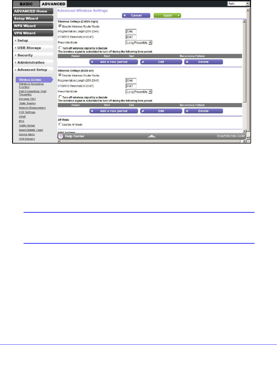
Advanced Wireless Settings
Select ADVANCED > Advanced Setup > Wireless Settings to display the Advanced
Wireless Settings screen:
The following settings are available in this screen:
•Enable Wireless Router Radio. You can completely turn off the wireless portion of the
WiFi modem router by clearing this check box. Select this check box again to enable the
wireless portion of the WiFi modem router. When the wireless radio is disabled, other
members of your household can use the WiFi modem router by connecting their
computers to the WiFi modem router with an Ethernet cable.
Note: The Fragmentation Length, CTS/RTS Threshold, and Preamble
Mode options are reserved for wireless testing and advanced
configuration only. Do not change these settings.
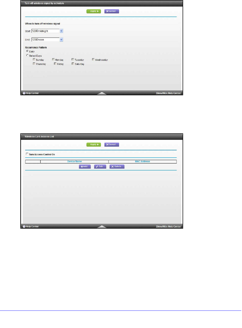
•Turn off wireless signal by schedule. From the Advanced Wireless Settings screen
(with the Enable Wireless Router Radio check box selected for the radio band you want
to configure), click the Add a new period button to display the Turn off wireless signal by
schedule screen.
Advanced Settings
98
D6200 WiFi Modem Router
You can use this feature to turn off the wireless signal from your WiFi modem router at
times when you do not need a wireless connection. For example, you could turn it off for
the weekend if you leave town.
•WPS Settings. You can add WPS devices to your network.
•AP Mode. You can make the D6200 function as an access point.
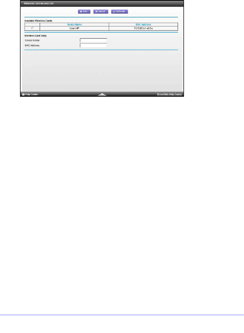
•Wireless Card Access List. From the Advanced Wireless Settings screen, click the Set
Up Access List button to display the Wireless Card Access List screen.
Advanced Settings
99
D6200 WiFi Modem Router
From the Wireless Card Access List screen, click Add to display the Wireless Card
Access Setup screen. On this screen, you can restrict access to your network to specific
devices based on their MAC address.
Advanced Settings
100
D6200 WiFi Modem Router
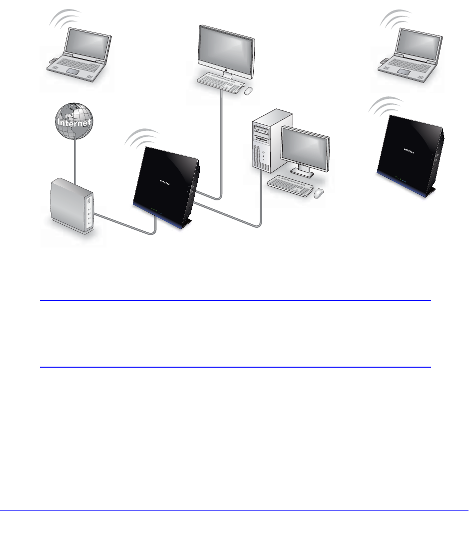
Wireless Repeating Function (WDS)
You can set the WiFi Modem Router up to be used as a wireless access point (AP). Doing
this setup enables the WiFi modem router to act as a wireless repeater. A wireless repeater
connects to another wireless WiFi modem router as a client where the network to which it
connects becomes the ISP service.
Wireless repeating is a type of Wireless Distribution System (WDS). A WDS allows a wireless
network to be expanded through multiple access points instead of using a wired backbone to
link them. The following figure shows a wireless repeating scenario.
Repeater
Base station
access point
access point
Figure 12. Wireless repeating scenario
Note: If you use the wireless repeating function, you need to select either
WEP or None as a security option in the Wireless Settings screen.
The WEP option displays only if you select the wireless mode Up to
54 Mbps in the Wireless Settings screen.
Wireless Base Station. The WiFi modem router acts as the parent access point, bridging
traffic to and from the child repeater access point, as well as handling wireless and wired
local computers. To configure this mode, you have to know the MAC address of the child
repeater access point.
Wireless Repeater. The WiFi modem router sends all traffic from its local wireless or wired
computers to a remote access point. To configure this mode, you have to know the MAC
address of the remote parent access point.
Advanced Settings
101
D6200 WiFi Modem Router
The D6200 WiFi modem router is always in dual-band concurrent mode, unless you turn off
one radio. If you enable the wireless repeater in either radio band, the wireless base station
or wireless repeater cannot be enabled in the other radio band. However, if you enable the
wireless base station in either radio band and use the other radio band as a wireless WiFi
modem router or wireless base station, dual-band concurrent mode is not affected.
For you to set up a wireless network with WDS, the following conditions have to be met for
both access points:
•Both access points have to use the same SSID, wireless channel, and encryption mode.
•Both access points have to be on the same LAN IP subnet. That is, all the access point
LAN IP addresses are in the same network.
•All LAN devices (wired and wireless computers) have to be configured to operate in the
same LAN network address range as the access points.
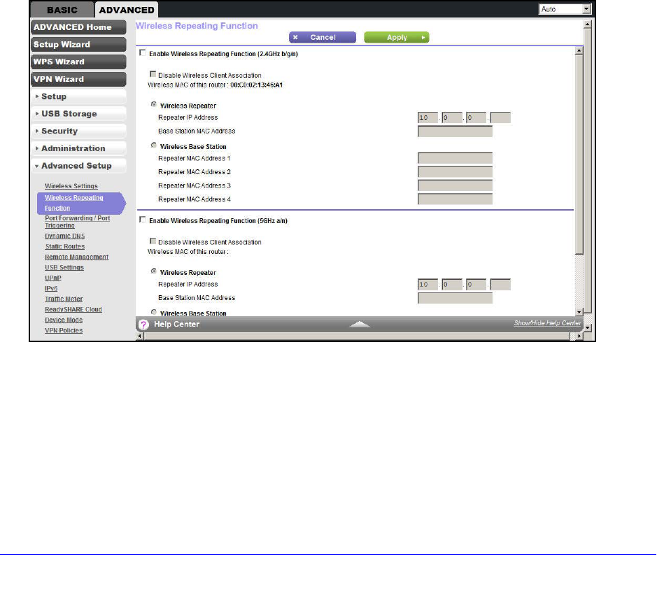
Wireless Repeating Function
Select ADVANCED > Advanced Setup > Wireless Repeating Function to view or change
wireless repeater settings for the WiFi modem router.
•Enable Wireless Repeating Function. Select the check box for the 2.4 GHz or 5 GHz
network to use the wireless repeating function.
•Disable Wireless Client Association. If your WiFi modem router is the repeater,
selecting this check box means that wireless clients cannot associate with it. Only LAN
client associations are allowed.
-If you are setting up a point-to-point bridge, select this check box.
-If you want all client traffic to go through the other access point (repeater with wireless
client association), leave this check box cleared.

Advanced Settings
102
D6200 WiFi Modem Router
•Wireless MAC of this router. This field displays the MAC address for your WiFi modem
router for your reference. You need to enter this MAC address in the corresponding
Wireless Repeating Function screen of the other access point you are using.
•Wireless Repeater. If your WiFi modem router is the repeater, select this radio button.
Repeater IP Address. If your WiFi modem router is the repeater, enter the IP address of
the other access point.
Base Station MAC Address. If your WiFi modem router is the repeater, enter the MAC
address for the access point that is the base station.
•Wireless Base Station. If your WiFi modem router is the base station, select this radio
button.
Disable Wireless Client Association. If your WiFi modem router is the base station,
selecting this check box means that wireless clients cannot associate with it. Only LAN
client associations are allowed.
Repeater MAC Address (1 through 4). If your WiFi modem router is the base station, it
can act as the “parent” of up to four other access points. Enter the MAC addresses of the
other access points in these fields.
Set Up the Base Station
The wireless repeating function works only in hub and spoke mode. The units cannot be
daisy-chained. You have to know the wireless settings for both units. You have to know the
MAC address of the remote unit. First, set up the base station and then set up the repeater.
To set up the base station:
1. Set up both units with the same wireless settings (SSID, mode, channel, and security).
The wireless security option has to be set to None or WEP.
2. Select ADVANCED > Advanced Setup > Wireless Repeating Function to display the
Wireless Repeating Function screen.
3. Depending on the frequency you want to use, select the Enable Wireless Repeating
Function check box and select the Wireless Base Station radio button.
4. Enter the MAC address for one or more repeater units.
5. Click Apply to save your changes.
Set Up a Repeater Unit
Use a wired Ethernet connection to set up the repeater unit to avoid conflicts with the wireless
connection to the base station.

Advanced Settings
103
D6200 WiFi Modem Router
Note: If you are using the D6200 base station with a non-NETGEAR WiFi
modem router as the repeater, you might need to change more
configuration settings. In particular, you should disable the DHCP
server function on the wireless repeater AP.
To configure the WiFi modem router as a repeater unit:
1. Log in to the WiFi modem router that is the repeater. Select BASIC > Wireless Settings
and verify that the wireless settings match the base unit exactly. The wireless security
option has to be set to WEP or None.
2. Select ADVANCED > Advanced Setup > Wireless Repeating Function, and select the
Enable Wireless Repeating Function check box and the Wireless Repeater radio button.
3. Complete the Repeater IP Address field. This IP address has to be in the same subnet as
the base station, but different from the LAN IP of the base station.
4. Click Apply to save your changes.
5. Verify connectivity across the LANs.
A computer on any wireless or wired LAN segment of the WiFi modem router should be
able to connect to the Internet or share files and printers with other wireless or wired
computer or server connected to the other access point.
Port Forwarding and Triggering
By default, the WiFi modem router blocks inbound traffic from the Internet to your computers
except replies to your outbound traffic. You might need to create exceptions to this rule for
these purposes:
•To allow remote computers on the Internet to access a server on your local network.
•To allow certain applications and games to work correctly when their replies are not
recognized by your WiFi modem router.
Your WiFi modem router provides two features for creating these exceptions: port forwarding
and port triggering. The next sections provide background information to help you understand
how port forwarding and port triggering work, and the differences between the two.
Remote Computer Access Basics
When a computer on your network needs to access a computer on the Internet, your
computer sends your WiFi modem router a message containing the source and destination
address and process information. Before forwarding your message to the remote computer,
your WiFi modem router has to modify the source information and create and track the
communication session so that replies can be routed back to your computer.
Here is an example of normal outbound traffic and the resulting inbound responses:

Advanced Settings
104
D6200 WiFi Modem Router
1. You open a browser, and your operating system assigns port number 5678 to this
browser session.
2. You type http://www.example.com into the URL field, and your computer creates a web page
request message with the following address and port information. The request message is
sent to your WiFi modem router.
Source address. Your computer’s IP address.
Source port number. 5678, which is the browser session.
Destination address. The IP address of www.example.com, which your computer finds
by asking a DNS server.
Destination port number. 80, which is the standard port number for a web server
process.
3. Your WiFi modem router creates an entry in its internal session table describing this
communication session between your computer and the web server at www.example.com.
Before sending the web page request message to www.example.com, your WiFi modem
router stores the original information and then modifies the source information in the request
message, performing Network Address Translation (NAT):
•The source address is replaced with your WiFi modem router’s public IP address.
This requirement is necessary because your computer uses a private IP address that
is not globally unique and cannot be used on the Internet.
•The source port number is changed to a number chosen by the WiFi modem router,
such as 33333. This requirement is necessary because two computers could
independently be using the same session number.
Your WiFi modem router then sends this request message through the Internet to the web
server at www.example.com.
4. The web server at www.example.com composes a return message with the requested web
page data. The return message contains the following address and port information. The
web server then sends this reply message to your WiFi modem router.
Source address. The IP address of www.example.com.
Source port number. 80, which is the standard port number for a web server process.
Destination address. The public IP address of your WiFi modem router.
Destination port number. 33333.
5. Upon receiving the incoming message, your WiFi modem router checks its session table to
determine whether an active session for port number 33333 exists. Finding an active
session, the WiFi modem router then modifies the message to restore the original address
information replaced by NAT. Your WiFi modem router sends this reply message to your
computer, which displays the web page from www.example.com. The message now
contains the following address and port information.
Source address. The IP address of www.example.com.
Source port number. 80, which is the standard port number for a web server process.
Destination address. Your computer’s IP address.

Advanced Settings
105
D6200 WiFi Modem Router
Destination port number. 5678, which is the browser session that made the initial
request.
6. When you finish your browser session, your WiFi modem router eventually detects a period
of inactivity in the communications. Your WiFi modem router then removes the session
information from its session table, and incoming traffic is no longer accepted on port number
33333.
Port Triggering to Open Incoming Ports
In the preceding example, requests are sent to a remote computer by your WiFi modem
router from a particular service port number, and replies from the remote computer to your
WiFi modem router are directed to that port number. If the remote server sends a reply to a
different port number, your WiFi modem router does not recognize it and discards it.
However, some application servers (such as FTP and IRC servers) send replies to multiple
port numbers. Using the port triggering function of your WiFi modem router, you can tell the
WiFi modem router to open more incoming ports when a particular outgoing port originates a
session.
An example is Internet Relay Chat (IRC). Your computer connects to an IRC server at
destination port 6667. The IRC server not only responds to your originating source port, but
also sends an “identify” message to your computer on port 113. Using port triggering, you can
tell the WiFi modem router, “When you initiate a session with destination port 6667, you have
to also allow incoming traffic on port 113 to reach the originating computer.” Using steps
similar to the preceding example, the following sequence shows the effects of the port
triggering rule you have defined:
1. You open an IRC client program to start a chat session on your computer.
2. Your IRC client composes a request message to an IRC server using a destination port
number of 6667, the standard port number for an IRC server process. Your computer then
sends this request message to your WiFi modem router.
3. Your WiFi modem router creates an entry in its internal session table describing this
communication session between your computer and the IRC server. Your WiFi modem
router stores the original information, performs Network Address Translation (NAT) on the
source address and port, and sends this request message through the Internet to the IRC
server.
4. Noting your port triggering rule and having observed the destination port number of 6667,
your WiFi modem router creates an additional session entry to send any incoming port 113
traffic to your computer.
5. The IRC server sends a return message to your WiFi modem router using the
NAT-assigned source port (as in the previous example, say port 33333) as the destination
port. The IRC server also sends an identify message to your WiFi modem router with
destination port 113.
6. Upon receiving the incoming message to destination port 33333, your WiFi modem router
checks its session table to determine whether an active session for port number 33333
exists. Finding an active session, the WiFi modem router restores the original address
information replaced by NAT and sends this reply message to your computer.
7. Upon receiving the incoming message to destination port 113, your WiFi modem router
checks its session table and learns that an active session exists for port 113 associated with

Advanced Settings
106
D6200 WiFi Modem Router
your computer. The WiFi modem router replaces the message’s destination IP address with
your computer’s IP address and forwards the message to your computer.
8. When you finish your chat session, your WiFi modem router eventually senses a period of
inactivity in the communications. The WiFi modem router then removes the session
information from its session table, and incoming traffic is no longer accepted on port
numbers 33333 or 113.
To configure port triggering, you need to know which inbound ports the application needs.
Also, you need to know the number of the outbound port that triggers the opening of the
inbound ports. You can usually determine this information by contacting the publisher of the
application or user groups or newsgroups.
Note: Only one computer at a time can use the triggered application.
Port Forwarding to Permit External Host Communications
In both of the preceding examples, your computer initiates an application session with a
server computer on the Internet. However, you might need to allow a client computer on the
Internet to initiate a connection to a server computer on your network. Normally, your WiFi
modem router ignores any inbound traffic that is not a response to your own outbound traffic.
You can configure exceptions to this default rule by using the port forwarding feature.
A typical application of port forwarding can be shown by reversing the client-server
relationship from the previous web server example. In this case, a remote computer’s
browser needs to access a web server running on a computer in your local network. Using
port forwarding, you can tell the WiFi modem router, “When you receive incoming traffic on
port 80 (the standard port number for a web server process), forward it to the local computer
at 192.168.1.123.” The following sequence shows the effects of the port forwarding rule you
have defined:
1. The user of a remote computer opens a browser and requests a web page from
www.example.com, which resolves to the public IP address of your WiFi modem router.
The remote computer composes a web page request message with the following
destination information:
Destination address. The IP address of www.example.com, which is the address of your
WiFi modem router.
Destination port number. 80, which is the standard port number for a web server
process.
The remote computer then sends this request message through the Internet to your WiFi
modem router.
2. Your WiFi modem router receives the request message and looks in its rules table for any
rules covering the disposition of incoming port 80 traffic. Your port forwarding rule specifies
that incoming port 80 traffic should be forwarded to local IP address 192.168.1.123.
Therefore, your WiFi modem router modifies the destination information in the request
message:

Advanced Settings
107
D6200 WiFi Modem Router
The destination address is replaced with 192.168.1.123.
Your WiFi modem router then sends this request message to your local network.
3. Your web server at 192.168.1.123 receives the request and composes a return message
with the requested web page data. Your web server then sends this reply message to your
WiFi modem router.
4. Your WiFi modem router performs Network Address Translation (NAT) on the source IP
address, and sends this request message through the Internet to the remote computer,
which displays the web page from www.example.com.
To configure port forwarding, you need to know which inbound ports the application needs.
Usually you can determine this information by contacting the publisher of the application or
the relevant user groups and newsgroups.
How Port Forwarding Differs from Port Triggering
The following points summarize the differences between port forwarding and port triggering:
•Port triggering can be used by any computer on your network, although only one
computer can use it at a time.
•Port forwarding is configured for a single computer on your network.
•Port triggering requires that you know the computer’s IP address in advance. The IP
address is captured automatically.
•Port forwarding requires that you specify the computer’s IP address during configuration,
and the IP address can never change.
•Port triggering requires specific outbound traffic to open the inbound ports, and the
triggered ports are closed after a period of no activity.
•Port forwarding is always active and does not need to be triggered.
Set Up Port Forwarding to Local Servers
Using the port forwarding feature, you can allow certain types of incoming traffic to reach
servers on your local network. For example, you might want to make a local web server, FTP
server, or game server visible and available to the Internet.
Use the Port Forwarding/Port Triggering screen to configure the WiFi modem router to
forward specific incoming protocols to computers on your local network. In addition to servers
for specific applications, you can also specify a default DMZ server to which all other
incoming protocols are forwarded.
Before starting, you need to determine which type of service, application, or game you want
to provide, and the local IP address of the computer that provides the service. The server
computer has to always have the same IP address.
Advanced Settings
108
D6200 WiFi Modem Router
To set up port forwarding:
Tip: To ensure that your server computer always has the same IP address,
use the reserved IP address feature of your WiFi Modem Router.
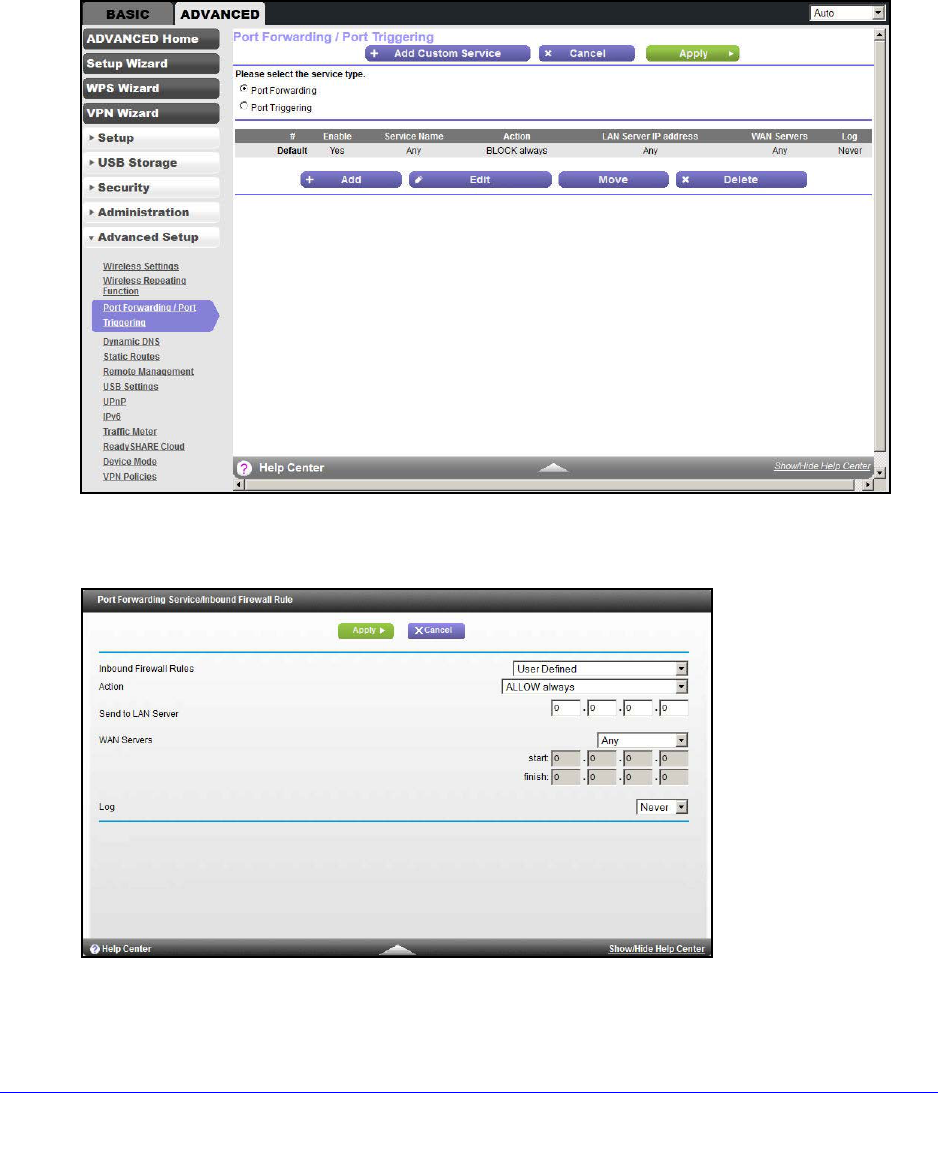
1. Select ADVANCED > Advanced Setup > Port Forwarding/Port Triggering to display
the following screen:
Port Forwarding is selected as the service type.
2. Click Add to display the following screen:
3. From the Service list, select the service or game that you host on your network. If the service
does not appear in the list, see Add a Custom Service on page 109.
Advanced Settings
109
D6200 WiFi Modem Router
4. From the Action list, select the action that you want.
5. In the Send to LAN Server field, enter the last digit of the IP address of your local computer
that provides this service.
6. Click Apply. The service appears in the list in the screen.
Add a Custom Service
To define a service, game, or application that does not appear in the Service Name list, you
have to first determine which port number or range of numbers is used by the application.
You can usually determine this information by contacting the publisher of the application or
user groups or newsgroups.
To add a custom service:
1. Select ADVANCED > Advanced Setup > Port Forwarding/Port Triggering.
2. Select Port Forwarding as the service type.
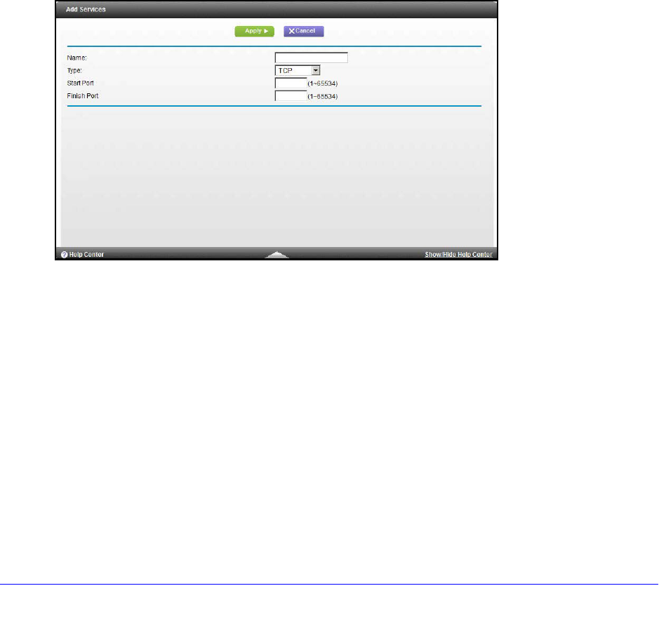
3. Click the Add Custom Service button to display the following screen:
4. In the Name field, enter a descriptive name.
5. In the Type list, select the protocol. If you are unsure, select TCP/UDP.
6. In the Start Port field, enter the beginning port number.
•If the application uses a single port, enter the same port number in the End Port field.
•If the application uses a range of ports, enter the ending port number of the range in
the End Port field.
7. Click Apply. The service appears in the list in the Port Forwarding/Port Triggering screen.
Edit or Delete a Port Forwarding Entry
To edit or delete a port forwarding entry:
1. Select ADVANCED > Advanced Setup > Port Forwarding/Port Triggering.
2. In the table, select the radio button next to the service name.

Advanced Settings
110
D6200 WiFi Modem Router
3. Click Edit Service or Delete Service.
Application Example: Making a Local Web Server Public
If you host a web server on your local network, you can use port forwarding to allow web
requests from anyone on the Internet to reach your web server.
To make a local web server public:
1. Assign your web server either a fixed IP address or a dynamic IP address using DHCP
address reservation. In this example, your WiFi modem router always gives your web
server an IP address of 192.168.1.33.
2. In the Port Forwarding/Port Triggering screen, configure the WiFi modem router to forward
the HTTP service to the local address of your web server at 192.168.1.33. HTTP (port 80) is
the standard protocol for web servers.
3. (Optional) Register a host name with a Dynamic DNS service, and configure your WiFi
modem router to use the name as described in Dynamic DNS on page 112. To access your
web server from the Internet, a remote user has to know the IP address that has been
assigned by your ISP. However, if you use a Dynamic DNS service, the remote user can
reach your server by a user-friendly Internet name, such as mynetgear.dyndns.org.
Set Up Port Triggering
Port triggering is a dynamic extension of port forwarding that is useful in these cases:
•More than one local computer needs port forwarding for the same application (but not
simultaneously).
•An application needs to open incoming ports that are different from the outgoing port.
When port triggering is enabled, the WiFi modem router monitors outbound traffic looking for
a specified outbound “trigger” port. When the WiFi modem router detects outbound traffic on
that port, it remembers the IP address of the local computer that sent the data. The WiFi
modem router then temporarily opens the specified incoming port or ports, and forwards
incoming traffic on the triggered ports to the triggering computer.
While port forwarding creates a static mapping of a port number or range to a single local
computer, port triggering can dynamically open ports to any computer that needs them and
can close the ports when they are no longer needed.
Note: If you use applications such as multiplayer gaming, peer-to-peer
connections, real-time communications such as instant messaging,
or remote assistance (a feature in Windows XP), you should also
enable Universal Plug and Play (UPnP) according to the instructions
in Universal Plug and Play on page 117.
Advanced Settings
111
D6200 WiFi Modem Router
To set up port triggering, you need to know which inbound ports the application needs. Also,
you need to know the number of the outbound port that triggers the opening of the inbound
ports. You can usually determine this information by contacting the publisher of the
application or user groups or newsgroups.
To set up port triggering:
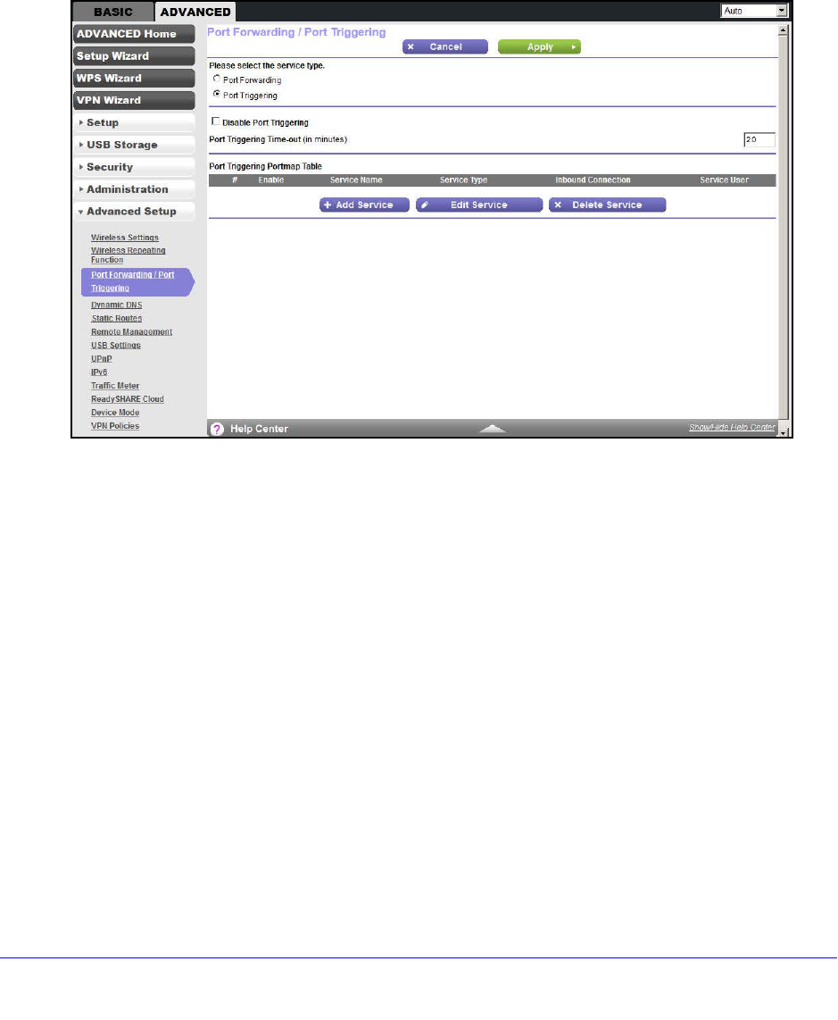
1. Select ADVANCED > Advanced Setup > Port Forwarding/Port Triggering.
2. Select the Port Triggering radio button to display the port triggering information.
3. Clear the Disable Port Triggering check box if it is selected.
Note: If the Disable Port Triggering check box is selected after you configure
port triggering, port triggering is disabled. However, any port triggering
configuration information you added to the WiFi modem router is retained even
though it is not used.
4. In the Port Triggering Timeout field, enter a value up to 9999 minutes.
This value controls the inactivity timer for the designated inbound ports. The inbound
ports close when the inactivity time expires. This closure is required because the WiFi
modem router cannot be sure when the application has terminated.
Advanced Settings
112
D6200 WiFi Modem Router
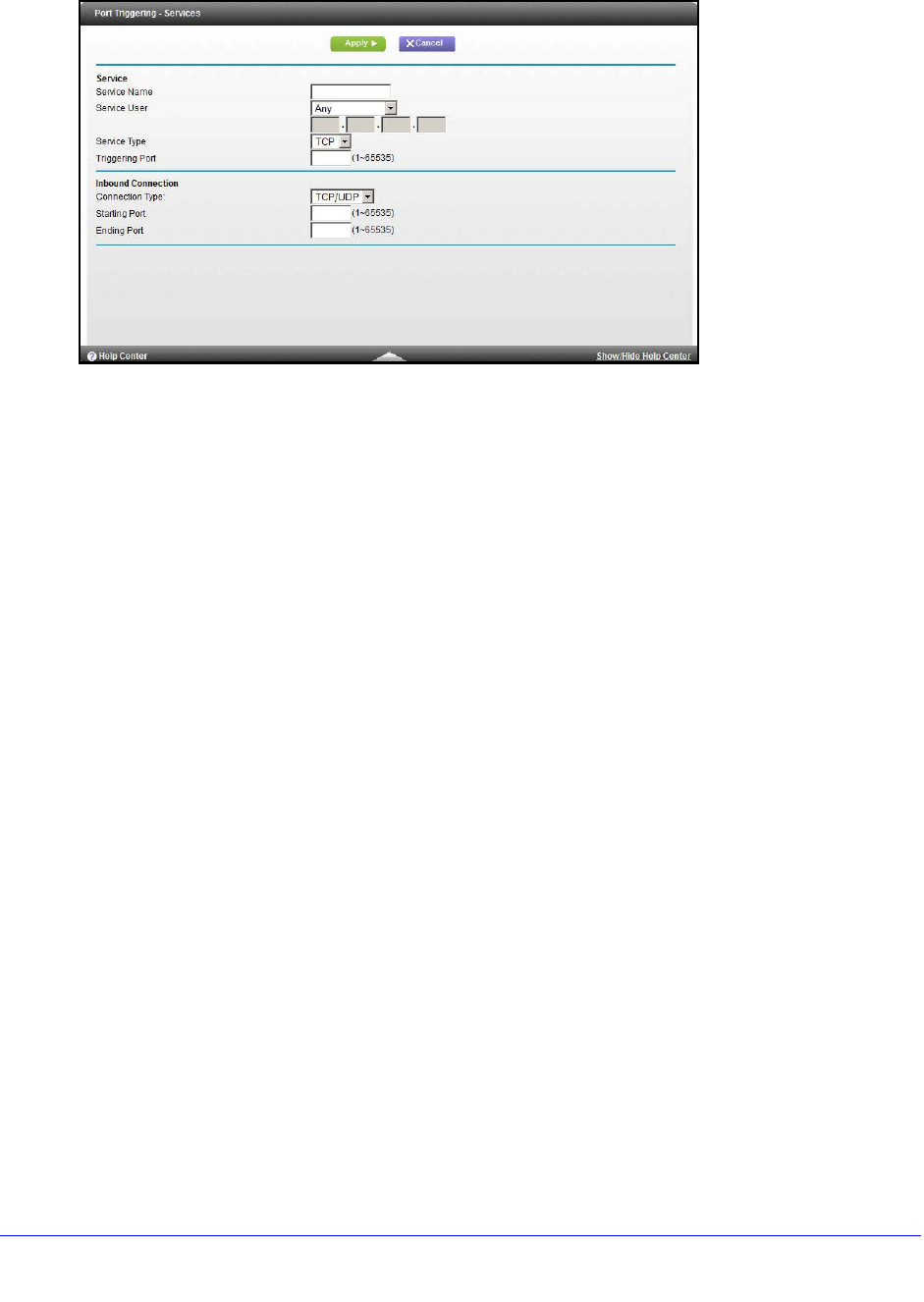
5. Click Add Service to display the following screen:
6. In the Service Name field, type a descriptive service name.
7. In the Service User list, select Any (the default) to allow this service to be used by any
computer on the Internet. Otherwise, select Single address, and enter the IP address of
one computer to restrict the service to a particular computer.
8. Select the service type, either TCP or UDP or both (TCP/UDP). If you are not sure, select
TCP/UDP.
9. In the Triggering Port field, enter the number of the outbound traffic port that causes the
inbound ports to be opened.
10. Enter the inbound connection port information in the Service Type, Starting Port, and Ending
Port fields.
11. Click Apply. The service appears in the Port Triggering Portmap table.
Dynamic DNS
If your Internet service provider (ISP) gave you a permanently assigned IP address, you can
register a domain name and have that name linked with your IP address by public Domain
Name Servers (DNS). However, if your Internet account uses a dynamically assigned IP
address, you do not know in advance what your IP address is, and the address can change
frequently. In this case, you can use a commercial Dynamic DNS service. This type of service
lets you register your domain to their IP address and forwards traffic directed at your domain
to your frequently changing IP address.
If your ISP assigns a private WAN IP address (such as 192.168.x.x or 10.x.x.x), the Dynamic
DNS service does not works because private addresses are not routed on the Internet.
Your WiFi modem router contains a client that can connect to the Dynamic DNS service
provided by DynDNS.org. First visit their website at http://www.dyndns.org and obtain an
account and host name that you configure in the WiFi modem router. Then, whenever your
ISP-assigned IP address changes, your WiFi modem router automatically contacts the
Dynamic DNS service provider, logs in to your account, and registers your new IP address. If
Advanced Settings
113
D6200 WiFi Modem Router
your host name is hostname, for example, you can reach your WiFi modem router at
http://hostname.dyndns.org.
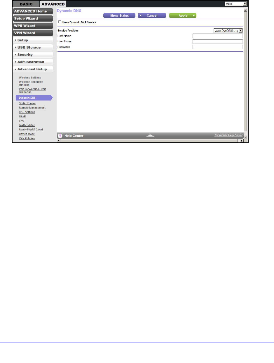
On the Advanced tab, select Advanced Setup > Dynamic DNS to display the following
screen:
To set up Dynamic DNS:
1. Register for an account with one of the Dynamic DNS service providers whose
addresses appear in the Service Provider list.
2. Select the Use a Dynamic DNS Service check box.
3. Select the address of your Dynamic DNS service provider. For example, for DynDNS.org,
select www.dyndns.org.
4. Type the host name (or domain name) that your Dynamic DNS service provider gave you.
5. Type the user name for your Dynamic DNS account. This name is the name that you use to
log in to your account, not your host name.
6. Type the password (or key) for your Dynamic DNS account.
7. Click Apply to save your configuration.
Static Routes
Static routes provide more routing information to your WiFi modem router. Under usual
circumstances, the WiFi modem router has adequate routing information after it has been
configured for Internet access, and you do not need to configure more static routes. You have
to configure static routes only for unusual cases such as multiple WiFi modem routers or
multiple IP subnets on your network.
As an example of when a static route is needed, consider the following case:
Advanced Settings
114
D6200 WiFi Modem Router
•Your primary Internet access is through a cable modem to an ISP.
•You have an ISDN WiFi modem router on your home network for connecting to the
company where you are employed. This WiFi modem router’s address on your LAN is
192.168.1.100.
•Your company’s network address is 134.177.0.0.
When you first configured your WiFi modem router, two implicit static routes were created. A
default route was created with your ISP as the gateway, and a second static route was
created to your local network for all 192.168.1.x addresses. With this configuration, if you
attempt to access a device on the 134.177.0.0 network, your WiFi modem router forwards
your request to the ISP. The ISP forwards your request to the company where you are
employed, and the request is likely to be denied by the company’s firewall.
In this case you have to define a static route, telling your WiFi modem router that 134.177.0.0
should be accessed through the ISDN WiFi modem router at 192.168.1.100. In this example:
•The Destination IP Address and IP Subnet Mask fields specify that this static route
applies to all 134.177.x.x addresses.
•The Gateway IP Address field specifies that all traffic for these addresses should be
forwarded to the ISDN WiFi modem router at 192.168.1.100.
•A metric value of 1 works since the ISDN WiFi modem router is on the LAN.
•Private is selected only as a precautionary security measure in case RIP is activated.
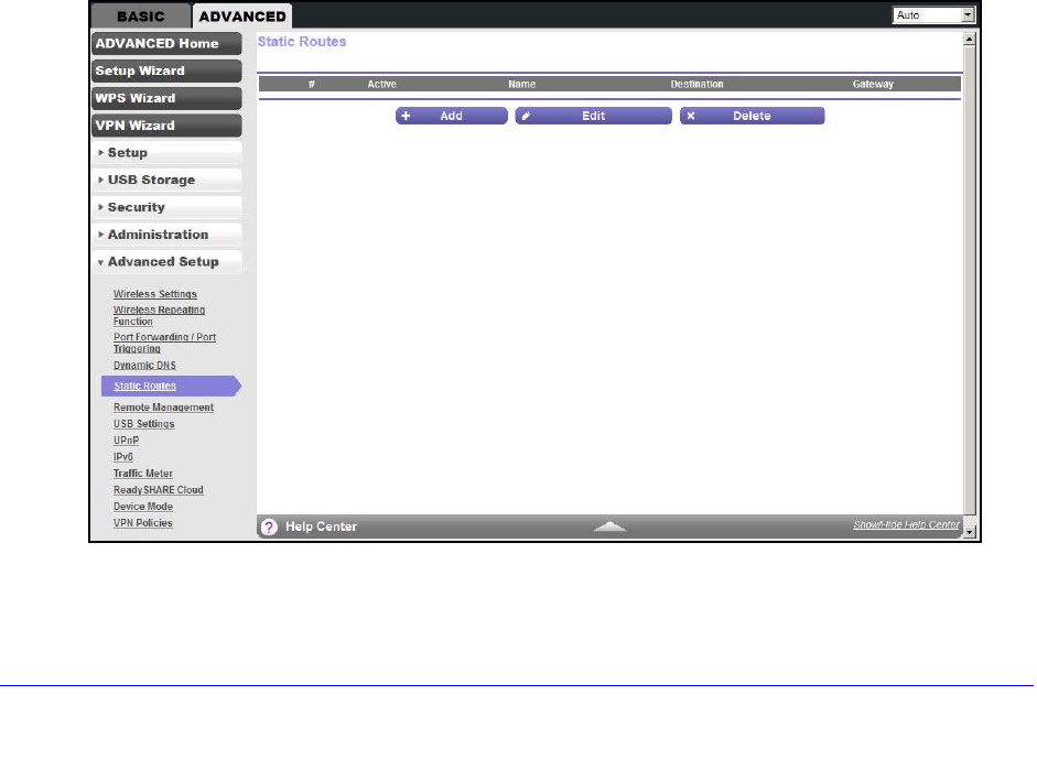
To set up a static route:
1. Select ADVANCED > Advanced Setup > Static Routes to display the following screen:
Advanced Settings
115
D6200 WiFi Modem Router
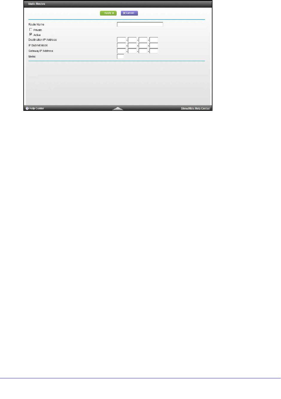
2. Click Add to display the following screen:
3. In the Route Name field, type a name for this static route (for identification purposes only).
4. Select the Private check box if you want to limit access to the LAN only. If Private is
selected, the static route is not reported in RIP.
5. Select the Active check box to make this route effective.
6. Type the IP address of the final destination.
7. Type the IP subnet mask for this destination. If the destination is a single host, type
255.255.255.255.
8. Type the gateway IP address, which has to be a WiFi modem router on the same LAN
segment as the WiFi Modem Router.
9. Type a number from 1 through 15 as the metric value.
This value represents the number of WiFi modem routers between your network and the
destination. Usually, a setting of 2 or 3 works, but if this link is a direct connection, set it to
1.
10. Click Apply to add the static route.
Advanced Settings
116
D6200 WiFi Modem Router
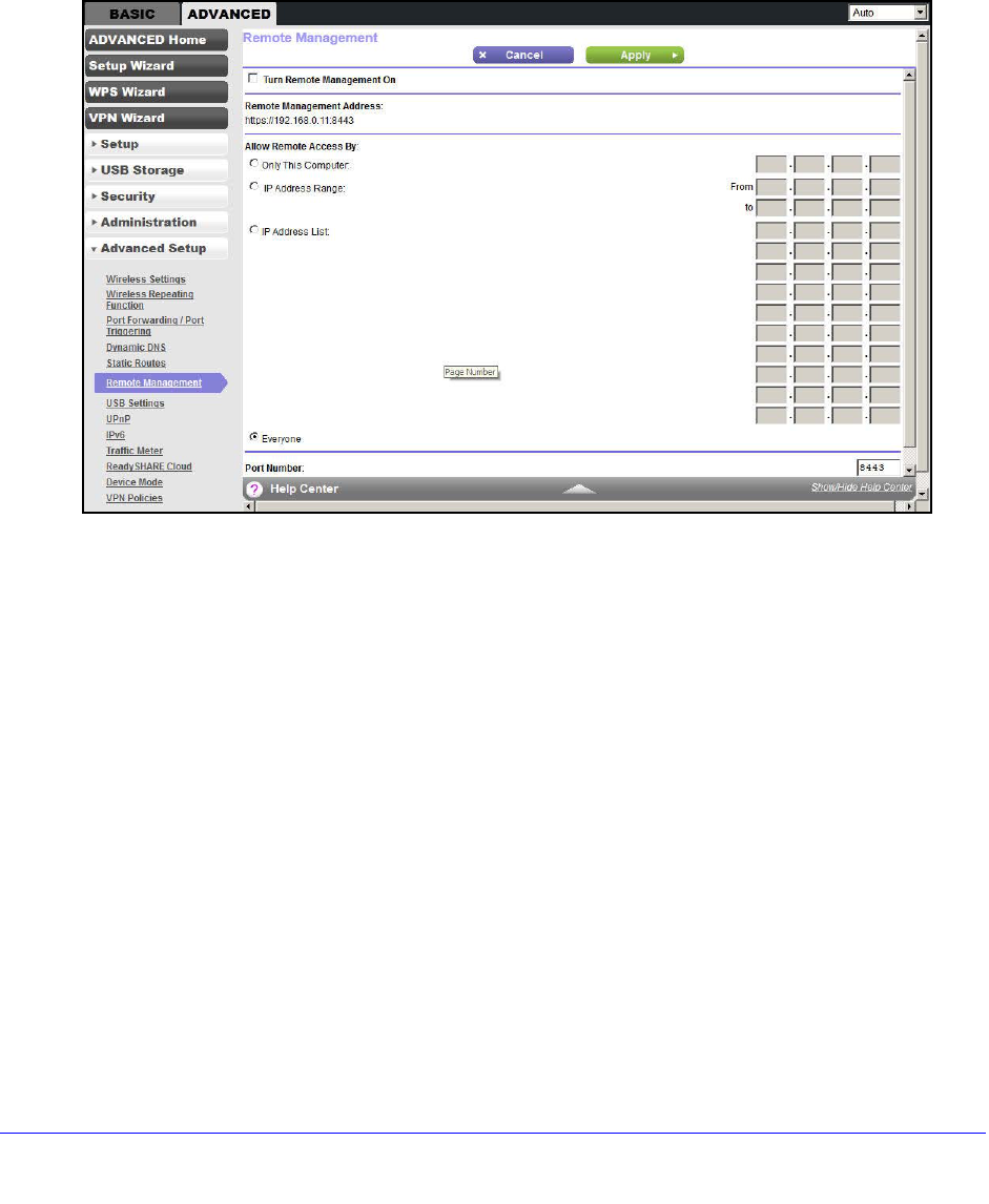
Remote Management
The remote management feature lets you upgrade or check the status of your WiFi Modem
Router over the Internet.
To set up remote management:
1. Select ADVANCED > Advanced Setup > Remote Management.
Note: Be sure to change the WiFi modem router’s default login password to a
secure password. The ideal password should contain no dictionary words from
any language and contain uppercase and lowercase letters, numbers, and
symbols. It can be up to 30 characters.
2. Select the Turn Remote Management On check box.
3. Under Allow Remote Access By, specify the external IP addresses allowed to access the
WiFi modem router’s remote web management interface.
Note: For enhanced security, restrict access to as few external IP addresses
as practical.
•To allow access from a single IP address on the Internet, select Only This Computer.
Enter the IP address that is allowed access.
•To allow access from a range of IP addresses on the Internet, select IP Address
Range. Enter a beginning and ending IP address to define the allowed range.
•To allow access from any IP address on the Internet, select Everyone.
4. Specify the port number for accessing the web management interface.

Advanced Settings
117
D6200 WiFi Modem Router
Normal web browser access uses the standard HTTP service port 80. For greater
security, enter a custom port number for the remote web management interface. Choose
a number from 1024 through 65535, but do not use the number of any common service
port. The default is 8080, which is a common alternate for HTTP.
5. Click Apply to have your changes take effect.
6. When accessing your WiFi modem router from the Internet, type your WiFi modem router’s
WAN IP address into your browser’s address or location field followed by a colon (:) and the
custom port number. For example, if your external address is 134.177.0.123 and you use
port number 8080, enter http://134.177.0.123:8080 in your browser.
USB Settings
For added security, the WiFi modem router can be set up to share only approved USB
devices. See Specify Approved USB Devices on page 70 for the procedure.
Universal Plug and Play
Universal Plug and Play (UPnP) helps devices, such as Internet appliances and computers,
to access the network and connect to other devices as needed. UPnP devices can
automatically discover the services from other registered UPnP devices on the network.
Note: If you use applications such as multiplayer gaming, peer-to-peer
connections, or real-time communications such as instant
messaging or remote assistance (a feature in Windows XP), you
should enable UPnP.
Advanced Settings
118
D6200 WiFi Modem Router
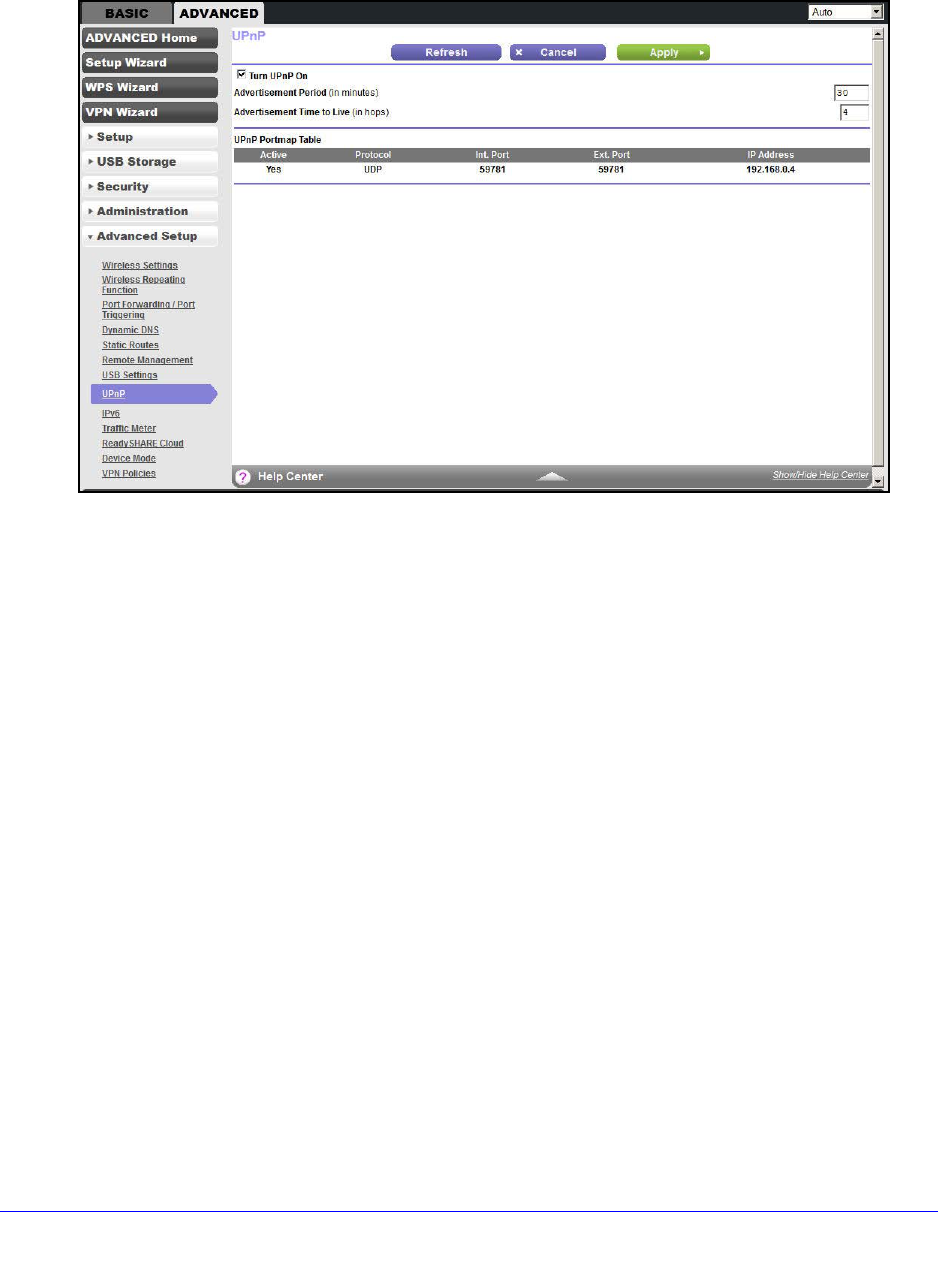
To turn on Universal Plug and Play:
1. Select ADVANCED > Advanced Setup > UPnP. The UPnP screen displays.
2. The available settings and information in this screen are:
Turn UPnP On. UPnP can be enabled or disabled for automatic device configuration.
The default setting for UPnP is disabled. If this check box is not selected, the WiFi
modem router does not allow any device to automatically control the resources, such as
port forwarding (mapping) of the WiFi modem router.
Advertisement Period. The advertisement period is how often the WiFi modem router
broadcasts its UPnP information. This value can range from 1 to 1440 minutes. The
default period is 30 minutes. Shorter durations ensure that control points have current
device status at the expense of more network traffic. Longer durations can compromise
the freshness of the device status, but can significantly reduce network traffic.
Advertisement Time to Live. The time to live for the advertisement is measured in hops
(steps) for each UPnP packet sent. The time to live hop count is the number of steps a
broadcast packet is allowed to propagate for each UPnP advertisement before it
disappears. The number of hops can range from 1 to 255. The default value for the
advertisement time to live is 4 hops, which should be fine for most home networks. If you
notice that some devices are not being updated or reached correctly, it might be
necessary to increase this value.
UPnP Portmap Table. The UPnP Portmap Table displays the IP address of each UPnP
device that is accessing the WiFi modem router and which ports (internal and external)
that device has opened. The UPnP Portmap Table also displays what type of port is open
and whether that port is still active for each IP address.
3. Click Apply to save your settings.
Advanced Settings
119
D6200 WiFi Modem Router
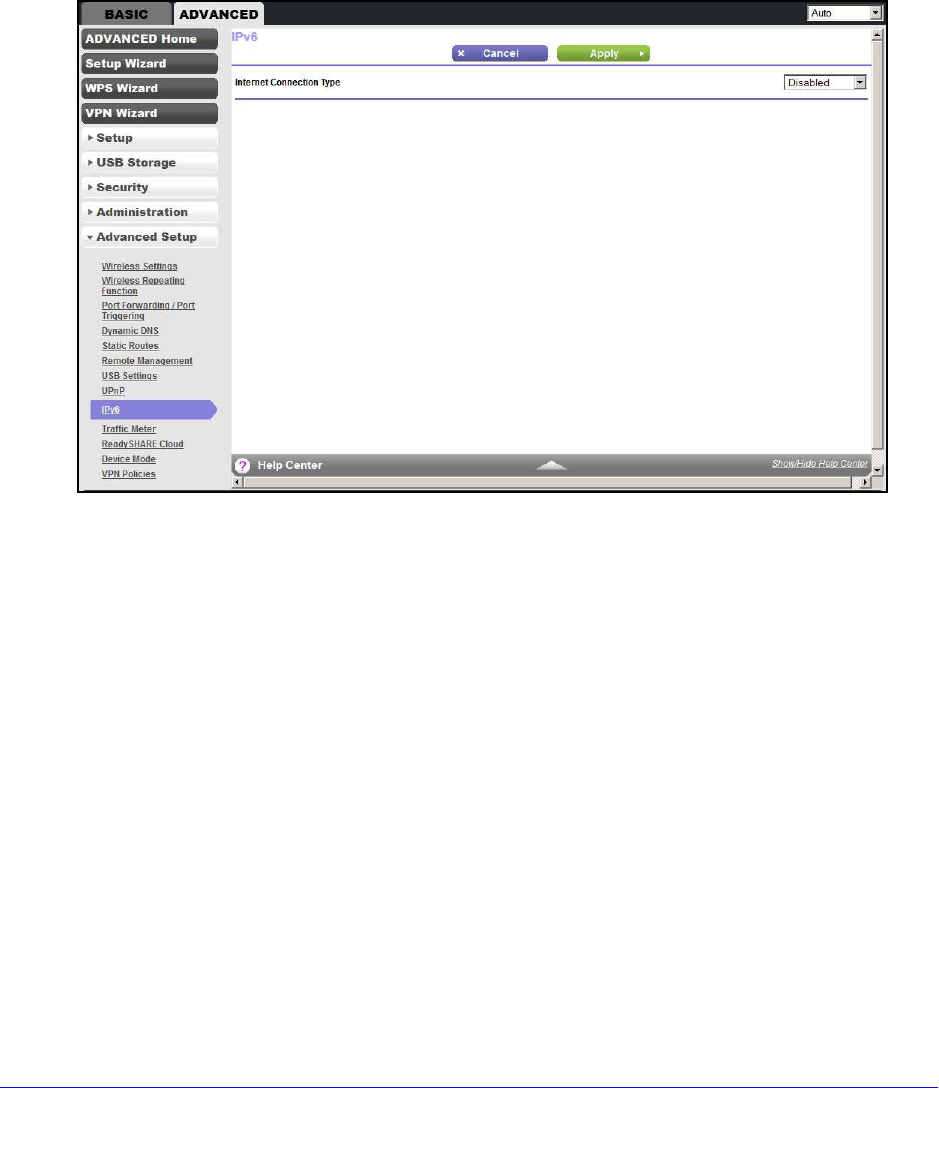
IPv6
You can use this feature to set up an IPv6 Internet connection type if NETGEAR genie does
not detect it automatically.
To set up an IPv6 Internet connection type:
1. Select ADVANCED > Advanced Setup > IPv6 to display the following screen:
2. Select the IPv6 connection type from the list. Your Internet service provider (ISP) can
provide this information.
•If your ISP did not provide details, you can select IPv6 Tunnel.
•If you are not sure, select Auto Detect so that the WiFi modem router detects the
IPv6 type that is in use.
•If your Internet connection does not use PPPoE, DHCP, or fixed, but is IPv6, then
select IPv6 auto config.
3. Click Apply so that your changes take effect.
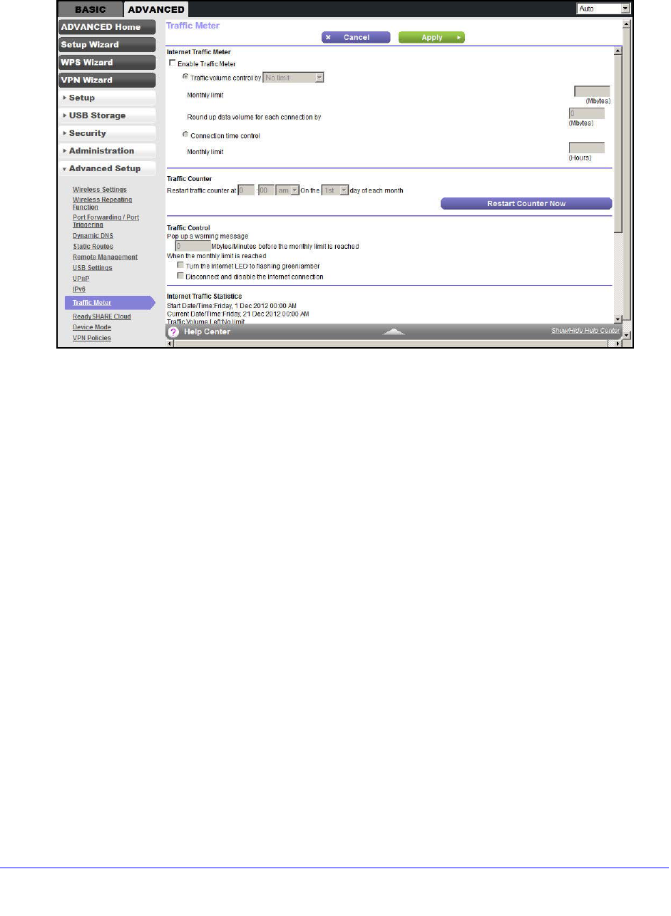
Traffic Meter
Traffic metering allows you to monitor the volume of Internet traffic passing through your WiFi
modem router’s Internet port. With the traffic meter utility, you can set limits for traffic volume,
set a monthly limit, and get a live update of traffic usage.
Advanced Settings
120
D6200 WiFi Modem Router
To monitor Internet traffic:
1. Click ADVANCED > Advanced Setup > Traffic Meter to display the following screen:
2. To enable the traffic meter, select the Enable Traffic Meter check box.
3. If you would like to record and restrict the volume of Internet traffic, select the Traffic
volume control by radio button. You can select one of the following options for controlling
the traffic volume:
•No Limit. No restriction is applied when the traffic limit is reached.
•Download only. The restriction is applied to incoming traffic only.
•Both Directions. The restriction is applied to both incoming and outgoing traffic.
4. You can limit the amount of data traffic allowed per month by specifying how many Mbytes
per month are allowed or by specifying how many hours of traffic are allowed.
5. Set the traffic counter to begin at a specific time and date.
6. Set up traffic control to issue a warning message before the monthly limit of Mbytes or hours
is reached. You can select one of the following to occur when the limit is attained:
•The Internet LED blinks green or red.
•The Internet connection is disconnected and disabled.
7. Set up Internet traffic statistics to monitor the data traffic.
8. Click the Traffic Status button to get a current update of Internet traffic status on your WiFi
modem router.
9. Click Apply to save your settings.
Advanced Settings
121
D6200 WiFi Modem Router
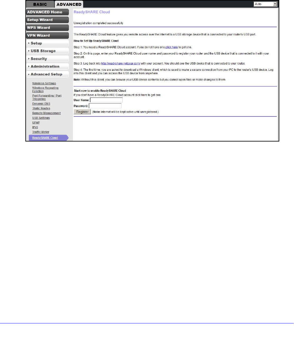
ReadySHARE Cloud
The ReadySHARE Cloud feature provides remote access over the Internet to a USB storage
device that is connected to your router’s USB port no matter where you are. You can also
invite family members or friends to access the USB storage device.
To set up ReadySHARE Cloud:
1. Click ADVANCED > Advanced Setup > ReadySHARE Cloud to display the following
screen:
2. You need a ReadySHARE Cloud account. If you do not have one, click the link provided in
this screen to go to NETGEAR ReadySHARE Cloud page to create an account.
Enter a valid email address that is used to recover your user name and password.
3. Return to this screen.
Note: This step has to be initiated from your NETGEAR router. You cannot
register your router through the NETGEAR ReadySHARE Cloud website at
http://readyshare.netgear.com.
a. Enter your ReadySHARE Cloud user name and password to register your router and
the USB device that is connected to it.
Fill in the User Name and Password fields. These entries are the ReadySHARE
Cloud account you created on NETGEAR website in Step 2.
b. Click Register.
•The router with the USB storage device displays in your ReadySHARE Cloud
account only after you register it. The Internet connection between the router and
the ReadySHARE Cloud server is kept alive until you unregister it.

Advanced Settings
122
D6200 WiFi Modem Router
•You can also register the router with another account after unregistering the router
from previous account.
4. Log in to http://readyshare.netgear.com with your account. You should see the USB device
that is connected to your router. By default, all contents of the USB device are accessible.
You can create a share that is limited to any subset of the contents with the security level
you specify.
5. The first time you use ReadySHARE Cloud, you are asked to download a Windows client
that makes a secure connection from your computer to the router’s USB device. Log in to
this client to access the USB device from anywhere.
Note: Currently, you can download only the Windows OS client. The Mac OS
client will be ready at a later time on the website.
Note: Without this client, you can only browse your USB device contents by
clicking the + icon (Add Share) on the website. You are not able to open files
nor can you change them.
Advanced Settings
123
D6200 WiFi Modem Router
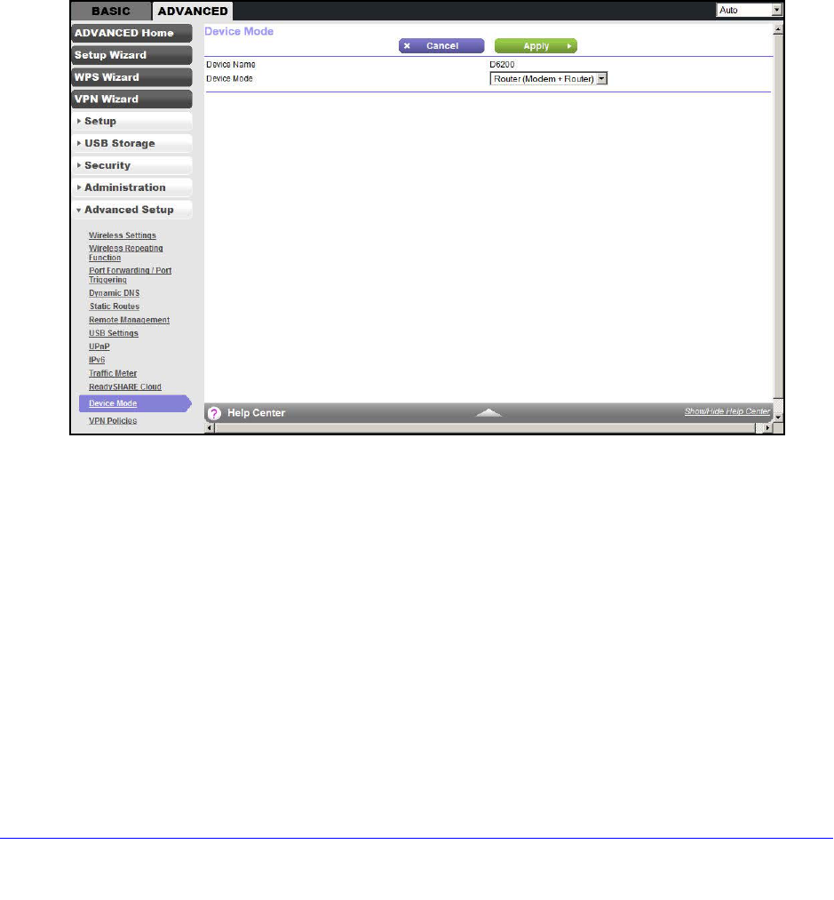
Device Mode
When the WiFi modem router is in Router mode, this screen allows switching to Modem
mode, where the WiFi modem router acts as a pure bridge or DSL modem.
Routing, firewall, wireless support, USB, and the traffic meter are not available in Modem
mode. A typical application is a small-to-medium business scenario where the WiFi modem
router is used for DSL connectivity behind a carrier class router or firewall or security device
manager. When the WiFi modem router is in Modem mode, this screen allows switching back
to Router mode with all of the standard features.
To switch the device mode:
1. Click ADVANCED > Advanced Setup > Device Mode to display the following screen:
2. From the Device Mode list, select Router (Modem + Router) or Modem (Modem only).
3. Click Apply to save your settings.
VPN Policies
Manage your VPN policies from the VPN Policies screen.
•Traffic covered by a policy is automatically sent through a VPN tunnel.
•Where traffic is covered by two or more policies, the first matching policy is used. In this
situation, the order of the policies is important. However, if you only have one policy for
each remote VPN endpoint, the policy order is not important.
•The VPN tunnel is created according to the parameters in the SA (security association).
•The remote VPN endpoint must have a matching SA, or else it refuses the connection.
Advanced Settings
124
D6200 WiFi Modem Router
Two types of VPN policies are possible:
•Manual. All settings (including the keys) for the VPN tunnel are input manually at each
end (both VPN endpoints). No third-party server or organization is involved.
•Auto. Some parameters for the VPN tunnel are generated automatically. This process
requires using the IKE (Internet Key Exchange) protocol to perform negotiations between
the two VPN endpoints.
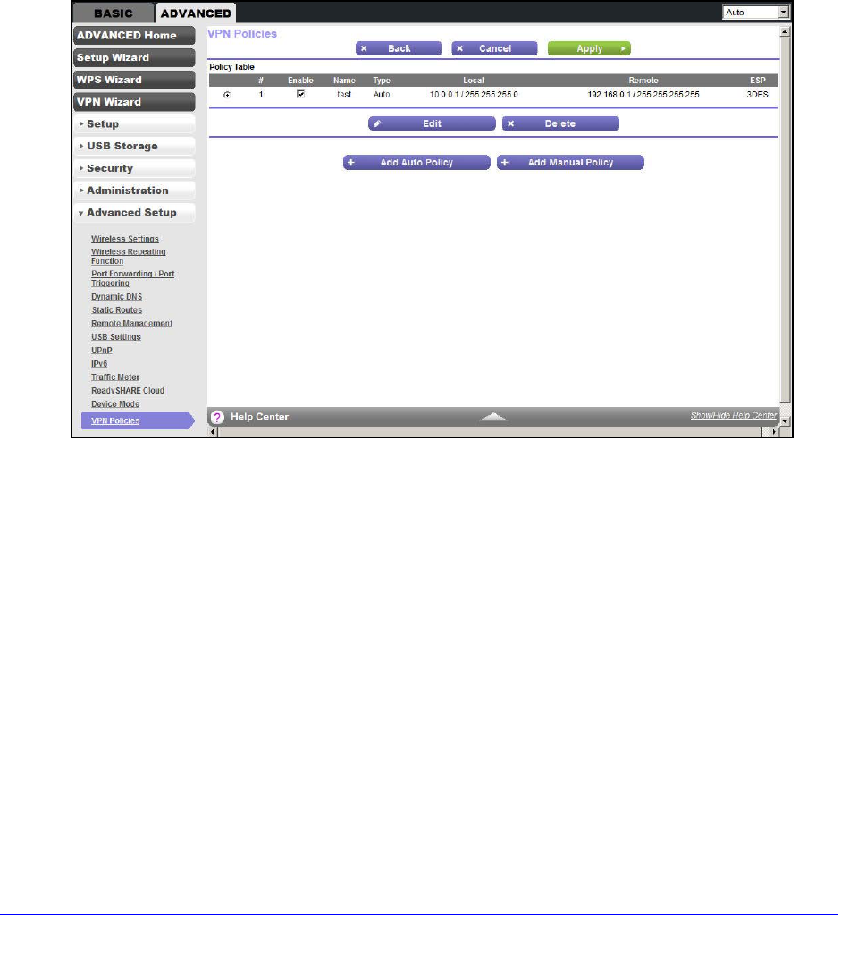
To manage the VPN policies:
1. Click ADVANCED > Advanced Setup > VPN Policies to display the following screen:
The Policy Table contains the following data:
•Enable. Use this check box to enable or disable a policy as required. Click Apply
when you are finished.
•Name. Each policy has a unique name to identify it.
•Type. The type is Auto or Manual.
•Local. IP address or address range on your local LAN. Traffic must be from (or to) the
addresses covered by this policy.
•Remote. IP address or address range of the remote network. Traffic must be to (or
from) the addresses covered by this policy.
•ESP. Encapsulating Security Payload. This setting specifies the encryption protocol
used for the VPN data.
2. Click the appropriate button to manage a VPN policy:
•Edit. Edit (modify) the selected policy. (Select a policy by selecting the radio button.)
•Delete. Delete the selected policy.
•Apply. Save any changes to the Enable setting for each policy.
Advanced Settings
125
D6200 WiFi Modem Router
•Cancel. Discard any unsaved changes to the Enable setting for each policy.
•Add Auto Policy. Change to the input screen for an Auto policy. When the new policy
is saved, it appears in the bottom row of the Policy Table. See Add or Edit an Auto
VPN Policy on page 125.
•Add Manual Policy. Change to the input screen for a Manual policy. When the new
policy is saved, it appears in the bottom row of the Policy Table. See Add or Edit a
Manual VPN Policy on page 128.
Add or Edit an Auto VPN Policy
An Auto VPN policy uses the IKE (Internet Key Protocol) to exchange and negotiate
parameters for the IPsec SA (security association). Because of this negotiation, not all of the
settings on this VPN gateway have to match the settings on the remote VPN endpoint.
Where settings have match, this requirement is indicated.
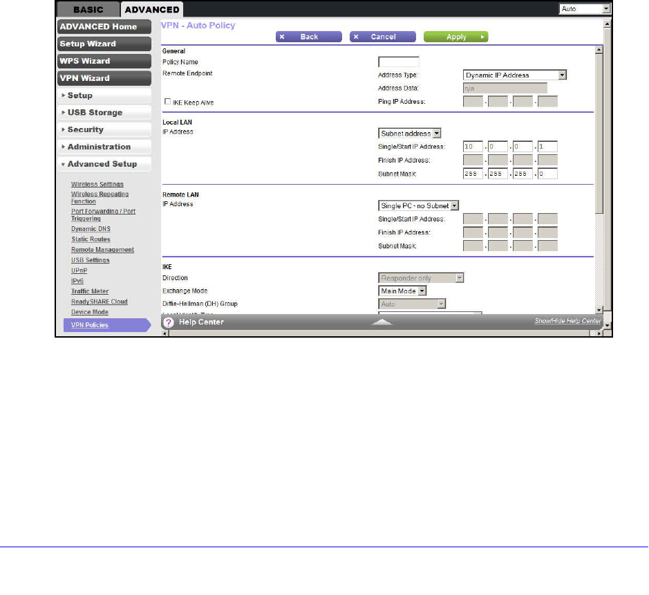
To add or edit an Auto VPN Policy:
1. Click ADVANCED > Advanced Setup > VPN Policies, and click the Add Auto Policy
button to display the following screen:
2. Enter or select the following parameters:
•General. These settings identify this policy and determine its major characteristics.
- Policy Name. Enter a unique name to identify this policy. This name is not
supplied to the remote VPN endpoint. It is used only to help you manage the
policies.
- Remote VPN Endpoint. If the remote endpoint has a dynamic IP address, select
Dynamic IP Address. No address data input is required.

Advanced Settings
126
D6200 WiFi Modem Router
Otherwise, select the desired option (IP address or domain name) and enter the
address of the remote VPN endpoint you wish to connect to.
The remote VPN endpoint must have this VPN gateway’s address entered as its
remote VPN endpoint.
- IKE Keep Alive. Check this check box if you wish to ensure that a connection is
kept open, or, if that is not possible, it is quickly reestablished when disconnected.
The ping IP address has to be associated with the remote endpoint. Either the
WAN or a LAN address can be used; a LAN address is preferable. This IP
address is pinged to generate some traffic for the VPN tunnel.
•Local LAN. These settings identify which computers on your LAN are covered by this
policy. For each selection, data must be provided as follows:
- Single address. Enter an IP address in the Single/Start IP address field. Typically,
this setting is used when you wish to make a single server on your LAN available
to remote users.
- Range address. Enter the starting IP address in the Single/Start IP address field,
and the finish IP address in the Finish IP address field. A range must be an
address range used on your LAN.
- Subnet address. Enter an IP address in the Single/Start IP address field, and the
desired network mask in the Subnet Mask field.
The remote VPN endpoint must have these IP addresses entered as its remote
addresses.
•Remote LAN. These settings identify which computers on the remote LAN are
covered by this policy. For each selection, data must be provided as follows:
- Single PC - no Subnet. Select this option if there is no LAN (only a single
computer) at the remote endpoint. If this option is selected, no additional data is
required.
- Single address. Enter an IP address in the Single/Start IP address field. This
value must be an address on the remote LAN. Typically, this setting is used when
you wish to access a server on the remote LAN.
- Range address. Enter the starting IP address in the Single/Start IP address field,
and the finish IP address in the Finish IP address field. This range must be an
address range used on the remote LAN.
- Subnet address. Enter an IP address in the Single/Start IP address field, and the
desired network mask in the Subnet Mask field.
The remote VPN endpoint must have these IP addresses entered as its local
addresses.
•IKE.
- Direction/Type. This setting is used when determining if the IKE policy matches
the current traffic. Select the desired option.
- Responder only. Incoming connections are allowed, but outgoing connections
are blocked.

Advanced Settings
127
D6200 WiFi Modem Router
- Initiator and Responder. Both incoming and outgoing connections are allowed.
- Exchange Mode. Currently, only Main Mode is supported. Ensure that the remote
VPN endpoint is set to use Main Mode.
- Diffie-Hellman (DH) Group. The Diffie-Hellman algorithm is used when the
connection exchanges keys. The DH Group setting determines the bit size used
in the exchange. This value must match the value used on the remote VPN
gateway.
- Local Identity Type. Select the desired option to match the Remote Identity Type
setting on the remote VPN endpoint.
- WAN IP Address. Your Internet IP address.
- Fully Qualified Domain Name. Your domain name.
- Fully Qualified User Name. Your name, email address, or other ID.
- Local Identity Data. Enter the data for the selection. When WAN IP Address is
selected, no input is required.
- Remote Identity Type. Select the desired option to match the Local Identity Type
setting on the remote VPN endpoint.
- IP Address. The Internet IP address of the remote VPN endpoint.
- Fully Qualified Domain Name. The domain name of the remote VPN endpoint.
- Fully Qualified User Name. The name, email address, or other ID of the remote
VPN endpoint.
- Remote Identity Data. Enter the data for the selection. When IP Address is
selected, no input is required.
•Parameters.
- Encryption Algorithm. The encryption algorithm used for both IKE and IPSec.
This setting must match the setting used on the remote VPN gateway.
- Authentication Algorithm. The authentication algorithm used for both IKE and
IPSec. This setting must match the setting used on the remote VPN gateway.
- Pre-shared Key. The key has to be entered both here and on the remote VPN
gateway.
- SA Life Time. This setting determines the time interval before the SA (security
association) expires. (It is automatically reestablished as required.) While using a
short time period (or data amount) increases security, it also degrades
performance. It is common to use periods over an hour (3600 seconds) for the SA
lifetime. This setting applies to both IKE and IPSec SAs.
- Enable PFS (Perfect Forward Secrecy). If enabled, security is enhanced by
ensuring that the key is changed at regular intervals. Also, even if one key is
broken, subsequent keys are no easier to break. (Each key has no relationship to
the previous key.)
This setting applies to both IKE and IPSec SAs. When configuring the remote
endpoint to match this setting, you might need to specify the key group used. For
this device, the key group is the same as the DH Group setting in the IKE section.
3. Click Apply when done.
Advanced Settings
128
D6200 WiFi Modem Router
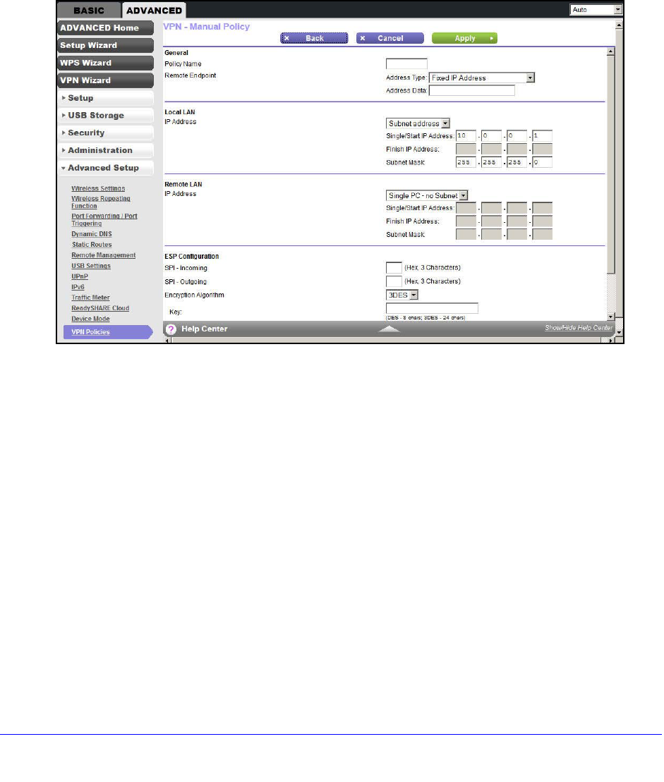
Add or Edit a Manual VPN Policy
A Manual VPN policy requires all settings (including the keys) for the VPN tunnel to be
manually input at each end (both VPN endpoints). No third-party server or organization is
involved.
To add or edit a Manual VPN policy:
1. Click ADVANCED > Advanced Setup > VPN Policies, and click the Add Manual
Policy button to display the following screen:
2. Enter or select the following parameters:
•General. These settings identify this policy and determine its major characteristics.
- Policy Name. Enter a unique name to identify this policy. This name is not
supplied to the remote VPN endpoint. It is used only to help you manage the
policies.
- Remote VPN Endpoint. Select the desired option (IP address or domain name)
and enter the address or domain name of the remote VPN endpoint you wish to
connect to.
The remote VPN endpoint must have this VPN gateway’s address entered as its
remote VPN endpoint.
•Local LAN. These settings identify which computers on your LAN are covered by this
policy. For each selection, data must be provided as follows:
- Single address. Enter an IP address in the Single/Start IP address field. Typically,
this setting is used when you wish to make a single server on your LAN available
to remote users.

Advanced Settings
129
D6200 WiFi Modem Router
- Range address. Enter the starting IP address in the Single/Start IP address field,
and the finish IP address in the Finish IP address field. This setting must be an
address range used on your LAN.
- Subnet address. Enter an IP address in the Single/Start IP address field, and the
desired network mask in the Subnet Mask field.
The remote VPN endpoint must have these IP addresses entered as its remote
addresses.
•Remote LAN. These identify which computers on the remote LAN are covered by this
policy. For each selection, data must be provided as follows:
- Single PC - dynamic IP. Select this option if there is no LAN (only a single
computer) at the remote endpoint. If this option is selected, no additional data is
required.
- Single address. Enter an IP address in the Single/Start IP address field. This
setting must be an address on the remote LAN. Typically, this setting is used
when you wish to access a server on the remote LAN.
- Range address. Enter the starting IP address in the Single/Start IP address field,
and the finish IP address in the Finish IP address field. This range must be an
address range used on the remote LAN.
- Subnet address. Enter an IP address in the Single/Start IP address field, and the
desired network mask in the Subnet Mask field.
The remote VPN endpoint must have these IP addresses entered as its local
addresses.
•ESP Configuration. ESP (encapsulating security payload) provides security for the
payload (data) sent through the VPN tunnel.
- SPI. Enter the required SPIs. Each policy must have unique SPIs. These settings
must match the remote VPN endpoint. The Incoming setting here must match the
Outgoing setting on the remote VPN endpoint, and the Outgoing setting here
must match the Incoming setting on the remote VPN endpoint.
- Encryption. Select the desired encryption algorithm, and enter the key in the field
provided. For 3DES, the keys should be 24 ASCII characters (48 hex characters).
- Authentication. Select the desired authentication algorithm, and enter the key in
the field provided. For MD5, the keys should be 16 ASCII characters (32 hex
characters). For SHA-1, the keys should be 20 ASCII (40 hex characters).
3. Click Apply when done.

130
10
10. Troubleshooting
Diagnose and solve problems
This chapter provides information to help you diagnose and solve problems you might have with
your WiFi modem router. If you do not find the solution here, check the NETGEAR support site at
http://support.netgear.com/general/contact/default.aspx for product and contact information.
This chapter contains the following sections:
•Quick Tips
•Troubleshoot with the LEDs
•Cannot Log In to the Router
•Cannot Access the Internet
•Changes Not Saved
•Incorrect Date or Time
•Wireless Connectivity
•Restore the Factory Settings and Password
•Troubleshoot Your Network Using the Ping Utility

Troubleshooting
131
D6200 WiFi Modem Router
Quick Tips
This section describes tips for troubleshooting some common problems.
Sequence to Restart Your Network
Be sure to restart your network in this sequence:
1. Turn off and unplug the modem.
2. Turn off the WiFi modem router and computers.
3. Plug in the modem and turn it on. Wait 2 minutes.
4. Turn on the WiFi modem router and wait 2 minutes.
5. Turn on the computers.
Check Ethernet Cable Connections
Make sure that the Ethernet cables are securely plugged in:
•The Internet status LED on the WiFi modem router is lit if the Ethernet cable connecting
the WiFi modem router and the modem is plugged in securely and the modem and WiFi
modem router are turned on.
•For each powered-on computer connected to the WiFi modem router by an Ethernet
cable, the corresponding numbered router LAN port LED is lit.
Wireless Settings
Make sure that the wireless settings in the computer and WiFi modem router match exactly.
•For a wirelessly connected computer, the wireless network name (SSID) and wireless
security settings of the WiFi modem router and wireless computer need to match exactly.
•If you set up an access list in the Advanced Wireless Settings screen, you have to add
each wireless computer’s MAC address to the WiFi modem router’s access list.
Network Settings
Make sure that the network settings of the computer are correct:
•Wired and wirelessly connected computers need to have network (IP) addresses on the
same network as the WiFi modem router. The simplest way to achieve this address
commonality is to configure each computer to obtain an IP address automatically using
DHCP.
•Some cable modem service providers require you to use the MAC address of the
computer initially registered on the account. You can view the MAC address in the
Attached Devices screen.

Troubleshooting
132
D6200 WiFi Modem Router
Troubleshoot with the LEDs
After you turn on power to the WiFi modem router, the following sequence of events should
occur:
1. When power is first applied, verify that the Power LED is lit.
2. Verify that the Power LED turns red within a few seconds, indicating that the self-test is
running.
3. After approximately 30 seconds, verify the following:
•The Power LED is solid green.
•The Internet LED is lit.
•The Ethernet LED is lit for any local port that is connected to a computer. This LED
indicates that a link has been established to the connected device.
The LEDs on the front panel of the WiFi modem router can be used for troubleshooting.
Power LED Is Off or Blinking
•Make sure that the power cord is securely connected to your WiFi modem router and that
the power adapter is securely connected to a functioning power outlet.
•Make sure that you are using the power adapter that NETGEAR supplied for this product.
•If the Power LED blinks slowly and continuously, the WiFi modem router firmware is
corrupted. This situation can happen if a firmware upgrade is interrupted, or if the WiFi
modem router detects a problem with the firmware. If the error persists, you have a
hardware problem. For recovery instructions or help with a hardware problem, contact
technical support at http://support.netgear.com/general/contact/default.aspx.
Power LED Stays Red
When the WiFi modem router is turned on, the Power LED turns red for about 20 seconds
and then turns green. If the LED does not turn green, the WiFi modem router has a problem.
If the Power LED is still red one minute after you turn on power to the WiFi modem router:
1. Turn off the power and back on to see if the WiFi modem router recovers.
2. Press and hold the Restore Factory Settings button to return the WiFi modem router to
its factory settings. See Factory Settings on page 141.
If the error persists, you might have a hardware problem and should contact technical support
at www.netgear.com/support.
LEDs Never Turn Off
When the WiFi modem router is turned on, the LEDs turn on for about 10 seconds and then
turn off. If all the LEDs stay lit, a fault exists within the WiFi modem router.

Troubleshooting
133
D6200 WiFi Modem Router
If all LEDs are still lit 1 minute after power-up:
•Cycle the power to see if the WiFi modem router recovers.
•Press and hold the Restore Factory Settings button to return the WiFi modem router to
its factory settings. See Factory Settings on page 141.
If the error persists, you might have a hardware problem and should contact technical
support at www.netgear.com/support.
Internet or Ethernet Port LEDs Are Off
If the Internet LED or the Ethernet port LEDs do not light when the Ethernet connection is
made, check the following:
•Make sure that the Ethernet cable connections are secure at the WiFi modem router and
at the modem or computer.
•Make sure that power is turned on to the connected modem or computer.
•Be sure that you are using the correct cable.
When connecting the WiFi modem router’s Internet port to a cable or DSL modem, use
the cable that was supplied with the cable or DSL modem. This cable could be a standard
straight-through Ethernet cable or an Ethernet crossover cable.
Wireless LEDs Are Off
If the Wireless LEDs stay off, check to see if the Wireless On/Off button on the WiFi modem
router has been pressed. This button turns the wireless radios in the WiFi modem router on
and off. The Wireless LEDs are lit when the wireless radio is turned on.
The Push 'N' Connect (WPS) Button Blinks Green
If after you press the WPS button and the button blinks green, check the following:
•Make sure that you are using the button and not the WiFi modem router’s built-in
registrar.
•Check that PIN verification has succeeded for the wireless device you are adding to the
wireless network.
•Make sure that you have not pressed the WPS button on the top of the WiFi modem
router after disabling the WPS feature (you logged in to the WiFi modem router and
disabled this feature previously).
•Check that the WiFi modem router is not in the temporary AP setup locked state (if you
are using the wireless repeater function).

Troubleshooting
134
D6200 WiFi Modem Router
Cannot Log In to the Router
If you are unable to log in to the WiFi modem router from a computer on your local network,
check the following:
•If you are using an Ethernet-connected computer, check the Ethernet connection
between the computer and the WiFi modem router as described in the previous section.
•Make sure that your computer’s IP address is on the same subnet as the WiFi modem
router. If you are using the recommended addressing scheme, your computer’s address
should be in the range of 192.168.0.2 to 192.168.0.254.
•If your computer’s IP address is shown as 169.254.x.x, recent versions of Windows and
Mac OS generate and assign an IP address if the computer cannot reach a DHCP server.
These autogenerated addresses are in the range of 169.254.x.x. If your IP address is in
this range, check the connection from the computer to the WiFi modem router, and reboot
your computer.
•If your WiFi modem router’s IP address was changed and you do not know the current IP
address, clear the WiFi modem router’s configuration to factory defaults. This procedure
sets the WiFi modem router’s IP address to 192.168.0.1. This procedure is explained in
Factory Settings on page 141.
•Make sure that your browser has Java, JavaScript, or ActiveX enabled. If you are using
Internet Explorer, click Refresh to be sure that the Java applet is loaded.
•Try quitting the browser and launching it again.
•Make sure that you are using the correct login information. The factory default login name
is admin and the password is password. Make sure that Caps Lock is off when you enter
this information.
•If you are attempting to set up your NETGEAR WiFi modem router as an additional router
behind an existing router in your network, consider replacing the existing router instead.
NETGEAR does not support such a configuration.
•If you are attempting to set up your NETGEAR WiFi modem router as a replacement for
an ADSL gateway in your network, the WiFi modem router cannot perform many gateway
services, for example, converting ADSL or cable data into Ethernet networking
information. NETGEAR does not support such a configuration.
Cannot Access the Internet
If you can access your router but you are unable to access the Internet, first determine
whether the WiFi modem router can obtain an IP address from your Internet service provider
(ISP). Unless your ISP provides a fixed IP address, your WiFi modem router requests an IP
address from the ISP. You can determine whether the request was successful using the
Router Status screen.
To check the WAN IP address:
1. Start your browser and select an external site such as http://www.netgear.com.

Troubleshooting
135
D6200 WiFi Modem Router
2. Access the WiFi modem router interface at http://www.routerlogin.net.
3. Select Administration > Router Status.
4. Check that an IP address is shown for the Internet port. If 0.0.0.0 is shown, your WiFi
modem router has not obtained an IP address from your ISP.
If your WiFi modem router cannot obtain an IP address from the ISP, you might need to force
your cable or DSL modem to recognize your new WiFi modem router by restarting your
network, as described in Sequence to Restart Your Network on page 131.
If your WiFi modem router is still unable to obtain an IP address from the ISP, the problem
might be one of the following:
•Your Internet service provider (ISP) might require a login program.
Ask your ISP whether it requires PPP over Ethernet (PPPoE) or some other type of login.
•If your ISP requires a login, the login name and password might be set incorrectly.
•Your ISP might check for your computer’s host name.
Assign the computer host name of your ISP account as the account name in the Internet
Basic Settings screen.
•Your ISP allows only one Ethernet MAC address to connect to the Internet and might
check for your computer’s MAC address. In this case, do one of the following:
-Inform your ISP that you have bought a new network device, and ask them to use the
WiFi modem router’s MAC address.
-Configure your WiFi modem router to clone your computer’s MAC address.
If your WiFi modem router can obtain an IP address, but your computer is unable to load any
web pages from the Internet:
•Your computer might not recognize any DNS server addresses.
A DNS server is a host on the Internet that translates Internet names (such as www
addresses) to numeric IP addresses. Typically, your ISP provides the addresses of one or
two DNS servers for your use. If you entered a DNS address during the WiFi modem
router’s configuration, reboot your computer, and verify the DNS that address. You can
configure your computer manually with DNS addresses, as explained in your operating
system documentation.
•Your computer might not have the WiFi modem router configured as its TCP/IP gateway.
If your computer obtains its information from the WiFi modem router by DHCP, reboot the
computer, and verify the gateway address.
•You might be running login software that is no longer needed.
If your ISP provided a program to log you in to the Internet (such as WinPoET), you no
longer need to run that software after installing your WiFi modem router. You might need
to go to Internet Explorer and select Tools > Internet Options, click the Connections
tab, and select Never dial a connection.

Troubleshooting
136
D6200 WiFi Modem Router
Troubleshoot PPPoE
If you are using PPPoE, try troubleshooting your Internet connection.
To troubleshoot a PPPoE connection:
1. Log in to the WiFi modem router.
2. Select Administration > Router Status.
3. Click Connection Status. If all of the steps indicate OK, your PPPoE connection is
working.
If any of the steps indicate Failed, you can attempt to reconnect by clicking Connect. The
WiFi modem router continues to attempt to connect indefinitely.
If you cannot connect after several minutes, you might be using an incorrect service name,
user name, or password. There might also be a provisioning problem with your ISP.
Note: Unless you connect manually, the WiFi modem router does not
authenticate using PPPoE until data is transmitted to the network.
Troubleshoot Internet Browsing
If your WiFi modem router can obtain an IP address but your computer is unable to load any
web pages from the Internet, check the following:
•Your computer might not recognize any DNS server addresses. A DNS server is a host
on the Internet that translates Internet names (such as www addresses) to numeric IP
addresses.
Typically, your ISP provides the addresses of one or two DNS servers for your use. If you
entered a DNS address during the WiFi modem router’s configuration, restart your
computer.
Alternatively, you can configure your computer manually with a DNS address, as
explained in the documentation for your computer.
•Your computer might not have the WiFi modem router configured as its default gateway.
Reboot the computer, and verify that the WiFi modem router address
(www.routerlogin.net) is listed by your computer as the default gateway address.
•You might be running login software that is no longer needed. If your ISP provided a
program to log you in to the Internet (such as WinPoET), you no longer need to run that
software after installing your WiFi modem router. You might need to go to Internet
Explorer and select Tools > Internet Options, click the Connections tab, and select
Never dial a connection.
If the WiFi modem router does not save changes you have made in the browser interface,
check the following:

Troubleshooting
137
D6200 WiFi Modem Router
•When entering configuration settings, be sure to click Apply before moving to another
screen or tab, or your changes could be lost.
•Click Refresh or Reload in the web browser. The changes might have occurred, but the
web browser might be caching the old configuration.
Changes Not Saved
If the WiFi modem router does not save the changes you make in the WiFi modem router
interface, check the following:
•When entering configuration settings, always click the Apply button before moving to
another screen or tab, or your changes are lost.
•Click the Refresh or Reload button in the web browser. The changes might have
occurred, but the old settings might be in the web browser’s cache.
Incorrect Date or Time
Select ADVANCED > Security > Schedule to display the current date and time. The WiFi
modem router uses the Network Time Protocol (NTP) to obtain the current time from one of
several network time servers on the Internet. Each entry in the log is stamped with the date
and time of day. Problems with the date and time function can include the following:
•Date shown is January 1, 2000. This value means the WiFi modem router has not yet
successfully reached a network time server. Check that your Internet access is
configured correctly. If you have finished setting up the WiFi modem router, wait at least 5
minutes, and check the date and time again.
•Time is off by one hour. The WiFi modem router does not automatically sense daylight
saving time. In the Schedule screen, select the Automatically adjust for daylight
savings time check box.
Wireless Connectivity
If you are having trouble connecting wirelessly to the WiFi modem router, try to isolate the
problem.
•Does the wireless device or computer that you are using find your wireless network?
If not, check the Wireless LEDs on the front of the WiFi modem router. They should be lit.
If they are not, you can press the WiFi On/Off button on the back of the WiFi modem
router to turn the WiFi modem router’s wireless radio back on.
If you disabled the WiFi modem router’s SSID broadcast, then your wireless network is
hidden and does not show up in your wireless client’s scanning list. By default, SSID
broadcast is enabled.
•Does your wireless device support the security that you are using for your wireless
network (WPA or WPA2)?

Troubleshooting
138
D6200 WiFi Modem Router
•If you want to view the wireless settings for the WiFi modem router, use an Ethernet cable
to connect a computer to a LAN port on the WiFi modem router. Then log in to the WiFi
modem router and select Setup > Wireless Settings see (Basic Wireless Settings on
page 35).
Note: Be sure to click Apply when you make changes.
Wireless Signal Strength
If your wireless device finds your network, but the signal strength is weak, check these
conditions:
•Is your WiFi modem router too far from your computer, or too close? Place your computer
near the WiFi modem router, but at least 6 feet away, and see whether the signal strength
improves.
•Is your wireless signal blocked by objects between the WiFi modem router and your
computer?
Restore the Factory Settings and Password
This section explains how to restore the factory settings, changing the WiFi modem router’s
administration password back to password. You can erase the current configuration and
restore factory defaults in two ways:
•Use the Erase function of the WiFi modem router (see Erase on page 93).
•Use the Restore Factory Settings button on the back of the WiFi modem router. See
Factory Settings on page 141. If you restore the factory settings and the WiFi modem
router fails to restart, or the green Power LED continues to blink, the unit might be
defective. If the error persists, you might have a hardware problem and should contact
technical support at http://www.netgear.com/support.
Troubleshoot Your Network Using the Ping Utility
Most network devices and routers contain a ping utility that sends an echo request packet to
the designated device. The device then responds with an echo reply. You can easily
troubleshoot a network by using the ping utility in your computer or workstation.
Test the LAN Path to Your Router
You can ping the WiFi modem router from your computer to verify that the LAN path to your
WiFi modem router is set up correctly.

Troubleshooting
139
D6200 WiFi Modem Router
To ping the WiFi modem router from a computer running Windows:
1. From the Windows toolbar, click Start and select Run.
2. In the field provided, type ping followed by the IP address of the WiFi modem router, as in
this example:
ping www.routerlogin.net
3. Click OK.
You should see a message like this one:
Pinging <IP address > with 32 bytes of data
If the path is working, you see this message:
Reply from < IP address >: bytes=32 time=NN ms TTL=xxx
If the path is not working, you see this message:
Request timed out
If the path is not functioning correctly, you might have one of the following problems:
•Wrong physical connections
For a wired connection, make sure that the numbered LAN port LED is lit for the port to
which you are connected.
Check that the appropriate LEDs are lit for your network devices. If your WiFi modem
router and computer are connected to a separate Ethernet switch, make sure that the
Ethernet LEDs are lit for the switch ports that are connected to your computer and WiFi
modem router.
•Wrong network configuration
Verify that the Ethernet card driver software and TCP/IP software are both installed and
configured on your computer.
Verify that the IP address for your WiFi modem router and your computer are correct and
that the addresses are on the same subnet.
Test the Path from Your Computer to a Remote Device
After verifying that the LAN path works correctly, test the path from your computer to a remote
device.
1. From the Windows toolbar, click Start and select Run.
2. In the Windows Run window, type:
ping -n 10 <IP address>
where <IP address> is the IP address of a remote device such as your ISP DNS server.
If the path is functioning correctly, replies like the examples shown in the previous section are
displayed.

Troubleshooting
140
D6200 WiFi Modem Router
If you do not receive replies:
•Check that your computer has the IP address of your WiFi modem router listed as the
default gateway. If the IP configuration of your computer is assigned by DHCP, this
information is not visible in your computer’s Network Control Panel. Verify that the IP
address of the WiFi modem router is listed as the default gateway.
•Check to see that the network address of your computer (the portion of the IP address
specified by the subnet mask) is different from the network address of the remote device.
•Check that your cable or DSL modem is connected and functioning.
•If your ISP assigned a host name to your computer, enter that host name as the account
name in the Internet Basic Settings screen.
•Your ISP could be rejecting the Ethernet MAC addresses of all but one of your computers.
Many broadband ISPs restrict access by allowing traffic only from the MAC address of your
broadband modem, but some ISPs additionally restrict access to the MAC address of a
single computer connected to that modem. If so, configure your WiFi modem router to “clone”
or “spoof” the MAC address from the authorized computer.
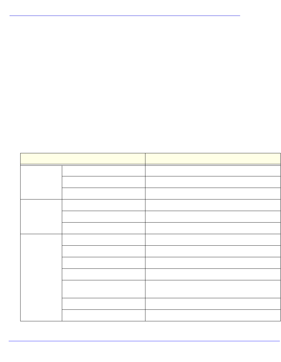
141
A
A. Supplemental Information
Factory settings and technical specifications
This appendix provides factory default settings and technical specifications for the D6200 WiFi
Modem Router.
Factory Settings
You can return the WiFi modem router to its factory settings. Use the end of a paper clip or
some other similar object to press and hold the Restore Factory Settings button on the
back of the router for at least 5 seconds. The WiFi modem router resets and returns to the
factory settings. Your device returns to the factory configuration settings shown in the
following table.
Table 10. Factory default settings
Feature Default Behavior
Router login User login URL www.routerlogin.com or www.routerlogin.net
User name (case-sensitive) admin
Login password (case-sensitive) password
Internet
connection
WAN MAC address Use default hardware address
WAN MTU size 1500
Port speed Autosensing
Local network
(LAN)
LAN IP 192.168.0.1
Subnet mask 255.255.255.0
DHCP server Enabled
DHCP range 192.168.0.2 to 192.168.0.254
Allow a registrar to configure this
router
Enabled
DHCP starting IP address 192.168.0.2
DHCP ending IP address 192.168.0.254

Supplemental Information
142
D6200 WiFi Modem Router
Local network
(LAN) continued
DMZ Disabled
Time zone GMT for WW except NA and GR, GMT+1 for GR, GMT-8
for NA
Time zone adjusted for daylight
savings time
Disabled
Firewall Inbound (communications coming
in from the Internet)
Disabled (except traffic on port 80, the HTTP port)
Outbound (communications going
out to the Internet)
Enabled (all)
Source MAC filtering Disabled
Wireless Wireless communication Enabled
SSID name See router label
Security Enabled
Broadcast SSID Enabled
Transmission speed Auto1
Country/region United States in the US, otherwise varies by region
RF channel 6 until region selected
Operating mode Up to 145 Mbps
Data rate Best
Output power Full
Firewall Inbound (communications coming
in from the Internet)
Disabled (bars all unsolicited requests)
Outbound (communications going
out to the Internet)
Enabled (all)
1. Maximum Wireless signal rate derived from IEEE Standard 802.11 specifications. Actual throughput varies.
Network conditions and environmental factors, including volume of network traffic, building materials and
construction, and network overhead lower actual data throughput rate.
Table 10. Factory default settings (continued)
Feature Default Behavior

Supplemental Information
143
D6200 WiFi Modem Router
Technical Specifications
Table 11. D6200 Router specifications
Feature Description
Data and routing protocols TCP/IP, RIP-1, RIP-2, DHCP, PPPoE, Dynamic DNS, UPnP, and SMB
Power adapter • North America: 120V, 60 Hz, input
• UK, Australia: 240V, 50 Hz, input
• Europe: 230V, 50 Hz, input
• All regions (output): 12V DC @ 5A, output
Dimensions 205 mm x 255 mm x 77 mm (8.07 in. x 10.04 in. x 3.03 in.)
Weight 654g (1.44 lbs)
Operating temperature 0° to 40°C (32º to 104ºF)
Operating humidity 90% maximum relative humidity, noncondensing
Electromagnetic emissions FCC Part 15 Class B
EN 55 022 (CISPR 22), Class B C-Tick N10947
LAN 10BASE-T or 100BASE-Tx, RJ-45
WAN 10BASE-T or 100BASE-Tx, RJ-45
Wireless Maximum wireless signal rate complies with the IEEE 802.11 standard. See the
footnote for the previous table.
Radio data rates Auto Rate Sensing
Data encoding standards IEEE 802.11n version 2.0
IEEE 802.11n, IEEE 802.11g, IEEE 802.11b 2.4 GHz
IEEE 802.11n, IEEE 802.11a 5.0 GHz
Maximum computers per
wireless network
Limited by the amount of wireless network traffic generated by each node
(typically 50–70 nodes).
Operating frequency range 2.4 GHz
2.412–2.462 GHz (US)
2.412–2.472 GHz (Japan)
2.412–2.472 GHz (Europe ETSI)
5 GHz
5.18–5.24 + 5.745–5.825 GHz (US)
5.18–5.24 GHz (Europe ETSI)
802.11 security WPA-PSK, WPA2-PSK, and WPA/WPA2 Enterprise.

144
B
B. Notification of Compliance
NETGEAR Dual Band - Wireless
Regulatory Compliance Information
This section includes user requirements for operating this product in accordance with National laws for usage of radio
spectrum and operation of radio devices. Failure of the end-user to comply with the applicable requirements may
result in unlawful operation and adverse action against the end-user by the applicable National regulatory authority.
This product's firmware limits operation to only the channels allowed in a particular Region or Country. Therefore, all
options described in this user's guide may not be available in your version of the product.
Europe – EU Declaration of Conformity
Products bearing the marking comply with the following EU directives:
• EMC Directive 2004/108/EC
• Low Voltage Directive 2006/95/EC
If this product has telecommunications functionality, it also complies with the requirements of the following EU
Directive:
• R&TTE Directive 1999/5/EC
Compliance with these directives implies conformity to harmonized European standards that are noted in the EU
Declaration of Conformity.
This device may not be used for setting up outdoor radio links in France and in some areas the RF output power may
be limited to 10 mW EIRP in the frequency range of 2454 - 2483.5 MHz. For detailed information the end-user should
contact the national spectrum authority in France.
FCC Requirements for Operation in the United States
FCC Information to User
This product does not contain any user serviceable components and is to be used with approved antennas only.
Any product changes or modifications will invalidate all applicable regulatory certifications and approvals.
FCC Guidelines for Human Exposure
This equipment complies with FCC radiation exposure limits set forth for an uncontrolled environment. This
equipment should be installed and operated with minimum distance of 20 cm between the radiator and your body.
FCC Declaration of Conformity
We, NETGEAR, Inc., 350 East Plumeria Drive, San Jose, CA 95134, declare under our sole responsibility that the
D6200 WiFi Modem Router complies with Part 15 Subpart B of FCC CFR47 Rules.
FCC Radio Frequency Interference Warnings & Instructions
This equipment has been tested and found to comply with the limits for a Class B digital device, pursuant to Part 15
of the FCC Rules. These limits are designed to provide reasonable protection against harmful interference in a
residential installation. This equipment uses and can radiate radio frequency energy and, if not installed and used in
accordance with the instructions, may cause harmful interference to radio communications. However, there is no
guarantee that interference will not occur in a particular installation. If this equipment does cause harmful

Notification of Compliance
145
D6200 WiFi Modem Router
interference to radio or television reception, which can be determined by turning the equipment off and on, the user
is encouraged to try to correct the interference by one or more of the following methods:
• Reorient or relocate the receiving antenna.
• Increase the separation between the equipment and the receiver.
• Connect the equipment into an electrical outlet on a circuit different from that which the radio receiver is
connected.
• Consult the dealer or an experienced radio/TV technician for help.
FCC Caution
• Any changes or modifications not expressly approved by the party responsible for compliance could void the
user's authority to operate this equipment.
• This device complies with Part 15 of the FCC Rules. Operation is subject to the following two conditions: (1) This
device may not cause harmful interference, and (2) this device must accept any interference received, including
interference that may cause undesired operation.
• For product available in the USA market, only channel 1~11 can be operated. Selection of other channels is not
possible.
• This device and its antenna(s) must not be co-located or operation in conjunction with any other antenna or
transmitter.
Canadian Department of Communications Radio Interference Regulations
This digital apparatus (D6200 WiFi Modem Router) does not exceed the Class B limits for radio-noise emissions from
digital apparatus as set out in the Radio Interference Regulations of the Canadian Department of Communications.
This Class [B] digital apparatus complies with Canadian ICES-003.
Cet appareil numérique de la classe [B] est conforme à la norme NMB-003 du Canada.
For product available in the USA/Canada market, only channel 1~11 can be operated. Selection of other channels is
not possible.
Pour les produits disponibles aux États-Unis / Canada du marché, seul le canal 1 à 11 peuvent être exploités.
Sélection d'autres canaux n'est pas possible.
This device and its antenna(s) must not be co-located or operation in conjunction with any other antenna or
transmitter.
Cet appareil et son antenne (s) ne doit pas être co-localisés ou fonctionnement en association avec une autre antenne
ou transmetteur.
The device could automatically discontinue transmission in case of absence of information to transmit, or operational
failure. Note that this is not intended to prohibit transmission of control or signaling information or the use of repetitive
codes where required by the technology.
Le dispositif pourrait automatiquement cesser d'émettre en cas d'absence d'informations à transmettre, ou une
défaillance opérationnelle. Notez que ce n'est pas l'intention d'interdire la transmission des informations de contrôle ou
de signalisation ou l'utilisation de codes répétitifs lorsque requis par la technologie.
The maximum antenna gain permitted for devices in the band 5725-5825 MHz shall comply with the e.i.r.p. limits
specified for point-to-point and non point-to-point operation as appropriate.
Le gain maximal d’antenne permis (pour les dispositifs utilisant la bande 5725-5825 MHz) doit se conformer à la limite
de p.i.r.e. spécifiée pour l’exploitation point à point et non point à point, selon le cas.
Industry Canada
This device complies with RSS-210 of the Industry Canada Rules. Operation is subject to the following two conditions:
(1) This device may not cause harmful interference, and (2) this device must accept any interference received,
including interference that may cause undesired operation.
IMPORTANT NOTE: Radiation Exposure Statement:
This equipment complies with IC radiation exposure limits set forth for an uncontrolled environment. This equipment
should be installed and operated with minimum distance 20cm between the radiator & your body.
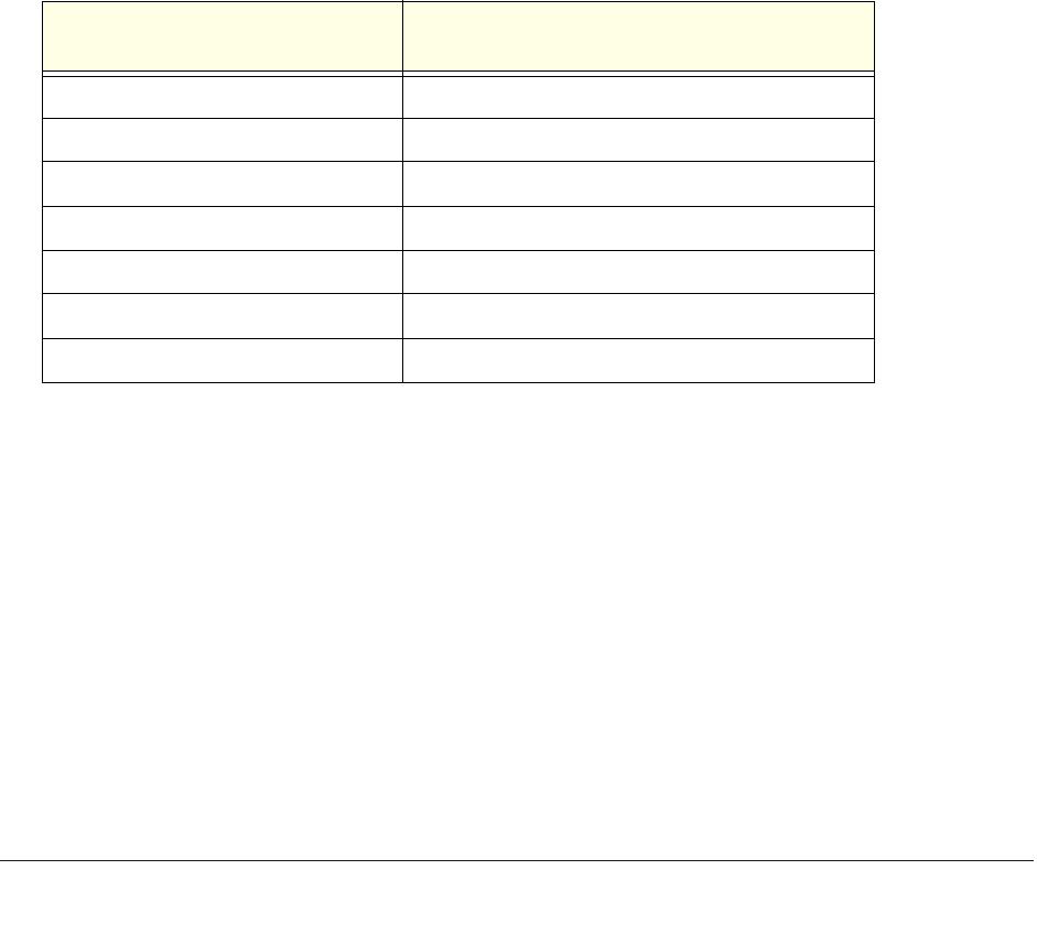
Notification of Compliance
146
D6200 WiFi Modem Router
Caution:
The device for the band 5150-5250 MHz is only for indoor usage to reduce po-tential for harmful interference to
co-channel mobile satellite systems.
Ce dispositif est conforme à la norme CNR-210 d'Industrie Canada applicable aux appareils radio exempts de licence.
Son fonctionnement est sujet aux deux conditions suivantes: (1) le dispositif ne doit pas produire de brouillage
préjudiciable, et (2) ce dispositif doit accepter tout brouillage reçu, y compris un brouillage susceptible de provoquer un
fonctionnement indésirable.
NOTE IMPORTANTE: Déclaration d'exposition aux radiations:
Cet équipement est conforme aux limites d'exposition aux rayonnements IC établies pour un environnement non
contrôlé. Cet équipement doit être installé et utilisé avec un minimum de 20 cm de distance entre la source de
rayonnement et votre corps.
Avertissement:
Le dispositif fonctionnant dans la bande 5150-5250 MHz est réservé uniquement pour une utili-sation à l'intérieur afin
de réduire les risques de brouillage préjudiciable aux systèmes de satellites mobiles utilisant les mêmes canaux.
Interference Reduction Table
The following table shows the recommended minimum distance between NETGEAR equipment and household
appliances to reduce interference (in feet and meters).
Household Appliance Recommended Minimum Distance
(in feet and meters)
Microwave ovens 30 feet / 9 meters
Baby Monitor - Analog 20 feet / 6 meters
Baby Monitor - Digital 40 feet / 12 meters
Cordless phone - Analog 20 feet / 6 meters
Cordless phone - Digital 30 feet / 9 meters
Bluetooth devices 20 feet / 6 meters
ZigBee 20 feet / 6 meters

147
Index
A
AC power adapter input 14
access
remote 116
viewing logs 89, 90
access points 100
accessing remote computer 103
adding
custom services 109
guest network 38
priority rules 57
QoS policy 56
wireless devices 27
address reservation 55
ADSL microfilters 19
ADSL port 13
ADSL setup 49
advertisement period 118
alerts, emailing 83
applications, QoS for online gaming 57
approved USB devices 70
attached devices 32
authentication, required by mail server 83
automatic firmware checking 85
automatic Internet connection 44
B
back panel 13
backing up configuration 92
base station, setting up 102
blocking
inbound traffic 103
keywords and sites 77
services 78
box contents 11
C
cables, checking 131
changes not saved, router 137
compliance 144
configuration file 92
connecting wirelessly 18
country setting 43
crossover cable 133
CTS/RTS Threshold 97
custom service (port forwarding) 109
D
dashboard 26
data packets, fragmented 52
date and time 137
daylight savings time 137
default DMZ server 51
default factory settings 12, 93, 141
default gateway 88
denial of service (DoS) protection 76
device mode 123
devices, attached 32
DHCP server 54, 88
DHCP setting 87
DMZ server 51
DNS addresses
primary 31
troubleshooting 135
DNS servers 104
Domain Name Server (DNS) addresses 31, 87
DSL port LED 15
Dynamic DNS 112
E
electromagnetic emissions 143
email notices 83
erasing configuration 93
Ethernet cables, checking 131
Ethernet LED, troubleshooting 132, 133
F
factory default settings
list of 141
resetting 12
restoring 93

148
D6200 WiFi Modem Router
file sharing 63
firewall settings 76
firmware version 86
firmware, upgrading 25, 85
fragmentation length 97
fragmented data packets 52
front panel 14, 17
G
games, online, QoS for 57
gateway IP address 31
genie, NETGEAR
advanced settings 42
basic settings 29
setup, initial 24
using, after installation 25
guest networks 38, 89
H
host name 30
host, trusted 77
I
inbound traffic, allowing or blocking 103
Internet connection
IPv6 119
setting up 30
troubleshooting 134
Internet port 44, 86
Internet port LEDs 15, 132
Internet Relay Chat (IRC) 105
Internet service provider (ISP)
account information 23
DSL synchronization 15
Internet Basic Settings screen fields 30
Internet services, blocking access 78
interval, poll 87
IP addresses
current 87
DHCP 23
dynamic 112
reserved 55
IP subnet mask 87
IPv6 Internet connection 119
K
keywords 77
L
LAN port
QoS for 59
settings 86
LAN ports 13
LAN setup 53
language setting 43
large files, sharing 64
lease, DHCP 88
LEDs 14, 17
troubleshooting 132
verifying cabling 21
Live Parental Controls 33
local servers, port forwarding to 107
logging in 23, 25
logs
emailing 83
viewing 89, 90
M
MAC addresses
current 86
QoS for 59
mail server, outgoing 83
maintenance settings 84
managing router remotely 116
media server, setting router as 69
menus, described 26
metric value 115
microfilters 19
mixed mode security options 39
Modem mode 123
MTU size 51
multicasting 54
N
NAT (Network Address Translation) 51, 104
NETGEAR genie
advanced settings 42
basic settings, initial 29
setup, initial 24
using, after installation 25
Network Time Protocol (NTP) 137
networks
correct settings, checking 131
guest 38, 89
restarting 131

149
D6200 WiFi Modem Router
O
On/Off button 13
On/Off LED 15
one-line ADSL microfilter 19
outgoing mail server 83
P
packets, fragmented 52
Parental Controls 33
passphrases, changing 38
passwords
recovering 94
restoring 138
photos, sharing 63
poll interval 87
port filtering 78
port forwarding 103, 106, 107
port numbers 78
port status 87
port triggering 103, 105, 107, 110
ports, back panel 13
positioning the router 18
power adapter, AC 14
Power LED, troubleshooting 132
PPPoE (PPP over Ethernet) 135
Preamble mode 97
preset security
about 35
passphrase 38
primary DNS addresses 31
printing files and photos 63
prioritizing traffic 56
Push ’N’ Connect 27
Q
QoS (Quality of Service) 56
R
radio, wireless 97
range of wireless connections 18
ReadySHARE access 62, 66
ReadySHARE printing 72
recovering admin password 94
releasing connection status 88
remote management 116
renewing connection status 88
repeater units 102
reserved IP adresses 55
restarting network 131
restoring
configuration file 92
default factory settings 138
router interface, described 26
Router mode 123
router status, viewing 86
S
scheduling keyword and service blocking 82
secondary DNS 31
security 35, 76
security options 39
security PIN 46
sending logs by email 83
services, blocking 78
Setup Wizard 43, 44
sharing files 63
sites, blocking 77
SMTP server 83
specifications, technical 141
splitters 19
SSID, described 37
static routes 113
status, router, viewing 86
subnet mask 87
system up time 87
T
technical specifications 141
technical support 2
Temporal Key Integrity Protocol (TKIP) 39
time of day 137
time to live, advertisement 118
time-out, port triggering 111
trademarks 2
traffic metering 119
troubleshooting 130
date or time incorrect 137
log in access 134
router changes not saved 137
trusted host 77
two-line ADSL microfilter 19
U
Universal Plug and Play (UPnP) 117

150
D6200 WiFi Modem Router
up time, system 87
upgrading firmware 25, 85
USB
advanced configuration 67
advanced settings 117
basic storage settings 65
drive requirements 62
file sharing 63
ReadySHARE access 62, 66
remote computer connection 71
specifying approved devices 70
unmounting a USB drive 68
USB devices, approved 70
USB port LED 16
USB printer 72, 74
user-defined services 81
W
WAN IP address, troubleshooting 134
WAN setup 50
wireless channel 37
wireless connections, troubleshooting 137
wireless connectivity 18
wireless devices, adding to the network 27
Wireless Distribution System (WDS) 100, 101
Wireless LEDs
front panel 16, 17
troubleshooting 133, 134
wireless mode 37
wireless network name (SSID), broadcasting 37
wireless network settings 37
wireless radio 97
wireless repeating 100, 101
base station 102
repeater unit 102
wireless security options 39
wireless settings 35, 89
checking for correct 131
SSID broadcast 37
WMM (Wi-Fi Multimedia) 56
WPA encryption 39
WPA2 encryption 39
WPA2-PSK encryption 39
WPA-PSK encryption 39
WPA-PSK/WPA2-PSK mixed mode 39
WPS (WiFi Protected Setup) 27, 45
WPS button 27
WPS LED 17
WPS-PSK encryption 39
WPS-PSK+ WPA2-PSK encryption 39
wrong date or time 137