Netgear orporated FWG114PV2 ProSafe 802.11g Wireless Firewall/Print Server User Manual FullManual
Netgear Incorporated ProSafe 802.11g Wireless Firewall/Print Server FullManual
Contents
- 1. Users Manual Part 1
- 2. Users Manual Part 2
- 3. Users Manual Part 3
Users Manual Part 2

Reference Manual for the ProSafe Wireless 802.11g Firewall/Print Server Model FWG114P
Firewall Protection and Content Filtering 6-3
March 2004, 202-10027-01
To delete a keyword or domain, select it from the list, click Delete Keyword, then click Apply.
Keyword application examples:
• If the keyword "XXX" is specified, the URL <http://www.badstuff.com/xxx.html> is blocked,
as is the newsgroup alt.pictures.XXX.
• If the keyword “.com” is specified, only Web sites with other domain suffixes (such as .edu or
.gov) can be viewed.
• If you want to block all Internet browsing access, enter the keyword “.”.
Up to 255 entries are supported in the Keyword list.
To specify a Trusted User, enter that computer’s IP address in the Trusted User box and click
Apply. You may specify one Trusted User, which is a computer that will be exempt from blocking
and logging. Since the Trusted User will be identified by an IP address, you should configure that
computer with a fixed or reserved IP address.
Services and Rules Regulate Inbound and Outbound Traffic
The ProSafe Wireless 802.11g Firewall/Print Server Model FWG114P firewall lets you regulate
what ports are available to the various TCP/IP protocols. Follow these two steps to configure
inbound or outbound traffic:
1. Define a Service
2. Set up an Inbound or Outbound Rule that uses the Service
These steps are discussed below.
Defining a Service
Services are functions performed by server computers at the request of client computers. For
example, Web servers serve Web pages, time servers serve time and date information, and game
hosts serve data about other players’ moves. When a computer on the Internet sends a request for
service to a server computer, the requested service is identified by a service or port number. This
number appears as the destination port number in the transmitted IP packets. For example, a packet
that is sent with destination port number 80 is an HTTP (Web server) request.

Reference Manual for the ProSafe Wireless 802.11g Firewall/Print Server Model FWG114P
6-4 Firewall Protection and Content Filtering
March 2004, 202-10027-01
The service numbers for many common protocols are defined by the Internet Engineering Task
Force (IETF) and published in RFC1700, “Assigned Numbers.” Service numbers for other
applications are typically chosen from the range 1024 to 65535 by the authors of the application.
Although the FWG114P already holds a list of many service port numbers, you are not limited to
these choices. Use the Services menu to add additional services and applications to the list for use
in defining firewall rules. The Services menu shows a list of services that you have defined.
To define a new service, first you must determine which port number or range of numbers is used
by the application. This information can usually be determined by contacting the publisher of the
application or from user groups of newsgroups. When you have the port number information, go
the Services menu and click on the Add Custom Service button. The Add Services menu will
appear.
To add a service,
1. Enter a descriptive name for the service so that you will remember what it is.
2. Select whether the service uses TCP or UDP as its transport protocol.
If you can’t determine which is used, select both.
3. Enter the lowest port number used by the service.
4. Enter the highest port number used by the service.
If the service only uses a single port number, enter the same number in both fields.
5. Click Apply.
The new service will now appear in the Services menu, and in the Service name selection box in
the Rules menu.
Using Inbound/Outbound Rules to Block or Allow Services
Firewall rules are used to block or allow specific traffic passing through from one side of the
wireless firewall/print server to the other. Inbound rules (WAN to LAN) restrict access by
outsiders to private resources, selectively allowing only specific outside users to access specific
resources. Outbound rules (LAN to WAN) determine what outside resources local users can have
access to.
A firewall has two default rules, one for inbound traffic and one for outbound. The default rules of
the FWG114P are:
• Inbound: Block all access from outside except responses to requests from the LAN side.
• Outbound: Allow all access from the LAN side to the outside.
Reference Manual for the ProSafe Wireless 802.11g Firewall/Print Server Model FWG114P
Firewall Protection and Content Filtering 6-5
March 2004, 202-10027-01
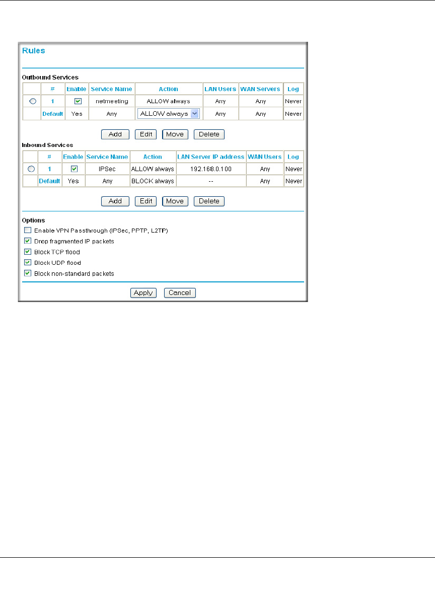
These default rules are shown in the Rules table of the Rules menu in Figure 6-2:
Figure 6-2: Rules menu
You can define additional rules that will specify exceptions to the default rules. By adding custom
rules, you can block or allow access based on the service or application, source or destination IP
addresses, and time of day. You can also choose to log traffic that matches or does not match the
rule you have defined.
To create a new rule, click the Add button.
To edit an existing rule, select its button on the left side of the table and click Edit.
To delete an existing rule, select its button on the left side of the table and click Delete.
To move an existing rule to a different position in the table, select its button on the left side of the
table and click Move. At the script prompt, enter the number of the desired new position and click
OK.
An example of the menu for defining or editing a rule is shown in Figure 6-3. The parameters are:

Reference Manual for the ProSafe Wireless 802.11g Firewall/Print Server Model FWG114P
6-6 Firewall Protection and Content Filtering
March 2004, 202-10027-01
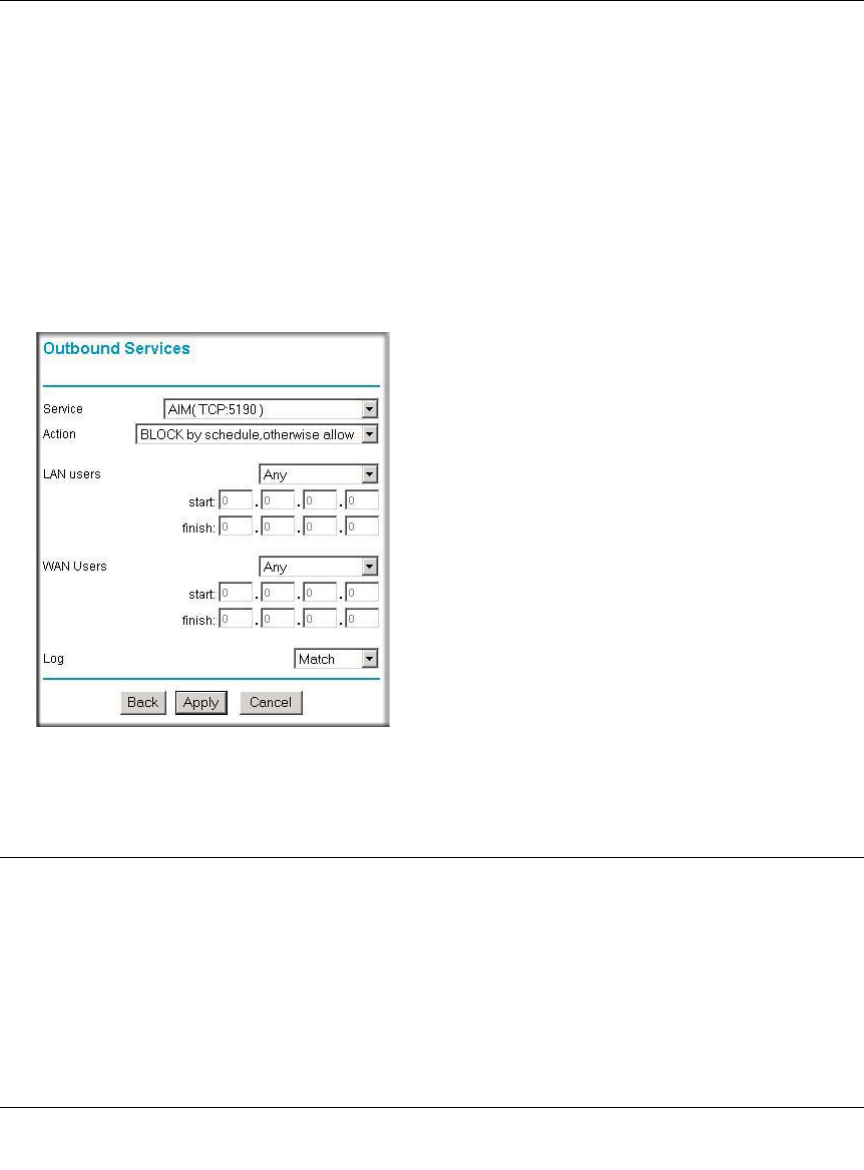
• Service. From this list, select the application or service to be allowed or blocked. The list
already displays many common services, but you are not limited to these choices. Use the
Services menu to add any additional services or applications that do not already appear.
• Action. Choose how you would like this type of traffic to be handled. You can block or allow
always, or you can choose to block or allow according to the schedule you have defined in the
Schedule menu.
• Source Address. Specify traffic originating on the LAN (outbound) or the WAN (inbound),
and choose whether you would like the traffic to be restricted by source IP address. You can
select Any, a Single address, or a Range. If you select a range of addresses, enter the range in
the start and finish boxes. If you select a single address, enter it in the start box.
• Destination Address.The Destination Address will be assumed to be from the opposite (LAN
or WAN) of the Source Address. As with the Source Address, you can select Any, a Single
address, or a Range unless NAT is enabled and the destination is the LAN. In that case, you
must enter a Single LAN address in the start box.
• Log. You can select whether the traffic will be logged. The choices are:
– Never - no log entries will be made for this service.
– Match - traffic of this type which matches the parameters and action will be logged.
Examples of Using Services and Rules to Regulate Traffic
Use the examples to see how you combine Services and Rules to regulate how the TCP/IP
protocols are used on your firewall to enable either blocking or allowing specific Internet traffic on
your wireless firewall/print server.
Inbound Rules (Port Forwarding)
Because the FWG114P uses Network Address Translation (NAT), your network presents only one
IP address to the Internet, and outside users cannot directly address any of your local computers.
However, by defining an inbound rule, also known as port forwarding, you can make a local server
(for example, a Web server or game server) visible and available to the Internet. The rule tells the
router to direct inbound traffic for a particular service to one local server based on the destination
port number. This is also known as port forwarding.
Reference Manual for the ProSafe Wireless 802.11g Firewall/Print Server Model FWG114P
Firewall Protection and Content Filtering 6-7
March 2004, 202-10027-01
Follow these guidelines when setting up port forwarding inbound rules:
• If your external IP address is assigned dynamically by your ISP, the IP address may change
periodically as the DHCP lease expires. Consider using the Dyamic DNS feature in the
Advanced menus so that external users can always find your network.
• If the IP address of the local server computer is assigned by DHCP, it may change when the
computer is rebooted. To avoid this, use the Reserved IP address feature in the LAN IP menu
to keep the computer’s IP address constant.
• Local computers must access the local server using the local LAN address of the computer.
Attempts by local computers to access the server using the external WAN IP address will fail.
Remember that allowing inbound services opens holes in your FWG114P Wireless Firewall/Print
Server. Only enable those ports that are necessary for your network. Following are two application
examples of inbound rules:
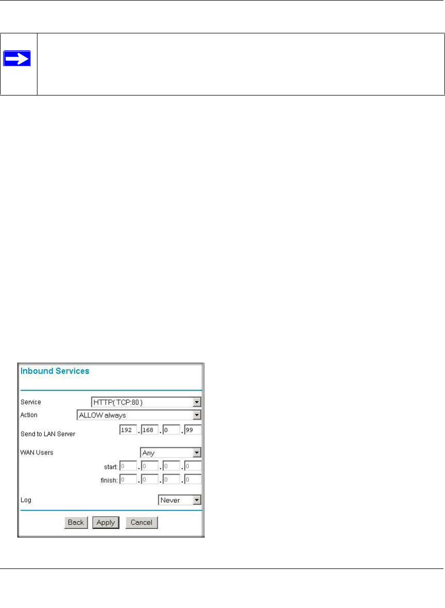
Example: Port Forwarding to a Local Public Web Server
If you host a public Web server on your local network, you can define a rule to allow inbound Web
(HTTP) requests from any outside IP address to the IP address of your Web server any time of day.
Figure 6-3: Rule example: A Local Public Web Server
Note: Some home broadband accounts do not allow you to run any server processes
(such as a Web or FTP server). Your ISP may check for servers and suspend your
account if it discovers active servers at your location. If you are unsure, refer to the
Acceptable Use Policy of your ISP.
Reference Manual for the ProSafe Wireless 802.11g Firewall/Print Server Model FWG114P
6-8 Firewall Protection and Content Filtering
March 2004, 202-10027-01
This rule is shown in Figure 6-3.
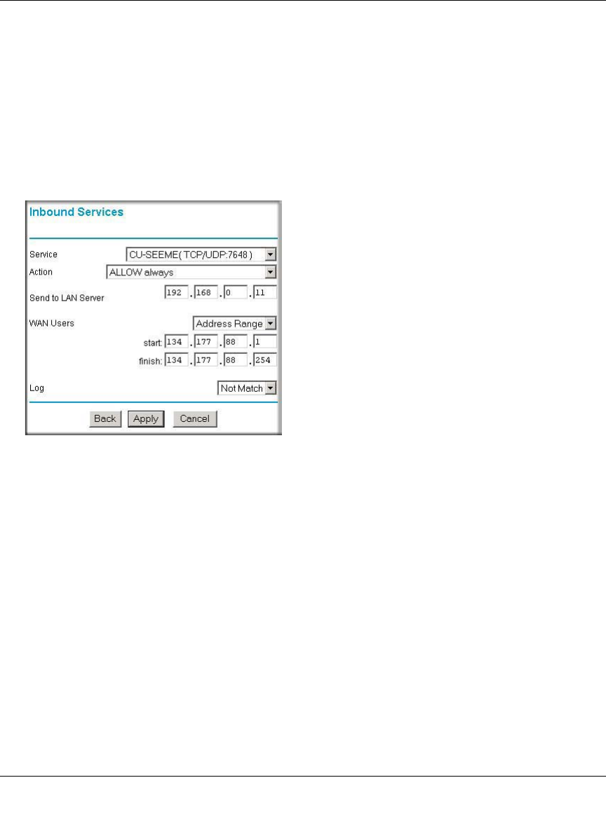
Example: Port Forwarding for Videoconferencing
If you want to allow incoming videoconferencing to be initiated from a restricted range of outside
IP addresses, such as from a branch office, you can create an inbound rule. In the example shown
in Figure 6-4, CU-SeeMe is a predefined service and its connections are allowed only from a
specified range of external IP addresses. In this case, we have also specified logging of any
incoming CU-SeeMe requests that do not match the allowed parameters.
Figure 6-4: Rule example: Videoconference from Restricted Addresses
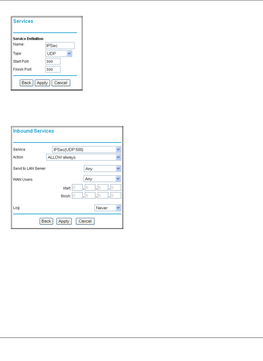
Example: Port Forwarding for VPN Tunnels when NAT is Off
If you want to allow incoming VPN IPSec tunnels to be initiated from outside IP addresses
anywhere on the Internet when NAT is off, first create a service and then an inbound rule.
Reference Manual for the ProSafe Wireless 802.11g Firewall/Print Server Model FWG114P
Firewall Protection and Content Filtering 6-9
March 2004, 202-10027-01
Figure 6-5: Service example: port forwarding for VPN when NAT is Off
In the example shown in Figure 6-5, UDP port 500 connections are defined as the IPSec service.
Figure 6-6: Inbound rule example: VPN IPSec when NAT is off
In the example shown in Figure 6-6, VPN IPSec connections are allowed any internal LAN IP
address.
Outbound Rules (Service Blocking or Port Filtering)
The FWG114P allows you to block the use of certain Internet services by computers on your
network. This is called service blocking or port filtering. You can define an outbound rule to block
Internet access from a local computer based on:
• IP address of the local computer (source address)
Reference Manual for the ProSafe Wireless 802.11g Firewall/Print Server Model FWG114P
6-10 Firewall Protection and Content Filtering
March 2004, 202-10027-01
• IP address of the Internet site being contacted (destination address)
•Time of day
• Type of service being requested (service port number)
Outbound Rule Example: Blocking Instant Messaging
If you want to block Instant Messenger usage by employees during working hours, you can create
an outbound rule to block that application from any internal IP address to any external address
according to the schedule that you have created in the Schedule menu. You can also have the router
log any attempt to use Instant Messenger during that blocked period.
Figure 6-7: Rule example: Blocking Instant Messenger
Other Rules Considerations
The order of precedence of rules is determined by the position of the rule on a list of many rules.
Also, there are optional Rules settings you can configure. These topics are presented here.
Reference Manual for the ProSafe Wireless 802.11g Firewall/Print Server Model FWG114P
Firewall Protection and Content Filtering 6-11
March 2004, 202-10027-01
Order of Precedence for Rules
As you define new rules, they are added to the tables in the Rules menu. For any traffic attempting
to pass through the firewall, the packet information is subjected to the rules in the order of the
entries in the Rules Table, beginning at the top and proceeding to the default rules at the bottom. In
some cases, the order of precedence of two or more rules may be important in determining the
disposition of a packet. The Move button allows you to relocate a defined rule to a new position in
the table.
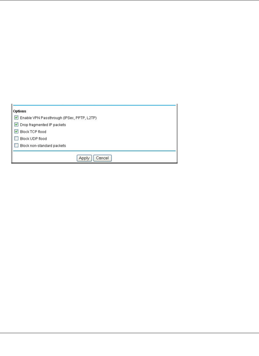
Rules Menu Options
Use the Options checkboxes to enable the following:
• Enable VPN Passthrough (IPSec, PPTP, L2TP)
If LAN users need to use VPN (Virtual Private Networking) software on their computer, and
connect to remote sites or servers, enable this checkbox. This will allow the VPN protocols
(IPSec, PPTP, L2TP) to be used. If this checkbox is not checked, these protocols are blocked.
•Drop fragmented IP packets
If checked, all fragmented IP packets will be dropped (discarded). Normally, this should NOT
be checked.
•Block TCP flood
If checked, when a TCP flood attack is detected, the port used will be closed, and no traffic
will be able to use that port.
•Block UDP flood
If checked, when a UDP flood attack is detected, all traffic from that IP address will be
blocked.
•Block non-standard packets
If checked, only known packet types will be accepted; other packets will be blocked. The
known packet types are TCP, UDP, ICMP, ESP, and GRE. Note that these are packet types, not
protocols.
Reference Manual for the ProSafe Wireless 802.11g Firewall/Print Server Model FWG114P
6-12 Firewall Protection and Content Filtering
March 2004, 202-10027-01
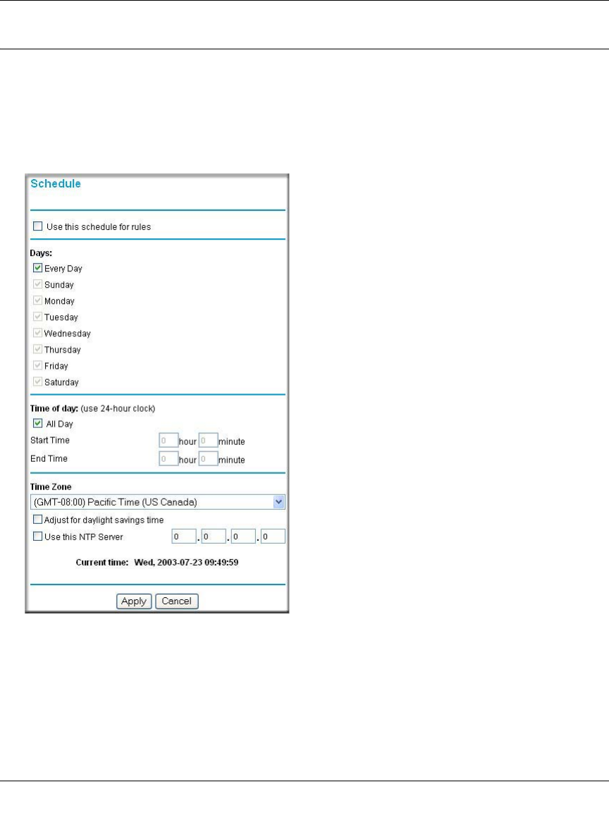
Using a Schedule to Block or Allow Content or Traffic
If you enabled content filtering in the Block Sites menu, or if you defined an outbound rule to use
a schedule, you can set up a schedule for when blocking occurs or when access is restricted. The
router allows you to specify when blocking will be enforced by configuring the Schedule tab
shown below.
Figure 6-8: Schedule menu
To block keywords or Internet domains based on a schedule, select Every Day or select one or
more days. If you want to limit access completely for the selected days, select All Day. Otherwise,
If you want to limit access during certain times for the selected days, type a Start Time and an End
Time.

Reference Manual for the ProSafe Wireless 802.11g Firewall/Print Server Model FWG114P
Firewall Protection and Content Filtering 6-13
March 2004, 202-10027-01
Note: Enter the values in 24-hour time format. For example, 10:30 am would be 10 hours and 30
minutes and 10:30 pm would be 22 hours and 30 minutes.
Be sure to click Apply when you have finished configuring this menu.
Setting the Time Zone
The FWG114P Wireless Firewall/Print Server uses the Network Time Protocol (NTP) to obtain the
current time and date from one of several Network Time Servers on the Internet. In order to
localize the time for your log entries, you must specify your Time Zone:
• Time Zone. Select your local time zone. This setting will be used for the blocking schedule
and for time-stamping log entries.
• Daylight Savings Time. Select this check box for daylight savings time.
Note: If your region uses Daylight Savings Time, you must manually select Adjust for
Daylight Savings Time on the first day of Daylight Savings Time, and unselect it at the end.
Enabling Daylight Savings Time will add one hour to the standard time.
Be sure to click Apply when you have finished configuring this menu.
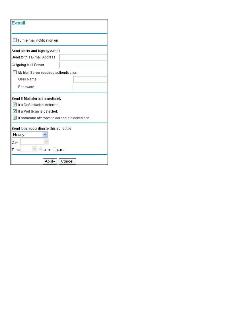
Getting E-Mail Notifications of Event Logs and Alerts
In order to receive logs and alerts by e-mail, you must provide your e-mail information in the
E-Mail subheading:
Reference Manual for the ProSafe Wireless 802.11g Firewall/Print Server Model FWG114P
6-14 Firewall Protection and Content Filtering
March 2004, 202-10027-01
Figure 6-9: E-mail menu
•Turn e-mail notification on. Select this check box if you want to receive e-mail logs and
alerts from the router.
•Send alerts and logs by e-mail. If you enable e-mail notification, these boxes cannot be
blank. Enter the name or IP address of your ISP’s outgoing (SMTP) mail server (such as
mail.myISP.com). You may be able to find this information in the configuration menu of your
e-mail program. Enter the e-mail address to which logs and alerts will be sent. This e-mail
address will also be used as the From address. If you leave this box blank, log and alert
messages will not be sent via e-mail. Check “My Mail Server requires authentication” if you
need to log in to your SMTP server in order to send e-mail. If this is checked, you must enter
the login name and password for your mail server.
Tip: You used this information when you set up your e-mail program. If you cannot remember
it, check the settings in your e-mail program.
•Send E-mail alerts immediately. You can specify that logs are immediately sent to the
specified e-mail address when any of the following events occur:

Reference Manual for the ProSafe Wireless 802.11g Firewall/Print Server Model FWG114P
Firewall Protection and Content Filtering 6-15
March 2004, 202-10027-01
– If a Denial of Service attack is detected.
– If a Port Scan is detected.
– If a user on your LAN attempts to access a website that you blocked using Keyword
blocking.
•Send logs according to this schedule. You can specify that logs are sent to you according to a
schedule. Select whether you would like to receive the logs Hourly, Daily, Weekly, When Full,
or None for no logs. Depending on your selection, you may also need to specify:
– Day for sending log
Relevant when the log is sent weekly or daily.
– Time for sending log
Relevant when the log is sent daily or weekly.
If the Weekly, Daily or Hourly option is selected and the log fills up before the specified
period, the log is automatically e-mailed to the specified e-mail address. After the log is sent,
the log is cleared from the router’s memory. If the router cannot e-mail the log file, the log
buffer may fill up. In this case, the router overwrites the log and discards its contents.
Be sure to click Apply when you have finished configuring this menu.
Reference Manual for the ProSafe Wireless 802.11g Firewall/Print Server Model FWG114P
6-16 Firewall Protection and Content Filtering
March 2004, 202-10027-01
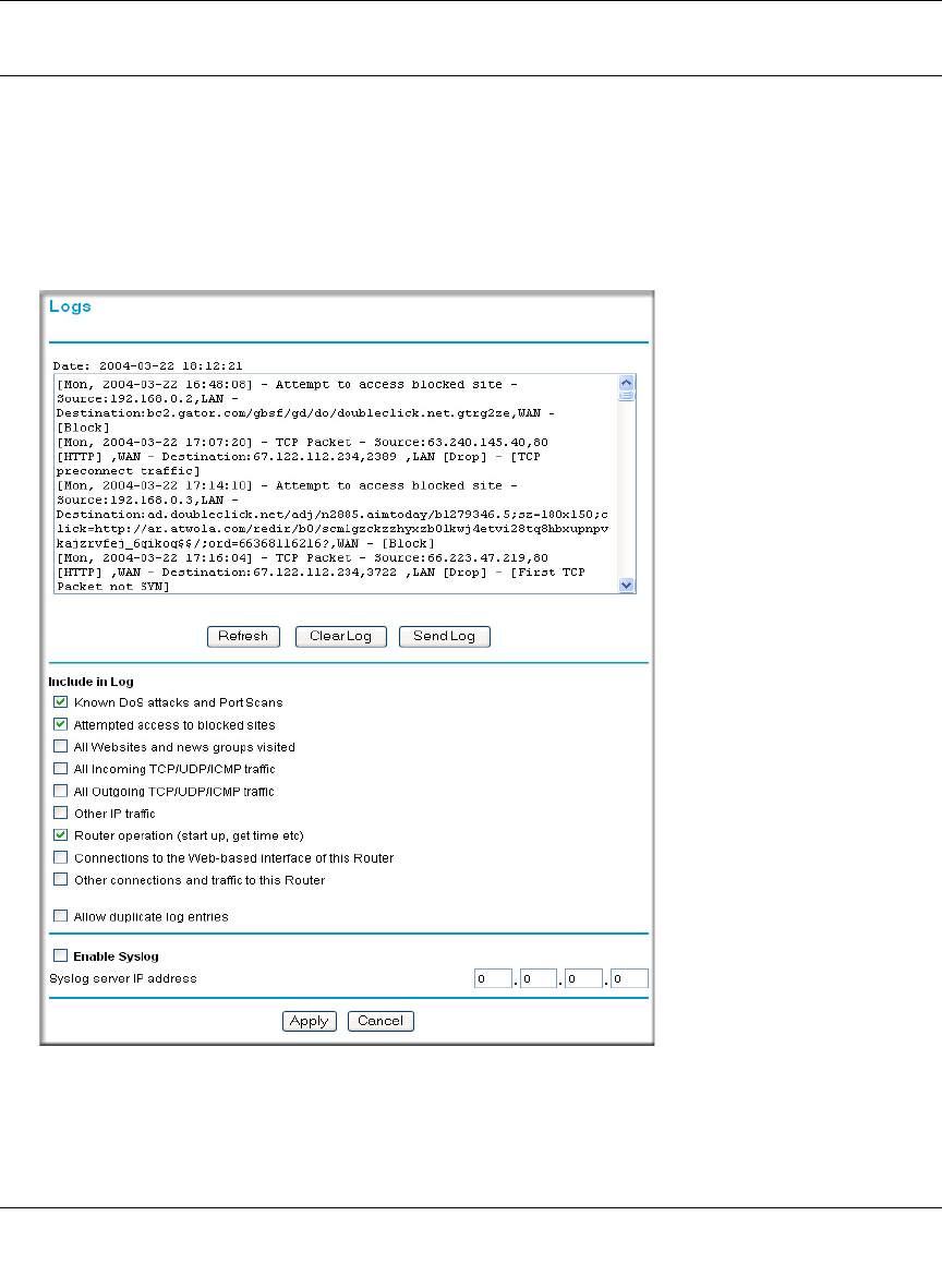
Viewing Logs of Web Access or Attempted Web Access
The router will log security-related events, such as denied incoming and outgoing service requests,
hacker probes, and administrator logins. If you enable content filtering in the Block Sites menu,
the Log page will also show you when someone on your network tries to access a blocked site. If
you enabled e-mail notification, you will receive these logs in an e-mail message. If you do not
have e-mail notification enabled, you can view the logs here.
Figure 6-10: Logs menu
See Appendix D, “Firewall Log Formats” for a full explanation of log entry formats.
Reference Manual for the ProSafe Wireless 802.11g Firewall/Print Server Model FWG114P
Firewall Protection and Content Filtering 6-17
March 2004, 202-10027-01
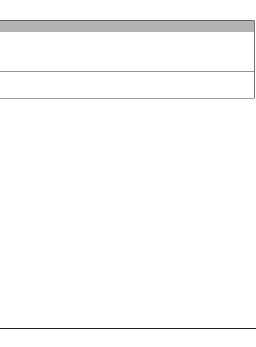
Log action buttons are described in Table 6-1.
What to Include in the Event Log
Use these checkboxes to determine which events are included in the log. Checking all options will
increase the size of the log, so it is good practice to disable any events which are not really
required.
• All Websites and news groups visited - If checked, all visited websites and newsgroups are
logged.
• All Incoming TCP/UDP/ICMP traffic - If checked, all incoming TCP/UDP/ICMP connections
and traffic is logged.
• All Outgoing TCP/UDP/ICMP traffic - If checked, all outgoing TCP/UDP/ICMP connections
and traffic is logged.
• Other IP traffic - If checked, all other traffic (IP packets which are not TCP, UDP, or ICMP) is
logged.
• Router operation (start up, get time, etc.) - If checked, Router operations, such as starting up
and getting the time from the Internet Time Server, are logged.
• Connection to the Web-based interface of this Router - If checked, Administrator connections
to the Web-based interface will be logged.
• Other connections and traffic to this Router - If checked, this will log traffic sent to this Router
(rather than through this Router to the Internet).
• Allow duplicate log entries - If checked, then events or packets which fall within more than
one (1) category above will have a log entry for each category in which they belong. This will
generate a large number of log entries. If unchecked, then events or packets will only be
logged once. Usually, this should be left unchecked.
Logging programs are available for Windows, Macintosh, and Linux computers.
Table 6-1. Log action buttons
Field Description
Refresh Refreshes the log screen.
Clear Log Clears the log entries.
Send Log E-mails the log immediately.

Reference Manual for the ProSafe Wireless 802.11g Firewall/Print Server Model FWG114P
6-18 Firewall Protection and Content Filtering
March 2004, 202-10027-01
Enable one of these three options, as required:
• Disable - select this if you do not have a Syslog server.
• Broadcast on LAN - the Syslog data is broadcast, rather than sent to a specific Syslog server.
Use this if your Syslog Server does not have a fixed IP address.
• Send to this Syslog server IP address - If your Syslog server has a fixed IP address, select this
option, and enter the IP address of your Syslog server.

Print Server 7-1
March 2004, 202-10027-01
Chapter 7
Print Server
This chapter describes how to install and configure the print server in your ProSafe Wireless
802.11g Firewall/Print Server Model FWG114P.
Printing Options
The FWG114P supports these methods for printing:
•For Windows XP and 2000 Only: TCP/IP Line Printer Remote (LPR) Printing
— No software needs to be installed
— Windows XP or 2000 users can print directly to the firewall. Print jobs are spooled
(queued) on each computer. The computer sends the print job directly to the LAN IP
address of the FWG114P.
•For Windows 95/98/Me, NT4.0, 2000, and XP: Netgear Printer Port Driver
— Install the Netgear Printer Port Driver on Each computer.
— After installing the Print Port Driver from the Resource CD for the ProSafe Wireless
802.11g Firewall/Print Server Model FWG114P (SW-10023-02) Windows users can print
directly to the firewall. Print jobs are spooled (queued) on each computer.
• For Macintosh computers: LPR printing
— No software needs to be installed
— LPR printing can be set up on any Macintosh that has Desktop Printing installed or
available. Desktop Printing is supported on MacOS versions beginning from 8.1.
LaserWriter8 version 8.5.1 or higher is also required.
•For Windows NT 4.0 Server or 2000 Server: LPD/LPR Printing
— No software needs to be installed
— If using Windows NT 4.0 Server or Windows 2000 Server, LPD/LPR printing can be used.
No software needs to be installed on either the Windows Server or each client computer.
Print jobs will be spooled (queued) on the Windows Server, and can be managed using the
standard Windows Server tools.
Reference Manual for the ProSafe Wireless 802.11g Firewall/Print Server Model FWG114P
7-2 Print Server
March 2004, 202-10027-01
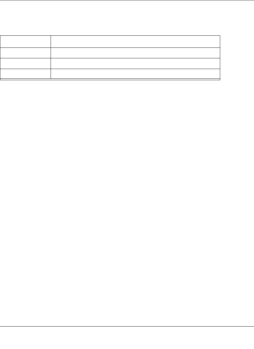
For Windows XP and 2000, Use TCP/IP LPR Printing
Follow these instructions to set up TCP/IP printing on your Windows XP and 2000 PCs.
Install the FWG114P, connect your printer
to the USB port on the FWG114P, and run
the Windows Add Printer Wizard.
a. Follow the instructions in the printed
Installation Guide or this manual to
install your FWG114P. Connect your
printer to the USB port on the back of the
FWG114P.
b. From the Windows Start menu of a
computer connected to the FWG114P,
click Printers and Faxes.
c. Click Add a printer. Click Next to
proceed.
d. Be sure to choose the Local printer
attached to this computer option.
Click Next to proceed.
e. On the Select a Printer Port screen, be
sure to choose the Create a new port:
option.
From the Type of port: drop-down list,
be sure to select Standard TCP/IP
Port.
Click Next to proceed.
This will start the Add Standard TCP/IP
Printer Port Wizard.
Add Printer Wizard
Local or Network Printer screen
Select a Printer Port screen
Reference Manual for the ProSafe Wireless 802.11g Firewall/Print Server Model FWG114P
Print Server 7-3
March 2004, 202-10027-01
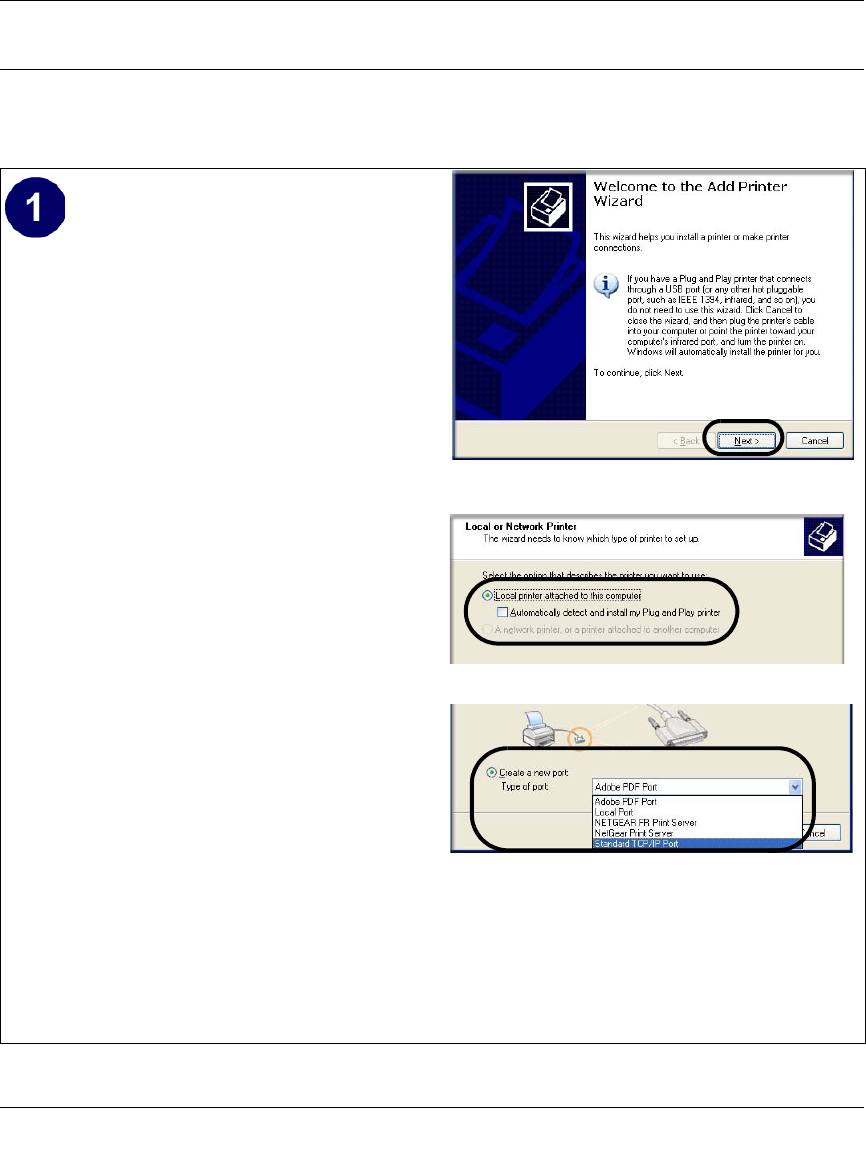
Complete the Add Standard TCP/IP Printer
Port Wizard.
a. Click Next to proceed with the Add
Standard TCP/IP Printer Port Wizard.
The Add Port screen will display.
b. From the Add Port screen, enter
192.168.0.1, the FWG114P default LAN
IP address, in the IP Address field.
Note: If you changed the default LAN IP
Address of the FWG114P, be sure to use
the address you assigned here. The Port
Name is automatically filled in.
Click Next to proceed.
c. In the Device Type section of the
Additional Port Information Required
screen, select Custom.
d. In the Custom selection, click Settings.
e. The Port Settings tab page opens. In the
Protocol section, select the LPR radio
button, and enter FWG114P as the
Queue Name in the LPR Settings
section. Click OK to close this tab page.
Click Next to proceed.
The Add Printer Wizard will now
prompt you to install the software for the
printer you attached to the FWG114P.
Add Standard TCP/IP Printer Port Wizard
Add Port Screen
Additional Port Information Required
Additional Port Information Required
Reference Manual for the ProSafe Wireless 802.11g Firewall/Print Server Model FWG114P
7-4 Print Server
March 2004, 202-10027-01
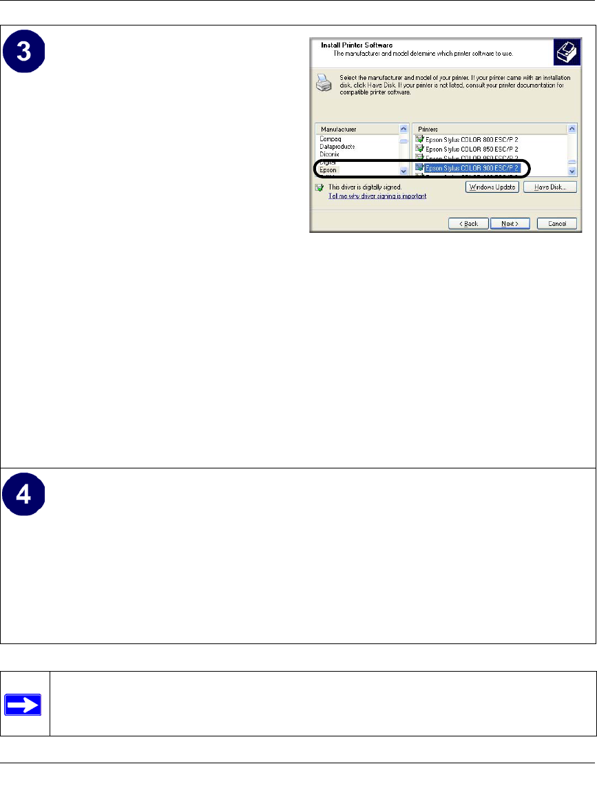
Identify the printer connected to FWG114P
USB printer port.
a. From the Install Printer Software screen
selection lists, find the manufacturer and
model of the printer you connected to the
USB port on the FWG114P.
Click Next to proceed.
If the printer software is already installed
on this computer, the Add Printer
Wizard will inform you and let you keep
the existing driver.
b. The Name Your Printer screen prompts
for a descriptive name and if you want it
to be the default. Enter your choices.
Click Next to proceed.
c. On the Printer Sharing screen, accept the
“Do not share this printer” option and
click Next to proceed.
Add Printer Wizard Install Printer Software page
If you do not see your make and model
printer in the lists, and you are connected
to the Internet, you can click the
Windows Update button to download
additional printer software from the
Microsoft Web site, or you can click the
Have Disk button to install the printer
software from a disk you have.
Print a test page to verify successful printing on your network.
a. Upon completion of the Add Printer Wizard, you will be prompted to print a test page.
b. Check the printer attached to the FWG114P to see that the test page printed successfully.
If you are unable to print a test page, see “Troubleshooting the Print Server“ on page -11.
Note: If two long files are sent to the printer at once, Windows will pop up a print failure
error message. This message can be ignored. The file will print once the printer finishes
printing the first file.
Reference Manual for the ProSafe Wireless 802.11g Firewall/Print Server Model FWG114P
Print Server 7-5
March 2004, 202-10027-01
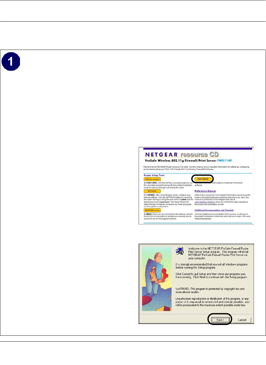
For Windows 95/98/Me, Use the Netgear Printer Port Driver
Follow these instructions to set up the Netgear Printer Port Drive on Windows 9x PCs.
Install the Netgear Printer Port Driver and
configuration utility software.
a. Follow the instructions in the printed
Installation Guide or this manual to
install your FWG114P.
b. Connect your printer to the USB port on
the back of the FWG114P.
c. Insert the Resource CD for the
FWG114P into the CD-ROM drive of a
computer connected to the FWG114P.
The CD main page shown at the right
will load.
d. Click the Print Server button.
Follow the instructions for running the
setup utility.
e. Click Next to proceed through the
Netgear Printer Port Installation Wizard
steps.
Note: Windows 2000 or XP may require
you to be logged on with administrator
rights.
Warning: If you are installing the Netgear
printer port driver on a Windows computer
where an Epson printer had been installed,
you must disable the Epson Spool
Manager. Failure to disable Epson Spool
Manager software will prevent the Netgear
printer port driver from operating.
To disable the Epson Spool Manager, run the
Epson Spool Manager, select Queue Setup
from the menu, click Use Print Manager
for this port, and click OK to exit.
FWG114P Resource CD
Netgear Printer Port Installation Wizard
Reference Manual for the ProSafe Wireless 802.11g Firewall/Print Server Model FWG114P
7-6 Print Server
March 2004, 202-10027-01
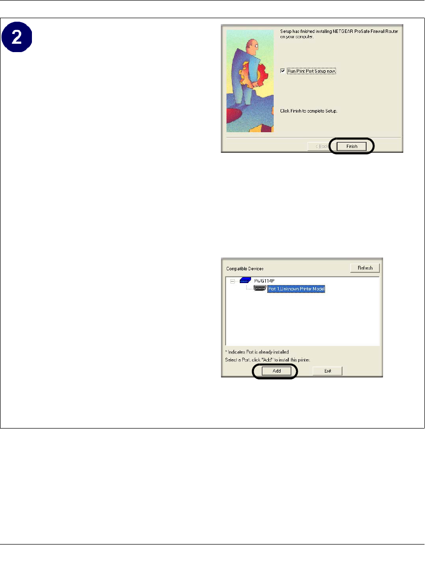
Set up the Netgear printer port driver.
a. Click Finish when the Installation
Wizard is done.
The Printer Port Setup utility displays,
and queries the network to locate the
print server in the FWG114P.
After a short delay, the Printer Port
Setup utility will display the port it finds
in the FWG114P print server.
b. Click Add to add this printer port to your
computer.
The Printer Port Setup utility will report
that Port FWG114P_P1 has been added
to the computer.
c. Click Exit to exit the Printer Port Setup
utility.
The Windows Add Printer Wizard
automatically runs.
Netgear Printer Port Installation Wizard
Note: Under Windows 95, you may
receive an error message stating that
SETUPAPI.DLL was not found. In this
case, you should upgrade your Internet
Explorer to version 5 or later.
Netgear Printer Port Setup Utility
Reference Manual for the ProSafe Wireless 802.11g Firewall/Print Server Model FWG114P
Print Server 7-7
March 2004, 202-10027-01
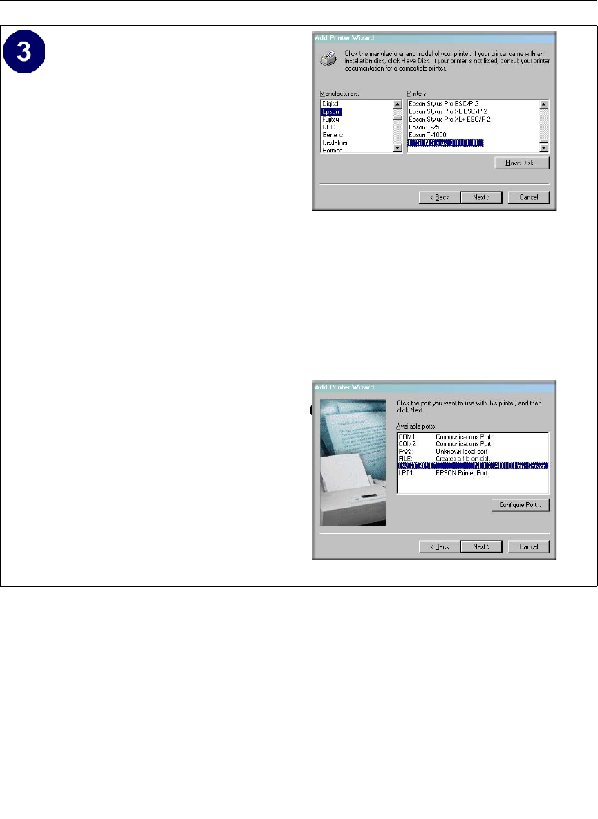
Identify the printer connected to the
FWG114P USB printer port.
a. From the Add Printer Wizard screen
selection lists, find the manufacturer and
model of the printer you connected to the
USB port on the FWG114P.
Click Next to proceed.
If the printer software is already installed
on this PC, the Add Printer Wizard will
inform you and let you keep the existing
driver.
b. Be sure to select the FWG114P_P1 port
in the Add Printer Wizard.
Click Next.
c. The Name Your Printer screen prompts
for a descriptive name and if you want it
to be the default. Enter your choices.
If prompted about Sharing, do not enable
Sharing.
Click Next to proceed and finish the Add
Printer Wizard steps.
Windows Add Printer Wizard
If you do not see your make and model printer in
the lists, and you are connected to the Internet,
you can click the Windows Update button to
download additional printer software from the
Microsoft Web site, or you can click the Have Disk
button to install the printer software from a disk
you have.
Windows Add Printer Wizard
Reference Manual for the ProSafe Wireless 802.11g Firewall/Print Server Model FWG114P
7-8 Print Server
March 2004, 202-10027-01
Printing from the Macintosh
Macintosh computers can connect to a TCP/IP network printer using the Line Printer Remote
(LPR) protocol. LPR printing can be set up on any Macintosh that has Desktop Printing installed
or available. Desktop Printing is supported on MacOS versions beginning from 8.1. LaserWriter8
version 8.5.1 or higher is also required.
To configure the Macintosh to use the print server, follow these steps:
1. From the Apple Extras folder, under Apple LaserWriter Software, launch the Desktop Printing
Utility. A new window titled New Desktop Printer appears.
2. Select LaserWriter 8 in the “With” drop-down menu.
3. Select Printer (LPR) and click OK. A new window called Untitled 1 will open.
4. If the PostScript Printer Description does not match your printer, click Change... and select
your actual printer.
If your printer model does not appear, click the Generic button.
5. Click OK to return to the Untitled 1 window.
6. In the LPR Printer Selection box, click Change...
Print a test page to verify successful printing on your network.
a. Upon completion of the Add Printer Wizard, print a test page.
– From the Windows Start menu, select Setup > Printers.
– Highlight the printer you just added.
– Right-click and the select Properties.
The printer properties dialog box opens to the General tab page.
– On the General tab page, click Print Test Page.
b. Check the printer attached to the FWG114P to see that the test page printed successfully.
If you are unable to print a test page, see “Troubleshooting the Print Server“ on page -11.

Reference Manual for the ProSafe Wireless 802.11g Firewall/Print Server Model FWG114P
Print Server 7-9
March 2004, 202-10027-01
7. In the Printer Address field, type the name or IP address of the FWG114P Wireless Firewall/
Print Server.
The IP address will usually be 192.168.0.1.
You can leave the Queue Name blank.
Click Verify to make sure your computer can see the printer.
You should see the IP address displayed above the button. If no IP Address appears, check that
you have correctly typed the queue name or IP Address.
Click OK to return to the Untitled 1 window.
8. At the bottom of the Untitled 1 dialog box, click Create....
When prompted, rename the printer with a descriptive name and click Save.
A printer icon should now appear on your desktop.
9. Quit the Desktop Printer Utility.
Windows Printer Port Management
• Print jobs can be managed from Windows. Open the Printers folder (Start -> Settings ->
Printers) and double-click any printer to see the current print jobs.
• To delete a port created by this setup program, use the Windows Delete Port facility:
a. Right-click any printer in the Printers folder, and select Properties.
b. Highlight the port you want to delete.
c. Use the Delete Port button to delete the port. This button is on either the Details or Ports
tab, depending on your version of Windows.
• If you change the printer attached to the FWG114P, run the Add Port program again and select
the new printer.
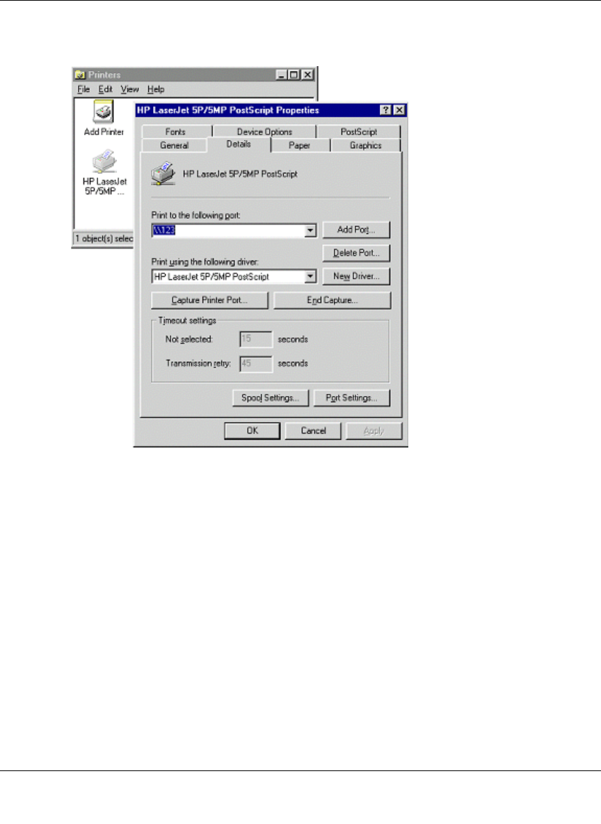
The options for the Print Port Driver are accessed via the Windows Port Settings button.
Use Start -> Settings -> Printers to open the Printers folder, then right-click the Printer and select
Properties. The Port Settings button is on either the Details or Port tab, depending on your version
of Windows. An example screen is shown below:
Reference Manual for the ProSafe Wireless 802.11g Firewall/Print Server Model FWG114P
7-10 Print Server
March 2004, 202-10027-01
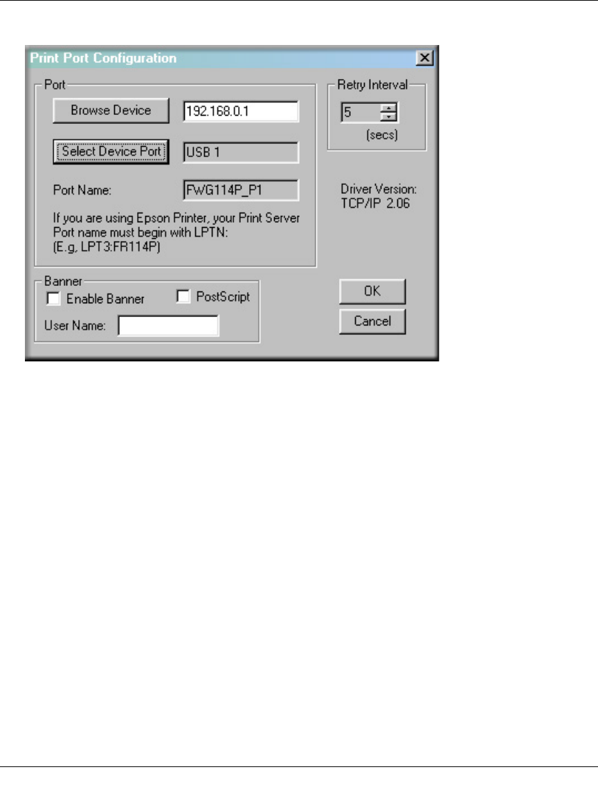
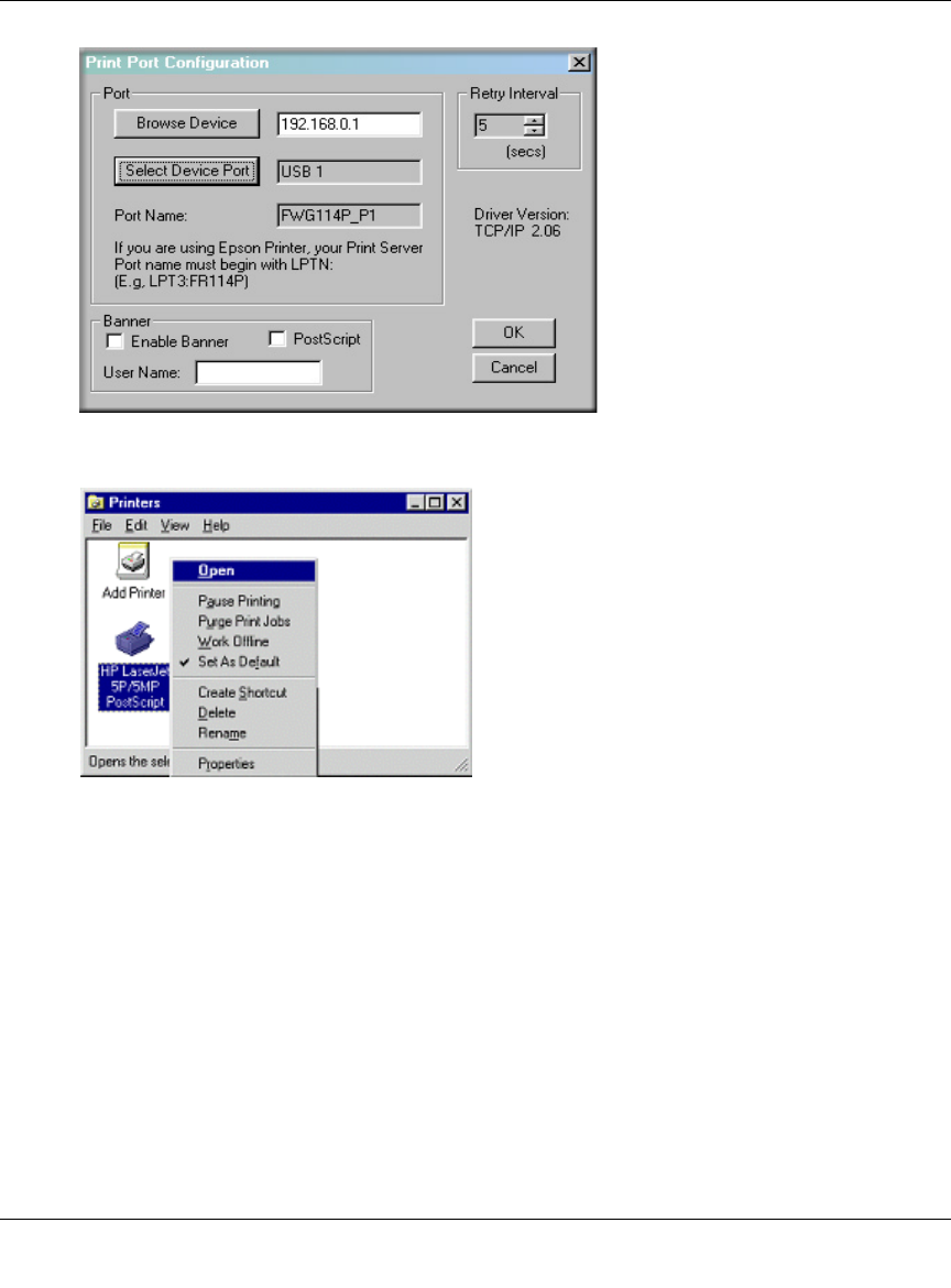
Figure 7-1: Print Port Configuration menu
Items shown on this screen are as follows:
•Port
If desired, click Browse Device to select a different device. The Select Device Port button
supports multi-port models, but the FWG114P Wireless Firewall/Print Server is a single-port
print server. The Port Name is shown in the Printer's Properties.
•Banner
Check this option to print a banner page before each print job. The User Name you enter will
be printed on the banner page. If using a PostScript Printer, check the PostScript box.
• Retry Interval
Determines how often Windows will poll the print server to establish a connection when the
printer is busy.
Reference Manual for the ProSafe Wireless 802.11g Firewall/Print Server Model FWG114P
Print Server 7-11
March 2004, 202-10027-01
Troubleshooting the Print Server
Question: When I tried to install the Printer Driver for Peer-to-Peer printing, I received an error
message and the installation was aborted.
Answer: This may be caused by an existing installation of the printer port software. Before
attempting another installation, remove the existing installation and restart your PC.
To remove an existing printer port installation:
a. Open Start -> Settings -> Control Panel -> Add/Remove Programs.
b. Look for an entry with a name like “NETGEAR ProSafe Firewall Router”, “NETGEAR
Print Server”, "Print Server Driver" or "Print Server Port".
c. Select this item, click Add/Remove, and confirm the deletion.
Question: I am using Windows 95. The Printer Driver installed and ran, but when I selected a port
and clicked Add, the printer was not installed.
Answer: Try installing the printer using the standard Windows tools, as follows:
a. From Start -> Settings, open the Printers folder, and start the Add Printer Wizard.
b. When prompted, select Network Printer and click Next.
Note: When the TCP/IP LPR configuration is used, if two long files are sent to the
printer at once, Windows will pop up a print failure error message. This message can be
ignored. The file will print once the printer finishes printing the first file. This does not
happen when the Netgear Printer Port driver is used.
Reference Manual for the ProSafe Wireless 802.11g Firewall/Print Server Model FWG114P
7-12 Print Server
March 2004, 202-10027-01
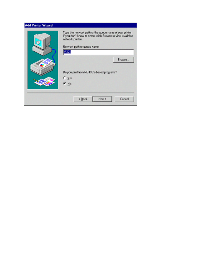
c. For Network Path or Queue, enter a dummy value, such as \\123, as shown below.
Select NO for “Do you print from MS-DOS-based programs?”.
d. Click Next.
Figure 7-2: Windows Add Printer Wizard
e. The printer wizard will display a message stating that "The Network Printer is off-line".
This is OK. Continue the Add Printer Wizard until finished.
f. When finished, go to Start -> Settings -> Printers. The new printer icon will be grayed out
indicating the printer is not ready.
Reference Manual for the ProSafe Wireless 802.11g Firewall/Print Server Model FWG114P
Print Server 7-13
March 2004, 202-10027-01
g. Right-click the new printer and select Properties. Then select the Details tab, as shown
below.
Figure 7-3: Windows Printer Properties
h. Click the Add Port button. On the resulting screen, select Other, then select the
NETGEAR Print Server Port as the port to add.
i. Click OK to see the Print Port Configuration screen.
j. Click the Browse Device button, select the firewall, and click OK.
Reference Manual for the ProSafe Wireless 802.11g Firewall/Print Server Model FWG114P
7-14 Print Server
March 2004, 202-10027-01
k. Click OK to return to the Printers folders, and right-click on the new printer. Make sure
that the Work Offline option is NOT checked.
l. From the printer Properties page, General tab, print a test page to confirm that the settings
work.
m. The new printer icon should no longer be grayed out, and the printer is ready for use.
Virtual Private Networking 8-1
March 2004, 202-10027-01
Chapter 8
Virtual Private Networking
This chapter describes how to use the virtual private networking (VPN) features of the FWG114P
Wireless Firewall/Print Server. VPN tunnels provide secure, encrypted communications between
your local network and a remote network or computer. The FWG114P supports 2 VPN tunnels.
Overview of FWG114P Policy-Based VPN Configuration
The FWG114P uses state-of-the-art firewall and security technology to facilitate controlled and
actively monitored VPN connectivity. Since the FWG114P strictly conforms to IETF standards, it
is interoperable with devices from major network equipment vendors.
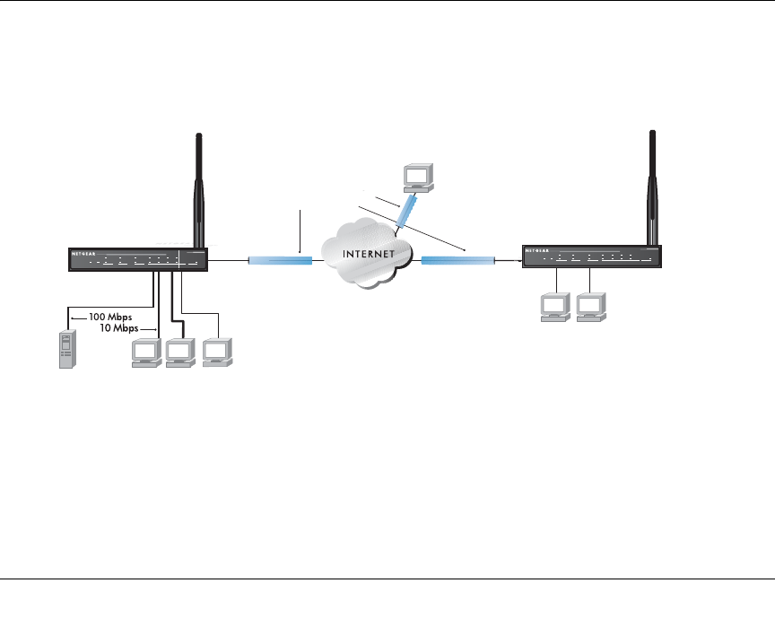
Figure 8-1: Secure access through FWG114P VPN routers
931WXQQHOV
HQFU\SWGDWD
7HOHFRPPXWHUZLWK
FOLHQWVRIWZDUH
+Á.?wjËoåÔ±¤¤~Ë8ÁjjÄÄËÁjÝ?Ê+ÁÍË.jÁÜjÁ
Á?aM?a # 8¤¤|+
3:5
02).4%2 -/$%- ).4%2.%4 ,/#!, 7,!.
7(67
$&7
$/(57
$&7
$/(57
/1.$&7
/1.$&7
+Á.?wjËoåÔ±¤¤~Ë8ÁjjÄÄËÁjÝ?Ê+ÁÍË.jÁÜjÁ
Á?aM?a # 8¤¤|+
3:5
02).4%2 -/$%- ).4%2.%4 ,/#!, 7,!.
7(67
$&7
$/(57
$&7
$/(57
/1.$&7
/1.$&7
#OMPUTERS
#OMPUTERS
3ERVER

Reference Manual for the ProSafe Wireless 802.11g Firewall/Print Server Model FWG114P
8-2 Virtual Private Networking
March 2004, 202-10027-01
Using Policies to Manage VPN Traffic
You create policy definitions to manage VPN traffic on the FWG114P. There are two kinds of
policies:
•IKE Policies: Define the authentication scheme and automatically generate the encryption
keys. As an alternative option, to further automate the process, you can create an IKE policy
which uses a trusted certificate authority to provide the authentication while the IKE policy
still handles the encryption.
•VPN Policies: Apply the IKE policy to specific traffic which requires a VPN tunnel. Or, you
can create a VPN policy which does not use an IKE policy but in which you manually enter all
the authentication and key parameters.
Since the VPN policies use the IKE policies, you define the IKE policy first. The FWG114P also
allows you to manually input the authentication scheme and encryption key values. In the case of
manual key management there will not be any IKE policies.
In order to establish secure communication over the Internet with the remote site you need to
configure matching VPN policies on both the local and remote FWG114P Wireless Firewall/Print
Servers. The outbound VPN policy on one end must match to the inbound VPN policy on other
end, and vice versa.
When the network traffic enters into the FWG114P from the LAN network interface, if there is no
VPN policy found for a type of network traffic, then that traffic passes through without any
change. However, if the traffic is selected by a VPN policy, then the IPSec authentication and
encryption rules will be applied to it as defined in the VPN policy.
By default, a new VPN policy is added with the least priority, that is, at the end of the VPN policy
table.
Using Automatic Key Management
The most common configuration scenarios will use IKE policies to automatically manage the
authentication and encryption keys. Based on the IKE policy, some parameters for the VPN tunnel
are generated automatically. The IKE protocols perform negotiations between the two VPN
endpoints to automatically generate required parameters.
Some organizations will use an IKE policy with a Certificate Authority (CA) to perform
authentication. Typically, CA authentication is used in large organizations which maintain their
own internal CA server. This requires that each VPN gateway has a certificate from the CA. Using
CAs reduces the amount of data entry required on each VPN endpoint.
Reference Manual for the ProSafe Wireless 802.11g Firewall/Print Server Model FWG114P
Virtual Private Networking 8-3
March 2004, 202-10027-01
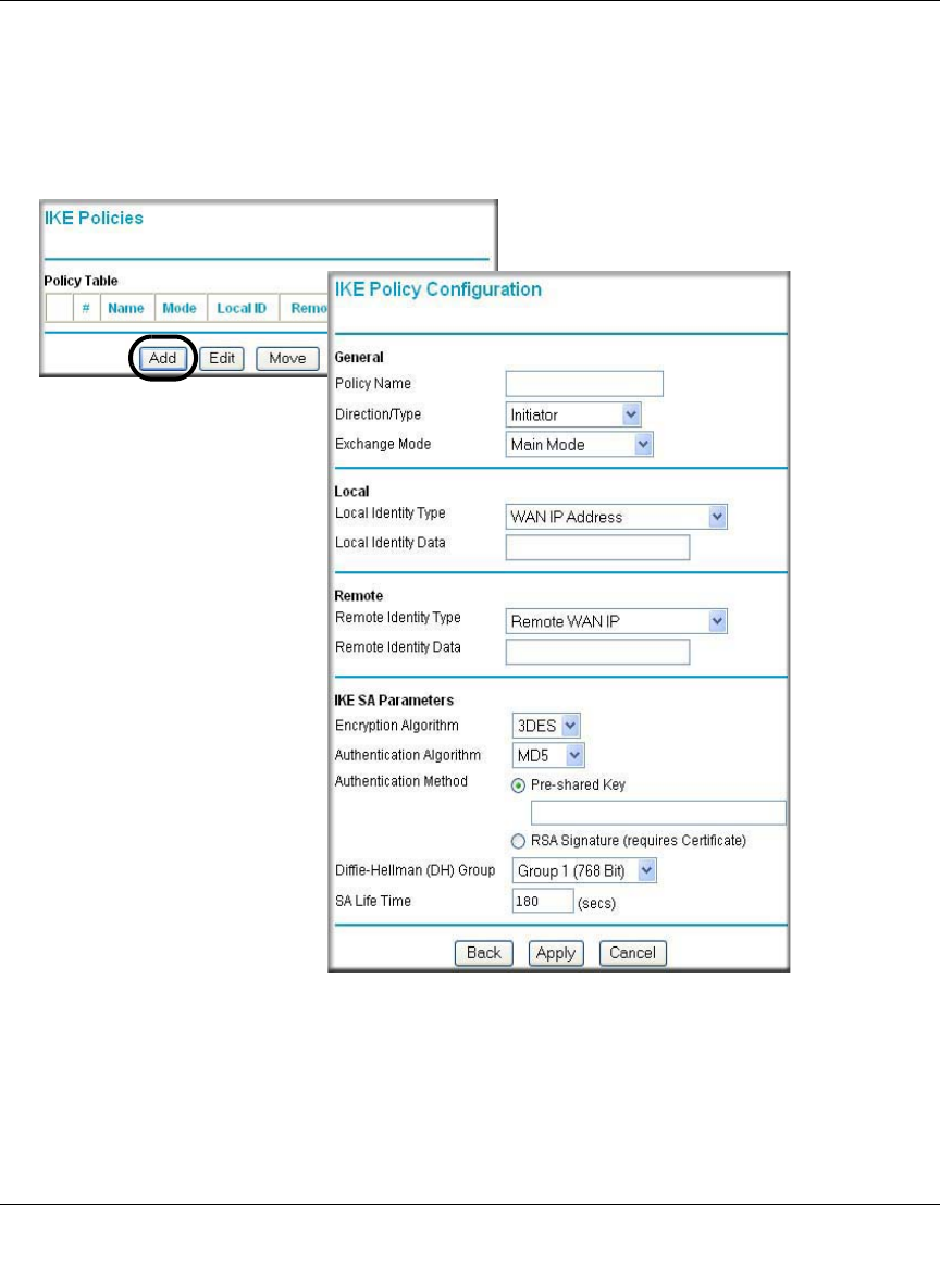
IKE Policies’ Automatic Key and Authentication Management
Click the IKE Policies link from the VPN section of the main menu, and then click the Add button
of the IKE Policies screen to display the IKE Policy Configuration menu shown in Figure 8-2.
Figure 8-2: IKE - Policy Configuration Menu

Reference Manual for the ProSafe Wireless 802.11g Firewall/Print Server Model FWG114P
8-4 Virtual Private Networking
March 2004, 202-10027-01
The IKE Policy Configuration fields are defined in the following table.
Table 8-1. IKE Policy Configuration Fields
Field Description
General These settings identify this policy and determine its major characteristics.
Policy Name The descriptive name of the IKE policy. Each policy should have a unique
policy name. This name is not supplied to the remote VPN endpoint. It is
only used to help you identify IKE policies.
Direction/Type This setting is used when determining if the IKE policy matches the current
traffic. The drop-down menu includes the following:
• Initiator – Outgoing connections are allowed, but incoming are blocked.
• Responder – Incoming connections are allowed, but outgoing are
blocked.
• Both Directions – Both outgoing and incoming connections are allowed.
• Remote Access – This is to allow only incoming client connections,
where the IP address of the remote client is unknown.
If Remote Access is selected, the “Exchange Mode” MUST be
“Aggressive,” and the ‘Identities’ below (both Local and Remote) MUST
be “Name.” On the matching VPN Policy, the IP address of the remote
VPN endpoint should be set to 0.0.0.0.
Exchange Mode Main Mode or Aggressive Mode. This setting must match the setting used
on the remote VPN endpoint.
• Main Mode is slower but more secure. Also, the “Identity” below must be
established by IP address.
• Aggressive Mode is faster but less secure. The “Identity” below can be by
name (host name, domain name, e-mail address, and so on) instead of
by IP address.
Local These parameters apply to the Local FWG114P Wireless Firewall/Print
Server.
Local Identity Type Use this field to identify the local FWG114P. You can choose one of the
following four options from the drop-down list:
• By its Internet (WAN) port IP address.
• By its Fully Qualified Domain Name (FQDN) -- your domain name.
• By a Fully Qualified User Name -- your name, E-mail address, or
other ID.
• By DER ASN.1 DN -- the binary DER encoding of your ASN.1 X.500
Distinguished Name.
Local Identity Data This field lets you identify the local FWG114P by name.

Reference Manual for the ProSafe Wireless 802.11g Firewall/Print Server Model FWG114P
Virtual Private Networking 8-5
March 2004, 202-10027-01
Remote These parameters apply to the target remote FWG114P, VPN gateway, or
VPN client.
Remote Identity Type Use this field to identify the remote FWG114P. You can choose one of the
following four options from the drop-down list:
• By its Internet (WAN) port IP address.
• By its Fully Qualified Domain Name (FQDN) — your domain name.
• By a Fully Qualified User Name — your name, e-mail address, or
other ID.
• By DER ASN.1 DN — the binary DER encoding of your ASN.1 X.500
Distinguished Name.
Remote Identity Data This field lets you identify the target remote FWG114P by name.
IKE SA Parameters These parameters determine the properties of the IKE Security
Association.
Encryption Algorithm Choose the encryption algorithm for this IKE policy:
• DES is the default.
• 3DES is more secure.
Authentication Algorithm If you enable Authentication Header (AH), this menu lets you to select from
these authentication algorithms:
• MD5 is the default.
• SHA-1 is more secure.
Authentication Method You may select Pre-Shared Key or RSA Signature.
Pre-Shared Key Specify the key according to the requirements of the Authentication
Algorithm you selected.
• For MD5, the key length should be 16 bytes.
• For SHA-1, the key length should be 20 bytes.
RSA Signature RSA Signature requires a certificate.
Diffie-Hellman (D-H) Group The DH Group setting determines the bit size used in the key exchange.
This must match the value used on the remote VPN gateway or client.
SA Life Time The amount of time in seconds before the Security Association expires;
over an hour (3600) is common.
Table 8-1. IKE Policy Configuration Fields
Field Description
Reference Manual for the ProSafe Wireless 802.11g Firewall/Print Server Model FWG114P
8-6 Virtual Private Networking
March 2004, 202-10027-01
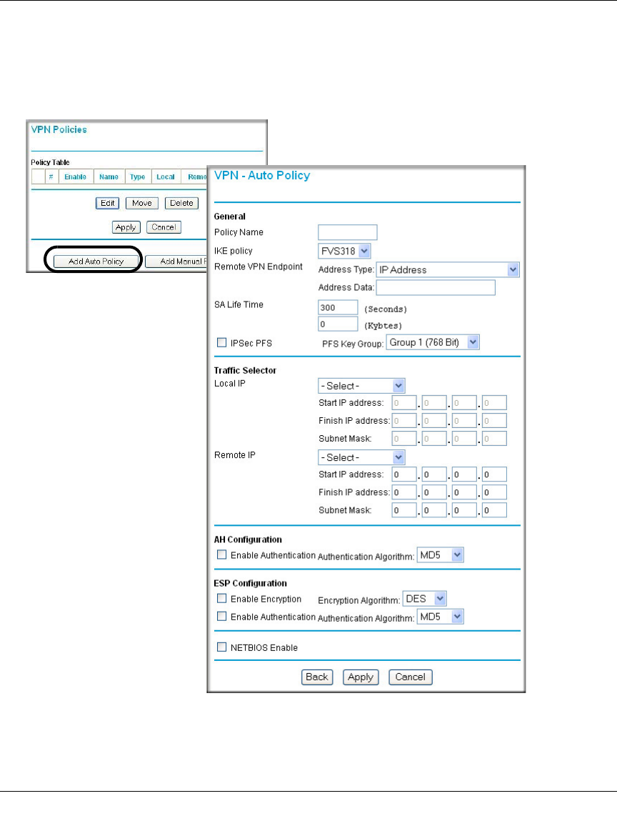
VPN Policy Configuration for Auto Key Negotiation
An already defined IKE policy is required for VPN - Auto Policy configuration. From the VPN
Policies section of the main menu, you can navigate to the VPN - Auto Policy configuration menu.
Figure 8-3: VPN - Auto Policy Menu
Reference Manual for the ProSafe Wireless 802.11g Firewall/Print Server Model FWG114P
Virtual Private Networking 8-7
March 2004, 202-10027-01
The VPN Auto Policy fields are defined in the following table.
Table 8-1. VPN Auto Policy Configuration Fields
Field Description
General These settings identify this policy and determine its major characteristics.
Policy Name The descriptive name of the VPN policy. Each policy should have a unique
policy name. This name is not supplied to the remote VPN endpoint. It is
only used to help you identify VPN policies.
IKE Policy The existing IKE policies are presented in a drop-down list.
Note: Create the IKE policy BEFORE creating a VPN - Auto policy.
Remote VPN Endpoint The address used to locate the remote VPN firewall or client to which you
wish to connect. The remote VPN endpoint must have this FWG114P’s
Local IP values entered as its “Remote VPN Endpoint.”
• By its Fully Qualified Domain Name (FQDN) — your domain name.
• By its IP Address.
Address Type The address type used to locate the remote VPN firewall or client to which
you wish to connect.
• By its Fully Qualified Domain Name (FQDN) — your domain name.
• By its IP Address.
Address Data The address used to locate the remote VPN firewall or client to which you
wish to connect. The remote VPN endpoint must have this FWG114P’s
Local Identity Data entered as its “Remote VPN Endpoint.”
• By its Fully Qualified Domain Name (FQDN) — your domain name.
• By its IP Address.
SA Life Time The duration of the Security Association before it expires.
• Seconds - the amount of time before the SA expires. Over an hour is
common (3600).
• Kbytes - the amount of traffic before the SA expires.
One of these can be set without setting the other.
IPSec PFS If enabled, security is enhanced by ensuring that the key is changed at
regular intervals. Also, even if one key is broken, subsequent keys are no
easier to break. Each key has no relationship to the previous key.
PFS Key Group If PFS is enabled, this setting determines the DH group bit size used in the
key exchange. This must match the value used on the remote gateway.

Reference Manual for the ProSafe Wireless 802.11g Firewall/Print Server Model FWG114P
8-8 Virtual Private Networking
March 2004, 202-10027-01
Traffic Selector These settings determine if and when a VPN tunnel will be established. If
network traffic meets all criteria, then a VPN tunnel will be created.
Local IP The drop-down menu allows you to configure the source IP address of the
outbound network traffic for which this VPN policy will provide security.
Usually, this address will be from your network address space. The
choices are:
• Default: ANY for all valid IP addresses in the Internet address space
Note: Selecting ANY means all traffic goes through the IPSec tunnel
and prevents access to the Internet.
• Single IP Address
• Range of IP Addresses
• Subnet Address
Remote IP The drop-down menu allows you to configure the destination IP address of
the outbound network traffic for which this VPN policy will provide security.
Usually, this address will be from the remote site's corporate network
address space. The choices are:
• ANY for all valid IP addresses in the Internet address space
Note: Selecting ANY means all traffic goes through the IPSec tunnel
and prevents access to the Internet.
• Single IP Address
• Range of IP Addresses
• Subnet Address
Authenticating Header (AH)
Configuration AH specifies the authentication protocol for the VPN header. These
settings must match the remote VPN endpoint.
Enable Authentication Use this checkbox to enable or disable AH for this VPN policy.
Authentication
Algorithm
If you enable AH, then select the authentication algorithm:
• MD5 is the default.
• SHA1 is more secure.
Encapsulated Security
Payload (ESP) Configuration ESP provides security for the payload (data) sent through the VPN tunnel.
Generally, you will want to enable both Encryption and Authentication.
Two ESP modes are available:
• Plain ESP encryption
• ESP encryption with authentication
These settings must match the remote VPN endpoint.
Table 8-1. VPN Auto Policy Configuration Fields
Field Description
Reference Manual for the ProSafe Wireless 802.11g Firewall/Print Server Model FWG114P
Virtual Private Networking 8-9
March 2004, 202-10027-01
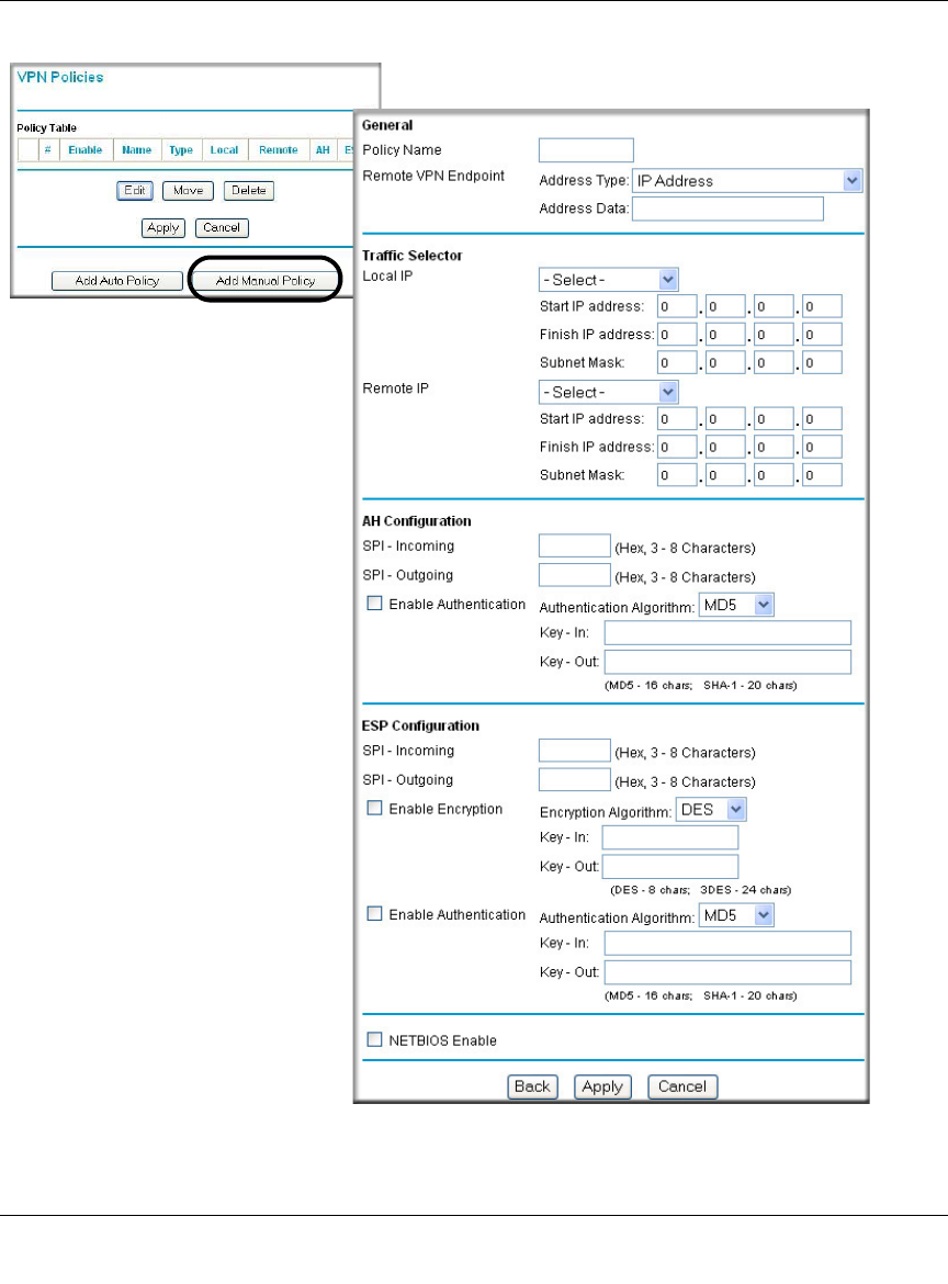
VPN Policy Configuration for Manual Key Exchange
With Manual Key Management, you will not use an IKE policy. You must manually type in all the
required key information. Click the VPN Policies link from the VPN section of the main menu to
display the menu shown below.
Enable Encryption Use this checkbox to enable or disable ESP Encryption.
Encryption
Algorithm
If you enable ESP encryption, then select the encryption algorithm:
• DES is the default.
• 3DES is more secure.
Enable Authentication Use this checkbox to enable or disable ESP transform for this VPN policy.
You can also select the ESP mode with this menu.
Two ESP modes are available:
•Plain ESP
• ESP with authentication
Authentication
Algorithm
If you enable AH, then use this menu to select which authentication
algorithm will be employed.
The choices are:
• MD5 is the default.
• SHA1 is more secure.
NETBIOS Enable Check this if you wish NETBIOS traffic to be forwarded over the VPN
tunnel. The NETBIOS protocol is used by Microsoft Networking for such
features as Network Neighborhood.
Table 8-1. VPN Auto Policy Configuration Fields
Field Description
Reference Manual for the ProSafe Wireless 802.11g Firewall/Print Server Model FWG114P
8-10 Virtual Private Networking
March 2004, 202-10027-01
Figure 8-4: VPN - Manual Policy Menu

Reference Manual for the ProSafe Wireless 802.11g Firewall/Print Server Model FWG114P
Virtual Private Networking 8-11
March 2004, 202-10027-01
The VPN Manual Policy fields are defined in the following table.
Table 8-1. VPN Manual Policy Configuration Fields
Field Description
General These settings identify this policy and determine its major characteristics.
Policy Name The name of the VPN policy. Each policy should have a unique policy
name. This name is not supplied to the remote VPN Endpoint. It is used to
help you identify VPN policies.
Remote VPN Endpoint The WAN Internet IP address of the remote VPN firewall or client to which
you wish to connect. The remote VPN endpoint must have this
FWG114P’s WAN Internet IP address entered as its “Remote VPN
Endpoint.”
Traffic Selector These settings determine if and when a VPN tunnel will be established. If
network traffic meets all criteria, then a VPN tunnel will be created.
Local IP The drop down menu allows you to configure the source IP address of the
outbound network traffic for which this VPN policy will provide security.
Usually, this address will be from your network address space. The
choices are:
• ANY for all valid IP addresses in the Internet address space
Note: Selecting ANY means all traffic goes through the IPSec tunnel
and prevents access to the Internet.
• Single IP Address
• Range of IP Addresses
• Subnet Address
Remote IP The drop down menu allows you to configure the destination IP address of
the outbound network traffic for which this VPN policy will provide security.
Usually, this address will be from the remote site's corporate network
address space. The choices are:
• ANY for all valid IP addresses in the Internet address space
Note: Selecting ANY means all traffic goes through the IPSec tunnel
and prevents access to the Internet.
• Single IP Address
• Range of IP Addresses
• Subnet Address

Reference Manual for the ProSafe Wireless 802.11g Firewall/Print Server Model FWG114P
8-12 Virtual Private Networking
March 2004, 202-10027-01
Authenticating Header (AH)
Configuration AH specifies the authentication protocol for the VPN header. These
settings must match the remote VPN endpoint.
Note: The "Incoming" settings here must match the "Outgoing" settings on
the remote VPN endpoint, and the "Outgoing" settings here must match
the "Incoming" settings on the remote VPN endpoint.
SPI - Incoming Enter a Hex value (3 - 8 chars). Any value is acceptable, provided the
remote VPN endpoint has the same value in its "Outgoing SPI" field.
SPI - Outgoing Enter a Hex value (3 - 8 chars). Any value is acceptable, provided the
remote VPN endpoint has the same value in its "Incoming SPI" field.
Enable Authentication Use this checkbox to enable or disable AH. Authentication is often not
used. In this case, leave the checkbox unchecked.
Authentication
Algorithm
If you enable AH, then select the authentication algorithm:
• MD5 is the default.
• SHA1 is more secure.
Enter the keys in the fields provided. For MD5, the keys should be 16
characters. For SHA-1, the keys should be 20 characters.
Key - In Enter the keys.
• For MD5, the keys should be 16 characters.
• For SHA-1, the keys should be 20 characters.
Any value is acceptable, provided the remote VPN endpoint has the same
value in its Authentication Algorithm "Key - Out" field.
Key - Out Enter the keys in the fields provided.
• For MD5, the keys should be 16 characters.
• For SHA-1, the keys should be 20 characters.
Any value is acceptable, provided the remote VPN endpoint has the same
value in its Authentication Algorithm "Key - In" field.
Encapsulated Security
Payload (ESP) Configuration ESP provides security for the payload (data) sent through the VPN tunnel.
Generally, you will want to enable both encryption and authentication
when you use ESP. Two ESP modes are available:
• Plain ESP encryption
• ESP encryption with authentication
These settings must match the remote VPN endpoint.
SPI - Incoming Enter a Hex value (3 - 8 chars). Any value is acceptable, provided the
remote VPN endpoint has the same value in its "Outgoing SPI" field.
Table 8-1. VPN Manual Policy Configuration Fields
Field Description

Reference Manual for the ProSafe Wireless 802.11g Firewall/Print Server Model FWG114P
Virtual Private Networking 8-13
March 2004, 202-10027-01
SPI - Outgoing Enter a Hex value (3 - 8 chars). Any value is acceptable, provided the
remote VPN endpoint has the same value in its "Incoming SPI" field.
Enable Encryption Use this checkbox to enable or disable ESP Encryption.
Encryption
Algorithm
If you enable ESP Encryption, then select the Encryption Algorithm:
• DES is the default.
• 3DES is more secure.
Key - In Enter the key in the fields provided.
• For DES, the key should be 8 characters.
• For 3DES, the key should be 24 characters.
Any value is acceptable, provided the remote VPN endpoint has the same
value in its Encryption Algorithm "Key - Out" field.
Key - Out Enter the key in the fields provided.
• For DES, the key should be 8 characters.
• For 3DES, the key should be 24 characters.
Any value is acceptable, provided the remote VPN endpoint has the same
value in its Encryption Algorithm "Key - In" field.
Enable Authentication Use this checkbox to enable or disable ESP authentication for this VPN
policy.
Authentication
Algorithm
If you enable authentication, then use this menu to select the algorithm:
• MD5 is the default.
• SHA1 is more secure.
Key - In Enter the key.
• For MD5, the key should be 16 characters.
• For SHA-1, the key should be 20 characters.
Any value is acceptable, provided the remote VPN endpoint has the same
value in its Authentication Algorithm "Key - Out" field.
Table 8-1. VPN Manual Policy Configuration Fields
Field Description
Reference Manual for the ProSafe Wireless 802.11g Firewall/Print Server Model FWG114P
8-14 Virtual Private Networking
March 2004, 202-10027-01
Using Digital Certificates for IKE Auto-Policy Authentication
Digital certificates are strings generated using encryption and authentication schemes which
cannot be duplicated by anyone without access to the different values used in the production of the
string. They are issued by Certification Authorities (CAs) to authenticate a person or a workstation
uniquely. The CAs are authorized to issue these certificates by Policy Certification Authorities
(PCAs), who are in turn certified by the Internet Policy Registration Authority (IPRA). The
FWG114P is able to use certificates to authenticate users at the end points during the IKE key
exchange process.
The certificates can be obtained from a certificate server an organization might maintain internally
or from the established public CAs. The certificates are produced by providing the particulars of
the user being identified to the CA. The information provided may include the user's name, e-mail
ID, domain name, and so on.
Each CA has its own certificate. The certificates of a CA are added to the FWG114P and can then
be used to form IKE policies for the user. Once a CA certificate is added to the FWG114P and a
certificate is created for a user, the corresponding IKE policy is added to the FWG114P. Whenever
the user tries to send traffic through the FWG114P, the certificates are used in place of pre-shared
keys during initial key exchange as the authentication and key generation mechanism. Once the
keys are established and the tunnel is set up the connection proceeds according to the VPN policy.
Certificate Revocation List (CRL)
Each Certification Authority (CA) maintains a list of the revoked certificates. The list of these
revoked certificates is known as the Certificate Revocation List (CRL).
Key - Out Enter the key in the fields provided.
• For MD5, the key should be 16 characters.
• For SHA-1, the key should be 20 characters.
Any value is acceptable, provided the remote VPN endpoint has the same
value in its Authentication Algorithm "Key - In" field.
NETBIOS Enable Check this if you wish NETBIOS traffic to be forwarded over the VPN
tunnel. The NETBIOS protocol is used by Microsoft Networking for such
features as Network Neighborhood.
Table 8-1. VPN Manual Policy Configuration Fields
Field Description
Reference Manual for the ProSafe Wireless 802.11g Firewall/Print Server Model FWG114P
Virtual Private Networking 8-15
March 2004, 202-10027-01
Whenever an IKE policy receives the certificate from a peer, it checks for this certificate in the
CRL on the FWG114P obtained from the corresponding CA. If the certificate is not present in the
CRL it means that the certificate is not revoked. IKE can then use this certificate for
authentication. If the certificate is present in the CRL it means that the certificate is revoked, and
the IKE will not authenticate the client.
You must manually update the FWG114P CRL regularly in order for the CA-based authentication
process to remain valid.
Walk-Through of Configuration Scenarios on the FWG114P
There are a variety of configurations you might implement with the FWG114P. The scenarios
listed below illustrate typical configurations you might use in your organization.
In order to help make it easier to set up an IPsec system, the following two scenarios are provided.
These scenarios were developed by the VPN Consortium (http://www.vpnc.org). The goal is to
make it easier to get the systems from different vendors to interoperate. NETGEAR is providing
you with both of these scenarios in the following two formats:
• VPN Consortium Scenarios without Any Product Implementation Details as presented in
“VPNC Scenario 1: Gateway to Gateway with Preshared Secrets” on page 8-19 and “VPNC
Scenario 2: Gateway-to-Gateway with Certificates” on page 8-25.
• VPN Consortium Scenarios Based on the FWG114P User Interface as presented in
“Scenario 1: FWG114P to FWG114P with Preshared Secrets” on page 8-20 and “Scenario 2:
FWG114P to FWG114P with Certificates” on page 8-26.
The purpose of providing these two versions of the same scenarios is to help you determine where
the two vendors use different vocabulary. Seeing the examples presented in these different ways
will reveal how systems from different vendors do the same thing.
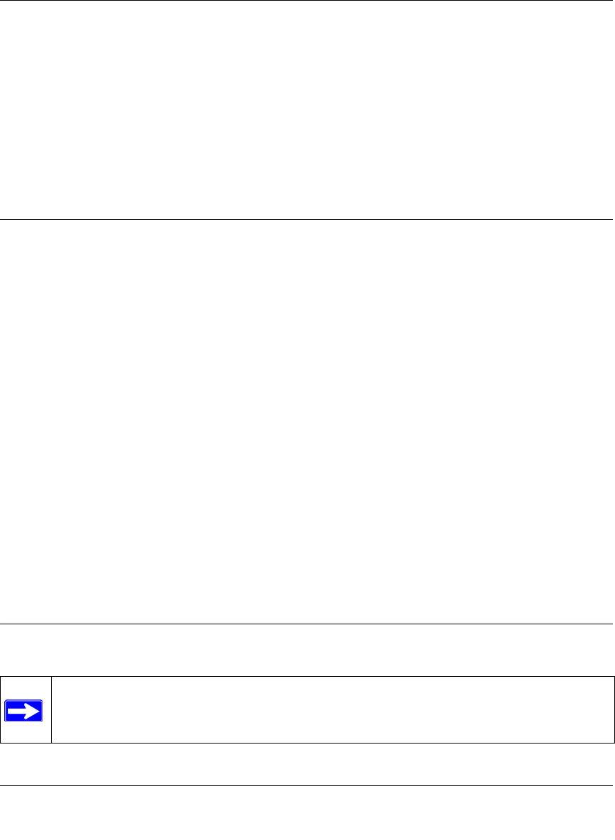
How to Use the VPN Wizard to Configure a VPN Tunnel
Note: If you have turned NAT off, before configuring VPN IPSec tunnels you must first
open UDP port 500 for inbound traffic as explained in “Example: Port Forwarding for
VPN Tunnels when NAT is Off” on page 6-8.
Reference Manual for the ProSafe Wireless 802.11g Firewall/Print Server Model FWG114P
8-16 Virtual Private Networking
March 2004, 202-10027-01
Follow this procedure to configure a VPN tunnel using the VPN Wizard.
Note: The LAN IP address ranges of each VPN endpoint must be different. The connection will
fail if both are using the NETGEAR default address range of 192.168.0.x.
1. Log in to the FVS318 on LAN A at its default LAN address of http://192.168.0.1 with its
default user name of admin and password of password. Click the VPN Wizard link in the
main menu to display this screen. Click Next to proceed.
Figure 8-5: VPN Wizard Start Screen
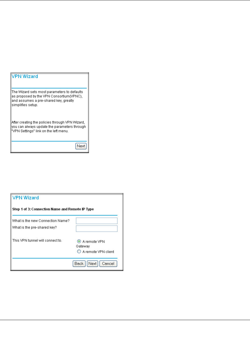
2. Fill in the Connection Name, pre-shared key, and select the type of target end point, and click
Next to proceed.
Figure 8-6: Connection Name and Remote IP Type
Reference Manual for the ProSafe Wireless 802.11g Firewall/Print Server Model FWG114P
Virtual Private Networking 8-17
March 2004, 202-10027-01
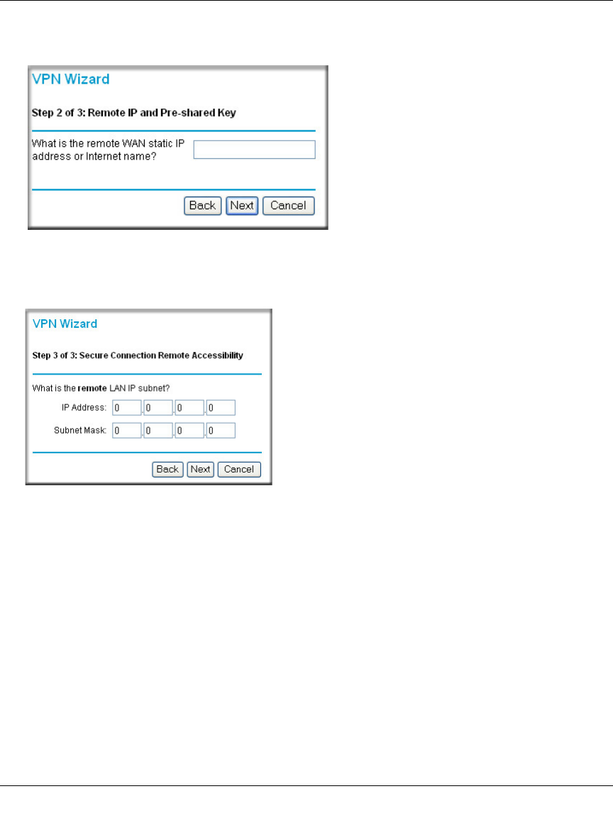
3. Fill in the IP Address or FQDN for the target VPN endpoint WAN connection and click Next.
Figure 8-7: Remote IP
4. Identify the IP addresses at the target endpoint which can use this tunnel, and click Next.
Figure 8-8: Secure Connection Remote Accessibility
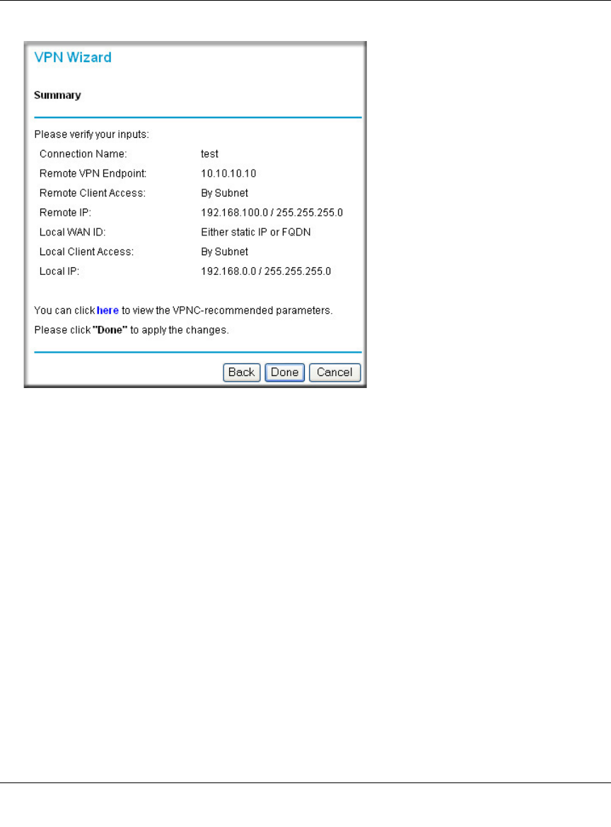
The Summary screen below displays.
Reference Manual for the ProSafe Wireless 802.11g Firewall/Print Server Model FWG114P
8-18 Virtual Private Networking
March 2004, 202-10027-01
Figure 8-9: VPN Wizard Summary
To view the VPNC recommended authentication and encryption Phase 1 and Phase 2 settings
the VPN Wizard used, click the “here” link.
5. Click Done to complete the configuration procedure. The VPN Settings menu displays
showing that the new tunnel is enabled
To view or modify the tunnel settings, select the radio button next to the tunnel entry and click
Edit.
Reference Manual for the ProSafe Wireless 802.11g Firewall/Print Server Model FWG114P
Virtual Private Networking 8-19
March 2004, 202-10027-01
VPNC Scenario 1: Gateway to Gateway with Preshared Secrets
The following is a typical gateway-to-gateway VPN that uses a preshared secret for authentication.
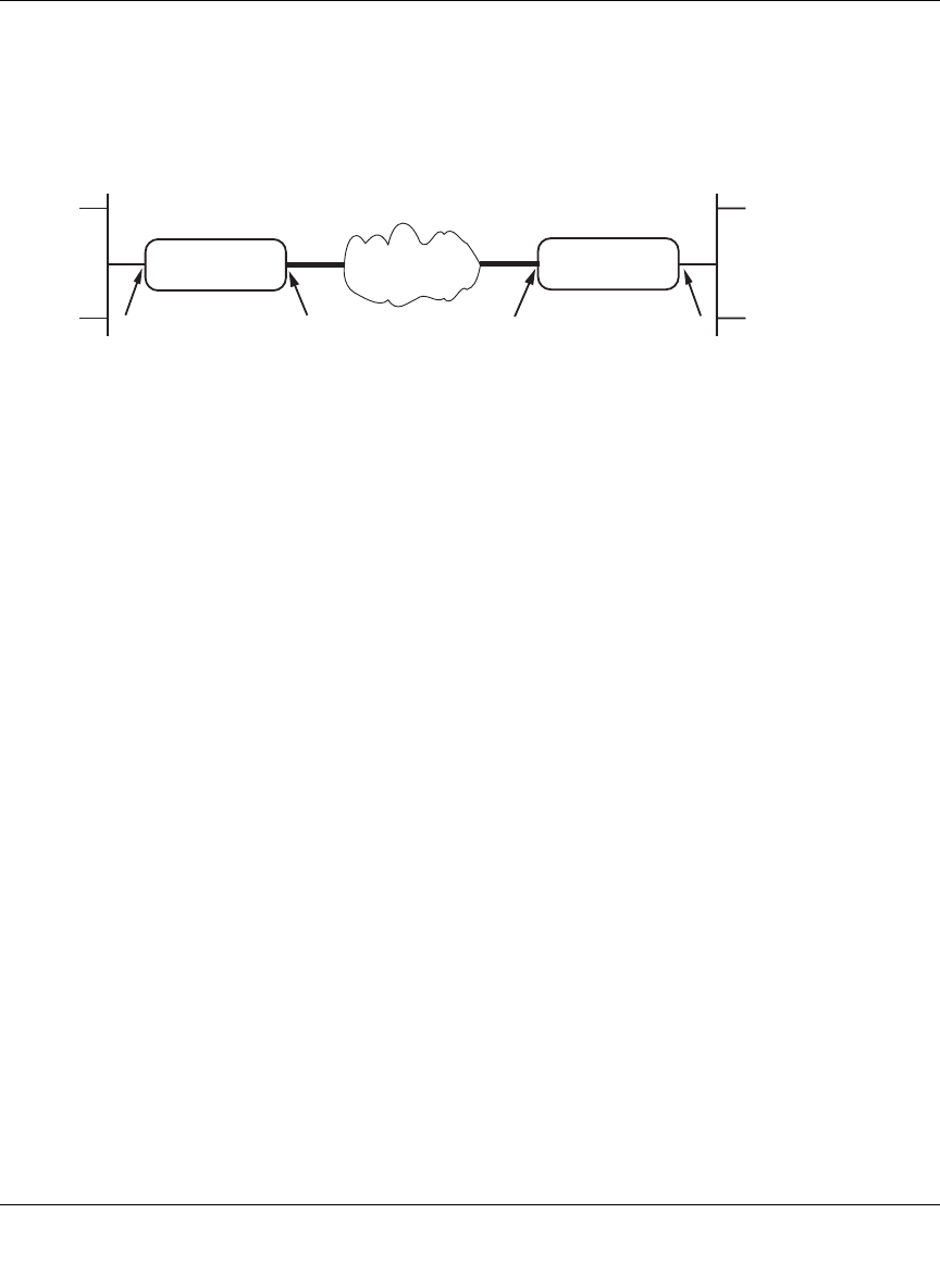
Figure 8-10: VPN Consortium Scenario 1
Gateway A connects the internal LAN 10.5.6.0/24 to the Internet. Gateway A's LAN interface has
the address 10.5.6.1, and its WAN (Internet) interface has the address 14.15.16.17.
Gateway B connects the internal LAN 172.23.9.0/24 to the Internet. Gateway B's WAN (Internet)
interface has the address 22.23.24.25. Gateway B's LAN interface address, 172.23.9.1, can be used
for testing IPsec but is not needed for configuring Gateway A.
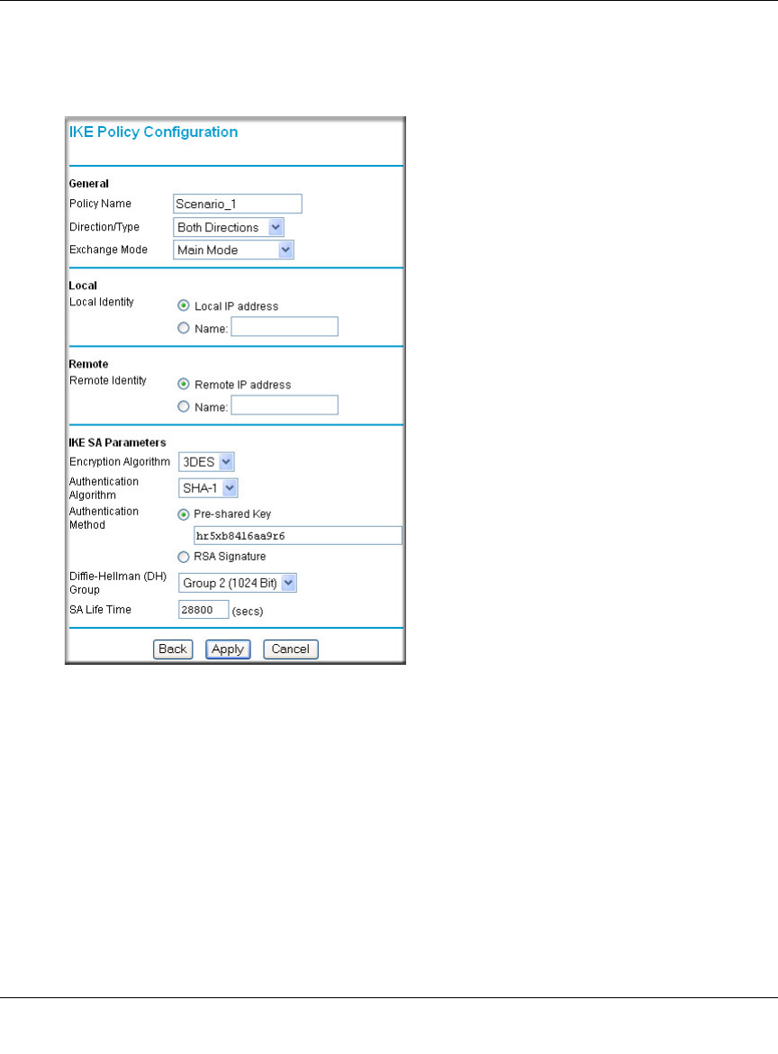
The IKE Phase 1 parameters used in Scenario 1 are:
•Main mode
• TripleDES
• SHA-1
• MODP group 2 (1024 bits)
• pre-shared secret of "hr5xb84l6aa9r6"
• SA lifetime of 28800 seconds (eight hours) with no kbytes rekeying
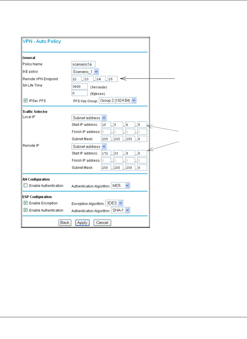
The IKE Phase 2 parameters used in Scenario 1 are:
• TripleDES
• SHA-1
• ESP tunnel mode
• MODP group 2 (1024 bits)
• Perfect forward secrecy for rekeying
• SA lifetime of 3600 seconds (one hour) with no kbytes rekeying
• Selectors for all IP protocols, all ports, between 10.5.6.0/24 and 172.23.9.0/24, using IPv4
subnets
10.5.6.0/24
10.5.6.1
Gateway A
14.15.16.17 22.23.24.25
172.23.9.0/24
Internet Gateway B
172.23.9.1
Reference Manual for the ProSafe Wireless 802.11g Firewall/Print Server Model FWG114P
8-20 Virtual Private Networking
March 2004, 202-10027-01
Scenario 1: FWG114P to FWG114P with Preshared Secrets
Note: This scenario assumes all ports are open on the FWG114P. You can verify this by reviewing
the security settings as seen in the “Rules menu” on page 6-5.
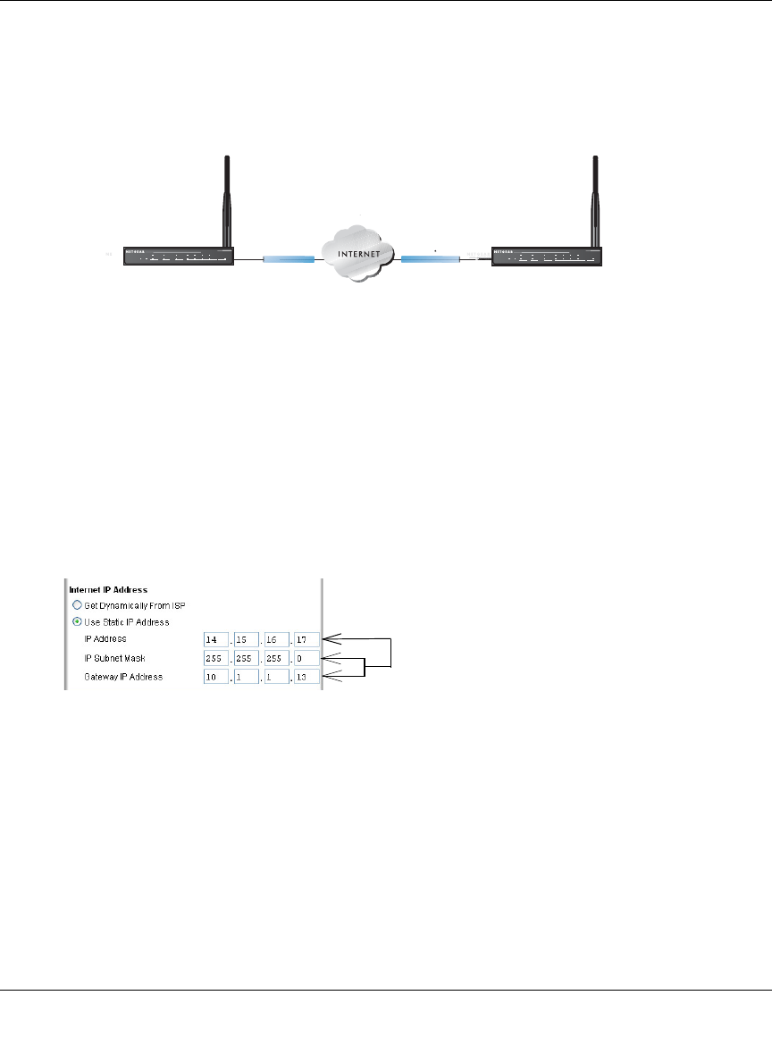
Figure 8-11: LAN to LAN VPN access from an FWG114P to an FWG114P
Use this scenario illustration and configuration screens as a model to build your configuration.
1. Log in to the FWG114P labeled Gateway A as in the illustration.
Log in at the default address of http://192.168.0.1 with the default user name of admin and
default password of password, or using whatever password and LAN address you have
chosen.
2. Configure the WAN (Internet) and LAN IP addresses of the FWG114P.
a. From the main menu Setup section, click on the Basic Setup link.
Figure 8-12: FWG114P Internet IP Address menu
b. Configure the WAN Internet Address according to the settings above and click Apply to
save your settings. For more information on configuring the WAN IP settings in the Basic
Setup topics, please see “Manually Configuring Your Internet Connection” on page 3-17.
*DWHZD\%
6FHQDULR
:$1,3 :$1,3
/$1,3 /$1,3
*DWHZD\$
+Á.?wjËoåÔ±¤¤~Ë8ÁjjÄÄËÁjÝ?Ê+ÁÍË.jÁÜjÁ
Á?aM?a # 8¤¤|+
3:5
02).4%2 -/$%- ).4%2.%4 ,/#!, 7,!.
7(67
$&7
$/(57
$&7
$/(57
/1.$&7
/1.$&7
+Á.?wjËoåÔ±¤¤~Ë8ÁjjÄÄËÁjÝ?Ê+ÁÍË.jÁÜjÁ
Á?aM?a # 8¤¤|+
3:5
02).4%2 -/$%- ).4%2.%4 ,/#!, 7,!.
7(67
$&7
$/(57
$&7
$/(57
/1.$&7
/1.$&7
WAN IP
addresses
ISP provides
these addresses
Reference Manual for the ProSafe Wireless 802.11g Firewall/Print Server Model FWG114P
Virtual Private Networking 8-21
March 2004, 202-10027-01
c. From the main menu Advanced section, click on the LAN IP Setup link.
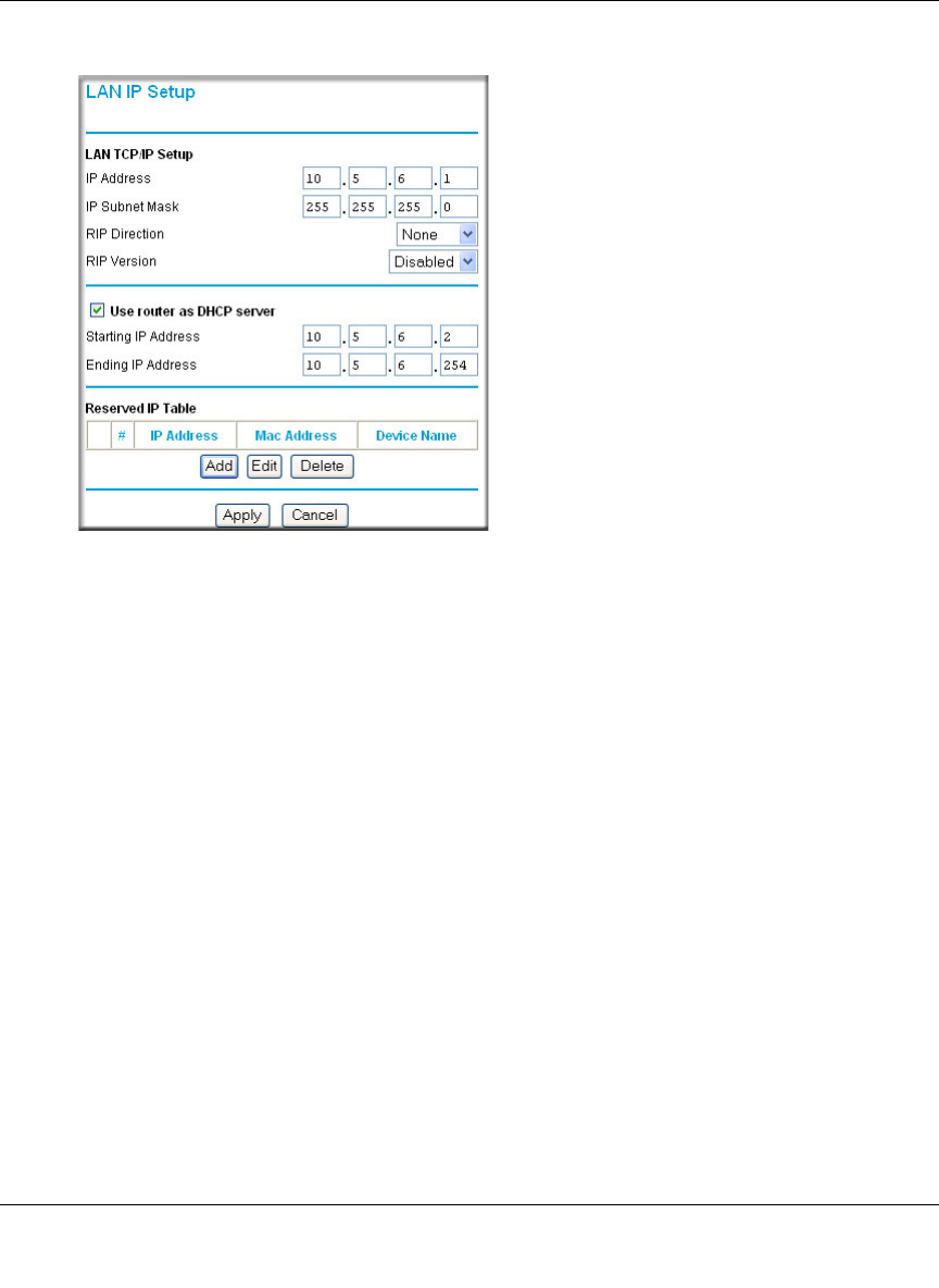
Figure 8-13: LAN IP configuration menu
d. Configure the LAN IP address according to the settings above and click Apply to save
your settings. For more information on LAN TCP/IP setup topics, please see “Using the
LAN IP Setup Options” on page 10-5.
Note: After you click Apply to change the LAN IP address settings, your workstation will
be disconnected from the FWG114P. You will have to log on with http://10.5.6.1, which is
now the address you use to connect to the built-in web-based configuration manager of the
FWG114P.
Reference Manual for the ProSafe Wireless 802.11g Firewall/Print Server Model FWG114P
8-22 Virtual Private Networking
March 2004, 202-10027-01
3. Set up the IKE Policy illustrated below on the FWG114P.
a. From the main menu VPN section, click on the IKE Policies link, and then click the Add
button to display the screen below.
Figure 8-14: Scenario 1 IKE Policy
b. Configure the IKE Policy according to the settings in the illustration above and click
Apply to save your settings. For more information on IKE Policy topics, please see “IKE
Policies’ Automatic Key and Authentication Management” on page 8-3.
Reference Manual for the ProSafe Wireless 802.11g Firewall/Print Server Model FWG114P
Virtual Private Networking 8-23
March 2004, 202-10027-01
4. Set up the FWG114P VPN -Auto Policy illustrated below.
a. From the main menu VPN section, click on the VPN Policies link, and then click on the
Add Auto Policy button.
Figure 8-15: Scenario 1 VPN - Auto Policy
b. Configure the IKE Policy according to the settings in the illustration above and click
Apply to save your settings. For more information on IKE Policy topics, please see “IKE
Policies’ Automatic Key and Authentication Management” on page 8-3.
Note: Selecting ANY for the Traffic Selectors means all traffic goes through the IPSec
tunnel and prevents access to the Internet.
5. After applying these changes, all traffic from the range of LAN IP addresses specified on
FWG114P A and FWG114P B will flow over a secure VPN tunnel.
WAN IP
address
LAN IP
addresses

Reference Manual for the ProSafe Wireless 802.11g Firewall/Print Server Model FWG114P
8-24 Virtual Private Networking
March 2004, 202-10027-01
How to Check VPN Connections
You can test connectivity and view VPN status information on the FWG114P.
1. To test connectivity between the Gateway A FWG114P LAN and the Gateway B LAN, follow
these steps:
a. Using our example, from a PC attached to the FWG114P on LAN A, on a Windows PC
click the Start button on the taskbar and then click Run.
b. Enter ping -t 172.23.9.1, and then click OK.
c. This will cause a continuous ping to be sent to the LAN interface of Gateway B. After
between several seconds and two minutes, the ping response should change from “timed
out” to “reply.”
d. At this point the connection is established.
2. To test connectivity between the FWG114P Gateway A and Gateway B WAN ports, follow
these steps:
a. Using our example, log in to the FWG114P on LAN A, go to the main menu Maintenance
section and click the Diagnostics link.
b. To test connectivity to the WAN port of Gateway B, enter 22.23.24.25, and then click
Ping.
c. This will cause a ping to be sent to the WAN interface of Gateway B. After between
several seconds and two minutes, the ping response should change from “timed out” to
“reply.” You may have to run this test several times before you get the “reply” message
back from the target FWG114P.
d. At this point the connection is established.
Note: If you want to ping the FWG114P as a test of network connectivity, be sure the
FWG114P is configured to respond to a ping on the Internet WAN port by checking the
checkbox seen in “Rules menu” on page 6-5. However, to preserve a high degree of security,
you should turn off this feature when you are finished with testing.
3. To view the FWG114P event log and status of Security Associations, follow these steps:
a. Go to the FWG114P main menu VPN section and click the VPN Status link.
b. The log screen will display a history of the VPN connections, and the IPSec SA and IKE
SA tables will report the status and data transmission statistics of the VPN tunnels for each
policy.

Reference Manual for the ProSafe Wireless 802.11g Firewall/Print Server Model FWG114P
Virtual Private Networking 8-25
March 2004, 202-10027-01
VPNC Scenario 2: Gateway-to-Gateway with Certificates
The following is a typical gateway-to-gateway VPN that uses PKIX certificates for authentication.
Figure 8-16: VPN Consortium Scenario 2
Gateway A connects the internal LAN 10.5.6.0/24 to the Internet. Gateway A's LAN interface has
the address 10.5.6.1, and its WAN (Internet) interface has the address 14.15.16.17.
Gateway B connects the internal LAN 172.23.9.0/24 to the Internet. Gateway B's WAN (Internet)
interface has the address 22.23.24.25. Gateway B's LAN interface address, 172.23.9.1, can be used
for testing IPsec but is not needed for configuring Gateway A.
The IKE Phase 1 parameters used in Scenario 2 are:
•Main mode
• TripleDES
• SHA-1
• MODP group 2 (1024 bits)
• Authentication with signatures authenticated by PKIX certificates; both Gateway A and
Gateway B have end-entity certificates that chain to a root authority called "Trusted Root CA."
• SA lifetime of 28800 seconds (eight hours) with no kbytes rekeying
The IKE Phase 2 parameters used in Scenario 2 are:
• TripleDES
• SHA-1
• ESP tunnel mode
• MODP group 2 (1024 bits)
• Perfect forward secrecy for rekeying
• SA lifetime of 3600 seconds (one hour) with no kbytes rekeying
10.5.6.0/24
10.5.6.1
Gateway A
14.15.16.17 22.23.24.25
172.23.9.0/24
Internet Gateway B
172.23.9.1

Reference Manual for the ProSafe Wireless 802.11g Firewall/Print Server Model FWG114P
8-26 Virtual Private Networking
March 2004, 202-10027-01
• Selectors for all IP protocols, all ports, between 10.5.6.0/24 and 172.23.9.0/24, using IPv4
subnets
Scenario 2: FWG114P to FWG114P with Certificates
The following is a typical gateway-to-gateway VPN that uses Public Key Infrastructure x.509
(PKIX) certificates for authentication. The network setup is identical to the one given in scenario
1. The IKE Phase 1 and Phase 2 parameters are identical to the ones given in scenario 1, with the
exception that the identification is done with signatures authenticated by PKIX certificates.
Note: Before completing this configuration scenario, make sure the correct Time Zone is set on the
FWG114P. For instructions on this topic, please see, “Setting the Time Zone” on page 6-13.
1. Obtain a root certificate.
a. Obtain the root certificate (which includes the public key) from a Certificate Authority
(CA)
Note: The procedure for obtaining certificates differs from a CA like Verisign and a CA,
such as a Windows 2000 certificate server, which an organization operates for providing
certificates for its members. For example, an administrator of a Windows 2000 certificate
server might provide it to you via e-mail.
b. Save the certificate as a text file called trust.txt.
2. Install the trusted CA certificate for the Trusted Root CA.
a. Log in to the FWG114P.
b. From the main menu VPN section, click on the CA’s link.
c. Click Add to add a CA.
d. Click Browse to locate the trust.txt file.
e. Click Upload.
3. Create a certificate request for the FWG114P.
a. From the main menu VPN section, click the Certificates link.
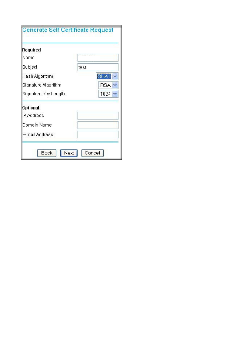
Reference Manual for the ProSafe Wireless 802.11g Firewall/Print Server Model FWG114P
Virtual Private Networking 8-27
March 2004, 202-10027-01
b. Click the Generate Request button to display the screen illustrated in Figure 8-17 below.
.
Figure 8-17: Generate Self Certificate Request menu
c. Fill in the fields on the Add Self Certificate screen.
•Required
– Name. Enter a name to identify this certificate.
– Subject. This is the name which other organizations will see as the holder (owner)
of this certificate. This should be your registered business name or official
company name. Generally, all certificates should have the same value in the
Subject field.
– Hash Algorithm. Select the desired option: MD5 or SHA1.
– Signature Algorithm. Select the desired option: DSS or RSA.
– Signature Key Length. Select the desired option: 512, 1024, or 2048.
• Optional
– IP Address. If you use “IP type” in the IKE policy, you should input the IP
Address here. Otherwise, you should leave this blank.
– Domain Name. If you have a domain name, you can enter it here. Otherwise, you
should leave this blank.
FWG114P
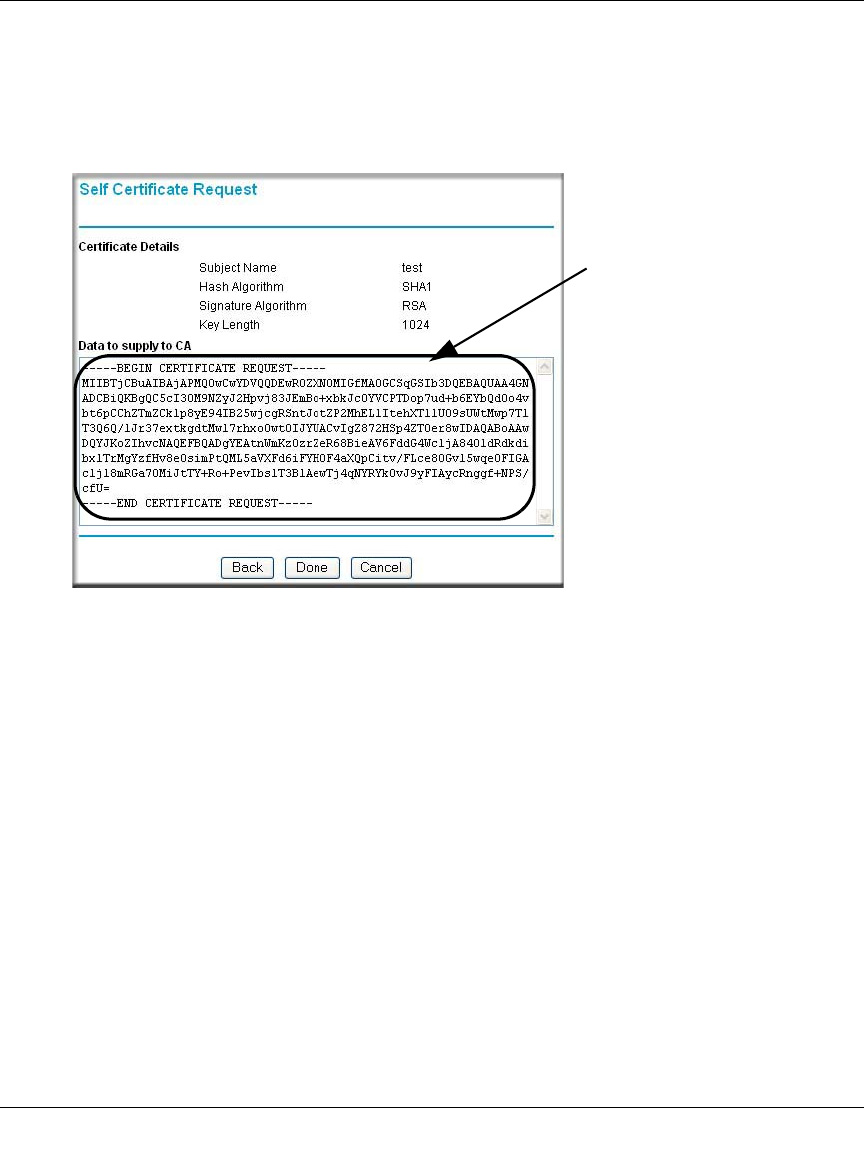
Reference Manual for the ProSafe Wireless 802.11g Firewall/Print Server Model FWG114P
8-28 Virtual Private Networking
March 2004, 202-10027-01
– E-mail Address. You can enter your e-mail address here.
d. Click the Next button to continue. The FWG114P generates a Self Certificate Request as
shown below.
Figure 8-18: Self Certificate Request data
4. Transmit the Self Certificate Request data to the Trusted Root CA.
a. Highlight the text in the Data to supply to CA area, copy it, and paste it into a text file.
b. Give the certificate request data to the CA. In the case of a Windows 2000 internal CA,
you might simply e-mail it to the CA administrator. The procedures of a CA like Verisign
and a CA, such as a Windows 2000 certificate server administrator will differ. Follow the
procedures of your CA.
Highlight, copy and
paste this data into
a text file.
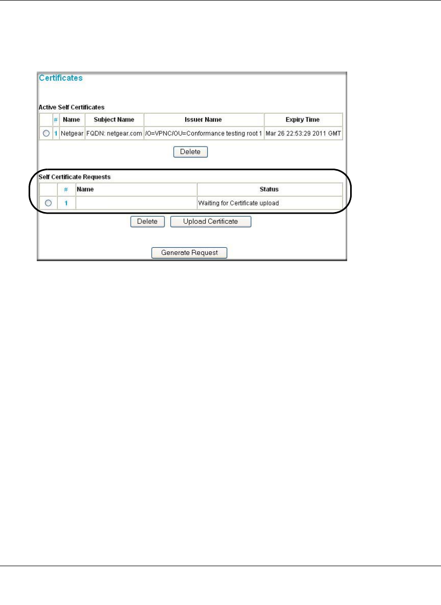
Reference Manual for the ProSafe Wireless 802.11g Firewall/Print Server Model FWG114P
Virtual Private Networking 8-29
March 2004, 202-10027-01
c. When you have finished gathering the Self Certificate Request data, click the Done button.
You will return to the Certificates screen where your pending “FWG114P” Self Certificate
Request will be listed, as illustrated in Figure 8-19 below.
Figure 8-19: Self Certificate Requests table
5. Receive the certificate back from the Trusted Root CA and save it as a text file.
Note: In the case of a Windows 2000 internal CA, the CA administrator might simply e-mail it
to back to you. Follow the procedures of your CA. Save the certificate you get back from the
CA as a text file called final.txt.
6. Upload the new certificate.
a. From the main menu VPN section, click on the Certificates link.
b. Click the radio button of the Self Certificate Request you want to upload.
c. Click the Upload Certificate button.
d. Browse to the location of the file you saved in step 5 above which contains the certificate
from the CA.
e. Click the Upload button.
FWG114P
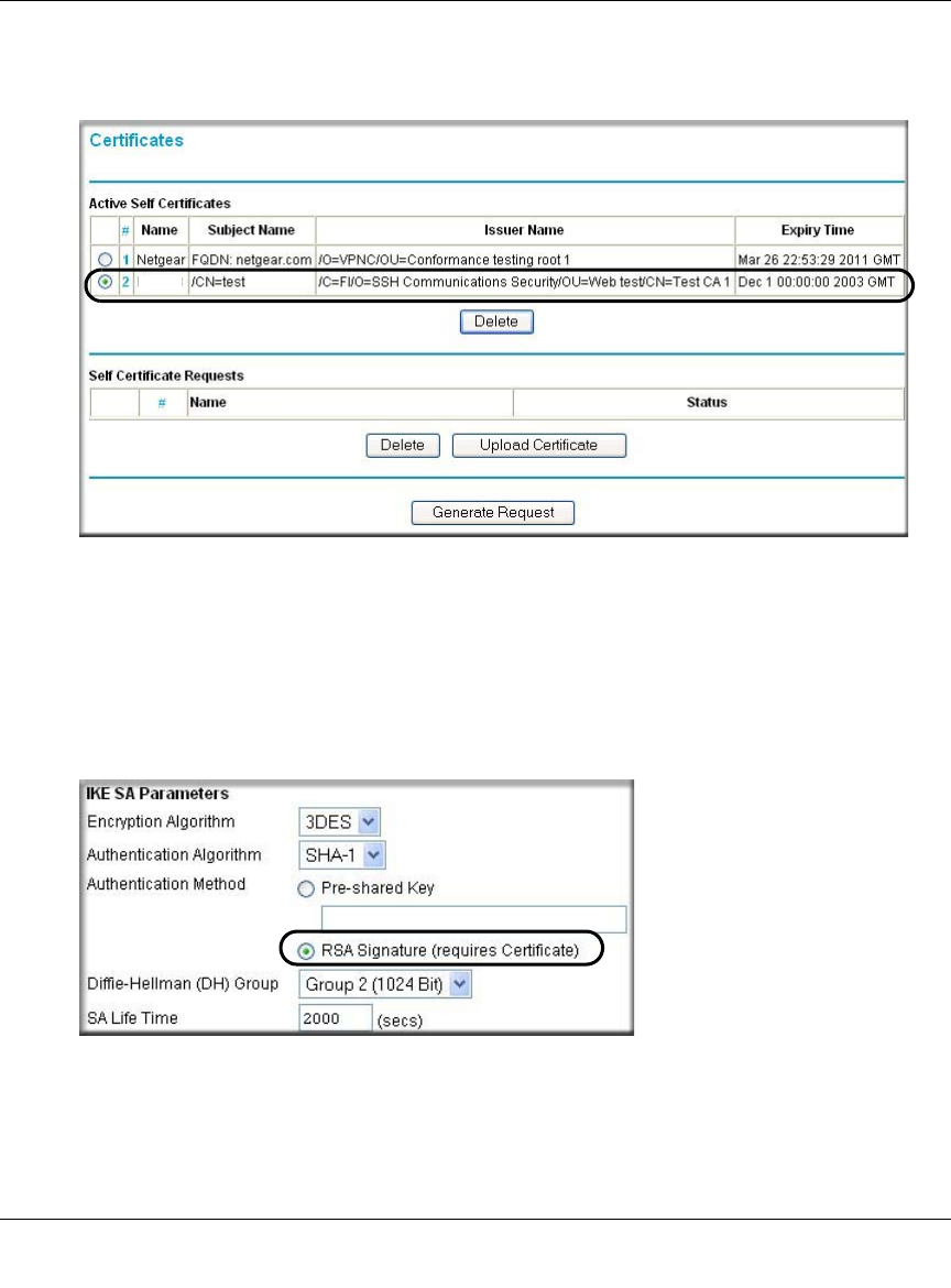
Reference Manual for the ProSafe Wireless 802.11g Firewall/Print Server Model FWG114P
8-30 Virtual Private Networking
March 2004, 202-10027-01
f. You will now see the “FWG114P” entry in the Active Self Certificates table and the
pending “FWG114P” Self Certificate Request is gone, as illustrated below.
Figure 8-20: Self Certificates table
7. Associate the new certificate and the Trusted Root CA certificate on the FWG114P.
a. Create a new IKE policy called Scenario_2 with all the same properties of Scenario_1
(see “Scenario 1 IKE Policy” on page 8-22) except now use the RSA Signature instead of
the shared key.
Figure 8-21: IKE policy using RSA Signature
b. Create a new VPN Auto Policy called scenario2a with all the same properties as
scenario1a except that it uses the IKE policy called Scenario_2.
FWG1

Reference Manual for the ProSafe Wireless 802.11g Firewall/Print Server Model FWG114P
Virtual Private Networking 8-31
March 2004, 202-10027-01
Now, the traffic from devices within the range of the LAN subnet addresses on FWG114P A
and Gateway B will be authenticated using the certificates rather than via a shared key.
8. Set up Certificate Revocation List (CRL) checking.
a. Get a copy of the CRL from the CA and save it as a text file.
Note: The procedure for obtaining a CRL differs from a CA like Verisign and a CA, such
as a Windows 2000 certificate server, which an organization operates for providing
certificates for its members. Follow the procedures of your CA.
b. From the main menu VPN section, click on the CRL link.
c. Click Add to add a CRL.
d. Click Browse to locate the CRL file.
e. Click Upload.
Now expired or revoked certificates will not be allowed to use the VPN tunnels managed by
IKE policies which use this CA.
Note: You must update the CRLs regularly in order to maintain the validity of the
certificate-based VPN policies.

Reference Manual for the ProSafe Wireless 802.11g Firewall/Print Server Model FWG114P
8-32 Virtual Private Networking
March 2004, 202-10027-01
Netgear VPN Client to FWG114P
Follow these procedures to configure a VPN tunnel from a NETGEAR ProSafe VPN Client to an
FWG114P. This case study follows the Virtual Private Network Consortium (VPNC)
interoperability profile guidelines. The menu options for the FVS328, FVL328, FWAG114, and
FWG114P are the same.
Configuration Profile
The configuration in this document follows the addressing and configuration mechanics defined
by the VPN Consortium. Gather all the necessary information before you begin the configuration
process. Verify whether the firmware is up to date, all of the addresses that will be necessary, and
all of the parameters that need to be set on both sides. Check that there are no firewall restrictions.
Table 8-1. Summary
VPN Consortium Scenario: Scenario 1
Type of VPN PC/Client-to-Gateway
Security Scheme: IKE with Preshared Secret/Key (not Certificate-based)
Date Tested: December 2003
Model/Firmware Tested:
Gateway FWG114P firmware v 2.2
Client NETGEAR ProSafe VPN Client v10.1
IP Addressing:
Gateway Static IP address
Client Dynamic
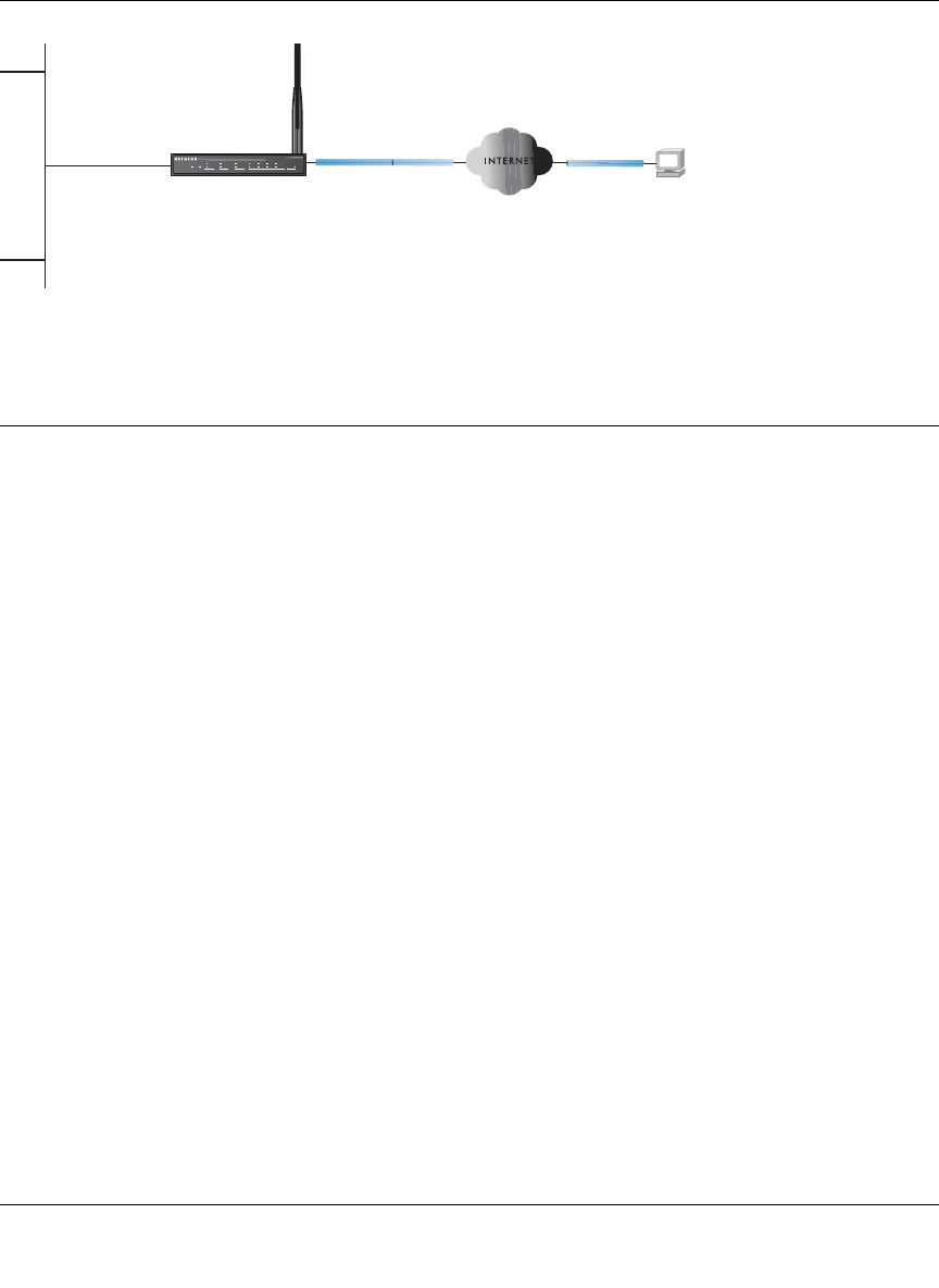
Reference Manual for the ProSafe Wireless 802.11g Firewall/Print Server Model FWG114P
Virtual Private Networking 8-33
March 2004, 202-10027-01
Figure 8-22: Addressing and Subnet Used for Examples
Step-By-Step Configuration of FWG114P Gateway
1. Log in to the FWG114P gateway as in the illustration.
Out of the box, the FWG114P is set for its default LAN address of http://192.168.0.1, with its
default user name of admin and default password of password.
/$1,3
*DWHZD\
:$1,3 :$1,3
1HWZRUN$GGUHVVHV
&OLHQW
3&ZLWK1(7*($5
3UR6DIH931FOLHQW
):*3
+Á.?wjËoåÔ±¤¤~Ë8ÁjjÄÄËÁjÝ?Ê+ÁÍË.jÁÜjÁ
Á?aM?a # 8¤¤|+
3:5
02).4%2 -/$%- ).4%2.%4 ,/#!, 7,!.
7(67
$&7
$/(57
$&7
$/(57
/1.$&7
/1.$&7
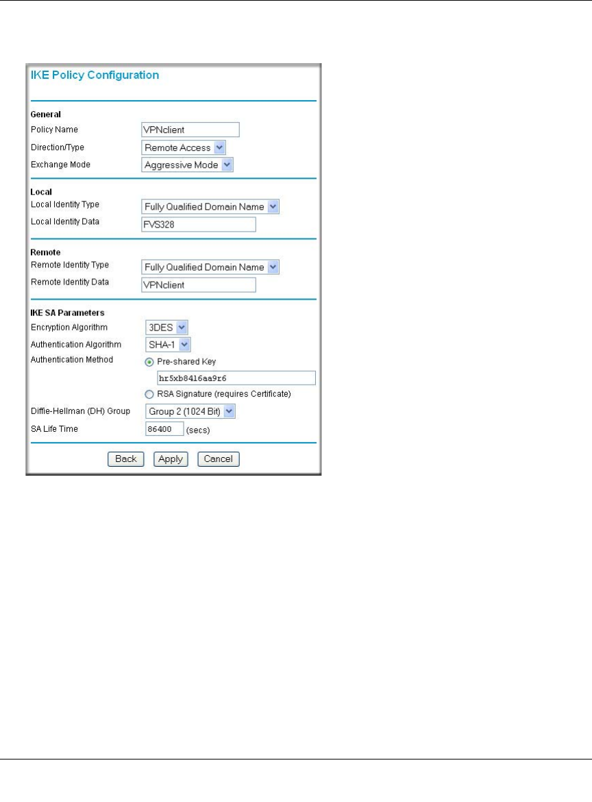
Reference Manual for the ProSafe Wireless 802.11g Firewall/Print Server Model FWG114P
8-34 Virtual Private Networking
March 2004, 202-10027-01
2. Click IKE Policies under the VPN menu and click Add on the IKE Policies Menu.
Figure 8-23: NETGEAR FWG114P IKE Policy Configuration
– Enter a descriptive name for the policy in the Policy Name field. This name is not supplied
to the remote VPN endpoint. It is used to help you manage the IKE policies. In our
example, we used VPNclient as the Policy Name.
– From the Direction/Type drop-down box, select Remote Access.
– From the Exchange Mode drop-down box, select Aggressive Mode. This will also be
selected in the VPN Client My Identity ID Type fields, as seen in “Security Policy” on
page 8-41.
– From the Local Identity drop-down box, select Fully Qualified Domain Name (the actual
WAN IP address of the FWG114P will also be used in the Connection ID Type fields of
the VPN Client as seen in “Security Policy Editor New Connection” on page 8-39).
– For this example we typed FWG114P in the Local Identity Data field.

Reference Manual for the ProSafe Wireless 802.11g Firewall/Print Server Model FWG114P
Virtual Private Networking 8-35
March 2004, 202-10027-01
– From the Remote Identity drop-down box, select Fully Qualified Domain Name.
–Type VPNclient in the Remote Identity Data. This will also be entered in the VPN Client
My Identity ID Type fields, as seen in “My Identity” on page 8-40.
– From the Encryption Algorithm drop-down box, select 3DES. This will also be selected in
the VPN Client Security Policy Authentication Phase 1 Proposal 1 Encrypt Alg field, as
seen in “Connection Security Policy Authentication (Phase 1)” on page 8-42.
– From the Authentication Algorithm drop-down box, select SHA-1.This will also be
selected in the VPN Client Security Policy Authentication Phase 1 Proposal 1 Hash Alg
field, as seen in “Connection Security Policy Authentication (Phase 1)” on page 8-42.
– From the Authentication Method radio button, select Pre-shared Key. This will also be
selected in the VPN Client Security Policy Authentication Phase 1 Proposal 1
Authentication Method field, as seen in “Connection Security Policy Authentication
(Phase 1)” on page 8-42.
– In the Pre-Shared Key field, type hr5xb84l6aa9r6. You must make sure the key is the
same for both the client and the FWG114P Wireless Firewall/Print Server. This will also
be selected in the VPN client Security Policy Authentication Phase 1 Proposal 1 Encrypt
Alg field, as seen in “Connection Identity Pre-Shared Key” on page 8-41.
– From the Diffie-Hellman (DH) Group drop-down box, select Group 2 (1024 Bit). This
will also be selected in the VPN Client Security Policy Authentication Phase 1 Proposal 1
Key Group field, as seen in “Connection Security Policy Authentication (Phase 1)” on
page 8-42.
–In the SA Life Time field, type 86400.
Click Apply. This will bring you back to the IKE Policies Menu.The FWG114P IKE Policy is
now displayed in the IKE Policies page.
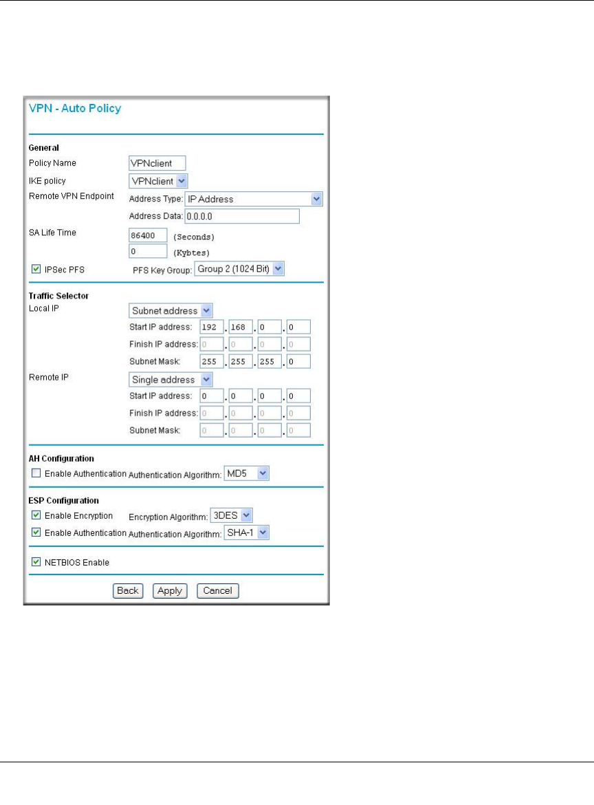
Reference Manual for the ProSafe Wireless 802.11g Firewall/Print Server Model FWG114P
8-36 Virtual Private Networking
March 2004, 202-10027-01
3. Click the VPN Policies link under the VPN category on the left side of the main menu. This
will take you to the VPN Policies Menu page. Click Add Auto Policy. This will open a new
screen titled VPN – Auto Policy.
Figure 8-24: VPN – Auto Policy settings
– Enter a unique name to identify this policy. This name is not supplied to the remote VPN
endpoint. In our example, we use VPNclient as the Policy Name.
– From the IKE policy drop-down box, select VPNclient which is the IKE Policy that was
set up in the earlier step.

Reference Manual for the ProSafe Wireless 802.11g Firewall/Print Server Model FWG114P
Virtual Private Networking 8-37
March 2004, 202-10027-01
– From the Remote VPN Endpoint Address Type drop-down box, select IP Address.
–Type 0.0.0.0 as the Address Data of the client because we are assuming the remote PC will
have a dynamically assigned IP address. This will also be entered in the VPN Client
Internal Network IP Address field, as seen in “My Identity” on page 8-40.
–Type 86400 in the SA Life Time (Seconds) field.
–Type 0 in the SA Life Time (Kbytes) field.
– Check the IPSec PFS check box to enable Perfect Forward Secrecy. This will also be
entered in the VPN Client Security Policy Enable Perfect Forward Secrecy check box, as
seen in “Security Policy” on page 8-41.
– From the PFS Key Group drop-down box, select Group 2 (1024 Bit). This will also be
entered in the VPN Client Security Policy PFS Key Group drop-down selection box, as
seen in “Security Policy” on page 8-41.
– From the Traffic Selector Local IP drop-down box, select Subnet addresses. This will
also be entered in the VPN Client Connection Remote Party Identity and Addressing ID
Type field, as seen in “Security Policy Editor New Connection” on page 8-39.
Note: Selecting ANY for the Traffic Selectors means all traffic goes through the IPSec
tunnel and prevents access to the Internet.
– Type the starting LAN IP Address of the FWG114P in the Local IP Start IP Address field.
For this example, we used 192.168.0.0 which is the default LAN IP address of the
FWG114P. This will also be entered in the VPN Client Connection Remote Party Identity
and Addressing Subnet field, as seen in “Security Policy Editor New Connection” on page
8-39.
– Type the LAN Subnet Mask of the FWG114P (255.255.255.0 in our example) in the Local
IP Subnet Mask field. This will also be entered in the VPN Client Connection Remote
Party Identity and Addressing Mask field, as seen in “Security Policy Editor New
Connection” on page 8-39.
– From the Traffic Selector Remote IP drop-down box, select Single addresses.
–Type 0.0.0.0 as the start IP Address of the in the Remote IP Start IP Address field because
we are assuming the remote PC will have a dynamically assigned IP address. This will
also be entered in the VPN Client My Identity Internal Network IP Address field, as seen
in “My Identity” on page 8-40.
– Select the Enable Encryption check box. This will also be selected in the VPN Client
Security Policy Key Exchange (Phase 2) Encapsulation Protocol (ESP) check box, as seen
in “Connection Security Policy Key Exchange (Phase 2)” on page 8-43.
– From the ESP Configuration Encryption Algorithm drop-down box, select 3DES. This
will also be entered in the VPN Client Security Policy Key Exchange (Phase 2) Encrypt
Alg field, as seen in “Connection Security Policy Key Exchange (Phase 2)” on page 8-43.
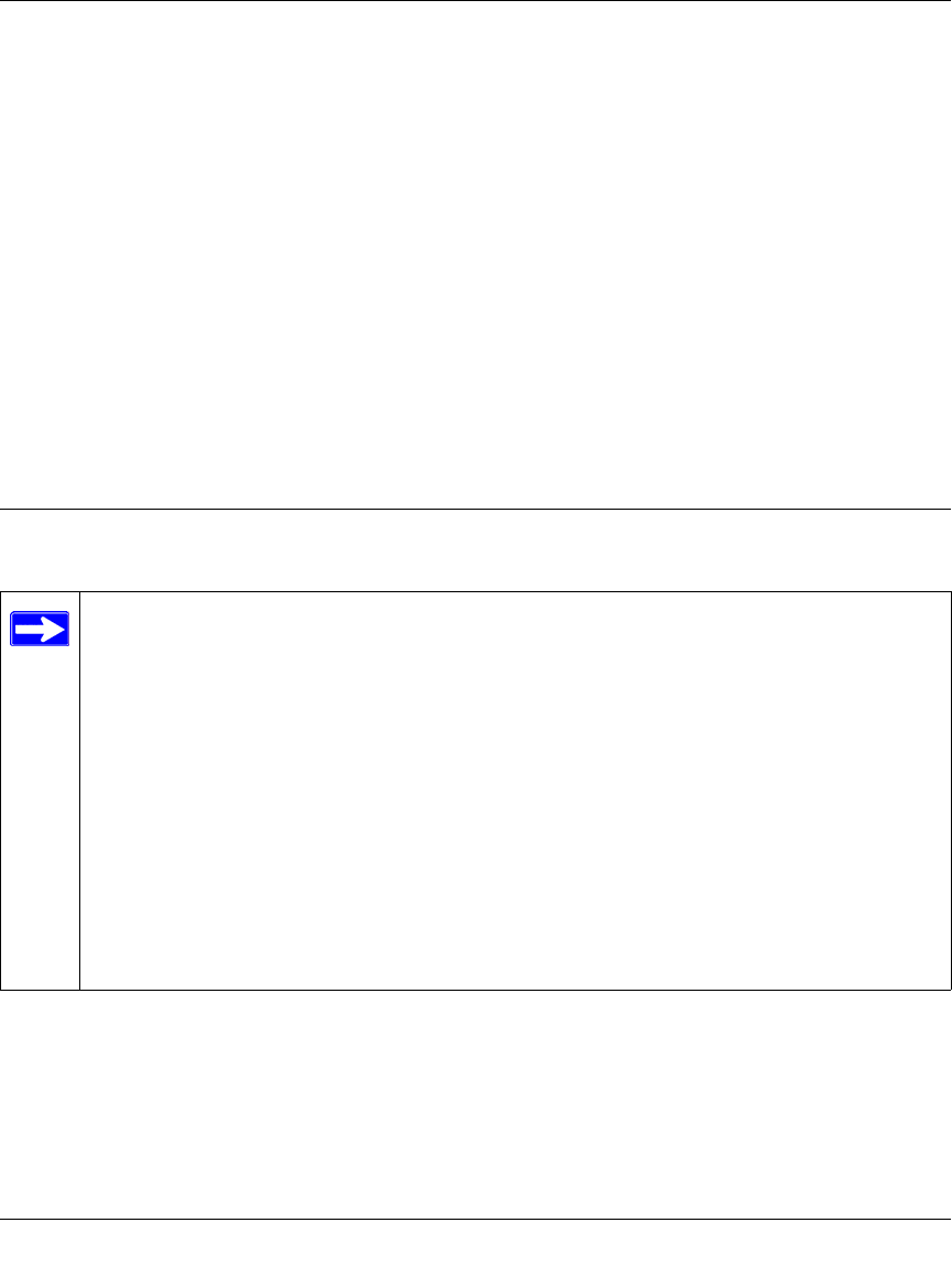
Reference Manual for the ProSafe Wireless 802.11g Firewall/Print Server Model FWG114P
8-38 Virtual Private Networking
March 2004, 202-10027-01
– Select Enable Authentication in the ESP Configuration Enable Authentication check
box.
Note: Do not confuse this with the Authentication Protocol (AH) option. Using the AH
option will prevent clients behind a home NAT router from connecting.
– From the ESP Configuration Authentication Algorithm drop-down box, select SHA-1.
This will also be entered in the VPN Client Security Policy Key Exchange (Phase 2) Hash
Alg field, as seen in “Connection Security Policy Key Exchange (Phase 2)” on page 8-43.
– Select the NETBIOS Enable check box to enable networking features like Windows
Network Neighborhood.
Click Apply to save your changes. You will be taken back to the VPN Policies Menu page.
4. When the screen returns to the VPN Policies, make sure the Enable check box is selected.
Click Apply to save your changes.
Step-By-Step Configuration of the Netgear VPN Client
This procedure describes linking a remote PC and a LAN. The LAN will connect to the Internet
using an FWG114P with a static IP address. The PC can be directly connected to the Internet
through dialup, cable or DSL modem, or other means, and we will assume it has a dynamically
assigned IP address.
Note: The Netgear ProSafe VPN Client has the ability to “Import” a predefined
configuration profile. The FWG114P.SPD file on the ProSafe Wireless 802.11g
Firewall/Print Server Model FWG114P Resource CD for the ProSafe Wireless 802.11g
Firewall/Print Server Model FWG114P (SW-10023-02) includes all the settings
identified in this procedure.
Whenever importing policy settings, you should first export any existing settings you
may have configured to prevent the new imported settings from replacing an existing
working configuration.
To import this policy, use the Security Policy Editor File menu to select Import Policy,
and select the FWG114P.SPD file at D:\Software\Policies where D is the drive letter of
your CD-ROM drive.
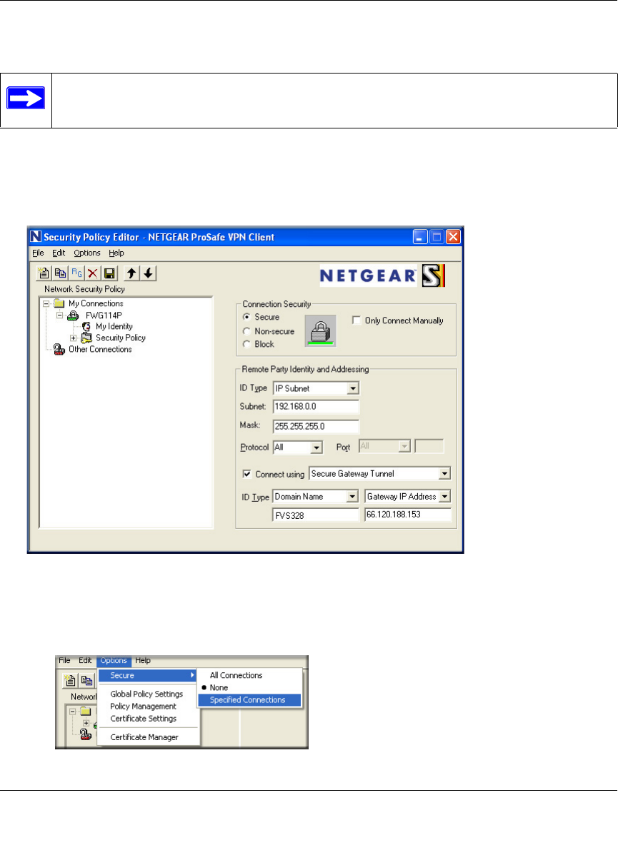
Reference Manual for the ProSafe Wireless 802.11g Firewall/Print Server Model FWG114P
Virtual Private Networking 8-39
March 2004, 202-10027-01
1. Install the Netgear VPN Client Software on the PC.
• You may need to insert your Windows CD to complete the installation.
• Reboot your PC after installing the client software.
2. Configure the Connection Network Settings.
Figure 8-25: Security Policy Editor New Connection
a. Run the Security Policy Editor program and create a VPN Connection.
Figure 8-26: Security Policy Editor Options menu
Note: Before installing the Netgear VPN Client software, be sure to turn off any virus
protection or firewall software you may be running on your PC.
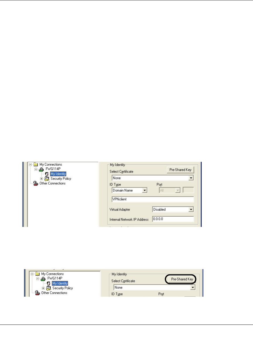
Reference Manual for the ProSafe Wireless 802.11g Firewall/Print Server Model FWG114P
8-40 Virtual Private Networking
March 2004, 202-10027-01
Note: If the configuration settings on this screen are not available for editing, go to the
Options menu, select Secure, and Specified Options to enable editing these settings.
From the Edit menu of the Security Policy Editor, click Add, then Connection. A “New
Connection” listing appears. Rename the “New Connection” to FWG114P.
b. Ensure that the following settings are configured:
– In the Connection Security box, Secure is selected.
– In the Protocol menu, All is selected.
– The Connect using Secure Gateway Tunnel check box is selected.
c. In this example, select IP Subnet as the ID Type, 192.168.0.0 in the Subnet field (the
Subnet address is the LAN IP Address of the FWG114P with 0 as the last number), and
255.255.255.0 in the Mask field, which is the LAN Subnet Mask of the FWG114P.
d. In the ID Type menus, select Domain Name and Gateway IP Address. Enter FWG114P
in the Domain Name field. In this example, 66.120.188.153 would be used for the
Gateway IP Address, which is the static IP address for the FWG114P WAN port.
3. Configure the Connection Identity Settings.
a. In the Network Security Policy list, click the My Identity subheading.
Figure 8-27: My Identity
In this example, select Domain Name as the ID Type, and enter VPNclient. Also, accept
the default Internal Network IP Address of 0.0.0.0.
Figure 8-28: My Identity Pre-Shared Key