New Centurion Solutions NCS03010910 HANDHELD SECURITY DEVICE User Manual Project 623
New Centurion Solutions, Inc. HANDHELD SECURITY DEVICE Project 623
Contents
- 1. Users Manual
- 2. Installation Manual
Users Manual
THE INFORMATION CONTAINED HEREIN IS PROPRIETARY TO NEW CENTURION SOLUTIONS, INC. AND SHALL NOT BE
REPRODUCED OR DISCLOSED IN WHOLE OR IN PART FOR ANY DESIGN OR MANUFACTURE EXCEPT WHEN SUCH USER
POSSESSES DIRECT, WRITTEN AUTHORIZATION FROM NEW CENTURION SOLUTIONS, INC.
Elliott Tech, LLC
IREP Assembly Manual
IREP
New Centurion Solutions
Project Number: 776
Reference: 776-91-03-REV-.docx
Original Document: March 1, 2011
Revision A: March 16, 2011
Prepared for:
Prepared by:
New Centurion Solutions, Inc.
Greg Williams
3011 Spring Garden St.
Suite E
Greensboro, NC 27403
(336) 617-5410
GWilliams@newcenturionsolutions.com
Elliott Tech, LLC
346 Raleigh Street
Holly Springs, NC 27540
(919) 342-6899
(888) 631-1795 Fax
s.elliott@elliotttech.com

IREP Assembly Manual 776-91-03-REV-A.docx
THE INFORMATION CONTAINED HEREIN IS PROPRIETARY TO NEW CENTURION SOLUTIONS, INC. AND SHALL NOT BE
REPRODUCED OR DISCLOSED IN WHOLE OR IN PART FOR ANY DESIGN OR MANUFACTURE EXCEPT WHEN SUCH USER
POSSESSES DIRECT, WRITTEN AUTHORIZATION FROM NEW CENTURION SOLUTIONS, INC.
ii
Revision Page
Rev
Description
Section
A
FCC Notification
3

IREP Assembly Manual 776-91-03-REV-A.docx
THE INFORMATION CONTAINED HEREIN IS PROPRIETARY TO NEW CENTURION SOLUTIONS, INC. AND SHALL NOT BE
REPRODUCED OR DISCLOSED IN WHOLE OR IN PART FOR ANY DESIGN OR MANUFACTURE EXCEPT WHEN SUCH USER
POSSESSES DIRECT, WRITTEN AUTHORIZATION FROM NEW CENTURION SOLUTIONS, INC.
iii
Contents
1. Equipment List ......................................................................................................... 4
2. Assembly Instructions .............................................................................................. 5
3. FCC Notification ...................................................................................................... 7
IREP Assembly Manual 776-91-03-REV-A.docx
THE INFORMATION CONTAINED HEREIN IS PROPRIETARY TO NEW CENTURION SOLUTIONS, INC. AND SHALL NOT BE REPRODUCED OR
DISCLOSED IN WHOLE OR IN PART FOR ANY DESIGN OR MANUFACTURE EXCEPT WHEN SUCH USER POSSESSES DIRECT, WRITTEN
AUTHORIZATION FROM NEW CENTURION SOLUTIONS, INC.
4
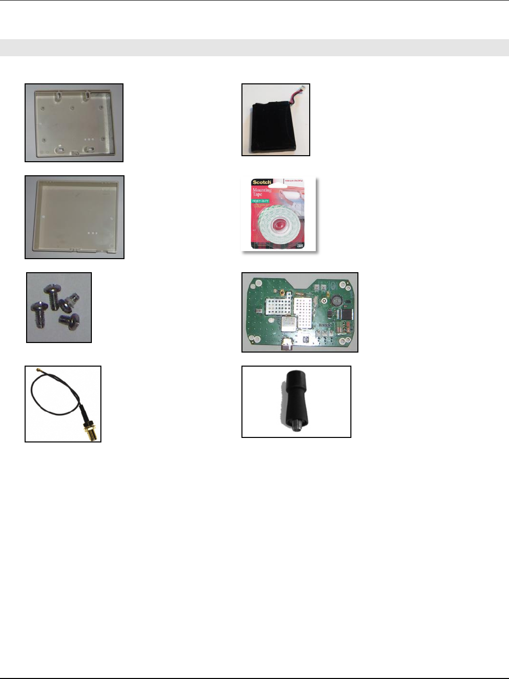
1. EQUIPMENT LIST
A. IREP Enclosure - Inside (1)
B. Tenergy Battery (1)
C. IREP Enclosure - Outside (1)
D. Double Sided Tape
E. IREP Enclosure - Screws (4)
F. IREP PCB (1)
G. Coaxial Cable RF Plug-SMA Jack (1)
H. SMA Antenna (1)
IREP Assembly Manual 776-91-03-REV-A.docx
THE INFORMATION CONTAINED HEREIN IS PROPRIETARY TO NEW CENTURION SOLUTIONS, INC. AND SHALL NOT BE REPRODUCED OR
DISCLOSED IN WHOLE OR IN PART FOR ANY DESIGN OR MANUFACTURE EXCEPT WHEN SUCH USER POSSESSES DIRECT, WRITTEN
AUTHORIZATION FROM NEW CENTURION SOLUTIONS, INC.
5
2. ASSEMBLY INSTRUCTIONS
To begin, check the parts available against the equipment list, identifying any missing parts. If all
parts are accounted for, proceed to the instructions below to begin assembling the indoor repeater
(IREP).
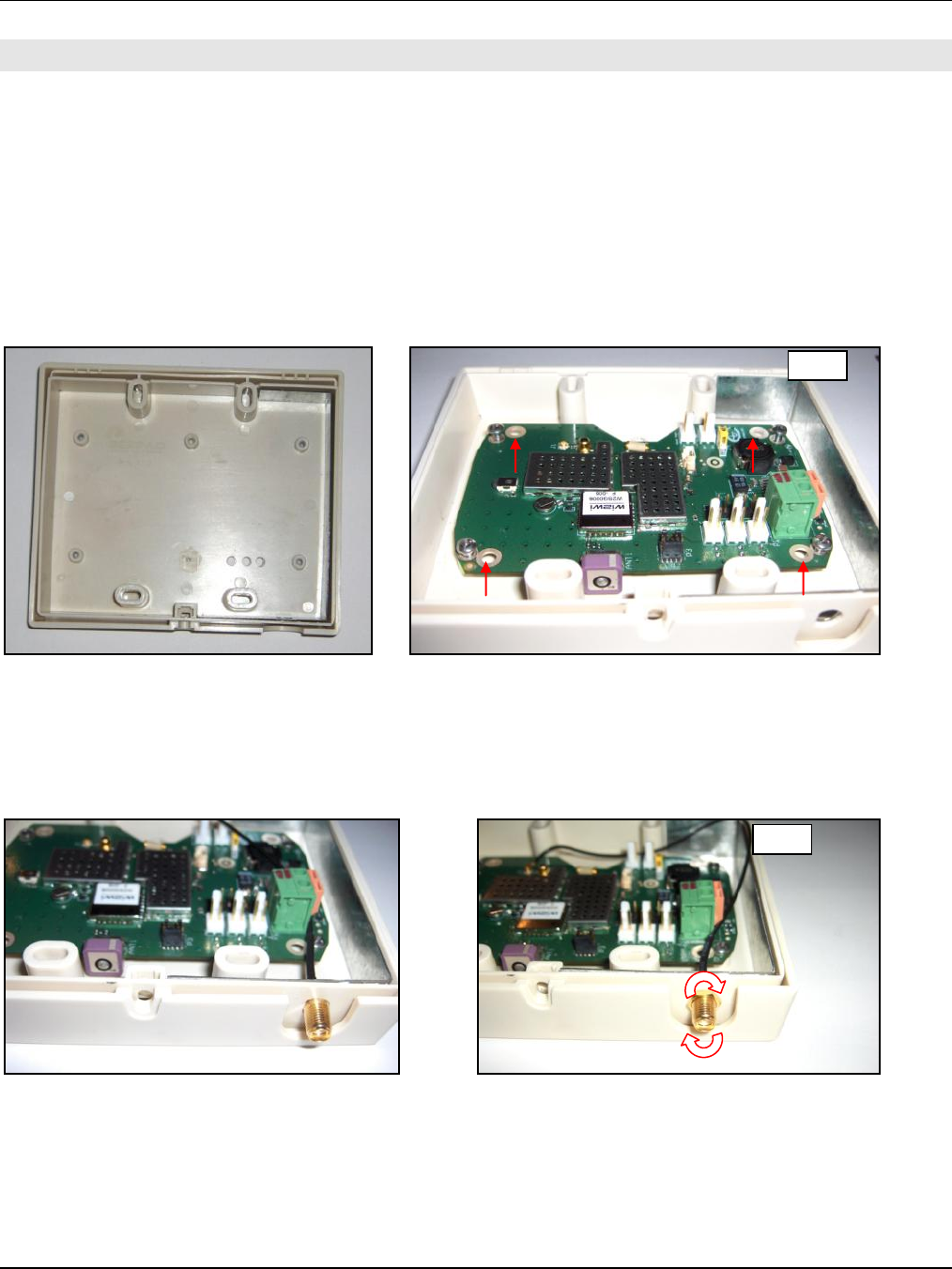
Step 1: The inside enclosure (A) should come inside of the outside enclosure (C) as indicated in
the figure below. Place the PCB (F) over the inside enclosure so that the LED’s line up with the
three consecutive holes and that the holes in each corner of the PCB line up over the screw holes
on the enclosure. Insert the enclosure screws (E) into each corner of the PCB attaching the board
to the enclosure.
Step 2: Put the washer on the end of the RF cable (G) with the jack and feed it through the
opening in the enclosure from the inside out. Rotate the nut clockwise around the outside of the
RF jack until it is flush against the enclosure.
Step 1
Step 2
IREP Assembly Manual 776-91-03-REV-A.docx
THE INFORMATION CONTAINED HEREIN IS PROPRIETARY TO NEW CENTURION SOLUTIONS, INC. AND SHALL NOT BE REPRODUCED OR
DISCLOSED IN WHOLE OR IN PART FOR ANY DESIGN OR MANUFACTURE EXCEPT WHEN SUCH USER POSSESSES DIRECT, WRITTEN
AUTHORIZATION FROM NEW CENTURION SOLUTIONS, INC.
6
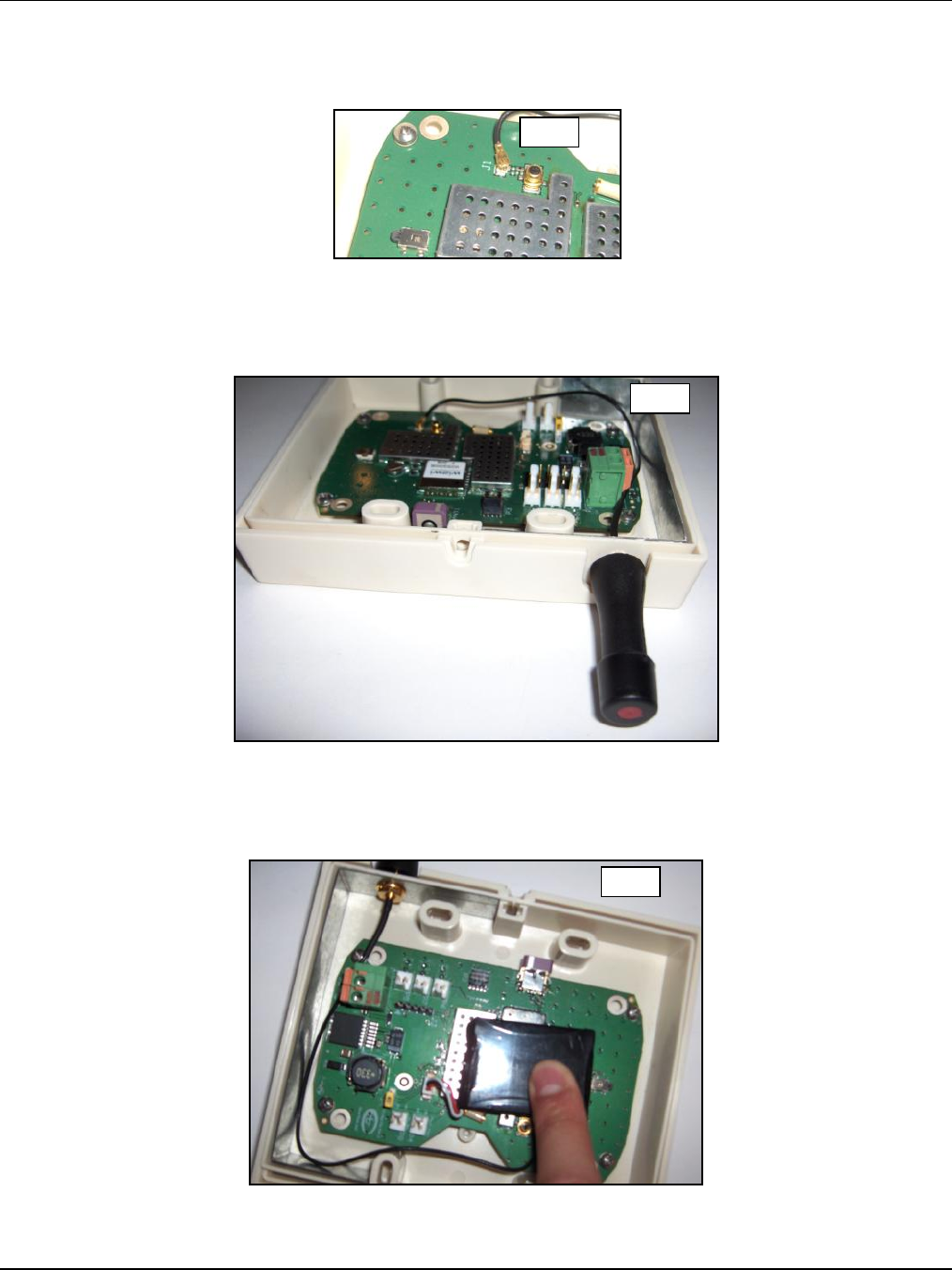
Step 3: Take the SMA plug end of the RF cable and attach it to the RF port labeled J1 on the PCB
by laying the plug over the port and pressing down. The plug should snap right into place.
Step 4: Attach the SMA Antenna to the RF jack by screwing it in clockwise to the outside of the
enclosure.
Step 5: Insert the Tenergy battery (B) connector into the 3 pin header on the PCB beside the “on”
switch. After doing so, apply a piece of double sided tape (D) to either side of the battery, and
press the battery against the metal shields on the PCB.
Step 3
Step 4
Step 5

IREP Assembly Manual 776-91-03-REV-A.docx
THE INFORMATION CONTAINED HEREIN IS PROPRIETARY TO NEW CENTURION SOLUTIONS, INC. AND SHALL NOT BE REPRODUCED OR
DISCLOSED IN WHOLE OR IN PART FOR ANY DESIGN OR MANUFACTURE EXCEPT WHEN SUCH USER POSSESSES DIRECT, WRITTEN
AUTHORIZATION FROM NEW CENTURION SOLUTIONS, INC.
7
3. FCC NOTIFICATION
NOTE: THE MANUFACTURER IS NOT RESPONSIBLE FOR ANY RADIO OR TV INTERFERENCE
CAUSED BY UNAUTHORIZED MODIFICATIONS TO THIS EQUIPMENT. SUCH MODIFICATIONS
COULD VOID THE USER’S AUTHORITY TO OPERATE THE EQUIPMENT.
THIS DEVICE COMPLIES WITH PART 15 OF THE FCC RULES. OPERATION IS SUBJECT TO THE
FOLLOWING TWO CONDITIONS: (1) THIS DEVICE MAY NOT CAUSE HARMFUL INTERFERENCE, AND
(2) THIS DEVICE MUST ACCEPT ANY INTERFERENCE RECEIVED, INCLUDING INTERFERENCE THAT
MAY CAUSE UNDESIRED OPERATION.