New Centurion Solutions NCS03010910 HANDHELD SECURITY DEVICE User Manual Project 623
New Centurion Solutions, Inc. HANDHELD SECURITY DEVICE Project 623
Contents
- 1. Users Manual
- 2. Installation Manual
Installation Manual

THE INFORMATION CONTAINED HEREIN IS PROPRIETARY TO NEW CENTURION SOLUTIONS, INC. AND SHALL NOT BE
REPRODUCED OR DISCLOSED IN WHOLE OR IN PART FOR ANY DESIGN OR MANUFACTURE EXCEPT WHEN SUCH USER
POSSESSES DIRECT, WRITTEN AUTHORIZATION FROM NEW CENTURION SOLUTIONS, INC.
Elliott Tech, LLC
IREP Installation Manual
IREP
New Centurion Solutions
Project Number: 776
Reference: 776-91-06-REV-IREP_INSTALLATION_MANUAL.docx
Original Document: March 1, 2011
Revision A: March 16, 2011
Prepared for:
Prepared by:
New Centurion Solutions, Inc.
Greg Williams
3011 Spring Garden St.
Suite E
Greensboro, NC 27403
(336) 617-5410
GWilliams@newcenturionsolutions.com
Elliott Tech, LLC
346 Raleigh Street
Holly Springs, NC 27540
(919) 342-6899
(888) 631-1795 Fax
s.elliott@elliotttech.com

IREP Installation Manual 776-91-06-REV-A_IREP_INSTALLATION_MANUAL.docx
THE INFORMATION CONTAINED HEREIN IS PROPRIETARY TO NEW CENTURION SOLUTIONS, INC. AND SHALL NOT BE
REPRODUCED OR DISCLOSED IN WHOLE OR IN PART FOR ANY DESIGN OR MANUFACTURE EXCEPT WHEN SUCH USER
POSSESSES DIRECT, WRITTEN AUTHORIZATION FROM NEW CENTURION SOLUTIONS, INC.
ii
Revision Page
Rev
Description
Section
A
FCC Notification
3

IREP Installation Manual 776-91-06-REV-A_IREP_INSTALLATION_MANUAL.docx
THE INFORMATION CONTAINED HEREIN IS PROPRIETARY TO NEW CENTURION SOLUTIONS, INC. AND SHALL NOT BE
REPRODUCED OR DISCLOSED IN WHOLE OR IN PART FOR ANY DESIGN OR MANUFACTURE EXCEPT WHEN SUCH USER
POSSESSES DIRECT, WRITTEN AUTHORIZATION FROM NEW CENTURION SOLUTIONS, INC.
iii
Contents
1. Equipment List ......................................................................................................... 4
2. Installation Prerequisties ........................................................................................ 5
3. Installation Instructions .......................................................................................... 5
4. FCC Notification ...................................................................................................... 6
IREP Installation Manual 776-91-06-REV-A_IREP_INSTALLATION_MANUAL.docx
THE INFORMATION CONTAINED HEREIN IS PROPRIETARY TO NEW CENTURION SOLUTIONS, INC. AND SHALL NOT BE REPRODUCED OR
DISCLOSED IN WHOLE OR IN PART FOR ANY DESIGN OR MANUFACTURE EXCEPT WHEN SUCH USER POSSESSES DIRECT, WRITTEN
AUTHORIZATION FROM NEW CENTURION SOLUTIONS, INC.
4
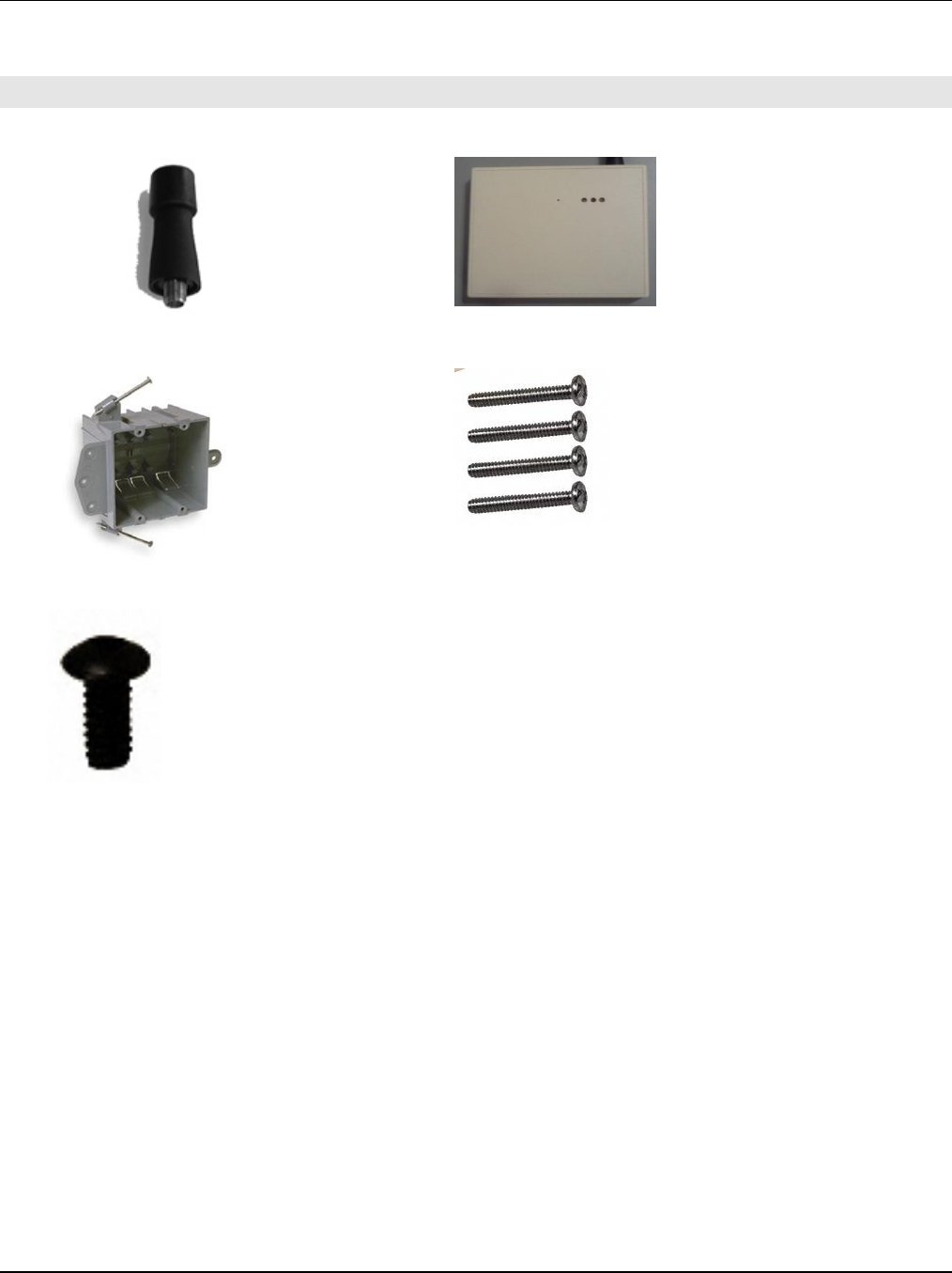
1. EQUIPMENT LIST
A. Antenna, helical short ¼ wave (1)
B. IREP Assembly (1)
C. Double-gang box installation (pre-requisite)
D. #6-32 pan head screw (4) – included with IREP
assembly
E. #6-32 x 1” button-head screw (1) – included
with IREP assembly
IREP Installation Manual 776-91-06-REV-A_IREP_INSTALLATION_MANUAL.docx
THE INFORMATION CONTAINED HEREIN IS PROPRIETARY TO NEW CENTURION SOLUTIONS, INC. AND SHALL NOT BE REPRODUCED OR
DISCLOSED IN WHOLE OR IN PART FOR ANY DESIGN OR MANUFACTURE EXCEPT WHEN SUCH USER POSSESSES DIRECT, WRITTEN
AUTHORIZATION FROM NEW CENTURION SOLUTIONS, INC.
5
2. INSTALLATION PREREQUISTIES
Ensure that the following installation prerequisite is met:
Wiring and installation of double-gang box
3. INSTALLATION INSTRUCTIONS
To begin, check the parts available against the equipment list, identifying any missing parts. If all
parts are accounted for, proceed to the instructions below to begin installing the IREP.
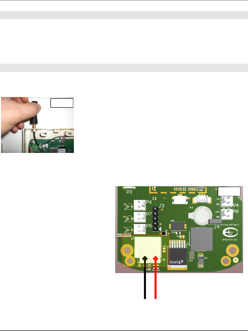
Step 1: Identify the Antenna, helical short ¼ wave (A). Screw the
antenna into the gold coaxial antenna connector on the top of the
IREP assembly (B). Ensure that the antenna is screwed onto the
connector snugly, but take care not to over-tighten the antenna as
it will damage the connector or the IREP assembly enclosure.
Step 2: Identify the power supply wires located within the double-gang installation. Ensure that
the positive and negative wires are identified before proceeding with the installation.
Identify the green and orange terminal block on the IREP Printed Circuit Board (PCB). Note the “+”
silkscreen market on the PCB just to the
lower right of the terminal block. Connect
the positive power supply wire to the
terminal block connection distinguished by
the “+” marker, and connect the negative
power supply wire to the opposite terminal
block connection.
The green LED on the front of the IREP
enclosure should illuminate when power is
correctly connected.
Type-A
(+)
(-)
Step 1
Step 2
IREP Installation Manual 776-91-06-REV-A_IREP_INSTALLATION_MANUAL.docx
THE INFORMATION CONTAINED HEREIN IS PROPRIETARY TO NEW CENTURION SOLUTIONS, INC. AND SHALL NOT BE REPRODUCED OR
DISCLOSED IN WHOLE OR IN PART FOR ANY DESIGN OR MANUFACTURE EXCEPT WHEN SUCH USER POSSESSES DIRECT, WRITTEN
AUTHORIZATION FROM NEW CENTURION SOLUTIONS, INC.
6
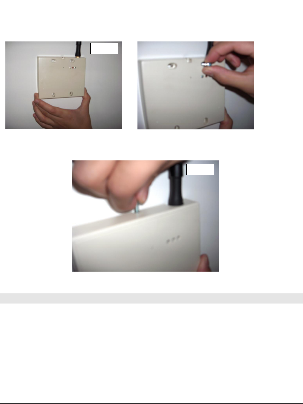
Step 3: Identify the #6-32 pan head screw (D). Ensure that the outer half of the enclosure is
detached from the inner half. Secure the inner half of the IREP (connected to wires) assembly to
the double-gang box with four of these screws.
Step 4: Identify the outer half of the IREP enclosure. Secure this half over the first half using the
#6-32 x 1” button-head screw (E) at the top center of the IREP.
4. FCC NOTIFICATION
NOTE: THE MANUFACTURER IS NOT RESPONSIBLE FOR ANY RADIO OR TV INTERFERENCE
CAUSED BY UNAUTHORIZED MODIFICATIONS TO THIS EQUIPMENT. SUCH MODIFICATIONS
COULD VOID THE USER’S AUTHORITY TO OPERATE THE EQUIPMENT.
THIS DEVICE COMPLIES WITH PART 15 OF THE FCC RULES. OPERATION IS SUBJECT TO THE
FOLLOWING TWO CONDITIONS: (1) THIS DEVICE MAY NOT CAUSE HARMFUL INTERFERENCE, AND
(2) THIS DEVICE MUST ACCEPT ANY INTERFERENCE RECEIVED, INCLUDING INTERFERENCE THAT
MAY CAUSE UNDESIRED OPERATION.
Step 3
Step 4