NiCOM USA NT350FP07 350W TRANSMITTER User Manual NT350
NiCOM USA 350W TRANSMITTER NT350
UserManual.wiki
>
NiCOM USA
>
NT350FP07 User Manual
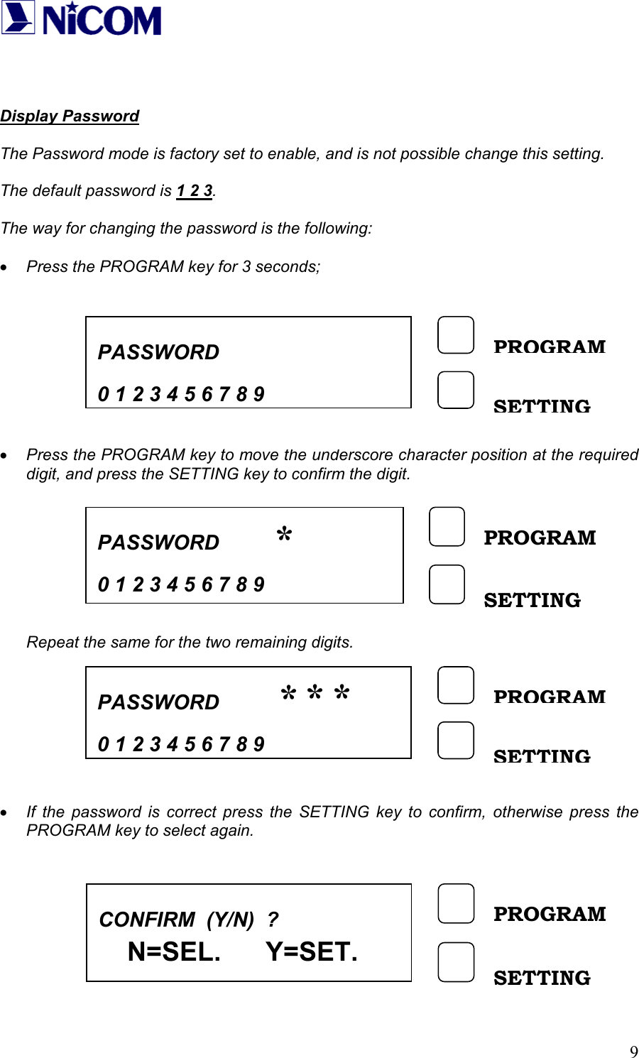
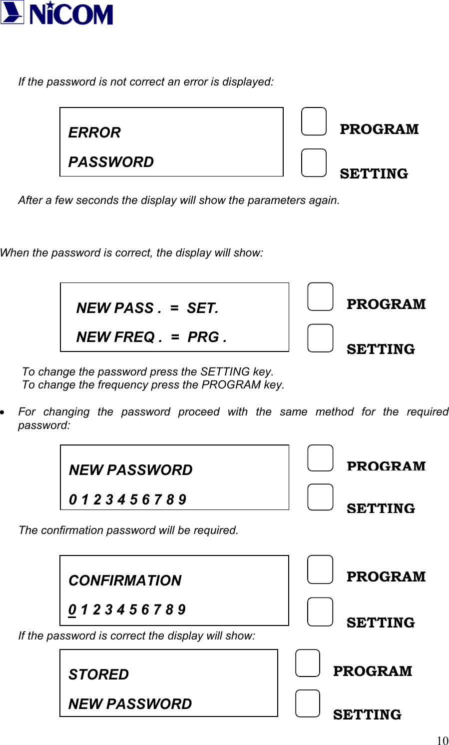
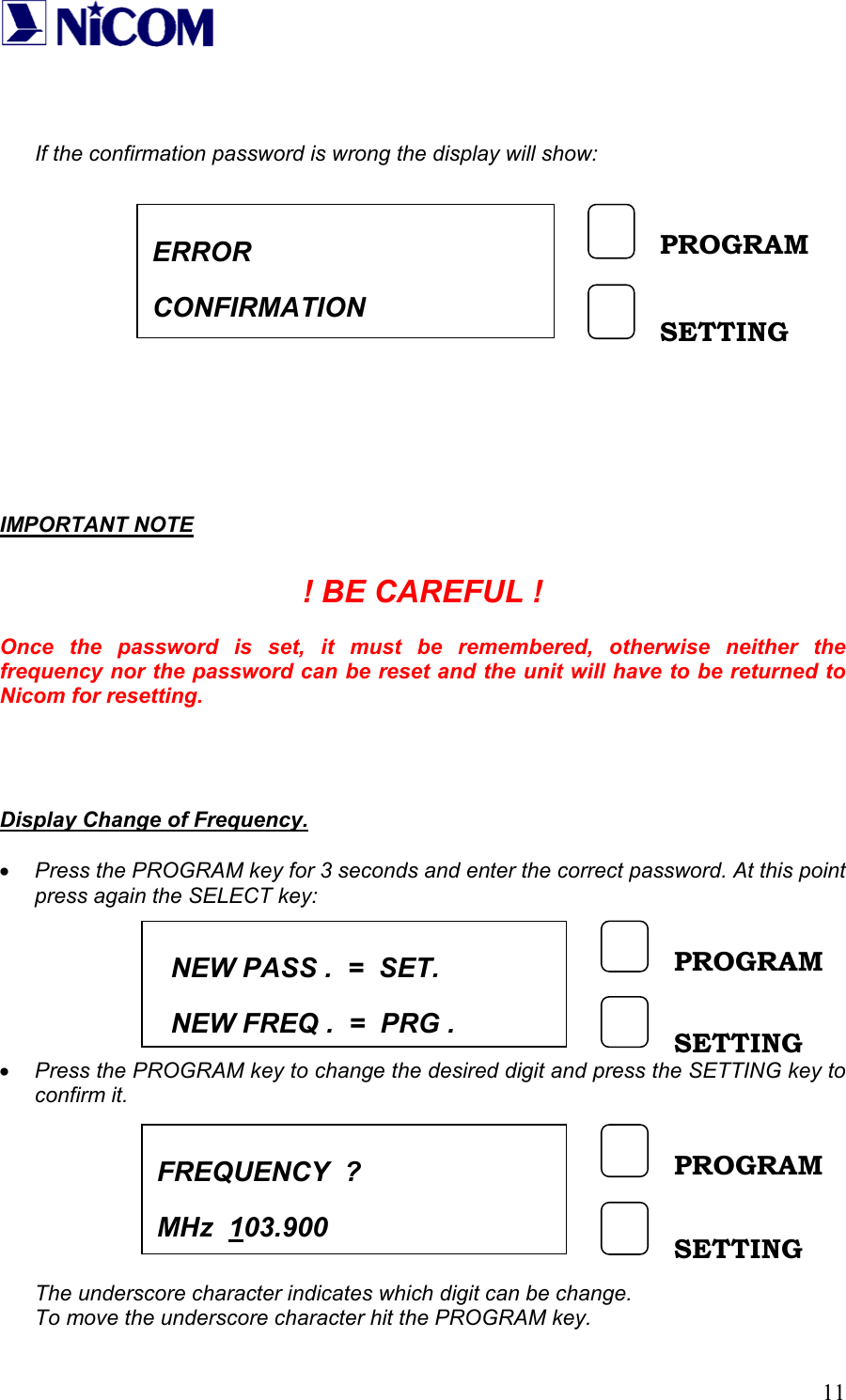
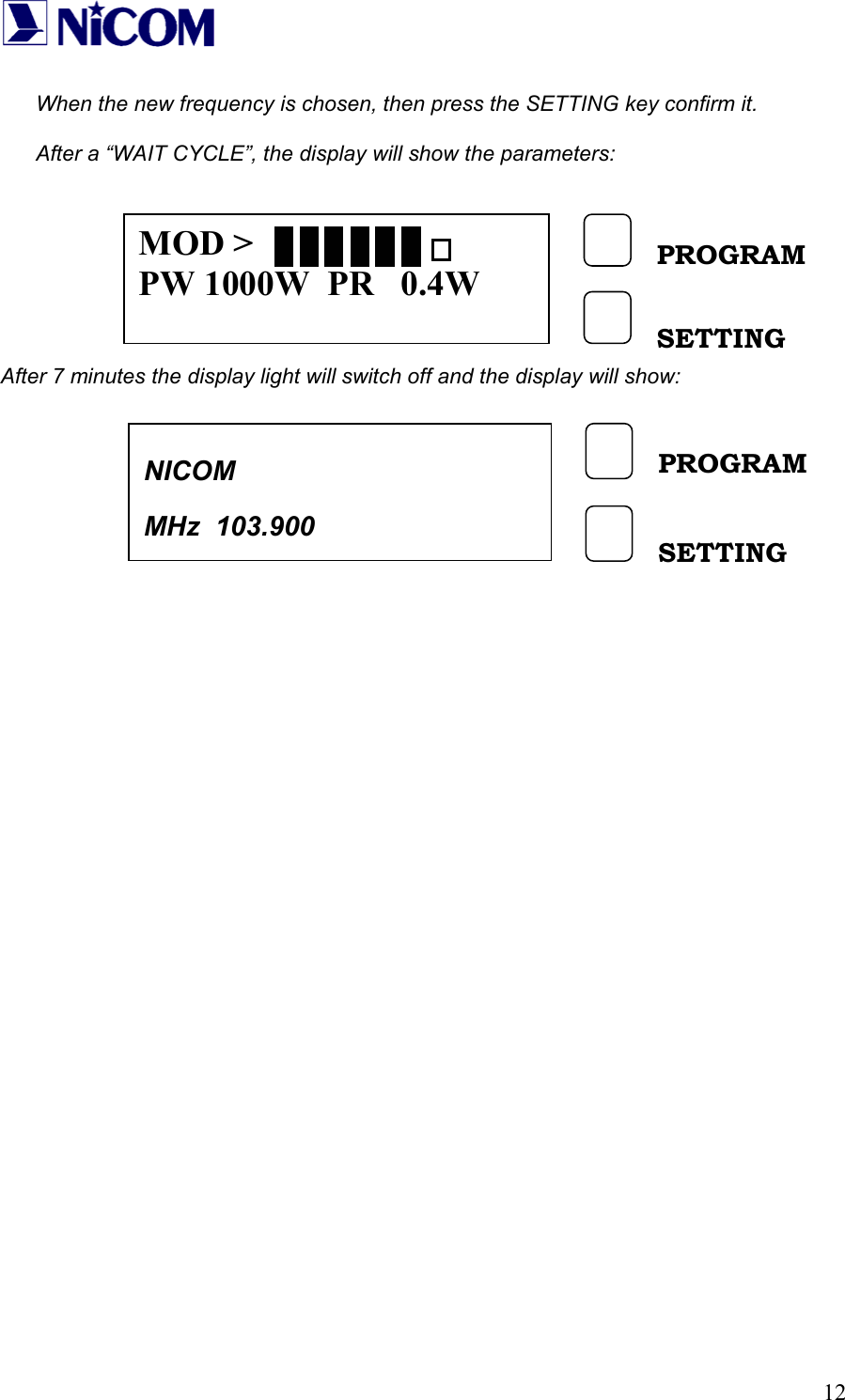
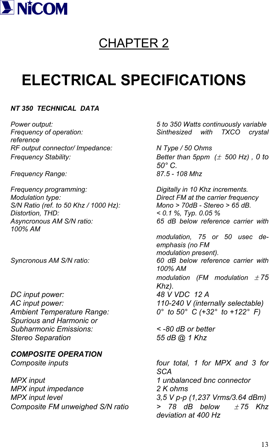
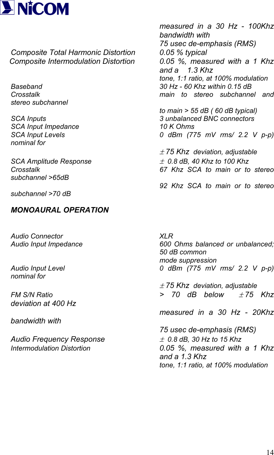
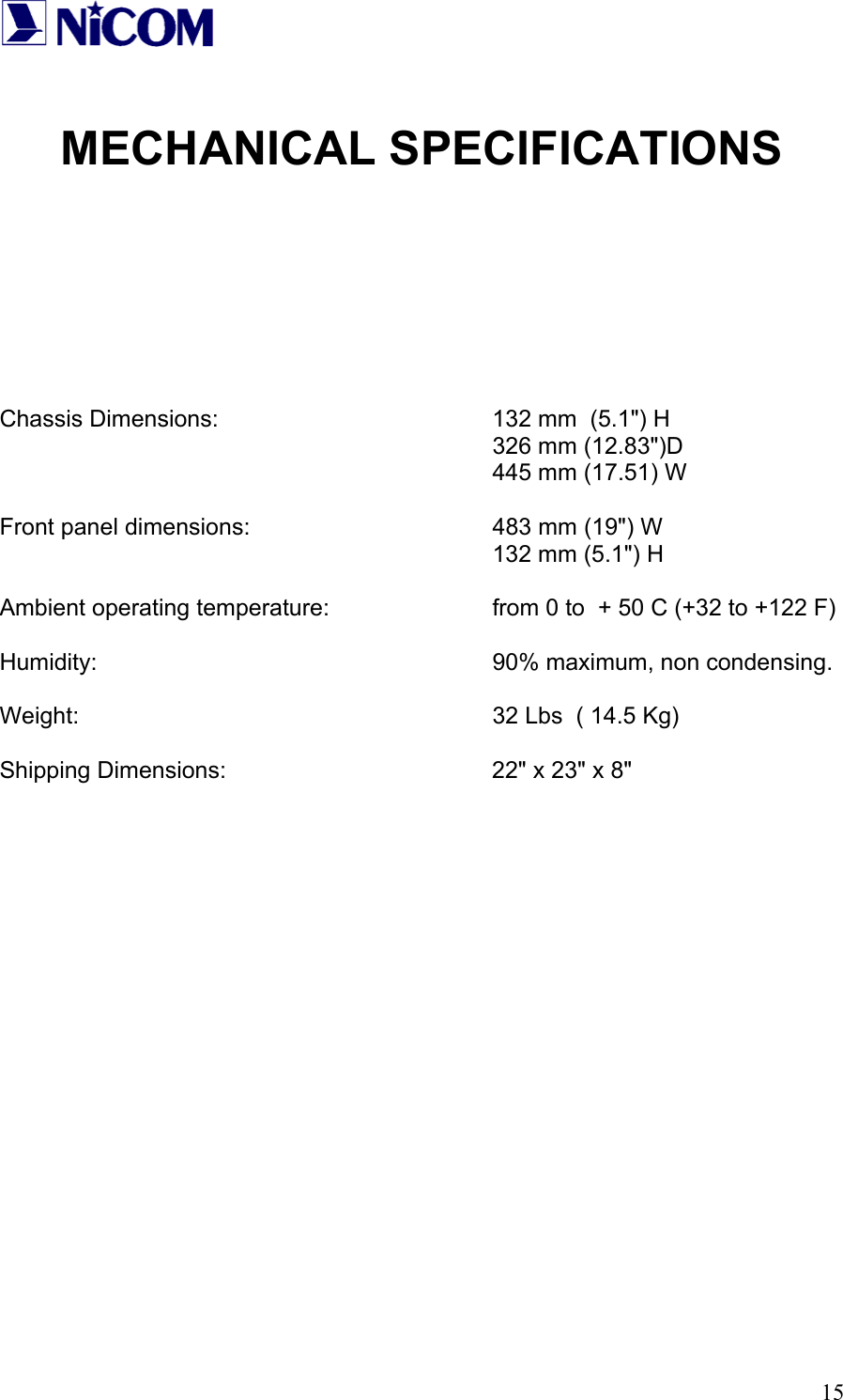
USERS MANUAL
Navigation menu
Upload a User Manual
Namespaces
Wiki Guide
HTML
PDF
Info
Views
User Manual
Discussion / Help
Navigation