NiCOM USA NT350FP07 350W TRANSMITTER User Manual NT350
NiCOM USA 350W TRANSMITTER NT350
USERS MANUAL

1
TABLE OF CONTENTS
CHAPTER 1
Transmitter General Description And Installation Procedures Page 2
Remote Control Feature Page 5
Analog telemetry Option Page 7
Programming the NT 350 Page 8
CHAPTER 2
Electrical Specifications Page 13
Mechanical Specifications Page 15
CHAPTER 3
350 W schematics and components list Page 16

2
CHAPTER 1
GENERAL DESCRIPTION
NT 350 Transmitter - Exciter
INTRODUCTION
The NT-350-LCD is a highly integrated broadband solid-state Mos-Fet FM
transmitter of 350W rated power, fitted in a 3 unit rack, which do not require any
specific calibration to operate in the 87.5 ÷ 108 MHz frequency range. The unit is
microprocessor controlled with an optional PC interface.
Its compact size, high efficiency, wide mains range acceptance, low
maintenance requirements and broadband construction, make this amplifier ideal
in medium power repeaters, in unattended posts and as a reserve.
Its sturdy, modular mechanical and electrical construction guarantees a high
MTBF and an easy maintenance. The modules are easily identifiable and
inspectable with few interconnections each with the other, through multi-pole
connectors.
The nominal RF output power is obtained over the full FM range is particularly
stable against time, temperature and frequency variations being ALC regulated,
with a front panel adjustment. The output power may be varied from a minimum
level to the nominal level and the frequency varied over the full FM range, without
retouching the drive power or any other adjustment than the ALC control.
The output stage has a reverse intermodulation figure, which is lower than
standard bipolar construction, due to the all Mos-Fet design and approaches that
of tube equipment.
A simple metering and alarm section completes the amplifier, permitting an
easy check of the functioning with few, unambiguous readings. The front panel
displays forward, reflected power and modulation measures. It is possible to
change the frequency of the unit from the front panel, password protected.
The whole assembly is designed in accordance with the CCIR, FCC and
tighter international norms and conforms to the recent, strict requirements for
EMI susceptance and emission.

3
INSTALLATION
After unpacking the unit, check for any mechanical damage or loose parts
inside. If there is any transportation damage, inform the supplier immediately
and do not put the module into operation.
The applicable voltage is 110 or 220v depending on how the unit was ordered.
Please check the back of the unit for the voltage that the unit was set to, and if it
is the wrong one, please call Nicom for instruction on how to set the voltage.
Ensure that the station’s ground system connections have a ground
resistance of less than 5 ohms. The equipment’s rack or cabinet must be
effectively grounded.
Check that the transmitter’s main switch is off.
Connect the power cord to the AC plug.
STARTING PROCEDURE
Connect the antenna cable to the ‘N’ type connector on the back of the unit.
The antenna system must be set up to operate at the transmitter’s working
frequency.
ATTENTION
Antenna matching is extremely crucial for FM transmitters. Operate this unit
only after verifying good matching. Mismatching will decrease the
communication distance and unduly stress the semiconductors.
Turn on the transmitter. You should see the "WAIT" message appear on the
LCD Display.
After few seconds the green LED “PLL LOCK” should turn on. This
indicates that the frequency is locked on the programmed value. In the display
will appear a sequence of squares.
After few more seconds the “RF ENABLE” green LED will come on. This
indicates that RF power is being delivered to the output connector on the back.
You can now increase the output power through the small trimpot located in the
front panel and identified with " RF ADJ."
Increase slowly till you reach the power you need; keep always an eye at the
Reflected power reading to verify that the antenna is well operating. The
indication of the reflected power is on the right side of the display "RFL".
Once you have reached the desired power level, you should wait till the unit
warms up (30 minutes)

4
Now you can input modulation. For MONO operation connect your signal to the
XLR connector or BNC, Depending on the model. Following the connecting
instructions printed on the back of the transmitter and then regulate the input
level with the apposite trimmer. For stereo input, use the BNC connector
labeled “MPX”.
Regulate the audio with the apposite trimmer.
Note:Be sure that the modulation level is close to but not more than 75KHz.
75KHz is 100% modulation. Lower modulation level will decrease the S/N value
while over-modulation (>100%) will cause distortion at the receiver and it is
against current regulations.

5
REMOTE CONTROL FEATURE
The NT 350 is equipped with a 9 pin RS 232 connector that allows all the mains
telemetry
functions. The software is supplied with the unit and with this CD rom it's
possible to monitor and to change the main parameters ot the NT 350 on the
computer's screen.
The NT 350 is also supplied with the interlock connector that allows to switch the
power on and
off simply by grounding the inner conductor of the BNC.
NOTE:
The CD (optional) contains the remote control software of the NT 350. If a
CD was not ordered, please check Nicom website (www.NicomUsa.com)
where the latest version of the software is available for download.
REMOTE CONTROL SOFTWARE
INSTALLATION
The NT 350 comes with a Serial port RS 232. This port allows a Bi-Directional
remote control of the unit from a PC.
INSTALLING THE SOFTWARE
1. Insert the NT 350 CD-ROM into the CD drive.
2. Run Setup.exe file found in the main folder of the CD-ROM. The installation
will continue automatically asking only for the name of the folder of the hard
drive where the program will be installed. It will be necessary to reboot the
computer.
3. Once installed, the Tx_Nicom program icon can be recalled by clicking : Start
- Programs - Tx_Nicom icon.
CONNECTING THE NT 350
The NT 350 is equipped with a Serial Port (RS232) in the rear panel. To connect
the computer with the NT 350 we recommend standard serial cables Pin-to-Pin;
the length of the cable must stay within 60 feet.

6
REMEMBER TO CLOSE THE PROGRAM BEFORE REMOVING THE
CONNECTING CABLE
RUNNING THE PROGRAM
Once the program is running, from the main screen it is necessary to click the
POWER ON button; the screen will light up and a message" COMMUNICATION
IN PROGRESS" will appear. After few seconds, on the left side of the screen,
the operating frequency will appear together with all the other parameters. If not,
check the Communication port setting (COM1-COM 2).
To change it, click the File menu and then select "set Port".
The other parameters shown on the screen are the following:
1. Temperature in Celsius ( remember that Farheneit is Celsius x 1.8 + 20)
2. Lock Indicator showing that PLL circuit of the unit is locked
3. On the Air showing that the unit is transmitting
4. RF Forward giving the amount of Watts radiated
5. RF Reflected giving the amount of reflected power
On the right side of the screen there are four buttons that allow to modify the
parameters:
a. Send Button to be used after a change of frequency is made
b. Set Frequency allows the change of frequency by clicking the new
frequency on
the keyboard on the left side of the screen
c. Disconnect allows to disconnect the system
d. RF On turns up and down the power
7
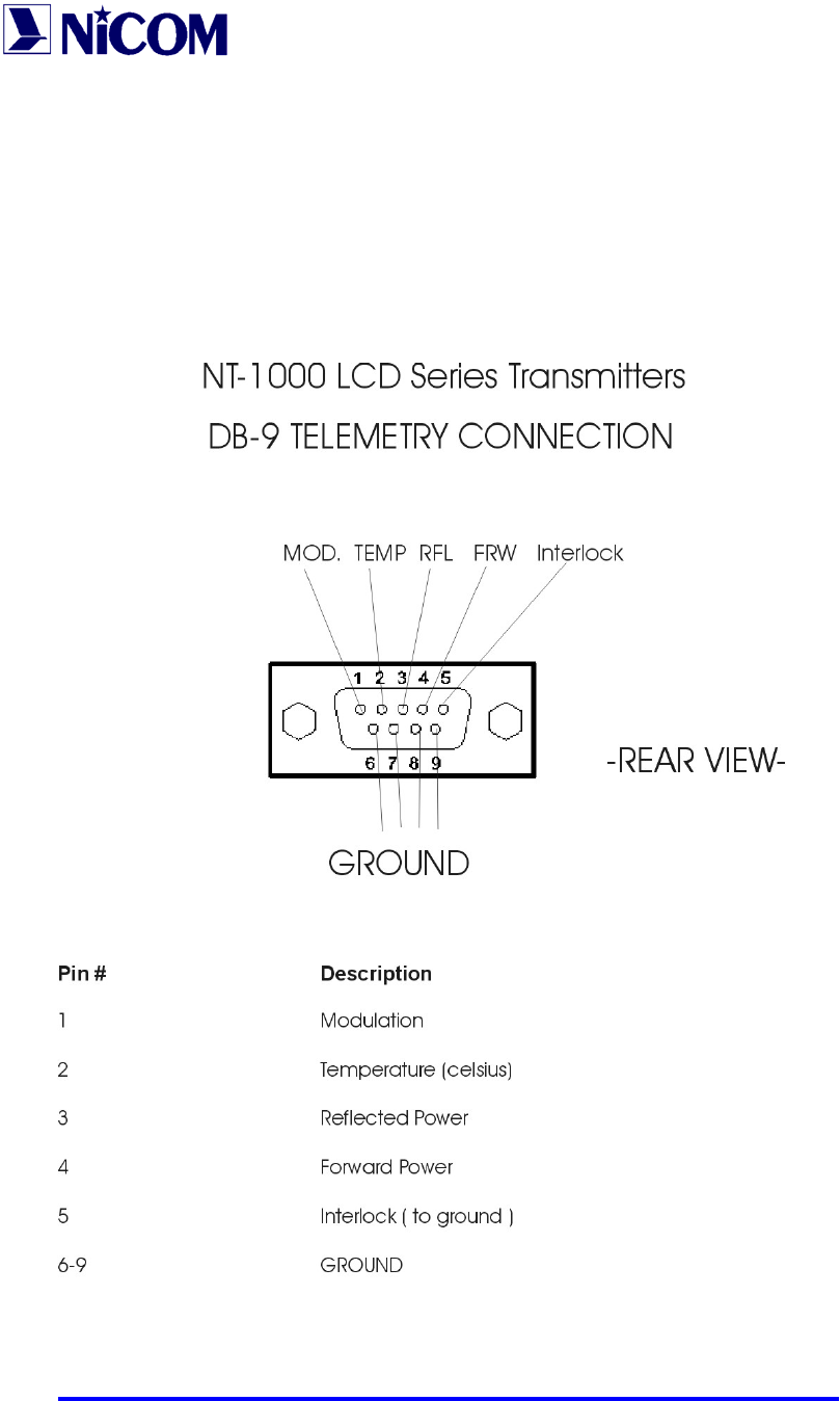
An Analog telemetry option is available for installation as an option, to be
specified at time of purchase. Below is a diagram of the connections on the
RS232 port.
NOTE: IF THE ANALOG TELEMETRY OPTION IS SELECTED AT TIME OF
PURCHASE, THE REMOTE CONTROL SOFTWARE DESCRIBED BELOW
WILL NOT WORK.
8
NT 350 PROGRAMMING
Connect a 50 ohm load or 50 ohm antenna to the RF output, connect the equipment into
a mains supply (120 or 240 VAC). The equipment is factory pre-set to 50 W.
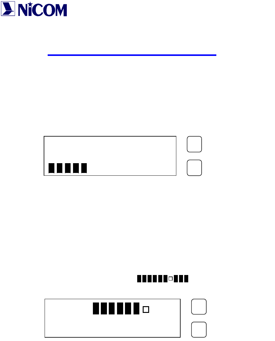
Switch ON the power and the yellow V POWER LED will light.
The Display will show:
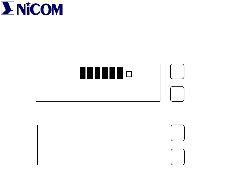
After 3 seconds the green PLL LOCK led will light and the Display will show an
increasing bar. After a further 5 seconds the green ENABLE will light and there will be
output power.
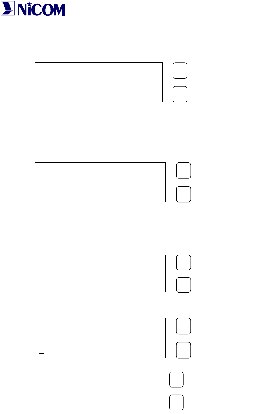
At this point the Display will show the next parameter:
• Level Modulation (MOD >
• Forward Power (FRW 50.0W);
• Reflected Power (RFL 0.4W).
The default frequency is 98.000 MHz.
To display the frequency push the SETTING key.
In order to display the parameter push the SELECT key.
WAIT
PROGRAM
SETTING
MOD >
PW 50W PR 0.4W
PROGRAM
SETTI
NG

9
Display Password
The Password mode is factory set to enable, and is not possible change this setting.
The default password is 1 2 3.
The way for changing the password is the following:
• Press the PROGRAM key for 3 seconds;
• Press the PROGRAM key to move the underscore character position at the required
digit, and press the SETTING key to confirm the digit.
Repeat the same for the two remaining digits.
• If the password is correct press the SETTING key to confirm, otherwise press the
PROGRAM key to select again.
PASSWORD
0 1 2 3 4 5 6 7 8 9
PROGRAM
SETTING
PASSWORD
0 1 2 3 4 5 6 7 8 9
PROGRAM
SETTING
*
PASSWORD
0 1 2 3 4 5 6 7 8 9
PROGRAM
SETTING
***
CONFIRM (Y/N) ?
N=SEL. Y=SET.
PROGRAM
SETTING
10
If the password is not correct an error is displayed:
After a few seconds the display will show the parameters again.
When the password is correct, the display will show:
To change the password press the SETTING key.
To change the frequency press the PROGRAM key.
• For changing the password proceed with the same method for the required
password:
The confirmation password will be required.
If the password is correct the display will show:
NEW PASS . = SET.
NEW FREQ . = PRG .
PROGRAM
SETTING
ERROR
PASSWORD
PROGRAM
SETTING
NEW PASSWORD
0 1 2 3 4 5 6 7 8 9
PROGRAM
SETTING
CONFIRMATION
0 1 2 3 4 5 6 7 8 9
PROGRAM
SETTING
STORED
NEW PASSWORD
PROGRAM
SETTING

11
If the confirmation password is wrong the display will show:
IMPORTANT NOTE
! BE CAREFUL !
Once the password is set, it must be remembered, otherwise neither the
frequency nor the password can be reset and the unit will have to be returned to
Nicom for resetting.
Display Change of Frequency.
• Press the PROGRAM key for 3 seconds and enter the correct password. At this point
press again the SELECT key:
• Press the PROGRAM key to change the desired digit and press the SETTING key to
confirm it.
The underscore character indicates which digit can be change.
To move the underscore character hit the PROGRAM key.
ERROR
CONFIRMATION
PROGRAM
SETTING
NEW PASS . = SET.
NEW FREQ . = PRG .
PROGRAM
SETTING
FREQUENCY ?
MHz 103.900
PROGRAM
SETTING
12
When the new frequency is chosen, then press the SETTING key confirm it.
After a “WAIT CYCLE”, the display will show the parameters:
After 7 minutes the display light will switch off and the display will show:
MOD >
PW 1000W PR 0.4W
PROGRAM
SETTING
NICOM
MHz 103.900
PROGRAM
SETTING

13
CHAPTER 2
ELECTRICAL SPECIFICATIONS
NT 350 TECHNICAL DATA
Power output: 5 to 350 Watts continuously variable
Frequency of operation: Sinthesized with TXCO crystal
reference
RF output connector/ Impedance: N Type / 50 Ohms
Frequency Stability: Better than 5ppm (
±
500 Hz) , 0 to
50° C.
Frequency Range: 87.5 - 108 Mhz
Frequency programming: Digitally in 10 Khz increments.
Modulation type: Direct FM at the carrier frequency
S/N Ratio (ref. to 50 Khz / 1000 Hz): Mono > 70dB - Stereo > 65 dB.
Distortion, THD: < 0.1 %, Typ. 0.05 %
Asyncronous AM S/N ratio: 65 dB below reference carrier with
100% AM
modulation, 75 or 50 usec de-
emphasis (no FM
modulation present).
Syncronous AM S/N ratio: 60 dB below reference carrier with
100% AM
modulation (FM modulation
±
75
Khz).
DC input power: 48 V VDC 12 A
AC input power: 110-240 V (internally selectable)
Ambient Temperature Range: 0° to 50° C (+32° to +122° F)
Spurious and Harmonic or
Subharmonic Emissions: < -80 dB or better
Stereo Separation 55 dB @ 1 Khz
COMPOSITE OPERATION
Composite inputs four total, 1 for MPX and 3 for
SCA
MPX input 1 unbalanced bnc connector
MPX input impedance 2 K ohms
MPX input level 3,5 V p-p (1,237 Vrms/3.64 dBm)
Composite FM unweighed S/N ratio > 78 dB below
±
75 Khz
deviation at 400 Hz

14
measured in a 30 Hz - 100Khz
bandwidth with
75 usec de-emphasis (RMS)
Composite Total Harmonic Distortion 0.05 % typical
Composite Intermodulation Distortion 0.05 %, measured with a 1 Khz
and a 1.3 Khz
tone, 1:1 ratio, at 100% modulation
Baseband 30 Hz - 60 Khz within 0.15 dB
Crosstalk main to stereo subchannel and
stereo subchannel
to main > 55 dB ( 60 dB typical)
SCA Inputs 3 unbalanced BNC connectors
SCA Input Impedance 10 K Ohms
SCA Input Levels 0 dBm (775 mV rms/ 2.2 V p-p)
nominal for
±
75 Khz deviation, adjustable
SCA Amplitude Response
±
0.8 dB, 40 Khz to 100 Khz
Crosstalk 67 Khz SCA to main or to stereo
subchannel >65dB
92 Khz SCA to main or to stereo
subchannel >70 dB
MONOAURAL OPERATION
Audio Connector XLR
Audio Input Impedance 600 Ohms balanced or unbalanced;
50 dB common
mode suppression
Audio Input Level 0 dBm (775 mV rms/ 2.2 V p-p)
nominal for
±
75 Khz deviation, adjustable
FM S/N Ratio > 70 dB below
±
75 Khz
deviation at 400 Hz
measured in a 30 Hz - 20Khz
bandwidth with
75 usec de-emphasis (RMS)
Audio Frequency Response
±
0.8 dB, 30 Hz to 15 Khz
Intermodulation Distortion 0.05 %, measured with a 1 Khz
and a 1.3 Khz
tone, 1:1 ratio, at 100% modulation

15
MECHANICAL SPECIFICATIONS
Chassis Dimensions: 132 mm (5.1") H
326 mm (12.83")D
445 mm (17.51) W
Front panel dimensions: 483 mm (19") W
132 mm (5.1") H
Ambient operating temperature: from 0 to + 50 C (+32 to +122 F)
Humidity: 90% maximum, non condensing.
Weight: 32 Lbs ( 14.5 Kg)
Shipping Dimensions: 22" x 23" x 8"