Nihon Kohden ZM-540PA Medical Telemetry Transmitter User Manual OM ZM 540 541PA
Nihon Kohden Corporation Medical Telemetry Transmitter OM ZM 540 541PA
UserManual.wiki
>
Nihon Kohden
>
ZM 540PA User Manual
Users Manual
Navigation menu
Upload a User Manual
Namespaces
Wiki Guide
HTML
PDF
Info
Views
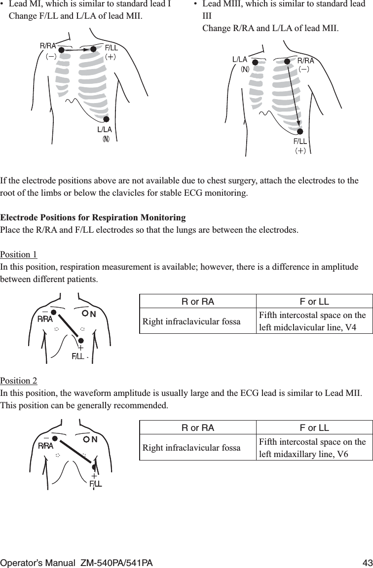
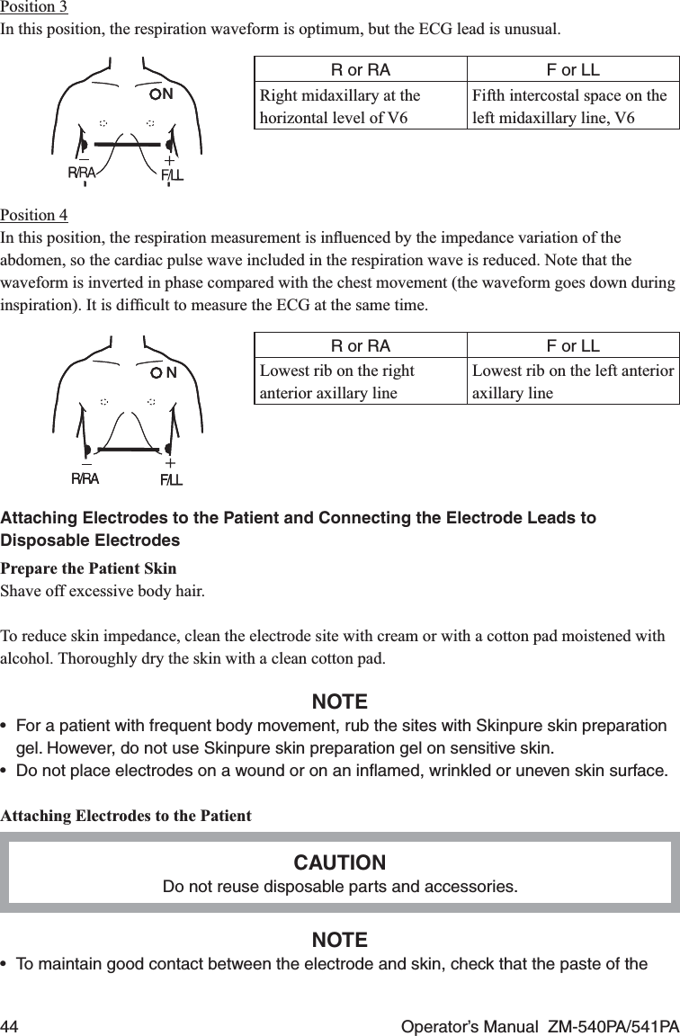
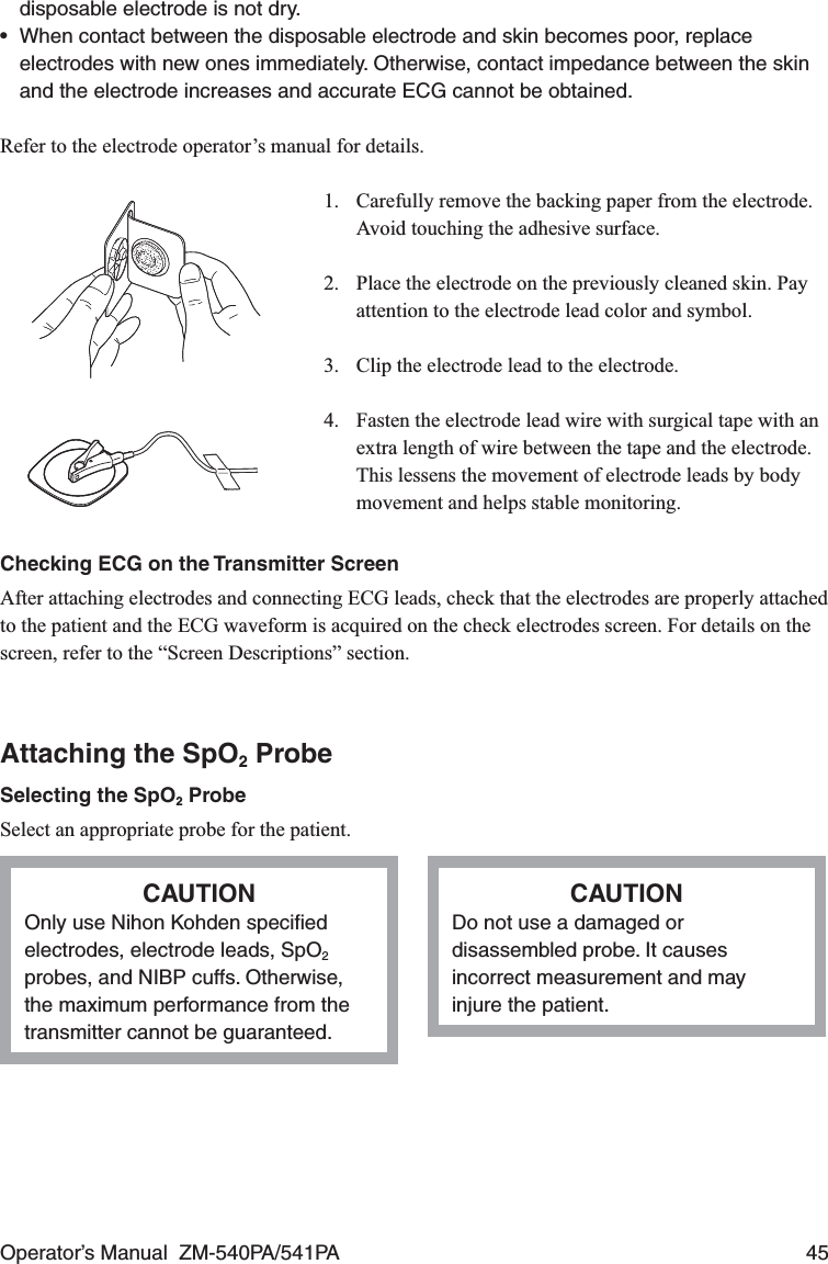
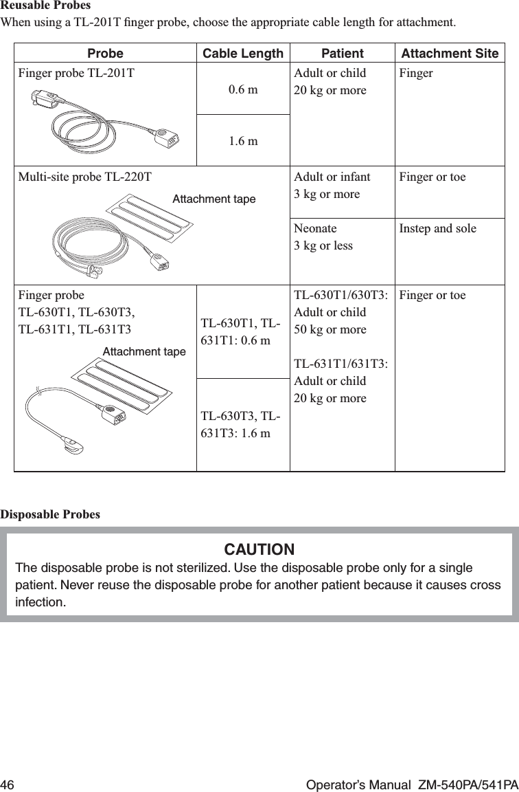
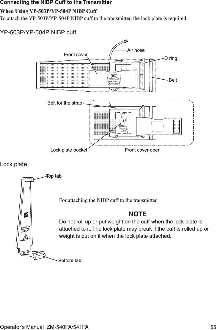
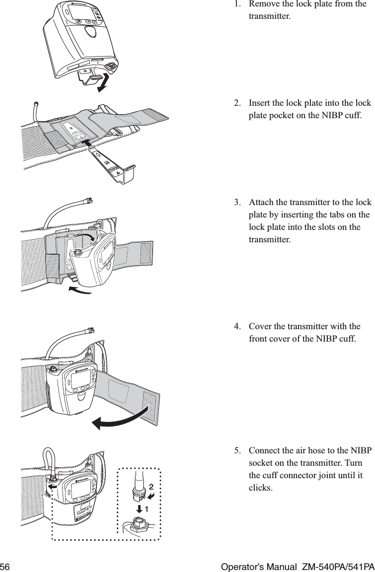
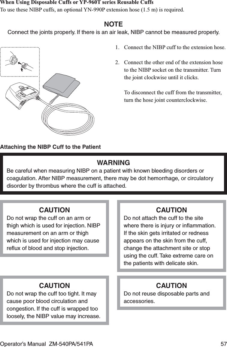
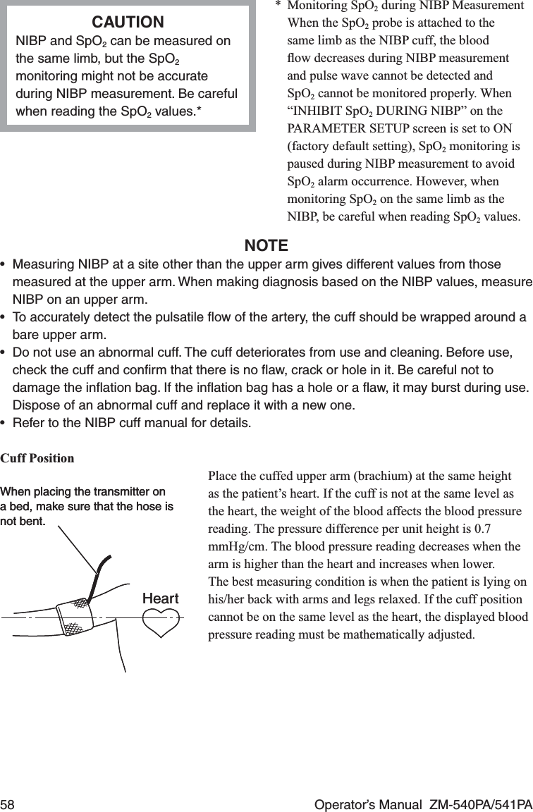
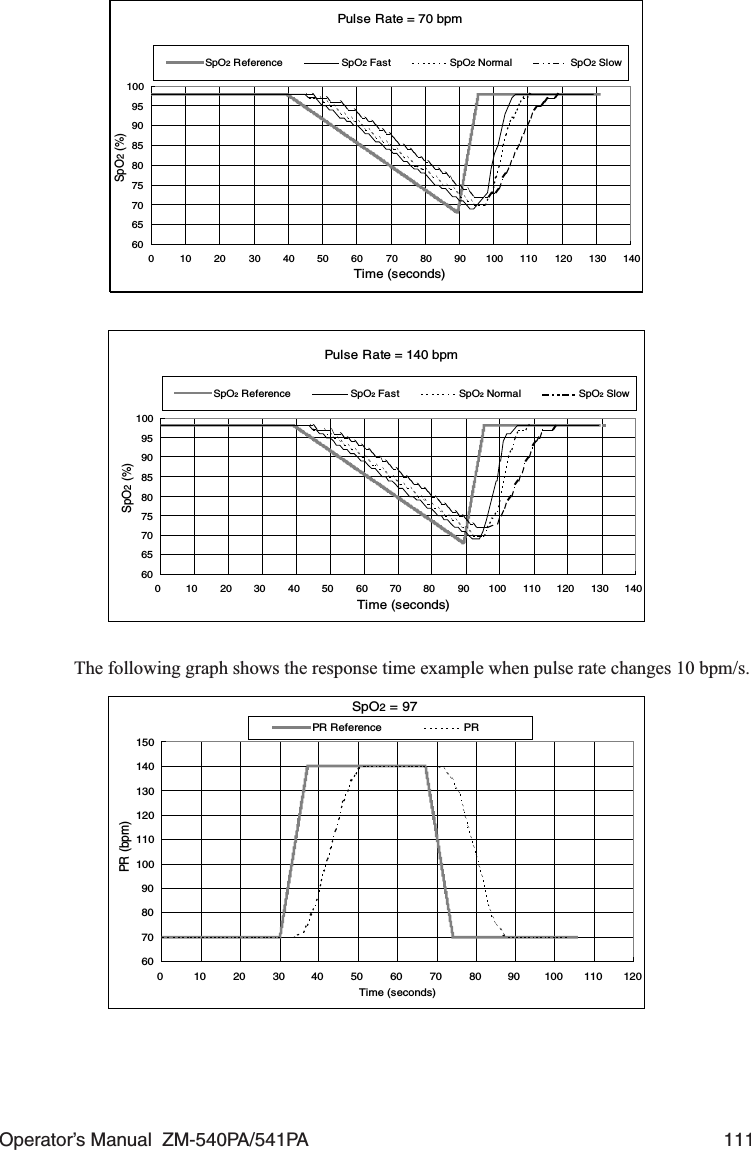
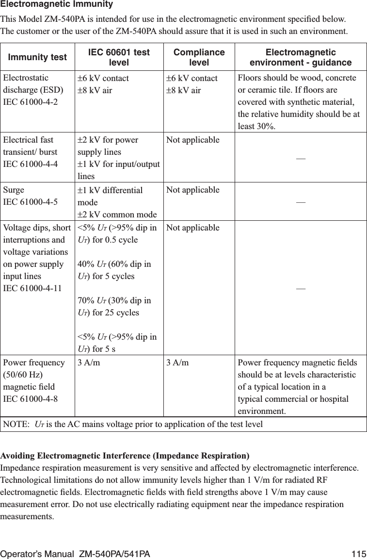
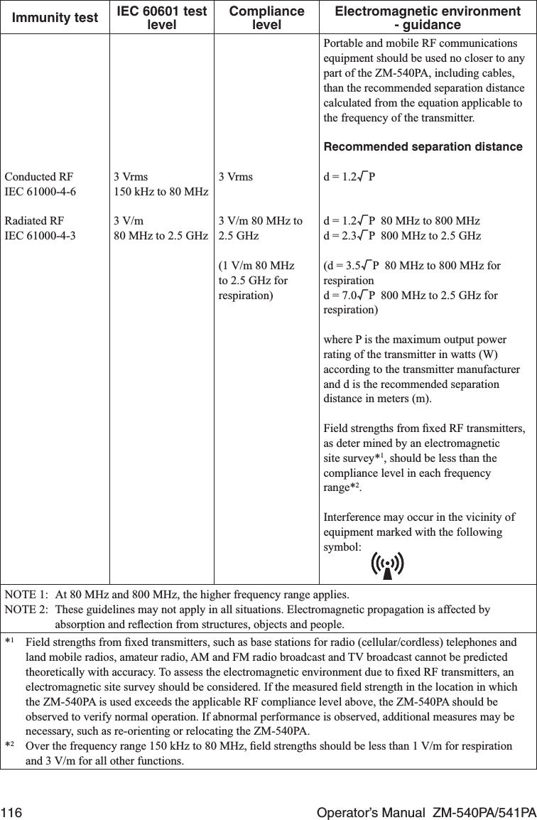
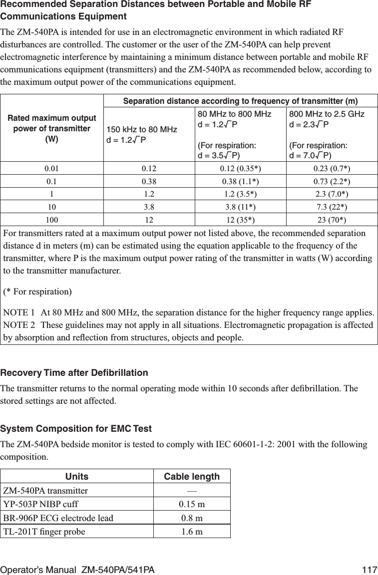
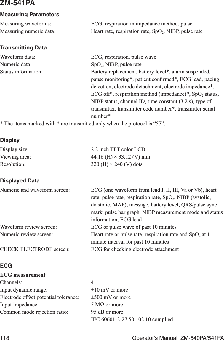
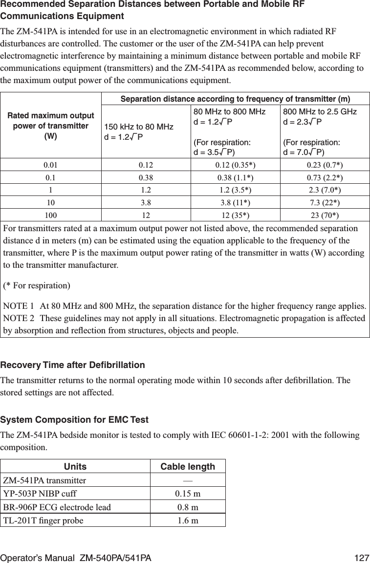
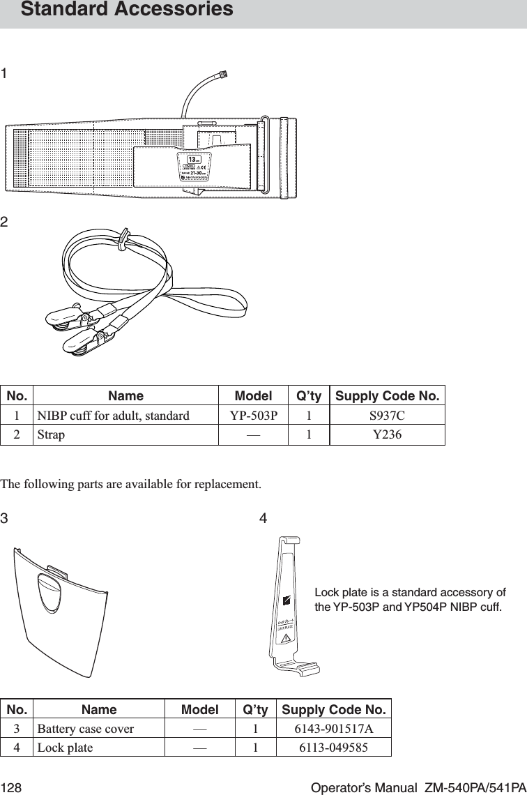
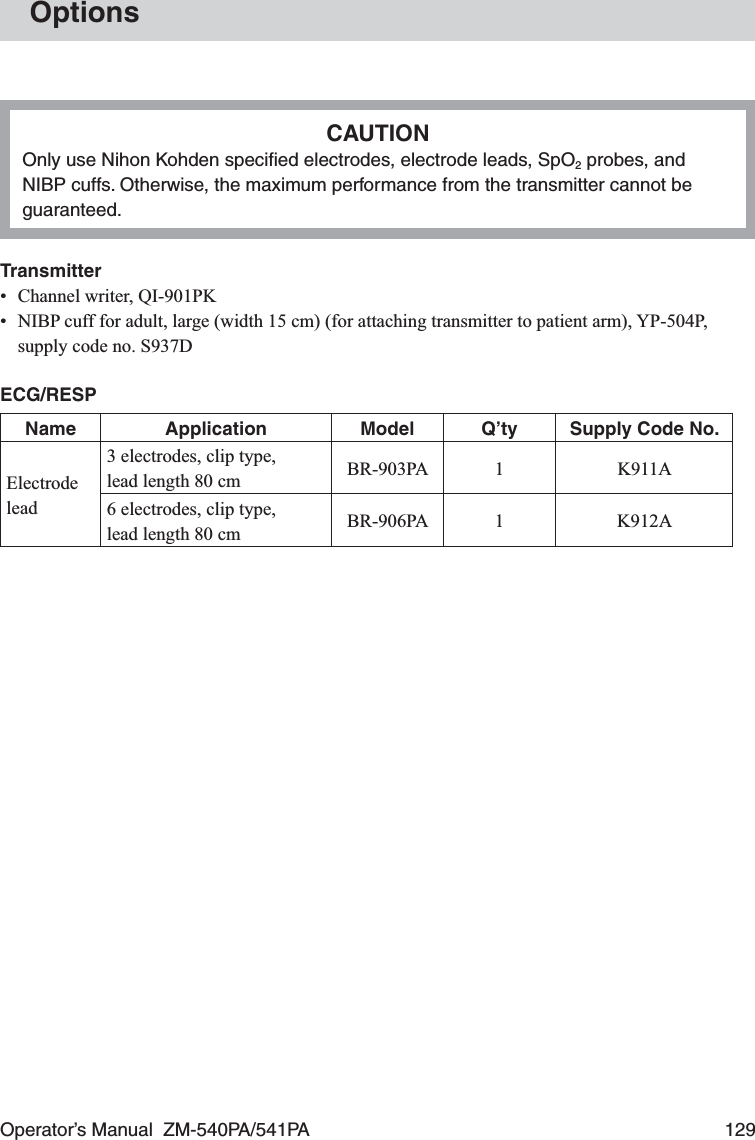
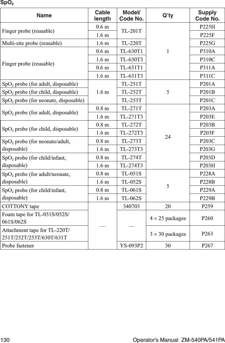
User Manual
Discussion / Help
Navigation