Nihon Kohden ZM-540PA Medical Telemetry Transmitter User Manual OM ZM 540 541PA
Nihon Kohden Corporation Medical Telemetry Transmitter OM ZM 540 541PA
Users Manual
If you have any comments or suggestions on this
manual, please contact us at:
www.nihonkohden.com
Transmitter
ZM-540PA/ZM-541PA
0614-902754
Copyright Notice
The entire contents of this manual are copyrighted by Nihon Kohden. All rights are reserved. No part
of this document may be reproduced, stored, or transmitted in any form or by any means (electronic,
mechanical, photocopied, recorded, or otherwise) without the prior written permission of Nihon
Kohden.
Operator’s Manual ZM-540PA/541PA i
GENERAL HANDLING PRECAUTIONS
This device is intended for use only by qualified medical personnel.
Use only Nihon Kohden approved products with this device. Use of non-approved
products or in a non-approved manner may affect the performance specifications
of the device. This includes, but is not limited to, batteries, recording paper, pens,
extension cables, electrode leads, input boxes and AC power.
Please read these precautions thoroughly before attempting to operate the instrument.
1. To safely and effectively use the instrument, its operation must be fully understood.
2. When installing or storing the instrument, take the following precautions:
(1) Avoid moisture or contact with water, extreme atmospheric pressure, excessive humidity and
temperatures, poorly ventilated areas, and dust, saline or sulphuric air.
(2) Place the instrument on an even, level floor. Avoid vibration and mechanical shock, even
during transport.
(3) Avoid placing in an area where chemicals are stored or where there is danger of gas leakage.
(4) The power line source to be applied to the instrument must correspond in frequency and
voltage to product specifications, and have sufficient current capacity.
(5) Choose a room where a proper grounding facility is available.
3. Before Operation
(1) Check that the instrument is in perfect operating order.
(2) Check that the instrument is grounded properly.
(3) Check that all cords are connected properly.
(4) Pay extra attention when the instrument is in combination with other instruments to avoid
misdiagnosis or other problems.
(5) All circuitry used for direct patient connection must be doubly checked.
(6) Check that battery level is acceptable and battery condition is good when using
batteryoperated models.
4. During Operation
(1) Both the instrument and the patient must receive continual, careful attention.
(2) Turn power off or remove electrodes and/or transducers when necessary to assure the
patient’s safety.
(3) Avoid direct contact between the instrument housing and the patient.
5. To Shutdown After Use
(1) Turn power off with all controls returned to their original positions.
(2) Remove the cords gently; do not use force to remove them.
(3) Clean the instrument together with all accessories for their next use.
ii Operator’s Manual ZM-540PA/541PA
6. The instrument must receive expert, professional attention for maintenance and repairs.
When the instrument is not functioning properly, it should be clearly marked to avoid
operation while it is out of order.
7. The instrument must not be altered or modified in any way.
8. Maintenance and Inspection
(1) The instrument and parts must undergo regular maintenance inspection at least every 6
months.
(2) If stored for extended periods without being used, make sure prior to operation that the
instrument is in perfect operating condition.
(3) Technical information such as parts list, descriptions, calibration instructions or other
information is available for qualified user technical personnel upon request from your Nihon
Kohden representative.
9. When the instrument is used with an electrosurgical instrument, pay careful attention to
the application and/or location of electrodes and/or transducers to avoid possible burn to
the patient.
10. When the instrument is used with a defibrillator, make sure that the instrument is
protected against defibrillator discharge. If not, remove patient cables and/or transducers
from the instrument to avoid possible damage.

Operator’s Manual ZM-540PA/541PA iii
WARRANTY POLICY
Nihon Kohden Corporation (NKC) shall warrant its products against all defects in materials and
workmanship for one year from the date of delivery. However, consumable materials such as
recording paper, ink, stylus and battery are excluded from the warranty.
NKC or its authorized agents will repair or replace any products which prove to be defective during
the warranty period, provided these products are used as prescribed by the operating instructions
given in the operator’s and service manuals.
No other party is authorized to make any warranty or assume liability for NKC’s products.
NKC will not recognize any other warranty, either implied or in writing. In addition, service,
technical modification or any other product change performed by someone other than NKC or its
authorized agents without prior consent of NKC may be cause for voiding this warranty.
Defective products or parts must be returned to NKC or its authorized agents, along with an
explanation of the failure. Shipping costs must be pre-paid.
This warranty does not apply to products that have been modified, disassembled, reinstalled or
repaired without Nihon Kohden approval or which have been subjected to neglect or accident,
damage due to accident, fire, lightning, vandalism, water or other casualty, improper installation or
application, or on which the original identification marks have been removed.
In the USA and Canada other warranty policies may apply.
CAUTION
United States law restricts this product to sale by or on the order of a physician.

iv Operator’s Manual ZM-540PA/541PA
Equipment Authorization Requirement
This device complies with Part 15 of the FCC (Federal Communications Commission) Rules.
Operation is subject to the following two conditions:
(1) this device may not cause harmful interference, and
(2) this device must accept any interference received, including interference that may cause
undesired operation.
This device complies with Part 95 Subpart H of the FCC Rules to be used in wireless medical
telemetry service.
Operation of this equipment requires the prior coordination with a frequency coordinator designated
by FCC for the Wireless Medical Telemetry Service.
CAUTION
To comply with the FCC radio frequency (RF) exposure compliance requirements, no
change to the antenna or the device is permitted. Any change to the antenna or the
device could result in the device, exceeding the RF exposure requirements and void
user’s authority to operate this device.
NOTE
• Use this device only indoors.
• This device has been tested and complies with FCC radiation exposure limits set forth
for an uncontrolled environment. The RF transmission power from the antenna conforms
to the general public FCC RF Exposure Guidelines in Supplement C to OET65 limit of
Specific Absorption Rate (SAR) 1.6 W/kg. The maximum SAR value measured from this
device was extremely smaller than 1.6 W/kg. This device must not be located together
with or operated in conjunction with any other unspecified antenna or transmitter.
• The devices require registration and deployment by an authorized frequency coordinator.
The ASHE (American Society for Healthcare Engineering) has been designated by the
FCC to manage the WMTS frequencies. This device has frequency bands which may
not be used in some areas. For details, contact your Nihon Kohden representative. For
details on the guidelines, refer to the ASHE home page.

Operator’s Manual ZM-540PA/541PA v
EMC RELATED CAUTION
This equipment and/or system complies with IEC 60601-2 International Standard for
electromagnetic compatibility for medical electrical equipment and/or system.
However, an electromagnetic environment that exceeds the limits or levels stipulated
in IEC 60601-1-2, can cause harmful interference to the equipment and/or system or
cause the equipment and/or system to fail to perform its intended function or degrade
its intended performance. Therefore, during the operation of the equipment and/or
system, if there is any undesired deviation from its intended operational performance,
you must avoid, identify and resolve the adverse electromagnetic effect before
continuing to use the equipment and/or system.
The following describes some common interference sources and remedial actions:
1. Strong electromagnetic interference from a nearby emitter source such as an
authorized radio station or cellular phone:
Install the equipment and/or system at another location. Keep the emitter source
such as cellular phone away from the equipment and/or system, or turn off the
cellular phone.
2. Radio-frequency interference from other equipment through the AC power supply of
the equipment and/or system:
Identify the cause of this interference and if possible remove this interference
source. If this is not possible, use a different power supply.
3. Effect of direct or indirect electrostatic discharge:
Make sure all users and patients in contact with the equipment and/or system are
free from direct or indirect electrostatic energy before using it. A humid room can
help lessen this problem.
4. Electromagnetic interference with any radio wave receiver such as radio or
television:
If the equipment and/or system interferes with any radio wave receiver, locate the
equipment and/or system as far as possible from the radio wave receiver.
5. Interference of lightning:
When lightning occurs near the location where the equipment and/or system is
installed, it may induce an excessive voltage in the equipment and/or system.
In such a case, disconnect the AC power cord from the equipment and/or
system and operate the equipment and/or system by battery power, or use an
uninterruptible power supply.

vi Operator’s Manual ZM-540PA/541PA
6. Use with other equipment:
When the equipment and/or system is adjacent to or stacked with other equipment,
the equipment and/or system may affect the other equipment. Before use, check
that the equipment and/or system operates normally with the other equipment.
7. Use of unspecified accessory, transducer and/or cable:
When an unspecified accessory, transducer and/or cable is connected to this
equipment and/or system, it may cause increased electromagnetic emission
or decreased electromagnetic immunity. The specified configuration of this
equipment and/or system complies with the electromagnetic requirements with the
specified configuration. Only use this equipment and/or system with the specified
configuration.
8. Use of unspecified configuration:
When the equipment and/or system is used with the unspecified system
configuration different than the configuration of EMC testing, it may cause
increased electromagnetic emission or decreased electromagnetic immunity.
Only use this equipment and/or system with the specified configuration.
9. Measurement with excessive sensitivity:
The equipment and/or system is designed to measure bioelectrical signals with
a specified sensitivity. If the equipment and/or system is used with excessive
sensitivity, artifact may appear by electromagnetic interference and this may
cause mis-diagnosis. When unexpected artifact appears, inspect the surrounding
electromagnetic conditions and remove this artifact source.
If the above suggested remedial actions do not solve the problem, consult your Nihon
Kohden representative for additional suggestions.

Operator’s Manual ZM-540PA/541PA vii
Conventions Used in this Manual and Instrument
Warnings, Cautions and Notes
Warnings, cautions and notes are used in this manual to alert or signal the reader to specific
information.
WARNING
A warning alerts the user to the possible injury or death associated with the use or
misuse of the instrument.
CAUTION
A caution alerts the user to possible injury or problems with the instrument associated
with its use or misuse such as instrument malfunction, instrument failure, damage to
the instrument, or damage to other property.
NOTE
A note provides specific information, in the form of recommendations, prerequirements,
alternative methods or supplemental information.
viii Operator’s Manual ZM-540PA/541PA
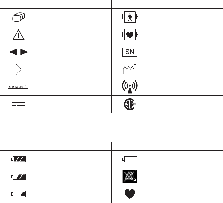
Explanations of the Symbols in this Manual and Instrument
The following symbols found in this manual/instrument bear the respective descriptions as given.
On Panel
Symbol Description Symbol Description
Change screen Defibrillation proof type BF
applied part
Attention, consult operator’s
manual
Defibrillation proof type CF
applied part
Moves cursor, scrolls data Serial number
Direction for attaching battery
cover Year of manufacture
Direction for inserting battery RF transmitter
Non-ionizing radiation
Direct current CSA mark
On LCD
Symbol Description Symbol Description
Full battery Battery very weak
Replace battery
Battery 2/3 full Alarm suspended
Low battery
NIBP cannot be measured QRS/pulse sync mark

Operator’s Manual ZM-540PA/541PA 1
Intended Use
General
The ZM-540PA and ZM-541PA transmitter transmits ECG, respiration and pulse waveforms, SpO2
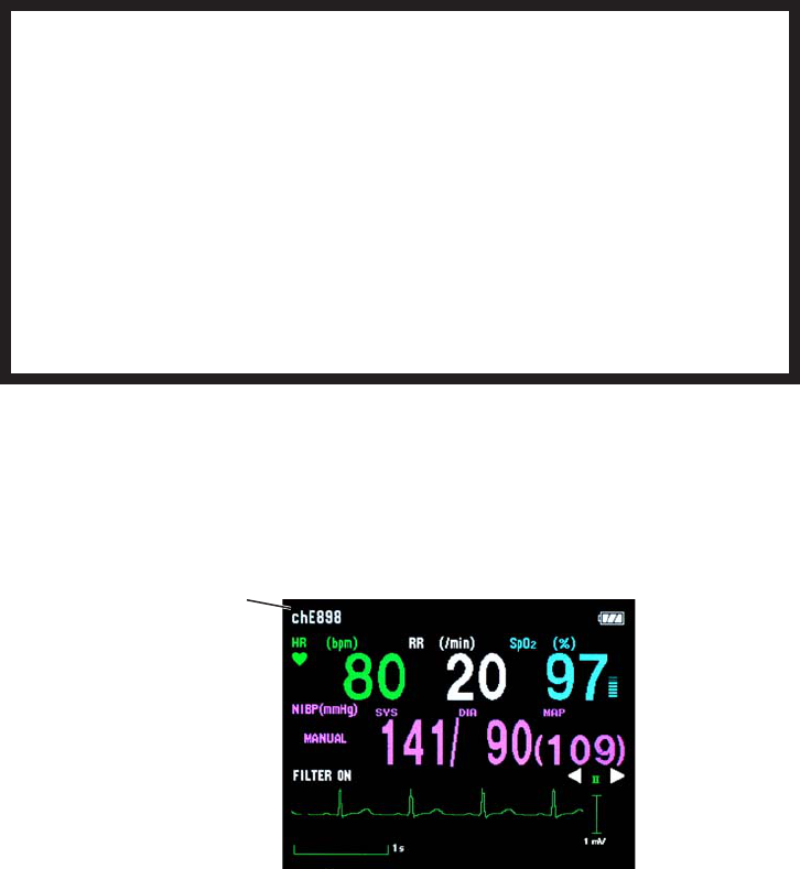
and NIBP data from a patient to a Nihon Kohden monitor for continuous monitoring. The front LCD
displays ECG (or pulse wave), numeric values of monitoring parameters, NIBP measuring mode and
interval, messages and battery condition.* It also displays the compressed waveform and numeric
data of the latest 10 minutes.
* Essential performance of this transmitter.
The difference between the ZM-540PA and ZM-541PA is the transmission frequency range.
ZM-540PA: 608.0250 MHz (channel number 9002) to 613.9750 MHz (channel number 9478)
ZM-541PA: 1395.0250 MHz (channel number E002) to 1399.9750 MHz (channel number E398)
1427.0250 MHz (channel number E502) to 1431.9750 MHz (channel number E898)
The transmitter channel can be changed with a QI-901PK channel writer.
Read the operator’s manual for the receiving monitor together with this manual before use.
WARNING
Do not use the same transmitter on more than one patient at the same time. Do not
connect different sensors on different patients to the same transmitter.
CAUTION
• Do not use the same channel for different patients. If the same channel is used
for two patients, the two patients’ data will be lost due to mutual modulation
interference, or another patient’s data may appear on the receiving monitor screen.
• Do not use two transmitters with adjacent channels in the same hospital. If
transmitters with adjacent channels are used, their radio waves interfere with each
other.
CAUTION
Be aware that signal loss and artifact may occur because of the multipath
cancellation* when using a transmitter.
* Multipath Cancellation (Standing Wave Interference)
When a radio wave reflects off a surface, there may be some points in the room where the
2 Operator’s Manual ZM-540PA/541PA
reflected and direct waves are exactly out of phase. At these points in the room, the reflected
and direct waves cancel each other out so that the signal strength is 0. This is called “multipath
cancellation” or “standing wave interference”. Locations where signal loss occurs are called “null
spots”. If the transmitter is moving or nearby people or objects are moving, null spots can occur
anytime and anywhere.
NOTE
• To prevent interference between channels, assign a channel administrator in the hospital
and only he or she should manage channel assignment.
• Use Nihon Kohden parts and accessories to assure maximum performance from your
instrument.
• For stable signal reception, it is recommended to use a diversity antenna system on the
receiving monitor. Otherwise, spike noise from transient fading of electric field strength
(for example, people moving) may interfere with the transmitter signal and may be
mistaken as an arrhythmia on the receiving monitor.
• For details on antennas and antenna construction, contact your Nihon Kohden
representative. You can also refer to the Telemetry System Installation Guide.
• Do not diagnose a patient based on only part of the monitoring data on the transmitter or
only on the data acquired by the transmitter. Overall judgment must be performed by a
physician who understands the features, limitations and characteristics of the transmitter
by reading this operator’s manual thoroughly and by reading the biomedical signals
acquired by other instruments.
Receiving Monitor
Any Nihon Kohden receiving monitor (central monitor with multiple patient receiver) can receive
signals from this transmitter as long as the protocol version and channel setting are the same on the
receiving monitor and transmitter.
NOTE
• For details on the receiving monitor and upgrade information, contact your Nihon Kohden
representative.
• The transmitter does not give any patient alarm, only a “no battery” alarm. Patient alarms
must be managed on the receiving monitor.
Operator’s Manual ZM-540PA/541PA 3
Panel Description
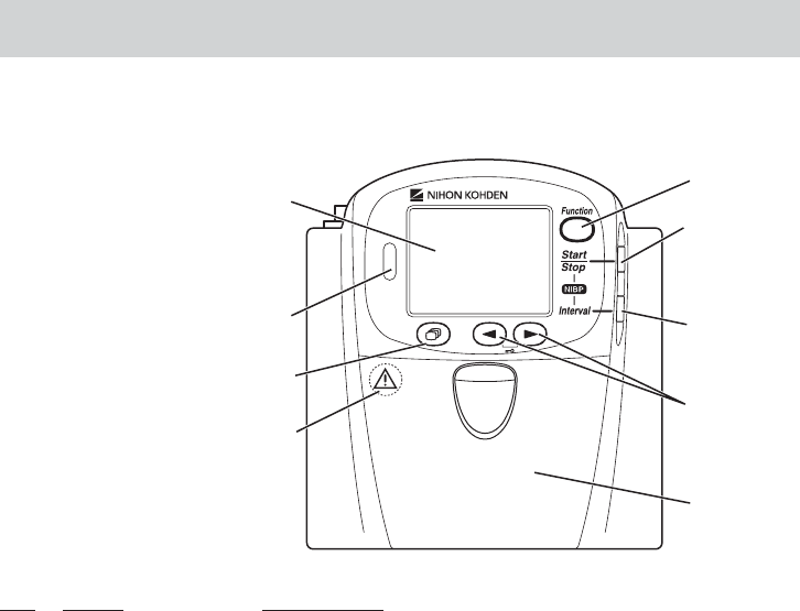
Front Panel
1
2
3
4
5
6
7
8
Refer to the WARNING
on the next page.
No. Name Description
1 LCD Displays numeric values, ECG or pulse wave, NIBP measuring
mode and interval, messages and battery status. For details, refer to
the “Screen Descriptions” section.
2 Infrared receiver Used for upgrading the transmitter software.
3 Screen key Toggles the screen in the following order.
After power on: Start up → Check electrodes → Numeric and
waveform → Waveform review → Numeric review → Display off
→ Check electrodes …
After auto display off: Numeric and waveform → Waveform
review → Numeric review → Display off → Check electrodes →
Numeric and waveform …
On a SETUP or CHECK screen, this key cancels changing setting
or exits the screen.
4 Operator’s Manual ZM-540PA/541PA
1
2
3
4
5
6
7
8
Refer to the WARNING
below.
No. Name Description
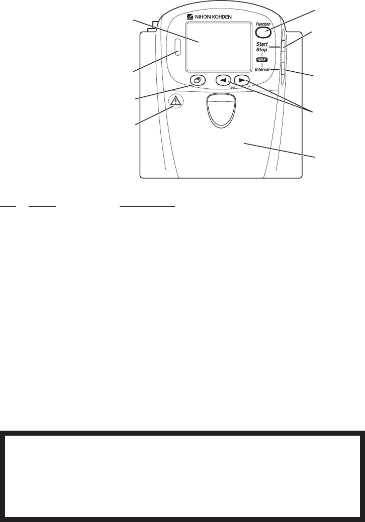
4 Function key Depending on the setting on the transmitter, this key suspends
alarms, pauses monitoring on the receiving monitor or transmits
“Patient confirmed” message.
On a SETUP screen, this key registers the selected setting and
moves the cursor to the next setting item.
On a CHECK screen, this key starts or stops maintenance test.
5 NIBP Start/Stop key Starts/stops NIBP measurement in selected mode.
6 NIBP Interval key Selects NIBP measurement mode.
7 Lead/Scroll keys On the numeric and waveform screen, these keys change the ECG
lead.
On the waveform review screen, these keys scroll data.
On a SETUP screen, these keys move the cursor.
8 Battery case Contains three 1.5 V dry cell batteries (AA TYPE).
WARNING
Close the battery case cover during operation. If the transmitter is used with the
battery case cover open, anyone who touches the opened battery case may receive
an electrical shock when defibrillation is performed. Touching the opened battery case
may cause electrostatic discharge and intermittently interfere with the waveform or
data.
Operator’s Manual ZM-540PA/541PA 5
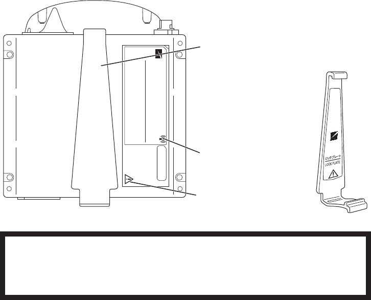
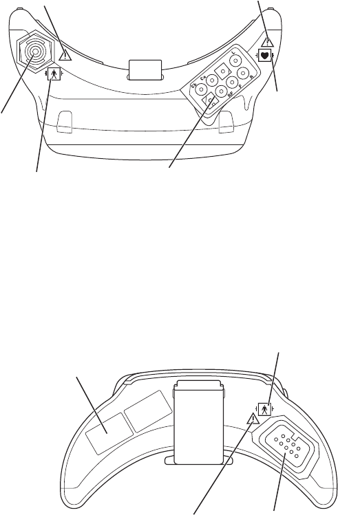
Rear Panel
Refer to the symbol
page.
Refer to the WARNING
below.
Lock plate
Fastens the transmitter to an NIBP cuff.
WARNING
This transmitter is not waterproof. If detergent or liquid spills into the transmitter, stop
using it and contact your Nihon Kohden representative. If a wet transmitter is used,
the patient or operator may receive an electrical shock or injury.
6 Operator’s Manual ZM-540PA/541PA
Top Panel
NIBP socket:
Connects the cuff
hose.
Refer to the WARNING on the
next page.
Refer to the symbol page.
Refer to the WARNING on the
next page.
Refer to the symbol
page.
ECG/impedance RESP socket:
Connects the electrode lead for measuring
ECG and/or respiration (impedance).
Bottom Panel
Refer to the WARNING
on the next page.
Refer to the symbol page.
SpO2 socket:
Connects the SpO2
probe.
Channel number label:
Indicates the channel number of the
transmitter. Attach the channel number label
to the panel of the receiving monitor.

Operator’s Manual ZM-540PA/541PA 7
WARNING
Before defibrillation, all persons must
keep clear of the bed and must not
touch the patient or any equipment or
cord connected to the patient. Failure
to follow this warning may cause
electrical shock or injury.
WARNING
When performing defibrillation,
discharge as far as possible from
electrodes, patches and any gel,
cream or medicine on the chest of the
patient. If there is a possibility that the
defibrillator paddle could touch these
materials, remove them from the
patient. If the defibrillator paddle
directly contacts these materials, the
discharged energy may cause skin
burn to the patient.
WARNING
When the transmitter is used with an
electrosurgical unit (ESU), firmly
attach the entire area of the ESU
return plate. Otherwise, the current
from the ESU flows into the electrodes
of the transmitter, causing electrical
burn where the electrodes are
attached. For details, refer to the ESU
manual.
CAUTION
Do not shake or swing the transmitter
while holding the leads or cables
connected to the transmitter. The
transmitter may come off and injure
someone or damage surrounding
instruments.

8 Operator’s Manual ZM-540PA/541PA
Important Safety Information
General
WARNING
Never use the transmitter in the
presence of any flammable anesthetic
gas or high concentration oxygen
atmosphere. Failure to follow this
warning may cause explosion or fire.
WARNING
Never use the transmitter in a
hyperbaric oxygen chamber. Failure to
follow this warning may cause
explosion or fire.
WARNING
Do not take this transmitter into the
MRI test room. This transmitter is not
designed to be used during MRI tests.
WARNING
When performing MRI test, remove all
electrodes, probe and cuff from the
patient which are used with this
transmitter. Failure to follow this
warning may cause skin burn on the
patient. For details, refer to the MRI
manual.
WARNING
Before defibrillation, all persons must
keep clear of the bed and must not
touch the patient or any equipment or
cord connected to the patient. Failure
to follow this warning may cause
electrical shock or injury.
WARNING
When performing defibrillation,
discharge as far as possible from
electrodes, patches and any gel,
cream or medicine on the chest of the
patient. If there is a possibility that the
defibrillator paddle could touch these
materials, remove them from the
patient. If the defibrillator paddle
directly contacts these materials, the
discharged energy may cause skin
burn to the patient.

Operator’s Manual ZM-540PA/541PA 9
WARNING
When the transmitter is used with an
electrosurgical unit (ESU), firmly
attach the entire area of the ESU
return plate. Otherwise, the current
from the ESU flows into the electrodes
of the transmitter, causing electrical
burn where the electrodes are
attached. For details, refer to the ESU
manual.
WARNING
This transmitter is not waterproof. If
detergent or liquid spills into the
transmitter, stop using it and contact
your Nihon Kohden representative. If a
wet transmitter is used, the patient or
operator may receive an electrical
shock or injury.
WARNING
Close the battery case cover during
operation. If the transmitter is used
with the battery case cover open,
anyone who touches the opened
battery case may receive an electrical
shock when defibrillation is performed.
Touching the opened battery case
may cause electrostatic discharge and
intermittently interfere with the
waveform or data.
WARNING
Do not use the same transmitter on
more than one patient at the same
time. Do not connect different sensors
on different patients to the same
transmitter.
CAUTION
Only use Nihon Kohden specified
electrodes, electrode leads, SpO2
probes, and NIBP cuffs. Otherwise,
the maximum performance from the
transmitter cannot be guaranteed.
CAUTION
Do not reuse disposable parts and
accessories.
CAUTION
The measurement values and
displayed waveforms on the
transmitter and receiving monitor may
be different due to timing delay of the
display or difference in detection
settings.
CAUTION
Do not shake or swing the transmitter
while holding the leads or cables
connected to the transmitter. The
transmitter may come off and injure
someone or damage surrounding
instruments.

10 Operator’s Manual ZM-540PA/541PA
CAUTION
Be aware that signal loss and artifact
may occur because of the multipath
cancellation* when using a transmitter.
* Multipath Cancellation (Standing Wave
Interference)
When a radio wave reflects off a surface,
there may be some points in the room where
the reflected and direct waves are exactly
out of phase. At these points in the room, the
reflected and direct waves cancel each other
out so that the signal strength is 0. This is
called “multipath cancellation” or “standing
wave interference”. Locations where signal
loss occurs are called “null spots”. If the
transmitter is moving or nearby people or
objects are moving, null spots can occur
anytime and anywhere.
CAUTION
Turn off the power of mobile phones,
small wireless devices and other
devices which produce strong
electromagnetic interference around a
patient (except for devices allowed by
the hospital administrator). Radio
waves from devices such as mobile
phones or small wireless devices may
be mistaken as pulse waves and the
displayed data may be incorrect.
CAUTION
• Do not use the same channel
for different patients. If the same
channel is used for two patients, the
two patients’ data will be lost due to
mutual modulation interference, or
another patient’s data may appear
on the receiving monitor screen.
• Do not use two transmitters with
adjacent channels in the same
hospital. If transmitters with
adjacent channels are used, their
radio waves interfere with each
other.
Output Signal
WARNING
Do not use the output signal from the receiving monitor as the synchronization signal
for other equipment such as IABP, MRI, echocardiography or defibrillator. There may
be time delay between the monitor and the other equipment caused by waveform
transmission delay and spike noise may interfere on the output signal and be
mistaken as a trigger.

Operator’s Manual ZM-540PA/541PA 11
Battery
CAUTION
Battery replacement must be
performed by the operator. When
replacing the batteries of a transmitter
that is currently used for a patient,
disconnect the electrode leads from
the transmitter before replacing
batteries or do not touch the patient
during replacement.
CAUTION
Refer to the battery and battery
charger manuals for details on
handling the batteries.
Transmitter Channel Management
WARNING
The following actions must be taken to properly receive the transmitter signal of the
correct patient on the receiving instrument. Otherwise, there may be signal loss or
signals may mix causing a serious accident, such as monitoring a different patient.
• Assign a channel administrator in the hospital and only he or she should manage
channel assignment.
• The channel administrator must manage the channels in the facility so that there is
no signal interference.
• When the transmitter channel is changed, the channel administrator must check
that the channel on the receiving monitor is also changed and the signal is properly
received.
• The channel administrator must replace the channel number label on the
transmitter with the new one after changing the channel.

12 Operator’s Manual ZM-540PA/541PA
For Patients Using Implantable Pacemaker
WARNING
Interaction Between Minute Ventilation Rate-Adaptive Pacemakers and Cardiac
Monitoring and Diagnostic Equipment*
The bioelectric impedance measurement sensor of a minute ventilation rate-adaptive
implantable pacemaker may be affected by transmitter which is connected to the
same patient. If this occurs, the pacemaker may pace at its maximum rate and the
transmitter may give incorrect data to the monitor. If this occurs, disconnect the
electrode leads from the patient or change the setting on the pacemaker by referring
to the pacemaker’s manual. For more details, contact your pacemaker representative
or Nihon Kohden representative.
* Minute ventilation is sensed in rate-adaptive pacemakers by a technology known as bioelectric
impedance measurement (BIM). Many medical devices in addition to pacemakers use this
technology. When one of these devices is used on a patient with an active, minute ventilation rate-
adaptive pacemaker, the pacemaker may erroneously interpret the mixture of BIM signals created
in the patient, resulting in an elevated pacing rate.
For more information, see the FDA web site.
http://www.fda.gov/cdrh/safety.html
ECG Monitoring
CAUTION
Only use Nihon Kohden specified
electrodes and electrode leads. When
other electrodes or electrode leads
are used, the “CHECK
ELECTRODES” message may appear
and monitoring may stop.
CAUTION
When the “ELECTRODE OFF” or
“CHECK ELECTRODES” message is
displayed on the receiving monitor,
ECG is not monitored properly and
the ECG alarm does not function.
Check the electrode, electrode leads,
and if necessary, replace with new
ones.

Operator’s Manual ZM-540PA/541PA 13
SpO2 Monitoring
WARNING
SpO2 measurement may be incorrect
in the following cases.
• When the patient’s
carboxyhemoglobin or
methemoglobin increases
abnormally.
• When dye is injected in the blood.
• When using an electrosurgical unit.
• During CPR.
• When measuring at a site with
venous pulse.
• When there is body movement.
• When the pulse wave is small
(insufficient peripheral circulation).
WARNING
When not monitoring SpO2,
disconnect the SpO2 cable from the
transmitter. Otherwise, noise from the
probe sensor may interfere and
incorrect data is displayed on the
screen.
WARNING
• When using the TL-201T finger
probe, do not fasten the probe and
cable to the finger by wrapping
with tape. This may cause burn,
congestion or pressure necrosis
from poor blood circulation.
• When using probes other than the
TL-201T finger probe, to avoid poor
circulation, do not wrap the tape too
tight. Check the blood circulation
condition by observing the skin
color and congestion at the skin
peripheral to the probe attachment
site. Even for short-term monitoring,
there may be burn or pressure
necrosis from poor blood circulation,
especially on neonates or low
birth weight infants whose skin is
delicate. Accurate measurement
cannot be performed on a site with
poor peripheral circulation.
WARNING
Check the circulation condition by
observing the skin color at the
measurement site and pulse
waveform. Change the measurement
site every 8 hours for disposable
probes and every 4 hours for reusable
probes (every 8 hours for TL-630T/TL-
631T series probe). The skin
temperature may increase at the
attached site by 2 or 3°C (4 or 5°F)
and cause a burn or pressure
necrosis. When using the probe on the
following patients, take extreme care
and change the measurement site
more frequently according to
symptoms and degree.
• Patient with a fever
• Patient with peripheral circulation
insufficiency
• Neonate or low birth weight infant
with delicate skin

14 Operator’s Manual ZM-540PA/541PA
WARNING
When monitoring SpO2 of a patient
who is receiving photodynamic
therapy, the light from the finger probe
sensor may cause a burn.
Photodynamic therapy uses a
photosensitizing agent that has a side
effect of photosensitivity.
CAUTION
Refer to the probe instruction manual
for details.
CAUTION
The disposable probe is not sterilized.
Use the disposable probe only for a
single patient. Never reuse the
disposable probe for another patient
because it causes cross infection.
CAUTION
NIBP and SpO2 can be measured on
the same limb, but the SpO2
monitoring might not be accurate
during NIBP measurement. Be careful
when reading the SpO2 values.*
* Monitoring SpO2 during NIBP Measurement
When the SpO2 probe is attached to the
same limb as the NIBP cuff, the blood
flow decreases during NIBP measurement
and pulse wave cannot be detected and
SpO2 cannot be monitored properly. When
“INHIBIT SpO2 DURING NIBP” on the
PARAMETER SETUP screen is set to ON
(factory default setting), SpO2 monitoring is
paused during NIBP measurement to avoid
SpO2 alarm occurrence. However, when
monitoring SpO2 on the same limb as the
NIBP, be careful when reading SpO2 values.
CAUTION
While a patient is on medication which
causes vasodilation, the pulse
waveform may change and in rare
cases the SpO2 value might not be
displayed.
CAUTION
Normal external light does not affect
monitoring but strong light such as a
surgical light or sunlight may affect
monitoring. If affected, cover the
measuring site with a blanket.
CAUTION
When a message indicates a faulty
probe, stop monitoring and replace
the probe with a new one.

Operator’s Manual ZM-540PA/541PA 15
CAUTION
Do not use a damaged or
disassembled probe. It causes
incorrect measurement and may
injure the patient.
CAUTION
Do not use a probe which is
deteriorated by aging. Accurate
measurement cannot be performed.
CAUTION
If the attachment site is dirty with
blood or bodily fluids, clean the
attachment site before attaching the
probe. If there is nail polish on the
attachment site, remove the polish.
Otherwise, the amount of transmitted
light decreases, and measured value
may be incorrect or measurement
cannot be performed.
CAUTION
If the skin gets irritated or redness
appears on the skin from the probe,
change the attachment site or stop
using the probe. Take extreme care for
the patients with delicate skin.
CAUTION
Do not pull or bend the probe cable,
and do not put caster feet on the
probe cable. Do not immerse the
disposable probe cable in chemical
solutions or water. Failure to follow
these instructions may cause cable
discontinuity, short circuit, skin burn
on the patient and incorrect
measurement data. Replace any
broken probe with a new one.
CAUTION
When the probe is attached on an
appropriate site with sufficient
circulation and the error message
confirming the probe attachment
repeatedly appears, the probe may be
deteriorated. Replace it with a new
one.

16 Operator’s Manual ZM-540PA/541PA
NIBP Monitoring
WARNING
Be careful when measuring NIBP on a
patient with known bleeding disorders
or coagulation. After NIBP
measurement, there may be dot
hemorrhage, or circulatory disorder by
thrombus where the cuff is attached.
WARNING
NIBP measurement may be incorrect
in the following cases.
• When using an electrosurgical unit
• When there is body movement
• When the pulse wave is small
(insufficient peripheral circulation)
• Too many arrhythmias
• When there is vibration
• When there is a rapid blood
pressure change
• During CPR
WARNING
When performing NIBP
measurements in STAT mode or 5
minute intervals, periodically remove
the cuff from the patient for ventilation.
The skin temperature may increase at
the cuff attachment site by 2 or 3°C (4
or 5°F). When measuring a patient
with a fever or peripheral circulation
insufficiency, it may cause a burn.
CAUTION
Do not wrap the cuff on an arm or
thigh which is used for injection. NIBP
measurement on an arm or thigh
which is used for injection may cause
reflux of blood and stop injection.
CAUTION
Do not wrap the cuff too tight. It may
cause poor blood circulation and
congestion. If the cuff is wrapped too
loosely, the NIBP value may increase.
CAUTION
Do not attach the cuff to the site
where there is injury or inflammation.
If the skin gets irritated or redness
appears on the skin from the cuff,
change the attachment site or stop
using the cuff. Take extreme care on
the patients with delicate skin.
CAUTION
When using an extension hose, check
that the extension hose is not bent or
squeezed. Otherwise, the cuff might
not inflate or deflate. If the cuff cannot
deflate, it may cause congestion on
the patient at the cuff attachment site.

Operator’s Manual ZM-540PA/541PA 17
CAUTION
When performing NIBP measurement
repeatedly, have a rest between
measurements to recover adequate
circulation.
Maintenance
CAUTION
This transmitter is not waterproof. If
detergent or liquid spills into the
transmitter, stop cleaning or
disinfecting it and contact your Nihon
Kohden representative. The
transmitter needs to be checked for
safety and function before use.
CAUTION
Never disassemble or repair the
transmitter. Disassembly and repair
must be performed by qualified
service personnel.

18 Operator’s Manual ZM-540PA/541PA
Preparation on Transmitter
Batteries
WARNING and CAUTION for Handling Batteries
CAUTION
Refer to the battery and battery
charger manuals for details on
handling the batteries.
CAUTION
When the transmitter is not in use,
remove the batteries. When the
batteries are installed, battery power
is consumed even when
measurement is not performed. When
NiMH batteries are left in the
transmitter when it is not used, the
batteries may overdischarge and leak
liquid which makes the batteries
unusable and damages the
transmitter.
CAUTION
Do not handle the batteries with wet
hands.
NOTE
Remove the batteries from the transmitter before disposing of it.
Battery Lifetime
Use three AA type alkaline dry cell batteries. NiMH batteries can also be used but the lifetime of
alkaline batteries is longer. The lifetime of NiMH batteries is about 1/2 of alkaline batteries (when
fully charged).
With new Nihon Kohden recommended alkaline batteries, the transmitter can continuously measure
ECG, respiration, SpO2 and NIBP for approximately 1 day. The measurement is performed at room
temperature, NIBP is measured in auto mode at 60 minute intervals and SpO2 is measured on an
index finger of a male patient with weight 60 kg. Operation time depends on the thickness of the
SpO2 probe attachment site.
Recommended batteries
NiMH secondary: SANYO HR-3UF (W)
Battery charger: SANYO NC-M55
Alkaline primary: Nihon Kohden Medipower (equivalent to Panasonic LR6 (G))
Operator’s Manual ZM-540PA/541PA 19
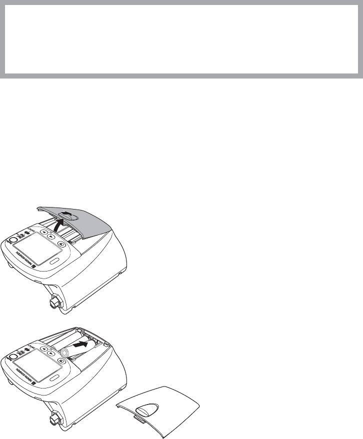
Installing (Replacing) Batteries
CAUTION
Battery replacement must be performed by the operator. When replacing the batteries
of a transmitter that is currently used for a patient, disconnect the electrode leads
from the transmitter before replacing batteries or do not touch the patient during
replacement.
If electrode leads are attached to the patient and the person replacing batteries touches the patient
during battery replacement, excess patient leakage current may flow into the patient.
NOTE
• Replace all batteries at the same time.
• Do not use different types of batteries together.
• Insert the batteries with the correct polarity (+ and –).
• The capacity of rechargeable NiMH batteries is reduced if the batteries are recharged
before they are fully discharged. For details, refer to the battery operator’s manual.
1. Remove the battery case cover.
2. Insert three new or fully charged batteries into
the battery case observing the correct polarity.
20 Operator’s Manual ZM-540PA/541PA
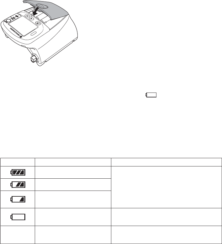
3. Close the cover.
The transmitter is automatically turned on when the
batteries are installed and the cover is closed.
Situations Requiring Battery Replacement
Replace the batteries when any of the following occurs:
• The transmitter displays the “BATTERY WEAK” message or “ ” icon.
• The transmitter generates a constant alarm (continuous “peep” sound).
• The transmitter LCD does not display anything when the power is turned on.
• The receiving monitor displays a battery replacement message.
Battery Level Indication
The following icons on the LCD indicate the battery level. When “PROTOCOL” on the SYSTEM
SETUP screen is set to 57, the battery level indication is transmitted to the receiving monitor.
Indication Battery Level Message on the Receiving Monitor
Fully charged batteries
There is no message on the monitor.
Batteries are 2/3 full.
Batteries are low. NIBP cannot
be measured. Replace batteries.
Batteries are very weak. Message requiring battery replacement is
displayed.
No indication Dead batteries No signal can be transmitted to the monitor.
There is no indication on the monitor.
Turning On the Transmitter
When the batteries are installed correctly, the power is turned on. A one second “peep” sounds and
the startup screen appears, then the check electrodes screen appears. (There is no “peep” sound
when there is no battery power.)
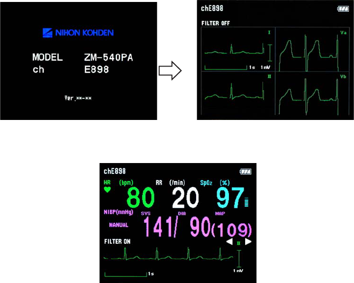
Operator’s Manual ZM-540PA/541PA 21
After checking that the ECG is stable on the check electrodes screen, press the Screen key to display
the numeric and waveform screen.
For details on the screen, refer to the “Screen Descriptions” section.
Check Items Before Use
Before turning on the transmitter power, check the following to confirm that the transmitter can be
used in normal and safe condition.
Appearance
• There are no damaged or dirty parts on the outside of the transmitter (LCD, keys, sockets, battery
case cover, battery case, lock plate, etc.).
• The transmitter is completely dry.
• The electrodes, electrode lead, SpO2 probe and NIBP cuff are not broken.
Batteries
• The battery polarity is correct.
• The battery case spring is firmly attached and the battery is not loose.
• The battery case cover is firmly closed.
Channel Setting
• The transmitter channel matches the receiving monitor channel.
• There is no nearby transmitter with the same channel.
22 Operator’s Manual ZM-540PA/541PA
Check Items After Power On
After turning on the power, check the following.
Power On
• The transmitter generates a one second “peep” sound and the startup screen appears.
• The transmitter displays the check electrodes screen.
• The transmitter is not too hot.
• The transmitter does not display the “BATTERY WEAK” message.
• The transmitter does not interfere with the operation of other medical instruments.
Daily Check
• The “signal loss” message is not displayed on the receiving monitor when the transmitter is inside
the receiving range of the monitor.
• The battery replacement message is not displayed on the monitor.
• The keys on the transmitter function properly.
• The LCD brightness is appropriate. To adjust brightness, refer to the “Changing SYSTEM SETUP
Settings” section.
Check Items After Use
To use the transmitter in safe and optimum condition for next time, check the following.
Before Turning Power Off
• Temporarily changed settings are changed back to the previous settings.
• There was no malfunction on the transmitter.
Storage
• ECG electrode leads, SpO2 probe and NIBP cuff are cleaned and disinfected.
• If the transmitter got wet, liquid is wiped off and the transmitter is thoroughly dried.
• There are enough consumables, such as disposable electrodes.
• The transmitter power is turned off by removing batteries from the transmitter.
• Dead batteries are disposed of properly.
Turning Off the Transmitter
To turn off the power, remove batteries. When the power is turned off, the saved waveform and
numeric data are deleted.
Operator’s Manual ZM-540PA/541PA 23
Changing the Transmitter Channel
The channel of the transmitter can be changed with an optional QI-901PK Channel Writer.
WARNING
The following actions must be taken to properly receive the transmitter signal of the
correct patient on the receiving instrument. Otherwise, there may be signal loss or
signals may mix causing a serious accident, such as monitoring a different patient.
• Assign a channel administrator in the hospital and only he or she should manage
channel assignment.
• The channel administrator must manage the channels in the facility so that there is
no signal interference.
• When the transmitter channel is changed, the channel administrator must check
that the channel on the receiving monitor is also changed and the signal is properly
received.
• The channel administrator must replace the channel number label on the
transmitter with the new one after changing the channel.
NOTE
• The software version of the QI-901PK channel writer must be 02-01 or later to change
the channel on the transmitter.
• The channel writer must be used outside the patient environment.
The channel is displayed in the upper left corner of the screen.
Channel

24 Operator’s Manual ZM-540PA/541PA
Changing Parameter and System Setup Settings
The initial settings on the PARAMETER SETUP and SYSTEM SETUP screens can only be
changed before monitoring. Changing these settings during monitoring interrupts monitoring.
NOTE
Changing Parameter and System Setup settings must be done by qualified personnel.
Notes on Parameter Settings
When monitoring NIBP and SpO2, the following setting must be set as indicated in the table
to properly transmit the monitoring data to the receiving monitor. Otherwise, SpO2 cannot be
monitored properly during NIBP measurement.
Some receiving monitors require the software to be upgraded. For details, contact your Nihon
Kohden representative.
SpO2 probe attachment site INHIBIT SpO2 DURING NIBP setting
Probe attached to the same limb as the cuff* ON
Probe attached to the limb without cuff OFF
* When the SpO2 probe is attached to the same limb as the NIBP cuff and the cuff is inflated,
the SpO2 value becomes unstable and SpO2 or PR alarm may occur.

Operator’s Manual ZM-540PA/541PA 25
Changing PARAMETER SETUP Settings
Parameter Setup Setting List
The factory default settings are underlined.
Setting Item Description Settings
ECG ELECTRODES Select the electrode lead type. IEC, AHA
LEAD TYPE Select the type of ECG leads. AUTO, 6 LEADS
ECG
MEASUREMENT
Turn ECG monitoring on or off. When electrodes are
attached to the patient and ECG leads are connected,
ECG monitoring starts even when this setting is set to
OFF.
If this setting is set to OFF, the same setting on the
receiving monitor must also be set to OFF.
NOTE
When “PROTOCOL” on the transmitter is set to
57 and the receiving monitor is able to receive
protocol 57, ECG measurement on the receiving
monitor is automatically set to OFF when this
setting is set to OFF on the transmitter.
ON, OFF
RESP
MEASUREMENT
Turn respiration monitoring on or off.
When this setting is set to OFF, the same setting on the
receiving monitor is automatically set to OFF.
ON, OFF
SpO2 RESPONSE
Select the SpO2 response mode.
FAST: Select this for special applications that
require a fast response. FAST is suitable
for detecting short apnea.
NORMAL: For normal monitoring.
SLOW: Select this when you need to suppress a
rapid change in SpO2.
FAST, NORMAL,
SLOW
INHIBIT SpO2
DURING NIBP
Turn SpO2 monitoring on or off during NIBP
measurement. ON, OFF
SELECTABLE
INTERVALS (min)
Select the NIBP measurement modes for the mode
selection.
STAT, 5, 10, 15,
30, 60, 120, 240
INITIAL INTERVAL
(min)
Select the initial NIBP measurement mode at power
on.
MANUAL, 5, 10,
15, 30, 60, 120,
240
NIBP MODE AFTER
STAT (min)
Select the NIBP measurement mode after completing
STAT measurement.
MANUAL, 5, 10,
15, 30, 60, 120,
240
START/FINISH
SOUND
Turn ON or OFF the sound for NIBP measurement
start/finish.
START: ON, OFF
FINISH: ON, OFF
26 Operator’s Manual ZM-540PA/541PA
Setting Item Description Settings
OLD NIBP DATA/
AFTER (min)
Select whether to hide or dim the NIBP data after
measurement and how long to wait after measurement
to dim or hide it.
DATA: HIDE,
DIM
AFTER: 5, 10, 30
INITIAL CUFF
PRESSURE (mmHg) Select the NIBP cuff inflation pressure. 120, 150, 180,
210, 240
Displaying the PARAMETER SETUP Screen
1. Turn off the transmitter by removing one
battery.
2. While pressing the Function key, turn on
the transmitter (install the battery). The
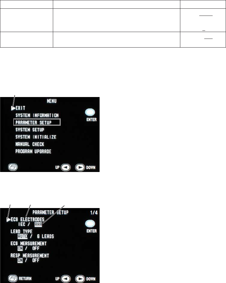
MENU screen appears.
3. Press the
▼
key to move the cursor to
“PARAMETER SETUP”.
4. Press the Function key to enter
PARAMETER SETUP. The current
settings are highlighted.
5. Change settings:
• To move the cursor and select the setting
item, press the
▼
or
▼
key then press
the Function key.
• To select and register the setting, press
the
▼
or
▼
key then press the Function
key.
• To cancel changing the setting of the
selected item, press the Screen key.
6. When changing settings on the
PARAMETER SETUP screen is complete,
press the Screen key to return to the
MENU screen.
Cursor
MENU screen
Setting item
PARAMETER SETUP screen - page 1
Setting
Cursor
7. Press the
▼
or
▼
key to move the cursor to “EXIT”.
8. Press the Function key. The numeric and waveform screen appears.
Operator’s Manual ZM-540PA/541PA 27
1. On the PARAMETER SETUP screen,
press the
▼
key to move the cursor to
“ECG ELECTRODES”.
2. Press the Function key. The cursor moves
to the selection item.
3. Press the
▼
key to select “IEC” or “AHA”.
4. Press the Function key to register the
selected setting. The cursor returns to
“ECG ELECTRODES”.
Changing Parameter Setup Settings
ECG ELECTRODES
Select the electrode lead type.
Selected setting
Cursor
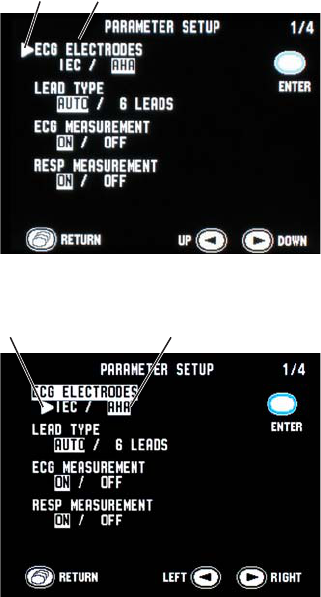
LEAD TYPE
Select the type of ECG leads. In normal use, select “AUTO”. When using DIN type lead with 6
electrodes, select “6 LEADS”.
1. On the PARAMETER SETUP screen, press the
▼
key to move the cursor to “LEAD TYPE”.
2. Press the Function key.
3. Press the
▼
key to select “AUTO” or “6 LEADS”.
4. Press the Function key to register the selected setting. The cursor returns to “LEAD TYPE”.
Setting item
Cursor
28 Operator’s Manual ZM-540PA/541PA
ECG MEASUREMENT
Turn ECG monitoring on or off. When electrodes are attached to the patient and ECG leads are
connected, ECG monitoring starts even when this setting is set to OFF.
If this setting is set to OFF, the same setting on the receiving monitor must also be set to OFF.
NOTE
When “PROTOCOL” on the transmitter is set to 57 and the receiving monitor is able to
receive protocol 57, ECG measurement on the receiving monitor is automatically set to
OFF when this setting is set to OFF on the transmitter.
1. On the PARAMETER SETUP screen, press the
▼
key to move the cursor to “ECG
MEASUREMENT”.
2. Press the Function key.
3. Press the
▼
key to select “ON” or “OFF”.
4. Press the Function key to register the selected setting. The cursor returns to “ECG
MEASUREMENT”.
RESP MEASUREMENT
Turn respiration monitoring on or off. When this setting is set to OFF, the same setting on the
receiving monitor is automatically set to OFF.
1. On the PARAMETER SETUP screen, press the
▼
key to move the cursor to “RESP
MEASUREMENT”.
2. Press the Function key.
3. Press the
▼
key to select “ON” or “OFF”.
4. Press the Function key to register the selected setting. The cursor returns to “RESP
MEASUREMENT”.
Operator’s Manual ZM-540PA/541PA 29
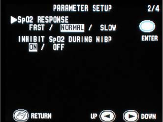
SpO2 RESPONSE
Select the SpO2 response mode.
FAST: Select this for special applications that require a fast response. FAST is suitable for
detecting short apnea.
NORMAL: For normal monitoring.
SLOW: Select this when you need to suppress a rapid change in SpO2.
1. On the PARAMETER SETUP screen,
press the
▼
key to move the cursor to
“SpO2 RESPONSE”. “SpO2 RESPONSE”
is on the second page of the PARAMETER
SETUP screen.
2. Press the Function key.
3. Press the
▼
key to select “FAST”,
“NORMAL” or “SLOW”.
4. Press the Function key to register the
selected setting. The cursor returns to
“SpO2 RESPONSE”.
PARAMETER SETUP screen - page 2
INHIBIT SpO2 DURING NIBP
Turn SpO2 monitoring on or off during NIBP measurement.
When the SpO2 probe is attached to the same limb as the NIBP cuff and this setting is set to OFF, the
pulse may become unstable and SpO2 or PR alarm may occur. It is recommended to set this setting
to ON so that SpO2 is not measured during NIBP measurement.
When the SpO2 probe is attached to the other limb from the NIBP cuff, this setting can be set to
OFF.
NOTE
When this “INHIBIT SpO2 DURING NIBP” is set to OFF, refer to the “Monitoring SpO2
during NIBP Measurement” section.
1. On the PARAMETER SETUP screen, press the
▼
key to move the cursor to “INHIBIT
SpO2 DURING NIBP”. “INHIBIT SpO2 DURING NIBP” is on the second page of the
PARAMETER SETUP screen.
2. Press the Function key.
3. Press the
▼
key to select “ON” or “OFF”.
30 Operator’s Manual ZM-540PA/541PA
4. Press the Function key to register the selected setting. The cursor returns to “INHIBIT SpO2
DURING NIBP”.
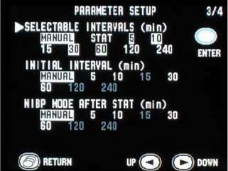
SELECTABLE INTERVALS (min)
When the NIBP INTERVAL key is pressed, the measurement mode changes according to the modes
selected in this item. MANUAL mode is already selected for the mode selection.
PARAMETER SETUP screen - page 3
1. On the PARAMETER SETUP screen,
press the
▼
key to move the cursor
to “SELECTABLE INTERVALS”.
“SELECTABLE INTERVALS” is on the
third page of the PARAMETER SETUP
screen.
2. Press the Function key.
3. Press the
▼
key to select or unselect the
mode. The selected modes are highlighted.
4. Press the Function key to register the
selected setting. The cursor returns to
“SELECTABLE INTERVALS”.
INITIAL INTERVAL (min)
Select the initial NIBP measurement mode at power on.
1. On the PARAMETER SETUP screen, press the
▼
key to move the cursor to “INITIAL
INTERVAL”. “INITIAL INTERVAL” is on the third page of the PARAMETER SETUP screen.
2. Press the Function key.
3. Press the
▼
key to select the mode. Only the mode or interval selected for “SELECTABLE
INTERVALS” are available.
4. Press the Function key to register the selected setting. The cursor returns to “INITIAL
INTERVAL”.
NIBP MODE AFTER STAT (min)
Select the NIBP measurement mode after completing the STAT measurement.
1. On the PARAMETER SETUP screen, press the
▼
key to move the cursor to “NIBP MODE
AFTER STAT”. “NIBP MODE AFTER STAT” is on the third page of the PARAMETER
SETUP screen.
Operator’s Manual ZM-540PA/541PA 31
2. Press the Function key.
3. Press the
▼
key to select the mode. Only the mode or interval selected for “SELECTABLE
INTERVALS” are available.
4. Press the Function key to register the selected setting. The cursor returns to “NIBP MODE
AFTER STAT”.
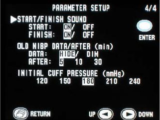
START/FINISH SOUND
Turn on or off the sound for NIBP measurement start and finish.
PARAMETER SETUP screen - page 4
1. On the PARAMETER SETUP screen,
press the
▼
key to move the cursor to
“START/FINISH SOUND”. “START/
FINISH SOUND” is on the fourth page of
the PARAMETER SETUP screen.
2. Press the Function key. The cursor moves
to “START”.
3. Press the
▼
key to turn “ON” or “OFF” the
sound for NIBP measurement start.
4. Press the Function key to register the
setting for “START”. The cursor moves to
“FINISH”.
5. Press the
▼
key to turn “ON” or “OFF” the
sound for NIBP measurement finish.
6. Press the Function key to register the
selected setting. The cursor returns to
“START/FINISH SOUND”.
OLD NIBP DATA/AFTER (min)
Select whether to dim or hide the NIBP data after measurement and how long to wait after NIBP
measurement to dim or hide it.
1. On the PARAMETER SETUP screen, press the
▼
key to move the cursor to “OLD NIBP
DATA/AFTER”. “OLD NIBP DATA/AFTER” is on the fourth page of the PARAMETER
SETUP screen.
2. Press the Function key. The cursor moves to “DATA”.

32 Operator’s Manual ZM-540PA/541PA
3. Press the
▼
key to select “HIDE” or “DIM” the NIBP data.
4. Press the Function key to register the setting for “DATA”. The cursor moves to “AFTER”.
5. Press the
▼
key to select the interval after NIBP measurement to dim or hide.
6. Press the Function key to register the selected setting. The cursor returns to “OLD NIBP DATA/
AFTER”.
INITIAL CUFF PRESSURE (mmHg)
Select the NIBP cuff inflation pressure.
1. On the PARAMETER SETUP screen, press the
▼
key to move the cursor to “INITIAL CUFF
PRESSURE”. “INITIAL CUFF PRESSURE” is on the fourth page of the PARAMETER
SETUP screen.
2. Press the Function key.
3. Press the
▼
key to select the inflation pressure.
4. Press the Function key to register the selected setting. The cursor returns to “INITIAL CUFF
PRESSURE”.
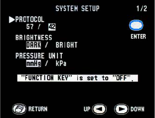
Changing SYSTEM SETUP Settings
System Setup Setting List
The factory default settings are underlined.
Setting Item Description Settings
PROTOCOL
Select the transmitting protocol.
57: New protocol. A central monitor with ORG-
9100A/9110A/9700A multiple patient receiver whose
software version 02-01 or later can receive this
protocol.
42: Old protocol. A central monitor with ORG-
9100A/9110A/9700A multiple patient receiver can
receive this protocol.
NOTE
When 57 is set, the receiving monitor must be able
to receive protocol 57. Otherwise, signals from the
transmitter cannot be received.
57, 42

Operator’s Manual ZM-540PA/541PA 33
Setting Item Description Settings
BRIGHTNESS Select the screen brightness. DARK,
BRIGHT
PRESSURE UNIT Select the unit for NIBP. mmHg, kPa
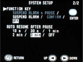
FUNCTION KEY
Select the function of the Function key.
SUSPEND ALARM & PAUSE:
Suspends alarm on the receiving monitor for 2
minutes. Pauses monitoring on the transmitter and
receiving monitor.
SUSPEND ALARM:
Suspends alarm on the receiving monitor for 2
minutes.
CONFIRM:
Displays the “PATIENT CONFIRMED” message
on the transmitter screen and transmits the
message to the receiving monitor.
OFF: No function.
NOTE
“SUSPEND ALARM & PAUSE” and “CONFIRM” can
only be set when PROTOCOL is set to 57.
SUSPEND
ALARM
& PAUSE,
SUSPEND
ALARM,
CONFIRM,
OFF
AUTO RESUME
AFTER PAUSE Select the interval to resume monitoring after PAUSE.
10 s, 30 s, 1
min, 2 min, 3
min, OFF
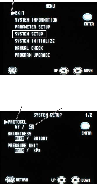
34 Operator’s Manual ZM-540PA/541PA
1. Turn off the transmitter by removing one
battery.
2. While pressing the Function key, turn on
the transmitter (install the battery). The
MENU screen appears.
3. Press the
▼
key to move the cursor to
“SYSTEM SETUP”.
4. Press the Function key to enter SYSTEM
SETUP. The current settings are
highlighted.
5. Change settings.
• To move the cursor and select the setting
item, press the
▼
or
▼
key then press
the Function key.
• To select and register the setting, press
the
▼
or
▼
key then press the Function
key.
• To cancel changing the setting of the
selected item, press the Screen key.
The SYSTEM SETUP screen has two
pages. To display the second page,
press the
▼
key when the cursor is at
“PRESSURE UNIT”.
6. When changing settings on the SYSTEM
SETUP screen is complete, press the
Screen key to return to the MENU screen.
7. Press the
▼
or
▼
key to move the cursor to
“EXIT”.
8. Press the Function key. The numeric and
waveform screen appears.
Cursor
MENU screen
Setting item
SYSTEM SETUP screen - page 1
Setting
Displaying the SYSTEM SETUP Screen
Operator’s Manual ZM-540PA/541PA 35
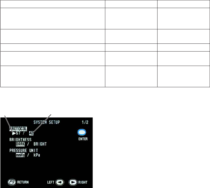
Changing System Setup Settings
PROTOCOL
Select the transmitting protocol. For differences between protocols, refer to the table below.
57: New protocol. A central monitor with ORG-9100A/9110A/9700A multiple patient receiver
whose software version 02-01 or later can receive this protocol.
42: Old protocol. A central monitor with ORG-9100A/9110A/9700A multiple patient receiver can
receive this protocol.
NOTE
When 57 is set, the receiving monitor must be able to receive protocol 57. Otherwise,
signals from the transmitter cannot be received.
Differences Between Protocols
Function Protocol 42 Protocol 57
Setting ECG MEASUREMENT to OFF on the
transmitter automatically turns off the ECG
measurement setting on the receiving monitor
No (ECG measurement
must be turned off on
the receiving monitor)
Yes
Pause monitoring on the receiving monitor from
the transmitter No Yes
Transmit “PATIENT CONFIRMED” message No Yes
Display battery level of the transmitter on the
receiving monitor No Yes
Transmit SpO2 messages
Some messages (refer
to the “Indication and
Message List” section)
All messages
Setting
Cursor 1. Press the
▼
key to move the cursor to
“PROTOCOL”.
2. Press the Function key.
3. Press the
▼
key to select “57” or “42”.
36 Operator’s Manual ZM-540PA/541PA
NOTE
FUNCTION KEY (on the second page
of the SYSTEM SETUP screen) can be
set to “SUSPEND ALARM & PAUSE” or
“CONFIRM” only when PROTOCOL is
“57”. If PROTOCOL is changed to “42”,
FUNCTION KEY is automatically changed
to “OFF”.
4. Press the Function key to register the
selected setting. The cursor returns to
“PROTOCOL”.
BRIGHTNESS
Select the screen brightness.
1. Press the
▼
key to move the cursor to “BRIGHTNESS”.
2. Press the Function key.
3. Press the
▼
key to select “DARK” or “BRIGHT”.
4. Press the Function key to register the selected setting. The cursor returns to “BRIGHTNESS”.
PRESSURE UNIT
Select the unit for NIBP.
1. Press the
▼
key to move the cursor to “PRESSURE UNIT”.
2. Press the Function key.
3. Press the
▼
key to select “mmHg” or “kPa”.
4. Press the Function key to register the selected setting. The cursor returns to “PRESSURE
UNIT”.
Operator’s Manual ZM-540PA/541PA 37
FUNCTION KEY
Select the function of the Function key.
SUSPEND ALARM & PAUSE: Suspends alarm on the receiving monitor for 2 minutes. Pauses
monitoring on the transmitter and receiving monitor.
SUSPEND ALARM: Suspends alarm on the receiving monitor for 2 minutes.
CONFIRM: Displays the “PATIENT CONFIRMED” message on the
transmitter screen and transmits the message to the receiving
monitor.
OFF: No function.
NOTE
“SUSPEND ALARM & PAUSE” and “CONFIRM” can only be set when PROTOCOL is set to
57.
SYSTEM SETUP screen - page 2
1. On the SYSTEM SETUP screen, press the
▼
key to move the cursor to “FUNCTION
KEY”. “FUNCTION KEY” is on the
second page of the SYSTEM SETUP
screen.
2. Press the Function key.
3. Press the
▼
key to select the function.
4. Press the Function key to register the
selected setting. The cursor returns
“FUNCTION KEY”.
AUTO RESUME AFTER PAUSE
Select the interval to resume monitoring after PAUSE.
1. Press the
▼
key to move the cursor to “AUTO RESUME AFTER PAUSE”. “AUTO RESUME
AFTER PAUSE” is on the second page of the SYSTEM SETUP screen.
2. Press the Function key.
3. Press the
▼
key to select interval.
4. Press the Function key to register the selected setting. The cursor returns to “AUTO RESUME
AFTER PAUSE”.
38 Operator’s Manual ZM-540PA/541PA
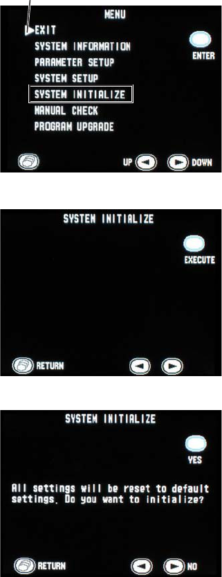
Cursor 1. Turn off the transmitter by removing a
battery.
2. While pressing the Function key, turn on
the transmitter (put back the battery). The
MENU screen appears.
3. Press the
▼
key to move the cursor to
“SYSTEM INITIALIZE”.
4. Press the Function key to enter SYSTEM
INITIALIZE screen.
5. Press the Function key to initialize settings.
The confirmation message appears.
To return to the MENU screen without
initializing, press the Screen key.
6. Press the Function key to initialize settings.
To cancel initializing, press the
▼
key. The
screen returns to the MENU screen.
Initializing Settings
Do the following procedure to initialize all settings, except for channel, to the factory default
settings.
Operator’s Manual ZM-540PA/541PA 39
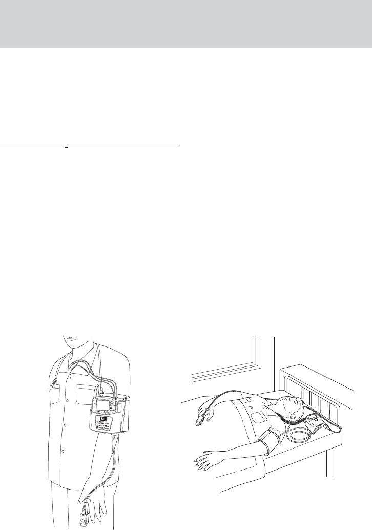
Attaching Electrodes, SpO2 Probe and NIBP Cuff
to the Patient
The transmitter can be attached to an arm of the patient or placed on the bedside. The required
length of the electrode leads and SpO2 probe cable depends on how the transmitter is to be attached
to the patient.
NOTE
Monitoring SpO2 during NIBP Measurement
When the SpO2 probe is attached to the same limb as the NIBP cuff, the blood flow
decreases during NIBP measurement and pulse wave cannot be detected and SpO2
cannot be monitored properly. When “INHIBIT SpO2 DURING NIBP” on the PARAMETER
SETUP screen is set to ON (factory default setting), SpO2 monitoring is paused during
NIBP measurement to avoid SpO2 alarm occurrence. However, when monitoring SpO2 on
the same limb as NIBP, be careful when reading SpO2 values.
When monitoring SpO2 is important, attach the probe to the limb to which the
NIBP cuff or catheter is not attached.
Attachment Examples
When transmitter is attached on an arm When transmitter is placed on a bedside
NOTE
When placing the transmitter on a bedside,
place it on a stable and flat place. If the
transmitter falls off, it may be damaged.
40 Operator’s Manual ZM-540PA/541PA
Attaching Electrodes
Selecting Electrode Lead
CAUTION
Only use Nihon Kohden specified electrodes and electrode leads. When other
electrodes or electrode leads are used, the “CHECK ELECTRODES” message may
appear and monitoring may stop.
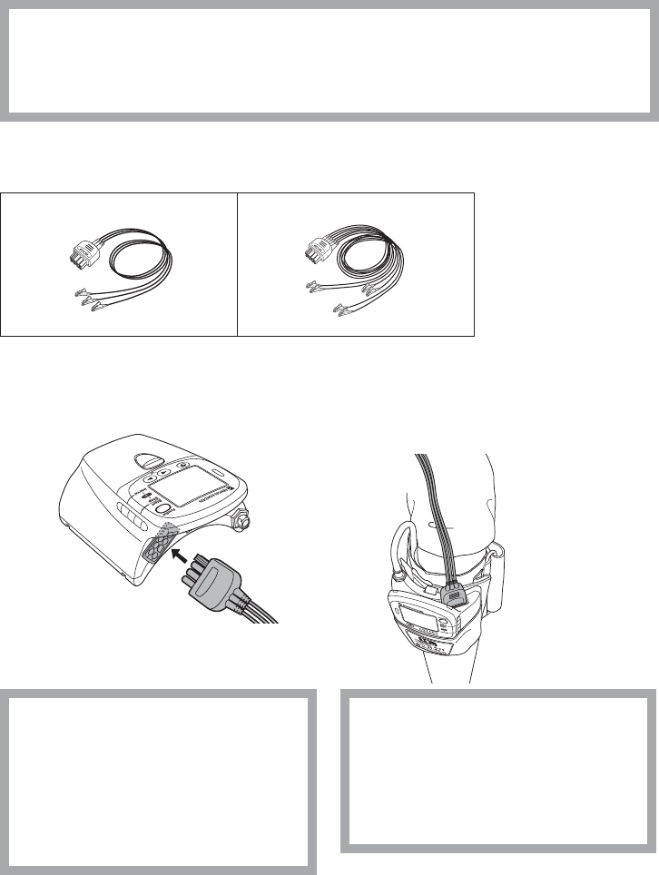
The following electrode leads can be used on the transmitter (option).
BR-903PA, 3 electrodes, clip type BR-906PA, 6 electrodes, clip type
Connecting the Electrode Lead to the Transmitter
Connect the electrode lead to the ECG/RESP socket on the transmitter.
When transmitter is attached on an arm
CAUTION
Do not shake or swing the transmitter
while holding the leads or cables
connected to the transmitter. The
transmitter may come off and injure
someone or damage surrounding
instruments.
CAUTION
Hold the connector of the electrode
lead when connecting/disconnecting
the electrode lead. If you disconnect
the electrode lead by pulling the lead,
it damages the electrode lead.
Operator’s Manual ZM-540PA/541PA 41
Electrode Position
Follow the physician’s instructions for electrode placement when available.
For ECG monitoring, electrodes are attached only on the chest to allow patient movement and
obtain continuous stable ECG. The following leads are examples. When also monitoring respiration,
refer to the “Electrode Position for Respiration Monitoring” section.
NOTE
The optimum electrode positions for ECG measurement are not always optimum for
respiration measurement. Select positions that are suitable for both ECG and respiration
measurement or positions which give priority to either ECG or respiration measurement.
Electrode Positions for ECG Monitoring
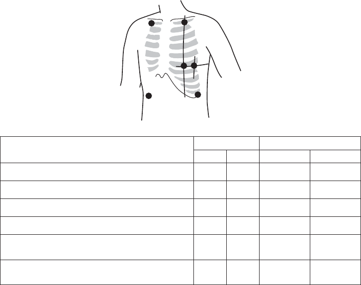
Six Electrodes
The 6-electrode method with lead II and lead V5 is effective for monitoring myocardial ischemia.
You can improve monitoring accuracy considerably by adding lead V4 to this combination. Va and
Vb can be at any position of the standard 12 leads V1 to V6, but V4 and V5 are most appropriate for
myocardial ischemic monitoring.
RA/R LA/L
RL/RF LL/F
Va/Ca
Vb/Cb
Electrode Position Symbol Lead Color
AHA IEC AHA IEC
Left infraclavicular fossa LA L Black Yellow
Right infraclavicular fossa RA R White Red
Below lowest rib on the left anterior axillary line LL F Red Green
Right anterior axillary line at the same level as LL/F RL RF Green Black
Fifth intercostal space on the left midclavicular line.
(V4 position of standard 12 leads) Va Ca Brown-blue White-
brown
Left anterior axillary line at the same level as Va.
(V5 position of standard 12 leads) Vb Cb Brown-
orange White-black
42 Operator’s Manual ZM-540PA/541PA
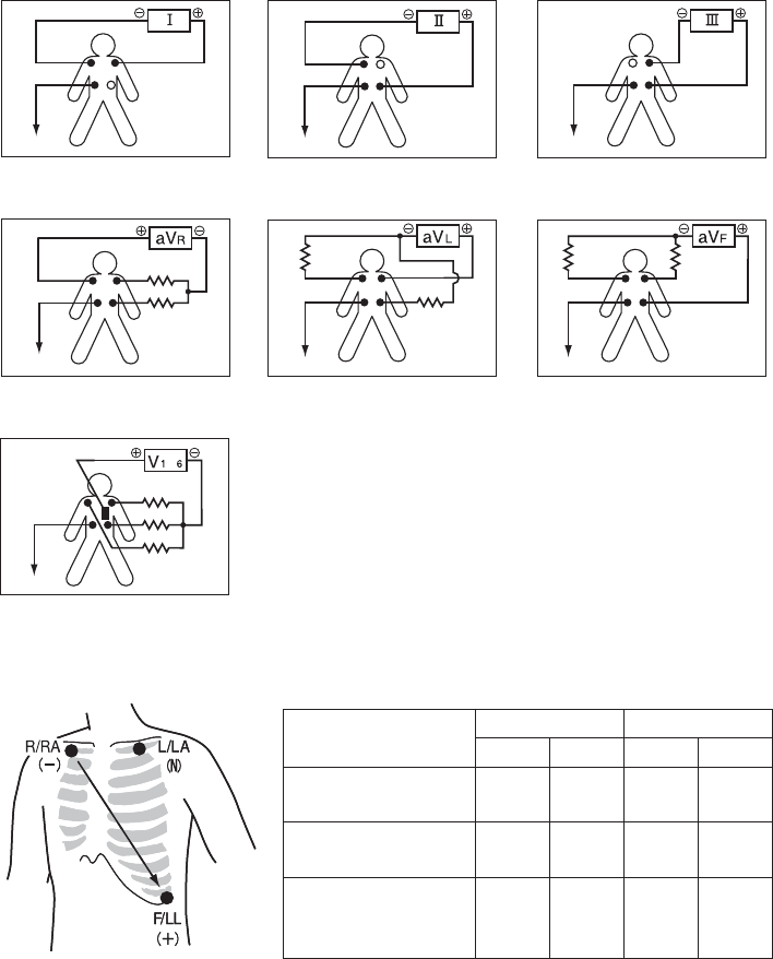
Lead Position
Standard limb leads
Monopolar limb leads
Monopolar chest leads
L
ea
d
I
Lead I Lead II Lead III
aVR lead aVL lead aVF lead
V
1 to V6 leadsV1 to V6 leads
to
RA
RA
RA RA RA
RA
RA
LA
LA
LA
LA
LA
LA
LA
LL
LL
LL
LL LL
LL
LL
N (RL)
N (RL)
N (RL) N (RL) N (RL)
N (RL)
N (RL)
Three Electrodes
• Lead MII, which is similar to standard lead II, used when ECG measurement has priority
Electrode Position Symbol Lead Color
AHA IEC AHA IEC
Left infraclavicular
fossa LA L Black Yellow
Right infraclavicular
fossa RA R White Red
Below lowest rib
on the left anterior
axillary line
LL F Red Green
Operator’s Manual ZM-540PA/541PA 43
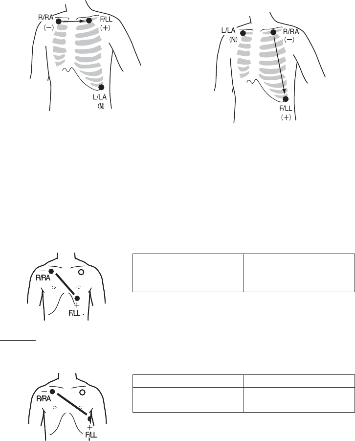
• Lead MI, which is similar to standard lead I
Change F/LL and L/LA of lead MII.
• Lead MIII, which is similar to standard lead
III
Change R/RA and L/LA of lead MII.
If the electrode positions above are not available due to chest surgery, attach the electrodes to the
root of the limbs or below the clavicles for stable ECG monitoring.
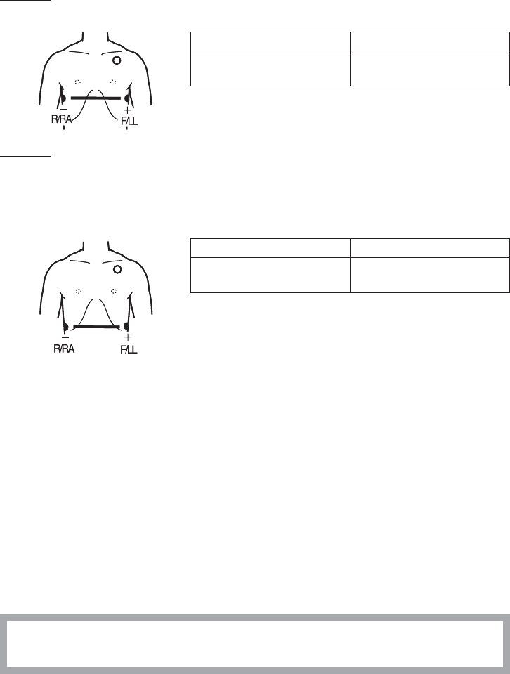
Electrode Positions for Respiration Monitoring
Place the R/RA and F/LL electrodes so that the lungs are between the electrodes.
Position 1
In this position, respiration measurement is available; however, there is a difference in amplitude
between different patients.
R or RA F or LL
Right infraclavicular fossa Fifth intercostal space on the
left midclavicular line, V4
Position 2
In this position, the waveform amplitude is usually large and the ECG lead is similar to Lead MII.
This position can be generally recommended.
R or RA F or LL
Right infraclavicular fossa Fifth intercostal space on the
left midaxillary line, V6
NN
NN
44 Operator’s Manual ZM-540PA/541PA
Position 3
In this position, the respiration waveform is optimum, but the ECG lead is unusual.
R or RA F or LL
Right midaxillary at the
horizontal level of V6
Fifth intercostal space on the
left midaxillary line, V6
Position 4
In this position, the respiration measurement is influenced by the impedance variation of the
abdomen, so the cardiac pulse wave included in the respiration wave is reduced. Note that the
waveform is inverted in phase compared with the chest movement (the waveform goes down during
inspiration). It is difficult to measure the ECG at the same time.
R or RA F or LL
Lowest rib on the right
anterior axillary line
Lowest rib on the left anterior
axillary line
Attaching Electrodes to the Patient and Connecting the Electrode Leads to
Disposable Electrodes
Prepare the Patient Skin
Shave off excessive body hair.
To reduce skin impedance, clean the electrode site with cream or with a cotton pad moistened with
alcohol. Thoroughly dry the skin with a clean cotton pad.
NOTE
• For a patient with frequent body movement, rub the sites with Skinpure skin preparation
gel. However, do not use Skinpure skin preparation gel on sensitive skin.
• Do not place electrodes on a wound or on an inflamed, wrinkled or uneven skin surface.
Attaching Electrodes to the Patient
CAUTION
Do not reuse disposable parts and accessories.
NOTE
• To maintain good contact between the electrode and skin, check that the paste of the
NN
NN
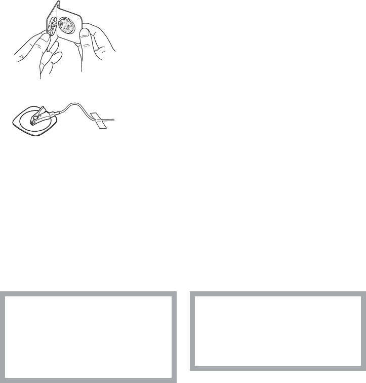
Operator’s Manual ZM-540PA/541PA 45
disposable electrode is not dry.
• When contact between the disposable electrode and skin becomes poor, replace
electrodes with new ones immediately. Otherwise, contact impedance between the skin
and the electrode increases and accurate ECG cannot be obtained.
Refer to the electrode operator’s manual for details.
1. Carefully remove the backing paper from the electrode.
Avoid touching the adhesive surface.
2. Place the electrode on the previously cleaned skin. Pay
attention to the electrode lead color and symbol.
3. Clip the electrode lead to the electrode.
4. Fasten the electrode lead wire with surgical tape with an
extra length of wire between the tape and the electrode.
This lessens the movement of electrode leads by body
movement and helps stable monitoring.
Checking ECG on the Transmitter Screen
After attaching electrodes and connecting ECG leads, check that the electrodes are properly attached
to the patient and the ECG waveform is acquired on the check electrodes screen. For details on the
screen, refer to the “Screen Descriptions” section.
Attaching the SpO2 Probe
Selecting the SpO2 Probe
Select an appropriate probe for the patient.
CAUTION
Only use Nihon Kohden specified
electrodes, electrode leads, SpO2
probes, and NIBP cuffs. Otherwise,
the maximum performance from the
transmitter cannot be guaranteed.
CAUTION
Do not use a damaged or
disassembled probe. It causes
incorrect measurement and may
injure the patient.
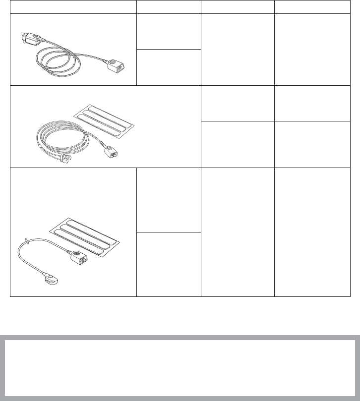
46 Operator’s Manual ZM-540PA/541PA
Reusable Probes
When using a TL-201T finger probe, choose the appropriate cable length for attachment.
Probe Cable Length Patient Attachment Site
Finger probe TL-201T
0.6 m
Adult or child
20 kg or more
Finger
1.6 m
Multi-site probe TL-220T
Attachment tape
Adult or infant
3 kg or more
Finger or toe
Neonate
3 kg or less
Instep and sole
Finger probe
TL-630T1, TL-630T3,
TL-631T1, TL-631T3
Attachment tape
TL-630T1, TL-
631T1: 0.6 m
TL-630T1/630T3:
Adult or child
50 kg or more
TL-631T1/631T3:
Adult or child
20 kg or more
Finger or toe
TL-630T3, TL-
631T3: 1.6 m
Disposable Probes
CAUTION
The disposable probe is not sterilized. Use the disposable probe only for a single
patient. Never reuse the disposable probe for another patient because it causes cross
infection.
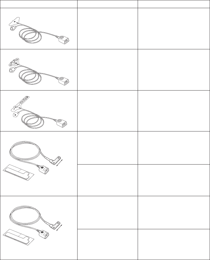
Operator’s Manual ZM-540PA/541PA 47
Probe Patient Attachment Site
TL-251T Adult
30 kg or more
Finger or toe
TL-252T Child
3 to 40 kg
Finger or toe
TL-253T Neonate
3 kg or less
Instep and sole
TL-051S, TL-052S
40 mm
Cable length TL-051S: 0.8 m
TL-052S: 1.6 m
Adult
50 kg or more
Finger
Neonate
3 kg or less
Instep and sole
TL-061S, TL-062S
35 mm
Cable length TL-061S: 0.8 m
TL-062S: 1.6 m
Adult or child
15 to 50 kg
Finger
Infant
3 to 15 kg
Toe

48 Operator’s Manual ZM-540PA/541PA
Probe Patient Attachment Site
TL-271T, TL-271T3
Cable length TL-271T: 0.8 m
TL-271T3: 1.6 m
Adult
30 kg or more
Finger or toe
TL-272T, TL-272T3
Cable length TL-272T: 0.8 m
TL-272T3: 1.6 m
Child
10 to 50 kg
TL-273T, TL-273T3
Cable length TL-273T: 0.8 m
TL-273T3: 1.6 m
Neonate
3 kg or less
Instep and sole
Adult
40 kg or more
Finger or toe
TL-274T, TL-274T3
Cable length TL-274T: 0.8 m
TL-274T3: 1.6 m
Infant
3 to 20 kg
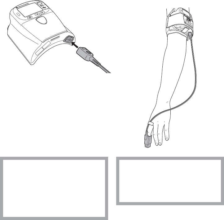
Operator’s Manual ZM-540PA/541PA 49
Connecting the SpO2 Probe to the Transmitter
Connect the probe to the SpO2 socket on the transmitter.
When transmitter is attached on an arm
CAUTION
Do not shake or swing the transmitter
while holding the leads or cables
connected to the transmitter. The
transmitter may come off and injure
someone or damage surrounding
instruments.
CAUTION
Do not use a damaged or
disassembled probe. It causes
incorrect measurement and may
injure the patient.
Attaching the Probe to the Patient
Attach the probe to the patient by referring to the probe’s manual. Make sure that the light emitter
and photo detector of the probe face each other at the attachment site.

50 Operator’s Manual ZM-540PA/541PA
WARNING
• When using the TL-201T finger
probe, do not fasten the probe and
cable to the finger by wrapping
with tape. This may cause burn,
congestion or pressure necrosis
from poor blood circulation.
• When using probes other than the
TL-201T finger probe, to avoid poor
circulation, do not wrap the tape too
tight. Check the blood circulation
condition by observing the skin
color and congestion at the skin
peripheral to the probe attachment
site. Even for short-term monitoring,
there may be burn or pressure
necrosis from poor blood circulation,
especially on neonates or low
birth weight infants whose skin is
delicate. Accurate measurement
cannot be performed on a site with
poor peripheral circulation.
WARNING
Check the circulation condition by
observing the skin color at the
measurement site and pulse
waveform. Change the measurement
site every 8 hours for disposable
probes and every 4 hours for reusable
probes (every 8 hours for TL-630T/TL-
631T series probe). The skin
temperature may increase at the
attached site by 2 or 3°C (4 or 5°F)
and cause a burn or pressure
necrosis. When using the probe on the
following patients, take extreme care
and change the measurement site
more frequently according to
symptoms and degree.
• Patient with a fever
• Patient with peripheral circulation
insufficiency
• Neonate or low birth weight infant
with delicate skin
WARNING
When monitoring SpO2 of a patient
who is receiving photodynamic
therapy, the light from the finger probe
sensor may cause a burn.
Photodynamic therapy uses a
photosensitizing agent that has a side
effect of photosensitivity.

Operator’s Manual ZM-540PA/541PA 51
CAUTION
If the attachment site is dirty with
blood or bodily fluids, clean the
attachment site before attaching the
probe. If there is nail polish on the
attachment site, remove the polish.
Otherwise, the amount of transmitted
light decreases, and measured value
may be incorrect or measurement
cannot be performed.
CAUTION
When the probe is attached on an
appropriate site with sufficient
circulation and the error message
confirming the probe attachment
repeatedly appears, the probe may be
deteriorated. Replace it with a new
one.
CAUTION
If the skin gets irritated or redness
appears on the skin from the probe,
change the attachment site or stop
using the probe. Take extreme care for
the patients with delicate skin.
CAUTION
Do not use a probe which is
deteriorated by aging. Accurate
measurement cannot be performed.
CAUTION
Refer to the probe instruction manual
for details.
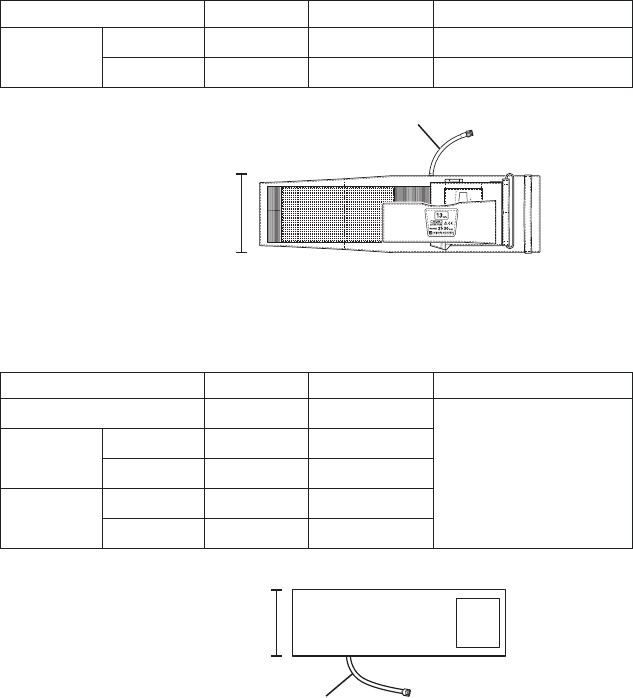
52 Operator’s Manual ZM-540PA/541PA
Attaching the NIBP Cuff
Selecting the NIBP Cuff
Select the NIBP cuff appropriate for the patient.
NOTE
NIBP cannot be measured on neonates using this transmitter.
Reusable Cuffs
When attaching the transmitter to the patient arm, a special NIBP cuff is required. An optional
YN-990P extension hose (1.5 m) is available to extend the length between the NIBP socket on the
transmitter and NIBP cuff (e.g. when not attaching the transmitter to the patient arm and placing the
transmitter on a bedside).
Reusable Cuff Model Width (cm) Air Hose Length (cm)
For adult Standard YP-503P 13 15
Large YP-504P 15 15
Width
Air hose
When not attaching the transmitter to the patient arm, the following cuffs can be used. To use these
cuffs, an optional YN-990P extension hose (1.5 m) is required.
Reusable Cuff Model Width (cm) Air Hose Length (cm)
For infant YP-960T 5
15
For child Small YP-961T 7
Standard YP-962T 10
For adult Standard YP-963T 13
Large YP-964T 15
Width
Air hose
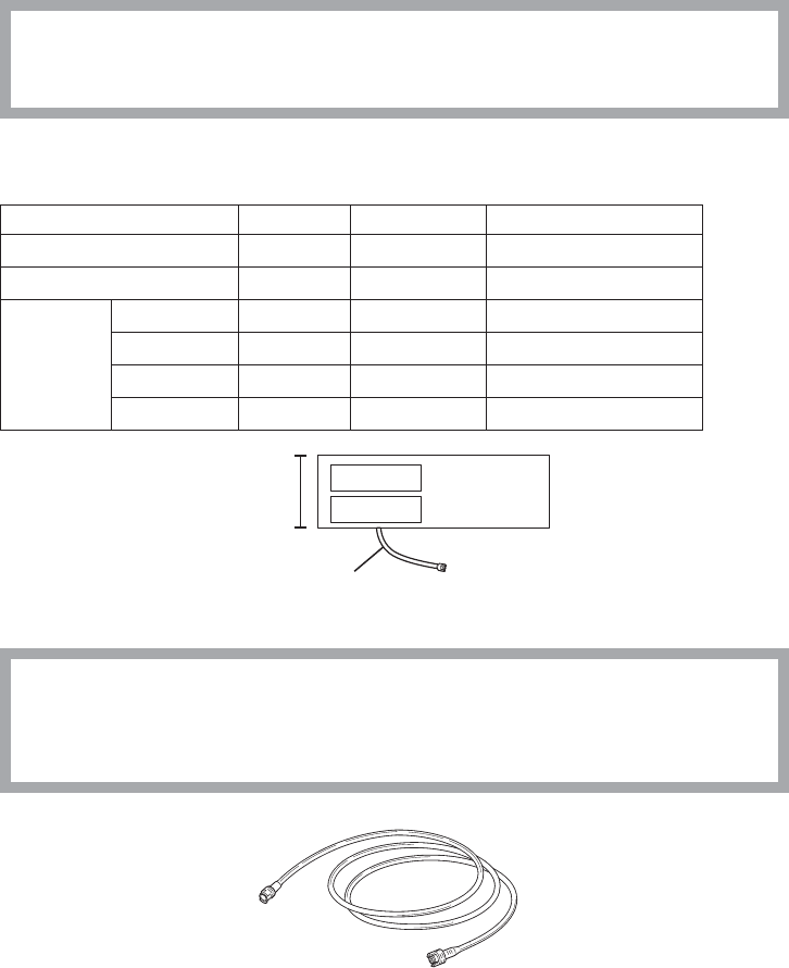
Operator’s Manual ZM-540PA/541PA 53
Disposable Cuffs
CAUTION
Disposable cuffs are not sterilized. If necessary, sterilize the cuff using glutaraldehyde
solution.
When not attaching the transmitter to the patient arm, the following disposable cuffs can be used.
To use these cuffs, an optional YN-990P extension hose (1.5 m) is required.
Reusable Cuff Model Width (cm) Air Hose Length (cm)
For infant YP-810P 6 17
For child YP-811P 8 17
For adult
Small YP-812P 10 17
Standard YP-813P 14 20
Medium large YP-814P 15 20
Large YP-815P 17 20
Width
Air hose
Extension Hose
CAUTION
When using an extension hose, check that the extension hose is not bent or
squeezed. Otherwise, the cuff might not inflate or deflate. If the cuff cannot deflate, it
may cause congestion on the patient at the cuff attachment site.
YN-990P extension hose, 150 cm
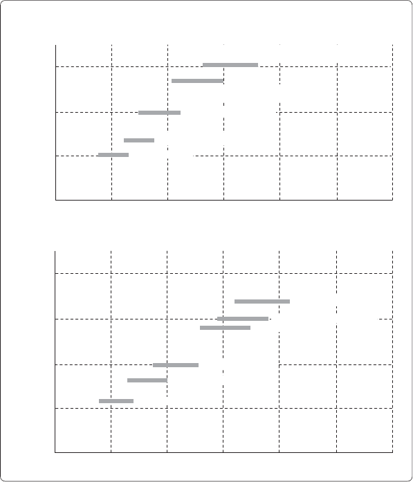
54 Operator’s Manual ZM-540PA/541PA
Reference for selecting a cuff
The AHA (American Heart Association) recommends that the cuff width be 40% of the
circumference of the upper arm. Refer to the following graph and select the cuff which suits the
patient’s arm.
NOTE
• If a range of arm circumference appropriate for the cuff is prescribed, use a cuff within
that range.
• To obtain accurate measured values, select a wide cuff which can be attached to the
upper arm. Measuring with a very narrow cuff may result in measured values higher than
the actual values.
• The YP-503P NIBP cuff is for standard size adult. Do not use this cuff when it does not fit
the patient.
15
10
5
10 20 30 40 50
0
20
15
10
5
10 20 30 40 50 60
0
60
Cuff width (cm)
Arm circumference (cm)
Infants YP-960T
Children small YP-961T
Children standard YP-962T
Adults standard YP-503P (cuff for transmitter)
YP-963T
Adults large YP-504P (cuff for transmitter)
YP-964T
Cuff Width and Arm Circumference
Reusable Cuffs
Cuff width (cm)
Arm circumference (cm)
Children standard YP-811P
Adults large YP-815P
Disposable Cuffs
Infants YP-810P
Adults small YP-812P
Adults standard YP-813P
Adults medium large YP-814P
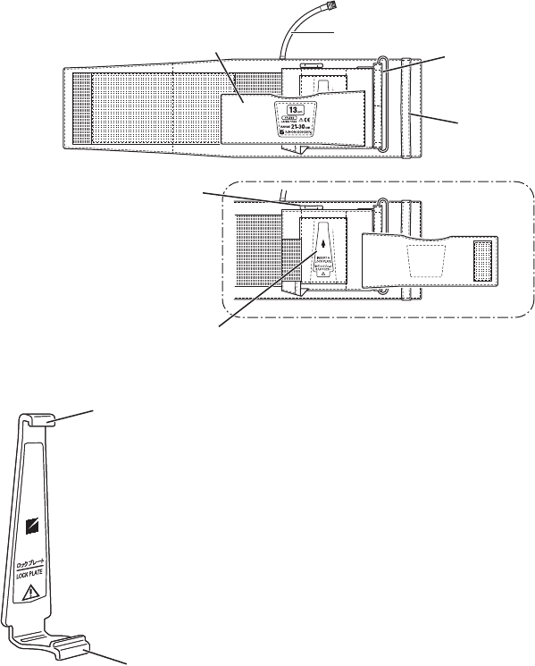
Operator’s Manual ZM-540PA/541PA 55
Connecting the NIBP Cuff to the Transmitter
When Using YP-503P/YP-504P NIBP Cuff
To attach the YP-503P/YP-504P NIBP cuff to the transmitter, the lock plate is required.
YP-503P/YP-504P NIBP cuff
Front cover Air hose
D ring
Belt
Belt for the strap
Lock plate pocket Front cover open
Lock plate
For attaching the NIBP cuff to the transmitter
NOTE
Do not roll up or put weight on the cuff when the lock plate is
attached to it. The lock plate may break if the cuff is rolled up or
weight is put on it when the lock plate attached.
Top tab
Bottom tab
Top tab
Bottom tab
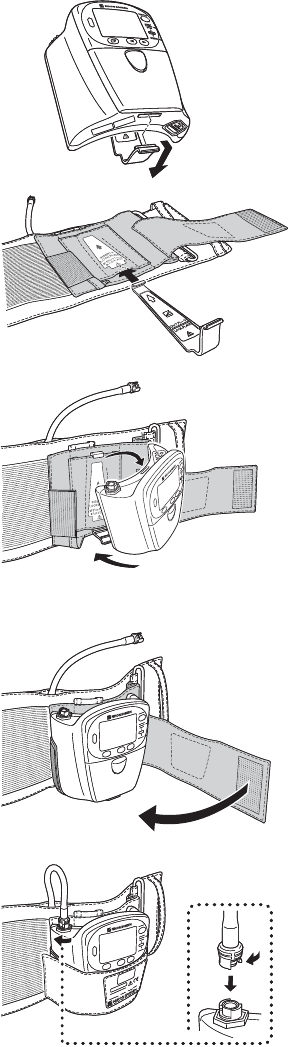
56 Operator’s Manual ZM-540PA/541PA
1. Remove the lock plate from the
transmitter.
2. Insert the lock plate into the lock
plate pocket on the NIBP cuff.
3. Attach the transmitter to the lock
plate by inserting the tabs on the
lock plate into the slots on the
transmitter.
4. Cover the transmitter with the
front cover of the NIBP cuff.
5. Connect the air hose to the NIBP
socket on the transmitter. Turn
the cuff connector joint until it
clicks.
1
2
1
2
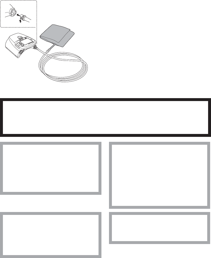
Operator’s Manual ZM-540PA/541PA 57
When Using Disposable Cuffs or YP-960T series Reusable Cuffs
To use these NIBP cuffs, an optional YN-990P extension hose (1.5 m) is required.
NOTE
Connect the joints properly. If there is an air leak, NIBP cannot be measured properly.
1. Connect the NIBP cuff to the extension hose.
2. Connect the other end of the extension hose
to the NIBP socket on the transmitter. Turn
the joint clockwise until it clicks.
To disconnect the cuff from the transmitter,
turn the hose joint counterclockwise.
Attaching the NIBP Cuff to the Patient
WARNING
Be careful when measuring NIBP on a patient with known bleeding disorders or
coagulation. After NIBP measurement, there may be dot hemorrhage, or circulatory
disorder by thrombus where the cuff is attached.
CAUTION
Do not wrap the cuff on an arm or
thigh which is used for injection. NIBP
measurement on an arm or thigh
which is used for injection may cause
reflux of blood and stop injection.
CAUTION
Do not attach the cuff to the site
where there is injury or inflammation.
If the skin gets irritated or redness
appears on the skin from the cuff,
change the attachment site or stop
using the cuff. Take extreme care on
the patients with delicate skin.
CAUTION
Do not wrap the cuff too tight. It may
cause poor blood circulation and
congestion. If the cuff is wrapped too
loosely, the NIBP value may increase.
CAUTION
Do not reuse disposable parts and
accessories.

58 Operator’s Manual ZM-540PA/541PA
CAUTION
NIBP and SpO2 can be measured on
the same limb, but the SpO2
monitoring might not be accurate
during NIBP measurement. Be careful
when reading the SpO2 values.*
* Monitoring SpO2 during NIBP Measurement
When the SpO2 probe is attached to the
same limb as the NIBP cuff, the blood
flow decreases during NIBP measurement
and pulse wave cannot be detected and
SpO2 cannot be monitored properly. When
“INHIBIT SpO2 DURING NIBP” on the
PARAMETER SETUP screen is set to ON
(factory default setting), SpO2 monitoring is
paused during NIBP measurement to avoid
SpO2 alarm occurrence. However, when
monitoring SpO2 on the same limb as the
NIBP, be careful when reading SpO2 values.
NOTE
• Measuring NIBP at a site other than the upper arm gives different values from those
measured at the upper arm. When making diagnosis based on the NIBP values, measure
NIBP on an upper arm.
• To accurately detect the pulsatile flow of the artery, the cuff should be wrapped around a
bare upper arm.
• Do not use an abnormal cuff. The cuff deteriorates from use and cleaning. Before use,
check the cuff and confirm that there is no flaw, crack or hole in it. Be careful not to
damage the inflation bag. If the inflation bag has a hole or a flaw, it may burst during use.
Dispose of an abnormal cuff and replace it with a new one.
• Refer to the NIBP cuff manual for details.
Cuff Position
Place the cuffed upper arm (brachium) at the same height
as the patient’s heart. If the cuff is not at the same level as
the heart, the weight of the blood affects the blood pressure
reading. The pressure difference per unit height is 0.7
mmHg/cm. The blood pressure reading decreases when the
arm is higher than the heart and increases when lower.
The best measuring condition is when the patient is lying on
his/her back with arms and legs relaxed. If the cuff position
cannot be on the same level as the heart, the displayed blood
pressure reading must be mathematically adjusted.
When placing the transmitter on
a bed, make sure that the hose is
not bent.
Heart
When placing the transmitter on
a bed, make sure that the hose is
not bent.
Heart
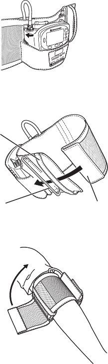
Operator’s Manual ZM-540PA/541PA 59
Attaching the Transmitter on an Arm (Using the YP-503P/504P NIBP Cuff)
1. Attach the NIBP cuff to the transmitter. Refer
to the “Connecting the NIBP Cuff to the
Transmitter” section.
2. Before putting the cuff over the arm, insert the
end of the cuff into the belt and then through the
D ring as shown at left.
3. Put the patient arm through the cuff. Fold back
the cuff at the D ring and fasten it using the
velcro tape.
Make sure that the cuff is not attached on a joint.
NOTE
The cuff must not wrap around the elbow.
Belt
D ring End of cuff
Belt
D ring End of cuff
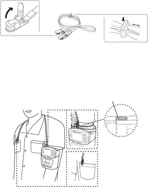
60 Operator’s Manual ZM-540PA/541PA
Attaching the Strap to the Transmitter
NOTE
• Use the strap to prevent the transmitter from falling.
• Do not attach the clip to hard objects such as thick cloth or zipper. It will break the clip.
Attach a strap provided with the transmitter to the NIBP cuff and patient clothes.
To open the clip, firmly
pull out the tab in
direction of the arrow. To adjust the strap length,
push down the tab on the
adjuster and slide.
1. Adjust the length of the strap.
2. Clip one end of the strap to the belt for the strap on the NIBP cuff.
3. Clip the other end of the strap to the patient’s clothes as shown left.
Belt for the strap on the NIBP cuff
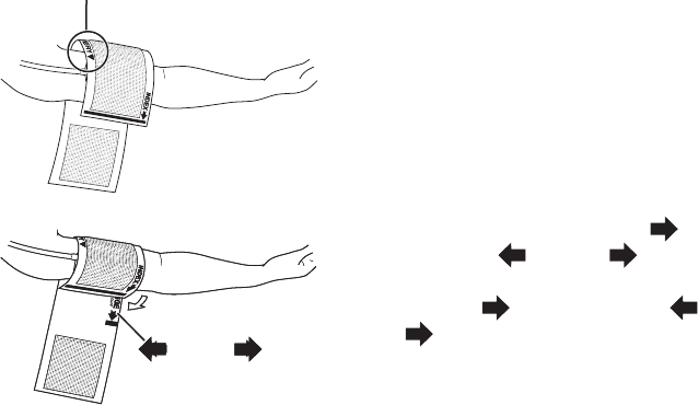
Operator’s Manual ZM-540PA/541PA 61
Placing the Transmitter on the Bed (Using the Disposable Cuffs or YP-960T series Reusable
Cuffs)
1. Put the cuff on the upper arm so that the ▼ mark
of “ARTERY ▼” aligns with the artery of the
patient.
ARTERY ▼
2. Wrap the cuff so that “INDEX ” comes
within the “ RANGE ”.
If “Index ” is not within the “ RANGE
”, change the cuff size.
RANGERANGE
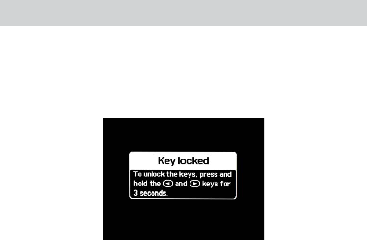
62 Operator’s Manual ZM-540PA/541PA
Locking the Keys on the Transmitter
To prevent the patient from pressing the keys on the transmitter during monitoring, you can lock the
keys.
Press the
▼
and
▼
keys at the same time and hold for more than 3 seconds. The key lock screen
appears.
When there is no key operation for one minute after locking the keys, the display turns off.
To unlock the keys:
Press the
▼
and
▼
keys at the same time and hold for more than 3 seconds.
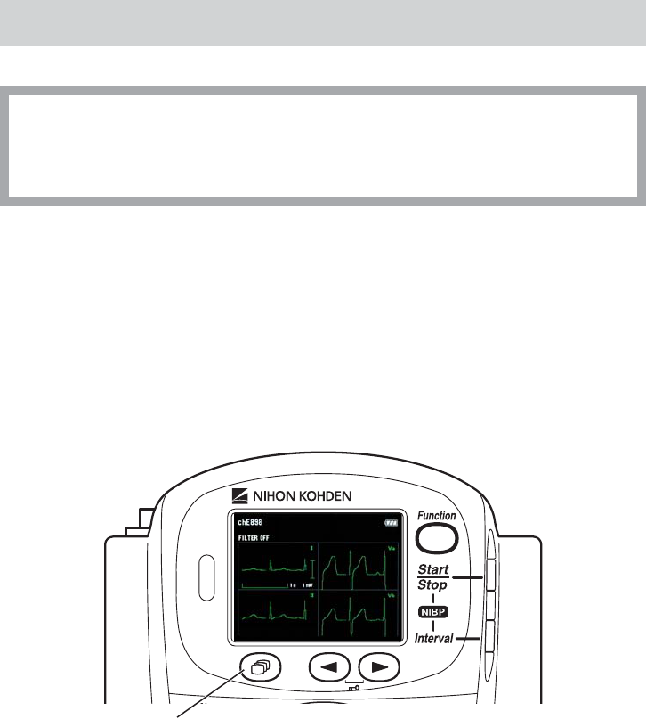
Operator’s Manual ZM-540PA/541PA 63
Monitoring
CAUTION
The measurement values and displayed waveforms on the transmitter and receiving
monitor may be different due to timing delay of the display or difference in detection
settings.
Screen Descriptions
When the transmitter is turned on, the startup screen appears, then the check electrodes screen
appears to check the electrode attachment.
The screen changes in the following order each time the Screen key is pressed.
Check electrodes → numeric and waveform → waveform review → numeric review → display off→ numeric and waveform → waveform review → numeric review → display off numeric and waveform → waveform review → numeric review → display off→ waveform review → numeric review → display off waveform review → numeric review → display off→ numeric review → display off numeric review → display off→ display off display off
→ check electrodes . . . check electrodes . . .
Screen key
The screen automatically turns off when there is no key operation for 2 minutes on the check
electrodes screen or 1 minute on other screens.
When the display is off and the Screen key is pressed, the numeric and waveform screen appears.
When the Screen key is pressed within 5 minutes after the display off, the screen before the display
off appears.
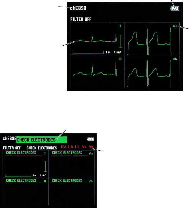
64 Operator’s Manual ZM-540PA/541PA
Check Electrodes Screen
You can check whether the electrodes are properly attached to the patient and the ECG waveform is
acquired.
When 6 leads are used, I, II, Va and Vb lead waveforms are displayed.
When 3 leads are used, only II lead waveform is displayed.
Channel number
Battery level
ECG waveform
Filter: off
Sweep speed: 12.5 mm/s
Waveform sensitivity: 0.5 cm/1 mV
Lead
Detached
electrode position
Message
When electrodes are
detached, the “CHECK
ELECTRODES”
message and detached
electrode position appear
on the screen.
NOTE
When ECG measurement is set to OFF on the PARAMETER SETUP screen, the check
electrodes screen does not appear.
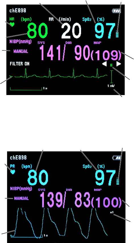
Operator’s Manual ZM-540PA/541PA 65
Numeric and Waveform Screen
Numeric values and waveforms of the monitoring parameters are displayed. You can change the
ECG lead with the
▼
and
▼
keys.
Heart rate
QRS sync mark
Pulse bar graph
SpO2
Respiration rate
NIBP values
ECG waveform
Filter: on
Sweep speed: 12.5 mm/s
Waveform sensitivity: auto
Waveform
sensitivity
ECG lead
NIBP measurement
mode
When ECG and respiration measurement is turned off
Pulse rate
Pulse sync mark
Pulse bar graph
SpO2
Pulse wave
sensitivity
Pulse waveform
Sweep speed: 12.5 mm/s
Waveform sensitivity: auto
NIBP values
NIBP measurement
mode
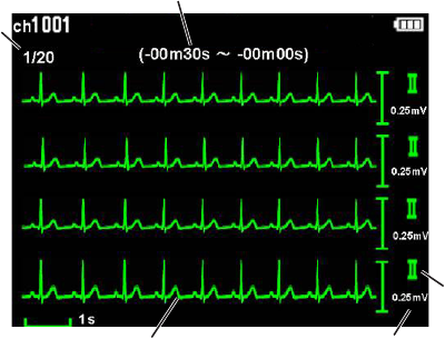
66 Operator’s Manual ZM-540PA/541PA
NOTE
The pulse wave amplitude varies according to the ratio of the pulsation component to the
entire transmitted IR signal. When the pulsation component ratio is 1%, the pulse wave
amplitude is about 5 mm at ×1 sensitivity on the screen.
Waveform Review Screen
ECG full disclosure for up to 10 minutes can be saved and reviewed. When ECG measurement is
turned off and SpO2 is monitored, the pulse waveform is saved.
When ECG lead is changed on the numeric and waveform screen, the ECG full disclosure of the
changed lead is saved.
The saved data is deleted when the transmitter is turned off.
ECG lead
Displayed
page
Compressed ECG waveform
7.5 s x 4 traces per page, total of 20 pages
Older data
Newer data
Time range of the displayed waveform
(time before the waveform review
screen is displayed)
Waveform sensitivity
To scroll the waveform, press the
▼
or
▼
key. The waveform is scrolled by 30 seconds.
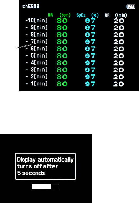
Operator’s Manual ZM-540PA/541PA 67
Numeric Review Screen
Numeric data of heart rate (or pulse rate when ECG is turned off), SpO2 and respiration rate for up
to 10 minutes are saved at 1 minute intervals.
NOTE
NIBP measured values are not saved.
The saved data is deleted when the transmitter is turned off.
Time before the numeric
review screen is displayed
Older data
Newer data
Display Off
The display can be turned off any time. To turn off the display, press the Screen key several times
until the following screen appears then wait 5 seconds.
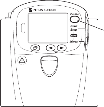
68 Operator’s Manual ZM-540PA/541PA
Basic Monitoring Operation
Using the Function Key
Function key
One of the following functions can be assigned to the Function key on the SYSTEM SETUP screen.
Refer to the “Changing SYSTEM SETUP Settings” section.
SUSPEND ALARM: Suspends alarms on the receiving monitor before they occur for 2 minutes.
PAUSE: Pauses monitoring on the transmitter and receiving monitor.
CONFIRM: Transmits the signal that the patient is confirmed and displays the “PATIENT
CONFIRMED” message on the transmitter.
NOTE
To use the Function key for PAUSE or CONFIRM, you must set “PROTOCOL” on the
SYSTEM SETUP screen of the transmitter to 57 and the receiving monitor must be able to
receive protocol 57.
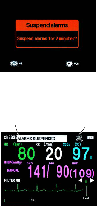
Operator’s Manual ZM-540PA/541PA 69
Suspending Alarms on the Receiving Monitor
When the FUNCTION KEY is set to “SUSPEND ALARM” or “SUSPEND ALARM & PAUSE”
on the SYSTEM SETUP screen, alarms can be suspended for 2 minutes on the receiving monitor
before they occur.
To suspend alarms:
1. Press the Function key. The “Suspend alarms” confirmation screen appears.
2. Press the
▼
key to suspend alarms.
To cancel suspending alarms and return to the previous screen, press the Screen key.
When the alarms are suspended, the “ALARMS SUSPENDED” message and alarm suspended icon
with the remaining minutes in alarm suspension appear on the transmitter screen.
Message Icon
To cancel suspending alarms during 2 minute alarm suspension:
1. Press the Function key while the “ALARMS SUSPENDED” message is displayed. The
confirmation screen appears.
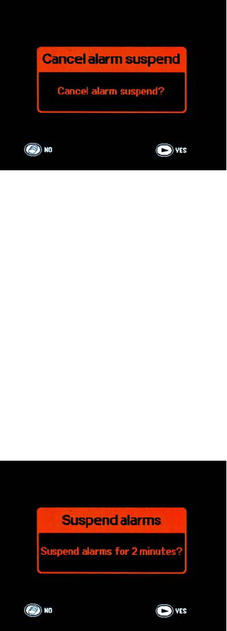
70 Operator’s Manual ZM-540PA/541PA
2. Press the
▼
key to cancel alarm suspension.
Press the Screen key to not cancel alarm suspension.
Pause Monitoring
When the FUNCTION KEY is set to “SUSPEND ALARM & PAUSE” on the SYSTEM SETUP
screen, you can pause monitoring on the receiving monitor from the transmitter when the patient
cannot be monitored, such as during X-ray examination.
NOTE
To use the Function key for PAUSE, you must set “PROTOCOL” on the SYSTEM SETUP
screen of the transmitter to 57 and the receiving monitor must be able to receive protocol
57.
To pause monitoring:
1. Press the Function key. The “Suspend alarms” confirmation screen appears.
2. Press the Function key for 3 seconds to display the “Pause monitoring” confirmation screen.
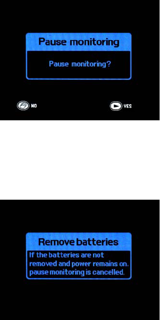
Operator’s Manual ZM-540PA/541PA 71
3. Press the
▼
key to pause monitoring.
To cancel pause monitoring, press the Screen key.
4. Wait about 5 seconds until the “Turn power off” screen appears.
5. Turn off the transmitter.
If the transmitter is not turned off and monitoring continues for the interval set for “AUTO
RESUME AFTER PAUSE” on the SYSTEM SETUP screen, pause monitoring is cancelled and
monitoring continues.
Resume Monitoring after Pause
To resume monitoring after pause, check that the electrodes, electrode leads and probe are attached
to the patient then turn on the transmitter.
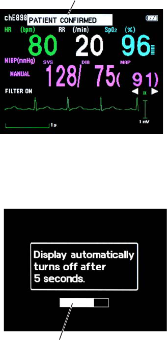
72 Operator’s Manual ZM-540PA/541PA
Confirming Patient
When the FUNCTION KEY is set to “CONFIRM” on the SYSTEM SETUP screen, you can
transmit signal to the receiving monitor to indicate that the patient is confirmed by a medical staff by
pressing the Function key.
Message
Turning the Display Off
The display can be turned off any time. To turn off the display, press the Screen key several times
until the following screen appears then wait 5 seconds.
5 second time bar until the display turns off
Turning the Display On after It was Turned Off
Press the Screen key. The numeric and waveform screen appears. If the screen is turned off on the
“Keys locked” screen, the “Keys locked” screen appears.
When the Screen key is pressed within 5 minutes after the display was turned off, the previous
screen appears.
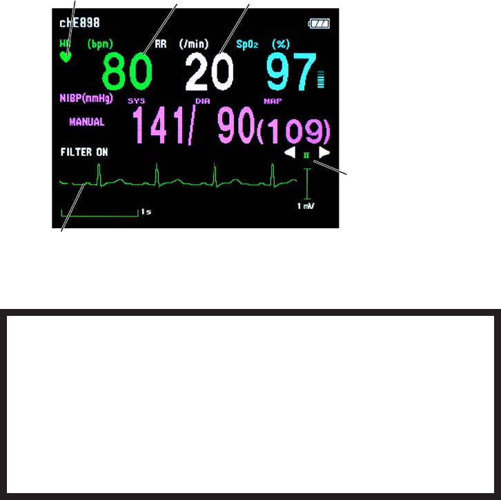
Operator’s Manual ZM-540PA/541PA 73
ECG and Respiration Monitoring
When the electrodes are attached and the ECG leads are connected, the heart rate, ECG waveform,
respiration rate and respiration waveform appear on the receiving monitor. Refer to the operator’s
manual of the receiving monitor for details.
When 6 leads are used on this transmitter, up to 8 lead (I, II, III, aVR, aVL, aVF, Va and Vb) of
ECG waveforms can be displayed on the receiving monitor. The heart rate is also measured.
When 3 leads are used, one channel ECG waveform of lead II can be displayed on the receiving
monitor. Refer to the operator’s manual of the monitor for details.
Heart rate
QRS sync mark Respiration rate
ECG lead
You can change the
ECG lead with the
▼
and
▼
keys.
ECG waveform Filter: on
Sweep speed: 12.5 mm/s
Waveform sensitivity: auto
WARNING
Interaction Between Minute Ventilation Rate-Adaptive Pacemakers and Cardiac
Monitoring and Diagnostic Equipment*
The bioelectric impedance measurement sensor of a minute ventilation rate-adaptive
implantable pacemaker may be affected by transmitter which is connected to the
same patient. If this occurs, the pacemaker may pace at its maximum rate and the
transmitter may give incorrect data to the monitor. If this occurs, disconnect the
electrode leads from the patient or change the setting on the pacemaker by referring
to the pacemaker’s manual. For more details, contact your pacemaker representative
or Nihon Kohden representative.
* Minute ventilation is sensed in rate-adaptive pacemakers by a technology known as bioelectric

74 Operator’s Manual ZM-540PA/541PA
impedance measurement (BIM). Many medical devices in addition to pacemakers use this
technology. When one of these devices is used on a patient with an active, minute ventilation rate-
adaptive pacemaker, the pacemaker may erroneously interpret the mixture of BIM signals created
in the patient, resulting in an elevated pacing rate.
For more information, see the FDA web site.
http://www.fda.gov/cdrh/safety.html
WARNING
When the transmitter is used with an electrosurgical unit (ESU), firmly attach the
entire area of the ESU return plate. Otherwise, the current from the ESU flows into the
electrodes of the transmitter, causing electrical burn where the electrodes are
attached. For details, refer to the ESU manual.
CAUTION
Turn off the power of mobile phones, small wireless devices and other devices which
produce strong electromagnetic interference around a patient (except for devices
allowed by the hospital administrator). Radio waves from devices such as mobile
phones or small wireless devices may be mistaken as pulse waves and the displayed
data may be incorrect.
NOTE
• Noise generated from an electrosurgical unit may interfere on an ECG waveform, but will
not damage it.
• If an electric blanket is used and incorrect heart rate is displayed on the monitor, turn off
the pacing spike detection on the monitor.
• Turn the pacing spike detection to ON on the receiving monitor when monitoring a
pacemaker patient. Pacing pulse is detected by the transmitter and transmitted to the
monitor. If the pacing spike detection is turned OFF, QRS and pacemaker spike might not
be distinguished and pacemaker failure might not be recognized.
• ECG cannot be monitored on a neonate using this transmitter.

Operator’s Manual ZM-540PA/541PA 75
Turning ECG Measurement On/Off
ECG measurement can be turned on or off on the PARAMETER SETUP screen. When electrodes
are attached to the patient and ECG leads are connected, ECG monitoring starts even when ECG is
turned off.
When PROTOCOL on the SYSTEM SETUP screen is set to 57:
ECG measurement on the receiving monitor is automatically set to off.
NOTE
ECG measurement on the transmitter cannot be turned on or off from the receiving
monitor.
When PROTOCOL on the SYSTEM SETUP screen is set to 42:
If ECG measurement is turned off on the transmitter, ECG measurement on the receiving monitor
must also be turned off.
Turning Respiration Measurement On/Off
Respiration measurement can be turned on or off on the PARAMETER SETUP screen. If respiration
measurement is turned off, respiration measurement on the receiving monitor is also turned off.
Electrode Detachment
In the following conditions, the “CHECK ELECTRODES” message is displayed on the transmitter
and receiving monitor.
• Electrode is detached from skin.
• Electrode lead is disconnected from the electrode.
• Polarization voltage between the electrode and skin is excessively high.
In these cases, check the cause and if necessary, replace electrodes with new ones.
CAUTION
When the “ELECTRODE OFF” or “CHECK ELECTRODES” message is displayed on
the receiving monitor, ECG is not monitored properly and the ECG alarm does not
function. Check the electrode, electrode leads, and if necessary, replace with new
ones.
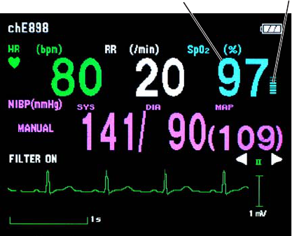
76 Operator’s Manual ZM-540PA/541PA
SpO2 Monitoring
When monitoring starts, SpO2 and pulse waveform are sent to the monitor and SpO2 and pulse level
bar graph are displayed on the transmitter screen. When ECG is not measured, pulse waveform and
pulse rate are also displayed.
Pulse bar graphSpO2
Filter: on
Sweep speed: 12.5 mm/s
Waveform sensitivity: auto

Operator’s Manual ZM-540PA/541PA 77
WARNING
SpO2 measurement may be incorrect
in the following cases.
• When the patient’s
carboxyhemoglobin or
methemoglobin increases
abnormally.
• When dye is injected in the blood.
• When using an electrosurgical unit.
• During CPR.
• When measuring at a site with
venous pulse.
• When there is body movement.
• When the pulse wave is small
(insufficient peripheral circulation).
WARNING
Check the circulation condition by
observing the skin color at the
measurement site and pulse
waveform. Change the measurement
site every 8 hours for disposable
probes and every 4 hours for reusable
probes (every 8 hours for TL-630T/TL-
631T series probe). The skin
temperature may increase at the
attached site by 2 or 3°C (4 or 5°F)
and cause a burn or pressure
necrosis. When using the probe on the
following patients, take extreme care
and change the measurement site
more frequently according to
symptoms and degree.
• Patient with a fever
• Patient with peripheral circulation
insufficiency
• Neonate or low birth weight infant
with delicate skin
WARNING
When monitoring SpO2 of a patient
who is receiving photodynamic
therapy, the light from the finger probe
sensor may cause a burn.
Photodynamic therapy uses a
photosensitizing agent that has a side
effect of photosensitivity.
WARNING
When not monitoring SpO2,
disconnect the SpO2 cable from the
transmitter. Otherwise, noise from the
probe sensor may interfere and
incorrect data is displayed on the
screen.

78 Operator’s Manual ZM-540PA/541PA
CAUTION
Turn off the power of mobile phones,
small wireless devices and other
devices which produce strong
electromagnetic interference around a
patient (except for devices allowed by
the hospital administrator). Radio
waves from devices such as mobile
phones or small wireless devices may
be mistaken as pulse waves and the
displayed data may be incorrect.
CAUTION
Do not pull or bend the probe cable,
and do not put caster feet on the
probe cable. Do not immerse the
disposable probe cable in chemical
solutions or water. Failure to follow
these instructions may cause cable
discontinuity, short circuit, skin burn
on the patient and incorrect
measurement data. Replace any
broken probe with a new one.
CAUTION
Normal external light does not affect
monitoring but strong light such as a
surgical light or sunlight may affect
monitoring. If affected, cover the
measuring site with a blanket.
CAUTION
When the probe is attached on an
appropriate site with sufficient
circulation and the error message
confirming the probe attachment
repeatedly appears, the probe may be
deteriorated. Replace it with a new
one.
CAUTION
When a message indicates a faulty
probe, stop monitoring and replace
the probe with a new one.
CAUTION
While a patient is on medication which
causes vasodilation, the pulse
waveform may change and in rare
cases the SpO2 value might not be
displayed.
NOTE
In order to maintain sufficient blood circulation, keep the measurement site warm by
covering it with a blanket or something similar. Warming the site is effective, especially for a
patient with a small pulse amplitude.

Operator’s Manual ZM-540PA/541PA 79
Monitoring SpO2 during NIBP Measurement
CAUTION
NIBP and SpO2 can be measured on the same limb, but the SpO2 monitoring might
not be accurate during NIBP measurement. Be careful when reading the SpO2 values.
When the SpO2 probe is attached to the same limb as the NIBP cuff, the blood flow decreases
during NIBP measurement and pulse wave cannot be detected and SpO2 cannot be monitored
properly. When “INHIBIT SpO2 DURING NIBP” on the PARAMETER SETUP screen is set to ON
(factory default setting), SpO2 monitoring is paused during NIBP measurement to avoid SpO2 alarm
occurrence. However, when monitoring SpO2 on the same limb as NIBP, be careful when reading
SpO2 values.
When monitoring SpO2 is important, attach the probe to the limb to which the NIBP cuff or catheter
is not attached.
When SpO2 monitoring is paused during NIBP measurement, the SpO2 value just before the start of
NIBP measurement and an mark are displayed on the transmitter for 30 seconds.
When NIBP measurement is not completed after 30 seconds, “– – –” is displayed for the SpO2 value.
The same data also appears on the monitor screen.
NOTE
• When continuous SpO2 monitoring is necessary, attach the probe to the limb to which the
NIBP cuff is not attached and set “INHIBIT SpO2 DURING NIBP” on the PARAMETER
SETUP screen to OFF.
• When the probe is attached to the same limb as the NIBP cuff, set the sync source to a
parameter other than SpO2 on the receiving monitor.
• When monitoring SpO2 during STAT NIBP measurement, attach the probe to the limb to
which the NIBP cuff is not attached.
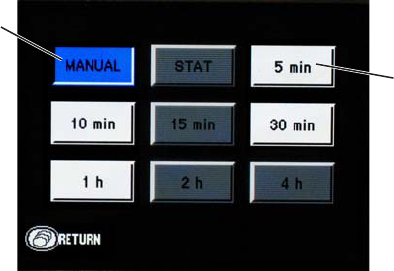
80 Operator’s Manual ZM-540PA/541PA
NIBP Monitoring
Selecting the Initial Cuff Inflation Pressure
The initial cuff inflation pressure can be changed on the PARAMETER SETUP screen. The default
setting is 180 mmHg. To change the setting, refer to the “Changing PARAMETER SETUP Settings”
section.
Selecting the Measurement Mode and Interval
Measurement Modes
There are three measurement modes: manual, auto and STAT. The selected mode or interval is
displayed on the screen.
The measurement mode and interval can be changed by pressing the NIBP Interval key.
When the key is pressed, the NIBP mode setting screen appears. The measurement modes selected
at “SELECTABLE INTERVALS” on the PARAMETER SETUP screen are displayed (key color:
white). Select the measurement mode with the
▼
and
▼
keys or NIBP Interval key and press the
Function key.
Selected mode
(key color: blue)
Modes selected
at “SELECTABLE
INTERVALS” on the
PARAMETERS SETUP
screen
(key color: white)
To select the modes to be displayed on the NIBP mode setting screen, refer to the “Changing
PARAMETER SETUP Settings” section.
Manual Measurement
In Manual mode, a single NIBP measurement is performed when the NIBP Start/Stop key is pressed.
STAT (Continuous) Measurement
In STAT mode, measurement is continuously repeated for 15 minutes after the NIBP Start/Stop key
is pressed.
When the STAT measurement for 15 minutes is completed, the measurement mode automatically
changes to the Manual mode or Auto mode of selected interval depending on the “NIBP MODE

Operator’s Manual ZM-540PA/541PA 81
AFTER STAT” setting on the PARAMETER SETUP screen. The default setting is Manual mode.
Refer to the “Changing Parameter Setup Settings” section.
The STAT measurement completes within 15 minutes. When more than 12 minutes elapse from the
start of measurement, there will be no more measurement performed and the measurement mode
changes to the mode selected for “NIBP MODE AFTER STAT” on the PARAMETER SETUP
screen.
Auto Measurement
In Auto mode, measurement is performed automatically at the preset time intervals.
In Auto mode, a single measurement can be performed by pressing the NIBP Start/Stop key between
auto measurements.
Measuring NIBP
WARNING
Be careful when measuring NIBP on a
patient with known bleeding disorders
or coagulation. After NIBP
measurement, there may be dot
hemorrhage, or circulatory disorder by
thrombus where the cuff is attached.
WARNING
NIBP measurement may be incorrect
in the following cases.
• When using an electrosurgical unit
• When there is body movement
• When the pulse wave is small
(insufficient peripheral circulation)
• Too many arrhythmias
• When there is vibration
• When there is a rapid blood
pressure change
• During CPR
WARNING
When performing NIBP
measurements in STAT mode or 5
minute intervals, periodically remove
the cuff from the patient for ventilation.
The skin temperature may increase at
the cuff attachment site by 2 or 3°C (4
or 5°F). When measuring a patient
with a fever or peripheral circulation
insufficiency, it may cause a burn.
CAUTION
When performing NIBP measurement
repeatedly, have a rest between
measurements to recover adequate
circulation.
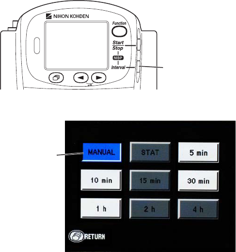
82 Operator’s Manual ZM-540PA/541PA
NOTE
• When measuring patients who are conscious, help the patient to relax. Measurement
may not be accurate if the patient’s arm is tense or if the patient talks.
• The data for measurement on a leg tends to be higher than measurement on the arm.
When making diagnosis based on the NIBP values, measure NIBP on an upper arm.
• Do not apply pressure to the cuff or air hose. NIBP may not be measured correctly
because of noise or NIBP measurement may stop due to the NIBP safety circuit.
• When the transmitter is attached to the patient arm and the NIBP measurement
is performed when moving, tell the patient to relax and keep quiet. Otherwise,
measurement may be stopped or remeasurement is repeated due to body movement.
• If there is an abnormal noise generated during measurement, stop using the transmitter
and contact your Nihon Kohden representative.
• Do not measure NIBP of a patient on whom an IABP is being used. Measurement may
be incorrect due to the mixing of the patient’s own pulse and IABP pulse.
• NIBP cannot be measured on a neonate using this transmitter.
1. Press the NIBP Interval key to display the NIBP mode setting screen.
NIBP Interval key
2. Select the measurement mode by pressing the NIBP Interval key or
▼
and
▼
keys.
Selected mode
(key color: blue)
3. Press the Function key.
4. Press the NIBP Start/Stop key to perform measurement.
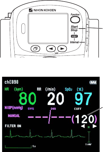
Operator’s Manual ZM-540PA/541PA 83
NIBP Start/Stop key
The cuff is inflated and the inflation pressure is displayed on the screen.
Inflation pressure
In manual mode: Measurement is performed once.
In STAT mode: Measurement is performed repeatedly for 15 minutes.
In auto mode: The first measurement is performed when the NIBP Start/Stop key is
pressed. The second measurement is performed when the current time in the
transmitter reaches the selected time interval.
To stop measurement during measurement, press the NIBP Start/Stop key again.
In STAT mode, after completing the STAT measurement, the measurement mode changes to the
mode set for “NIBP MODE AFTER STAT” on the PARAMETER SETUP screen.
In auto mode, to stop measurement in auto mode, change the mode to manual. To cancel one
measurement, press the NIBP Start/Stop key during measurement.
After the measurement is complete, the measured data is displayed on the screen and is transmitted
to the monitor.
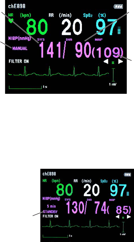
84 Operator’s Manual ZM-540PA/541PA
Systolic value Diastolic value
MAP value
NIBP measurement
mode
When ECG and SpO2 are not monitored (ECG measurement is turned off and SpO2 probe is not
connected to the transmitter), the pulse rate at the end of NIBP measurement is displayed.
A buzzer can be set to sound at the start and end of NIBP measurement. Refer to the “Changing
PARAMETER SETUP Settings” section.
Auto Mode Measurement
When auto mode measurement is selected, “STANDBY” message is displayed on the screen until
the NIBP Start key is pressed for the first time.
STANDBY message
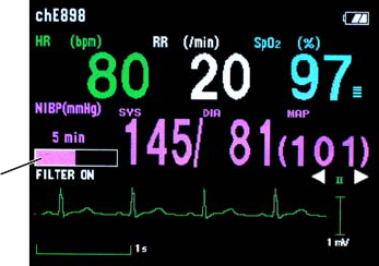
Operator’s Manual ZM-540PA/541PA 85
A time bar appears to indicate the interval between auto mode measurements.
Time bar indicating
the interval between
measurements
During auto mode measurement, the measurement mode can be changed. During the interval, press
the NIBP Interval key to change the mode. When “MANUAL” is displayed for more than one
second, the measurement in auto mode is stopped.
Data Display After NIBP Measurement
When the time set at “OLD NIBP DATA” on the PARAMETER SETUP screen elapses after the last
measurement, the NIBP data is dimmed or hidden. Whether to dim or hide the old data can also be
selected at “OLD NIBP DATA”. Refer to the “Changing PARAMETER SETUP Settings” section.
Data Display on the Receiving Monitor
When the “BATTERY” message is displayed on the receiving monitor, NIBP might not have
been measured according to the NIBP interval setting. Therefore, the NIBP data displayed on the
receiving monitor might not be updated. In this case, check the measurement time of the NIBP data
displayed on the receiving monitor.
Monitoring SpO2 during NIBP Measurement
When the SpO2 probe is attached to the same limb as the NIBP cuff, the blood flow decreases
during NIBP measurement and pulse wave cannot be detected and SpO2 cannot be monitored
properly. When “INHIBIT SpO2 DURING NIBP” on the PARAMETER SETUP screen is set to
ON (factory default setting), SpO2 monitoring is paused during NIBP measurement to avoid SpO2
alarm occurrence. However, when monitoring SpO2 on the same limb as the NIBP, be careful when
reading SpO2 values.
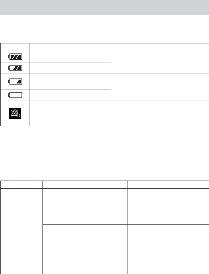
86 Operator’s Manual ZM-540PA/541PA
Indication and Message List
Indication
Indication Cause Countermeasure
Fully charged batteries
——
Batteries are 2/3 full.
Batteries are low. NIBP cannot be
measured. Replace batteries.
Batteries are very weak.
Alarms on the receiving monitor
were suspended by pressing the
Function key on the transmitter.
Alarms resume when the suspend interval
elapses. To cancel alarm suspension, press
the Function key again.
Messages
When PROTOCOL on the SYSTEM SETUP screen is set to 57, all messages are transmitted.
When PROTOCOL is set to 42, the messages marked with * are not transmitted.
Message Cause Countermeasure
AIR LEAK
The cuff and extension hose are not
properly connected.
Connect them properly.
The cuff hose (or extension hose) is
not properly connected to the NIBP
socket.
The cuff or extension hose is damaged. Replace with a new one.
ALARMS
SUSPENDED
Alarms on the receiving monitor is
suspended by pressing the Function
key on the transmitter.
Alarms resume when the 2 minute
suspend interval elapses. To cancel
alarm suspension, press the Function
key again.
BATTERY
WEAK Dead batteries Replace batteries.

Operator’s Manual ZM-540PA/541PA 87
Message Cause Countermeasure
CANNOT
DETECT
PULSE*
(displayed in blue)
Poor blood circulation for measuring
the SpO2 value.
Check the patient condition, probe
attachment or change the attachment
site.
The probe is attached too tightly and is
obstructing the blood circulation. Reattach the probe.
The probe is not attached to the patient
properly.
Attach the probe to the patient
properly.
“LIGHT INTERFERENCE”,
“CHECK PROBE SITE” or
“DETECTING PULSE” message is
displayed for more than 30 seconds.
Refer to the cause and
countermeasure for each message in
this Messages table and remove the
cause.
CANNOT
DETECT PULSE
(displayed in pink)
The patient’s pulse wave is too small
to measure NIBP. Measure by palpation or auscultation.
The cuff is not wrapped on the patient
properly. Wrap the cuff on the patient properly.
CHECK
ELECTRODES
Electrode lead is disconnected from
the electrode.
Firmly connect the electrode lead to
the electrode.
Electrode lead is disconnected from
the transmitter.
Firmly connect the electrode lead to
the transmitter.
Electrode lead discontinuity. Replace the electrode lead with a
new one.
Electrode is not firmly attached to the
skin. Replace the electrode with a new
one.
Polarization voltage is abnormally
high.
CHECK PROBE
The probe is not attached to the patient
properly.
Attach the probe to the patient
properly.
The probe is not attached at the
appropriate site.
Attach the probe to an appropriate
site indicated in the probe manual.
The probe is disconnected from the
transmitter.
Connect the probe cable to the
transmitter.
The probe is past its expiration date. Replace the probe with a new one.
CHECK PROBE
SITE*
The probe is not attached at the
appropriate site.
Attach the probe to an appropriate
site indicated in the probe manual.
The probe is deteriorated. Replace the probe with a new one.
The probe is past its expiration date.
CUFF
OCCLUSION Transmitter malfunction.
Immediately remove the cuff from
the patient and contact your Nihon
Kohden representative.

88 Operator’s Manual ZM-540PA/541PA
Message Cause Countermeasure
DETECTING
PULSE
Searching for the correct pulse wave
for SpO2 monitoring. Wait until the pulse wave is detected.
The SpO2 value cannot be obtained
because the waveform is unstable. Attach the probe to the patient
properly.
The probe is not attached to the patient
properly.
HIGH CUFF
PRESS
Enormous pressure was applied by the
pressure of the cuff. Remove the cause.
INFLATION
PRESS LOW Insufficient cuff inflation pressure.
Wait for the remeasurement to
be performed with increased cuff
inflation pressure.
LIGHT
INTERFERENCE
The SpO2 measurement site is under
fluorescent light, surgical light,
sunlight, or other strong light.
Cover the measurement site with a
blanket or cloth.
Considerable body movement.
When the message is displayed
frequently, check the patient condition
and, if necessary, change the
attachment site.
The probe is not attached to the patient
properly.
SpO2 monitoring is paused for NIBP
measurement. Wait for NIBP measurement to finish.
MEAS TIME-
OUT
The NIBP measuring time exceeded
the specified time due to arrhythmia,
body movement, vibration or, cuff or
air hose being squeezed.
Remove the cause if the cause
is body movement, vibration or
squeezing of cuff or hose.
NIBP MODULE
ERROR Module malfunction. Contact your Nihon Kohden
representative.
NO NIBP
CHANGE
BATTERIES
NIBP cannot be measured due to low
battery. Replace batteries with new ones.
PATIENT
CONFIRMED*
Function key is pressed and the
“PATIENT CONFIRMED” signal is
transmitted to the receiving monitor.
(When “PATIENT” is assigned as the
function for the Function key on the
SYSTEM SETUP screen.)
——
PROBE
FAILURE*
The probe is past its expiration date. Replace the probe with a new one.
Probe is damaged or short-circuited.

Operator’s Manual ZM-540PA/541PA 89
Message Cause Countermeasure
REMEASURING
NIBP is being remeasured due to
arrhythmia, body movement, vibration
or, cuff or air hose being squeezed.
If the message still appears after
remeasurement, remove the cause
if the cause is body movement,
vibration or squeezing of cuff or
hose.
SAFETY
CIRCUIT ERROR The NIBP safety circuit error.
Immediately remove the cuff from
the patient and contact your Nihon
Kohden representative.
SAFETY
CIRCUIT
RUNNING
(When this
message is
displayed,
measurement
cannot be
performed for 40
seconds.)
NIBP measurement stopped by the
safety circuit.
Check that the hose is not bent or
squeezed.
Wait 40 seconds, then perform
remeasurement. If the message still
appears, contact your Nihon Kohden
representative.
SpO2 MODULE
ERROR* Transmitter failure. Contact your Nihon Kohden
representative.
SYS OUT OF
RANGE
The maximum blood pressure cannot
be measured even when the cuff
inflation pressure exceeded 280 mmHg
when using adult cuff.
Measure by palpation or auscultation.
WEAK PULSE*
(displayed in blue)
Poor peripheral circulation. Check the patient condition and
change the probe attachment site.
The probe is attached too tightly and is
obstructing the blood circulation.
Check the probe attachment
condition and if necessary, reattach
the probe.
WEAK PULSE
(displayed in pink)
The patient’s pulse wave is too small
to measure NIBP.
Measure NIBP by palpation or
auscultation.
The cuff is wrapped too loosely. Wrap the cuff properly.
The cuff size is not appropriate. Use the appropriate cuff.
ZEROING NIBP zero balance is being adjusted. Do not touch the cuff during zeroing.
Wait for the message to disappear.

90 Operator’s Manual ZM-540PA/541PA
Message Display Priority
When more than one message condition occurs on the transmitter, only the message with the highest
priority is displayed.
Priority Message
Highest PATIENT CONFIRMED
SAFETY CIRCUIT RUNNING
CUFF OCCLUSION
PROBE FAILURE
CHECK ELECTRODES
NIBP MODULE ERROR
SYS OUT OF RANGE
HIGH CUFF PRESS
AIR LEAK
MEAS TIME OUT
CANNOT DETECT PULSE (NIBP)
SpO2 MODULE ERROR
CHECK PROBE
CHECK PROBE SITE
CANNOT DETECT PULSE (SpO2)
LIGHT INTERFERENCE
REMEASURING
INFLATION PRESS LOW
WEAK PULSE (NIBP)
ZEROING
NO NIBP CHANGE BATTERIES
DETECTING PULSE
WEAK PULSE (SpO2)
ALARMS SUSPENDED
Lowest BATTERY WEAK

Operator’s Manual ZM-540PA/541PA 91
Troubleshooting
If a problem occurs, use the following to find and fix it. If the problem still remains after checking
the following, contact your Nihon Kohden representative.
Transmitter
Problem Cause Countermeasure
Nothing is displayed
on the LCD after
turning the power
on.
Batteries are not installed
correctly. The battery polarity is
wrong.
Install the batteries correctly.
Batteries are completely
discharged.
Replace the batteries with new ones.
LCD is difficult to
see (too dark or too
light).
LCD brightness is not
appropriate.
Change the LCD brightness on the
SYSTEM SETUP screen. Refer to the
“Changing SYSTEM SETUP Settings”
section.
Nothing is displayed
on the receiving
monitor after turning
the transmitter
power on.
The channel of the transmitter
and monitor does not match.
Set the correct channel on the monitor.
The software version of the
multiple patient receiver or
central monitor is old.
Upgrade the multiple patient receiver
or central monitor software to receive
signal from the transmitter. The software
version must be 01-09 or later.
Protocol on the transmitter and
monitor does not match.
Set the same protocol on the transmitter
and monitor.
Protocol on the transmitter is
set to 57 but the monitor cannot
receive protocol 57.
Set the protocol on the transmitter to 42.
Refer to the “System Setup Setting List”
section.
Signal receiving
condition is poor.
Another transmitter with the
same channel is used nearby.
Turn the transmitter power off. If the
monitor still receives a signal, there is a
high probability that another transmitter
of the same channel is used nearby.
Follow the instruction of your
channel administrator and use another
transmitter with a different channel.
Signals of another patient are
mixing.
Follow the instructions of your
channel administrator and use another
transmitter of a different channel.
The transmitter is damaged. Contact your Nihon Kohden
representative.

92 Operator’s Manual ZM-540PA/541PA
ECG/Respiration
Problem Cause Countermeasure
The heart rate is
unstable.
Pacing detection setting on the
monitor is not correct.
Turn off the pacing detection setting on the
monitor. When monitoring a pacemaker
patient, turn on pacing detection.
The “CHECK
ELECTRODES”
message appears
on the receiving
monitor.
Electrode lead is disconnected
from the electrode.
Firmly connect the electrode lead to the
electrode.
Electrode lead discontinuity Replace the electrode lead with a new one.
Electrode is not firmly attached
to the skin.
Replace the electrode with a new one.
Polarization voltage is
abnormally high.
Use Nihon Kohden specified electrodes.
ECG baseline is
thick (AC hum)
The gel on the electrode is dried
out.
Replace the electrode with a new one.
The gel on the electrode is
coming off.
An electric blanket is used. Cover the blanket with a shield cover.
The hum filter is set to OFF on
the monitor
Set the filter to ON.
The heart rate of a
patient who is using
an electric blanket
is unstable on the
receiving monitor.
Pacing pulse detection is turned
ON on the receiving monitor.
Turn OFF the pacing pulse detection on
the receiving monitor.
No heart rate or
ECG is displayed.
“ECG MEASUREMENT”
on the PARAMETER SETUP
screen is set to OFF.
If ECG monitoring is necessary, set “ECG
MEASUREMENT” to ON.
Respiration
waveform
measurement is
unstable.
The gel on the electrode is dried
out.
Replace the electrode with a new one.
The gel on the electrode is
coming off.
No respiration rate
is displayed.
“RESP MEASUREMENT”
on the PARAMETER SETUP
screen is set to OFF.
If respiration monitoring is necessary, set
“RESP MEASUREMENT” to ON.

Operator’s Manual ZM-540PA/541PA 93
SpO2
Problem Cause Countermeasure
SpO2 data is unstable
and not reliable.
The probe size is not
appropriate for the patient.
Use the appropriate probe for the
patient.
Probe attachment condition
is poor. The probe is partly
detached from the skin.
External light is entering the
probe.
Firmly attach the probe according to
the procedure in the probe operator’s
manual.
Measurement site is dirty.
Patient is wearing nail polish.
Remove dirt and nail polish.
The probe is attached to the
same limb that is used for NIBP
measurement.
Attach the probe to the opposite limb.
Avoid a site where blood circulation
condition changes greatly.
NIBP
Problem Cause Countermeasure
Cuff inflation pressure
is less than 10 mmHg.
The cuff hose is not connected
to the NIBP socket properly.
Connect the cuff hose to the socket
properly.
The cuff is not wrapped around
the arm or is wrapped too
loosely.
Wrap the cuff around the upper arm.
The cuff does not
inflate when the NIBP
Start/Stop key is
pressed.
The cuff hose is not connected
to the NIBP socket.
Connect the cuff hose to the socket
firmly.
The cuff hose or extension hose
may be folded or squeezed
when the cuff pressure display
on the screen increases quickly
but the actual cuff does not
inflate.
Check the cuff hose and air hose.
Abnormal
measurement results
are displayed.
The cuff size is not correct. Select the cuff which fits the patient’s
limb circumference.
The cuff is not wrapped around
the arm correctly.
Wrap the cuff around the upper arm, not
too tightly or too loosely.
NIBP data is not correct
because of body movement.
Prevent the patient from moving during
measurement.
Vibration on the cuff. Check that nothing is touching the cuff
during measurement.
Change the measuring site.

94 Operator’s Manual ZM-540PA/541PA
Problem Cause Countermeasure
The cuff is suddenly
deflated during
inflation.
The NIBP Start/Stop key is
pressed during inflation. —
Auto mode
measurement does
not start even when
the time interval has
passed.
The NIBP Interval key is
pressed and the measurement
mode is changed.
Check the measurement mode and
interval.
The cuff suddenly
inflates.
The measurement mode is set to
auto mode.
Check the time interval. If necessary,
stop measurement.
Cannot connect cuff to
the air hose.
Unspecified cuff is used. Use a cuff specified by Nihon Kohden.
Cannot measure NIBP. Vibration on the cuff. Check that nothing is touching the cuff
during measurement.
The cuff hose or extension hose
is bent or squeezed.
Remove the cause.
The cuff has worn out. Use a new cuff.
Blood congestion
occurs.
Measuring over a long period of
time at short intervals.
Increase the measuring interval.
Do not measure NIBP over a long time.
Thrombus occurs. Measuring on a patient with
known bleeding disorders or
coagulation.
Do not perform NIBP measurement on
such a patient.
NIBP data on the
screen is --- or dark.
The time set for “OLD NIBP
DATA” on the PARAMETER
SETUP screen elapsed from the
last measurement.
When NIBP is measured again, the data
is displayed in normal brightness.
Three loud pip sounds
indicating NIBP
measurement cannot
be started.
The cuff is not deflated enough
to start another measurement.
Wait 30 seconds and measure again.

Operator’s Manual ZM-540PA/541PA 95
Maintenance
To use the transmitter in safe and optimum condition, perform maintenance check every six months.
The following units are necessary for some checking items.
• AX-400G Vital Sign Simulator
• AX-300T SpO2 Checker
• Electric or mercury manometer
• 700 mL dummy cuff
• Receiving monitor
CAUTION
Never disassemble or repair the transmitter. Disassembly and repair must be
performed by qualified service personnel.
NOTE
• The measurement accuracy of the above units must be managed to perform accurate
maintenance check.
• For details on the operation of the above units, refer to the manuals provided with these
units.
A maintenance check sheet is provided at the end of this section. Make a copy of this check sheet
before performing maintenance check.
1. External Check
• There is no damage or dirt on the outside of the transmitter.
• The battery case cover is not damaged, the spring is firmly attached and the battery case cover can
be closed firmly.
• No keys are damaged.
• NIBP socket is not damaged.
• No electrode leads are damaged.
• There are no blood or chemicals on the transmitter.
2. Transmitter Channel
• The channel number label on the transmitter is not torn or removed.
• The channel of the transmitter matches the label.
The transmitter channel is displayed in the upper left corner of the screen. The channel number
also appears on the startup screen.
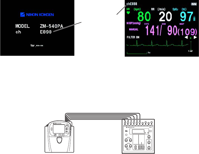
96 Operator’s Manual ZM-540PA/541PA
Channel number
Startup screen Numeric and waveform screen
3. Transmitting/Receiving Signal
Use the AX-400G vital sign simulator and receiving monitor.
1. Connect the vital sign simulator to the transmitter.
AX-400G
2. Place the transmitter 2 to 3 m from the receiving monitor.
3. Set the channel on the receiving monitor to the channel of the transmitter.
4. Turn on the transmitter and vital sign simulator.
5. Check that the ECG of the transmitter appears on the receiving monitor.
6. Turn off the transmitter.
7. Check that the ECG disappears from the receiving monitor.
4. Display
Check that there are no dots missing on the screen.
1. Turn off the transmitter.
2. While pressing the Function key, turn on the transmitter. The MENU screen appears.
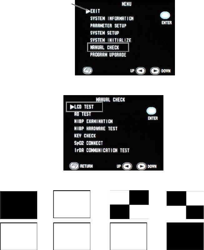
Operator’s Manual ZM-540PA/541PA 97
3. Press the
▼
key to move the cursor to “MANUAL CHECK” and press the Function key.
Cursor
4. Press the
▼
or
▼
key to move the cursor to “LCD TEST” and press the Function key.
5. Each time the
▼
key is pressed, the screen changes as below. Check that no dots are missing.
→ → → →
red → green → blue → → . . .
6. Press the Screen key to return to the MANUAL CHECK screen.
7. Press the Screen key again to return to the MENU screen.
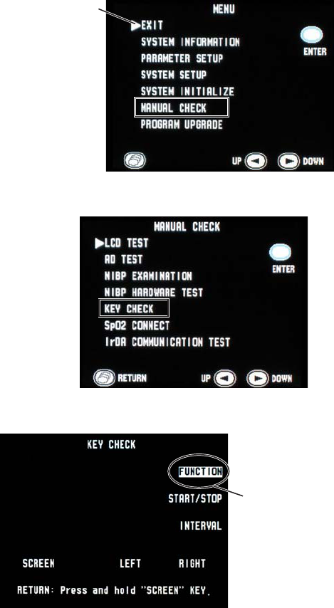
98 Operator’s Manual ZM-540PA/541PA
5. Key Operation
1. Turn off the transmitter.
2. While pressing the Function key, turn on the transmitter. The MENU screen appears.
3. Press the
▼
key to move the cursor to “MANUAL CHECK” and press the Function key.
Cursor
4. Press the
▼
or
▼
key to move the cursor to “KEY CHECK” and press the Function key.
5. Press each key one at a time and check that the pressed key is highlighted on the screen.
Example: when
the Function key is
pressed, the key name
is highlighted
6. After checking, press and hold the Screen key to return to the MANUAL CHECK screen.
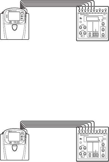
Operator’s Manual ZM-540PA/541PA 99
6. ECG Check
1. Connect the vital sign simulator to the transmitter.
AX-400G
2. Place the transmitter 1 m from the receiving monitor.
3. Turn on the transmitter and vital sign simulator.
4. Check that the ECG of the transmitter appears on the receiving monitor.
7. Respiration Check
1. Connect the vital sign simulator to the transmitter.
AX-400G
2. Place the transmitter 1 m from the receiving monitor.
3. Turn on the transmitter and vital sign simulator.
4. Check that the respiration waveform of the transmitter appears on the receiving monitor.
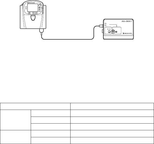
100 Operator’s Manual ZM-540PA/541PA
8. SpO2 Check
1. Connect the SpO2 checker to the transmitter.
AX-300T
2. Place the transmitter 1 m from the receiving monitor.
3. Turn on the transmitter and SpO2 checker.
4. Check that the pulse bar graph appears on the transmitter screen.
5. Check that SpO2 and pulse rate on the transmitter is within the following range.
SpO2 on the SpO2 Checker Range
SpO297% 95 to 99%SpO2 (±2 digit)
80% 78 to 82%SpO2 (±2 digit)
70% 67 to 73%SpO2 (±3 digit)
Pulse rate 60 beats/min 57 to 62 beats/min (±3%/±1 beat/min)
120 beats/min 115 to 124 beats/min (±3%/±1 beat/min)
NOTE
The above range includes the error margin of the SpO2 checker. Therefore, the range is ±1
digit outside the SpO2 measuring accuracy of the transmitter in the “Specifications” section.
6. Check that the SpO2 and pulse waveform of the transmitter appear on the receiving monitor.
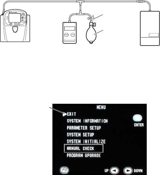
Operator’s Manual ZM-540PA/541PA 101
9. NIBP Check
Check that the transmitter displays the correct cuff pressure and that there is no air leak. The
following procedure uses an electric manometer.
1. Connect the electric manometer and dummy cuff to the transmitter.
NOTE
Air leaks from the rubber ball during inflation. Use a clip on the air hose of the rubber ball to
stop air leaking.
Electric manometer Dummy cuff (700 cc)
Clip
Rubber ball
2. Turn on the electric manometer.
3. While pressing the Function key, turn on the transmitter. The MENU screen appears.
4. Press the
▼
key to move the cursor to “MANUAL CHECK” and press the Function key.
Cursor
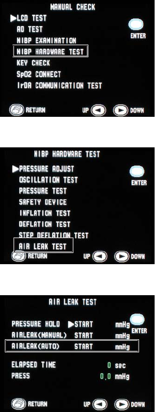
102 Operator’s Manual ZM-540PA/541PA
5. Press the
▼
or
▼
key to move the cursor to “NIBP HARDWARE TEST” and press the
Function key.
6. Press the
▼
or
▼
key to move the cursor to “AIR LEAK TEST” and press the Function key.
7. Press the
▼
or
▼
key to move the cursor to “AIR LEAK (AUTO)” and press the Function key.
The transmitter inflates the cuff up to about 250 mmHg and measures air leakage from 60
seconds to 120 seconds after inflation.
Operator’s Manual ZM-540PA/541PA 103
8. Check the following.
• The value for “AIR LEAK (AUTO)” is below 10 mmHg.
• The difference between the pressure value displayed on the manometer and transmitter is
within ±6 mmHg.
10. NIBP Cuff for Attaching Transmitter to Patient Arm
The NIBP cuff is a consumable. Check the following and when necessary, replace it with a new one.
Appearance
• There are no dirty parts.
• There are no broken stitches on the cuff.
• The label on the cuff is readable.
• The velcro tape on the cuff is not removed and there are no broken stitches.
• The lock plate is not damaged and functions properly.
Inflation bag
• The inflation bag is not torn or damaged.
• There is no water inside the inflation bag.
• The connector on the inflation bag is not damaged.

104 Operator’s Manual ZM-540PA/541PA
Maintenance Check Sheet
Hospital/Organization:
Service Personnel:
Instrument Name: Transmitter
Instrument Model: ZM-540PA/ZM-541PA
Instrument Serial Number:
Hardware Revision Number:
Software Revision Number:
1. External Check OK No
2. Transmitter Channel OK No
3. Transmitting/Receiving Signal OK No
4. Display OK No
5. Key Operation OK No
6. ECG Check OK No
7. Respiration Check OK No
8. SpO2 Check OK No
9. NIBP Check OK No
10. NIBP Cuff for Attaching Transmitter to Patient Arm OK No
Overall Judgement
□ OK
□ Can be used but needs maintenance
□ Maintenance required. Cannot be used.

Operator’s Manual ZM-540PA/541PA 105
Lifetime and Disposal
CAUTION
Dispose of the transmitter, options and accessories as specified by Nihon Kohden.
Otherwise, it causes infection or environmental contamination.
Disposing of Used Batteries
Battery Lifetime
Replace the batteries when the battery replacement indication appears on the transmitter. When
using rechargeable batteries, recharge them.
Disposal
NOTE
Remove the batteries before disposing of the transmitter.
Before disposing of the batteries, check with your local solid waste officials for details in your area
for proper disposal. It may be illegal to dispose of these batteries in the municipal waste stream.
Disposing of Electrodes, SpO2 Probes and NIBP Cuffs
Refer to the manual for each item.
Disposing of Transmitter
Remove the batteries from the transmitter and dispose of the transmitter following your local laws
for disposal.

106 Operator’s Manual ZM-540PA/541PA
Cleaning, Disinfection and Sterilization
Transmitter and Electrode Leads
CAUTION
This transmitter is not waterproof. If detergent or liquid spills into the transmitter, stop
cleaning or disinfecting it and contact your Nihon Kohden representative. The
transmitter needs to be checked for safety and function before use.
NOTE
The transmitter cannot be sterilized. Sterilizing the transmitter may damage it.
Before cleaning or disinfecting, remove the batteries from the transmitter. Be careful not to let any
liquid get inside the transmitter.
Cleaning
Wipe the transmitter and electrode leads with a soft cloth moistened with disinfecting alcohol or
neutral detergent diluted with water. After cleaning, dry them completely.
Use cotton swab moistened with neutral detergent diluted with water to clean inside the battery
compartment.
Disinfection
CAUTION
Do not immerse the electrode lead connector in liquid.
Wipe the outside surface of the transmitter and electrode lead with a non-abrasive cloth moistened
with any of the disinfectants listed below. For details on the disinfectants, refer to the instruction
provided with the disinfectants. Use the recommended concentration.
Disinfectant Concentration (%)
Glutaraldehyde solution 2.0
Alkyldiaminoethylglycine hydrochloride 0.5
Benzalkonium chloride 0.2
Benzethonium chloride solution 0.2
Chlorhexidine gluconate solution 0.5

Operator’s Manual ZM-540PA/541PA 107
SpO2 Probe
Refer to the probe manual.
YP-503P/YP-504P NIBP Cuffs
NOTE
• Do not autoclave the cuff.
• Use only glutaraldehyde solution.
• Never allow liquid to get inside the inflation bag.
• Do not sterilize or disinfect the cuff with ultraviolet light or ozone.
Cleaning
To clean the cuff, remove the lock plate and carefully pull out the inflation bag from the cloth cover.
Cloth cover: Wash with neutral detergent and water. Thoroughly dry it. When washing in a washing
machine, put it in a net.
Inflation bag:
Wipe with a soft cloth or cotton moistened with isopropyl alcohol. Thoroughly dry it.
Disinfection
To disinfect the cuff, use glutaraldehyde solution. Use the recommended concentration of the
disinfectant. Refer to the disinfectant manual for details. After disinfection, clean the cuff as
described above.
Repair Parts Availability Policy
Nihon Kohden Corporation (NKC) shall stock repair parts (parts necessary to maintain the
performance of the instrument) for a period of 8 years from the date of delivery. In that period NKC
or its authorized agents will repair the instrument. This period may be shorter than 8 years if a board
or part necessary for the faulty section is not available.

108 Operator’s Manual ZM-540PA/541PA
Specifications
ZM-540PA
Measuring Parameters
Measuring waveforms: ECG, respiration in impedance method, pulse
Measuring numeric data: Heart rate, respiration rate, SpO2, NIBP, pulse rate
Transmitting Data
Waveform data: ECG, respiration, pulse wave
Numeric data: SpO2, NIBP, pulse rate
Status information: Battery replacement, battery level*, alarm suspended,
pause monitoring*, patient confirmed*, ECG lead, pacing
detection, electrode detachment, electrode impedance*,
ECG off*, respiration method (impedance)*, SpO2 status,
NIBP status, channel ID, time constant (3.2 s), type of
transmitter, transmitter code number*, transmitter serial
number*
* The items marked with * are transmitted only when the protocol is “57”.
Display
Display size: 2.2 inch TFT color LCD
Viewing area: 44.16 (H) × 33.12 (V) mm
Resolution: 320 (H) × 240 (V) dots
Displayed Data
Numeric and waveform screen: ECG (one waveform from lead I, II, III, Va or Vb), heart
rate, pulse rate, respiration rate, SpO2, NIBP (systolic,
diastolic, MAP), message, battery level, QRS/pulse sync
mark, pulse bar graph, NIBP measurement mode and status
information, ECG lead
Waveform review screen: ECG or pulse wave of past 10 minutes
Numeric review screen: Heart rate or pulse rate, respiration rate and SpO2 at 1
minute interval for past 10 minutes
Check electrodes screen: ECG for checking electrode attachment
ECG
ECG measurement
Channels: 4
Operator’s Manual ZM-540PA/541PA 109
Input dynamic range: ±10 mV or more
Electrode offset potential tolerance: ±500 mV or more
Input impedance: 5 MΩ or more
Common mode rejection ratio: 95 dB or more
IEC 60601-2-27 50.102.10 complied
Pacing pulse detection: amplitude ±2 to 700 mV, duration 0.1 to 2 ms
IEC 60601-2-27: 2005 complied
Based upon pacemaker pulse rejection capability
Defibrillation-proof: ECG input protected against 400 Ws/DC 5 kV
IEC 60601-2-27 17.101 complied
ECG recovery time after defibrillation: within 10 s
Electrode condition: Displays CHECK ELECTRODES message
Tall T-wave rejection capability: Complies with the heights of T-waves from 0 to 1.6 mV
IEC 60601-2-27: 2005 50.102.17 complied
Pacemaker pulse rejection capability, without overshoot:
Complies with the amplitudes of pacemaker pulses ±2 to
±700 mV and widths 0.1 to 2 ms (As defined by method B
of IEC 60601-2-27: 2005 50.102.13, this corresponds to the
pacemaker pulses amplitudes and widths of ±2.8 mV/2 ms
to amplitudes ±45.6 mV/0.1 ms.)
Pacemaker pulse rejection capability, with overshoot:
Overshoot amplitudes and time constants of ±0.12
mV/100 ms to ±2 mV/4 ms (As defined by method B of
IEC 60601-2-27: 2005 50.102.13, this corresponds to the
pacemaker pulses amplitudes and widths of ±2.8 mV/2 ms
to amplitudes ±45.6 mV/0.1 ms.)
ECG display and heart rate count
Frequency characteristic: filter on: 1 to 18 Hz, filter off: 0.05 to 60 Hz
Heart rate detection method: Average
QRS detection: 70 to 120 ms: amplitude ≥ 0.5 mV, rate 30 to 200 beats/min
40 to 120 ms: amplitude ≥ 0.5 mV, rate 30 to 250 beats/min
Heart rate counting range: 0, 15 to 300 beats/min
Heart rate counting accuracy*: ±2 beats/min, (0, 15 to 300 beats/min)
* Essential performance of this transmitter
Respiration Measurement
Measuring method: Impedance method
Measuring lead: Between R and F
Impedance range: 2 kΩ or less
Respiration rate measuring accuracy*: ±2 counts/min (at 0 to 150 counts/min)
Respiration rate counting range: 0 to 150 counts/min
* Essential performance of this transmitter
110 Operator’s Manual ZM-540PA/541PA
SpO2 Measurement (ISO 9919: 2005 complied)
Measuring range: 0 to 100%SpO2
Declared range: 70 to 100%SpO2
Minimum display range: 1%SpO2
Display update cycle: Every 3 seconds
Measuring accuracy (rms)*: Accuracy assurance temperature: 18 to 40ºC
Total accuracy including probe: 80%SpO2 ≤ %SpO2 ≤ 100%SpO2: ±2%SpO2
70%SpO2 ≤ %SpO2 < 80%SpO2: ±3%SpO2
under 70%SpO2: not specified
Accuracy of the transmitter: 80%SpO2 ≤ %SpO2 ≤ 100%SpO2: ±1%SpO2
50%SpO2 ≤ %SpO2 < 80%SpO2: ±2%SpO2
under 50%SpO2: not specified
Pulse rate measuring range: 30 to 300 bpm
Pulse rate display range: 30 to 300 bpm
Pulse rate accuracy (rms)*: ±3% ±1 bpm
* Essential performance of this transmitter
NOTE
• The SpO2 measuring accuracy was tested using the TL-201T, TL-260T, TL-271T and
TL-631T SpO2 probes. The testing was performed during induced hypoxia on healthy
volunteers (Ethnicity: 10 Caucasians, 2 Africans, 1 Asian and 3 Indians), (Skin: 8 light,
4 medium, 4 dark), (Age: 21 to 34), (5 women and 11 men) under the condition of no
motion. Arterial blood was sampled and measured by a CO-oximeter. The difference
between SpO2 measured by the SpO2 probe and functional SaO2 measured by a CO-
oximeter was calculated using the root-mean-square (rms) method according to ISO
9919: 2005. This measurement accuracy figure represents 2/3 of all test measurements.
• A pulse oximeter tester that generates simulated signals can be used to check the
difference from the design specification, but it cannot be used as a replacement for
human signals for testings accuracy.
Response time:
Selectable from “Slow”, “Normal” and “Fast”.
The following graphs show the response time example when SpO2 changes 0.6%/s.
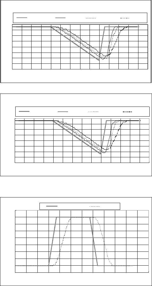
Operator’s Manual ZM-540PA/541PA 111
Pulse Rate = 70 bpm
60
65
70
75
80
85
90
95
100
0 10 20 30 40 50 60 70 80 90 100 110 120 130 140
Time (seconds)
SpO2 (%)
SpO
2
Reference SpO
2
Fast SpO
2
Normal SpO
2
Slow
60
65
70
75
80
85
90
95
100
0 10 20 30 40 50 60 70 80 90 100 110 120 130 140
SpO
2
Reference SpO
2
Fast SpO
2
Normal
Pulse Rate = 140 bpm
Time (seconds)
SpO
2
(%)
SpO
2
Slow
The following graph shows the response time example when pulse rate changes 10 bpm/s.
SpO
2
= 97
60
70
80
90
100
110
120
130
140
150
0 102030405060708090100110120
Time (seconds)
PR (bpm)
PR Reference
PR
112 Operator’s Manual ZM-540PA/541PA
Non Invasive Blood Pressure, NIBP (IEC 60601-2-30: 1999 complied)
Measuring method: Oscillometric
Measurement mode: Manual, STAT (≤ 15 min), Periodic
Intended patient type: Adult, child
Measuring range: 0 to 300 mmHg
Pressure display range: 0 to 300 mmHg
Measuring accuracy*: ±3 mmHg (0 mmHg ≤ NIBP ≤ 300 mmHg)
AAMI SP-10: 2002 complied
Cuff inflation time: ≤ 20 s (700 cc), 0 to 200 mmHg
≤ 15 s (70 cc), 0 to 200 mmHg
Pressure retention: ≤ 5 mmHg (250 cc at 250 mmHg inflation for 10 seconds)
Air leakage: ≤ 3 mmHg/min (700 cc at 300 mmHg inflation)
Power discontinuity: Deflate immediately after power down
Safety
Maximum pressurization value cuff inflation limiter: 300 to 330 mmHg
Cuff inflation time limiter: ≤ 180 s
Interval time limiter: ≤ 30 s
* Essential performance of this transmitter
Transmitter
FCC regulation: FCC part 95 Subpart H
Wireless Medical Telemetry Service (WMTS)
Field strength limits: < 200 mV/m (at 3 m)
Undesired emissions: below 960 MHz: < 200 μV/m (at 3 m)
above 960 MHz: < 500 μV/m (at 3 m)
Antenna: Internal
Transmission channel: Indicated on the transmitter
Transmission frequency range: 608.0250 to 613.9750 MHz
Channel spacing: 50 kHz or 37.5 kHz (12.5 kHz when interleaved)
Modulation: FSK (frequency shift keying)
Type of emission: F1D
Occupied bandwidth: < 20 kHz
Effective radiated power: 1.0 mW
Power Requirements
Rated voltage: 3.6 V
Operating voltage: 3.2 to 4.8 V
Battery type: Three AA (R6) type NiMH secondary batteries
Three AA (R6) type alkaline dry cell primary batteries
Battery lifetime (with alkaline batteries, at room temperature):
approximately 1 day
(measuring ECG, respiration, SpO2 of approximately 60 kg
weight adult male patient at the index finger, NIBP at 60
minute intervals)
Operator’s Manual ZM-540PA/541PA 113
Dimension and Weight
Dimension: 114 W × 125 H × 63 D (mm)
Weight: about 340 g (excluding batteries and other accessories)
about 410 g (including batteries, excluding other
accessories)
Environment
Operating environment
Temperature: 5 to 40°C, 41 to 104°F
Humidity: 30 to 85% (noncondensing)
Atmospheric pressure: 700 to 1060 hPa
Storage and transport environment
Temperature: −20 to +65°C, −4 to +149°F
Humidity: 10 to 95%
Atmospheric pressure: 700 to 1060 hPa
Safety Standards
Safety standard: CAN/CSA-C22.2 No. 601-1 M90
CAN/CSA-C22.2 No. 601-1. 1S1-94
CAN/CSA-C22.2 No. 601-1. 1B-90
CAN/CSA-C22.2 No. 60601-2-49-04
CAN/CSA-C22.2 No. 60601-2-27-06
CAN/CSA-C22.2 No. 60601-2-30-02
IEC 60601-1:1988
IEC 60601-1 Amendment 1: 1991
IEC 60601-1 Amendment 2: 1995
IEC 60601-2-27: 2005
IEC 60601-2-30: 1999
IEC 60601-2-49: 2001
ISO 9919: 2005
Type of protection against electrical shock: INTERNALLY POWERED EQUIPMENT
Degree of protection against electrical shock:
ECG and impedance method respiration: DEFIBRILLATION-PROOF TYPE CF APPLIED
PART
SpO2 and NIBP: DEFIBRILLATION-PROOF TYPE BF APPLIED
PART
Degree of protection against harmful ingress of water: IPX0 (Ordinary equipment)
Degree of safety of application in the presence of a FLAMMABLE ANAESTHETIC MIXTURE
WITH AIR, OR WITH OXYGEN OR NITROUS OXIDE:
Equipment not suitable for use in the presence of
FLAMMABLE ANAESTHETIC MIXTURE WITH
AIR, OR WITH OXYGEN OR NITROUS OXIDE

114 Operator’s Manual ZM-540PA/541PA
Mode of operation: CONTINUOUS OPERATION
Electromagnetic Compatibility
IEC 60601-1-2: 2001
IEC 60601-1-2 Amendment 1: 2004
Electromagnetic Emissions
This Model ZM-540PA is intended for use in the electromagnetic environment specified below.
The customer or the user of the ZM-540PA should assure that it is used in such an environment.
Emissions test Compliance Electromagnetic environment - guidance
RF emissions
CISPR 11
Group 1 The ZM-540PA uses RF energy only for its internal
function. Therefore, its RF emissions are very
low and are not likely to cause any interference in
nearby electronic equipment.
RF emissions
CISPR 11
Class B The ZM-540PA is suitable for use in all
establishments, including domestic establishments.
Harmonic emissions
IEC 61000-3-2
Not applicable
Voltage fluctuations/
flicker emissions
IEC 61000-3-3
Not applicable

Operator’s Manual ZM-540PA/541PA 115
Electromagnetic Immunity
This Model ZM-540PA is intended for use in the electromagnetic environment specified below.
The customer or the user of the ZM-540PA should assure that it is used in such an environment.
Immunity test IEC 60601 test
level
Compliance
level
Electromagnetic
environment - guidance
Electrostatic
discharge (ESD)
IEC 61000-4-2
±6 kV contact
±8 kV air
±6 kV contact
±8 kV air
Floors should be wood, concrete
or ceramic tile. If floors are
covered with synthetic material,
the relative humidity should be at
least 30%.
Electrical fast
transient/ burst
IEC 61000-4-4
±2 kV for power
supply lines
±1 kV for input/output
lines
Not applicable
—
Surge
IEC 61000-4-5
±1 kV differential
mode
±2 kV common mode
Not applicable
—
Voltage dips, short
interruptions and
voltage variations
on power supply
input lines
IEC 61000-4-11
<5% UT (>95% dip in
UT) for 0.5 cycle
40% UT (60% dip in
UT) for 5 cycles
70% UT (30% dip in
UT) for 25 cycles
<5% UT (>95% dip in
UT) for 5 s
Not applicable
—
Power frequency
(50/60 Hz)
magnetic field
IEC 61000-4-8
3 A/m 3 A/m Power frequency magnetic fields
should be at levels characteristic
of a typical location in a
typical commercial or hospital
environment.
NOTE: UT is the AC mains voltage prior to application of the test level
Avoiding Electromagnetic Interference (Impedance Respiration)
Impedance respiration measurement is very sensitive and affected by electromagnetic interference.
Technological limitations do not allow immunity levels higher than 1 V/m for radiated RF
electromagnetic fields. Electromagnetic fields with field strengths above 1 V/m may cause
measurement error. Do not use electrically radiating equipment near the impedance respiration
measurements.

116 Operator’s Manual ZM-540PA/541PA
Immunity test IEC 60601 test
level
Compliance
level
Electromagnetic environment
- guidance
Conducted RF
IEC 61000-4-6
Radiated RF
IEC 61000-4-3
3 Vrms
150 kHz to 80 MHz
3 V/m
80 MHz to 2.5 GHz
3 Vrms
3 V/m 80 MHz to
2.5 GHz
(1 V/m 80 MHz
to 2.5 GHz for
respiration)
Portable and mobile RF communications
equipment should be used no closer to any
part of the ZM-540PA, including cables,
than the recommended separation distance
calculated from the equation applicable to
the frequency of the transmitter.
Recommended separation distance
d = 1.2㺕P
d = 1.2㺕P 80 MHz to 800 MHz
d = 2.3㺕P 800 MHz to 2.5 GHz
(d = 3.5㺕P 80 MHz to 800 MHz for
respiration
d = 7.0㺕P 800 MHz to 2.5 GHz for
respiration)
where P is the maximum output power
rating of the transmitter in watts (W)
according to the transmitter manufacturer
and d is the recommended separation
distance in meters (m).
Field strengths from fixed RF transmitters,
as deter mined by an electromagnetic
site survey*1, should be less than the
compliance level in each frequency
range*2.
Interference may occur in the vicinity of
equipment marked with the following
symbol:
NOTE 1: At 80 MHz and 800 MHz, the higher frequency range applies.
NOTE 2: These guidelines may not apply in all situations. Electromagnetic propagation is affected by
absorption and reflection from structures, objects and people.
*1 Field strengths from fixed transmitters, such as base stations for radio (cellular/cordless) telephones and
land mobile radios, amateur radio, AM and FM radio broadcast and TV broadcast cannot be predicted
theoretically with accuracy. To assess the electromagnetic environment due to fixed RF transmitters, an
electromagnetic site survey should be considered. If the measured field strength in the location in which
the ZM-540PA is used exceeds the applicable RF compliance level above, the ZM-540PA should be
observed to verify normal operation. If abnormal performance is observed, additional measures may be
necessary, such as re-orienting or relocating the ZM-540PA.
*2 Over the frequency range 150 kHz to 80 MHz, field strengths should be less than 1 V/m for respiration
and 3 V/m for all other functions.

Operator’s Manual ZM-540PA/541PA 117
Recommended Separation Distances between Portable and Mobile RF
Communications Equipment
The ZM-540PA is intended for use in an electromagnetic environment in which radiated RF
disturbances are controlled. The customer or the user of the ZM-540PA can help prevent
electromagnetic interference by maintaining a minimum distance between portable and mobile RF
communications equipment (transmitters) and the ZM-540PA as recommended below, according to
the maximum output power of the communications equipment.
Rated maximum output
power of transmitter
(W)
Separation distance according to frequency of transmitter (m)
150 kHz to 80 MHz
d = 1.2㺕P
80 MHz to 800 MHz
d = 1.2㺕P
(For respiration:
d = 3.5㺕P)
800 MHz to 2.5 GHz
d = 2.3㺕P
(For respiration:
d = 7.0㺕P)
0.01 0.12 0.12 (0.35*) 0.23 (0.7*)
0.1 0.38 0.38 (1.1*) 0.73 (2.2*)
1 1.2 1.2 (3.5*) 2.3 (7.0*)
10 3.8 3.8 (11*) 7.3 (22*)
100 12 12 (35*) 23 (70*)
For transmitters rated at a maximum output power not listed above, the recommended separation
distance d in meters (m) can be estimated using the equation applicable to the frequency of the
transmitter, where P is the maximum output power rating of the transmitter in watts (W) according
to the transmitter manufacturer.
(* For respiration)
NOTE 1 At 80 MHz and 800 MHz, the separation distance for the higher frequency range applies.
NOTE 2 These guidelines may not apply in all situations. Electromagnetic propagation is affected
by absorption and reflection from structures, objects and people.
Recovery Time after Defibrillation
The transmitter returns to the normal operating mode within 10 seconds after defibrillation. The
stored settings are not affected.
System Composition for EMC Test
The ZM-540PA bedside monitor is tested to comply with IEC 60601-1-2: 2001 with the following
composition.
Units Cable length
ZM-540PA transmitter —
YP-503P NIBP cuff 0.15 m
BR-906P ECG electrode lead 0.8 m
TL-201T finger probe 1.6 m
118 Operator’s Manual ZM-540PA/541PA
ZM-541PA
Measuring Parameters
Measuring waveforms: ECG, respiration in impedance method, pulse
Measuring numeric data: Heart rate, respiration rate, SpO2, NIBP, pulse rate
Transmitting Data
Waveform data: ECG, respiration, pulse wave
Numeric data: SpO2, NIBP, pulse rate
Status information: Battery replacement, battery level*, alarm suspended,
pause monitoring*, patient confirmed*, ECG lead, pacing
detection, electrode detachment, electrode impedance*,
ECG off*, respiration method (impedance)*, SpO2 status,
NIBP status, channel ID, time constant (3.2 s), type of
transmitter, transmitter code number*, transmitter serial
number*
* The items marked with * are transmitted only when the protocol is “57”.
Display
Display size: 2.2 inch TFT color LCD
Viewing area: 44.16 (H) × 33.12 (V) mm
Resolution: 320 (H) × 240 (V) dots
Displayed Data
Numeric and waveform screen: ECG (one waveform from lead I, II, III, Va or Vb), heart
rate, pulse rate, respiration rate, SpO2, NIBP (systolic,
diastolic, MAP), message, battery level, QRS/pulse sync
mark, pulse bar graph, NIBP measurement mode and status
information, ECG lead
Waveform review screen: ECG or pulse wave of past 10 minutes
Numeric review screen: Heart rate or pulse rate, respiration rate and SpO2 at 1
minute interval for past 10 minutes
CHECK ELECTRODE screen: ECG for checking electrode attachment
ECG
ECG measurement
Channels: 4
Input dynamic range: ±10 mV or more
Electrode offset potential tolerance: ±500 mV or more
Input impedance: 5 MΩ or more
Common mode rejection ratio: 95 dB or more
IEC 60601-2-27 50.102.10 complied
Operator’s Manual ZM-540PA/541PA 119
Pacing pulse detection: amplitude ±2 to 700 mV, duration 0.1 to 2 ms
IEC 60601-2-27: 2005 complied
Based upon pacemaker pulse rejection capability
Defibrillation-proof: ECG input protected against 400 Ws/DC 5 kV
IEC 60601-2-27 17.101 complied
ECG recovery time after defibrillation: within 10 s
Electrode condition: Displays CHECK ELECTRODES message
Tall T-wave rejection capability: Complies with the heights of T-waves from 0 to 1.6 mV
IEC 60601-2-27: 2005 50.102.17 complied
Pacemaker pulse rejection capability, without overshoot:
Complies with the amplitudes of pacemaker pulses ±2 to
±700 mV and widths 0.1 to 2 ms (As defined by method B
of IEC 60601-2-27: 2005 50.102.13, this corresponds to the
pacemaker pulses amplitudes and widths of ±2.8 mV/2 ms
to amplitudes ±45.6 mV/0.1 ms.)
Pacemaker pulse rejection capability, with overshoot:
Overshoot amplitudes and time constants of ±0.12
mV/100 ms to ±2 mV/4 ms (As defined by method B of
IEC 60601-2-27: 2005 50.102.13, this corresponds to the
pacemaker pulses amplitudes and widths of ±2.8 mV/2 ms
to amplitudes ±45.6 mV/0.1 ms.)
ECG display and heart rate count
Frequency characteristic: filter on: 1 to 18 Hz, filter off: 0.05 to 60 Hz
Heart rate detection method: Average
QRS detection: 70 to 120 ms: amplitude ≥ 0.5 mV, rate 30 to 200 beats/min
40 to 120 ms: amplitude ≥ 0.5 mV, rate 30 to 250 beats/min
Heart rate counting range: 0, 15 to 300 beats/min
Heart rate counting accuracy*: ±2 beats/min, (0, 15 to 300 beats/min)
* Essential performance of this transmitter
Respiration Measurement
Measuring method: Impedance method
Measuring lead: Between R and F
Impedance range: 2 kΩ or less
Respiration rate measuring accuracy*: ±2 counts/min (at 0 to 150 counts/min)
Respiration rate counting range: 0 to 150 counts/min
* Essential performance of this transmitter
SpO2 Measurement (ISO 9919: 2005 complied)
Measuring range: 0 to 100%SpO2
Declared range: 70 to 100%SpO2
Minimum display range: 1%SpO2
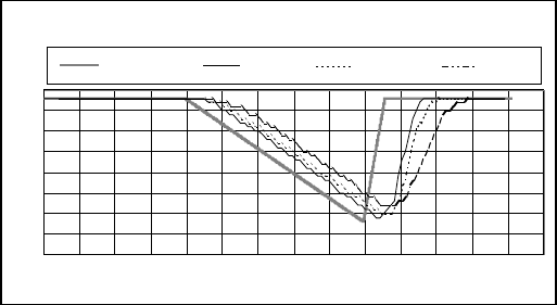
120 Operator’s Manual ZM-540PA/541PA
Display update cycle: Every 3 seconds
Measuring accuracy (rms)*: Accuracy assurance temperature: 18 to 40ºC
Total accuracy including probe: 80%SpO2 ≤ %SpO2 ≤ 100%SpO2: ±2%SpO2
70%SpO2 ≤ %SpO2 < 80%SpO2: ±3%SpO2
under 70%SpO2: not specified
Accuracy of the transmitter: 80%SpO2 ≤ %SpO2 ≤ 100%SpO2: ±1%SpO2
50%SpO2 ≤ %SpO2 < 80%SpO2: ±2%SpO2
under 50%SpO2: not specified
Pulse rate measuring range: 30 to 300 bpm
Pulse rate display range: 30 to 300 bpm
Pulse rate accuracy (rms)*: ±3% ±1 bpm
* Essential performance of this transmitter
NOTE
• The SpO2 measuring accuracy was tested using the TL-201T, TL-260T, TL-271T and
TL-631T SpO2 probes. The testing was performed during induced hypoxia on healthy
volunteers (Ethnicity: 10 Caucasians, 2 Africans, 1 Asian and 3 Indians), (Skin: 8 light,
4 medium, 4 dark), (Age: 21 to 34), (5 women and 11 men) under the condition of no
motion. Arterial blood was sampled and measured by a CO-oximeter. The difference
between SpO2 measured by the SpO2 probe and functional SaO2 measured by a CO-
oximeter was calculated using the root-mean-square (rms) method according to ISO
9919: 2005. This measurement accuracy figure represents 2/3 of all test measurements.
• A pulse oximeter tester that generates simulated signals can be used to check the
difference from the design specification, but it cannot be used as a replacement for
human signals for testings accuracy.
Response time:
Selectable from “Slow”, “Normal” and “Fast”.
The following graphs show the response time example when SpO2 changes 0.6%/s.
Pulse Rate = 70 bpm
60
65
70
75
80
85
90
95
100
0 10 20 30 40 50 60 70 80 90 100 110 120 130 140
Time (seconds)
SpO2 (%)
SpO
2
Reference SpO
2
Fast SpO
2
Normal SpO
2
Slow
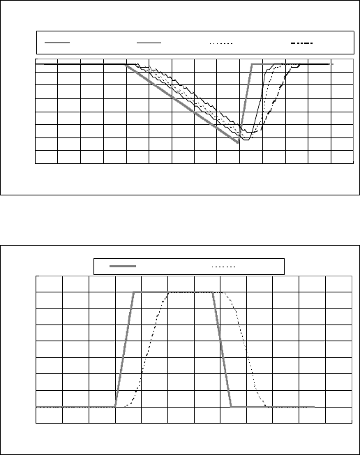
Operator’s Manual ZM-540PA/541PA 121
60
65
70
75
80
85
90
95
100
0 10 20 30 40 50 60 70 80 90 100 110 120 130 140
SpO
2
Reference SpO
2
Fast SpO
2
Normal
Pulse Rate = 140 bpm
Time (seconds)
SpO
2
(%)
SpO
2
Slow
The following graph shows the response time example when pulse rate changes 10 bpm/s.
SpO
2
= 97
60
70
80
90
100
110
120
130
140
150
0 102030405060708090100110120
Time (seconds)
PR (bpm)
PR Reference
PR
Non Invasive Blood Pressure, NIBP (IEC 60601-2-30: 1999 complied)
Measuring method: Oscillometric
Measurement mode: Manual, STAT (≤ 15 min), Periodic
Intended patient type: Adult, child
Measuring range: 0 to 300 mmHg
Pressure display range: 0 to 300 mmHg
Measuring accuracy*: ±3 mmHg (0 mmHg ≤ NIBP ≤ 300 mmHg)
AAMI SP-10: 2002 complied
Cuff inflation time: ≤ 20 s (700 cc), 0 to 200 mmHg
≤ 15 s (70 cc), 0 to 200 mmHg
Pressure retention: ≤ 5 mmHg (250 cc at 250 mmHg inflation for 10 seconds)
Air leakage: ≤ 3 mmHg/min (700 cc at 300 mmHg inflation)
Power discontinuity: Deflate immediately after power down
122 Operator’s Manual ZM-540PA/541PA
Safety
Maximum pressurization value cuff inflation limiter: 300 to 330 mmHg
Cuff inflation time limiter: ≤ 180 s
Interval time limiter: ≤ 30 s
* Essential performance of this transmitter
Transmitter
FCC regulation: FCC part 95 Subpart H
Wireless Medical Telemetry Service (WMTS)
Field strength limits: < 740 mV/m (at 3 m)
Undesired emissions: below 960 MHz: < 200 μV/m (at 3 m)
above 960 MHz: < 500 μV/m (at 3 m)
Antenna: Internal
Transmission channel: Indicated on the transmitter
Transmission frequency range: 1395.0250 to 1399.9750 MHz
1427.0250 to 1431.9750 MHz
Channel spacing: 50 kHz or 37.5 kHz (12.5 kHz when interleaved)
Modulation: FSK (frequency shift keying)
Type of emission: F1D
Occupied bandwidth: < 20 kHz
Effective radiated power: 5.0 mW
Can be changed to 1.0 mW if required
Power Requirements
Rated voltage: 3.6 V
Operating voltage: 3.2 to 4.8 V
Battery type: Three AA (R6) type NiMH secondary batteries
Three AA (R6) type alkaline dry cell primary batteries
Battery lifetime (with alkaline batteries, at room temperature):
approximately 1 day
(measuring ECG, respiration, SpO2 of approximately 60 kg
weight adult male patient at the index finger, NIBP at 60
minute intervals)
Dimension and Weight
Dimension: 114 W × 125 H × 63 D (mm)
Weight: about 340 g (excluding batteries and other accessories)
about 410 g (including batteries, excluding other
accessories)
Operator’s Manual ZM-540PA/541PA 123
Environment
Operating environment
Temperature: 5 to 40°C, 41 to 104°F
Humidity: 30 to 85% (noncondensing)
Atmospheric pressure: 700 to 1060 hPa
Storage and transport environment
Temperature: −20 to +65°C, −4 to +149°F
Humidity: 10 to 95%
Atmospheric pressure: 700 to 1060 hPa
Safety Standards
Safety standard: CAN/CSA-C22.2 No. 601-1 M90
CAN/CSA-C22.2 No. 601-1. 1S1-94
CAN/CSA-C22.2 No. 601-1. 1B-90
CAN/CSA-C22.2 No. 60601-2-49-04
CAN/CSA-C22.2 No. 60601-2-27-06
CAN/CSA-C22.2 No. 60601-2-30-02
IEC 60601-1:1988
IEC 60601-1 Amendment 1: 1991
IEC 60601-1 Amendment 2: 1995
IEC 60601-2-27: 2005
IEC 60601-2-30: 1999
IEC 60601-2-49: 2001
ISO 9919: 2005
Type of protection against electrical shock: INTERNALLY POWERED EQUIPMENT
Degree of protection against electrical shock:
ECG and impedance method respiration: DEFIBRILLATION-PROOF TYPE CF APPLIED
PART
SpO2 and NIBP: DEFIBRILLATION-PROOF TYPE BF APPLIED
PART
Degree of protection against harmful ingress of water: IPX0 (Ordinary equipment)
Degree of safety of application in the presence of a FLAMMABLE ANAESTHETIC MIXTURE
WITH AIR, OR WITH OXYGEN OR NITROUS OXIDE:
Equipment not suitable for use in the presence of
FLAMMABLE ANAESTHETIC MIXTURE WITH
AIR, OR WITH OXYGEN OR NITROUS OXIDE
Mode of operation: CONTINUOUS OPERATION
Electromagnetic Compatibility
IEC 60601-1-2: 2001
IEC 60601-1-2 Amendment 1: 2004

124 Operator’s Manual ZM-540PA/541PA
Electromagnetic Emissions
This Model ZM-541PA is intended for use in the electromagnetic environment specified below.
The customer or the user of the ZM-541PA should assure that it is used in such an environment.
Emissions test Compliance Electromagnetic environment - guidance
RF emissions
CISPR 11
Group 1 The ZM-541PA uses RF energy only for its internal
function. Therefore, its RF emissions are very
low and are not likely to cause any interference in
nearby electronic equipment.
RF emissions
CISPR 11
Class B The ZM-541PA is suitable for use in all
establishments, including domestic establishments.
Harmonic emissions
IEC 61000-3-2
Not applicable
Voltage fluctuations/
flicker emissions
IEC 61000-3-3
Not applicable

Operator’s Manual ZM-540PA/541PA 125
Electromagnetic Immunity
This Model ZM-541PA is intended for use in the electromagnetic environment specified below.
The customer or the user of the ZM-541PA should assure that it is used in such an environment.
Immunity test IEC 60601 test
level
Compliance
level
Electromagnetic
environment - guidance
Electrostatic
discharge (ESD)
IEC 61000-4-2
±6 kV contact
±8 kV air
±6 kV contact
±8 kV air
Floors should be wood, concrete
or ceramic tile. If floors are
covered with synthetic material,
the relative humidity should be at
least 30%.
Electrical fast
transient/ burst
IEC 61000-4-4
±2 kV for power
supply lines
±1 kV for input/output
lines
Not applicable
—
Surge
IEC 61000-4-5
±1 kV differential
mode
±2 kV common mode
Not applicable
—
Voltage dips, short
interruptions and
voltage variations
on power supply
input lines
IEC 61000-4-11
<5% UT (>95% dip in
UT) for 0.5 cycle
40% UT (60% dip in
UT) for 5 cycles
70% UT (30% dip in
UT) for 25 cycles
<5% UT (>95% dip in
UT) for 5 s
Not applicable
—
Power frequency
(50/60 Hz)
magnetic field
IEC 61000-4-8
3 A/m 3 A/m Power frequency magnetic fields
should be at levels characteristic
of a typical location in a
typical commercial or hospital
environment.
NOTE: UT is the AC mains voltage prior to application of the test level
Avoiding Electromagnetic Interference (Impedance Respiration)
Impedance respiration measurement is very sensitive and affected by electromagnetic interference.
Technological limitations do not allow immunity levels higher than 1 V/m for radiated RF
electromagnetic fields. Electromagnetic fields with field strengths above 1 V/m may cause
measurement error. Do not use electrically radiating equipment near the impedance respiration
measurements.

126 Operator’s Manual ZM-540PA/541PA
Immunity test IEC 60601 test
level
Compliance
level
Electromagnetic environment
- guidance
Conducted RF
IEC 61000-4-6
Radiated RF
IEC 61000-4-3
3 Vrms
150 kHz to 80 MHz
3 V/m
80 MHz to 2.5 GHz
3 Vrms
3 V/m 80 MHz to
2.5 GHz
(1 V/m 80 MHz
to 2.5 GHz for
respiration)
Portable and mobile RF communications
equipment should be used no closer to any
part of the ZM-541PA, including cables,
than the recommended separation distance
calculated from the equation applicable to
the frequency of the transmitter.
Recommended separation distance
d = 1.2㺕P
d = 1.2㺕P 80 MHz to 800 MHz
d = 2.3㺕P 800 MHz to 2.5 GHz
(d = 3.5㺕P 80 MHz to 800 MHz for
respiration
d = 7.0㺕P 800 MHz to 2.5 GHz for
respiration)
where P is the maximum output power
rating of the transmitter in watts (W)
according to the transmitter manufacturer
and d is the recommended separation
distance in meters (m).
Field strengths from fixed RF transmitters,
as deter mined by an electromagnetic
site survey*1, should be less than the
compliance level in each frequency
range*2.
Interference may occur in the vicinity of
equipment marked with the following
symbol:
NOTE 1: At 80 MHz and 800 MHz, the higher frequency range applies.
NOTE 2: These guidelines may not apply in all situations. Electromagnetic propagation is affected by
absorption and reflection from structures, objects and people.
*1 Field strengths from fixed transmitters, such as base stations for radio (cellular/cordless) telephones and
land mobile radios, amateur radio, AM and FM radio broadcast and TV broadcast cannot be predicted
theoretically with accuracy. To assess the electromagnetic environment due to fixed RF transmitters, an
electromagnetic site survey should be considered. If the measured field strength in the location in which
the ZM-541PA is used exceeds the applicable RF compliance level above, the ZM-541PA should be
observed to verify normal operation. If abnormal performance is observed, additional measures may be
necessary, such as re-orienting or relocating the ZM-541PA.
*2 Over the frequency range 150 kHz to 80 MHz, field strengths should be less than 1 V/m for respiration
and 3 V/m for all other functions.

Operator’s Manual ZM-540PA/541PA 127
Recommended Separation Distances between Portable and Mobile RF
Communications Equipment
The ZM-541PA is intended for use in an electromagnetic environment in which radiated RF
disturbances are controlled. The customer or the user of the ZM-541PA can help prevent
electromagnetic interference by maintaining a minimum distance between portable and mobile RF
communications equipment (transmitters) and the ZM-541PA as recommended below, according to
the maximum output power of the communications equipment.
Rated maximum output
power of transmitter
(W)
Separation distance according to frequency of transmitter (m)
150 kHz to 80 MHz
d = 1.2㺕P
80 MHz to 800 MHz
d = 1.2㺕P
(For respiration:
d = 3.5㺕P)
800 MHz to 2.5 GHz
d = 2.3㺕P
(For respiration:
d = 7.0㺕P)
0.01 0.12 0.12 (0.35*) 0.23 (0.7*)
0.1 0.38 0.38 (1.1*) 0.73 (2.2*)
1 1.2 1.2 (3.5*) 2.3 (7.0*)
10 3.8 3.8 (11*) 7.3 (22*)
100 12 12 (35*) 23 (70*)
For transmitters rated at a maximum output power not listed above, the recommended separation
distance d in meters (m) can be estimated using the equation applicable to the frequency of the
transmitter, where P is the maximum output power rating of the transmitter in watts (W) according
to the transmitter manufacturer.
(* For respiration)
NOTE 1 At 80 MHz and 800 MHz, the separation distance for the higher frequency range applies.
NOTE 2 These guidelines may not apply in all situations. Electromagnetic propagation is affected
by absorption and reflection from structures, objects and people.
Recovery Time after Defibrillation
The transmitter returns to the normal operating mode within 10 seconds after defibrillation. The
stored settings are not affected.
System Composition for EMC Test
The ZM-541PA bedside monitor is tested to comply with IEC 60601-1-2: 2001 with the following
composition.
Units Cable length
ZM-541PA transmitter —
YP-503P NIBP cuff 0.15 m
BR-906P ECG electrode lead 0.8 m
TL-201T finger probe 1.6 m
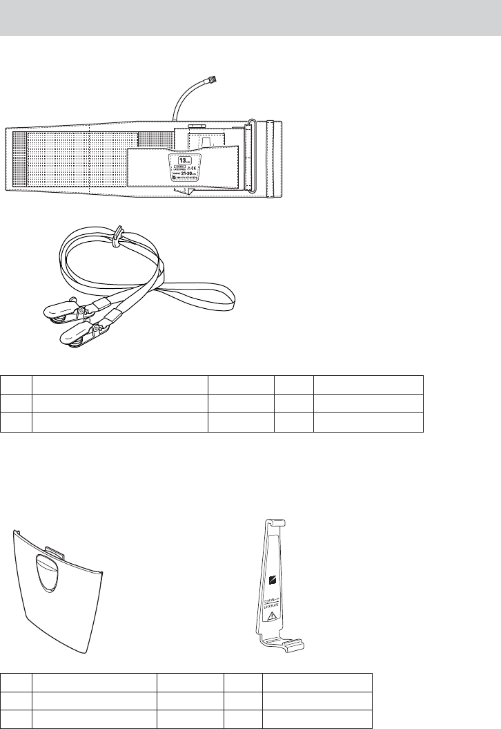
128 Operator’s Manual ZM-540PA/541PA
Standard Accessories
1
2
No. Name Model Q’ty Supply Code No.
1 NIBP cuff for adult, standard YP-503P 1 S937C
2 Strap — 1 Y236
The following parts are available for replacement.
3 4
Lock plate is a standard accessory of
the YP-503P and YP504P NIBP cuff.
No. Name Model Q’ty Supply Code No.
3 Battery case cover — 1 6143-901517A
4 Lock plate — 1 6113-049585

Operator’s Manual ZM-540PA/541PA 129
Options
CAUTION
Only use Nihon Kohden specified electrodes, electrode leads, SpO2 probes, and
NIBP cuffs. Otherwise, the maximum performance from the transmitter cannot be
guaranteed.
Transmitter
• Channel writer, QI-901PK
• NIBP cuff for adult, large (width 15 cm) (for attaching transmitter to patient arm), YP-504P,
supply code no. S937D
ECG/RESP
Name Application Model Q’ty Supply Code No.
Electrode
lead
3 electrodes, clip type,
lead length 80 cm BR-903PA 1 K911A
6 electrodes, clip type,
lead length 80 cm BR-906PA 1 K912A

130 Operator’s Manual ZM-540PA/541PA
SpO2
Name Cable
length
Model/
Code No. Q’ty Supply
Code No.
Finger probe (reusable) 0.6 m TL-201T
1
P225H
1.6 m P225F
Multi-site probe (reusable) 1.6 m TL-220T P225G
Finger probe (reusable)
0.6 m TL-630T1 P310A
1.6 m TL-630T3 P310C
0.6 m TL-631T1 P311A
1.6 m TL-631T3 P311C
SpO2 probe (for adult, disposable)
1.6 m
TL-251T
5
P201A
SpO2 probe (for child, disposable) TL-252T P201B
SpO2 probe (for neonate, disposable) TL-253T P201C
SpO2 probe (for adult, disposable) 0.8 m TL-271T
24
P203A
1.6 m TL-271T3 P203E
SpO2 probe (for child, disposable) 0.8 m TL-272T P203B
1.6 m TL-272T3 P203F
SpO2 probe (for neonate/adult,
disposable)
0.8 m TL-273T P203C
1.6 m TL-273T3 P203G
SpO2 probe (for child/infant,
disposable)
0.8 m TL-274T P203D
1.6 m TL-274T3 P203H
SpO2 probe (for adult/neonate,
disposable)
0.8 m TL-051S
5
P228A
1.6 m TL-052S P228B
SpO2 probe (for child/infant,
disposable)
0.8 m TL-061S P229A
1.6 m TL-062S P229B
COTTONY tape
—
340703 20 P259
Foam tape for TL-051S/052S/
061S/062S —
4 × 25 packages P260
Attachment tape for TL-220T/
251T/252T/253T/630T/631T 3 × 30 packages P263
Probe fastener YS-093P2 30 P267

Operator’s Manual ZM-540PA/541PA 131
NIBP
Name Width
(cm)
Air Hose
Length
(cm)
Model Q’ty Supply
Code No.
Cuff for adult, for
attaching transmitter to
patient arm
Standard 13
15
YP-503P*
1
S937C
Large 15 YP-504P* S937D
Cuff for infant 5
15
YP-960T
1
S943A
Cuff for child Small 7 YP-961T S943B
Standard 10 YP-962T S943C
Cuff for adult Standard 13 YP-963T S944B
Large 15 YP-964T S944C
Disposable cuff for infant 6 17 YP-810P
20
S945C
Disposable cuff for child 8 17 YP-811P S945D
Disposable cuff for adult
Small 10 17 YP-812P S946E
Standard 14 20 YP-813P S946F
Medium
large 15 20 YP-814P S946G
Large 17 20 YP-815P S946H
Extension hose — 150 YN-990P 1 S903
* The lock plate is provided with these NIBP cuffs.

132 Operator’s Manual ZM-540PA/541PA
Transmission Frequencies
Channel: 9002 to 9478
Transmission
frequency
(MHz)
Channel No.
Transmission
frequency
(MHz)
Channel No.
Transmission
frequency
(MHz)
Channel No.
608.0250 9002 608.4375 9035 608.8500 9068
608.0375 9003 608.4500 9036 608.8625 9069
608.0500 9004 608.4625 9037 608.8750 9070
608.0625 9005 608.4750 9038 608.8875 9071
608.0750 9006 608.4875 9039 608.9000 9072
608.0875 9007 608.5000 9040 608.9125 9073
608.1000 9008 608.5125 9041 608.9250 9074
608.1125 9009 608.5250 9042 608.9375 9075
608.1250 9010 608.5375 9043 608.9500 9076
608.1375 9011 608.5500 9044 608.9625 9077
608.1500 9012 608.5625 9045 608.9750 9078
608.1625 9013 608.5750 9046 608.9875 9079
608.1750 9014 608.5875 9047 609.0000 9080
608.1875 9015 608.6000 9048 609.0125 9081
608.2000 9016 608.6125 9049 609.0250 9082
608.2125 9017 608.6250 9050 609.0375 9083
608.2250 9018 608.6375 9051 609.0500 9084
608.2375 9019 608.6500 9052 609.0625 9085
608.2500 9020 608.6625 9053 609.0750 9086
608.2625 9021 608.6750 9054 609.0875 9087
608.2750 9022 608.6875 9055 609.1000 9088
608.2875 9023 608.7000 9056 609.1125 9089
608.3000 9024 608.7125 9057 609.1250 9090
608.3125 9025 608.7250 9058 609.1375 9091
608.3250 9026 608.7375 9059 609.1500 9092
608.3375 9027 608.7500 9060 609.1625 9093
608.3500 9028 608.7625 9061 609.1750 9094
608.3625 9029 608.7750 9062 609.1875 9095
608.3750 9030 608.7875 9063 609.2000 9096
608.3875 9031 608.8000 9064 609.2125 9097
608.4000 9032 608.8125 9065 609.2250 9098
608.4125 9033 608.8250 9066 609.2375 9099
608.4250 9034 608.8375 9067 609.2500 9100

Operator’s Manual ZM-540PA/541PA 133
Transmission
frequency
(MHz)
Channel No.
Transmission
frequency
(MHz)
Channel No.
Transmission
frequency
(MHz)
Channel No.
609.2625 9101 609.7125 9137 610.1625 9173
609.2750 9102 609.7250 9138 610.1750 9174
609.2875 9103 609.7375 9139 610.1875 9175
609.3000 9104 609.7500 9140 610.2000 9176
609.3125 9105 609.7625 9141 610.2125 9177
609.3250 9106 609.7750 9142 610.2250 9178
609.3375 9107 609.7875 9143 610.2375 9179
609.3500 9108 609.8000 9144 610.2500 9180
609.3625 9109 609.8125 9145 610.2625 9181
609.3750 9110 609.8250 9146 610.2750 9182
609.3875 9111 609.8375 9147 610.2875 9183
609.4000 9112 609.8500 9148 610.3000 9184
609.4125 9113 609.8625 9149 610.3125 9185
609.4250 9114 609.8750 9150 610.3250 9186
609.4375 9115 609.8875 9151 610.3375 9187
609.4500 9116 609.9000 9152 610.3500 9188
609.4625 9117 609.9125 9153 610.3625 9189
609.4750 9118 609.9250 9154 610.3750 9190
609.4875 9119 609.9375 9155 610.3875 9191
609.5000 9120 609.9500 9156 610.4000 9192
609.5125 9121 609.9625 9157 610.4125 9193
609.5250 9122 609.9750 9158 610.4250 9194
609.5375 9123 609.9875 9159 610.4375 9195
609.5500 9124 610.0000 9160 610.4500 9196
609.5625 9125 610.0125 9161 610.4625 9197
609.5750 9126 610.0250 9162 610.4750 9198
609.5875 9127 610.0375 9163 610.4875 9199
609.6000 9128 610.0500 9164 610.5000 9200
609.6125 9129 610.0625 9165 610.5125 9201
609.6250 9130 610.0750 9166 610.5250 9202
609.6375 9131 610.0875 9167 610.5375 9203
609.6500 9132 610.1000 9168 610.5500 9204
609.6625 9133 610.1125 9169 610.5625 9205
609.6750 9134 610.1250 9170 610.5750 9206
609.6875 9135 610.1375 9171 610.5875 9207
609.7000 9136 610.1500 9172 610.6000 9208

134 Operator’s Manual ZM-540PA/541PA
Transmission
frequency
(MHz)
Channel No.
Transmission
frequency
(MHz)
Channel No.
Transmission
frequency
(MHz)
Channel No.
610.6125 9209 611.0625 9245 611.5125 9281
610.6250 9210 611.0750 9246 611.5250 9282
610.6375 9211 611.0875 9247 611.5375 9283
610.6500 9212 611.1000 9248 611.5500 9284
610.6625 9213 611.1125 9249 611.5625 9285
610.6750 9214 611.1250 9250 611.5750 9286
610.6875 9215 611.1375 9251 611.5875 9287
610.7000 9216 611.1500 9252 611.6000 9288
610.7125 9217 611.1625 9253 611.6125 9289
610.7250 9218 611.1750 9254 611.6250 9290
610.7375 9219 611.1875 9255 611.6375 9291
610.7500 9220 611.2000 9256 611.6500 9292
610.7625 9221 611.2125 9257 611.6625 9293
610.7750 9222 611.2250 9258 611.6750 9294
610.7875 9223 611.2375 9259 611.6875 9295
610.8000 9224 611.2500 9260 611.7000 9296
610.8125 9225 611.2625 9261 611.7125 9297
610.8250 9226 611.2750 9262 611.7250 9298
610.8375 9227 611.2875 9263 611.7375 9299
610.8500 9228 611.3000 9264 611.7500 9300
610.8625 9229 611.3125 9265 611.7625 9301
610.8750 9230 611.3250 9266 611.7750 9302
610.8875 9231 611.3375 9267 611.7875 9303
610.9000 9232 611.3500 9268 611.8000 9304
610.9125 9233 611.3625 9269 611.8125 9305
610.9250 9234 611.3750 9270 611.8250 9306
610.9375 9235 611.3875 9271 611.8375 9307
610.9500 9236 611.4000 9272 611.8500 9308
610.9625 9237 611.4125 9273 611.8625 9309
610.9750 9238 611.4250 9274 611.8750 9310
610.9875 9239 611.4375 9275 611.8875 9311
611.0000 9240 611.4500 9276 611.9000 9312
611.0125 9241 611.4625 9277 611.9125 9313
611.0250 9242 611.4750 9278 611.9250 9314
611.0375 9243 611.4875 9279 611.9375 9315
611.0500 9244 611.5000 9280 611.9500 9316

Operator’s Manual ZM-540PA/541PA 135
Transmission
frequency
(MHz)
Channel No.
Transmission
frequency
(MHz)
Channel No.
Transmission
frequency
(MHz)
Channel No.
611.9625 9317 612.4125 9353 612.8625 9389
611.9750 9318 612.4250 9354 612.8750 9390
611.9875 9319 612.4375 9355 612.8875 9391
612.0000 9320 612.4500 9356 612.9000 9392
612.0125 9321 612.4625 9357 612.9125 9393
612.0250 9322 612.4750 9358 612.9250 9394
612.0375 9323 612.4875 9359 612.9375 9395
612.0500 9324 612.5000 9360 612.9500 9396
612.0625 9325 612.5125 9361 612.9625 9397
612.0750 9326 612.5250 9362 612.9750 9398
612.0875 9327 612.5375 9363 612.9875 9399
612.1000 9328 612.5500 9364 613.0000 9400
612.1125 9329 612.5625 9365 613.0125 9401
612.1250 9330 612.5750 9366 613.0250 9402
612.1375 9331 612.5875 9367 613.0375 9403
612.1500 9332 612.6000 9368 613.0500 9404
612.1625 9333 612.6125 9369 613.0625 9405
612.1750 9334 612.6250 9370 613.0750 9406
612.1875 9335 612.6375 9371 613.0875 9407
612.2000 9336 612.6500 9372 613.1000 9408
612.2125 9337 612.6625 9373 613.1125 9409
612.2250 9338 612.6750 9374 613.1250 9410
612.2375 9339 612.6875 9375 613.1375 9411
612.2500 9340 612.7000 9376 613.1500 9412
612.2625 9341 612.7125 9377 613.1625 9413
612.2750 9342 612.7250 9378 613.1750 9414
612.2875 9343 612.7375 9379 613.1875 9415
612.3000 9344 612.7500 9380 613.2000 9416
612.3125 9345 612.7625 9381 613.2125 9417
612.3250 9346 612.7750 9382 613.2250 9418
612.3375 9347 612.7875 9383 613.2375 9419
612.3500 9348 612.8000 9384 613.2500 9420
612.3625 9349 612.8125 9385 613.2625 9421
612.3750 9350 612.8250 9386 613.2750 9422
612.3875 9351 612.8375 9387 613.2875 9423
612.4000 9352 612.8500 9388 613.3000 9424

136 Operator’s Manual ZM-540PA/541PA
Transmission
frequency
(MHz)
Channel No.
Transmission
frequency
(MHz)
Channel No.
Transmission
frequency
(MHz)
Channel No.
613.3125 9425 613.5375 9443 613.7625 9461
613.3250 9426 613.5500 9444 613.7750 9462
613.3375 9427 613.5625 9445 613.7875 9463
613.3500 9428 613.5750 9446 613.8000 9464
613.3625 9429 613.5875 9447 613.8125 9465
613.3750 9430 613.6000 9448 613.8250 9466
613.3875 9431 613.6125 9449 613.8375 9467
613.4000 9432 613.6250 9450 613.8500 9468
613.4125 9433 613.6375 9451 613.8625 9469
613.4250 9434 613.6500 9452 613.8750 9470
613.4375 9435 613.6625 9453 613.8875 9471
613.4500 9436 613.6750 9454 613.9000 9472
613.4625 9437 613.6875 9455 613.9125 9473
613.4750 9438 613.7000 9456 613.9250 9474
613.4875 9439 613.7125 9457 613.9375 9475
613.5000 9440 613.7250 9458 613.9500 9476
613.5125 9441 613.7375 9459 613.9625 9477
613.5250 9442 613.7500 9460 613.9750 9478

Operator’s Manual ZM-540PA/541PA 137
Channel: E002 to E398
Transmission
frequency
(MHz)
Channel
No.
Transmission
frequency
(MHz)
Channel
No.
Transmission
frequency
(MHz)
Channel
No.
1395.0250 E002 1395.4625 E037 1395.9000 E072
1395.0375 E003 1395.4750 E038 1395.9125 E073
1395.0500 E004 1395.4875 E039 1395.9250 E074
1395.0625 E005 1395.5000 E040 1395.9375 E075
1395.0750 E006 1395.5125 E041 1395.9500 E076
1395.0875 E007 1395.5250 E042 1395.9625 E077
1395.1000 E008 1395.5375 E043 1395.9750 E078
1395.1125 E009 1395.5500 E044 1395.9875 E079
1395.1250 E010 1395.5625 E045 1396.0000 E080
1395.1375 E011 1395.5750 E046 1396.0125 E081
1395.1500 E012 1395.5875 E047 1396.0250 E082
1395.1625 E013 1395.6000 E048 1396.0375 E083
1395.1750 E014 1395.6125 E049 1396.0500 E084
1395.1875 E015 1395.6250 E050 1396.0625 E085
1395.2000 E016 1395.6375 E051 1396.0750 E086
1395.2125 E017 1395.6500 E052 1396.0875 E087
1395.2250 E018 1395.6625 E053 1396.1000 E088
1395.2375 E019 1395.6750 E054 1396.1125 E089
1395.2500 E020 1395.6875 E055 1396.1250 E090
1395.2625 E021 1395.7000 E056 1396.1375 E091
1395.2750 E022 1395.7125 E057 1396.1500 E092
1395.2875 E023 1395.7250 E058 1396.1625 E093
1395.3000 E024 1395.7375 E059 1396.1750 E094
1395.3125 E025 1395.7500 E060 1396.1875 E095
1395.3250 E026 1395.7625 E061 1396.2000 E096
1395.3375 E027 1395.7750 E062 1396.2125 E097
1395.3500 E028 1395.7875 E063 1396.2250 E098
1395.3625 E029 1395.8000 E064 1396.2375 E099
1395.3750 E030 1395.8125 E065 1396.2500 E100
1395.3875 E031 1395.8250 E066 1396.2625 E101
1395.4000 E032 1395.8375 E067 1396.2750 E102
1395.4125 E033 1395.8500 E068 1396.2875 E103
1395.4250 E034 1395.8625 E069 1396.3000 E104
1395.4375 E035 1395.8750 E070 1396.3125 E105
1395.4500 E036 1395.8875 E071 1396.3250 E106

138 Operator’s Manual ZM-540PA/541PA
Transmission
frequency
(MHz)
Channel
No.
Transmission
frequency
(MHz)
Channel
No.
Transmission
frequency
(MHz)
Channel
No.
1396.3375 E107 1396.7875 E143 1397.2375 E179
1396.3500 E108 1396.8000 E144 1397.2500 E180
1396.3625 E109 1396.8125 E145 1397.2625 E181
1396.3750 E110 1396.8250 E146 1397.2750 E182
1396.3875 E111 1396.8375 E147 1397.2875 E183
1396.4000 E112 1396.8500 E148 1397.3000 E184
1396.4125 E113 1396.8625 E149 1397.3125 E185
1396.4250 E114 1396.8750 E150 1397.3250 E186
1396.4375 E115 1396.8875 E151 1397.3375 E187
1396.4500 E116 1396.9000 E152 1397.3500 E188
1396.4625 E117 1396.9125 E153 1397.3625 E189
1396.4750 E118 1396.9250 E154 1397.3750 E190
1396.4875 E119 1396.9375 E155 1397.3875 E191
1396.5000 E120 1396.9500 E156 1397.4000 E192
1396.5125 E121 1396.9625 E157 1397.4125 E193
1396.5250 E122 1396.9750 E158 1397.4250 E194
1396.5375 E123 1396.9875 E159 1397.4375 E195
1396.5500 E124 1397.0000 E160 1397.4500 E196
1396.5625 E125 1397.0125 E161 1397.4625 E197
1396.5750 E126 1397.0250 E162 1397.4750 E198
1396.5875 E127 1397.0375 E163 1397.4875 E199
1396.6000 E128 1397.0500 E164 1397.5000 E200
1396.6125 E129 1397.0625 E165 1397.5125 E201
1396.6250 E130 1397.0750 E166 1397.5250 E202
1396.6375 E131 1397.0875 E167 1397.5375 E203
1396.6500 E132 1397.1000 E168 1397.5500 E204
1396.6625 E133 1397.1125 E169 1397.5625 E205
1396.6750 E134 1397.1250 E170 1397.5750 E206
1396.6875 E135 1397.1375 E171 1397.5875 E207
1396.7000 E136 1397.1500 E172 1397.6000 E208
1396.7125 E137 1397.1625 E173 1397.6125 E209
1396.7250 E138 1397.1750 E174 1397.6250 E210
1396.7375 E139 1397.1875 E175 1397.6375 E211
1396.7500 E140 1397.2000 E176 1397.6500 E212
1396.7625 E141 1397.2125 E177 1397.6625 E213
1396.7750 E142 1397.2250 E178 1397.6750 E214

Operator’s Manual ZM-540PA/541PA 139
Transmission
frequency
(MHz)
Channel
No.
Transmission
frequency
(MHz)
Channel
No.
Transmission
frequency
(MHz)
Channel
No.
1397.6875 E215 1398.1375 E251 1398.5875 E287
1397.7000 E216 1398.1500 E252 1398.6000 E288
1397.7125 E217 1398.1625 E253 1398.6125 E289
1397.7250 E218 1398.1750 E254 1398.6250 E290
1397.7375 E219 1398.1875 E255 1398.6375 E291
1397.7500 E220 1398.2000 E256 1398.6500 E292
1397.7625 E221 1398.2125 E257 1398.6625 E293
1397.7750 E222 1398.2250 E258 1398.6750 E294
1397.7875 E223 1398.2375 E259 1398.6875 E295
1397.8000 E224 1398.2500 E260 1398.7000 E296
1397.8125 E225 1398.2625 E261 1398.7125 E297
1397.8250 E226 1398.2750 E262 1398.7250 E298
1397.8375 E227 1398.2875 E263 1398.7375 E299
1397.8500 E228 1398.3000 E264 1398.7500 E300
1397.8625 E229 1398.3125 E265 1398.7625 E301
1397.8750 E230 1398.3250 E266 1398.7750 E302
1397.8875 E231 1398.3375 E267 1398.7875 E303
1397.9000 E232 1398.3500 E268 1398.8000 E304
1397.9125 E233 1398.3625 E269 1398.8125 E305
1397.9250 E234 1398.3750 E270 1398.8250 E306
1397.9375 E235 1398.3875 E271 1398.8375 E307
1397.9500 E236 1398.4000 E272 1398.8500 E308
1397.9625 E237 1398.4125 E273 1398.8625 E309
1397.9750 E238 1398.4250 E274 1398.8750 E310
1397.9875 E239 1398.4375 E275 1398.8875 E311
1398.0000 E240 1398.4500 E276 1398.9000 E312
1398.0125 E241 1398.4625 E277 1398.9125 E313
1398.0250 E242 1398.4750 E278 1398.9250 E314
1398.0375 E243 1398.4875 E279 1398.9375 E315
1398.0500 E244 1398.5000 E280 1398.9500 E316
1398.0625 E245 1398.5125 E281 1398.9625 E317
1398.0750 E246 1398.5250 E282 1398.9750 E318
1398.0875 E247 1398.5375 E283 1398.9875 E319
1398.1000 E248 1398.5500 E284 1399.0000 E320
1398.1125 E249 1398.5625 E285 1399.0125 E321
1398.1250 E250 1398.5750 E286 1399.0250 E322

140 Operator’s Manual ZM-540PA/541PA
Transmission
frequency
(MHz)
Channel
No.
Transmission
frequency
(MHz)
Channel
No.
Transmission
frequency
(MHz)
Channel
No.
1399.0375 E323 1399.4625 E357 1399.8875 E391
1399.0500 E324 1399.4750 E358 1399.9000 E392
1399.0625 E325 1399.4875 E359 1399.9125 E393
1399.0750 E326 1399.5000 E360 1399.9250 E394
1399.0875 E327 1399.5125 E361 1399.9375 E395
1399.1000 E328 1399.5250 E362 1399.9500 E396
1399.1125 E329 1399.5375 E363 1399.9625 E397
1399.1250 E330 1399.5500 E364 1399.9750 E398
1399.1375 E331 1399.5625 E365
1399.1500 E332 1399.5750 E366
1399.1625 E333 1399.5875 E367
1399.1750 E334 1399.6000 E368
1399.1875 E335 1399.6125 E369
1399.2000 E336 1399.6250 E370
1399.2125 E337 1399.6375 E371
1399.2250 E338 1399.6500 E372
1399.2375 E339 1399.6625 E373
1399.2500 E340 1399.6750 E374
1399.2625 E341 1399.6875 E375
1399.2750 E342 1399.7000 E376
1399.2875 E343 1399.7125 E377
1399.3000 E344 1399.7250 E378
1399.3125 E345 1399.7375 E379
1399.3250 E346 1399.7500 E380
1399.3375 E347 1399.7625 E381
1399.3500 E348 1399.7750 E382
1399.3625 E349 1399.7875 E383
1399.3750 E350 1399.8000 E384
1399.3875 E351 1399.8125 E385
1399.4000 E352 1399.8250 E386
1399.4125 E353 1399.8375 E387
1399.4250 E354 1399.8500 E388
1399.4375 E355 1399.8625 E389
1399.4500 E356 1399.8750 E390

Operator’s Manual ZM-540PA/541PA 141
Channel: E502 to E898
Transmission
frequency
(MHz)
Channel
No.
Transmission
frequency
(MHz)
Channel
No.
Transmission
frequency
(MHz)
Channel
No.
1427.0250 E502 1427.4500 E536 1427.8750 E570
1427.0375 E503 1427.4625 E537 1427.8875 E571
1427.0500 E504 1427.4750 E538 1427.9000 E572
1427.0625 E505 1427.4875 E539 1427.9125 E573
1427.0750 E506 1427.5000 E540 1427.9250 E574
1427.0875 E507 1427.5125 E541 1427.9375 E575
1427.1000 E508 1427.5250 E542 1427.9500 E576
1427.1125 E509 1427.5375 E543 1427.9625 E577
1427.1250 E510 1427.5500 E544 1427.9750 E578
1427.1375 E511 1427.5625 E545 1427.9875 E579
1427.1500 E512 1427.5750 E546 1428.0000 E580
1427.1625 E513 1427.5875 E547 1428.0125 E581
1427.1750 E514 1427.6000 E548 1428.0250 E582
1427.1875 E515 1427.6125 E549 1428.0375 E583
1427.2000 E516 1427.6250 E550 1428.0500 E584
1427.2125 E517 1427.6375 E551 1428.0625 E585
1427.2250 E518 1427.6500 E552 1428.0750 E586
1427.2375 E519 1427.6625 E553 1428.0875 E587
1427.2500 E520 1427.6750 E554 1428.1000 E588
1427.2625 E521 1427.6875 E555 1428.1125 E589
1427.2750 E522 1427.7000 E556 1428.1250 E590
1427.2875 E523 1427.7125 E557 1428.1375 E591
1427.3000 E524 1427.7250 E558 1428.1500 E592
1427.3125 E525 1427.7375 E559 1428.1625 E593
1427.3250 E526 1427.7500 E560 1428.1750 E594
1427.3375 E527 1427.7625 E561 1428.1875 E595
1427.3500 E528 1427.7750 E562 1428.2000 E596
1427.3625 E529 1427.7875 E563 1428.2125 E597
1427.3750 E530 1427.8000 E564 1428.2250 E598
1427.3875 E531 1427.8125 E565 1428.2375 E599
1427.4000 E532 1427.8250 E566 1428.2500 E600
1427.4125 E533 1427.8375 E567 1428.2625 E601
1427.4250 E534 1427.8500 E568 1428.2750 E602
1427.4375 E535 1427.8625 E569 1428.2875 E603

142 Operator’s Manual ZM-540PA/541PA
Transmission
frequency
(MHz)
Channel
No.
Transmission
frequency
(MHz)
Channel
No.
Transmission
frequency
(MHz)
Channel
No.
1428.3000 E604 1428.7500 E640 1429.2000 E676
1428.3125 E605 1428.7625 E641 1429.2125 E677
1428.3250 E606 1428.7750 E642 1429.2250 E678
1428.3375 E607 1428.7875 E643 1429.2375 E679
1428.3500 E608 1428.8000 E644 1429.2500 E680
1428.3625 E609 1428.8125 E645 1429.2625 E681
1428.3750 E610 1428.8250 E646 1429.2750 E682
1428.3875 E611 1428.8375 E647 1429.2875 E683
1428.4000 E612 1428.8500 E648 1429.3000 E684
1428.4125 E613 1428.8625 E649 1429.3125 E685
1428.4250 E614 1428.8750 E650 1429.3250 E686
1428.4375 E615 1428.8875 E651 1429.3375 E687
1428.4500 E616 1428.9000 E652 1429.3500 E688
1428.4625 E617 1428.9125 E653 1429.3625 E689
1428.4750 E618 1428.9250 E654 1429.3750 E690
1428.4875 E619 1428.9375 E655 1429.3875 E691
1428.5000 E620 1428.9500 E656 1429.4000 E692
1428.5125 E621 1428.9625 E657 1429.4125 E693
1428.5250 E622 1428.9750 E658 1429.4250 E694
1428.5375 E623 1428.9875 E659 1429.4375 E695
1428.5500 E624 1429.0000 E660 1429.4500 E696
1428.5625 E625 1429.0125 E661 1429.4625 E697
1428.5750 E626 1429.0250 E662 1429.4750 E698
1428.5875 E627 1429.0375 E663 1429.4875 E699
1428.6000 E628 1429.0500 E664 1429.5000 E700
1428.6125 E629 1429.0625 E665 1429.5125 E701
1428.6250 E630 1429.0750 E666 1429.5250 E702
1428.6375 E631 1429.0875 E667 1429.5375 E703
1428.6500 E632 1429.1000 E668 1429.5500 E704
1428.6625 E633 1429.1125 E669 1429.5625 E705
1428.6750 E634 1429.1250 E670 1429.5750 E706
1428.6875 E635 1429.1375 E671 1429.5875 E707
1428.7000 E636 1429.1500 E672 1429.6000 E708
1428.7125 E637 1429.1625 E673 1429.6125 E709
1428.7250 E638 1429.1750 E674 1429.6250 E710
1428.7375 E639 1429.1875 E675 1429.6375 E711

Operator’s Manual ZM-540PA/541PA 143
Transmission
frequency
(MHz)
Channel
No.
Transmission
frequency
(MHz)
Channel
No.
Transmission
frequency
(MHz)
Channel
No.
1429.6500 E712 1430.1000 E748 1430.5500 E784
1429.6625 E713 1430.1125 E749 1430.5625 E785
1429.6750 E714 1430.1250 E750 1430.5750 E786
1429.6875 E715 1430.1375 E751 1430.5875 E787
1429.7000 E716 1430.1500 E752 1430.6000 E788
1429.7125 E717 1430.1625 E753 1430.6125 E789
1429.7250 E718 1430.1750 E754 1430.6250 E790
1429.7375 E719 1430.1875 E755 1430.6375 E791
1429.7500 E720 1430.2000 E756 1430.6500 E792
1429.7625 E721 1430.2125 E757 1430.6625 E793
1429.7750 E722 1430.2250 E758 1430.6750 E794
1429.7875 E723 1430.2375 E759 1430.6875 E795
1429.8000 E724 1430.2500 E760 1430.7000 E796
1429.8125 E725 1430.2625 E761 1430.7125 E797
1429.8250 E726 1430.2750 E762 1430.7250 E798
1429.8375 E727 1430.2875 E763 1430.7375 E799
1429.8500 E728 1430.3000 E764 1430.7500 E800
1429.8625 E729 1430.3125 E765 1430.7625 E801
1429.8750 E730 1430.3250 E766 1430.7750 E802
1429.8875 E731 1430.3375 E767 1430.7875 E803
1429.9000 E732 1430.3500 E768 1430.8000 E804
1429.9125 E733 1430.3625 E769 1430.8125 E805
1429.9250 E734 1430.3750 E770 1430.8250 E806
1429.9375 E735 1430.3875 E771 1430.8375 E807
1429.9500 E736 1430.4000 E772 1430.8500 E808
1429.9625 E737 1430.4125 E773 1430.8625 E809
1429.9750 E738 1430.4250 E774 1430.8750 E810
1429.9875 E739 1430.4375 E775 1430.8875 E811
1430.0000 E740 1430.4500 E776 1430.9000 E812
1430.0125 E741 1430.4625 E777 1430.9125 E813
1430.0250 E742 1430.4750 E778 1430.9250 E814
1430.0375 E743 1430.4875 E779 1430.9375 E815
1430.0500 E744 1430.5000 E780 1430.9500 E816
1430.0625 E745 1430.5125 E781 1430.9625 E817
1430.0750 E746 1430.5250 E782 1430.9750 E818
1430.0875 E747 1430.5375 E783 1430.9875 E819

144 Operator’s Manual ZM-540PA/541PA
Transmission
frequency
(MHz)
Channel
No.
Transmission
frequency
(MHz)
Channel
No.
Transmission
frequency
(MHz)
Channel
No.
1431.0000 E820 1431.4375 E855 1431.8750 E890
1431.0125 E821 1431.4500 E856 1431.8875 E891
1431.0250 E822 1431.4625 E857 1431.9000 E892
1431.0375 E823 1431.4750 E858 1431.9125 E893
1431.0500 E824 1431.4875 E859 1431.9250 E894
1431.0625 E825 1431.5000 E860 1431.9375 E895
1431.0750 E826 1431.5125 E861 1431.9500 E896
1431.0875 E827 1431.5250 E862 1431.9625 E897
1431.1000 E828 1431.5375 E863 1431.9750 E898
1431.1125 E829 1431.5500 E864
1431.1250 E830 1431.5625 E865
1431.1375 E831 1431.5750 E866
1431.1500 E832 1431.5875 E867
1431.1625 E833 1431.6000 E868
1431.1750 E834 1431.6125 E869
1431.1875 E835 1431.6250 E870
1431.2000 E836 1431.6375 E871
1431.2125 E837 1431.6500 E872
1431.2250 E838 1431.6625 E873
1431.2375 E839 1431.6750 E874
1431.2500 E840 1431.6875 E875
1431.2625 E841 1431.7000 E876
1431.2750 E842 1431.7125 E877
1431.2875 E843 1431.7250 E878
1431.3000 E844 1431.7375 E879
1431.3125 E845 1431.7500 E880
1431.3250 E846 1431.7625 E881
1431.3375 E847 1431.7750 E882
1431.3500 E848 1431.7875 E883
1431.3625 E849 1431.8000 E884
1431.3750 E850 1431.8125 E885
1431.3875 E851 1431.8250 E886
1431.4000 E852 1431.8375 E887
1431.4125 E853 1431.8500 E888
1431.4250 E854 1431.8625 E889