User Manual

OEM/I t t I t ll ti M l
OEM/I
n
t
egra
t
ors
I
ns
t
a
ll
a
ti
on
M
anua
l
Version 1.1
April 07. 2014
This document is confidential and subject to change

1 The RF module limited to OEM installation ONLY
•
1
.
The
RF
module
limited
to
OEM
installation
ONLY
.
•The OEM integrator is responsible for the compliance to all the rules that apply to the product into which this certified
•RF module is integrated.
•2. This device complies with part 15 of the FCC Rules. Operation is subject to the following two conditions: (1) This device may
•not cause harmful interference, and (2) this device must accept any interference received, including interference that may
•cause undesired operation.
•3. This equipment has been tested and found to comply with the limits for a Class B digital device, pursuant to part 15 of the
•FCC Rules. These limits are designed to provide reasonable protection against harmful interference in a residential installation.
•This e
q
ui
p
ment
g
enerates uses and can radiate radio fre
q
uenc
y
ener
gy
and
,
if not installed and used in accordance with the
qp g q y gy ,
•instructions, may cause harmful interference to radio communications. However, there is no guarantee that interference will
•not occur in a particular installation. If this equipment does cause harmful interference to radio or television reception, which
•can be determined by turning the equipment off and on, the user is encouraged to try to correct the interference by one or
•more of the following measures:
•
Reorient or relocate the receiving antenna
•
-
Reorient
or
relocate
the
receiving
antenna
.
•- Increase the separation between the equipment and receiver.
•- l Connect the equipment into an outlet on a circuit different from that to which the receiver is connected.
•- l Consult the dealer or an experienced radio/TV technician for help.
•FCC Caution
•Any changes or modifications not expressly approved by the party responsible for compliance could void the user's authority to
operate this equipment. This transmitter must not be co-located or operating in conjunction with any other antenna or ransmitter.
•Radiation Exposure Statement
•This equipment complies with FCC radiation exposure limits set forth for an uncontrolled environment. This equipment should be
•installed and operated with minimum distance 20cm between the radiator & your body.
2010-01-08 This document is confidential and
subject to change 2

This device is intended only for OEM integrators under the following conditions:
•
This
device
is
intended
only
for
OEM
integrators
under
the
following
conditions:
•The antenna must be installed such that 20 cm is maintained between the antenna and users, and The transmitter module may
•not be co-located with any other transmitter or antenna. As long as 2 conditions above are met, further transmitter test will not
•be required. However, the OEM integrator is still responsible for testing their end-product for any additional compliance
•requirements required with this module installed.
•
•IMPORTANT NOTE:
•In the event that these conditions cannot be met (for example certain laptop configurations or colocation with another
•transmitter), then the FCC authorization is no longer considered valid and the FCC ID cannot be used on the final product. In
•these circumstances
,
the OEM inte
g
rator will be res
p
onsible for re-evaluatin
g
the end
p
roduct
(
includin
g
the transmitter
)
and
,g p
gp(g )
•obtaining a separate FCC authorization.
•End Product Labeling
•This transmitter module is authorized only for use in device where the antenna may be installed such that 20 cm may be
•
maintained between the antenna and users The final end product must be labeled in a visible area with the following:
•
maintained
between
the
antenna
and
users
.
The
final
end
product
must
be
labeled
in
a
visible
area
with
the
following:
•“Contains FCC ID: ZD7-WiMi300”.
•The grantee's FCC ID can be used only when all FCC/ IC compliance requirements are met.
•Manual Information To the End User
•The OEM integrator has to be aware not to provide information to the end user regarding how to
•install or remove this RF module in the user's manual of the end product which integrates this module.
•The end user manual shall include all required regulatory information/warning as show in this manual.
•O
p
erations in 5.15-5.25GHz band are for indoor use onl
y
.
p
y
2010-01-08 This document is confidential and
subject to change 3

Features
Key Features :
•
3x3 antenna Configuration
• 802.11n Network Standards (HT 40 only)
• Modulation modes: BPSK, QPSK, 16QAM and 64QAM
• WPS Certified- Wireless Protected Setu
p
for eas
y
set u
p
and securit
y
confi
g
uration
pyp yg
• Optimal channel selection and connection management
•
Seamless channel switch
under interference
• 40 MHz bandwidth support.
• 300MHz PHY Rate Support and STBC Support for Extended Range
• Antenna: 3x IPex Connectors (3T/3R)
-
UFL
•
Antenna:
3x
IPex
Connectors
(3T/3R)
U
.
FL
• MAC Filtering - No Restriction Mode, White List Mode, Black List Mode; Up to 32 connections
• WDS Enables network management units to collect statistics and manage the device remotely
• Support Low Power Mode
St d d & C tifi ti
St
an
d
ar
d
&
C
er
tifi
ca
ti
ons
:
• FCC
• RoHS Compliance
2014-04-07 4
This document is confidential and subject to change

Specification
Chipset
Mac/BB Processor Lantiq PSB8231
RF Chip Lantiq PSB8301
Radio
Standards 2009 IEEE 802.11a, IEEE 802.11n
Antenna U.FL 3 x Ipex Connectors (3T/3R)
RF connector impedance 50 ohm
Operating Frequency 802.11n : 5.190 ~ 5.230GHz, 5.755 ~ 5.795GHz
Modulation IEEE 802.11n : OFDM
Ctifiti
C
er
tifi
ca
ti
ons
Output Power
(Per Antenna @ -25dB EVM)
802.11n HT40 : 5.190 ~ 5.230GHz 17.0 +/- 1dBm (Avg)
5.755 ~ 5.795GHz 25.0 +/- 1dBm (PK)
802.11a 64QAM 5/6 <= -75dBm
802.11a BPSK ½ <= -88dBm
802.11n HT40
,
64
Q
AM 5
/
6 <= -75dBm
(@
3 antennas
)
Receive Sensitivity (PER <10%)
,Q /
(@ )
802.11n HT20, 64QAM 5/6 <= -78dBm (@3 antennas)
802.11n HT40, BPSK 1/2 <= -92dBm (@3 antennas)
802.11n HT20, BPSK 1/2 <= -94dBm (@3 antennas)
2014-04-07 5
This document is confidential and subject to change
Receiver Max Power
Sensitivity (PER < 10%) -20dBm

Specification
Power Supply
Input Voltage / Average Power 3.3V / 5.5W
Environmental
Output Power
(Per Antenna @ -25dB EVM)
Temperature Humidity
0 ~ 50 OC 10% to 85% Non-Condensing
-20 ~ 85 OC 5% to 90% Non-Condensing
Utility
Driver Support Linux 2.6.33
Wireless Statistics Link quality, RSSI, noise level packet statistics
Dimensions
Dimensions(PCBA) 50.95mm x 32 mm
Manufacturing compliant Lead-free RoHS
2014-04-07 6
This document is confidential and subject to change

Specification
Power Supply
Input Voltage / Average Power 3.3V / 5.5W
Environmental
Output Power
(Per Antenna @ -25dB EVM)
Temperature Humidity
0 ~ 50 OC 10% to 85% Non-Condensing
-20 ~ 85 OC 5% to 90% Non-Condensing
Utility
Driver Support Linux 2.6.33
Wireless Statistics Link quality, RSSI, noise level packet statistics
Dimensions
Dimensions(PCBA) 50.95mm x 32 mm
Manufacturing compliant Lead-free RoHS
2014-04-07 7
This document is confidential and subject to change
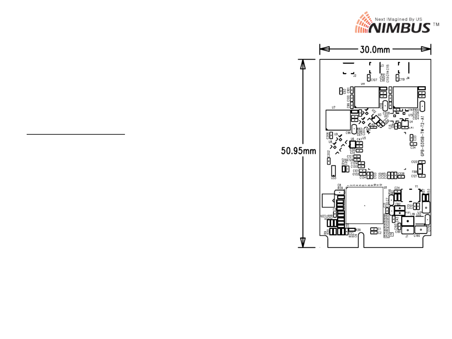
Mechanical Specification
PCB Dimension:
PCB
Dimension:
•
Width : 30.0mm
•
Height : 50.95mm
•
Thickness
:
1.0 mm
Thickness
1.0
mm
•
PCB Form Factor complied with PCI express Mini Card Electromechanical Specification Rev 1.2(Oct. 26,
2007), Figure 2-3 : Full Mini Card
2014-04-07 8
This document is confidential and subject to change

Pin Out Definitions – 1 of 2
Pi #
N
Pi #
N
Pi
n
#
N
ame
Pi
n
#
N
ame
51 Reserved 52 +3.3V aux
49 Reserved 50 GND
47 Reserved 48 +1.5V
45 Reserved 46 LED_WPAN#
43 GND 44 LED_WLAN#
41 +3.3V aux 42 LED_WWAN#
39
33V
40
GND
39
+
3
.
3V
aux
40
GND
37 GND 38 USB_Dp
35 GND 36 USB_Dn
33 PETp0 34 GND
31 PETn0 32 SMB_DATA
29 GND 30 SMB_CLK
27 GND 28 +1.5V
25
PERp0
26
GND
25
PERp0
26
GND
23 PERn0 24 +3.3V aux
21 GND 22 PERST#
19 Reserved 20 W_DISABLE#
17 Reserved 18 GND
Mechanical Key
15 GND 16 Reserved
2014-04-07 9
This document is confidential and subject to change

Pin Out Definitions – 2 of 2
Pin # Name Pin # Name
13 REFCLKp 14 Reserved
11 REFCLKn 12 Reserved
9GND 10Reserved
7 CLKREQ# 8 Reserved
5 Reserved 6 +1.5V
3 Reserved 4 GND
1 WAKE# 2 +3.3V aux
2014-04-07 10
This document is confidential and subject to change
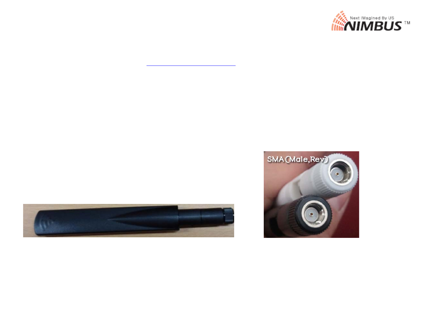
Antenna Spec
Manufacturer : Antenna-pro www.antenna-pro.com
Model NO. : KMDA5158-06SMA
At T 24 58GD lB d
WiFi
Di l t
A
n
t
enna
T
y
p
e :
2
.
4
~
5
.
8G
D
ua
l
B
an
d
WiFi
Dip
o
l
e an
t
enna
(4 dBi(2.4 GHz), 7 dBi(5 GHz))
Antenna connect : SMA (Male Rev)
2014-04-07 11
This document is confidential and subject to change