Nokia Bell G240WE GPON ONU User Manual Nokia WiFi Gateway 3 Product Guide
Nokia Shanghai Bell Co. Ltd. GPON ONU Nokia WiFi Gateway 3 Product Guide
UserManual.wiki
>
Nokia Bell
>
G240WE User Manual
Users Manual
Navigation menu
Upload a User Manual
Namespaces
Wiki Guide
HTML
PDF
Info
Views
User Manual
Discussion / Help
Navigation

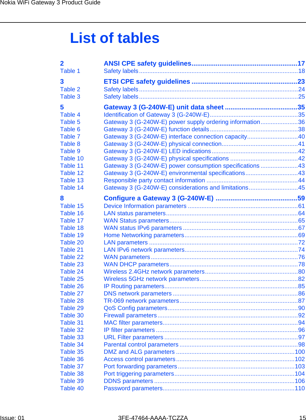
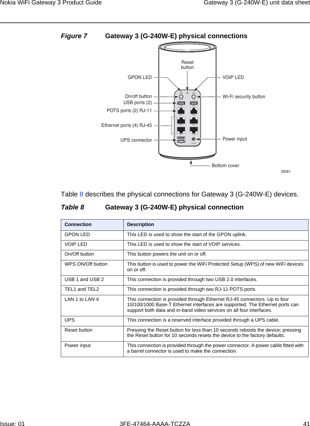
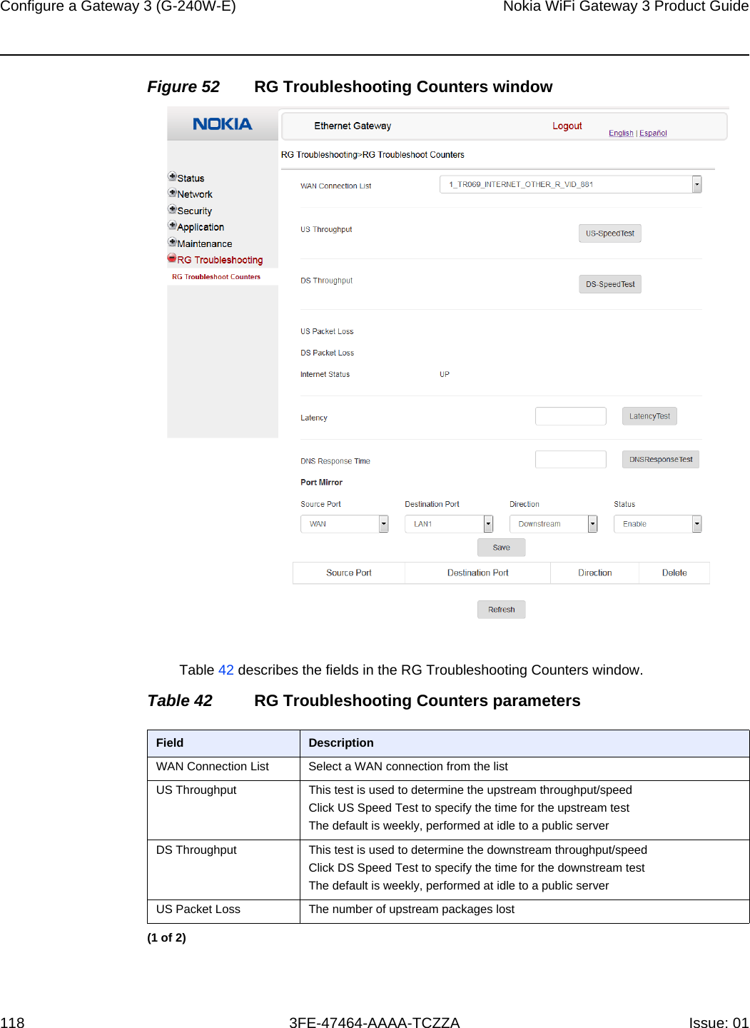
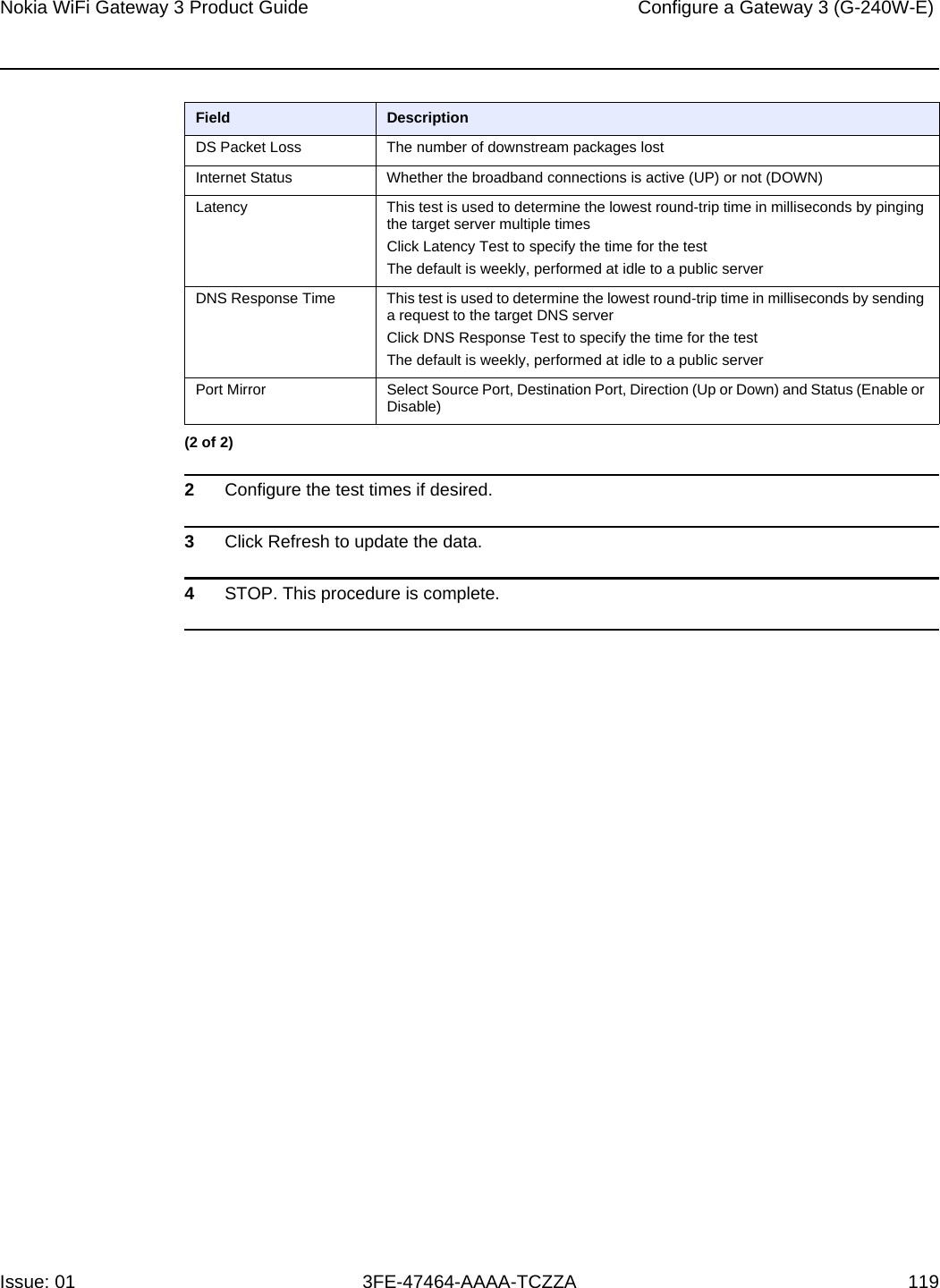
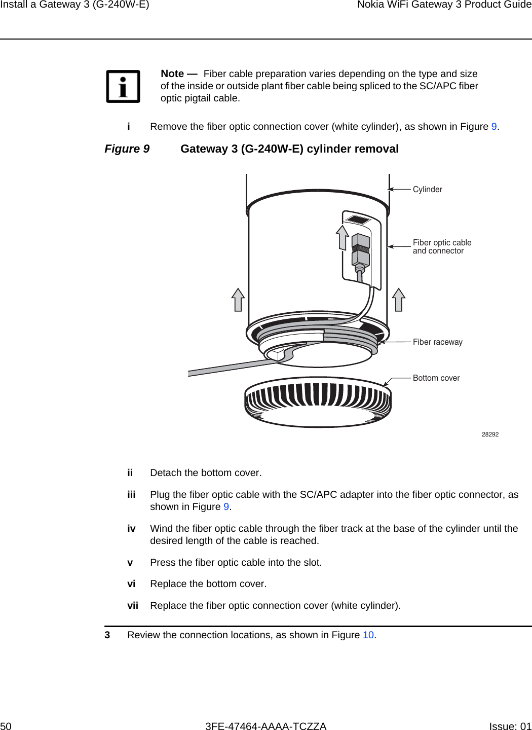
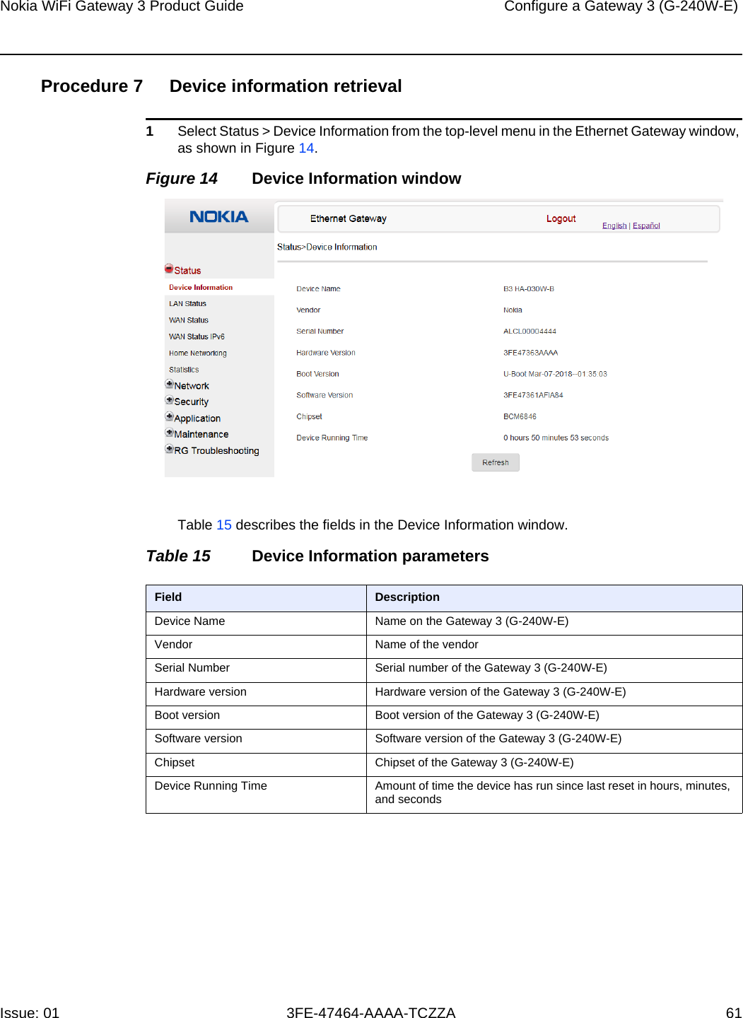
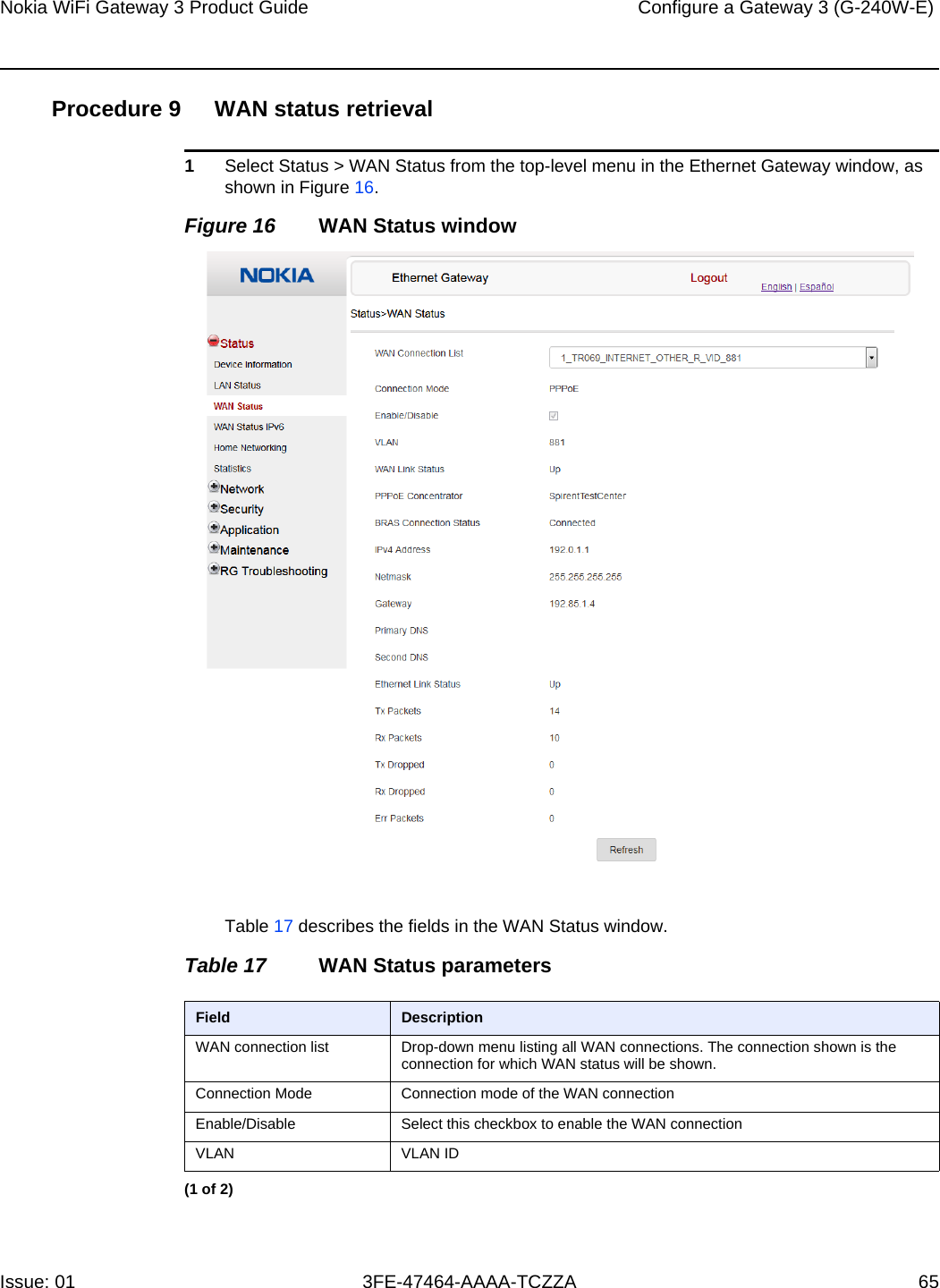
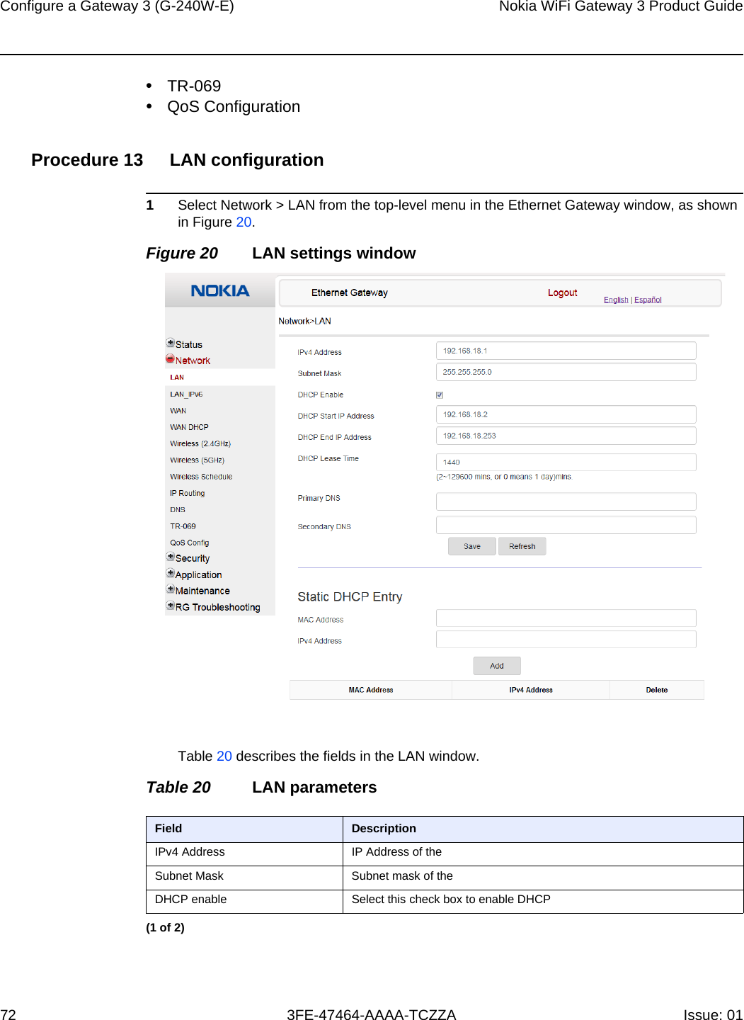
![Gateway 3 (G-240W-E) unit data sheet42Nokia WiFi Gateway 3 Product Guide3FE-47464-AAAA-TCZZA Issue: 01 5.5 Gateway 3 (G-240W-E) LEDsThe circular top of the Gateway 3 (G-240W-E) functions as a multi-color LED indicator. The LED color and pulse rate acts as a signal to the home user, which indicates the state of the Gateway 3 and the quality of its backhaul link.Table 9 provides LED descriptions for the Gateway 3 (G-240W-E).Table 9 Gateway 3 (G-240W-E) LED indications5.6 Gateway 3 (G-240W-E) detailed specificationsTable 10 lists the physical specifications for the Gateway 3 (G-240W-E).Table 10 Gateway 3 (G-240W-E) physical specificationsTable 11 lists the power consumption specifications for the Gateway 3 (G-240W-E).LED color LED behavior Router mode Bridge mode LED behavior descriptionOff Off ✓✓ Power off.Blue-Green Solid ✓Good backhaul connection to the Internet.Solid ✓Good backhaul connection. A link to the next node is available.Yellow Solid ✓Backhaul connection is successful but not optimal. A link to the next node is below standard.Slow pulsing ✓✓ Configuration mode. The unit is waiting to be configured.Red Solid ✓No connection to the Internet.Solid ✓Backhaul connection is not successful. A link to the next node is not operational.Fast pulsing ✓✓ Factory resetWhite Slow pulsing ✓✓ WPS enabled3 quick pulses ✓✓ WPS successfulSolid ✓✓ Powering onDescription SpecificationDiameter 94 mm (3.7 in.)Height 200 mm (78.7 in.)Weight [within ± 0.5 lb (0.23 kg)] 857g (1.89 lb)](https://usermanual.wiki/Nokia-Bell/G240WE/User-Guide-3934509-Page-42.png)
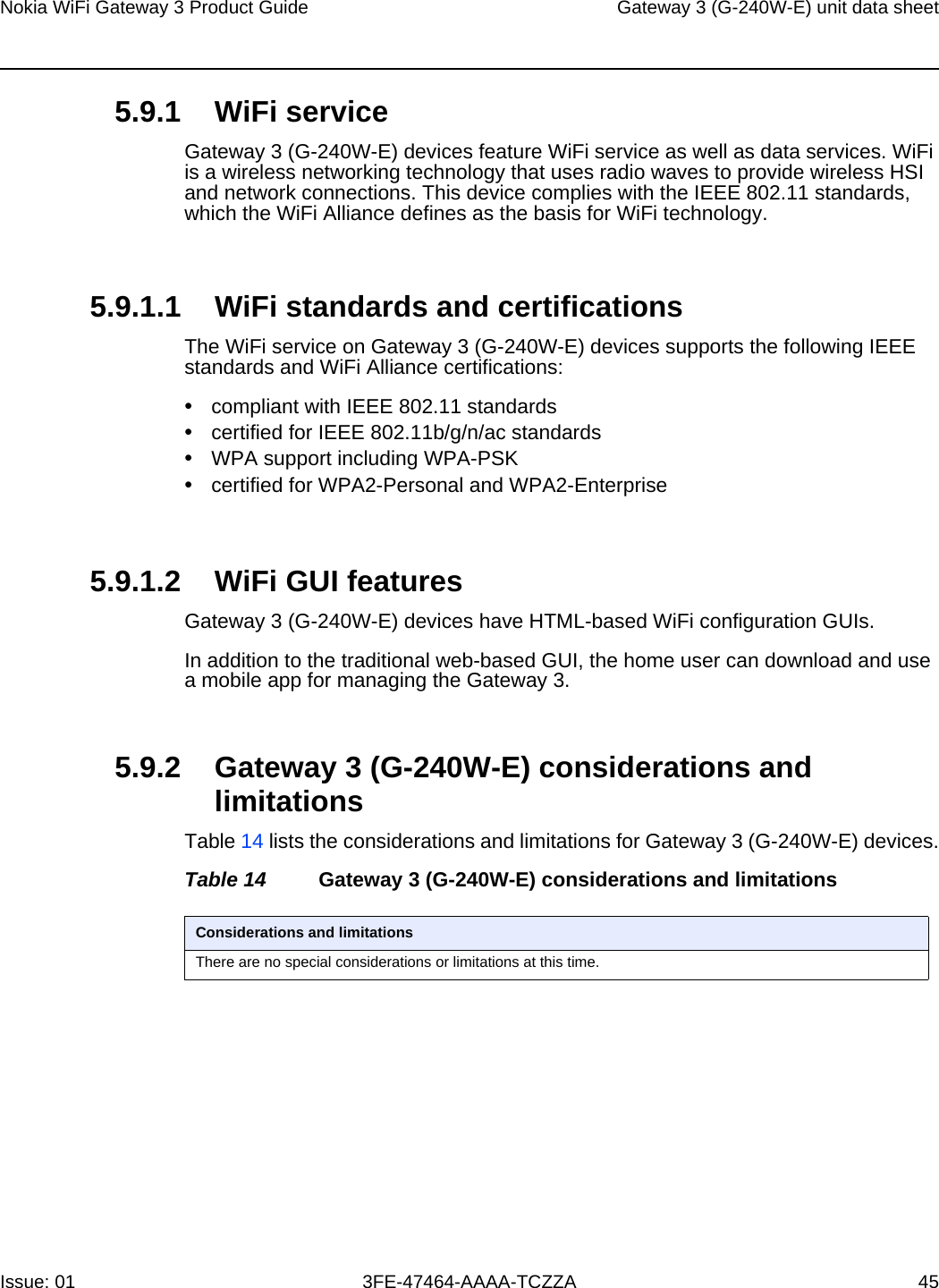


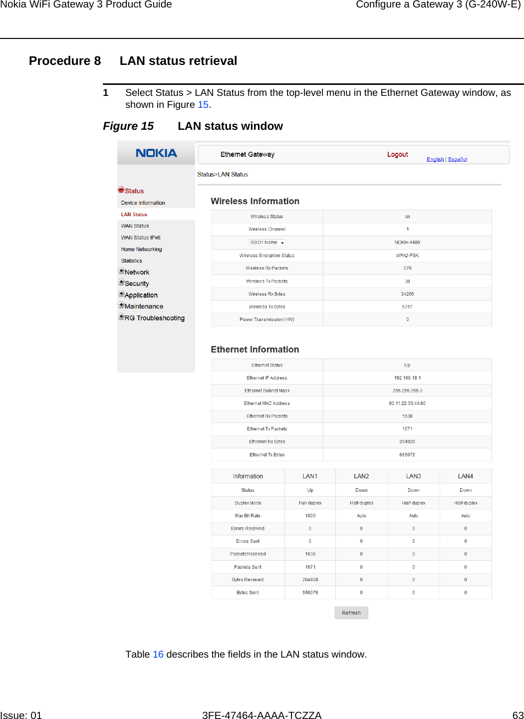
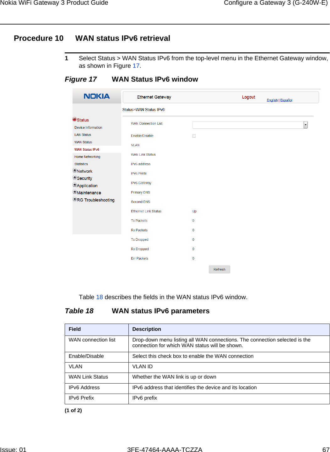
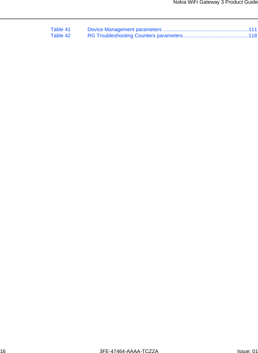
![Nokia WiFi Gateway 3 Product Guide Configure a Gateway 3 (G-240W-E) Issue: 01 3FE-47464-AAAA-TCZZA 109 Procedure 36 Password configurationA password must adhere to the following password rules:•the password may consist of uppercase letters, lowercase letters, digital numbers, and the following special characters ! # + , - / @ _ : = ]•the password length must be from 8 to 24 characters•the first character must be a digital number or a letter•the password must contain at least two types of characters: numbers, letters, or special characters•the same character must not appear more than 8 times in a rowWhen the password meets the password rules, the application displays the message “Your password has been changed successfully”.When the password does not meet the password rules, the application displays a message to indicate which password rule has not been followed, for example:•the password is too short•the password is too long•the first character cannot be a special character•there are not enough character classes1Select Maintenance > Password from the top-level menu in the GPON Home Gateway window, as shown in Figure 44.Figure 44 Password windowTable 40 describes the fields in the password window.](https://usermanual.wiki/Nokia-Bell/G240WE/User-Guide-3934509-Page-109.png)