Nokia Bell G241W-A GPON ONU User Manual
Alcatel-Lucent Shanghai Bell Co. Ltd. GPON ONU Users Manual
UserManual.wiki
>
Nokia Bell
>
G241W A User Manual
Users Manual
Navigation menu
Upload a User Manual
Namespaces
Wiki Guide
HTML
PDF
Info
Views
User Manual
Discussion / Help
Navigation
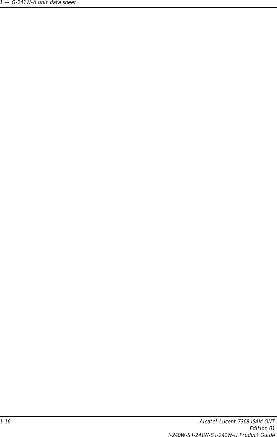
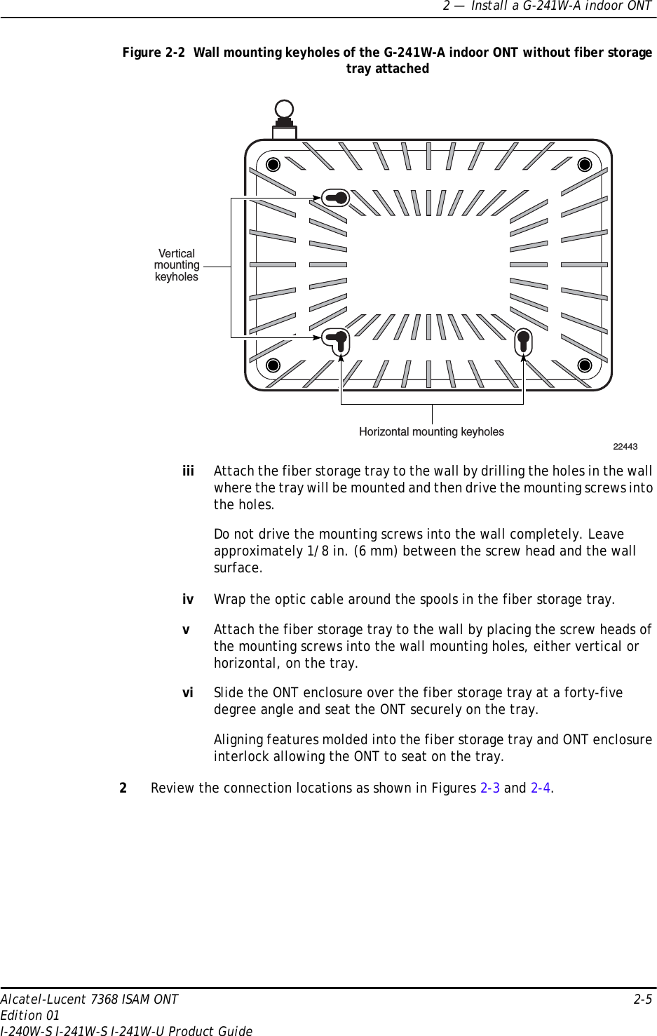
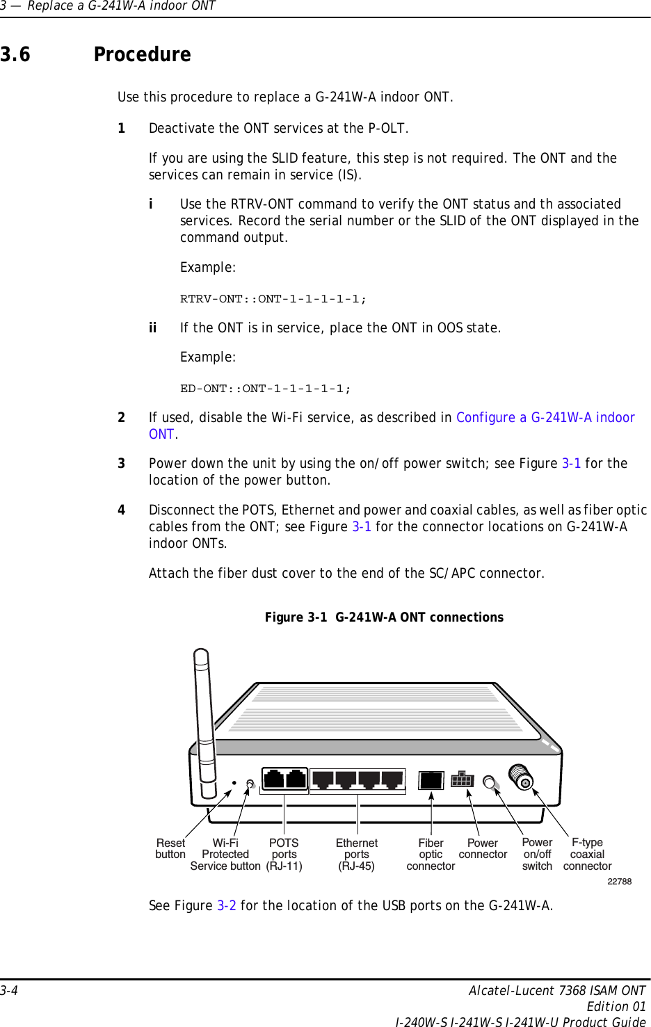
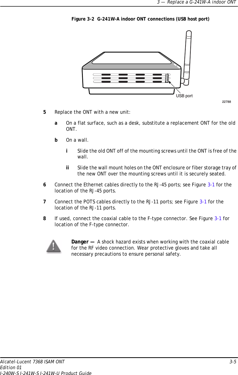
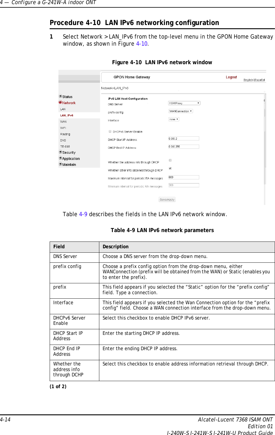
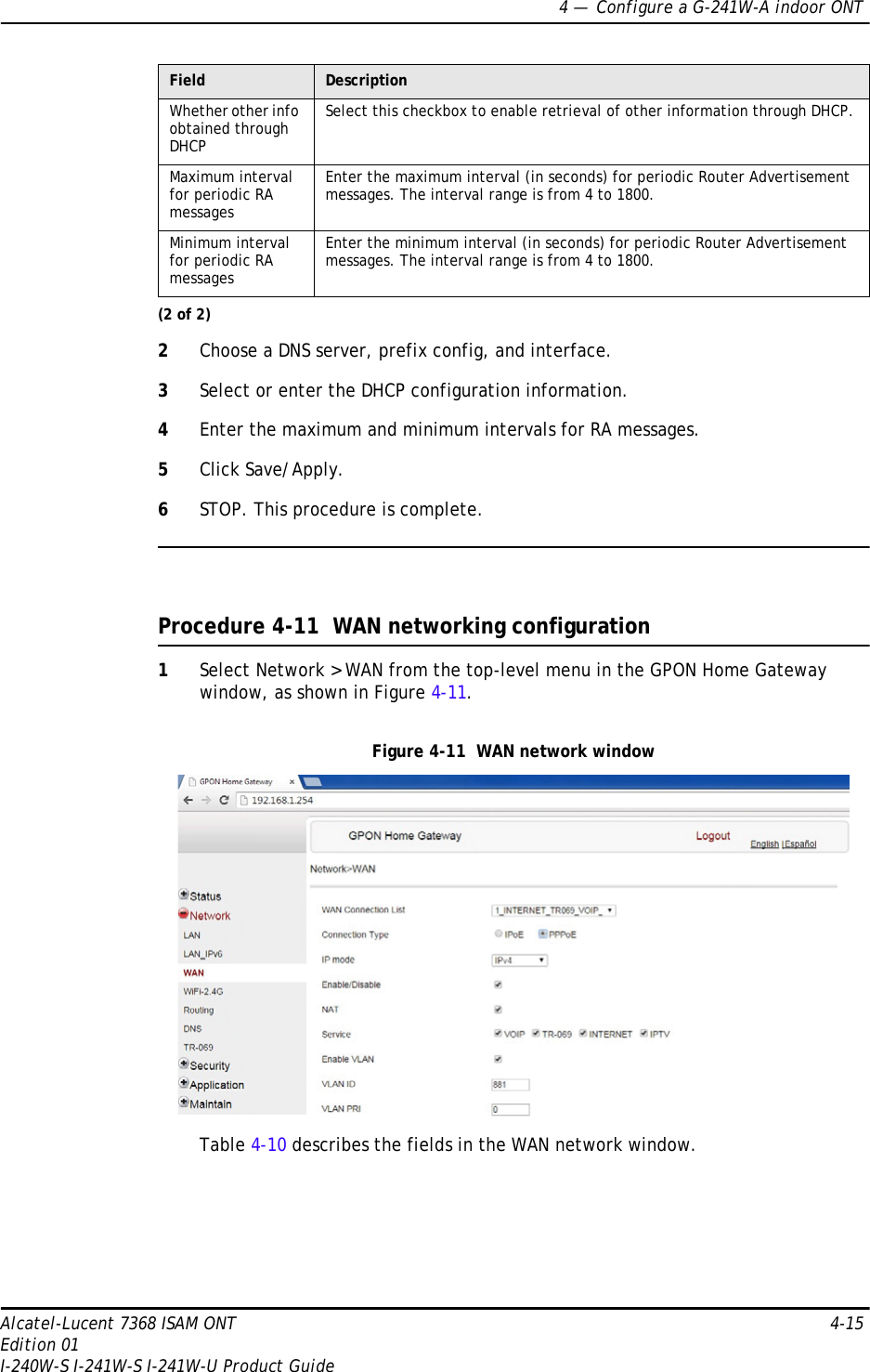
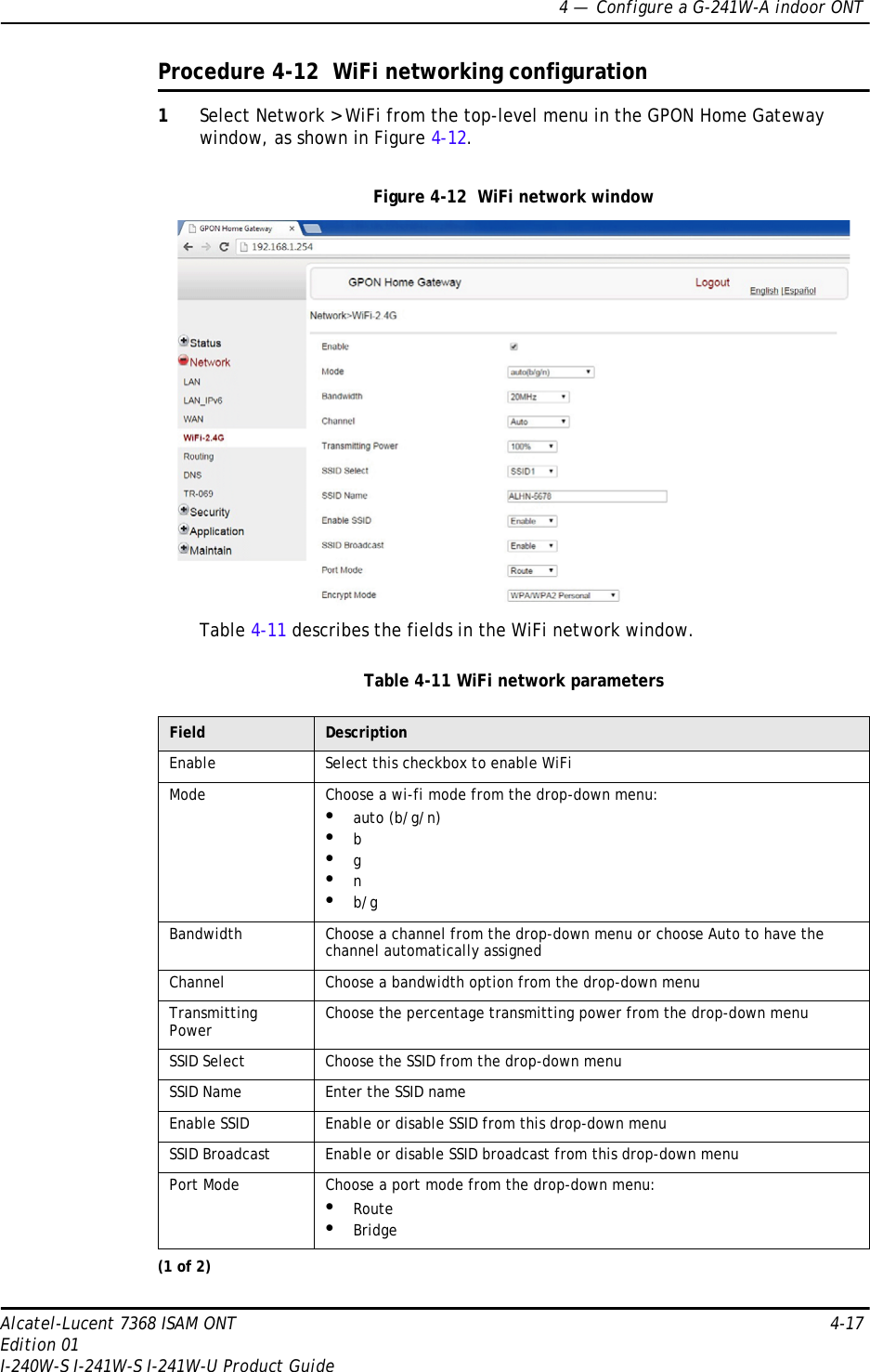
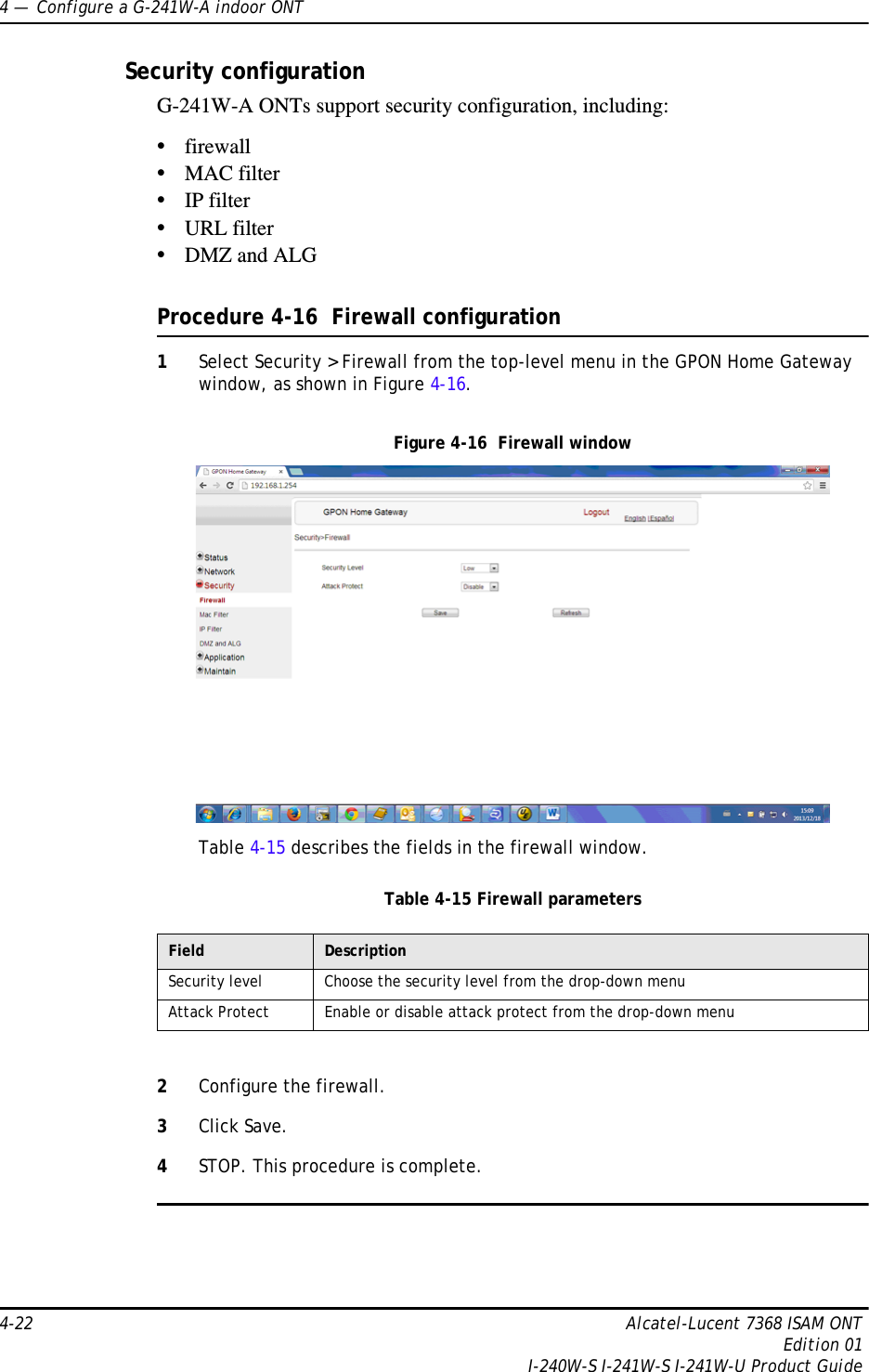
![1 — G-241W-A unit data sheet1-8 Alcatel-Lucent 7368 ISAM ONTEdition 01I-240W-S I-241W-S I-241W-U Product Guide1.6 G-241W-A detailed specificationsTable 1-6 lists the physical specifications for G-241W-A indoor ONTs.Table 1-6 G-241W-A indoor ONT physical specificationsTable 1-7 lists the power consumption specifications for G-241W-A indoor ONTs.LAN 1 to 4 Green solidGreen flashingOffEthernet is linkedLAN activity is present (in either direction)ONT power off or Ethernet not connectedTEL 1 to 2 Green solidGreen flashingOffOff hookCall in or talkingOn hookVOIP Green solidOff VOIP service is OKVOIP service is not OKWPS Green solidGreen flashingOffWireless LAN link is upWireless LAN link activityWireless LAN link down or no link connectedWLAN Green solidGreen flashingOffWireless enabledTraffic on wireless interfaceWireless is down or no link connectedUSB Green solidGreen flashingOffAt least one USB device is connectedTraffic activity on at least on USB deviceNo USB device connectedINTERNET Green solid Green flashingOffHSI WAN is connected: a) the device has an IP address assigned from IPCP, DHCP, or static, and no traffic has been detected; b) the session is dropped due to idle timeout but the PON link is still present.PPPoE or DHCP connection in progressHSI WAN is not connected: a) there is no physical interface connection; b) the device is in bridged mode without an assigned IP address; c) the session has been dropped for reasons other than idle timeout.VIDEO Green Red -6 to 0 dBmLess than -6 dBmIndicator LED color and behavior LED behavior description(2 of 2)Description Specification With fiber trayLength 8.9 in. (22.5 cm) 8.9 in. (22.5 cm)Width 6.5 in. (16.6 cm) 6.5 in. (16.6 cm)Height 1.65 in. (4.2 cm) 2.0 in. (5.2 cm)Weight including [within ± 0.5 lb (0.23 kg)] 1.12 lb (510 g) 1.3 lb (590 g)](https://usermanual.wiki/Nokia-Bell/G241W-A/User-Guide-2688980-Page-8.png)