Nokia Bell G241W-A GPON ONU User Manual
Alcatel-Lucent Shanghai Bell Co. Ltd. GPON ONU Users Manual
Users Manual

Alcatel-Lucent 7368 ISAM ONT 1-1
Edition 01
I-240W-S I-241W-S I-241W-U Product Guide
1 — G-241W-A unit data sheet
1.1 G-241W-A part numbers and identification 1-2
1.2 G-241W-A general description 1-3
1.3 G-241W-A software and installation feature support 1-4
1.4 G-241W-A interfaces and interface capacity 1-4
1.5 G-241W-A LEDs 1-6
1.6 G-241W-A detailed specifications 1-8
1.7 G-241W-A GEM ports and T-CONTs 1-9
1.8 G-241W-A performance monitoring statistics 1-9
1.9 G-241W-A functional blocks 1-11
1.10 G-241W-A standards compliance 1-14
1.11 G-241W-A special considerations 1-14

1 — G-241W-A unit data sheet
1-2 Alcatel-Lucent 7368 ISAM ONT
Edition 01
I-240W-S I-241W-S I-241W-U Product Guide
1.1 G-241W-A part numbers and identification
Table 1-1 provides part numbers and identification information for G-241W-A
indoor ONTs.
Table 1-1 G-241W-A indoor ONT part numbers and identification
The G-241W-A ONT uses a fiber storage tray that can be ordered separately. The
part number for the fiber tray is 3FE 71441 AA.
Table 1-2 lists ONT to UPS or power adapter support mapping, including the
specifications and standards tested to.
Mnemonic Ordering kit
part number Provisioning
part number Description CLEI CPR ECI/
Bar
code
G-241W-A 3FE 56867 AA
customer-
specific
3FE 56977 AA Package D 2 POTS ports, 4 Gig-E
10/100/1000 Base-T interfaces, 1 RF
video connector, and 1 Wi-Fi radio
on/off switch. Includes ac/dc power
cord with European (EU) variant plug.
———
3FE 56867 BA 3FE 56977 BA Package D 2 POTS ports, 4 Gig-E
10/100/1000 Base-T interfaces, 1 RF
video connector, and 1 Wi-Fi radio
on/off switch. Includes ac/dc power
cord with European (EU) variant plug.
———
3FE 56867 BB
customer-
specific
Package D 2 POTS ports, 4 Gig-E
10/100/1000 Base-T interfaces, 1 RF
video connector, and 1 Wi-Fi radio
on/off switch. Includes ac/dc power
cord with European (EU) variant plug.
———
3FE 56867 CA Package D 2 POTS ports, 4 Gig-E
10/100/1000 Base-T interfaces, 1 RF
video connector, and 1 Wi-Fi radio
on/off switch. Includes ac/dc power
cord with United Kingdom (UK) variant
plug.
———
3FE 56867 DA Package D 2 POTS ports, 4 Gig-E
10/100/1000 Base-T interfaces, 1 RF
video connector, and 1 Wi-Fi radio
on/off switch. Includes ac/dc power
cord with United States (US) variant
plug.
———
3FE 56867 DB Package D 2 POTS ports, 4 Gig-E
10/100/1000 Base-T interfaces, 1 RF
video connector, and 1 Wi-Fi radio
on/off switch. Includes ac/dc power
cord with United States (US) variant
plug.
Also includes POTS LED and Molex port
———

1 — G-241W-A unit data sheet
Alcatel-Lucent 7368 ISAM ONT 1-3
Edition 01
I-240W-S I-241W-S I-241W-U Product Guide
Table 1-2 ONT to UPS or power adapter compatibility support
1.2 G-241W-A general description
G-241W-A indoor ONTs provide the subscriber interface for the network by
terminating the PON interface and converting it to user interfaces that directly
connect to subscriber devices. The ONT is compatible with all existing subscriber
equipment, including analog phones with both tone and rotary dial capabilities,
cordless phones, modems, fax machines, and caller ID boxes (Type I, Type II, and
Type III).
G-241W-A indoor ONTs provide the following functions:
•four configurable 10/100/1000BASE-T Ethernet interfaces using RJ-45 ports
•two POTS interfaces using RJ-11 ports
•single mode fiber (SC/APC connector)
•one coaxial RF video connector
•two USB ports
•detachable 3dB/5dB antenna
•IEEE 802.11 b/g/n Wi-Fi interface to enable wireless access
•adjustable Wi-Fi power
•fully G.984 series GPON standard compliant
•G984.5 standard compliant
•compliance with FCC part 15 Class B, CE
•VPN pass-through for PPTP, L2TP, and IPsec
•mapping VLAN to each Ethernet port
•Layer 2 bridging
•NAT/NAPT/port forwarding/DMZ
•IGMP v2/v3
•IPv4 and IPv6
•QoS: CoS or DSCP
•RSSI support
•manual addition of DDNS server
Power/UPS model Power UPS and cabling part
number information Customer category or
country compliance tested
for
Notes
G-241W-A GPON indoor ONTs
CyberPower
CSN27U12V3
Grounded
(1) 12 V/27 W UPS part number:
3MV00213AA (DC power cord
included)
(2) AC power cord, 1AB38334xxxx:
•0007 — Australia, New Zealand
•0008 — Europe
•0009 — United Kingdom,
Ireland
•0010 — ANSI
Common European Union
countries
ANSI municipality United
States and Canada
Battery not included.
Compliant battery models:
•BB Battery BP7.2-12
•GS Battery PE 12V7.2
(ANSI GS Battery ALU
part number
1AF17581AC)

1 — G-241W-A unit data sheet
1-4 Alcatel-Lucent 7368 ISAM ONT
Edition 01
I-240W-S I-241W-S I-241W-U Product Guide
TR-069 support for reading optical parameters
The ONT supports the reading of optical parameters via TR-069:
•laser bias current
•voltage
•temperature
•received signal levels
•lower thresholds
These are the same optical parameters supported in the GUI. For more information,
see the chapter “Configure a G-241W-A indoor ONT”.
1.3 G-241W-A software and installation feature support
For information on installing or replacing a G-241W-A, see:
•Install a G-241W-A indoor ONT
•Replace a G-241W-A indoor ONT
For information on the following topics, see the 7368 ISAM ONT Product Overview
Guide:
•ONT and MDU general descriptions of features and functions
•Ethernet interface specifications
•POTS interface specifications
•RF video interface specifications for video overlay
•RSSI specifications
•Wi-Fi specifications
•ONT optical budget
•SLID entry via Ethernet port
•Web-based ONT configuration
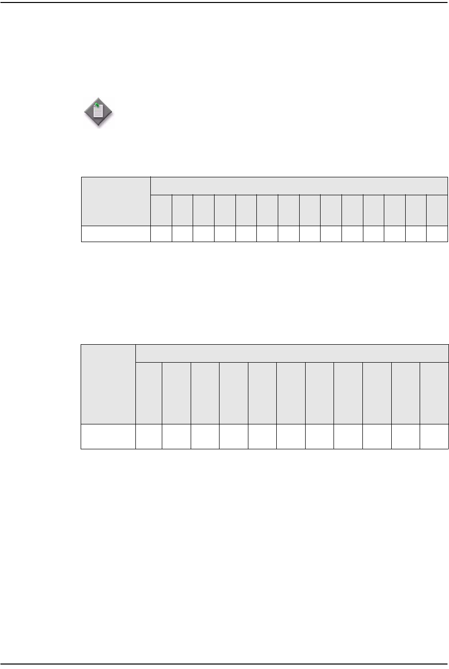
1.4 G-241W-A interfaces and interface capacity
Table 1-3 describes the supported interfaces and interface capacity for G-241W-A
indoor ONTs.
Table 1-3 G-241W-A indoor ONT interface connection capacity
ONT type
and model Maximum capacity
POTS 10/
100
BASE-
T
10/
100/
1000
BASE-
T
RF
video
(CATV)
MoCA VDSL2 E1/T1 Local
craft GPON
SC/
APC
HPNA USB
G-241W-A (1) 2—41 ————1—2
1 — G-241W-A unit data sheet
Alcatel-Lucent 7368 ISAM ONT 1-5
Edition 01
I-240W-S I-241W-S I-241W-U Product Guide
Note
(1) G-241W-A ONTs provide Wi-Fi service without a physical connection.
G-241W-A connections and components
G-241W-A indoor ONTs are intended for indoor deployment and can be installed
vertically, horizontally, or attached to a wall.
Other features of these indoor ONTs include
•an ON/OFF power switch for manual shut down
•a reset button
•an external multi-directional antennae
•Wi-Fi service that is enabled and disabled by Web GUI or TR-064/TR-069
•a Wi-Fi Protected Setup button
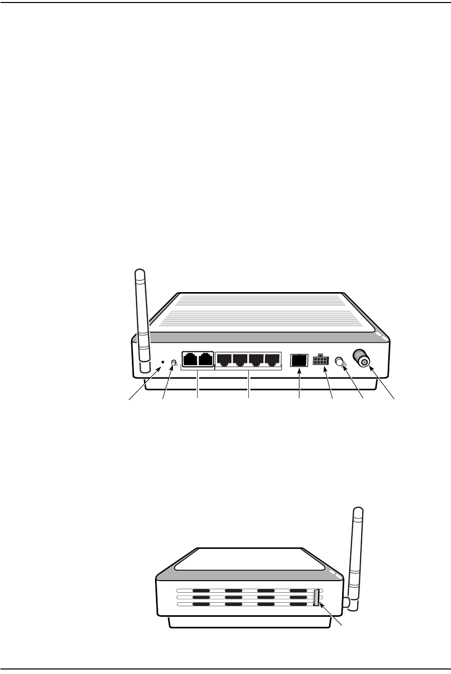
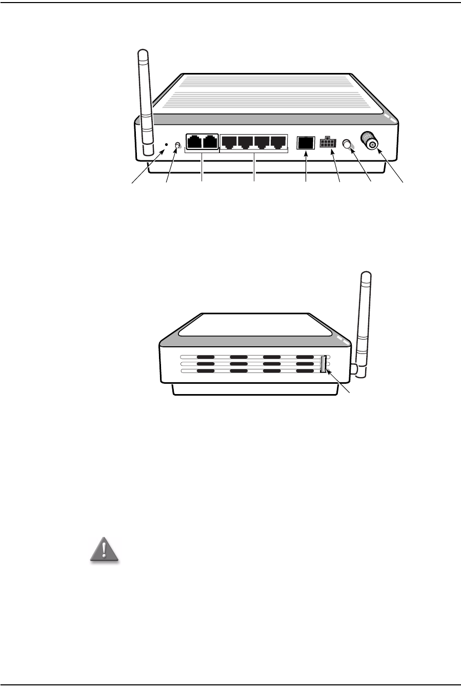
Figure 1-1 shows the physical connections for G-241W-A indoor ONTs.
Figure 1-1 G-241W-A indoor ONT physical connections
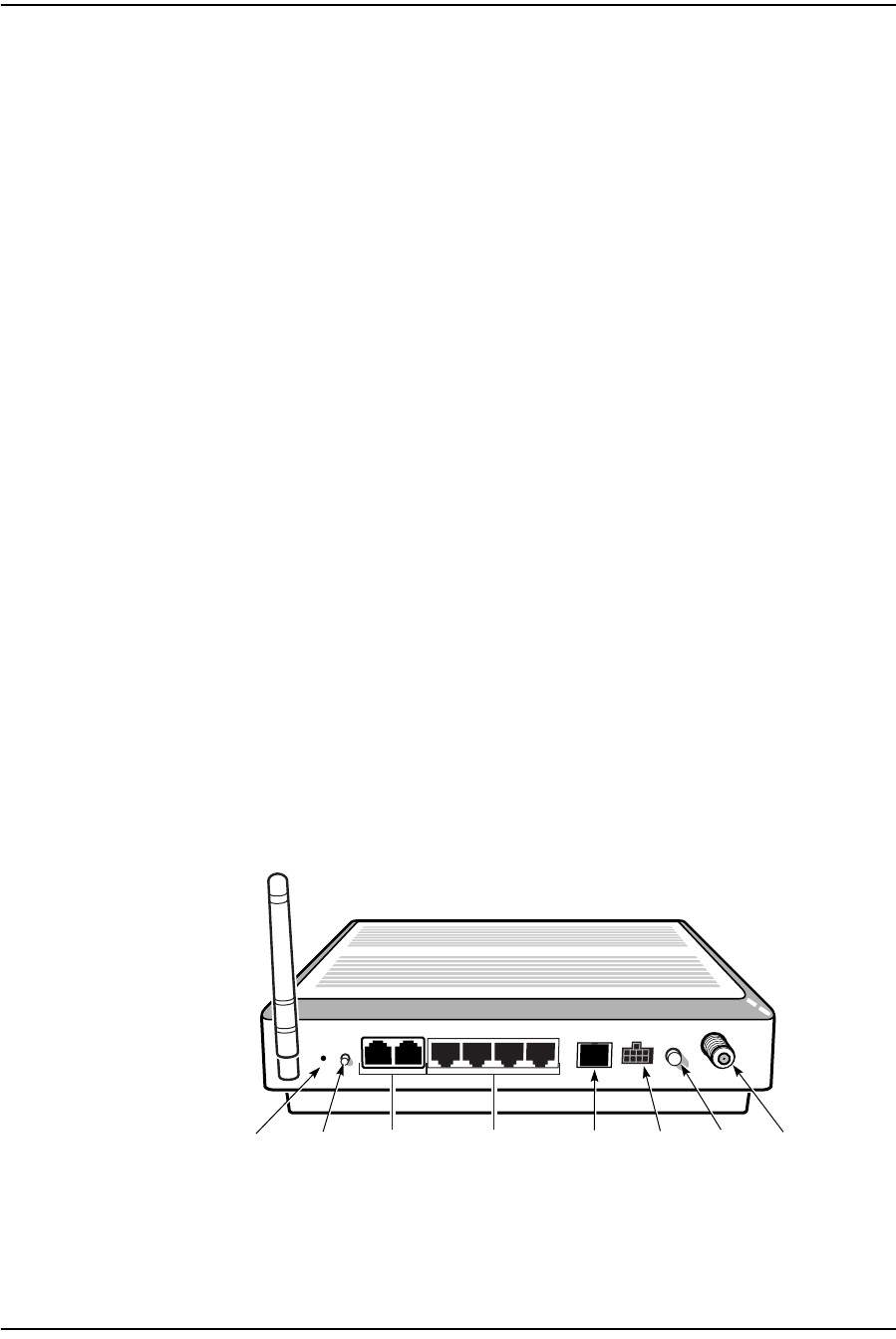
Figure 1-2 shows the location of the USB ports on the G-241W-A indoor ONTs.
Figure 1-2 G-241W-A indoor ONT physical connections (USB host ports)
Wi-Fi
Protected
Service button
Reset
button
POTS
ports
(RJ-11)
Ethernet
ports
(RJ-45)
Fiber
optic
connector
Power
connector
Power
on/off
switch
F-type
coaxial
connector
22788
USB port
22788

1 — G-241W-A unit data sheet
1-6 Alcatel-Lucent 7368 ISAM ONT
Edition 01
I-240W-S I-241W-S I-241W-U Product Guide
Table 1-4 describes the physical connections for G-241W-A indoor ONTs.
Table 1-4 G-241W-A indoor ONT physical connections
Note
(1) The primary path for the earth ground for these ONTs is provided by the 12V Return signal in the
power connector.
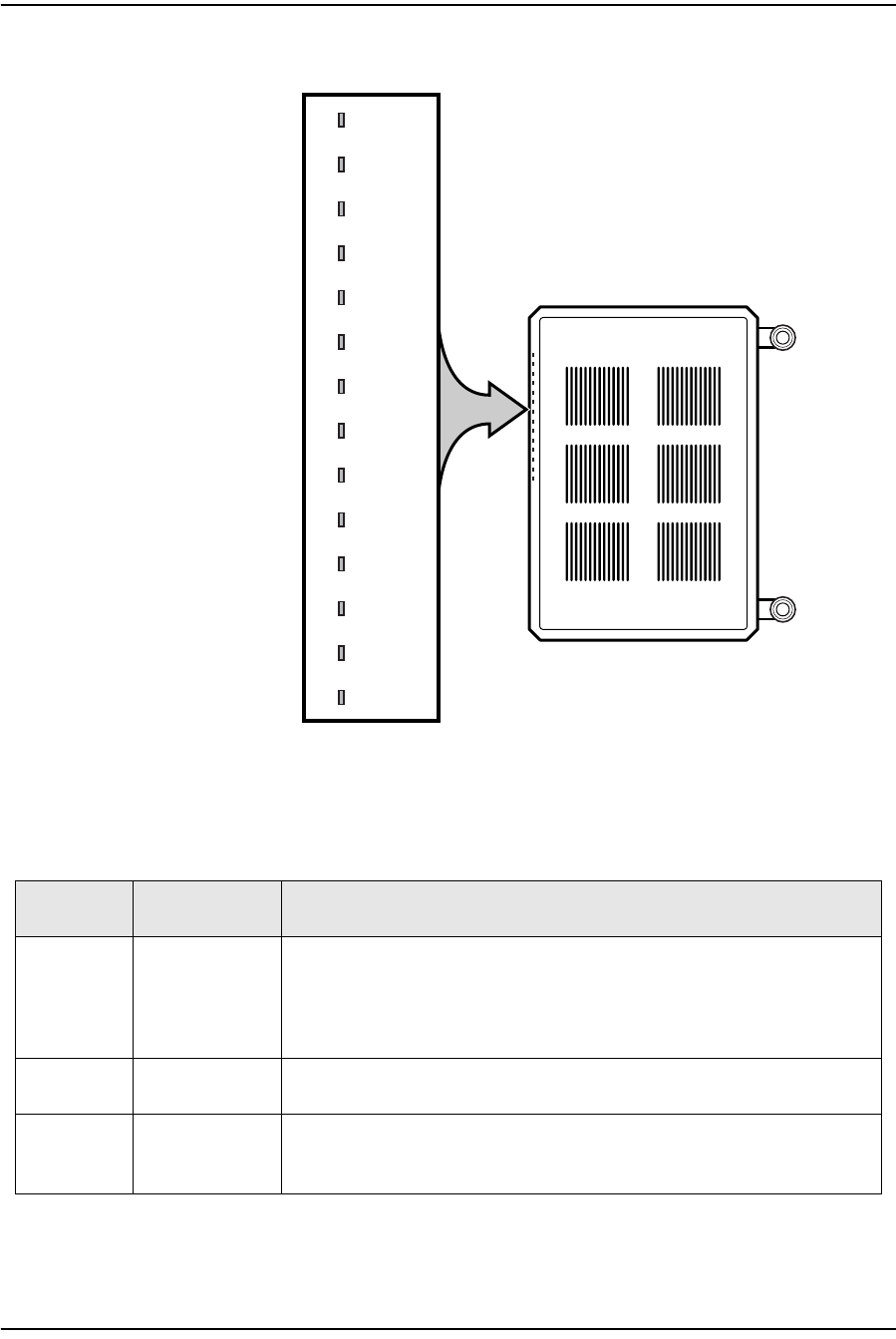
1.5 G-241W-A LEDs
Figure 1-3 shows the G-241W-A indoor ONT LEDs.
Connection (1) Description
Ethernet ports This connection is provided through Ethernet RJ-45 cables. Up to four
10/100/1000 Base-T Ethernet interfaces are supported.The Ethernet
ports can support both data and in-band video services on all four
interfaces.
POTS This connection is provided through RJ-11 ports. Up to two POTS
connections are supported.The POTS ports support voice services.
WPS button The Wi-Fi Protected Setup switch is labeled WPS. This button enables
and disables the WPS mode.
RF video coaxial This connection is provided through a F-Type coaxial connector.
Power This connection is provided through the power connector. A power
cable fitted with a Molex connector is used to make the connection.
Fiber optic This connection is provided through a GPON SC/APC fiber optic
connector.
USB ports This connection is provided by two USB host ports, compliant to USB
2.0.
Cables with A-type connectors are used to connect to the USB ports.
1 — G-241W-A unit data sheet
Alcatel-Lucent 7368 ISAM ONT 1-7
Edition 01
I-240W-S I-241W-S I-241W-U Product Guide
Figure 1-3 G-241W-A indoor ONT LEDs
Table 1-5 provides LED descriptions for G-241W-A indoor ONTs.
Table 1-5 G-241W-A indoor ONT LEDs
POWER
LINK
AUTH
LAN1
LAN2
LAN3
LAN4
TEL1
TEL2
VoI P
WPS
WLAN
USB
INTERNET
POWER
LINK
AUTH
LAN1
LAN2
LAN3
LAN4
TEL1
TEL2
VoIP
WPS
WLAN
USB
INTERNET
24510
Indicator LED color and
behavior LED behavior description
Power Green solid
Red solid
Off
Power on
Light failed on startup (for example corrupt flash), or self test failed on startup,
or self test failed during regular operation or when executed over OMCI
The LED is red by default until the software is running properly and turns it green
Power off
Link Green solid
Off GPON link between ONT and OLT is operating normally
GPON link is down or no link connected
Auth Green solid
Green flashing
Off
ONT is authorized
In process of ranging or synchronizing on OMCI
ONT is not authorized
(1 of 2)

1 — G-241W-A unit data sheet
1-8 Alcatel-Lucent 7368 ISAM ONT
Edition 01
I-240W-S I-241W-S I-241W-U Product Guide
1.6 G-241W-A detailed specifications
Table 1-6 lists the physical specifications for G-241W-A indoor ONTs.
Table 1-6 G-241W-A indoor ONT physical specifications
Table 1-7 lists the power consumption specifications for G-241W-A indoor ONTs.
LAN 1 to 4 Green solid
Green flashing
Off
Ethernet is linked
LAN activity is present (in either direction)
ONT power off or Ethernet not connected
TEL 1 to 2 Green solid
Green flashing
Off
Off hook
Call in or talking
On hook
VOIP Green solid
Off VOIP service is OK
VOIP service is not OK
WPS Green solid
Green flashing
Off
Wireless LAN link is up
Wireless LAN link activity
Wireless LAN link down or no link connected
WLAN Green solid
Green flashing
Off
Wireless enabled
Traffic on wireless interface
Wireless is down or no link connected
USB Green solid
Green flashing
Off
At least one USB device is connected
Traffic activity on at least on USB device
No USB device connected
INTERNET Green solid
Green flashing
Off
HSI WAN is connected: a) the device has an IP address assigned from IPCP, DHCP,
or static, and no traffic has been detected; b) the session is dropped due to idle
timeout but the PON link is still present.
PPPoE or DHCP connection in progress
HSI WAN is not connected: a) there is no physical interface connection; b) the
device is in bridged mode without an assigned IP address; c) the session has been
dropped for reasons other than idle timeout.
VIDEO Green
Red -6 to 0 dBm
Less than -6 dBm
Indicator LED color and
behavior LED behavior description
(2 of 2)
Description Specification With fiber tray
Length 8.9 in. (22.5 cm) 8.9 in. (22.5 cm)
Width 6.5 in. (16.6 cm) 6.5 in. (16.6 cm)
Height 1.65 in. (4.2 cm) 2.0 in. (5.2 cm)
Weight including [within ± 0.5 lb
(0.23 kg)] 1.12 lb (510 g) 1.3 lb (590 g)

1 — G-241W-A unit data sheet
Alcatel-Lucent 7368 ISAM ONT 1-9
Edition 01
I-240W-S I-241W-S I-241W-U Product Guide
Table 1-7 G-241W-A indoor ONT power consumption specifications
Table 1-8 lists the environmental specifications for G-241W-A indoor ONTs.
Table 1-8 G-241W-A indoor ONT environmental specifications
1.7 G-241W-A GEM ports and T-CONTs
Table 1-9 lists the maximum number of supported T-CONTs and GEM ports.
Table 1-9 G-241W-A indoor ONT capacity for GEM ports and T-CONTs
1.8 G-241W-A performance monitoring statistics
The following section identifies the supported performance monitoring statistics for
G-241W-A ONTs. A check mark indicates the statistic is supported on that ONT. An
empty cell indicates the statistic is not supported. A cell without a check mark
indicates that the counter is not applicable to that type of ONT. The following tables
are categorized by supported alarm types:
•Table 1-10 provides statistics for ONTENET type counters
•Table 1-11 provides statistics for ONTL2UNI type counters
Mnemonic Maximum power
(Not to exceed) Condition Minimum power Condition
G-241W-A 18 W 2 POTS off-hook, 4 Gig-E, 1 RF
video, Wi-Fi operational 6 W 2 POTS on-hook, other
interfaces/services not
provisioned
Mounting method Temperature range and humidity Altitude
Desk or wall
mounted Operating:
32°F to 113°F (0°C to 45°C) ambient
temperature
10% to 90% relative humidity, non-condensing
Contact your Alcatel-Lucent technical support
representative for more information
Storage:
68°F to 149°F (20°C to 65°C)
ONT or MDU Maximum Notes
GEM ports per indoor or
outdoor ONT 128 128 are present: 127 are available, 1 is
reserved for OMCI
T-CONTs per indoor or outdoor
ONT 8—
1 — G-241W-A unit data sheet
1-10 Alcatel-Lucent 7368 ISAM ONT
Edition 01
I-240W-S I-241W-S I-241W-U Product Guide
•Table 1-12 provides statistics for PONONTTC, PONONTMCTC,
PONONTTCHSI, PONONTTCCES, PONONTTCFLOW, and
PONONTTCVOIP type counters
•Table 1-13 provides statistics for PONONTTC aggregate type counters
Table 1-10 G-241W-A ONT ONTENET performance monitoring statistics
Note
(1) A 5 second polling window limitation exists on the ONT, therefore the margin of error for each
15-min window is 5 seconds
Table 1-11 G-241W-A ONT ONTL2UNI performance monitoring statistics
Note
(1) A 5 second polling window limitation exists on the ONT, therefore the margin of error for each
15-min window is 5 seconds
Note — If you have trouble accessing G-241W-A ONTs performance
monitoring statistics using TL1, please contact your Alcatel-Lucent
support representative for more information about how to access and
retrieve performance monitoring type counters.
ONT ONTENET statistics
FCSE
EC
LC
RBO
SCF
MCF
DT
IMTE
CSE
AE
IMRE
FTL
TBO
SQE
G-241W-A (1) ✓✓✓✓✓✓✓✓✓✓✓✓✓✓
ONT ONTL2UNI statistics
FRAMES
BYTES
MCFRAMES
DSDRPDFRMS
USDRPDFRMS
USFRAMES
DSFRAMES
USBYTES
DSBYTES
USMCFRAMES
DSMCFRAMES
G-241W-A
(1) ✓✓✓✓✓✓

1 — G-241W-A unit data sheet
Alcatel-Lucent 7368 ISAM ONT 1-11
Edition 01
I-240W-S I-241W-S I-241W-U Product Guide
Table 1-12 G-241W-A ONT PONONTTC, PONONTMCTC, PONONTTCHSI, PONONTTCCES,
PONONTTCFLOW, PONONTTCVOIP performance monitoring statistics
Notes
(1) A 5 second polling window limitation exists on the ONT, therefore the margin of error for each
15-min window is 5 seconds
(2) TC layer OAM performance monitoring is not supported on the OLT R04.00.10 therefore LOSTFRAGS
and TXFRAG counters are not supported on indoor ONTs.
(3) The LOSTFRAGS statistic is supported in the downstream direction only.
Table 1-13 G-241W-A ONT PONONTTC aggregate performance monitoring statistics
Notes
(1) The lost GEM fragment counter supports downstream direction only. Upstream direction is not
supported.
(2) A 5 second polling window limitation exists on the ONT, therefore the margin of error for each
15-min window is 5 seconds
1.9 G-241W-A functional blocks
Table 1-14 describes the supported interfaces for G-241W-A indoor ONTs.
ONT PONONTTC, PONONTMCTC, PONONTTCHSI, PONONTTCCES,
PONONTTCFLOW, PONONTTCVOIP statistics
TXBLOCKS
TXFRAGS
RXBLOCKS
RXFRAGS
LOSTFRAGS
BADGEMHDRS
G-241W-A (1) (2) (3) ✓✓✓✓✓✓
ONT PONONTTC (aggregate) statistics
TXBLOCKS
TXFRAGS
RXBLOCKS
RXFRAGS
LOSTFRAGS(1)
BADGEMHDRS
G-241W-A (2) ✓✓✓✓✓✓
1 — G-241W-A unit data sheet
1-12 Alcatel-Lucent 7368 ISAM ONT
Edition 01
I-240W-S I-241W-S I-241W-U Product Guide
Table 1-14 G-241W-A indoor ONT interfaces
G-241W-A indoor ONTs are single-residence ONTs that support Wireless (Wi-Fi)
service. Wi-Fi service on these ONTs are compliant with the IEEE 802.11 standard
and enabled or disabled using a radio on/off switch.
In addition to the Wi-Fi service, these ONTs transmit Ethernet packets to four RJ-45
Ethernet ports, and voice traffic to two RJ-11 POTS ports. These ONTs have two
USB ports also.
The ONTs also support RF video traffic on one F-type coaxial connector. The ONTs
feature fiber optic and power connectors.
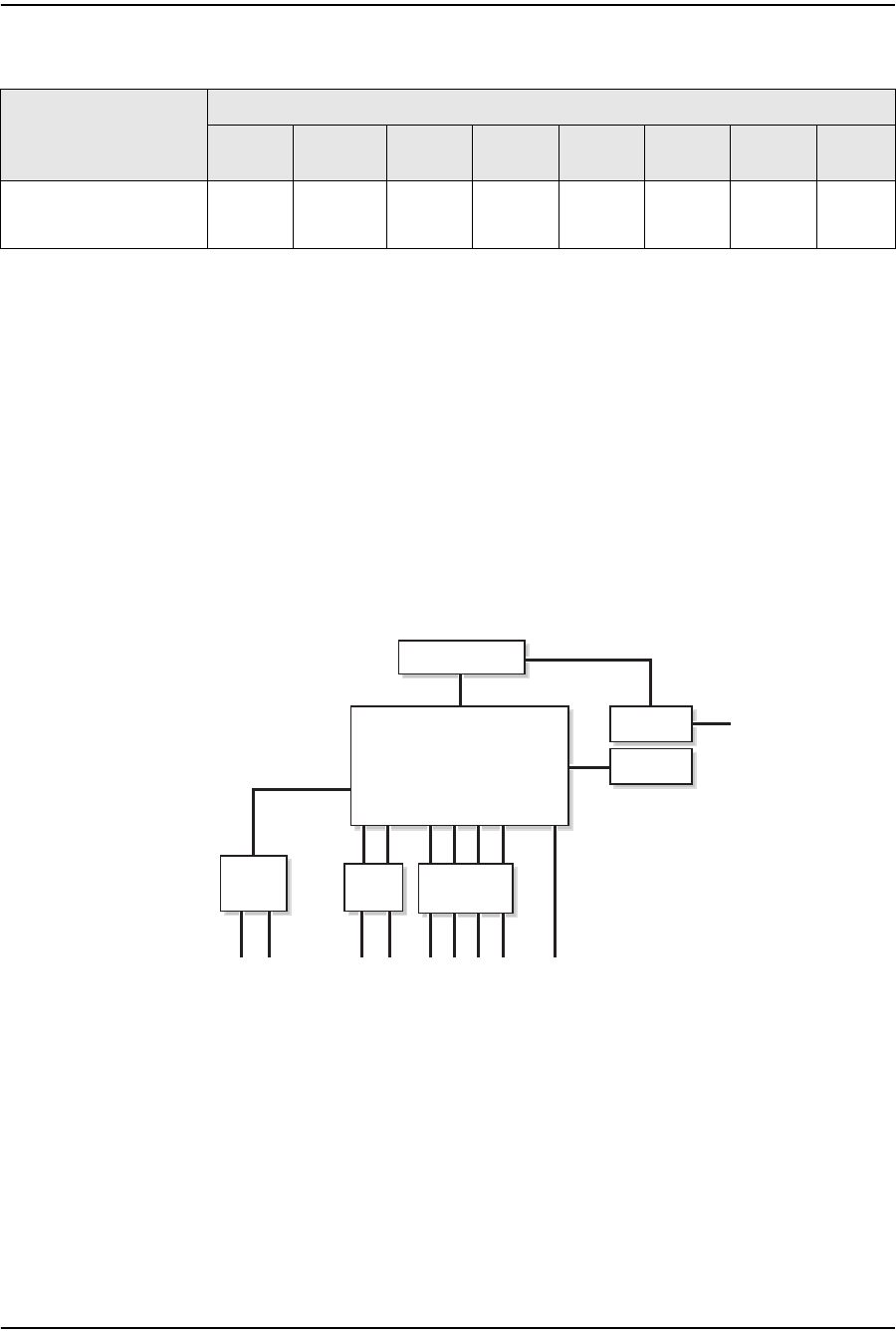
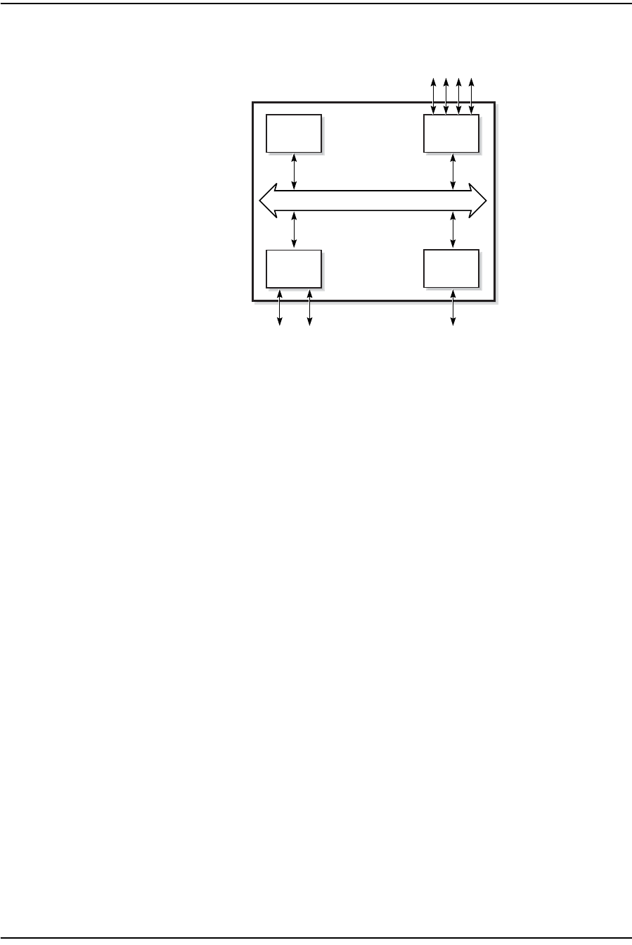
Figure 1-4 shows functional blocks for G-241W-A indoor ONTs.
Figure 1-4 Single-residence Wi-Fi ONT with Gigabit Ethernet and POTS and with RF video
ONT SoC technology serves as the main hardware block for these ONTs; see
Figure 1-5.
ONT category
description Interface capacity
POTS
ports Ethernet
ports VDSL2 MoCA RF
Video HPNA Wi-Fi USB
Single-residence Wi-Fi
ONTs with Gig-E ONTs,
POTS, with RF video
24——1—11
Internal
USB host
PWR
F-type connector
4xRJ452xRJ11
22570
Triplexer
GE PHY
switch
RF or
HPNA filter
RESET
GPON
SOC
POTS
2xUSB
External
USB
Host
1 — G-241W-A unit data sheet
Alcatel-Lucent 7368 ISAM ONT 1-13
Edition 01
I-240W-S I-241W-S I-241W-U Product Guide
Figure 1-5 G-241W-A ONT hardware block
ONT SoC technology consists of five key elements:
•GPON MAC
The Gigabit Passive Optical Network Media Access Control (GPON MAC)
element on the SoC terminates the GPON interface using an optical diplexer. This
interface supports GPON as described in G.984.3 (GPON TC Layer) ITU
specification.
•Ethernet MAC
The SoC provides up to four GE MACs.
•DSP interface
The Digital Signal Processor (DSP) provides voice processing for 2 POTS lines
with the 3-way calling. The DSP has a dedicated 64 kbyte instruction cache and
shares a 32 kbyte data cache with the Control Processor.
•Control Processor
The Control Processor features an integral memory management unit that
supports a dedicated 64 kbyte instruction cache and shares a single 32 kbyte data
cache with the DSP. The Control Processor and DSP also include a single channel
Data Management Application (DMA) controller with a 4 kbyte read ahead
low-latency Dynamic Random Access Memory (DRAM) access port. The
processors typically run at 400 MHz.
•Switch matrix
The Switch matrix provides an integrated data channel between the four GE
MACs, the GPON MAC, the DSP, the control processor, and the other integrated
elements such as flash memory, DRAM, and the local bus controller.
These ONTs can also interact with additional hardware components to support
functionality not provided by the SoC technology.
Control
processor
Ethernet
MACs
Ethernet ports GPON
POTS ports
DSP
GPON
MAC
SoC
19421
SoC Bridge

1 — G-241W-A unit data sheet
1-14 Alcatel-Lucent 7368 ISAM ONT
Edition 01
I-240W-S I-241W-S I-241W-U Product Guide
1.10 G-241W-A standards compliance
G-241W-A indoor ONTs are compliant with the following standards:
•802.11b support for maximum transmit power (EIRP) equal to or greater than 200
mW (23.01 dBm)
•802.11g support for maximum transmit power (EIRP) equal to or greater than 100
mW (20 dBm)
•802.11n support for wireless LAN interface
•G.711a/u, G-729 CODEC
•G.984 support GPON interface (framing)
•G.984.2 support for Amd1, class B+
•G984.5 support for optical and other transport network infrastructures
•Wi-FI: WEP/WPA/WPA2, WPA-PSK/WPA2-PSK
1.11 G-241W-A special considerations
G-241W-A are package D ONTs.
G-241W-A indoor ONT considerations and limitations
Table 1-15 lists the considerations and limitations for Package D G-241W-A ONTs.
Table 1-15 G-241W-A ONT considerations and limitations
Upgrade considerations and limitations
Existing ONTs that use 7342 ISAM FTTU releases older than R04.06.xx and
R04.07.xx must be upgraded to use R04.00.10 software while assigned to a PON ID
value smaller than 64. For this purpose, if split ratios larger than 1:64 are being
deployed, you may choose to set aside the first PON ID as a staging point.
Considerations and limitations
The ONT pads packets to 104 as SoC limitation
Due to a Layer 3 packet processing limitation, the ONT can handle up to 220Mb/s (@ up to 72 bytes
for Ethernet Frame sizes. Rates that exceed 220Mb/s with Ethernet frame sizes of less than 72 bytes
will result in dropped frames at the ONT.
The uplink port of the SoC chipset is limited to 1 Gb/s
Some parameters are system level, not line level; for example, enable_caller_id, digitmap.
Most parameters can be configured in either OMCIv2 or XML.The OMCIv2 configuration values
generally take precedence over the XML ones.
Specifically, when voice parameters are configured using OMCIv2, attempting to overwrite the
configuration using XML will have no effect.
The release timer, rls-timer, needs to be configured in OMCIv2, because when it is not, the default
OLT value will be applied, not the XML value.

1 — G-241W-A unit data sheet
Alcatel-Lucent 7368 ISAM ONT 1-15
Edition 01
I-240W-S I-241W-S I-241W-U Product Guide
G-241W-A indoor ONTs support voice, video, and data services. These ONTs,
which feature Wi-Fi technology, can also function as a residential gateway with layer
2 and layer 3 processing capabilities.
G-241W-A ONT supported modes
The G-241W-A ONT supports one of two modes at any given time. The supported
modes are
•ONT
•Residential gateway
For more information, see G-241W-A ONT supported features in the Configure a
G-241W-A indoor ONT chapter.

1 — G-241W-A unit data sheet
1-16 Alcatel-Lucent 7368 ISAM ONT
Edition 01
I-240W-S I-241W-S I-241W-U Product Guide


2 — Install a G-241W-A indoor ONT
2-2 Alcatel-Lucent 7368 ISAM ONT
Edition 01
I-240W-S I-241W-S I-241W-U Product Guide
2.1 Purpose
This chapter provides the steps to install a G-241W-A indoor ONT.
2.2 General
The steps listed in this chapter describe mounting and cabling for G-241W-A indoor
ONTs.
2.3 Prerequisites
You need the following items before beginning the installation:
•all required cables
2.4 Recommended tools
You need the following tools for the installation:
•#2 Phillips screwdriver
•1/4 in. (6 mm) flat blade screwdriver
•wire strippers
•fiber optic splicing tools
•RJ-45 cable plug crimp tool
•voltmeter or multimeter
•optical power meter
•drill and drill bits
•cable ties
•paper clip
2 — Install a G-241W-A indoor ONT
Alcatel-Lucent 7368 ISAM ONT 2-3
Edition 01
I-240W-S I-241W-S I-241W-U Product Guide
2.5 Safety information
Read the following safety information before installing the unit.
Danger 1 — Hazardous electrical voltages and currents can cause
serious physical harm or death. Always use insulated tools and follow
proper safety precautions when connecting or disconnecting power
circuits.
Danger 2 — Make sure all sources of power are turned off and have
no live voltages present on feed lines or terminals. Use a voltmeter to
measure for voltage before proceeding.
Danger 3 — Always contact the local utility company before
connecting the enclosure to the utilities.
Warning — This equipment is ESD sensitive. Proper ESD
protections should be used when removing the fiber access cover of
the indoor ONT.
Caution — Keep indoor ONTs out of direct sunlight. Prolonged
exposure to direct sunlight can damage the unit.
Note 1 — Observe the local and national laws and regulations that
may be applicable to this installation.
Note 2 — Observe the following:
•The indoor ONT should be installed in accordance with the
applicable requirements of the NEC or CEC. Local authorities and
practices take precedent when there is conflict between the local
standard and the NEC or CEC.
•The indoor ONT must be installed by qualified service personnel.
•Indoor ONTs must be installed with cables that are suitably rated
and listed for indoor use.
•See the detailed specifications in the G-241W-A unit data sheet for
the temperature ranges for these ONTs.
2 — Install a G-241W-A indoor ONT
2-4 Alcatel-Lucent 7368 ISAM ONT
Edition 01
I-240W-S I-241W-S I-241W-U Product Guide
2.6 Procedure
Use this procedure to install a G-241W-A indoor ONT.
1Place the indoor ONT unit:
aOn the flat surface, such as a desk.
iWrap the excess optic cable inside the fiber storage tray.
ii Attach the fiber storage tray to the ONT.
iii Place the ONT on the flat surface, horizontally resting on its four feet.
bOn a wall.
iDetermine whether to mount the G-241W-A indoor ONT in either the
vertical or horizontal position. If possible, mount the ONT on a wall
stud.
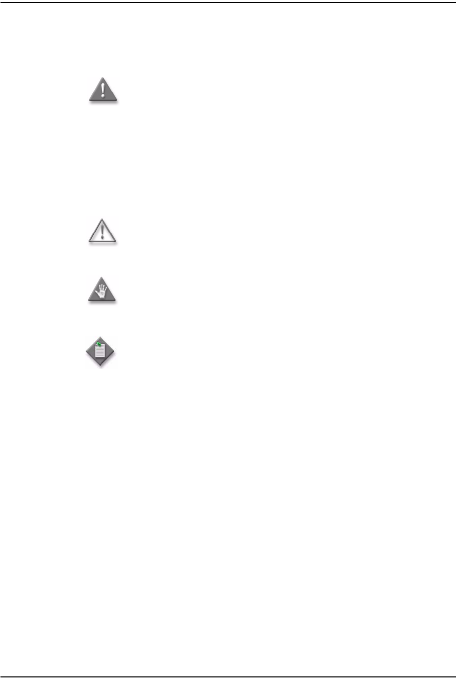
ii Mark the wall with the location of the mounting holes shown in
Figures 2-1 and 2-2. These holes should be the same distance apart as
the distance between the centers of the keyholes on the ONT. Use the
one of the two available fiber storage trays as a wall mounting template
to indicate the location of the mounting holes on the wall.
Figure 2-1 Wall mounting keyholes of the G-241W-A indoor ONT with fiber storage tray
attached
22441
Vertical
mounting
keyholes
Horizontal mounting keyholes
2 — Install a G-241W-A indoor ONT
Alcatel-Lucent 7368 ISAM ONT 2-5
Edition 01
I-240W-S I-241W-S I-241W-U Product Guide
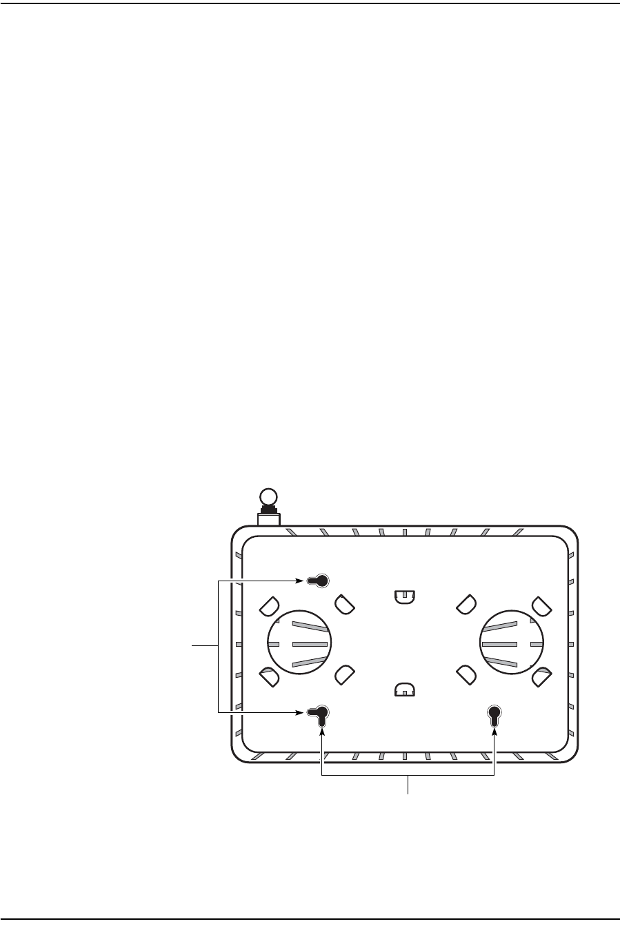
Figure 2-2 Wall mounting keyholes of the G-241W-A indoor ONT without fiber storage
tray attached
iii Attach the fiber storage tray to the wall by drilling the holes in the wall
where the tray will be mounted and then drive the mounting screws into
the holes.
Do not drive the mounting screws into the wall completely. Leave
approximately 1/8 in. (6 mm) between the screw head and the wall
surface.
iv Wrap the optic cable around the spools in the fiber storage tray.
vAttach the fiber storage tray to the wall by placing the screw heads of
the mounting screws into the wall mounting holes, either vertical or
horizontal, on the tray.
vi Slide the ONT enclosure over the fiber storage tray at a forty-five
degree angle and seat the ONT securely on the tray.
Aligning features molded into the fiber storage tray and ONT enclosure
interlock allowing the ONT to seat on the tray.
2Review the connection locations as shown in Figures 2-3 and 2-4.
22443
Vertical
mounting
keyholes
Horizontal mounting keyholes
2 — Install a G-241W-A indoor ONT
2-6 Alcatel-Lucent 7368 ISAM ONT
Edition 01
I-240W-S I-241W-S I-241W-U Product Guide
Figure 2-3 G-241W-A indoor ONT connections
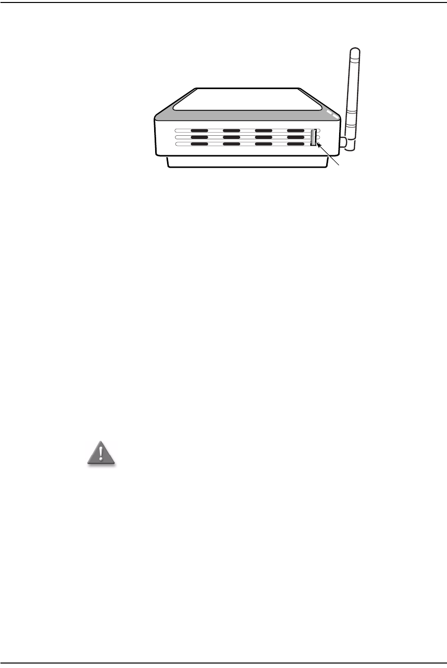
Figure 2-4 G-241W-A indoor ONT connections (USB host port)
3Connect the Ethernet cables directly to the RJ-45 ports. See Figure 2-3 for the
location of the RJ-45 ports.
4Connect the POTS cables directly to the RJ-11 ports. See Figure 2-3 for the
location of the RJ-11 ports.
5If used, connect the coaxial cable to the F-type connector. See Figure 2-3 for the
location of the F-type connector.
Danger — A shock hazard exists when working with the coaxial cable
for the RF video connection. Wear protective gloves and take all
necessary precautions to ensure personal safety.
Wi-Fi
Protected
Service button
Reset
button
POTS
ports
(RJ-11)
Ethernet
ports
(RJ-45)
Fiber
optic
connector
Power
connector
Power
on/off
switch
F-type
coaxial
connector
22788
USB port
22788

2 — Install a G-241W-A indoor ONT
Alcatel-Lucent 7368 ISAM ONT 2-7
Edition 01
I-240W-S I-241W-S I-241W-U Product Guide
6Connect the SC/APC fiber optic cable directly to the ONT. See Figure 2-3 for
location of the fiber optic connector.
7Install the power supply according to manufacturer specifications.
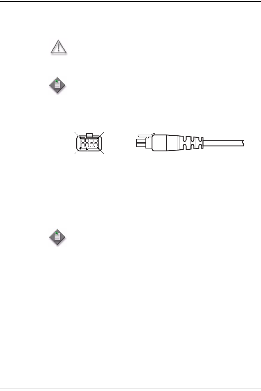
8Connect the power cable with an 8-pin Molex connector to the power supply.
9Connect the power cable with an 8-pin Molex connector to the ONT unit; see
Figure 2-5 for the Molex pin alignment.
Note 1 — Observe the following:
•To comply with FCC standards, use either RG-6 or RG-59 coaxial
cable. Also, proper attenuation must be inserted at the coaxial
output to guarantee that at the end of any coaxial drop, every video
signal is below 15.5 dBmV and audio signals are below 2.55 dBmV
(per channel).
•You may need to install the 75-ohm coaxial F connector on the video
cable.
Note 2 — Observe the following when connecting the F-type coaxial
connector to the coaxial connector on the ONT:
•Fully tighten the F-type connector on the cable by hand before using
a wrench to complete tightening (up to a maximum of an additional
1/8 turn). If using a torque wrench (as is recommended) to tighten
the connector, the torque setting should be between a minimum of
20 in-lbs and a maximum of 40 in-lbs. The connector should be tight
enough when the task is complete that it can not be unscrewed by
hand.
Danger — Fiber cables transmit invisible laser light. To avoid eye
damage or blindness, never look directly into fibers, connectors, or
adapters.
Warning — Be careful to maintain a bend radius of no less than 1.5 in.
(3.8 cm) when connecting the fiber optic cable. Too small of a bend
radius in the cable can result in damage to the optic fiber.
Note — Fiber cable preparation varies depending on the type and size
of the inside or outside plant fiber cable being spliced to the SC/APC
fiber optic pigtail cable.
Warning — To avoid the possibility of damage to the pins on the power
cable connector, carefully align the pins on the connector on the cable
with the pin holes in the power connector on the ONT before making the
connection.

2 — Install a G-241W-A indoor ONT
2-8 Alcatel-Lucent 7368 ISAM ONT
Edition 01
I-240W-S I-241W-S I-241W-U Product Guide
Figure 2-5 Molex 8-pin connector
10 Power up the ONT unit by using the on/off power switch; see Figure 2-3 for the
location of the power switch.
11 If used, enable the Wi-Fi service, as described in Configure a G-241W-A indoor
ONT.
12 Verify the ONT LEDs, voltage status, and optical signal levels; see the 7368
Hardware and Cabling Installation Guide.
13 Activate and test the services; see the 7368 Hardware and Cabling Installation
Guide.
14 If used, configure the SLID; see the 7368 ISAM ONT Configuration, Management,
and Troubleshooting Guide for more information.
15 If necessary, reset the ONT.
iAccess the Rest button. See Figure 2-3 for the location of the Reset button.
ii Insert the end of a straightened paper clip or other narrow object into the
hole in the Reset button to reset the ONT.
16 STOP. This procedure is complete.
Note — Observe the following:
•Only Pins 1, 2, and 7 in the Molex connector pin arrangement shown
in Figure 2-5 are used with G-241W-A indoor ONTs.
Pin 2 Pin 8
Pin 1 Pin 3 Pin 7
20179


3 — Replace a G-241W-A indoor ONT
3-2 Alcatel-Lucent 7368 ISAM ONT
Edition 01
I-240W-S I-241W-S I-241W-U Product Guide
3.1 Purpose
This chapter provides the steps to replace a G-241W-A indoor ONT.
3.2 General
The steps listed in this chapter describe mounting and cabling for G-241W-A indoor
ONTs.
3.3 Prerequisites
You need the following items before beginning the installation:
•all required cables
3.4 Recommended tools
You need the following tools for replacing the ONT:
•#2 Phillips screwdriver
•1/4 in. (6 mm) flat blade screwdriver
•wire strippers
•fiber optic splicing tools
•RJ-45 cable plug crimp tool
•voltmeter or multimeter
•optical power meter
•drill and drill bits

3 — Replace a G-241W-A indoor ONT
Alcatel-Lucent 7368 ISAM ONT 3-3
Edition 01
I-240W-S I-241W-S I-241W-U Product Guide
3.5 Safety information
Read the following safety information before replacing the unit.
Danger 1 — Hazardous electrical voltages and currents can cause
serious physical harm or death. Always use insulated tools and follow
proper safety precautions when connecting or disconnecting power
circuits.
Danger 2 — Make sure all sources of power are turned off and have
no live voltages present on feed lines or terminals. Use a voltmeter to
measure for voltage before proceeding.
Danger 3 — Always contact the local utility company before
connecting the enclosure to the utilities.
Warning — This equipment is ESD sensitive. Proper ESD
protections should be used when removing the fiber access cover of
the indoor ONT.
Caution — Keep indoor ONTs out of direct sunlight. Prolonged
exposure to direct sunlight can damage the unit.
Note 1 — Observe the local and national laws and regulations that
may be applicable to this installation.
Note 2 — Observe the following:
•The indoor ONT should be installed in accordance with the
applicable requirements of the NEC or CEC. Local authorities and
practices take precedent when there is conflict between the local
standard and the NEC or CEC.
•The indoor ONT must be installed by qualified service personnel.
•Indoor ONTs must be installed with cables that are suitably rated
and listed for indoor use.
•See the detailed specifications in the G-241W-A unit data sheet for
the ONT temperature ranges for these ONTs.
3 — Replace a G-241W-A indoor ONT
3-4 Alcatel-Lucent 7368 ISAM ONT
Edition 01
I-240W-S I-241W-S I-241W-U Product Guide
3.6 Procedure
Use this procedure to replace a G-241W-A indoor ONT.
1Deactivate the ONT services at the P-OLT.
If you are using the SLID feature, this step is not required. The ONT and the
services can remain in service (IS).
iUse the RTRV-ONT command to verify the ONT status and th associated
services. Record the serial number or the SLID of the ONT displayed in the
command output.
Example:
RTRV-ONT::ONT-1-1-1-1-1;
ii If the ONT is in service, place the ONT in OOS state.
Example:
ED-ONT::ONT-1-1-1-1-1;
2If used, disable the Wi-Fi service, as described in Configure a G-241W-A indoor
ONT.
3Power down the unit by using the on/off power switch; see Figure 3-1 for the
location of the power button.
4Disconnect the POTS, Ethernet and power and coaxial cables, as well as fiber optic
cables from the ONT; see Figure 3-1 for the connector locations on G-241W-A
indoor ONTs.
Attach the fiber dust cover to the end of the SC/APC connector.
Figure 3-1 G-241W-A ONT connections
See Figure 3-2 for the location of the USB ports on the G-241W-A.
Wi-Fi
Protected
Service button
Reset
button
POTS
ports
(RJ-11)
Ethernet
ports
(RJ-45)
Fiber
optic
connector
Power
connector
Power
on/off
switch
F-type
coaxial
connector
22788
3 — Replace a G-241W-A indoor ONT
Alcatel-Lucent 7368 ISAM ONT 3-5
Edition 01
I-240W-S I-241W-S I-241W-U Product Guide
Figure 3-2 G-241W-A indoor ONT connections (USB host port)
5Replace the ONT with a new unit:
aOn a flat surface, such as a desk, substitute a replacement ONT for the old
ONT.
bOn a wall.
iSlide the old ONT off of the mounting screws until the ONT is free of the
wall.
ii Slide the wall mount holes on the ONT enclosure or fiber storage tray of
the new ONT over the mounting screws until it is securely seated.
6Connect the Ethernet cables directly to the RJ-45 ports; see Figure 3-1 for the
location of the RJ-45 ports.
7Connect the POTS cables directly to the RJ-11 ports; see Figure 3-1 for the
location of the RJ-11 ports.
8If used, connect the coaxial cable to the F-type connector. See Figure 3-1 for
location of the F-type connector.
Danger — A shock hazard exists when working with the coaxial cable
for the RF video connection. Wear protective gloves and take all
necessary precautions to ensure personal safety.
USB port
22788

3 — Replace a G-241W-A indoor ONT
3-6 Alcatel-Lucent 7368 ISAM ONT
Edition 01
I-240W-S I-241W-S I-241W-U Product Guide
9If required, have approved service personnel who are trained to work with optic
fiber clean the fiber optic connection. See the 7368 ISAM ONT Configuration,
Management, and Troubleshooting Guide for more information about fiber optic
handling, inspection, and cleaning.
10 Connect the SC/APC fiber optic cable directly to the SC/APC adapter; see Figure
3-1 for the location of the SC/APC adapter.
11 Install the power supply according to manufacturer specifications.
12 Connect the power cable with an 8-pin Molex connector to the power supply.
Note 1 — Observe the following:
•To comply with FCC standards, use either RG-6 or RG-59 coaxial
cable. Also, proper attenuation must be inserted at the coaxial
output to guarantee that at the end of any coaxial drop, every video
signal is below 15.5 dBmV and audio signals are below 2.55 dBmV
(per channel).
•You may need to install the 75-ohm coaxial F connector on the video
cable.
Note 2 — Observe the following when connecting the F-type coaxial
connector to the coaxial connector on the ONT:
•Fully tighten the F-type connector on the cable by hand before using
a wrench to complete tightening (up to a maximum of an additional
1/8 turn). If using a torque wrench (as is recommended) to tighten
the connector, the torque setting should be between a minimum of
20 in-lbs and a maximum of 40 in-lbs. The connector should be tight
enough when the task is complete that it can not be unscrewed by
hand.
Danger — Fiber optic cables transmit invisible laser light. To avoid eye
damage or blindness, never look directly into fibers, connectors, or
adapters.
Danger — Fiber cables transmit invisible laser light. To avoid eye
damage or blindness, never look directly into fibers, connectors, or
adapters.
Warning — Be careful to maintain a bend radius of no less than 1.5 in.
(3.8 cm) when connecting the fiber optic cable. Too small of a bend
radius in the cable can result in damage to the optic fiber.
Note — Fiber cable preparation varies depending on the type and size
of the inside or outside plant fiber cable being spliced to the SC/APC
fiber optic pigtail cable.
3 — Replace a G-241W-A indoor ONT
Alcatel-Lucent 7368 ISAM ONT 3-7
Edition 01
I-240W-S I-241W-S I-241W-U Product Guide
13 Connect the power cable with an 8-pin Molex connector to the ONT unit; see
Figure 3-3 for the Molex pin alignment.
Figure 3-3 Molex 8-pin connector
14 Power up the unit by using the on/off power switch; see Figure 3-1 for the location
of the power switch.
15 If used, enable the Wi-Fi service, as described in Configure a G-241W-A indoor ONT
16 If used, configure the SLID; see the 7368 ISAM ONT Configuration, Management,
and Troubleshooting Guide for more information.
17 Verify the ONT LEDs, voltage status, and optical signal levels; see the 7368
Hardware and Cabling Installation Guide.
18 Activate and test the services; see the 7368 Hardware and Cabling Installation
Guide.
19 If necessary, reset the ONT.
iAccess the Rest button. See Figure 3-1 for the location of the Reset button.
ii Insert the end of a straightened paper clip or other narrow object into the
hole in the Reset button to reset the ONT.
20 STOP. This procedure is complete.
Warning — To avoid the possibility of damage to the pins on the power
cable connector, carefully align the pins on the connector on the cable
with the pin holes in the power connector on the ONT before making the
connection.
Note — Observe the following:
•Only Pins 1, 2, and 7 in the Molex connector arrangement shown in
Figure 3-3 are used with the G-241W-A indoor ONT.
Note — A new SLID or the old SLID may be used with the replacement
ONT. If a new SLID is used, the new SLID must also be programmed at
the P-OLT using TL1 or a network manager. If the old SLID is used, no
changes need to be made at the P-OLT; see the operations and
maintenance documentation for the OLT for more details.
Pin 2 Pin 8
Pin 1 Pin 3 Pin 7
20179

3 — Replace a G-241W-A indoor ONT
3-8 Alcatel-Lucent 7368 ISAM ONT
Edition 01
I-240W-S I-241W-S I-241W-U Product Guide


4 — Configure a G-241W-A indoor ONT
4-2 Alcatel-Lucent 7368 ISAM ONT
Edition 01
I-240W-S I-241W-S I-241W-U Product Guide
4.1 General
Please refer to the configuration information provided with your OLT for the
software configuration procedure for a G-241W-A ONT.
For HTTP configuration procedures, please refer to the 7368 ISAM ONT
Configuration, Management, and Troubleshooting Guide.
4.2 HGU mode GUI configuration
Use the procedures below to use the web-based GUI for the G-241W-A in HGU
mode. This mode is preset at delivery.
A home gateway unit (HGU) is a home networking device, used as a gateway to
connect devices in the home through fiber to the Internet. An HGU provides a variety
of features for the home network including routing and firewall capability. By using
the HGU, users can connect all smart equipment in their home, including personal
computers, set-top boxes, mobile phones, and other consumer electronics devices, to
the Internet.
Login
Use the procedure below to log in to the web-based GUI for the G-241W-A.
Procedure 4-1 Login to web-based GUI
1Open a web browser and enter the IP address of the ONT in the address bar.
The login window appears.
The default gateway IP address is http://192.168.1.254. You can connect to this
IP address using your web browser after connecting your PC to one of Ethernet
ports of the ONT. The static IP address of your PC must be in the same subnet as
the ONT.
2Enter your username and password in the Log in window, as shown in Figure 4-1.
The default username and password are printed on the ONT. The default user
name is userAdmin. The default superuser name is adminGPON. Contact
Alcatel-Lucent for the superuser password.

4 — Configure a G-241W-A indoor ONT
Alcatel-Lucent 7368 ISAM ONT 4-3
Edition 01
I-240W-S I-241W-S I-241W-U Product Guide
Figure 4-1 Web login window
3Click Login.
4STOP. This procedure is complete.
Device and connection status
G-241W-A ONTs support the retrieval of a variety of device and connection
information, including:
•device information
•LAN status
•WAN status
•WAN status IPv6
•Home networking information
•Optics module status
•Voice information
Caution — If you reset the router to recover the default username and
password, all other router configuration settings will also be restored to
their factory default values.
Note — If you forget the current username and password, press the
reset button for 5 s and the default values for the username and
password will be recovered at startup.
4 — Configure a G-241W-A indoor ONT
4-4 Alcatel-Lucent 7368 ISAM ONT
Edition 01
I-240W-S I-241W-S I-241W-U Product Guide
Procedure 4-2 Device information retrieval
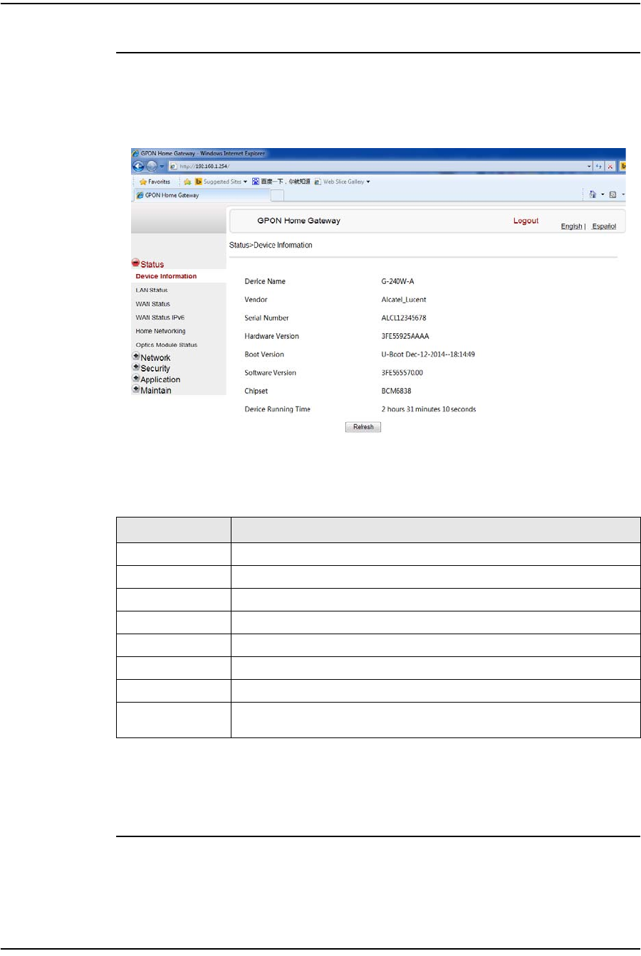
1Select Status > Device Information from the top-level menu in the GPON Home
Gateway window, as shown in Figure 4-2.
Figure 4-2 Device Information window
Table 4-1 describes the fields in the Device Information window.
Table 4-1 Device Information parameters
2Click Refresh to update the displayed information.
3STOP. This procedure is complete.
Field Description
Device Name Name on the ONT
Vendor Name of the vendor
Serial Number Serial number of the ONT
Hardware version Hardware version of the ONT
Boot version Boot version of the ONT
Software version Software version of the ONT
Chipset Chipset of the ONT
Device Running
Time Amount of time the device has run since last reset in hours, minutes, and
seconds
4 — Configure a G-241W-A indoor ONT
Alcatel-Lucent 7368 ISAM ONT 4-5
Edition 01
I-240W-S I-241W-S I-241W-U Product Guide
Procedure 4-3 LAN status retrieval
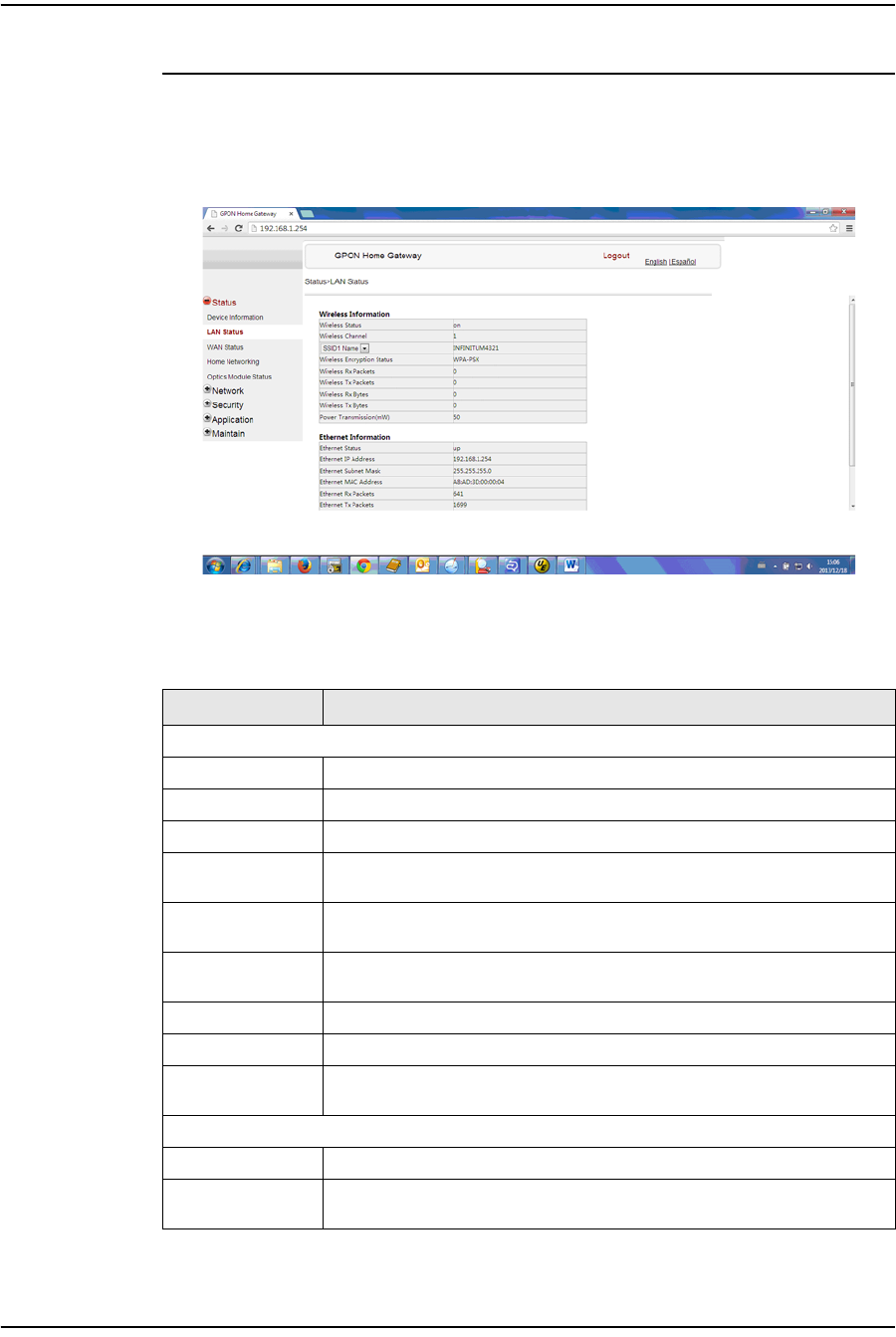
1Select Status > LAN Status from the top-level menu in the GPON Home Gateway
window, as shown in Figure 4-3.
Figure 4-3 LAN status window
Table 4-2 describes the fields in the LAN status window.
Table 4-2 LAN status parameters
Field Description
Wireless Information
Wireless Status Indicates whether the wireless is on or off
Wireless Channel Wireless channel number
SSID Name Name of each SSID
Wireless
Encryption Status Encryption type used on the wireless connection
Wireless Rx
Packets Number of packets received on the wireless connection
Wireless Tx
Packets Number of packets transmitted on the wireless connection
Wireless Rx Bytes Number of bytes received on the wireless connection
Wireless Tx Bytes Number of bytes transmitted on the wireless connection
Power
Transmission (mW) Power of the wireless transmission, in mW
Ethernet Information
Ethernet Status Indicates whether the Ethernet connection is on or off
Ethernet IP
Address IP address of the Ethernet connection
(1 of 2)
4 — Configure a G-241W-A indoor ONT
4-6 Alcatel-Lucent 7368 ISAM ONT
Edition 01
I-240W-S I-241W-S I-241W-U Product Guide
2Click Refresh to update the displayed information.
3STOP. This procedure is complete.
Procedure 4-4 WAN status retrieval
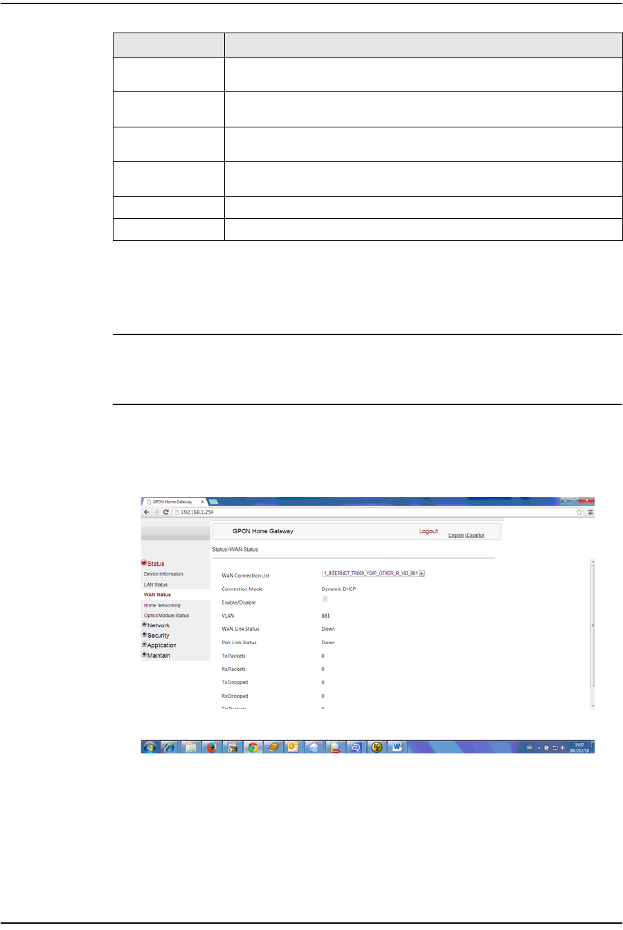
1Select Status > WAN Status from the top-level menu in the GPON Home Gateway
window, as shown in Figure 4-4.
Figure 4-4 WAN status window
Table 4-3 describes the fields in the WAN status window.
Ethernet Subnet
Mask Subnet Mask of the Ethernet connection
Ethernet MAC
Address MAC address of the Ethernet connection
Ethernet Rx
Packets Number of packets received on the Ethernet connection
Ethernet Tx
Packets Number of packets transmitted on the Ethernet connection
Ethernet Rx Bytes Number of bytes received on the Ethernet connection
Ethernet Tx Bytes Number of bytes transmitted on the Ethernet connection
Field Description
(2 of 2)
4 — Configure a G-241W-A indoor ONT
Alcatel-Lucent 7368 ISAM ONT 4-7
Edition 01
I-240W-S I-241W-S I-241W-U Product Guide
Table 4-3 WAN status parameters
2Click Refresh to update the displayed information.
3STOP. This procedure is complete.
Procedure 4-5 WAN status IPv6 retrieval
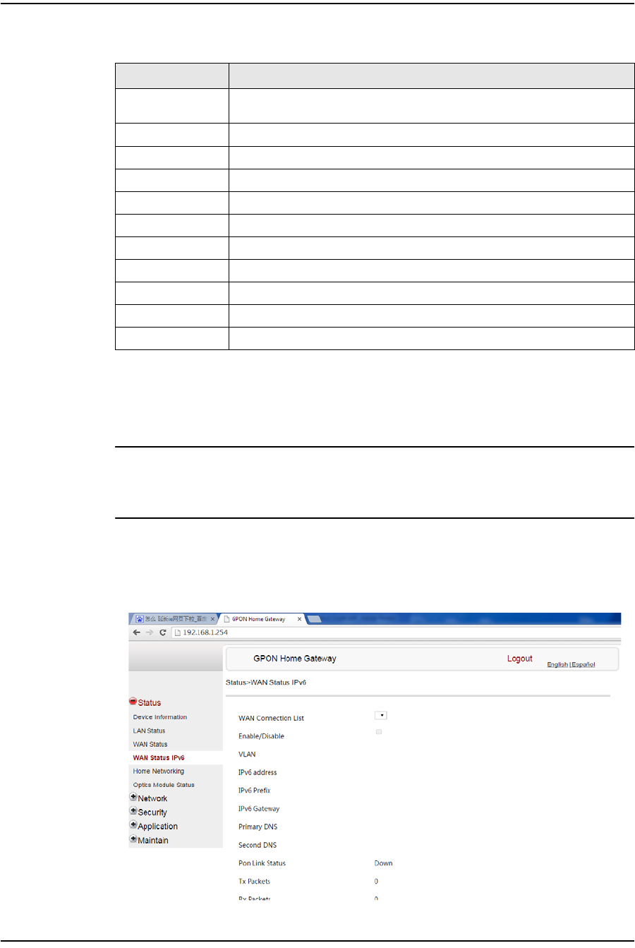
1Select Status > WAN Status IPv6 from the top-level menu in the GPON Home
Gateway window, as shown in Figure 4-5.
Figure 4-5 WAN status IPv6 window
Field Description
WAN connection
list Drop-down menu listing all WAN connections. The connection shown is the
connection for which WAN status will be shown.
Connection Mode Connection mode of the WAN connection
Enable/Disable Select this checkbox to enable the WAN connection
VLAN VLAN ID
WAN Link Status Whether the WAN link is up or down
Pon Link Status Whether the PON link is up or down
Tx Packets Number of packets transmitted on the WAN connection
Rx Packets Number of packets received on the WAN connection
Tx Dropped Number of packets dropped on the transmit WAN connection
Rx Dropped Number of packets dropped on the receive WAN connection
Err Packets Number of errored packets on the WAN connection

4 — Configure a G-241W-A indoor ONT
4-8 Alcatel-Lucent 7368 ISAM ONT
Edition 01
I-240W-S I-241W-S I-241W-U Product Guide
Table 4-4 describes the fields in the WAN status IPv6 window.
Table 4-4 WAN status IPv6 parameters
2Click Refresh to update the displayed information.
3STOP. This procedure is complete.
Field Description
WAN connection
list Drop-down menu listing all WAN connections. The connection shown is the
connection for which WAN status will be shown.
Enable/Disable Select this checkbox to enable the WAN connection
VLAN VLAN ID
IPv6 Address IPv6 Address that identifies the device and its location
IPv6 Prefix IPv6 prefix
IPv6 Gateway IPv6 gateway address
Primary DNS Primary Domain Name Server
Second DNS Secondary Domain Name Server
Pon Link Status Whether the PON link is up or down
Tx Packets Number of packets transmitted on the WAN connection
Rx Packets Number of packets received on the WAN connection
Tx Dropped Number of packets dropped on the transmit WAN connection
Rx Dropped Number of packets dropped on the receive WAN connection
Err Packets Number of errored packets on the WAN connection
4 — Configure a G-241W-A indoor ONT
Alcatel-Lucent 7368 ISAM ONT 4-9
Edition 01
I-240W-S I-241W-S I-241W-U Product Guide
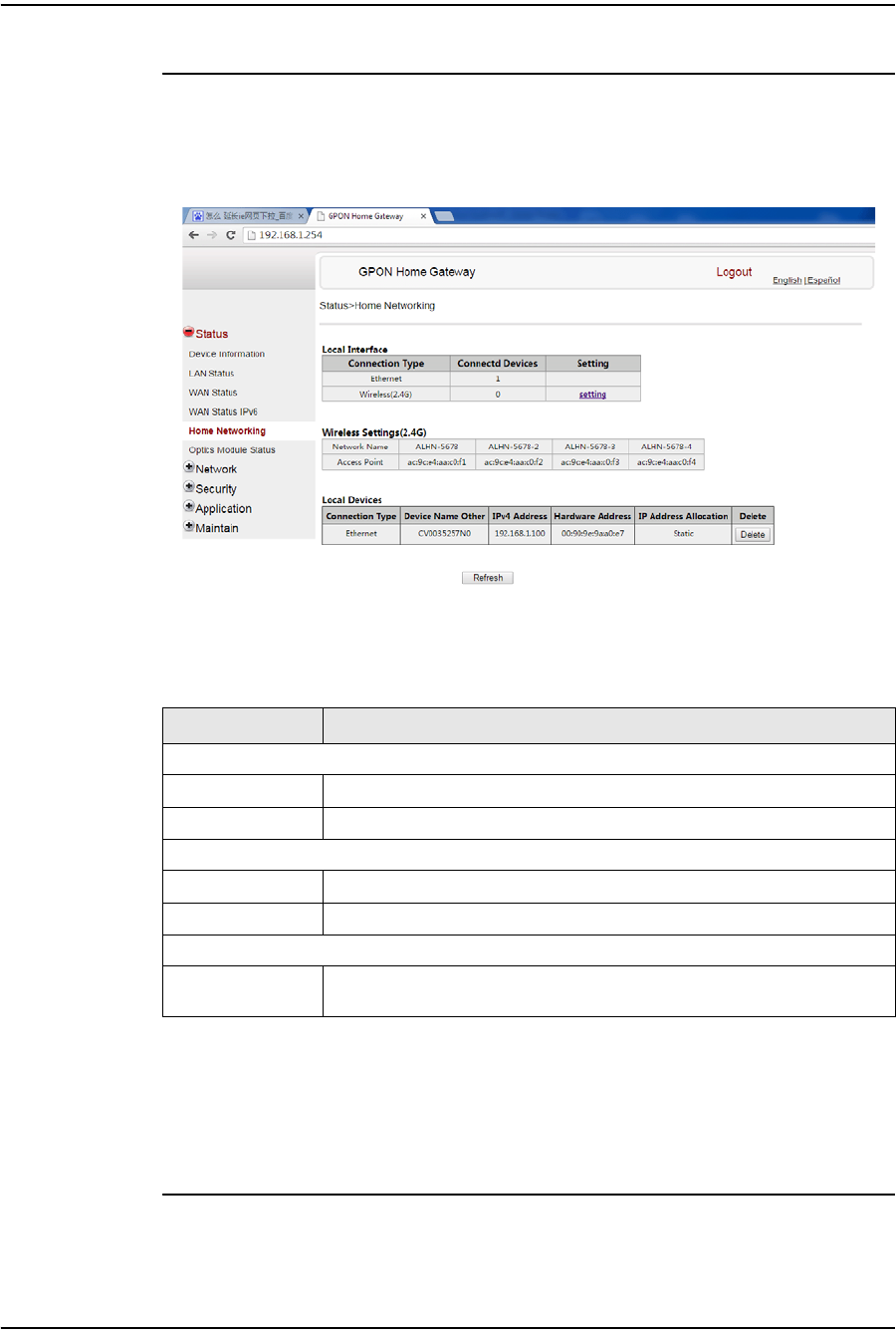
Procedure 4-6 Home networking information retrieval
1Select Status > Home Networking from the top-level menu in the GPON Home
Gateway window, as shown in Figure 4-6.
Figure 4-6 Home networking information window
Table 4-5 describes the fields in the Home networking window.
Table 4-5 Home networking parameters
2Click Delete to delete a particular local device connection.
3Click Refresh to update the displayed information.
4STOP. This procedure is complete.
Field Description
Local Interface
Ethernet Table displays the number of Ethernet connections and their settings
Wireless (2.4G) Table displays the number of wireless connections and their settings
Wireless Settings (2.4G)
Network Name Name of the wireless network
Access Point Hexadecimal address of the wireless access point
Local Devices
Table entry Each entry indicates the connection type, device name, IPv4 address,
hardware address, and IP address allocation of each connected local device.
4 — Configure a G-241W-A indoor ONT
4-10 Alcatel-Lucent 7368 ISAM ONT
Edition 01
I-240W-S I-241W-S I-241W-U Product Guide
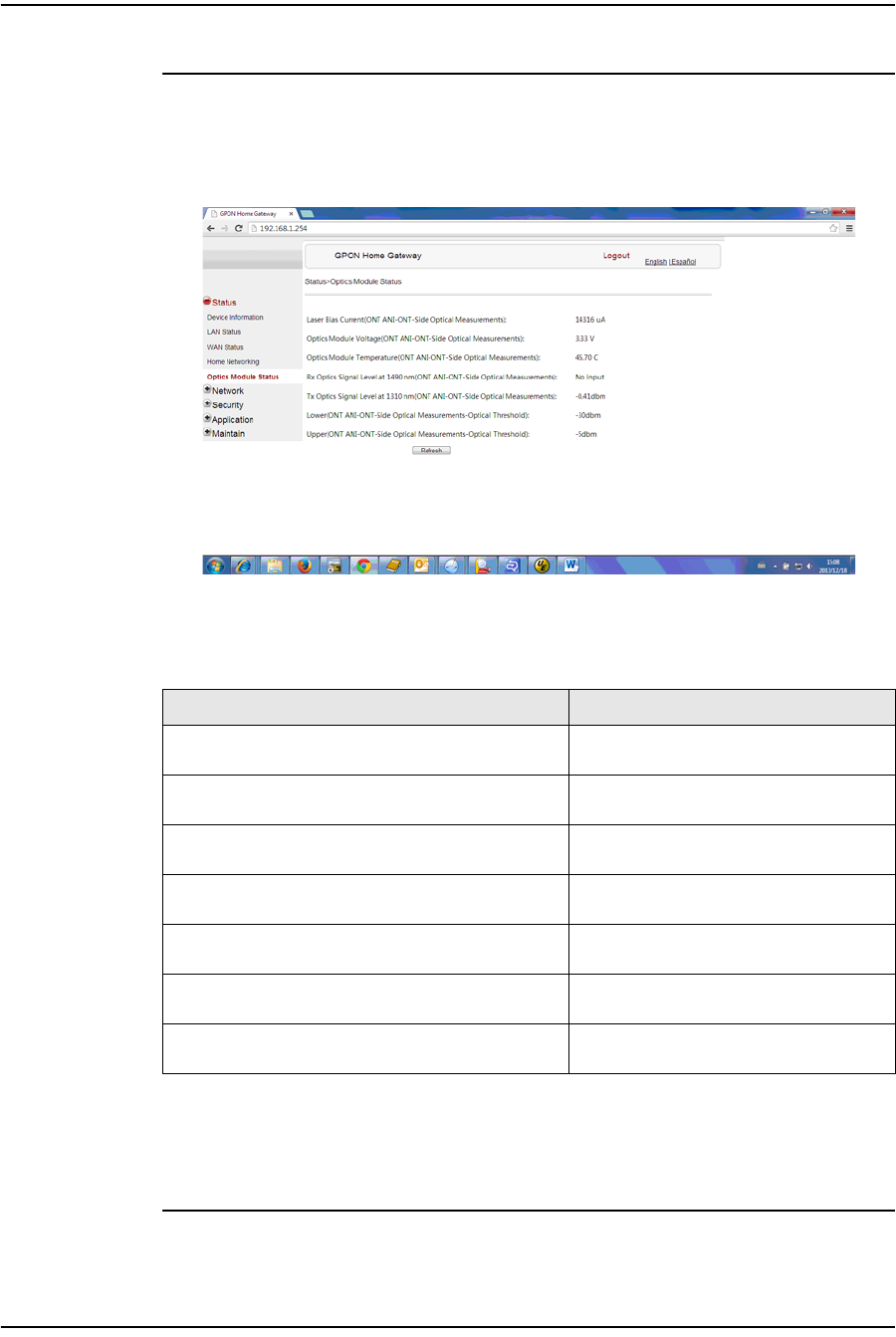
Procedure 4-7 Optics module status retrieval
1Select Status > Optics Module Status from the top-level menu in the GPON Home
Gateway window, as shown in Figure 4-7.
Figure 4-7 Optics module status window
Table 4-6 describes the fields in the Optics module status window.
Table 4-6 Optics module status parameters
2Click Refresh to update the displayed information.
3STOP. This procedure is complete.
Field Description
Laser Bias Current (ONT ANI-ONT-Side Optical
Measurements) Laser bias current, measured in uA
Optics Module Voltage (ONT ANI-ONT-Side Optical
Measurements) Optics module voltage, measured in V
Optics Module Temperature (ONT ANI-ONT-Side
Optical Measurements) Optics module temperature, measured in
C
Rx Optics Signal Level at 1490 nm (ONT ANI-ONT-Side
Optical Measurements) Received optics signal level at 1490 nm,
measured in dBm
Tx Optics Signal Level at 1310 nm (ONT ANI-ONT-Side
Optical Measurements) Transmitted optics signal level at 1310 nm,
measured in dBm
Lower (ONT ANI-ONT-Side Optical
Measurements-Optical Threshold) Lower optical threshold, measured in dBm
Upper (ONT ANI-ONT-Side Optical
Measurements-Optical Threshold) Lower optical threshold, measured in dBm
4 — Configure a G-241W-A indoor ONT
Alcatel-Lucent 7368 ISAM ONT 4-11
Edition 01
I-240W-S I-241W-S I-241W-U Product Guide
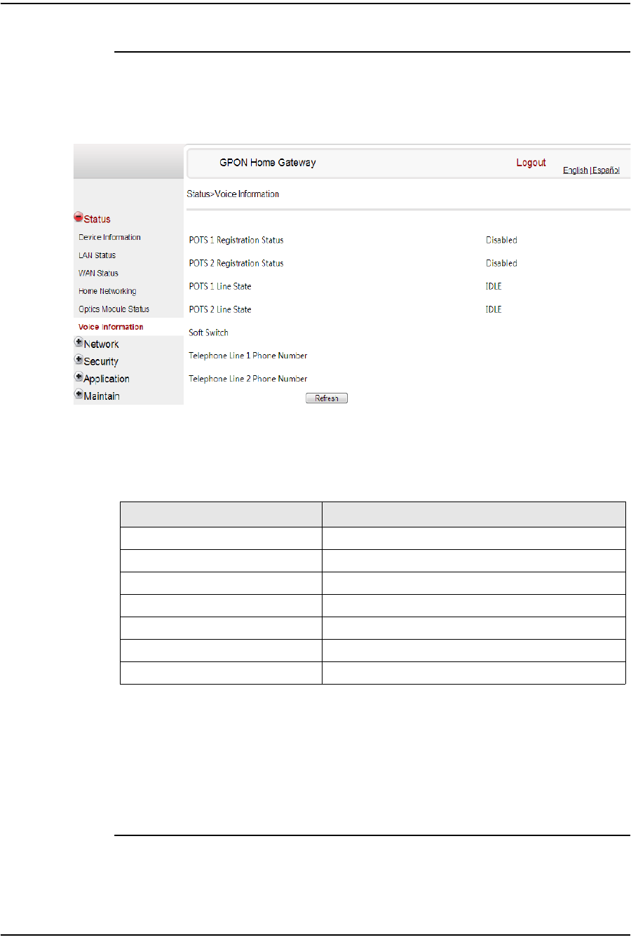
Procedure 4-8 Voice information retrieval
1Select Status > Voice Information from the top-level menu in the GPON Home
Gateway window, as shown in Figure 4-8.
Figure 4-8 Voice Information window
Table 4-7 describes the fields in the Voice Information window.
Table 4-7 Voice Information parameters
Notes
(1) This field is only visible at the adminGPON level; it is not visible at the userAdmin level.
2Click Refresh to update the displayed information.
3STOP. This procedure is complete.
Field Description
POTS 1 Registration Status Status of POTS port 1: registered or unregistered
POTS 2 Registration Status Status of POTS port 2: registered or unregistered
POTS 1 Line State State of POTS line 1: IDLE, Off Hook, or On Hook
POTS 2 Line State State of POTS line 2: IDLE, Off Hook, or On Hook
Softswitch(1) Proxy IP address; blank if the line is not registered
Telephone line 1 phone number(1) Phone number configured for telephone line 1
Telephone line 2 phone number(1) Phone number configured for telephone line 2
4 — Configure a G-241W-A indoor ONT
4-12 Alcatel-Lucent 7368 ISAM ONT
Edition 01
I-240W-S I-241W-S I-241W-U Product Guide
Network configuration
G-241W-A ONTs support network configuration, including:
•LAN
•LAN IPv6
•WAN
•WiFi
•Routing
•DNS
•TR-069
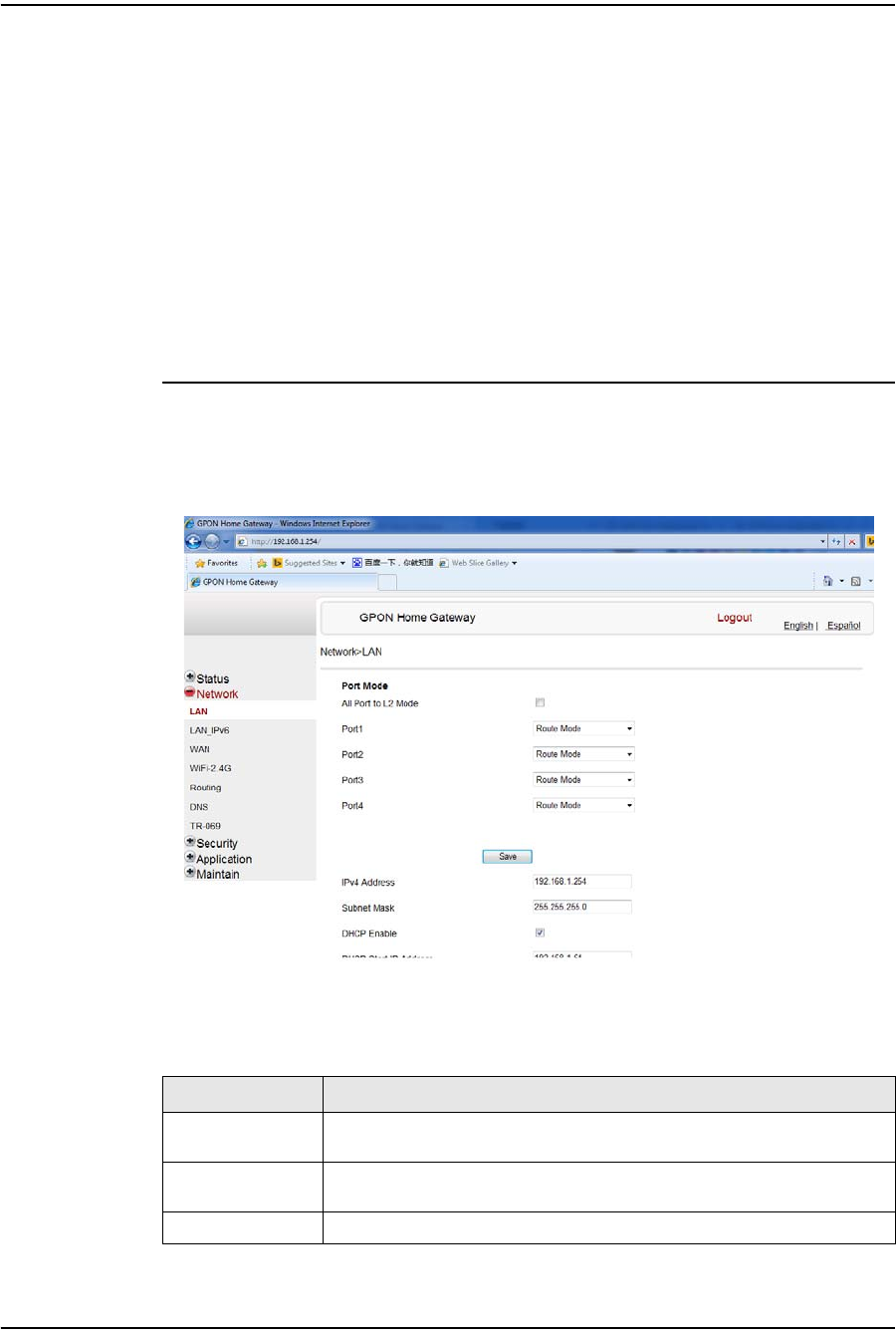
Procedure 4-9 LAN networking configuration
1Select Network > LAN from the top-level menu in the GPON Home Gateway
window, as shown in Figure 4-9.
Figure 4-9 LAN network window
Table 4-8 describes the fields in the LAN network window.
Table 4-8 LAN network parameters
Field Description
Port Mode:
All Port to L2 Mode Select this checkbox to set all ports to L2 mode
Port Mode
Port 1 - 4 Drop-down port mode for each port: Route mode or bridge mode
IPv4 Address IP Address of the ONT
(1 of 2)

4 — Configure a G-241W-A indoor ONT
Alcatel-Lucent 7368 ISAM ONT 4-13
Edition 01
I-240W-S I-241W-S I-241W-U Product Guide
2Select the mode for each port.
3Click Save.
4Enter the DHCP configuration information.
5Click Save.
6Bind a MAC address to the LAN by entering the MAC and IP addresses and then
clicking Add. Repeat for all MAC addresses to be bound.
7STOP. This procedure is complete.
Subnet Mask Subnet mask of the ONT
DHCP enable Select this checkbox to enable DHCP
DHCP Start IP
Address Starting DHCP IP address
DHCP End IP
Address Ending DHCP IP address
DHCP Lease Time DHCP lease time (in min)
Bind MAC Address MAC address to associate to the LAN
Bind IP Address IP address to associate to the bound MAC address
Field Description
(2 of 2)
4 — Configure a G-241W-A indoor ONT
4-14 Alcatel-Lucent 7368 ISAM ONT
Edition 01
I-240W-S I-241W-S I-241W-U Product Guide
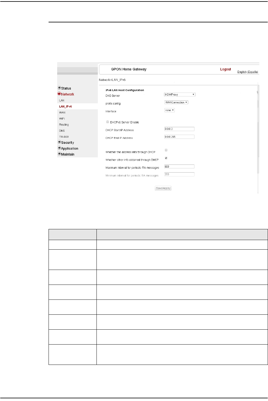
Procedure 4-10 LAN IPv6 networking configuration
1Select Network > LAN_IPv6 from the top-level menu in the GPON Home Gateway
window, as shown in Figure 4-10.
Figure 4-10 LAN IPv6 network window
Table 4-9 describes the fields in the LAN IPv6 network window.
Table 4-9 LAN IPv6 network parameters
Field Description
DNS Server Choose a DNS server from the drop-down menu.
prefix config Choose a prefix config option from the drop-down menu, either
WANConnection (prefix will be obtained from the WAN) or Static (enables you
to enter the prefix).
prefix This field appears if you selected the “Static” option for the “prefix config”
field. Type a connection.
Interface This field appears if you selected the Wan Connection option for the “prefix
config” field. Choose a WAN connection interface from the drop-down menu.
DHCPv6 Server
Enable Select this checkbox to enable DHCP IPv6 server.
DHCP Start IP
Address Enter the starting DHCP IP address.
DHCP End IP
Address Enter the ending DHCP IP address.
Whether the
address info
through DCHP
Select this checkbox to enable address information retrieval through DHCP.
(1 of 2)
4 — Configure a G-241W-A indoor ONT
Alcatel-Lucent 7368 ISAM ONT 4-15
Edition 01
I-240W-S I-241W-S I-241W-U Product Guide
2Choose a DNS server, prefix config, and interface.
3Select or enter the DHCP configuration information.
4Enter the maximum and minimum intervals for RA messages.
5Click Save/Apply.
6STOP. This procedure is complete.
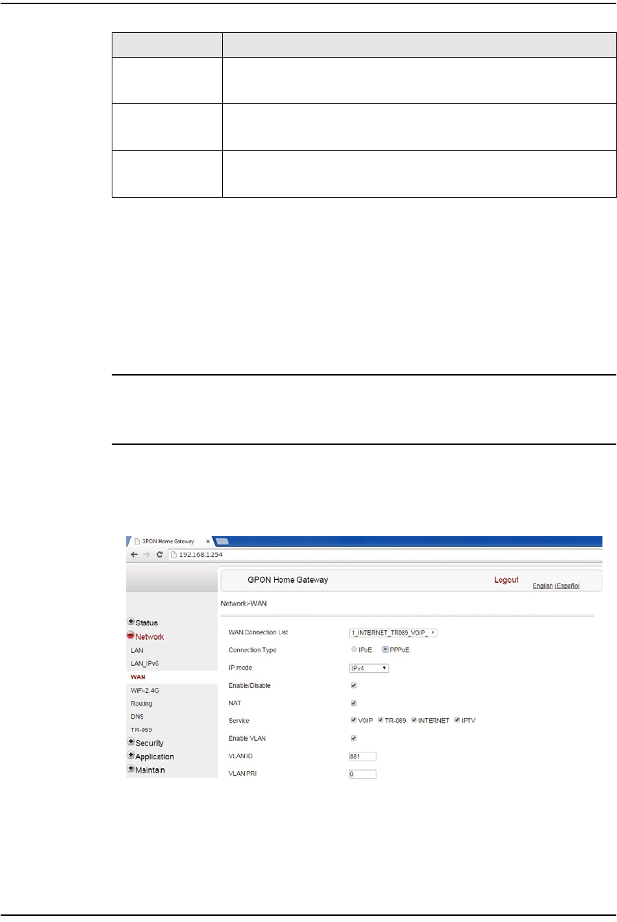
Procedure 4-11 WAN networking configuration
1Select Network > WAN from the top-level menu in the GPON Home Gateway
window, as shown in Figure 4-11.
Figure 4-11 WAN network window
Table 4-10 describes the fields in the WAN network window.
Whether other info
obtained through
DHCP
Select this checkbox to enable retrieval of other information through DHCP.
Maximum interval
for periodic RA
messages
Enter the maximum interval (in seconds) for periodic Router Advertisement
messages. The interval range is from 4 to 1800.
Minimum interval
for periodic RA
messages
Enter the minimum interval (in seconds) for periodic Router Advertisement
messages. The interval range is from 4 to 1800.
Field Description
(2 of 2)

4 — Configure a G-241W-A indoor ONT
4-16 Alcatel-Lucent 7368 ISAM ONT
Edition 01
I-240W-S I-241W-S I-241W-U Product Guide
Table 4-10 WAN network parameters
2Configure a specific WAN connection.
3Click Save.
4STOP. This procedure is complete.
Field Description
WAN Connection
List Choose a WAN connection from the drop-down menu to set the connection
parameters
Connection Type Select a connection type: IPoE or PPPoE
IP Mode Choose an IP mode from the drop-down menu: IPv4 or IPv6
Enable/Disable Select this checkbox to enable the WAN connection
NAT Select this checkbox to enable NAT
Service Select the checkboxes to enable service types for this connection
Enable VLAN Select this checkbox to enable VLAN
VLAN ID Enter the VLAN ID
VLAN PRI Enter the VLAN PRI
WAN IP Mode Choose an IP mode from the drop-down menu
Connection Trigger Choose a connection type from the drop-down menu
Username Enter the username
Password Enter the password
Keep Alive Time Enter the Keep Alive Time (from 5 to 60 seconds)
4 — Configure a G-241W-A indoor ONT
Alcatel-Lucent 7368 ISAM ONT 4-17
Edition 01
I-240W-S I-241W-S I-241W-U Product Guide
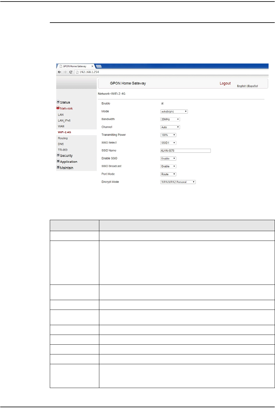
Procedure 4-12 WiFi networking configuration
1Select Network > WiFi from the top-level menu in the GPON Home Gateway
window, as shown in Figure 4-12.
Figure 4-12 WiFi network window
Table 4-11 describes the fields in the WiFi network window.
Table 4-11 WiFi network parameters
Field Description
Enable Select this checkbox to enable WiFi
Mode Choose a wi-fi mode from the drop-down menu:
•auto (b/g/n)
•b
•g
•n
•b/g
Bandwidth Choose a channel from the drop-down menu or choose Auto to have the
channel automatically assigned
Channel Choose a bandwidth option from the drop-down menu
Transmitting
Power Choose the percentage transmitting power from the drop-down menu
SSID Select Choose the SSID from the drop-down menu
SSID Name Enter the SSID name
Enable SSID Enable or disable SSID from this drop-down menu
SSID Broadcast Enable or disable SSID broadcast from this drop-down menu
Port Mode Choose a port mode from the drop-down menu:
•Route
•Bridge
(1 of 2)

4 — Configure a G-241W-A indoor ONT
4-18 Alcatel-Lucent 7368 ISAM ONT
Edition 01
I-240W-S I-241W-S I-241W-U Product Guide
2Configure the WiFi connection.
3If you have enabled and configured WPS, click WPS connect.
4Click Save.
5STOP. This procedure is complete.
Encrypt Mode Choose an encryption mode from the drop-down menu:
•OPEN
•WEP
•WPA/WPA2 Personal
•WPA/WPA2 Enterprise
WPA Version Choose a WPA version from the drop-down menu:
•WPA1
•WPA2
•WPA1/WPA2
WPA Encryption
Mode Choose a WPA encryption mode from the drop-down menu:
•TKIP
•AES
•TKIP/AES
WPA Key Enter the WPA key
Enable WPS Enable or disable WPS from this drop-down menu
WPS Mode Choose a WPS mode from the drop-down menu:
•PBC
•PIN
PIN Code Number Enter the WPS PIN
Field Description
(2 of 2)
4 — Configure a G-241W-A indoor ONT
Alcatel-Lucent 7368 ISAM ONT 4-19
Edition 01
I-240W-S I-241W-S I-241W-U Product Guide
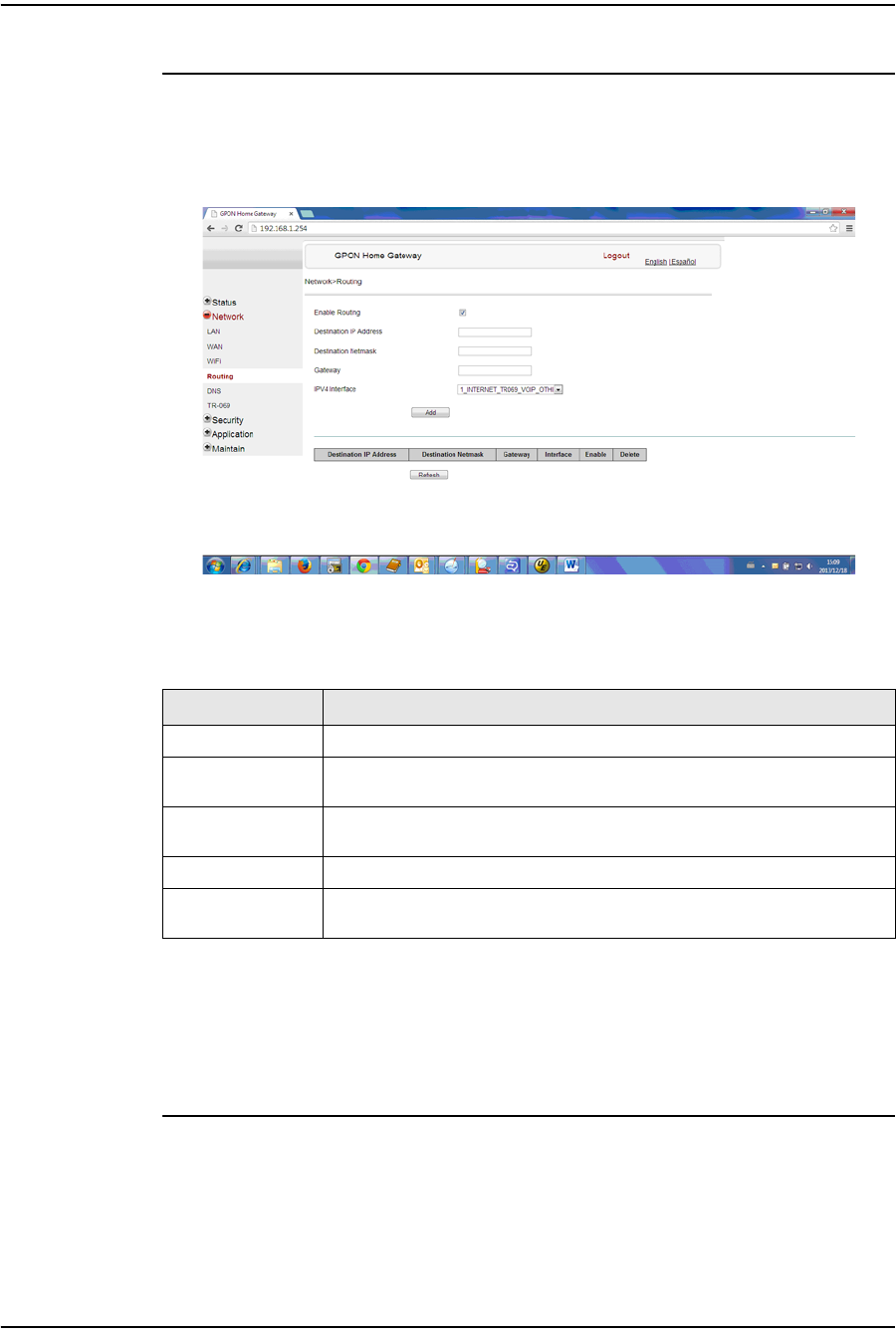
Procedure 4-13 Routing configuration
1Select Network > Routing from the top-level menu in the GPON Home Gateway
window, as shown in Figure 4-13.
Figure 4-13 Routing network window
Table 4-12 describes the fields in the Routing network window.
Table 4-12 Routing network parameters
2Enter the routing information.
3Click Add.
4STOP. This procedure is complete.
Field Description
Enable Routing Select this checkbox to enable routing
Destination IP
Address Enter the destination IP address
Destination
Netmask Enter the destination network mask
Gateway Enter the gateway address
IPv4 Interface Choose a WAN connection previously created in the WAN network window
from the drop-down menu
4 — Configure a G-241W-A indoor ONT
4-20 Alcatel-Lucent 7368 ISAM ONT
Edition 01
I-240W-S I-241W-S I-241W-U Product Guide
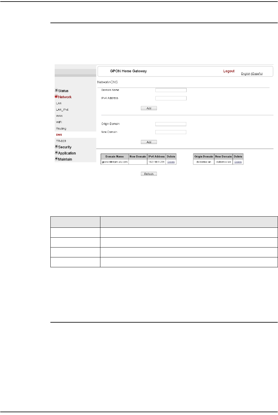
Procedure 4-14 DNS configuration
1Select Network > DNS from the top-level menu in the GPON Home Gateway
window, as shown in Figure 4-14.
Figure 4-14 DNS network window
Table 4-13 describes the fields in the DNS network window.
Table 4-13 DNS network parameters
2Enter the domain name and IP address and click Add.
3If required, associate an origin domain with a new domain, click Add.
4STOP. This procedure is complete.
Field Description
Domain Name Domain name
IPv4 Address Domain IP address
Origin Domain Origin domain name
New Domain New domain name
4 — Configure a G-241W-A indoor ONT
Alcatel-Lucent 7368 ISAM ONT 4-21
Edition 01
I-240W-S I-241W-S I-241W-U Product Guide
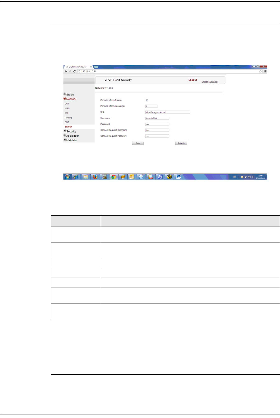
Procedure 4-15 TR-069 configuration
1Select Network > TR-069 from the top-level menu in the GPON Home Gateway
window, as shown in Figure 4-15.
Figure 4-15 TR-069 network window
Table 4-14 describes the fields in the TR-069 network window.
Table 4-14 TR-069 network parameters
2Configure TR-069 by entering the required information.
3Click Save.
4STOP. This procedure is complete.
Field Description
Periodic Inform
Enable Select this checkbox to enable periodic inform updates
Periodic Inform
Interval(s) Time between periodic inform updates, in seconds
URL URL of the auto-configuration server
Username Username used to log in to the ONT
Password Password used to log in to the ONT
Connect Request
Username Username used to log in to the auto-configuration server
Connect Request
Password Password used to log in to the auto-configuration server
4 — Configure a G-241W-A indoor ONT
4-22 Alcatel-Lucent 7368 ISAM ONT
Edition 01
I-240W-S I-241W-S I-241W-U Product Guide
Security configuration
G-241W-A ONTs support security configuration, including:
•firewall
•MAC filter
•IP filter
•URL filter
•DMZ and ALG
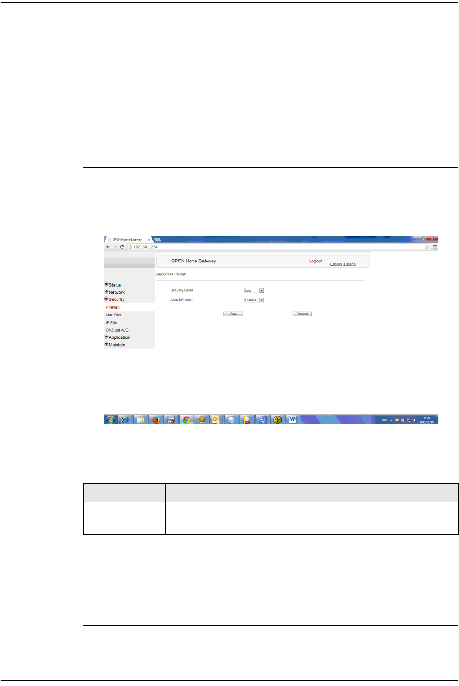
Procedure 4-16 Firewall configuration
1Select Security > Firewall from the top-level menu in the GPON Home Gateway
window, as shown in Figure 4-16.
Figure 4-16 Firewall window
Table 4-15 describes the fields in the firewall window.
Table 4-15 Firewall parameters
2Configure the firewall.
3Click Save.
4STOP. This procedure is complete.
Field Description
Security level Choose the security level from the drop-down menu
Attack Protect Enable or disable attack protect from the drop-down menu
4 — Configure a G-241W-A indoor ONT
Alcatel-Lucent 7368 ISAM ONT 4-23
Edition 01
I-240W-S I-241W-S I-241W-U Product Guide
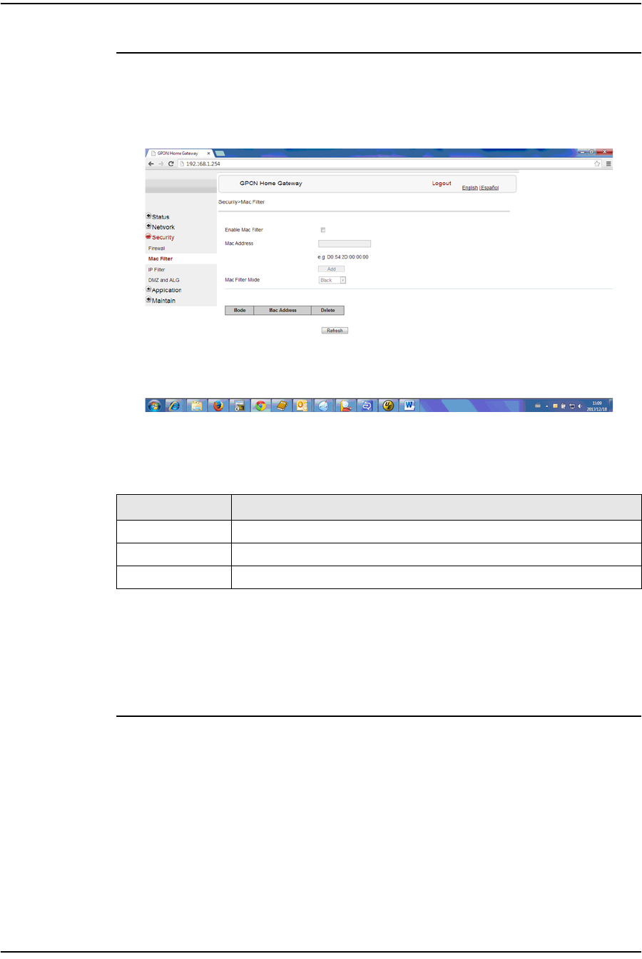
Procedure 4-17 MAC filter configuration
1Select Security > Mac Filter from the top-level menu in the GPON Home Gateway
window, as shown in Figure 4-17.
Figure 4-17 MAC filter window
Table 4-16 describes the fields in the MAC filter window.
Table 4-16 MAC filter parameters
2Configure a MAC filter.
3Click Add.
4STOP. This procedure is complete.
Field Description
Enable MAC filter Select this checkbox to enable the MAC filter
Mac Address MAC address
Mac Filter Mode Choose the MAC filter mode from this drop-down menu
4 — Configure a G-241W-A indoor ONT
4-24 Alcatel-Lucent 7368 ISAM ONT
Edition 01
I-240W-S I-241W-S I-241W-U Product Guide
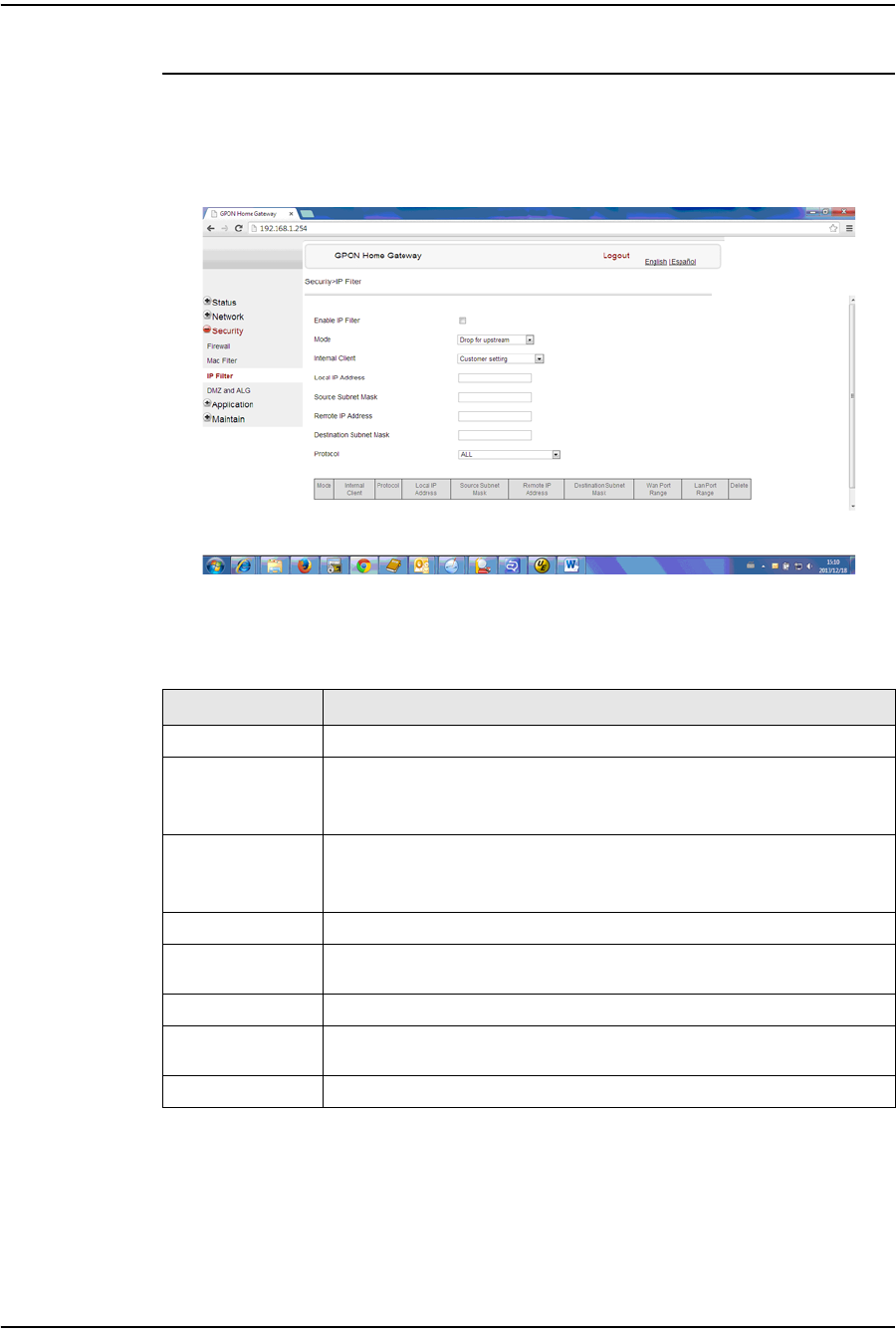
Procedure 4-18 IP filter configuration
1Select Security > IP filter from the top-level menu in the GPON Home Gateway
window, as shown in Figure 4-18.
Figure 4-18 IP filter window
Table 4-17 describes the fields in the IP filter window.
Table 4-17 IP filter parameters
2Configure the IP filter.
Field Description
Enable IP Filter Select this checkbox to enable an IP filter
Mode Choose an IP filter mode from the drop-down menu:
•Drop for upstream
•Drop for downstream
Internal Client Choose an internal client from the drop-down menu:
•Customer setting - uses the IP address input below
•IP - uses the connecting devices' IP to the ONT
Local IP Address Local IP address
Source Subnet
Mask Source subnet mask
Remote IP Address Remote IP address
Destination Subnet
Mask Destination subnet mask
Protocol Choose an application protocol or all from the drop-down menu
4 — Configure a G-241W-A indoor ONT
Alcatel-Lucent 7368 ISAM ONT 4-25
Edition 01
I-240W-S I-241W-S I-241W-U Product Guide
3Click Add.
4STOP. This procedure is complete.
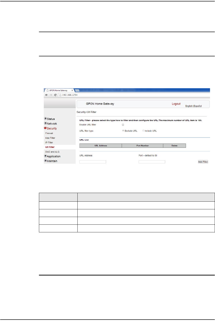
Procedure 4-19 URL filter configuration
1Select Security > URL Filter from the top-level menu in the GPON Home Gateway
window, as shown in Figure 4-19.
Figure 4-19 URL Filter window
Table 4-18 describes the fields in the URL Filter window.
Table 4-18 URL Filter parameters
2Configure the URL Filter.
3Click Add Filter.
4STOP. This procedure is complete.
Field Description
Enable URL filter Select the checkbox to enable the URL filter
URL filter type Select the checkbox for Exclude URL or Include URL
URL Address Type the URL address
Port Number Type the port number; the default is 80
4 — Configure a G-241W-A indoor ONT
4-26 Alcatel-Lucent 7368 ISAM ONT
Edition 01
I-240W-S I-241W-S I-241W-U Product Guide
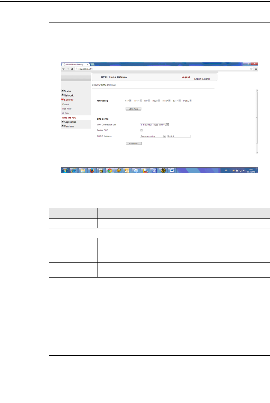
Procedure 4-20 DMZ and ALG configuration
1Select Security > DMZ and ALG from the top-level menu in the GPON Home
Gateway window, as shown in Figure 4-20.
Figure 4-20 DMZ and ALG window
Table 4-19 describes the fields in the DMZ and ALG window.
Table 4-19 DMZ and ALG parameters
2Configure ALG.
3Click Save ALG.
4Configure DMZ.
5Click Save DMZ.
6STOP. This procedure is complete.
Field Description
ALG Config Select the checkboxes to enable the protocols to be supported by the ALG
DMZ Config
WAN Connection
List Choose a WAN connection from the drop-down menu
Enable DMZ Select this checkbox to enable DMZ on the chosen WAN connection
DMZ IP Address Choose Customer Setting and enter the DMZ IP address or choose the IP
address of a connected device from the drop-down menu
4 — Configure a G-241W-A indoor ONT
Alcatel-Lucent 7368 ISAM ONT 4-27
Edition 01
I-240W-S I-241W-S I-241W-U Product Guide
Application configuration
G-241W-A ONTs support application configuration, including:
•port forwarding
•DDNS
•NTP
•USB storage
•UPnP and DLNA
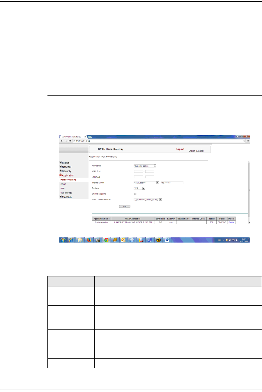
Procedure 4-21 Port forwarding configuration
1Select Application > Port forwarding from the top-level menu in the GPON Home
Gateway window, as shown in Figure 4-21.
Figure 4-21 Port forwarding window
Table 4-20 describes the fields in the port forwarding window.
Table 4-20 Port forwarding parameters
Field Description
APPName Choose an application name from the drop-down menu
WAN Port WAN port range
LAN Port LAN port range
Internal Client Choose a connected device from the drop-down menu and enter the
associated IP address
Protocol Choose the port forwarding protocol from the drop-down menu:
•TCP
•UDP
•TCP/UDP
Enable Mapping Select this checkbox to enable mapping
(1 of 2)
4 — Configure a G-241W-A indoor ONT
4-28 Alcatel-Lucent 7368 ISAM ONT
Edition 01
I-240W-S I-241W-S I-241W-U Product Guide
2Configure port forwarding.
3Click Add.
4STOP. This procedure is complete.
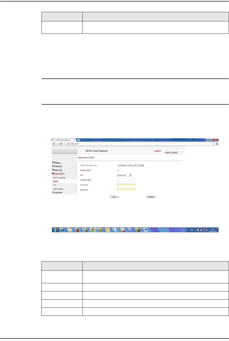
Procedure 4-22 DDNS configuration
1Select Application > DDNS from the top-level menu in the GPON Home Gateway
window, as shown in Figure 4-22.
Figure 4-22 DDNS window
Table 4-21 describes the fields in the DDNS window.
Table 4-21 DDNS parameters
WAN Connection
List Choose a WAN connection from the drop-down menu
Field Description
WAN Connection
List Choose a WAN connection from the drop-down menu
Enable DDNS Select this checkbox to enable DDNS on the chosen WAN connection
ISP Choose an ISP from the drop-down menu.
Domain Name Domain name
Username Username
(1 of 2)
Field Description
(2 of 2)
4 — Configure a G-241W-A indoor ONT
Alcatel-Lucent 7368 ISAM ONT 4-29
Edition 01
I-240W-S I-241W-S I-241W-U Product Guide
2Configure DDNS.
3Click Save.
4STOP. This procedure is complete.
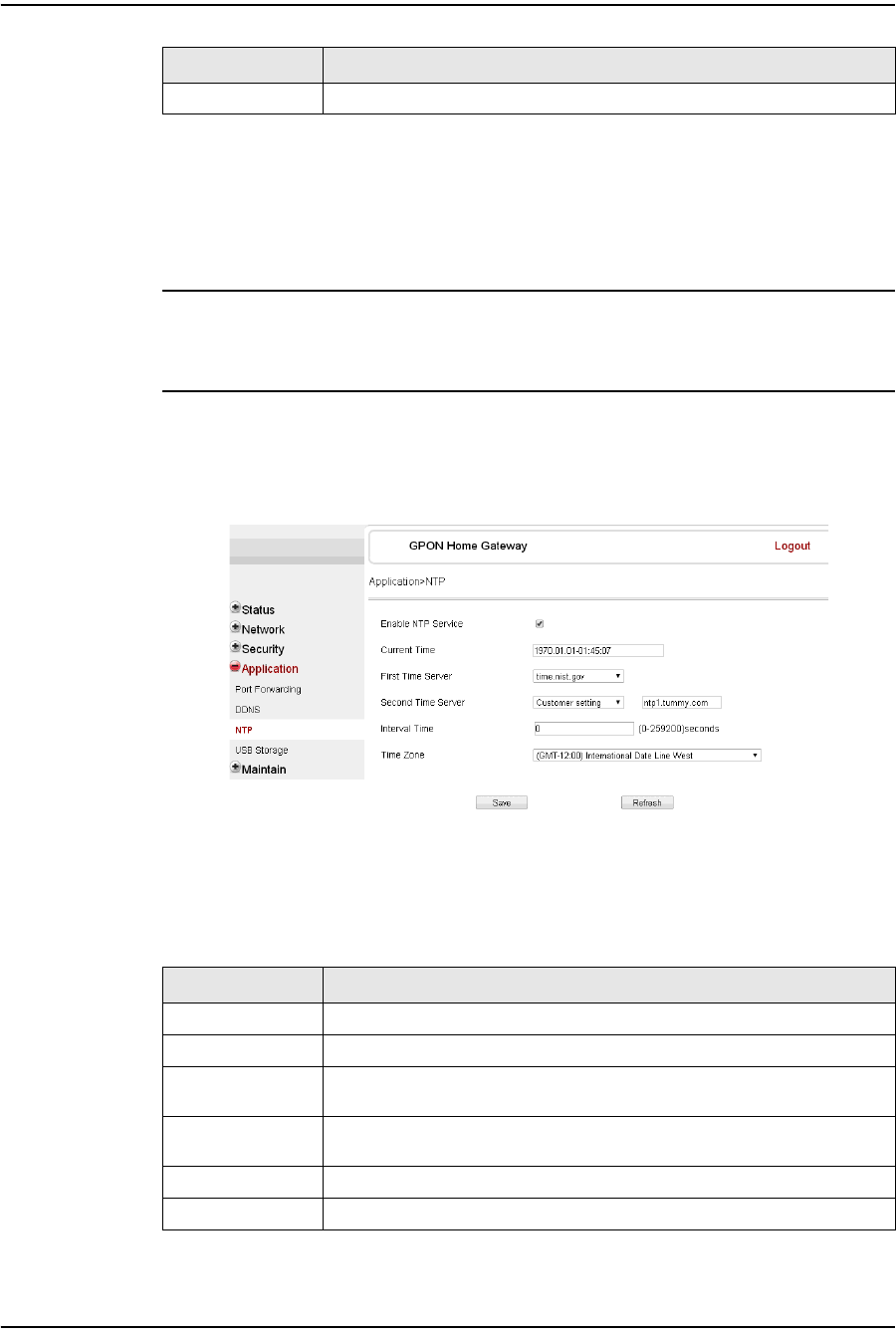
Procedure 4-23 NTP configuration
1Select Application > NTP from the top-level menu in the GPON Home Gateway
window, as shown in Figure 4-23.
Figure 4-23 NTP window
Table 4-22 describes the fields in the NTP window.
Table 4-22 NTP parameters
Password Password
Field Description
Enable NTP Service Select this checkbox to enable NTP service
Current Time Enter the current local date and time
First Time Server Choose a time server from the drop-down menu or choose Customer setting
and enter the address of the time server.
Second Time
Server Choose a time server from the drop-down menu or choose Customer setting
and enter the address of the time server.
Interval Time Interval at which to get the time from the time server, in seconds
Time Zone Choose the local time zone from the drop-down menu
Field Description
(2 of 2)
4 — Configure a G-241W-A indoor ONT
4-30 Alcatel-Lucent 7368 ISAM ONT
Edition 01
I-240W-S I-241W-S I-241W-U Product Guide
2Configure NTP.
3Click Save.
4STOP. This procedure is complete.
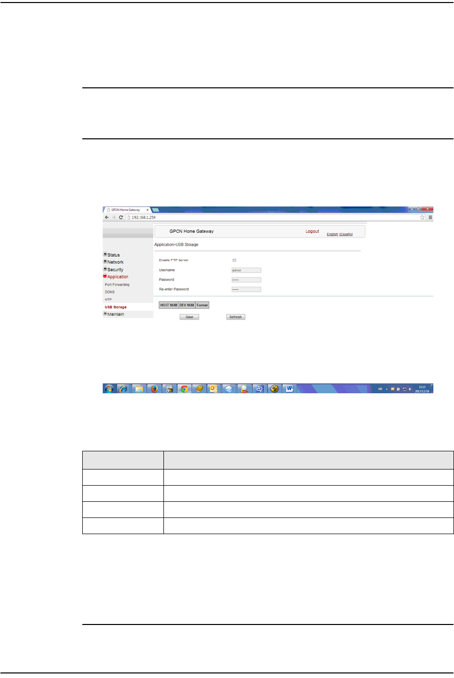
Procedure 4-24 USB storage configuration
1Select Application > USB storage from the top-level menu in the GPON Home
Gateway window, as shown in Figure 4-24.
Figure 4-24 USB storage window
Table 4-23 describes the fields in the USB storage window.
Table 4-23 USB storage parameters
2Configure USB storage.
3Click Save.
4STOP. This procedure is complete.
Field Description
Enable FTP server Select this checkbox to enable using an FTP server for data storage
Username Username for FTP server
Password Password for FTP server
Re-enter Password Password for FTP server
4 — Configure a G-241W-A indoor ONT
Alcatel-Lucent 7368 ISAM ONT 4-31
Edition 01
I-240W-S I-241W-S I-241W-U Product Guide
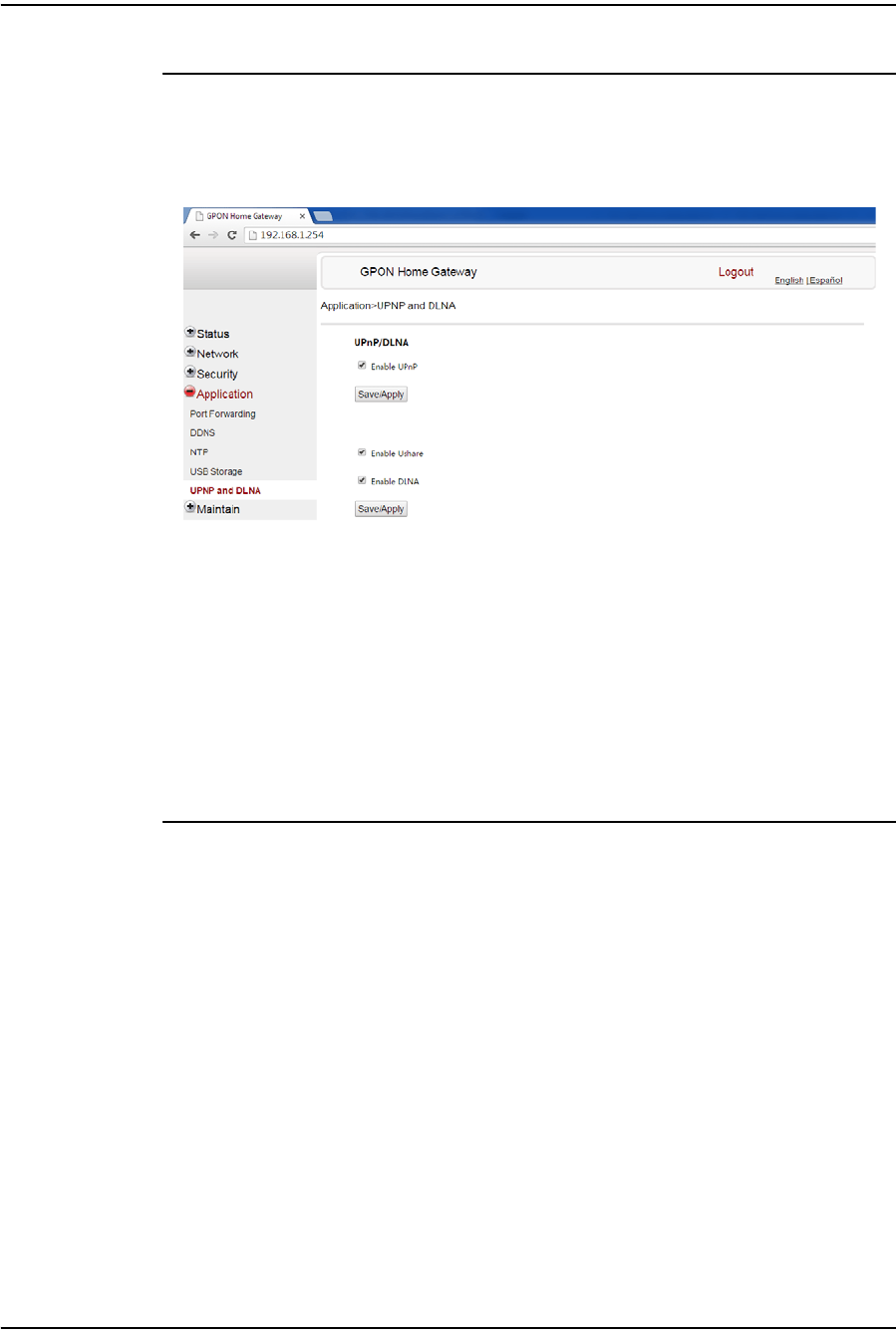
Procedure 4-25 UPnP and DLNA configuration
1Select Application > UPnP and DLNA from the top-level menu in the GPON Home
Gateway window, as shown in Figure 4-25.
Figure 4-25 UPnP and DLNA window
2Select the Enable UPnP checkbox to enable UPnP.
3Click Save/Apply.
4Select the Enable Ushare checkbox to enable Ushare (the UPnP/DLNA media
server).
5Select the Enable DLNA checkbox to enable DLNA.
6Click Save/Apply.
7STOP. This procedure is complete.
Maintenance
G-241W-A ONTs support maintenance tasks, including:
•password change
•LOID configuration
•SLID configuration
•device management
•backup and restore
•firmware upgrade
•device reboot
•restore factory defaults
•diagnose
•log
4 — Configure a G-241W-A indoor ONT
4-32 Alcatel-Lucent 7368 ISAM ONT
Edition 01
I-240W-S I-241W-S I-241W-U Product Guide
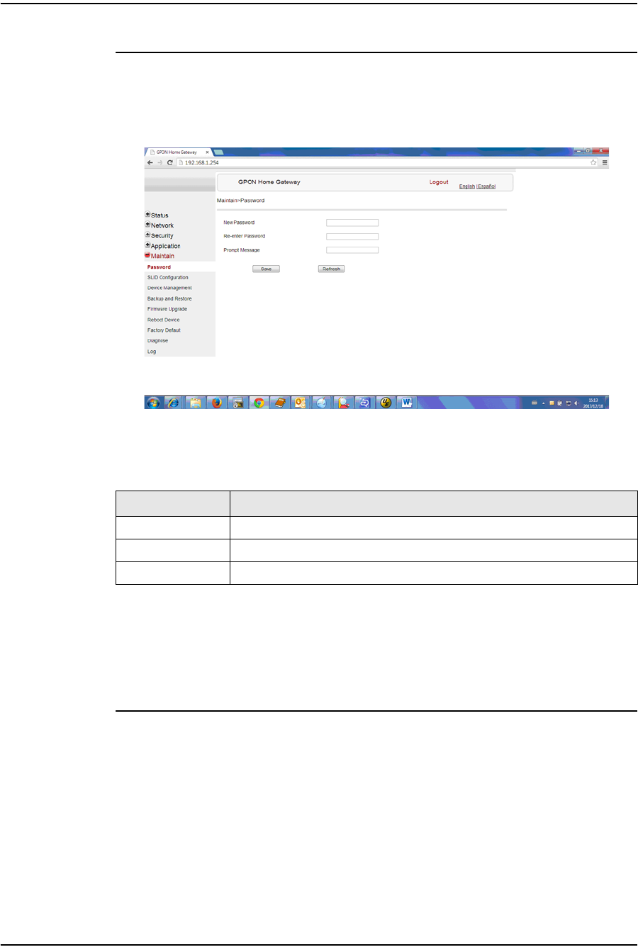
Procedure 4-26 Password configuration
1Select Maintain > Password from the top-level menu in the GPON Home Gateway
window, as shown in Figure 4-26.
Figure 4-26 Password window
Table 4-24 describes the fields in the password window.
Table 4-24 Password parameters
2Configure the new password.
3Click Save.
4STOP. This procedure is complete.
Field Description
New Password New password
Re-enter password Password must match password entered above
Prompt message Password prompt message
4 — Configure a G-241W-A indoor ONT
Alcatel-Lucent 7368 ISAM ONT 4-33
Edition 01
I-240W-S I-241W-S I-241W-U Product Guide
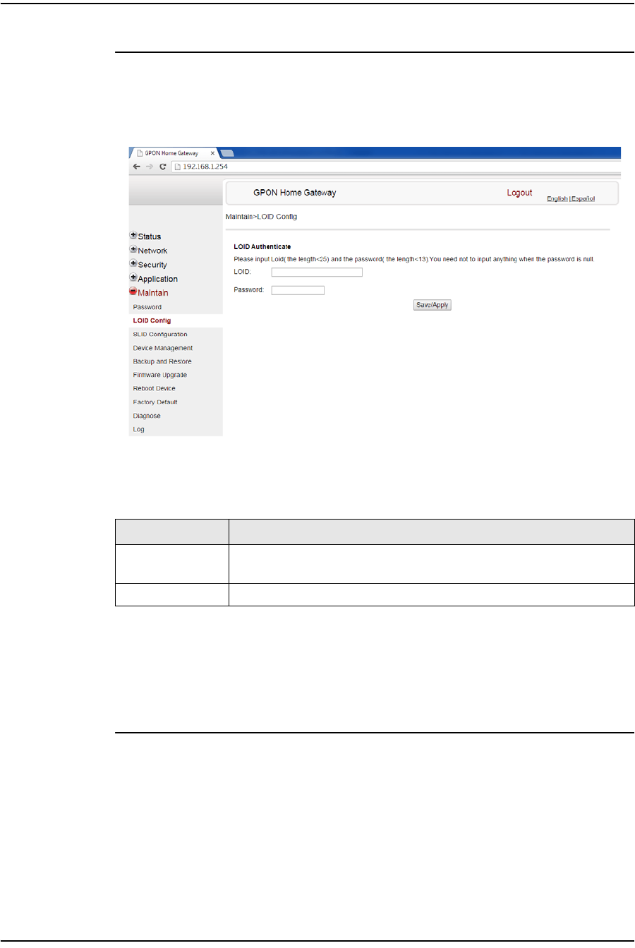
Procedure 4-27 LOID configuration
1Select Maintain > LOID Config from the top-level menu in the GPON Home Gateway
window, as shown in Figure 4-27.
Figure 4-27 LOID Config window
Table 4-25 describes the fields in the LOID configuration window.
Table 4-25 LOID configuration parameters
2Configure the LOID.
3Click Save/Apply.
4STOP. This procedure is complete.
Field Description
LOID Type the LOID; the maximum number of characters is 24
If the password is null, this field may be left blank
Password Type the password; the maximum number of characters is 12
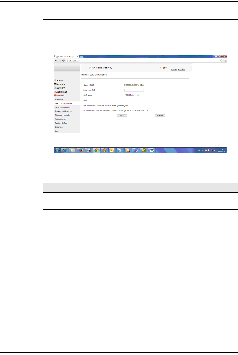
4 — Configure a G-241W-A indoor ONT
4-34 Alcatel-Lucent 7368 ISAM ONT
Edition 01
I-240W-S I-241W-S I-241W-U Product Guide
Procedure 4-28 SLID configuration
1Select Maintain > SLID Configuration from the top-level menu in the GPON Home
Gateway window, as shown in Figure 4-28.
Figure 4-28 SLID configuration window
Table 4-26 describes the fields in the SLID configuration window.
Table 4-26 SLID configuration parameters
2Configure the new SLID.
3Click Save.
4STOP. This procedure is complete.
Field Description
Current SLID Displays current SLID
Input new SLID Enter new SLID
SLID Mode Choose a SLID mode from the drop-down menu.
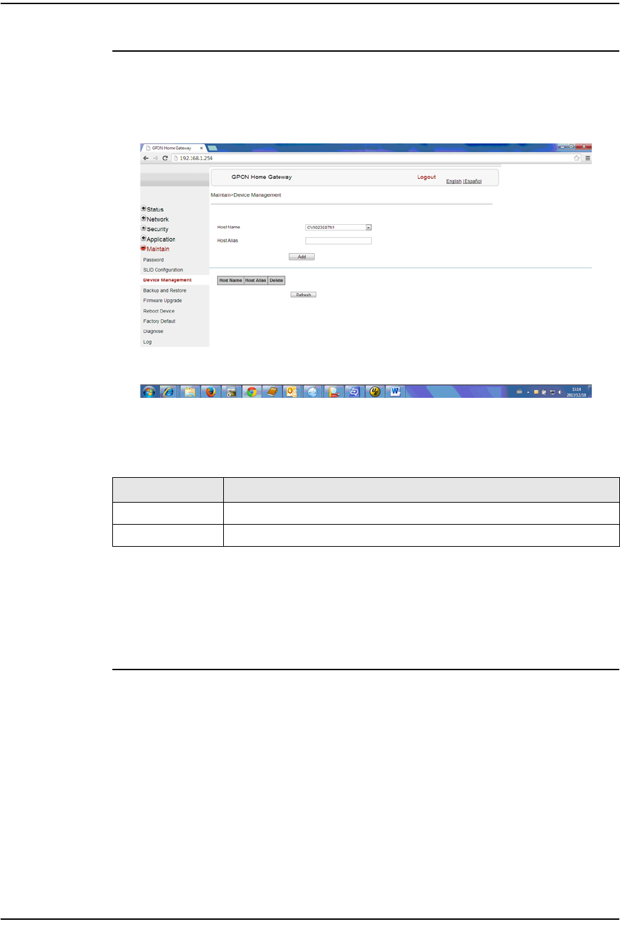
4 — Configure a G-241W-A indoor ONT
Alcatel-Lucent 7368 ISAM ONT 4-35
Edition 01
I-240W-S I-241W-S I-241W-U Product Guide
Procedure 4-29 Device management
1Select Maintain > Device Management from the top-level menu in the GPON Home
Gateway window, as shown in Figure 4-29.
Figure 4-29 Device management window
Table 4-27 describes the fields in the Device management window.
Table 4-27 Device management parameters
2Configure an alias for a specific host.
3Click Add.
4STOP. This procedure is complete.
Field Description
Host name Choose a host from the drop-down menu
Alias Enter an alias for the chosen host
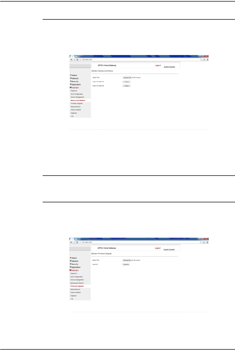
4 — Configure a G-241W-A indoor ONT
4-36 Alcatel-Lucent 7368 ISAM ONT
Edition 01
I-240W-S I-241W-S I-241W-U Product Guide
Procedure 4-30 Backup and restore
1Select Maintain > Backup and Restore from the top-level menu in the GPON Home
Gateway window, as shown in Figure 4-30.
Figure 4-30 Backup and Restore window
2Click Select File and choose the backup file.
3Click Import Config File to restore the ONT to the saved backup or click Export
Config File to export the current ONT configuration to the backup file.
4STOP. This procedure is complete.
Procedure 4-31 Upgrade firmware
1Select Maintain > Firmware Upgrade from the top-level menu in the GPON Home
Gateway window, as shown in Figure 4-31.
Figure 4-31 Firmware upgrade window
2Click Select File and choose the firmware file.
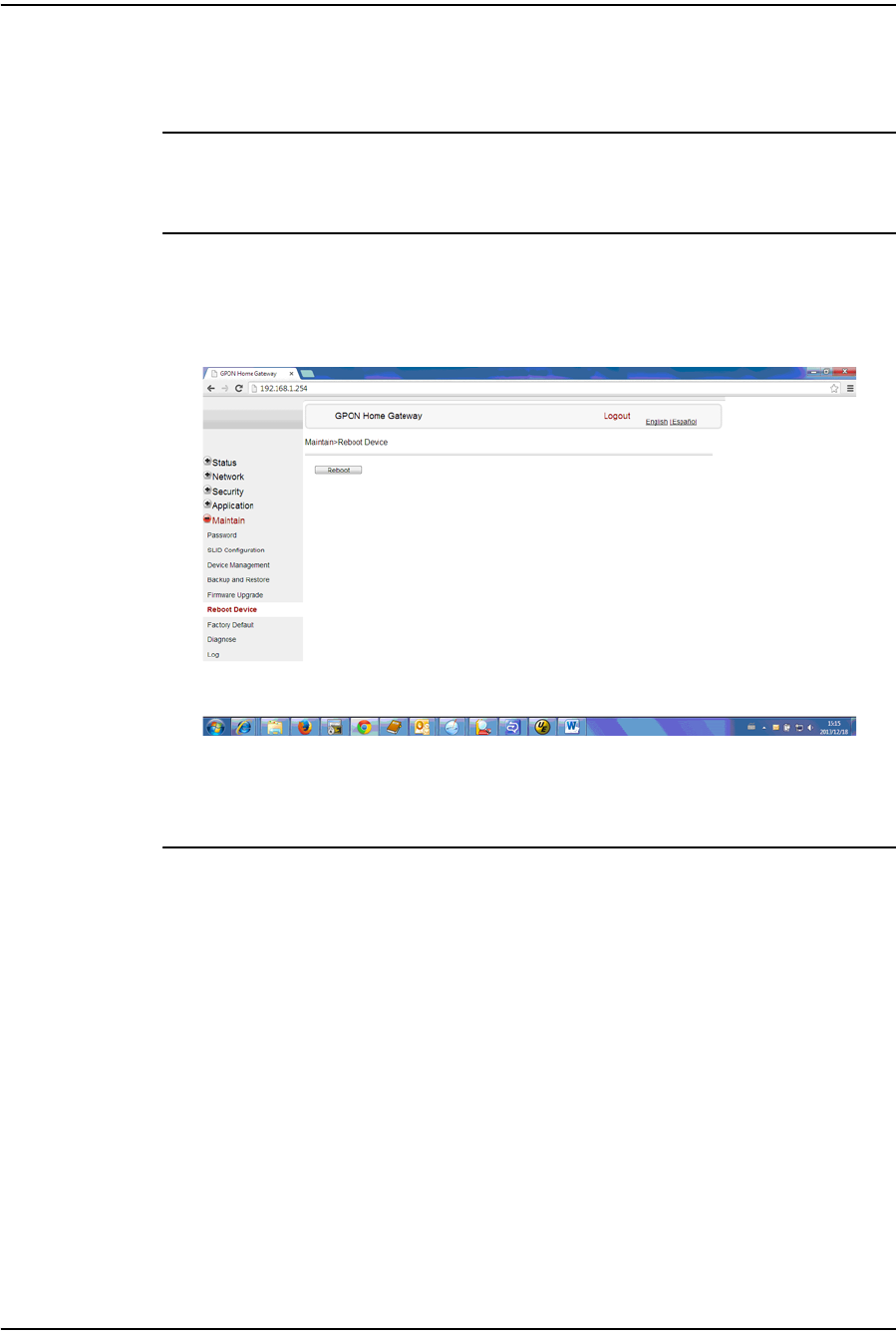
4 — Configure a G-241W-A indoor ONT
Alcatel-Lucent 7368 ISAM ONT 4-37
Edition 01
I-240W-S I-241W-S I-241W-U Product Guide
3Click Upgrade to upgrade the firmware.
4STOP. This procedure is complete.
Procedure 4-32 Reboot ONT
1Select Maintain > Reboot Device from the top-level menu in the GPON Home
Gateway window, as shown in Figure 4-32.
Figure 4-32 Reboot window
2Click Reboot to reboot the ONT.
3STOP. This procedure is complete.
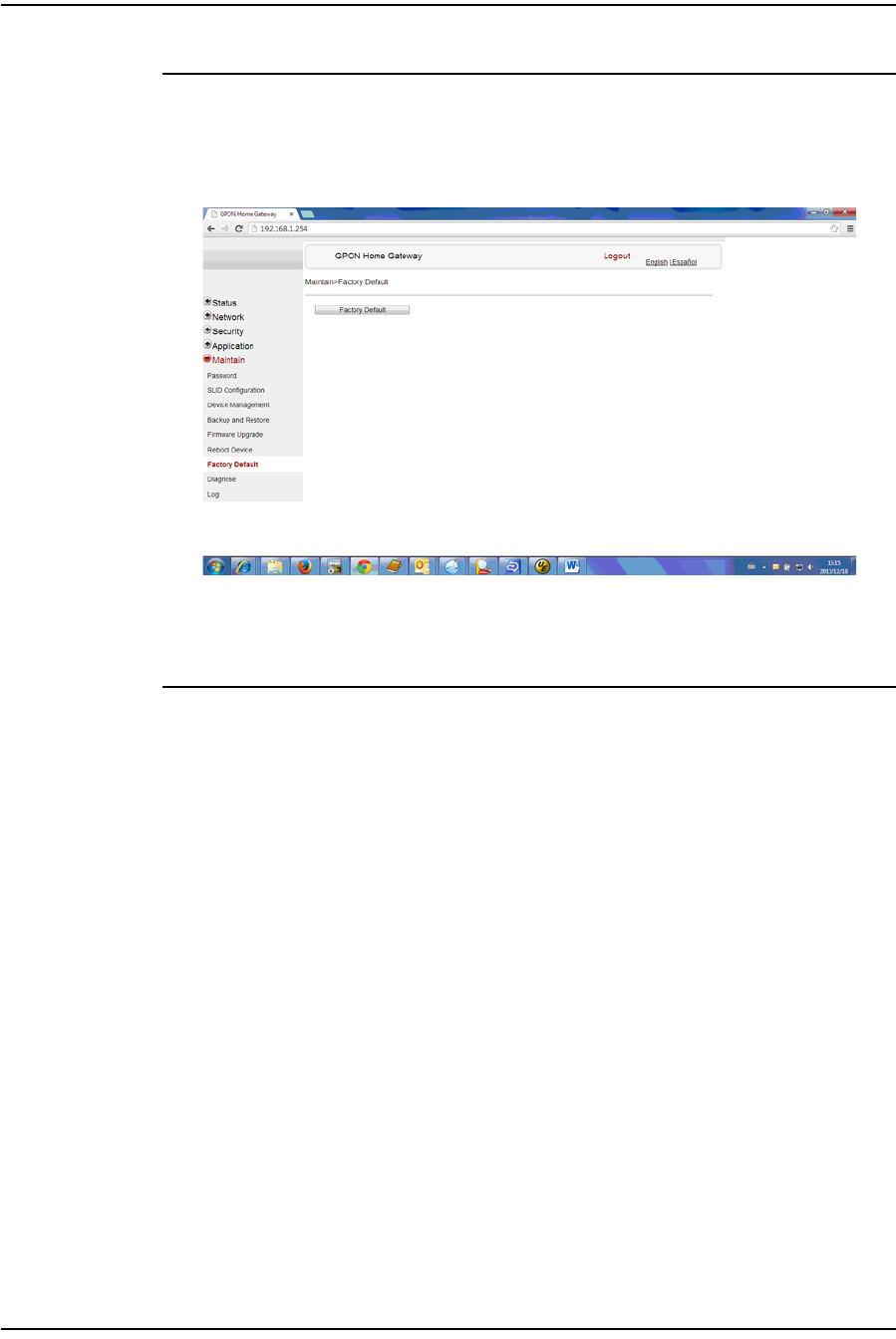
4 — Configure a G-241W-A indoor ONT
4-38 Alcatel-Lucent 7368 ISAM ONT
Edition 01
I-240W-S I-241W-S I-241W-U Product Guide
Procedure 4-33 Restore factory defaults
1Select Maintain > Factory Default from the top-level menu in the GPON Home
Gateway window, as shown in Figure 4-33.
Figure 4-33 Factory default window
2Click Factory Default to reset the ONT to its factory default settings.
3STOP. This procedure is complete.
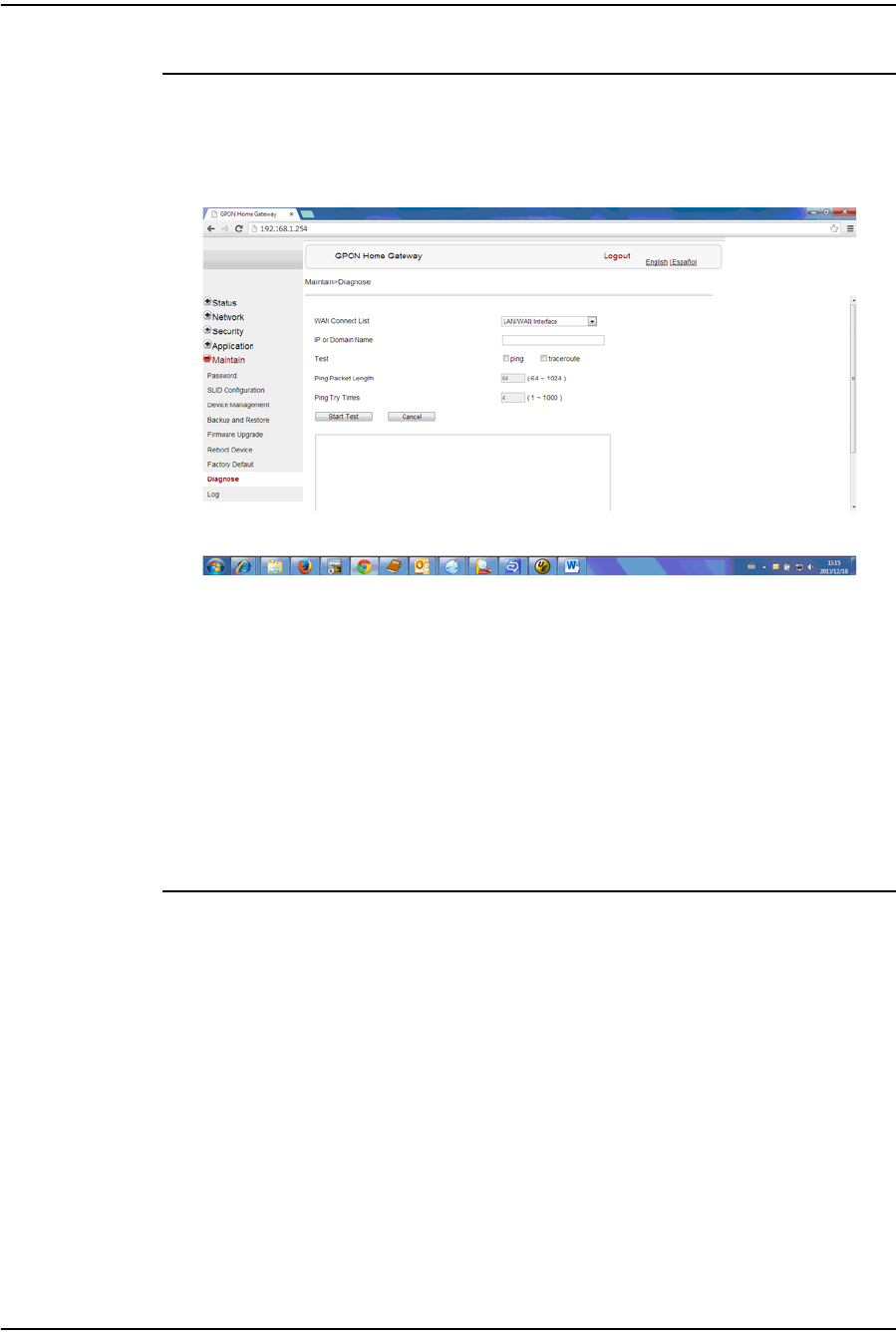
4 — Configure a G-241W-A indoor ONT
Alcatel-Lucent 7368 ISAM ONT 4-39
Edition 01
I-240W-S I-241W-S I-241W-U Product Guide
Procedure 4-34 Diagnose connections
1Select Maintain > Diagnose from the top-level menu in the GPON Home Gateway
window, as shown in Figure 4-34.
Figure 4-34 Diagnose window
2Choose a WAN connection to diagnose from the drop-down menu.
3Enter the IP address or domain name.
4Select the test type by selecting either ping or traceroute.
5Enter a ping packet length (64-1024).
6Enter the number of ping attempts to perform (1 - 1000).
7Click Start Test. Results will be displayed at the bottom of the window.
8STOP. This procedure is complete.
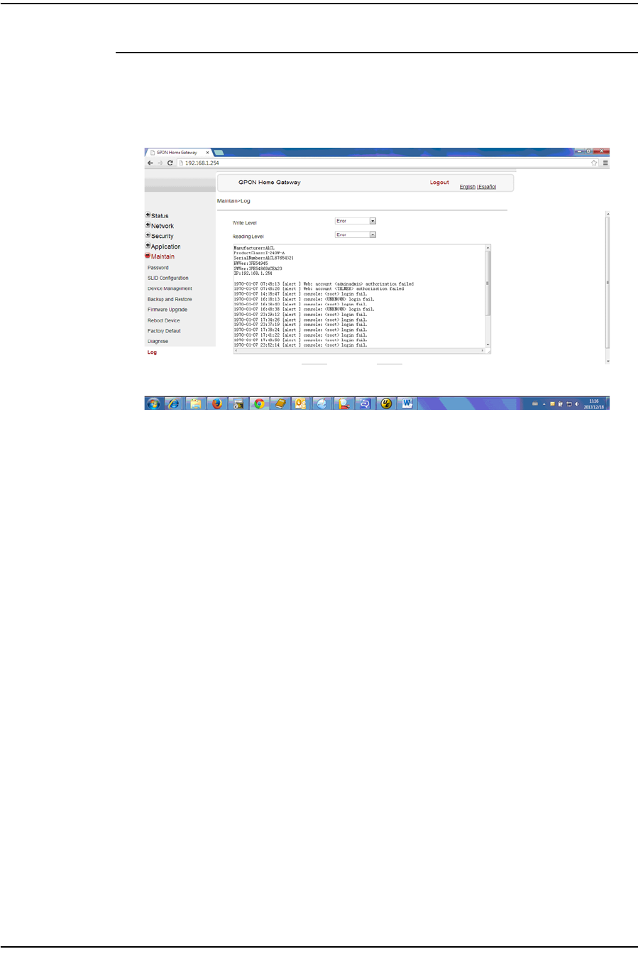
4 — Configure a G-241W-A indoor ONT
4-40 Alcatel-Lucent 7368 ISAM ONT
Edition 01
I-240W-S I-241W-S I-241W-U Product Guide
Procedure 4-35 View log files
1Select Maintain > Log from the top-level menu in the GPON Home Gateway
window, as shown in Figure 4-35.
Figure 4-35 Log window
2Choose a write level from the drop-down menu to determine which types of events
are recorded in the log file:
•Emergency
•Alert
•Critical
•Error
•Warning
•Notice
•Informational
•Debug
3Choose a reading level from the drop-down menu to determine which types of
events to display from the log file:
•Emergency
•Alert
•Critical
•Error
•Warning
•Notice
•Informational
•Debug
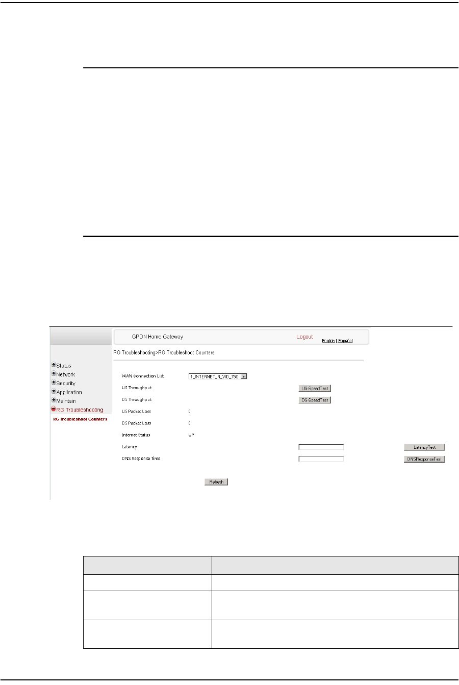
4 — Configure a G-241W-A indoor ONT
Alcatel-Lucent 7368 ISAM ONT 4-41
Edition 01
I-240W-S I-241W-S I-241W-U Product Guide
4The log file is displayed at the bottom of the window.
5STOP. This procedure is complete.
RG troubleshooting counters
The Troubleshooting Counters feature enables service providers and end users to
monitor the performance of their broadband connection.
Tests are run to retrieve upstream and downstream throughput, latency, and DNS
response time. The Troubleshooting Counters window also displays upstream and
downstream packet loss and Internet status.
Procedure 4-36 Retrieve Residential Gateway (RG) troubleshooting
counters
1Select RG Troubleshooting Counters from the left menu in the GPON Home
Gateway window.
The RG Troubleshooting Counters window appears; see Figure 4-36.
Figure 4-36 RG Troubleshooting Counters window
Table 4-28 describes the fields in the RG Troubleshooting Counters window.
Table 4-28 RG Troubleshooting Counters parameters
Field Description
WAN Connection List Select a WAN connection from the list
US Throughput Click US Speed Test to specify the time for the upstream test
The default is weekly, performed at idle to a public server
DS Throughput Click DS Speed Test to specify the time for the downstream test
The default is weekly, performed at idle to a public server
(1 of 2)

4 — Configure a G-241W-A indoor ONT
4-42 Alcatel-Lucent 7368 ISAM ONT
Edition 01
I-240W-S I-241W-S I-241W-U Product Guide
2Configure the test times if desired.
3Click Refresh to update the data.
4STOP. This procedure is complete.
4.3 SFU mode GUI configuration
Use the procedures below to use the web-based GUI for the G-241W-A in SFU
mode. This mode is preset at delivery.
SFU customer premise devices are designed for single indoor residential
applications. These ONTs address the demand for bandwidth intensive services, such
as high definition television (HDTV), video-on-demand (VOD) and online games.
The ONT can be configured to seamlessly deliver voice-over-IP and high speed
Internet access via a single fiber optic connection to the home.
Login
Use the procedure below to log in to the web-based GUI for the G-241W-A.
Procedure 4-37 Login to web-based GUI
1Open a web browser and enter the IP address of the ONT in the address bar.
The login window appears.
The default gateway IP address is http://192.168.1.254. You can connect to this
IP address using your web browser after connecting your PC to one of Ethernet
ports of the ONT. The static IP address of your PC must be in the same subnet as
the ONT.
2Enter your username and password in the Log in window, as shown in Figure 4-37.
The default username and password are printed on the ONT. The default
superuser username is adminGPON. Contact Alcatel-Lucent for the superuser
password.
US Packet Loss The number of upstream packages lost
DS Packet Loss The number of downstream packages lost
Internet Status Whether the broadband connections is active (UP) or not (DOWN)
Latency Click Latency Test to specify the time for the test
The default is weekly, performed at idle to a public server
DNS Response Time Click DNS Response Test to specify the time for the test
The default is weekly, performed at idle to a public server
Field Description
(2 of 2)
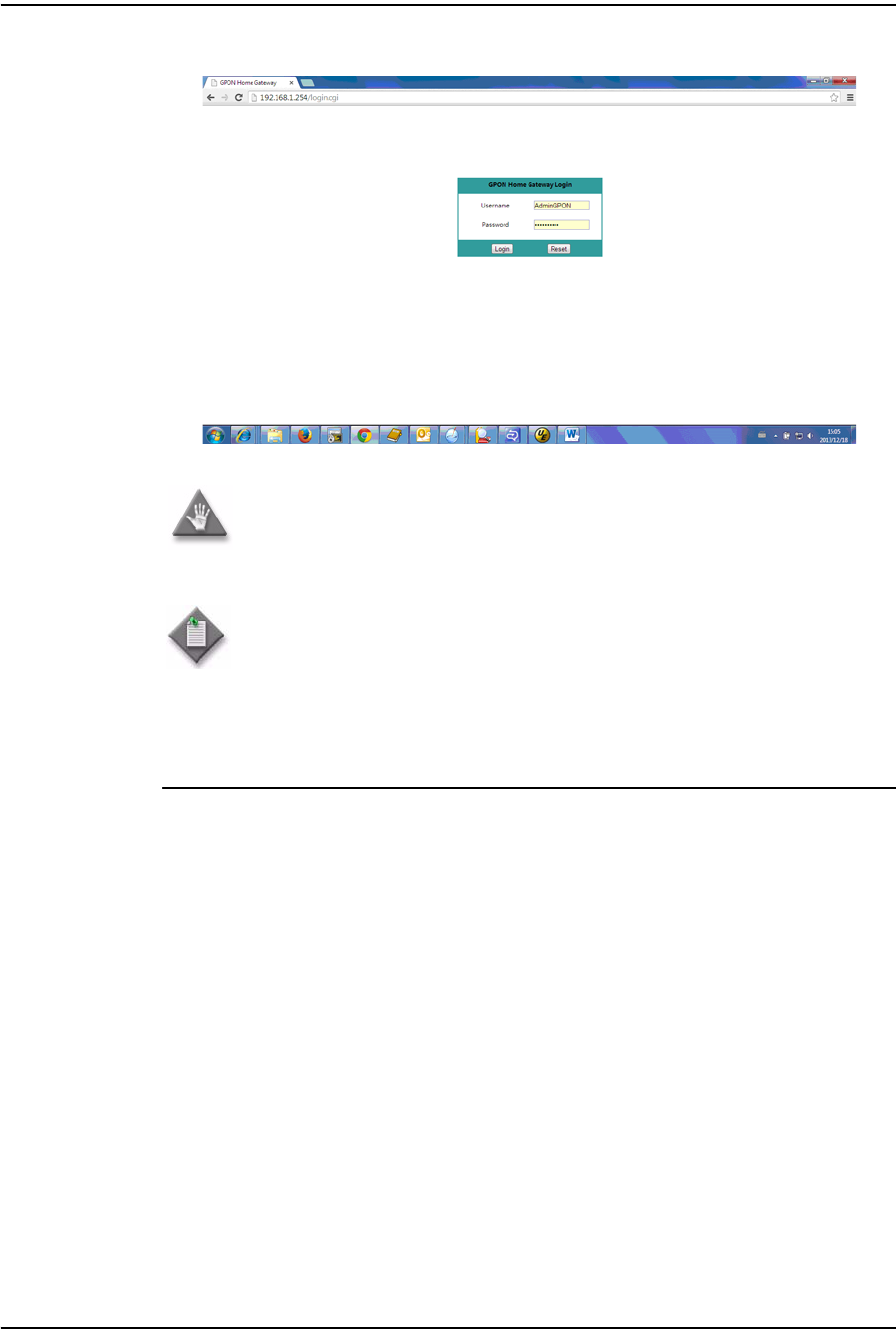
4 — Configure a G-241W-A indoor ONT
Alcatel-Lucent 7368 ISAM ONT 4-43
Edition 01
I-240W-S I-241W-S I-241W-U Product Guide
Figure 4-37 Web login window
3Click Login.
4STOP. This procedure is complete.
Device and connection status
G-241W-A ONTs support the retrieval of a variety of device information.
Caution — If you reset the router to recover the default username and
password, all other router configuration settings will also be restored to
their factory default values.
Note — If you forget the current username and password, press the
reset button for 5 s and the default values for the username and
password will be recovered at startup.
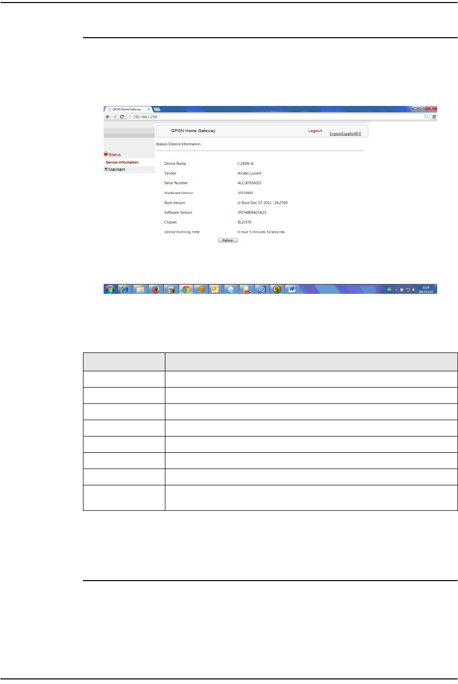
4 — Configure a G-241W-A indoor ONT
4-44 Alcatel-Lucent 7368 ISAM ONT
Edition 01
I-240W-S I-241W-S I-241W-U Product Guide
Procedure 4-38 Device information retrieval
1Select Status > Device Information from the top-level menu in the GPON Home
Gateway window, as shown in Figure 4-38.
Figure 4-38 Device Information window
Table 4-29 describes the fields in the Device Information window.
Table 4-29 Device Information parameters
2Click Refresh to update the displayed information.
3STOP. This procedure is complete.
Field Description
Device Name Name on the ONT
Vendor Name of the vendor
Serial Number Serial number of the ONT
Hardware version Hardware version of the ONT
Boot version Boot version of the ONT
Software version Software version of the ONT
Chipset Chipset of the ONT
Device Running
Time Amount of time the device has run since last reset in hours, minutes, and
seconds
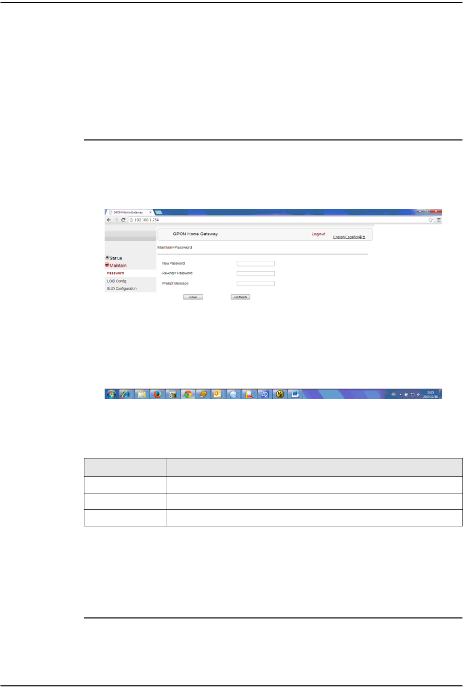
4 — Configure a G-241W-A indoor ONT
Alcatel-Lucent 7368 ISAM ONT 4-45
Edition 01
I-240W-S I-241W-S I-241W-U Product Guide
Maintenance
G-241W-A ONTs support maintenance tasks, including:
•password change
•LOID configuration
•SLID configuration
Procedure 4-39 Password configuration
1Select Maintain > Password from the top-level menu in the GPON Home Gateway
window, as shown in Figure 4-39.
Figure 4-39 Password window
Table 4-30 describes the fields in the password window.
Table 4-30 Password parameters
2Configure the new password.
3Click Save.
4STOP. This procedure is complete.
Field Description
New Password New password
Re-enter password Password must match password entered above
Prompt message Password prompt message

4 — Configure a G-241W-A indoor ONT
4-46 Alcatel-Lucent 7368 ISAM ONT
Edition 01
I-240W-S I-241W-S I-241W-U Product Guide
Procedure 4-40 LOID configuration
1Select Maintain > LOID Config from the top-level menu in the GPON Home Gateway
window, as shown in Figure 4-40.
Figure 4-40 LOID configuration window
2Enter the LOID.
3Enter the password, if applicable.
4Click Save/Apply.
5STOP. This procedure is complete.
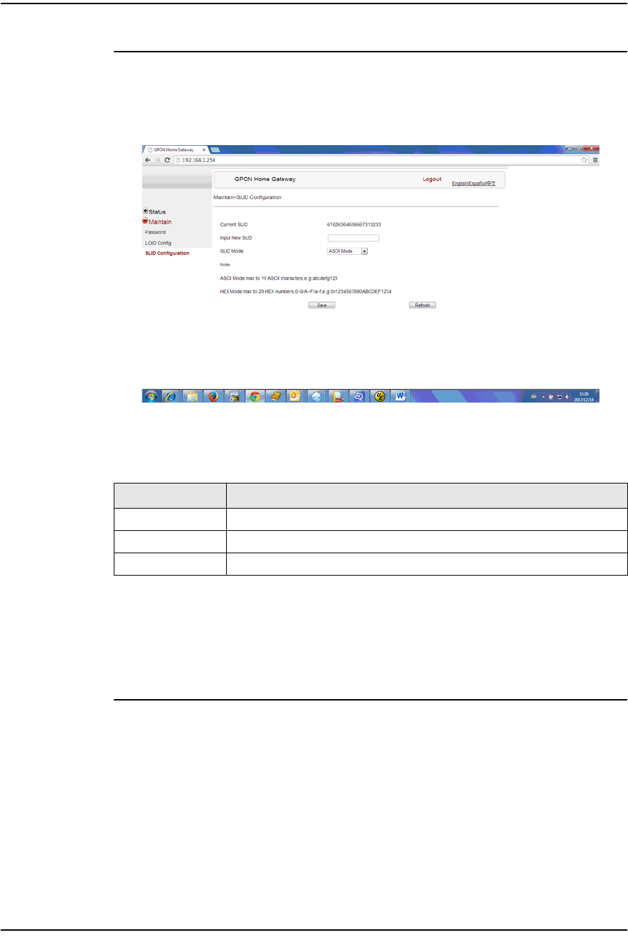
4 — Configure a G-241W-A indoor ONT
Alcatel-Lucent 7368 ISAM ONT 4-47
Edition 01
I-240W-S I-241W-S I-241W-U Product Guide
Procedure 4-41 SLID configuration
1Select Maintain > SLID Configuration from the top-level menu in the GPON Home
Gateway window, as shown in Figure 4-41.
Figure 4-41 SLID configuration window
Table 4-31 describes the fields in the SLID configuration window.
Table 4-31 SLID configuration parameters
2Configure the new SLID.
3Click Save.
4STOP. This procedure is complete.
4.4 Operator ID
Use the procedure below to modify the operator ID for the G-241W-A.
Field Description
Current SLID Displays current SLID
Input new SLID Enter new SLID
SLID Mode Choose a SLID mode from the drop-down menu.

4 — Configure a G-241W-A indoor ONT
4-48 Alcatel-Lucent 7368 ISAM ONT
Edition 01
I-240W-S I-241W-S I-241W-U Product Guide
Procedure 4-42 Modifying the operator ID
1Register the ONT with the OLT.
2Check the original OPID.
3Update the OntConfig.xml file by adding-the following content:
<OperatorObject version=”1.0”>
<OperatorID=”XXXX”>
</OperatorObject>
where: xxxx is the correct operator ID, for example ALCL for HGU mode, or XXXX for SFU mode.
4Use a TFTP client tool to transfer the OntConfi.xml file to the OLT’s ONT directory
and change the filename to the software version number, for example,
3FE123456789.xml.
5Use a TL1 command to configure ONUSWCRTL:
ENT-ONTSWCTRL::1::::HWVER=hwver,VARNT=,PLNDSWVER=UNPLANNED,
PLNDSWVERCONF=UNPLANNED,DLDSWVER=swver;
where:
hwver is the EQPTVERNUM, for example EQPTVERNUM=3FE54945ABAA.
swver is the software version number used as the filename in step 2, for example
3FE123456789.xml.
6Download the .xml file to update the operator ID:
ED-ONT::ONT-1/1/3/1/19::::DLSW=AUTO;
7Restart the ONT, then connect to the LAN and access the web-based GUI to check
the operator ID default setting.
8Use a TL1 command to disable further downloads:
ED-ONT::ONT-1/1/3/1/19::::DLSW=DISABLED;
9STOP. This procedure is complete.
Federal Communication Commission Interference
Statement
This equipment has been tested and found to comply with the limits for a Class B
digital device, pursuant to Part 15 of the FCC Rules. These limits are designed to
provide reasonable protection against harmful interference in a residential installation.
This equipment generates, uses and can radiate radio frequency energy and, if not
installed and used in accordance with the instructions, may cause harmful
interference to radio communications. However, there is no guarantee that
interference will not occur in a particular installation. If this equipment does cause
harmful interference to radio or television reception, which can be determined by
turning the equipment off and on, the user is encouraged to try to correct the
interference by one of the following measures:
z Reorient or relocate the receiving antenna.
z Increase the separation between the equipment and receiver.
z Connect the equipment into an outlet on a circuit different from that to which
the receiver is connected.
z Consult the dealer or an experienced radio/TV technician for help.
FCC Caution: Any changes or modifications not expressly approved by the party
responsible for compliance could void the user's authority to operate this equipment.
This device complies with Part 15 of the FCC Rules. Operation is subject to the
following two conditions: (1) This device may not cause harmful interference, and (2)
this device must accept any interference received, including interference that may
cause undesired operation.
IMPORTANT NOTE:
FCC Radiation Exposure Statement:
This equipment complies with FCC radiation exposure limits set forth for an
uncontrolled environment. This equipment should be installed and operated with
minimum distance 20cm between the radiator & your body.