Nokia Solutions and Networks FXCA-01 FXCA User Manual 2
Nokia Solutions and Networks FXCA Users Manual 2
Contents
- 1. Users Manual 1
- 2. Users Manual 2
- 3. Users Manual 3
- 4. Users Manual 4
Users Manual 2
Installing the plinth (continued)
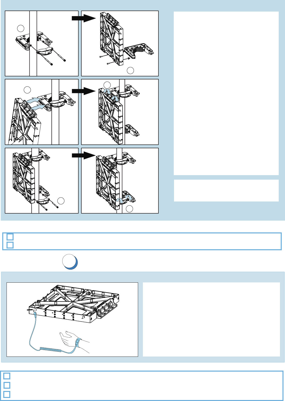
Plinth on the pole
Note that the length of mounting screws
depends on the diameter of the pole.
Please see the user manual for details.
(Note that installations is shown. See the user manual if the pole mounting kit is used.)FPKA VMPB
1. Fix the upper mounting bracket on
the pole. Attach the mounting bracket
screws (M10) on the bracket. Tighten
screws to 30 Nm.
2. Fix one side of the lower pole
mounting bracket on the plinth with
mounting screws (M8). Tighten
screws to 20 Nm.
3. Lift the plinth on the pole and fit it to
the mounting screws of the pole
mounting bracket. Tighten screws
(M8) to 20 Nm.
4. Place the counterpart of the lower
pole mounting bracket in its place.
Tighten screws (M10) to 30 Nm.
6. Ground the plinth to the site main
ground.
5. If a second plinth is required, install
it on the other side of the pole
mounting bracket.
3
6
1
30 Nm
5
30 Nm
2
20 Nm
4
20 Nm
Plinth is installed according to instructions.
Plinth is level.
Check list
Grounding principle
1. Ground the plinth to the site main
ground. Tighten to 8.0-10.0 Nm (5.9-7.37 ft-lb)
2. Connect the wrist strap.
to ESD stud
Wrist strap
Antistatic wrist strap is used when handling modules.
Check list
Plinth is grounded.
Local grounding (earthing) regulations are followed.
Grounding the plinth
4
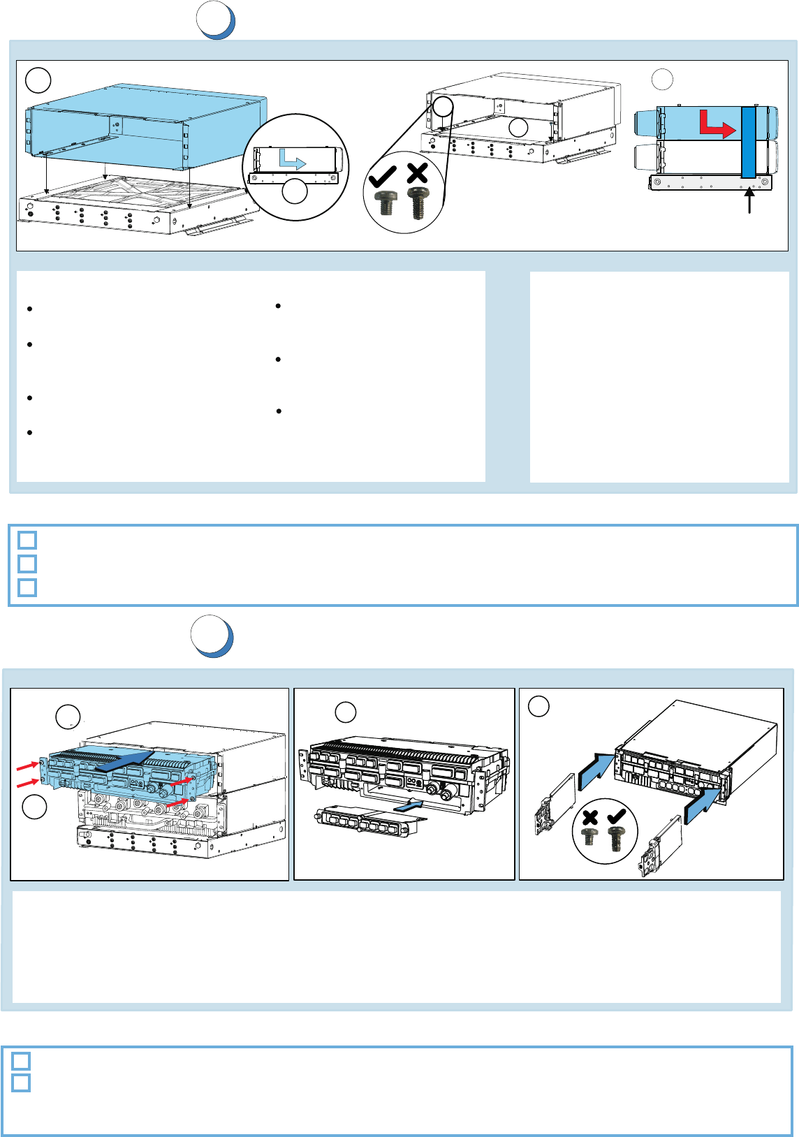
Installing the casings
5
1. Align the holes of the first casing
bottom with the fixing studs
on the plinth
2. Push the casing back until it stops.
3. Attach the casing to the plinth with
M5 X 8 mm screws (6150279).
Tighten to 3.5-4.2 Nm
(2.58-3.10 ft-Ib)
4. Install the remaining casings as
required by the configuration
Back covers are properly installed.
Fixing screws are tightened.
Check list
Note:
The casings are pre-installed
with back covers.
In Earthquake Zone 4, the
maximum number of modules
for stack installations is five.
In Earthquake Zone 2, the
maximum allowed height for
a stack is 22U.
In pole and wall installations,
the maximum modules per
plinth is two.
In pole and wall installations,
maintenance straps must be
installed in the casings.
M5 X 8 screws should be
secured with thread locking
compound in pole and wall
installations
Optional: In pole and wall installations, maintenance straps are installed in the front covers.
Module installation principle
3. Install the transmission sub-module to the System Module. Tighten to 2.7-3.3 Nm (1.99-2.43 ft-Ib).
1. Slide the RF module and the into the casings.System Module
2. Attach the module(s) to the casing with M5 X 25 mm screws. Tighten to 3.5-4.2 Nm (2.58-3.10 ft-Ib).
Installing the modules
Check list
Module back covers and cable entries are installed.
Screws are tightened to the specified torque value.
4. Install the cable entries on both casings with M5 X 10 mm screws (6150240). Torque 3.5 to 4.2 Nm.
Note: In pole and wall installations, install the maintenance strap for back covers.
1
2
3
9
4
1
2
3
In Earthquake Zone 4, install
side fixing plates on the casings.
Side fixing plates for
Earthquake Zone 4
4
Note: In pole and wall installations, screws are secured with thread locking compound.