Nokia Solutions and Networks FXCA-01 FXCA User Manual 4
Nokia Solutions and Networks FXCA Users Manual 4
Contents
- 1. Users Manual 1
- 2. Users Manual 2
- 3. Users Manual 3
- 4. Users Manual 4
Users Manual 4
Powering up and commissioning the BTS
9
1. Power up the site and check the LEDs.
2. Commission the BTS.
Check list
DC power cables are connected and the cable clamp is in place.
Connector seals are firmly in place.
All cables are connected according to the configuration.
BTS external cables or cables between the modules on different plinths are routed via
cable entries.
Connector seals are firmly in place.
1. Remove connector seal from OPT1 connector in ESMB/C.
2. Remove protective cap from optical transceiver and insert it into OPT1 in ESMB/C.
3. Route optical cable through cable entry.
4. Uncover the connector. Pull back the optical cable connector seal to uncover the
connector.
5. Remove protective plugs.
6. Clean connectors with 99% alcohol and swabs.
7. Connect optical cable to optical transceiver in ESMB/C.
8. Push connector seal firmly.
9. Repeat steps 1-8 to connect optical transceiver and optical cable to OPT1 of FXxx.
10.Ensure all connector seals are properly installed.
Note: For commissioning the BTS, see Commissioning Flexi Multiradio BTS GSM/EDGE document
and Quick Guide for Flexi Multiradio BTS GSM/EDGE Commissioning
To avoid cabling rework, check that the unit powers on before tying down the cables.
Removing modules with the pull-out tool
(for maintenance only)
11
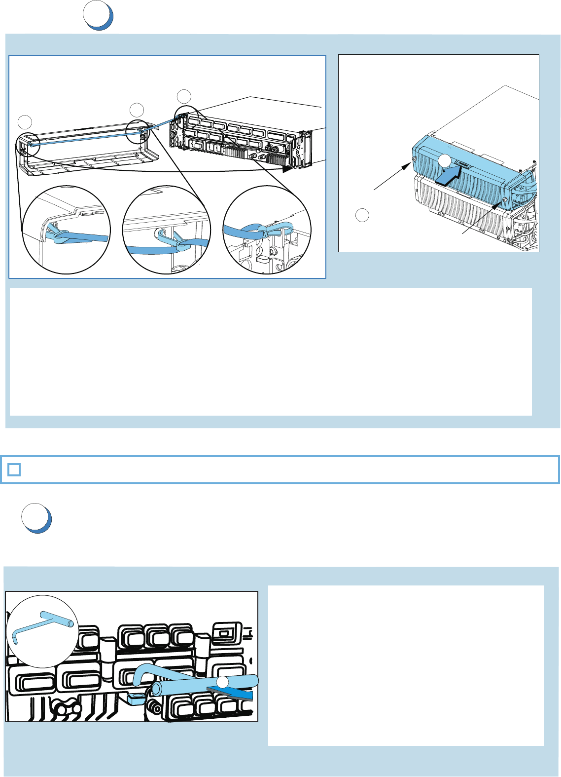
Installing module front covers
10
1. Fix the maintenance strap. (Pole or wall only)
Attach the first and second snap hooks of the maintenance strap to the front
cover.
Attach the third snap hook of the maintenance strap to the external cable entry.
2. Place the cover on top of the module front panel.
3. Fix the screws. Tighten the screws to
2.0 - 2.5 Nm (1.5-1.8 ft-Ib)
Module front panel covers are installed.
Check list
2
3
1
1
1
Module front covers
Maintenence strap
Caution:
1. Remove the front covers and cable entries.
2. Remove the module screws.
3. Hook the pull-out tool through the hole in
front of the module.
4. Pull until the unit comes loose.
Do not completely remove the module or
carry it with the pull-out tool.
Removing System Module with the pull-out tool
4
Pull-out tool
Installation check list
Perform these checks to make sure that the installation is complete:
Delivery is complete and undamaged.
Site meets the minimum clearances.
Plinth is installed according to the instructions.
Modules are installed according to the instructions.
External power cables are connected.
Antenna jumper cables are connected.
Transmission cables and sub-modules are connected.
Plinth is grounded.
One module per casing is grounded to the plinth.
Internal power cables are connected.
Optical cables are connected.
BTS external cables or cables between the modules on different plinths are routed
via cable entries.
All boots and caps are properly connected and IP-sealed.
Only IP65 class cables with seals provided by Nokia Siemens Networks are used.
Optional cables (EAC, Synchronization, Site support interface, FPA interface,
LMP cables, RF cables) are connected.
Module front covers are installed.
BTS is switched on and all units are ready.
Site is clean and installation completed.
Screws are tightened to the specified torque value.
Note: In pole and wall installations, screws are secured with thread locking compound.