Nokia Solutions and Networks FXCA-01 FXCA User Manual 3
Nokia Solutions and Networks FXCA Users Manual 3
Contents
- 1. Users Manual 1
- 2. Users Manual 2
- 3. Users Manual 3
- 4. Users Manual 4
Users Manual 3
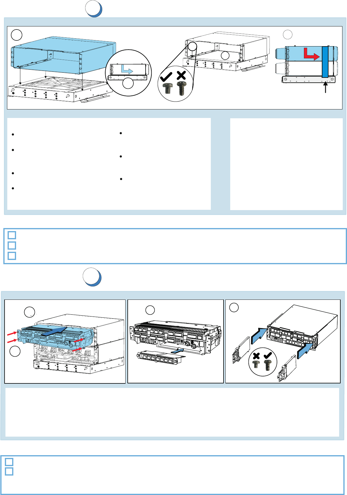
Installing the casings
5
1. Align the holes of the first casing
bottom with the fixing studs
on the plinth
2. Push the casing back until it stops.
3. Attach the casing to the plinth with
M5 X 8 mm screws (6150279).
Tighten to 3.5-4.2 Nm
(2.58-3.10 ft-Ib)
4. Install the remaining casings as
required by the configuration
Back covers are properly installed.
Fixing screws are tightened.
Check list
Note:
The casings are pre-installed
with back covers.
In Earthquake Zone 4, the
maximum number of modules
for stack installations is five.
In Earthquake Zone 2, the
maximum allowed height for
a stack is 22U.
In pole and wall installations,
the maximum modules per
plinth is two.
In pole and wall installations,
maintenance straps must be
installed in the casings.
M5 X 8 screws should be
secured with thread locking
compound in pole and wall
installations
Optional: In pole and wall installations, maintenance straps are installed in the front covers.
Module installation principle
3. Install the transmission sub-module to the System Module. Tighten to 2.7-3.3 Nm (1.99-2.43 ft-Ib).
1. Slide the RF module and the into the casings.System Module
2. Attach the module(s) to the casing with M5 X 25 mm screws. Tighten to 3.5-4.2 Nm (2.58-3.10 ft-Ib).
Installing the modules
Check list
Module back covers and cable entries are installed.
Screws are tightened to the specified torque value.
4. Install the cable entries on both casings with M5 X 10 mm screws (6150240). Torque 3.5 to 4.2 Nm.
Note: In pole and wall installations, install the maintenance strap for back covers.
1
2
3
9
4
1
2
3
In Earthquake Zone 4, install
side fixing plates on the casings.
Side fixing plates for
Earthquake Zone 4
4
Note: In pole and wall installations, screws are secured with thread locking compound.
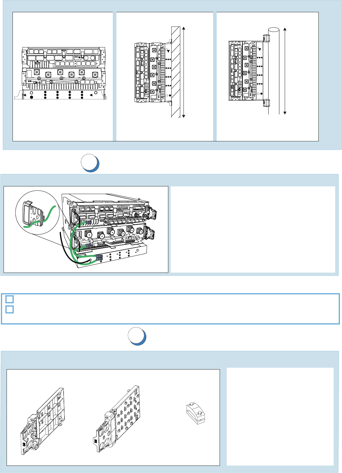
Grounding principle
Modules are grounded.
Check list
1. Connect the grounding cable to the module
front panel.
2. Route the grounding cable through the cable entry.
3. Connect the other end of the cable to the plinth.
4. Repeat steps 1-3 with all the modules.
Tighten to 3.5-4.2 Nm (2.58-3.10 ft-Ib).
Grounding the modules
1. Route the cables through
cable entries.
2. Fix to cable tie points with
cable ties.
Cable clamp
Cabling
Cable routing and cable ties
Cable entry
8
7
Ground
Antenna
Wall
Stack
Installation examples
Pole
Wall
Ground
Antenna
Pole
Cable Entry
Grounding connections are tightened to the correct torque values.
Caution: Incorrect cables
and seals may not provide
secured environmental
protection.Use only tested
IP65 class cables with seals
provided by Nokia Siemens
Networks.
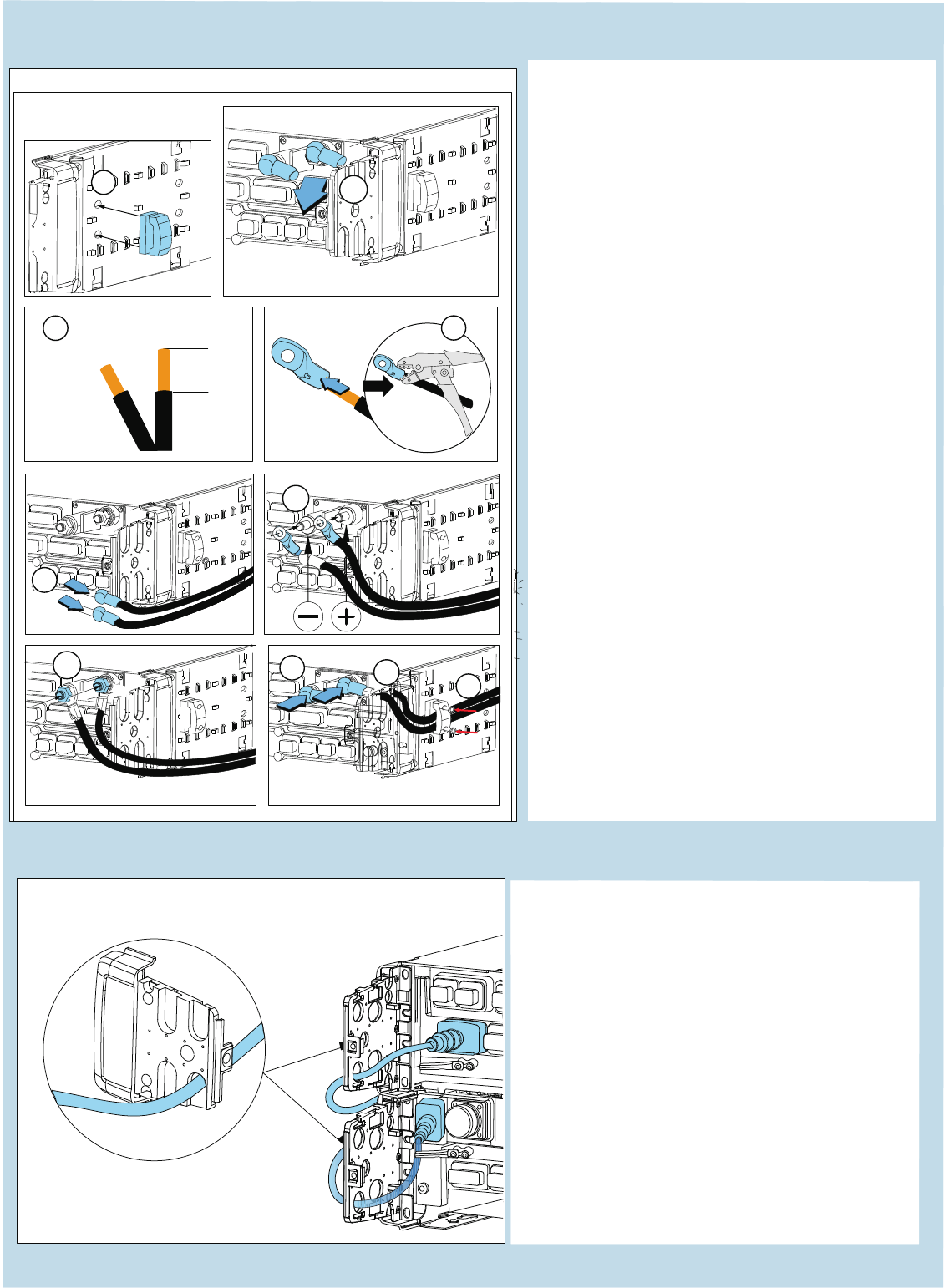
Connecting external power feed to system module
1. Install the cable clamp on the side of the
casing.
2. Remove the black rubber boots, nuts,
washers and cable lugs from the terminals.
3. Strip about 2 cm (.8 in) of insulation from
the (+) and (-) DC cables.
4. Insert the stripped end of each cable into
a cable lug and crimp.
5. Pull each cable through a rubber boot.
6a.Connect the (-) crimped wire to the
(-) connector pole, insert washer, and
tighten the nut. Connect the (+) crimped
wire to the (+) connector pole, insert
washer, and tighten the nut.
6b.Torque the M10 nuts (max 14 Nm).
7. Pull the black rubber boots over the lugs.
8. Route the cable through the external
cable entry.
9. Route the power cables through the
cable clamp, attach and tighten the cable
clamp screws with a T10 TORX
screwdriver.
Cabling (continued)
External power cables
1
2
cm
Cable
ends
Strip off about 2 cm
34
2
5
6a
789
6b
Internal power cables
1. Remove the connector seal on the
module to uncover the connector.
2. Connect the cable to the System
Module.
3. Push the connector seal firmly
in place.
4. Connect the other end of the internal
power cable to the RF Module.
Push the cable connector seal
firmly in place.
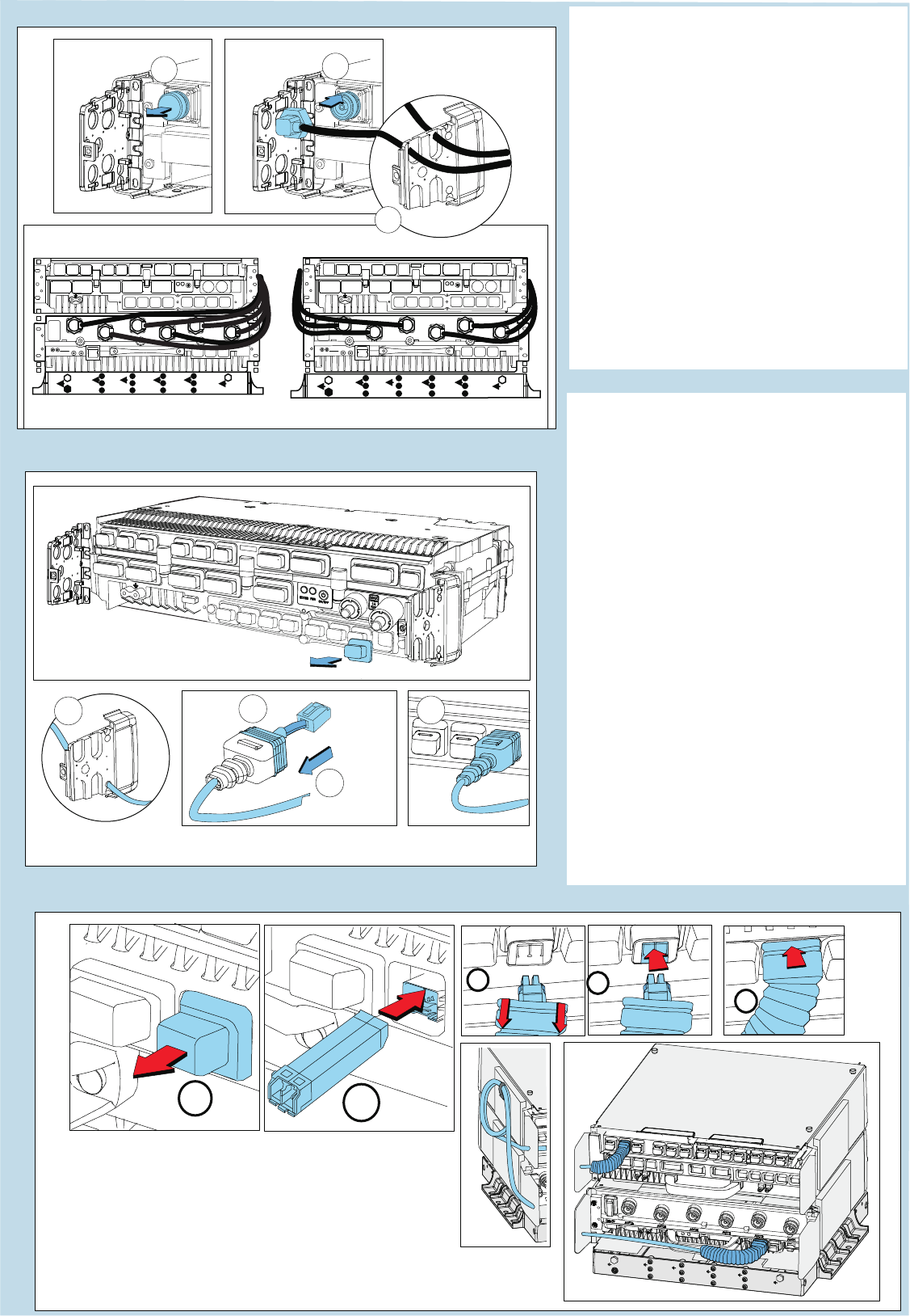
Antenna cabling 1. Remove seals from the antenna
connectors. Store the connector
seals for later use.
2. Connect the cable to the antenna
connectors.
3. Route the antenna cables through
the cable entry.
4. Tighten the connector with a torque
wrench set to 25 Nm.
5. Repeat the previous steps for all
antenna cables required for your
configuration.
2
3
1
Transmission cables
5
3
4
2
1. Remove the connector seal(s)
from the connector.
2. Route the cable through the cable
entry.
3. Pull back the connector seal
covering the cable (Flexbus
connector excluded).
4. Connect the cable to the
appropriate connector.
5. Push the cable connector seal
firmly in place.
6. Repeat the previous steps for all
cables.
7. Make sure the that all the
connector seals are properly
installed.
12
8
7
4
Left side
Caution: Overbending optical fiber cables
damages the cables and can detach or
damage the connectors. Do not bend
optical fiber cables to a radius smaller
than the minimum radius of 70 mm (3 inches).
Optical cabling