Nokia Solutions and Networks FZCWM2A1 Wi-Fi AP Module 802.11 ac User Manual Pico Dual Band QG draft RMP

Nokia Solutions and Networks, OY Wi-Fi AP Module 802.11 ac Pico Dual Band QG draft RMP

User Manual (System)

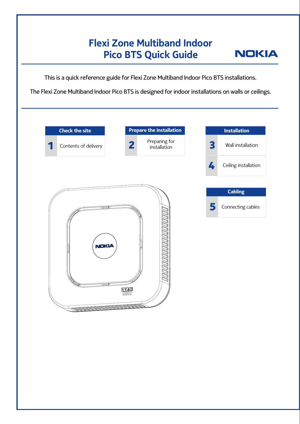
Flexi Zone Multiband Indoor  Pico BTS Quick GuideThis is a quick reference guide for Flexi Zone Multiband Indoor Pico BTS installations.The Flexi Zone Multiband Indoor Pico BTS is designed for indoor installations on walls or ceilings. Prepare the installationPreparing for installation2Check the site1Contents of deliveryWall installationCeiling installationInstallation34CablingConnecting cables5
The information in this document applies solely to the hardware/software product (“Product”) specified herein, and only as specified herein. This document is intended for use by Nokia Solutions and Networks' customers (“You”) only, and it may not be used except for the purposes defined in the agreement between You and Nokia Solutions and Networks (“Agreement”) under which this document is distributed. No part of this document may be used, copied, reproduced, modified or transmitted in any form or means without the prior written permission of Nokia Solutions and Networks. If you have not entered into an Agreement applicable to the Product, or if that Agreement has expired or has been terminated, You may not use this document in any manner and You are obliged to return it to Nokia Solutions and Networks and destroy or delete any copies thereof.The document has been prepared to be used by professional and properly trained personnel, and You assume full responsibility when using it. Nokia Solutions and Networks welcome Your comments as part of the process of continuous development and improvement of the documentation. This document and its contents are provided as a convenience to You. Any information or statements concerning the suitability, capacity, fitness for purpose or performance of the Product are given solely on an “as is” and “as available” basis in this document, and Nokia Solutions and Networks reserves the right to change any such information and statements without notice. Nokia has made all reasonable efforts to ensure that the content of this document is adequate and free of material errors and omissions, and Nokia Solutions and Networks will correct errors that You identify in this document. But, Nokia Solutions and Networks' total liability for any errors in the document is strictly limited to the correction of such error(s). Nokia Solutions and Networks does not warrant that the use of the software in the Product will be uninterrupted or error-free.NO WARRANTY OF ANY KIND, EITHER EXPRESS OR IMPLIED, INCLUDING BUT NOT LIMITED TO ANY WARRANTY OF AVAILABILITY, ACCURACY, RELIABILITY, TITLE, NON-INFRINGEMENT, MERCHANTABILITY OR FITNESS FOR A PARTICULAR PURPOSE, IS MADE IN RELATION TO THE CONTENT OF THIS DOCUMENT. IN NO EVENT WILL NOKIA SOLUTIONS AND NETWORKS BE LIABLE FOR ANY DAMAGES, INCLUDING BUT NOT LIMITED TO SPECIAL, DIRECT, INDIRECT, INCIDENTAL OR CONSEQUENTIAL OR ANY LOSSES, SUCH AS BUT NOT LIMITED TO LOSS OF PROFIT, REVENUE, BUSINESS INTERRUPTION, BUSINESS OPPORTUNITY OR DATA THAT MAY ARISE FROM THE USE OF THIS DOCUMENT OR THE INFORMATION IN IT, EVEN IN THE CASE OF ERRORS IN OR OMISSIONS FROM THIS DOCUMENT OR ITS CONTENT.This document is Nokia Solutions and Networks’ proprietary and confidential information, which may not be distributed or disclosed to any third parties without the prior written consent of Nokia Solutions and Networks.Nokia is a registered trademark of Nokia Corporation. Other product names mentioned in this document may be trademarks of their respective owners, and they are mentioned for identification purposes only.Copyright © 2016 Nokia Solutions and Networks. All rights reserved.Important Notice on Product SafetyThis product may present safety risks due to laser, electricity, heat, and other sources of danger.Only trained and qualified personnel may install, operate, maintain or otherwise handle this product and only after having carefully read the safety information applicable to this product.The safety information is provided in the Safety Information section in the “Legal, Safety and Environmental Information” part of this document or documentation set.Nokia Solutions and Networks is continually striving to reduce the adverse environmental effects of its products and services. We would like to encourage you as our customers and users to join us in working towards a cleaner, safer environment. Please recycle product packaging and follow the recommendations for power use and proper disposal of our products and their components.If you should have questions regarding our Environmental Policy or any of the environmental services we offer, please contact us at Nokia Solutions and Networks for any additional information.DN09218794, Issue 03, Approval date: 2016-04-22    -2-Federal Communication Commission Interference StatementThis device complies with Part 15 of the FCC Rules. Operation is subject to the following two conditions: (1) This device does not cause harmfulinterference, and (2) this device must accept any interference received, including interference that may cause undesired operation.This equipment has been tested and complies with the Class B digital device limits, pursuant to Part 15 of the FCC Rules.  Theselimits are designed to provide reasonable protection against harmful interference in a residential installation. This equipment generates, usesand can radiate radio frequency energy and, if not installed and used according to the instructions, may cause harmful interference toradio communications.  However, there is no guarantee that interference cannot  occur in a particular installation. If this equipment doescause harmful interference to radio or television reception, which can be determined by turning the equipment off and on, the user isencouraged to try to correct the interference by taking one of the following actions:· Reorient or relocate the receiving antenna.· Increase the separation between the equipment and the receiver.· Connect the equipment into an outlet on a circuit different from that to which the receiver is connected.· Consult the dealer or an experienced radio/TV technician for help.FCC Caution Any changes or modifications not expressly approved by the party responsible for compliance could void the user's authorityto operate this equipment.RF Modules installed in this product must not be co-located or operating in conjunction with any other antenna or transmitters, except when installed in accordance with FCC multi-transmitter product guidelines..Operation within the 5.15 ~ 5.25 GHz / 5.47 ~5.725 GHz frequency ranges are restricted to indoor environment. The band from 5600-5650 MHz is disabled by the software during manufacturing and cannot be changed by the end user. This device meets all other requirements specified in Part 15E, Section 15.407 of the FCC Rules.FCC Radiation Exposure StatementThis equipment complies with FCC radiation exposure limits set forth for an uncontrolled environments. This equipment should be installedand operated in accordance with the minimum distance Compliance Boundaries table located on Page 3.Federal Communication Commission Interference StatementFCC CautionRadiation Exposure StatementFCC
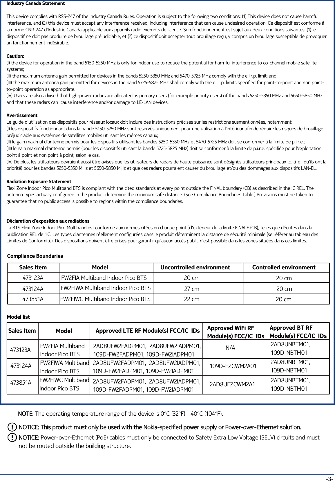
-3-Industry Canada StatementThis device complies with RSS-247 of the Industry Canada Rules. Operation is subject to the following two conditions: (1) This device does not cause harmful interference, and (2) this device must accept any interference received, including interference that can cause undesired operation. Ce dispositif est conforme à la norme CNR-247 d'Industrie Canada applicable aux appareils radio exempts de licence. Son fonctionnement est sujet aux deux conditions suivantes: (1) le dispositif ne doit pas produire de brouillage préjudiciable, et (2) ce dispositif doit accepter tout brouillage reçu, y compris un brouillage susceptible de provoquer un fonctionnement indésirable. Caution:(I) the device for operation in the band 5150-5250 MHz is only for indoor use to reduce the potential for harmful interference to co-channel mobile satellite systems;(II) the maximum antenna gain permitted for devices in the bands 5250-5350 MHz and 5470-5725 MHz comply with the e.i.r.p. limit; and(III) the maximum antenna gain permitted for devices in the band 5725-5825 MHz shall comply with the e.i.r.p. limits specified for point-to-point and non point-to-point operation as appropriate.(IV) Users are also advised that high-power radars are allocated as primary users (for example priority users) of the bands 5250-5350 MHz and 5650-5850 MHz and that these radars can  cause interference and/or damage to LE-LAN devices.AvertissementLe guide d'utilisation des dispositifs pour réseaux locaux doit inclure des instructions précises sur les restrictions susmentionnées, notamment:(I) les dispositifs fonctionnant dans la bande 5150-5250 MHz sont réservés uniquement pour une utilisation à l'intérieur afin de réduire les risques de brouillage préjudiciable aux systèmes de satellites mobiles utilisant les mêmes canaux;(II) le gain maximal d'antenne permis pour les dispositifs utilisant les bandes 5250-5350 MHz et 5470-5725 MHz doit se conformer à la limite de p.i.r.e.;(III) le gain maximal d'antenne permis (pour les dispositifs utilisant la bande 5725-5825 MHz) doit se conformer à la limite de p.i.r.e. spécifiée pour l'exploitation point à point et non point à point, selon le cas.(IV) De plus, les utilisateurs devraient aussi être avisés que les utilisateurs de radars de haute puissance sont désignés utilisateurs principaux (c.-à-d., qu'ils ont la priorité) pour les bandes 5250-5350 MHz et 5650-5850 MHz et que ces radars pourraient causer du brouillage et/ou des dommages aux dispositifs LAN-EL.Radiation Exposure StatementFlexi Zone Indoor Pico Mulitband BTS is compliant with the cited standards at every point outside the FINAL boundary (CB) as described in the IC REL. The antenna types actually configured in the product determine the minimum safe distance. (See Compliance Boundaries Table.) Provisions must be taken to guarantee that no public access is possible to regions within the compliance boundaries.Déclaration d’exposition aux radiationsLa BTS Flexi Zone Indoor Pico Multiband est conforme aux normes citées en chaque point à l'extérieur de la limite FINALE (CB), telles que décrites dans la publication REL de l'IC. Les types d'antennes réellement configurées dans le produit déterminent la distance de sécurité minimale (se référer au tableau des Limites de Conformité). Des dispositions doivent être prises pour garantir qu'aucun accès public n'est possible dans les zones situées dans ces limites.NOTE: The operating temperature range of the device is 0°C (32°F) - 40°C (104°F).NOTE:Model listSales Item Model Approved LTE RF Module(s) FCC/IC  IDs2AD8UFW2FADPM01,  2AD8UFW2IADPM01,109D-FW2FADPM01, 109D-FW2IADPM012AD8UNBTM01, 109D-NBTM012AD8UFW2FADPM01,  2AD8UFW2IADPM01, 109D-FW2FADPM01, 109D-FW2IADPM012AD8UNBTM01, 109D-NBTM01FW2FIA MultibandIndoor Pico BTS FW2FIWA Multiband Indoor Pico BTS 473123A473124ANOTICE: This product must only be used with the Nokia-specified power supply or Power-over-Ethernet solution.NOTICE: This product must only be used with the Nokia-specified power supply or Power-over-Ethernet solution.NOTICE: Power-over-Ethernet (PoE) cables must only be connected to Safety Extra Low Voltage (SELV) circuits and must not be routed outside the building structure.NOTICE:Compliance BoundariesSales Item Model Uncontrolled environment20 cm27 cmFW2FIA Multiband Indoor Pico BTS FW2FIWA Multiband Indoor Pico BTS 473123A473124A473851A FW2FIWC Multiband Indoor Pico BTS Controlled environment22 cm20 cm20 cm20 cmApproved WiFi RF Module(s) FCC/IC  IDsApproved BT RF Module(s) FCC/IC  IDsN/A109D-FZCWM2A01 473851A FW2FIWC Multiband Indoor Pico BTS 2AD8UFZCWM2A1 2AD8UFW2FADPM01,  2AD8UFW2IADPM01,109D-FW2FADPM01, 109D-FW2IADPM012AD8UNBTM01, 109D-NBTM01
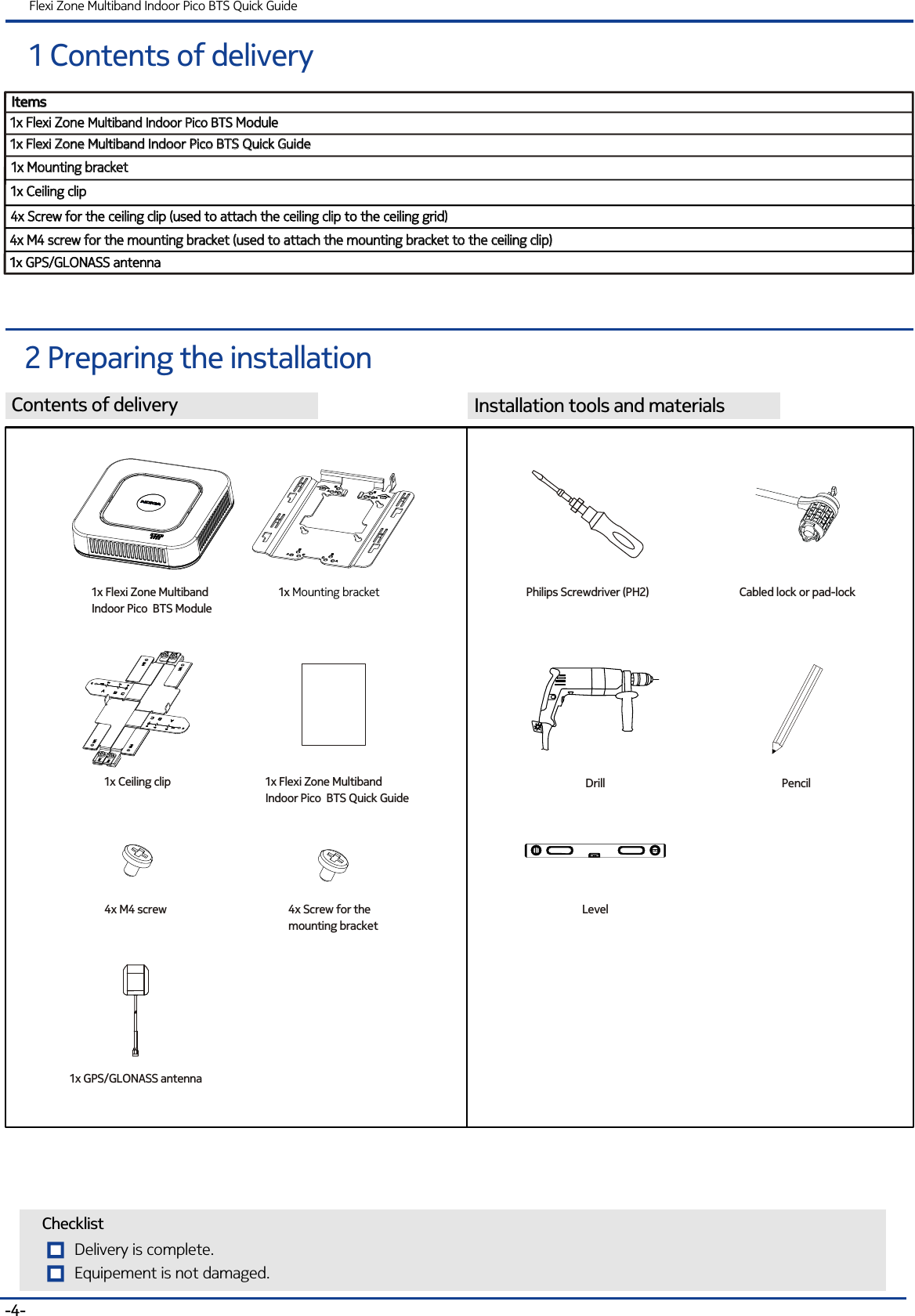
Contents of deliveryItemsItems1x Flexi Zone Multiband Indoor Pico BTS Module1x Flexi Zone  ModuleMultiband Indoor Pico BTS 1x Ceiling clip1x Ceiling clip1 Contents of deliveryFlexi Zone Multiband Indoor Pico BTS Quick Guide2 Preparing the installationInstallation tools and materials-4-1x Flexi Zone Multiband Indoor Pico BTS Quick Guide1x Flexi Zone Multiband Indoor Pico BTS Quick Guide1x Mounting bracket1x Mounting bracket1x Flexi Zone MultibandIndoor Pico  BTS Quick Guide1x Ceiling clip1x Mounting bracket Delivery is complete.ChecklistEquipement is not damaged. 1x Flexi Zone MultibandIndoor Pico  BTS Module4x M4 screw 4x Screw for the ceiling clip (used to attach the ceiling clip to the ceiling grid)4x Screw for the ceiling clip (used to attach the ceiling clip to the ceiling grid)4x M4 screw for the mounting bracket (used to attach the mounting bracket to the ceiling clip)4x M4 screw for the mounting bracket (used to attach the mounting bracket to the ceiling clip)4x Screw for the mounting bracketLevelPhilips Screwdriver (PH2)DrillCabled lock or pad-lockPencil1x GPS/GLONASS antenna1x GPS/GLONASS antenna1x GPS/GLONASS antenna
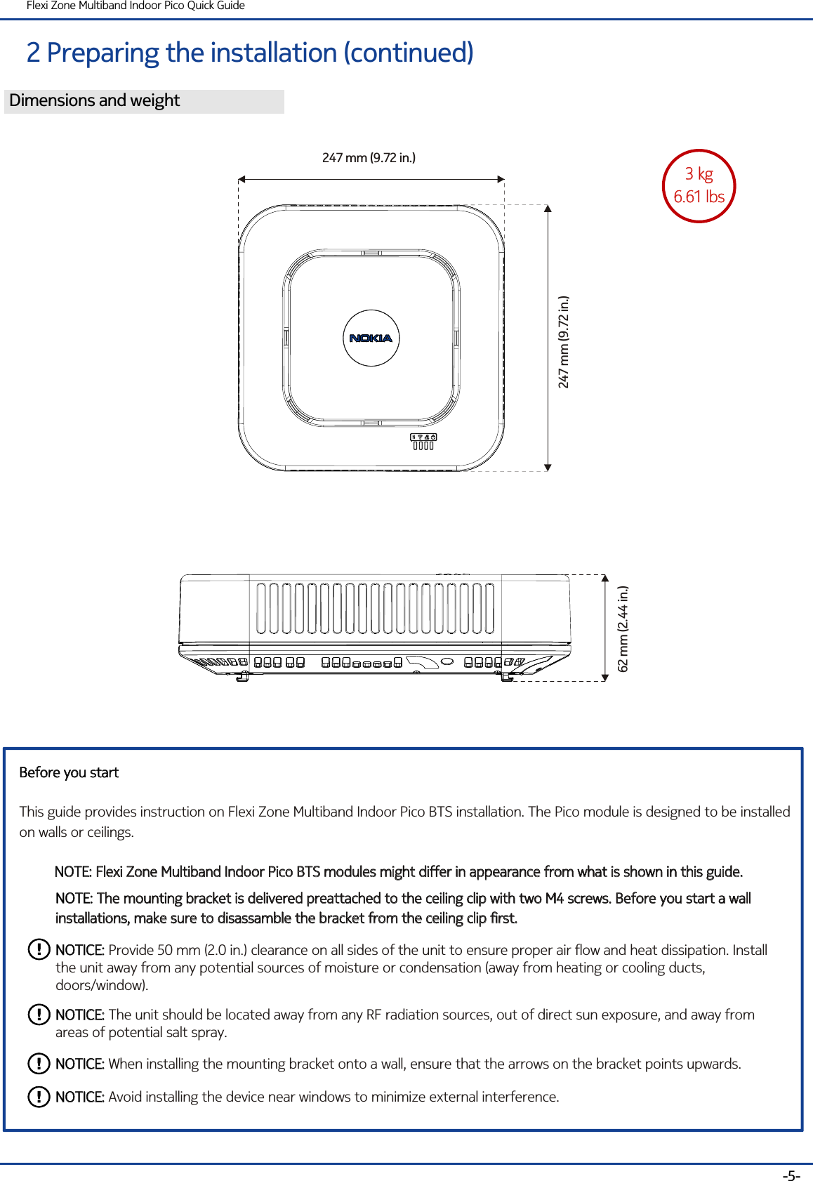
2 Preparing the installation (continued)Flexi Zone Multiband Indoor Pico Quick Guide-5-Dimensions and weight3 kg6.61 lbs3 kg6.61 lbs62 mm (2.44 in.)247 mm (9.72 in.)247 mm (9.72 in.)Before you startThis guide provides instruction on Flexi Zone Multiband Indoor Pico BTS installation. The Pico module is designed to be installedon walls or ceilings.Before you startNOTE: Flexi Zone Multiband Indoor Pico BTS modules might differ in appearance from what is shown in this guide. NOTE: Flexi Zone Multiband Indoor Pico BTS modules might differ in appearance from what is shown in this guide. NOTE: The mounting bracket is delivered preattached to the ceiling clip with two M4 screws. Before you start a wall installations, make sure to disassamble the bracket from the ceiling clip first.NOTE: The mounting bracket is delivered preattached to the ceiling clip with two M4 screws. Before you start a wall installations, make sure to disassamble the bracket from the ceiling clip first.NOTICE: Provide 50 mm (2.0 in.) clearance on all sides of the unit to ensure proper air flow and heat dissipation. Install the unit away from any potential sources of moisture or condensation (away from heating or cooling ducts, doors/window). NOTICE:NOTICE: The unit should be located away from any RF radiation sources, out of direct sun exposure, and away from areas of potential salt spray.NOTICE:NOTICE: When installing the mounting bracket onto a wall, ensure that the arrows on the bracket points upwards.NOTICE:NOTICE: Avoid installing the device near windows to minimize external interference.NOTICE:
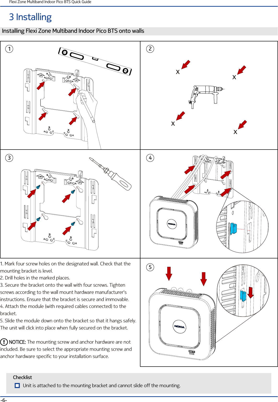
3 InstallingFlexi Zone Multiband Indoor Pico BTS Quick GuideChecklistInstalling Flexi Zone Multiband Indoor Pico BTS onto walls1. 2. 3. Mark four screw holes on the designated wall. Check that the mounting bracket is level.Drill holes in the marked places.Secure the bracket onto the wall with four screws. Tighten  screws according to the wall mount hardware manufacturer's instructions. Ensure that the bracket is secure and immovable.4. Attach the module (with required cables connected) to the bracket.5. Slide the module down onto the bracket so that it hangs safely. The unit will click into place when fully secured on the bracket.         The mounting screw and anchor hardware are not included. Be sure to select the appropriate mounting screw and anchor hardware specific to your installation surface.NOTICE:       NOTICE:-6-12435xxxxUnit is attached to the mounting bracket and cannot slide off the mounting.
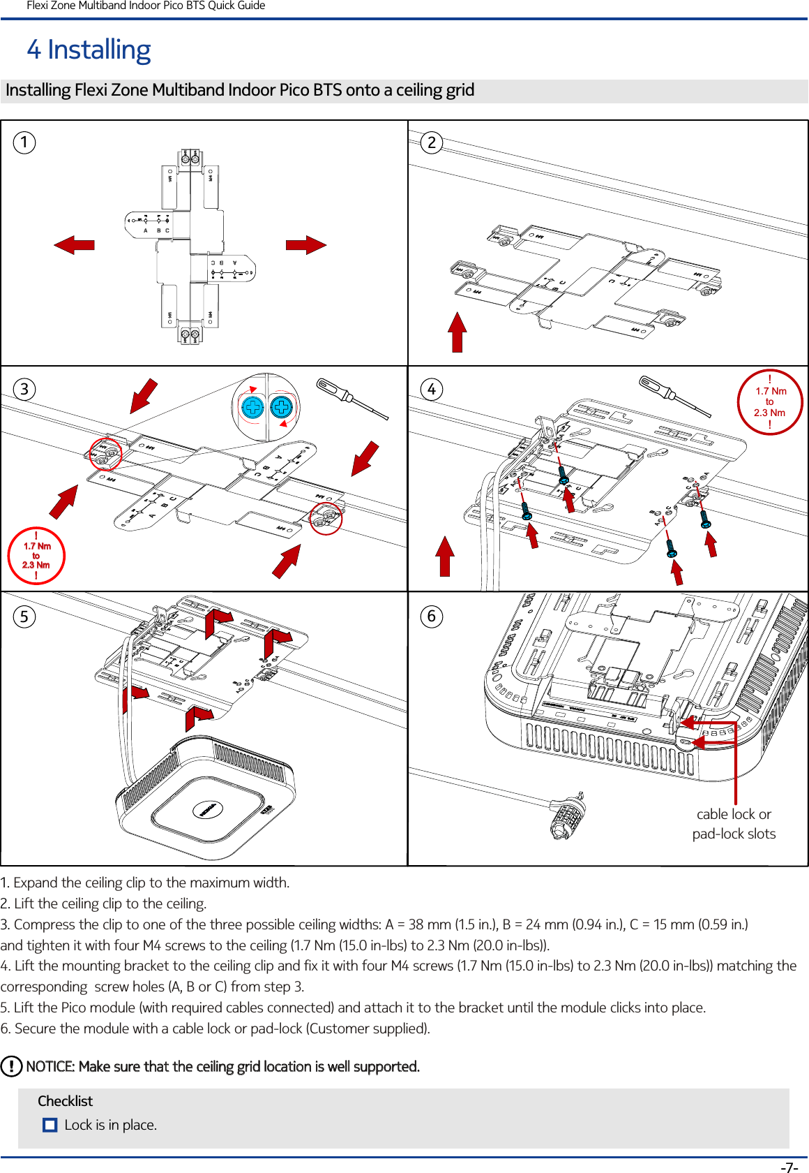
4 InstallingFlexi Zone Multiband Indoor Pico BTS Quick GuideChecklistInstalling Flexi Zone Multiband Indoor Pico BTS onto a ceiling grid1. 2. 3. Expand the ceiling clip to the maximum width.Lift the ceiling clip to the ceiling.Compress the clip to one of the three possible ceiling widths: A = 38 mm (1.5 in.), B = 24 mm (0.94 in.), C = 15 mm (0.59 in.)     and tighten it with four M4 screws to the ceiling (1.7 Nm (15.0 in-lbs) to 2.3 Nm (20.0 in-lbs)).4. Lift the mounting bracket to the ceiling clip and fix it with four M4 screws (1.7 Nm (15.0 in-lbs) to 2.3 Nm (20.0 in-lbs)) matching the corresponding  screw holes (A, B or C) from step 3.5. Lift the Pico module (with required cables connected) and attach it to the bracket until the module clicks into place. 6. Secure the module with a cable lock or pad-lock (Customer supplied).-7-132NOTICE: Make sure that the ceiling grid location is well supported.NOTICE: Make sure that the ceiling grid location is well supported.456cable lock orpad-lock slots! 1.7 Nm to 2.3 Nm!! 1.7 Nm to 2.3 Nm!!! 1.7 Nm to 2.3 NmLock is in place.
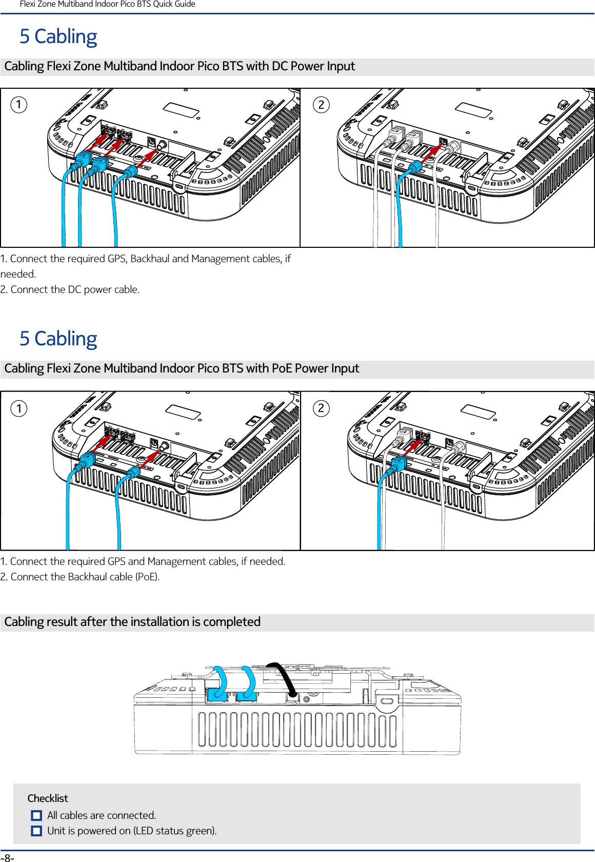
1. C2. onnect the required GPS, Backhaul and Management cables, if needed. Connect the DC power cable.Cabling Flexi Zone Multiband Indoor Pico BTS with DC Power InputFlexi Zone Multiband Indoor Pico BTS Quick Guide5 Cabling-8-125 CablingCabling Flexi Zone Multiband Indoor Pico BTS with PoE Power Input1. 2. Connect the required GPS and Management cables, if needed.Connect the Backhaul cable (PoE).ChecklistAll cables are connected.Unit is powered on (LED status green).Cabling result after the installation is completed21

Navigation menu