Nokia Solutions and Networks INLITERU-01 InLite Dual Band Enhancer Remote Unit User Manual System Requirements
Nokia Solutions and Networks InLite Dual Band Enhancer Remote Unit System Requirements
UserManual.wiki
>
Nokia Solutions and Networks
>
INLITERU-01 User Manual
>
System Requirements
Contents
1.
Alarm Description
2.
Maintenance
3.
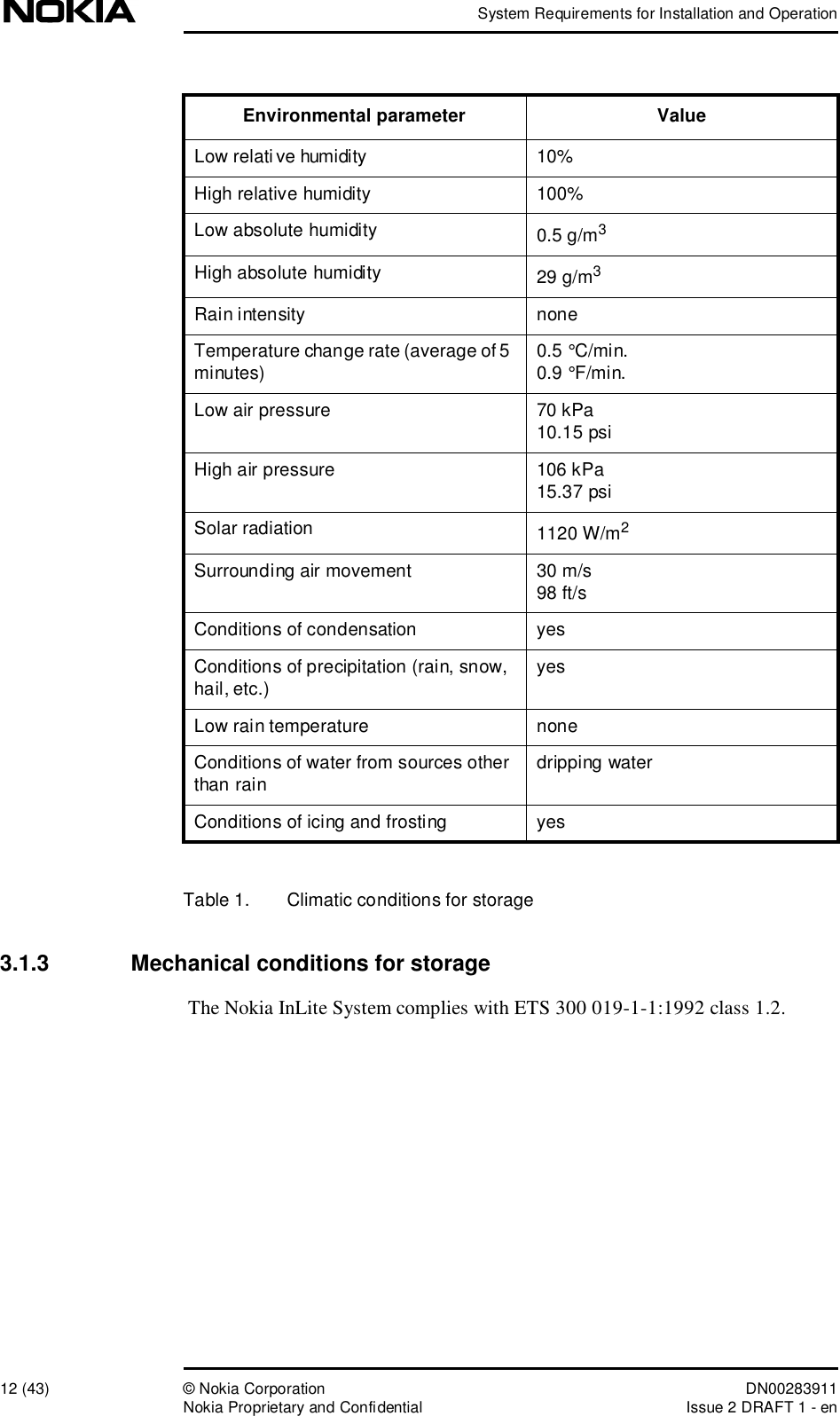
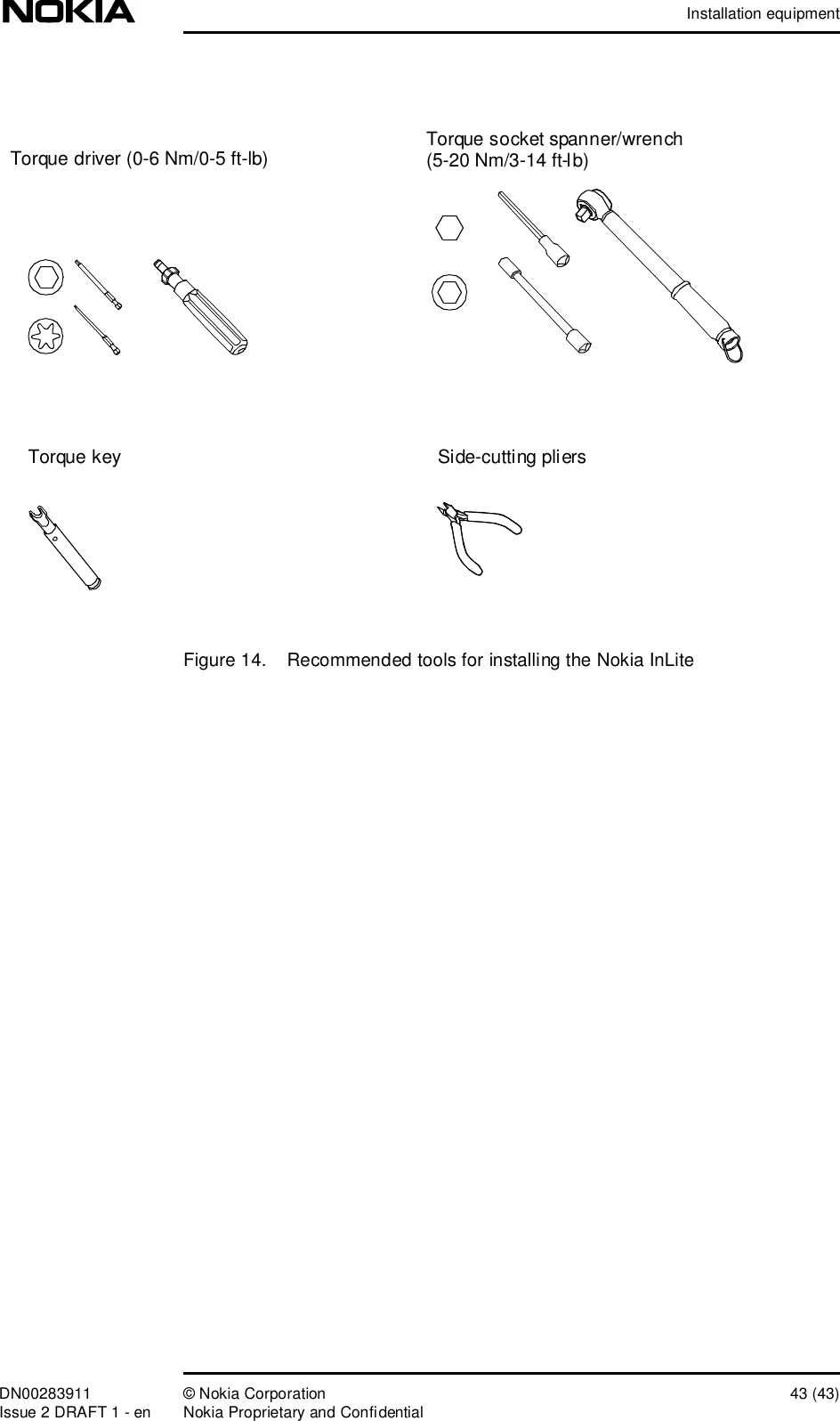
System Requirements
4.
Warnings and Cautions
5.
Revised Warnings Page
6.
Installation
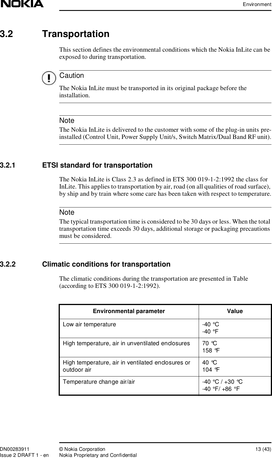
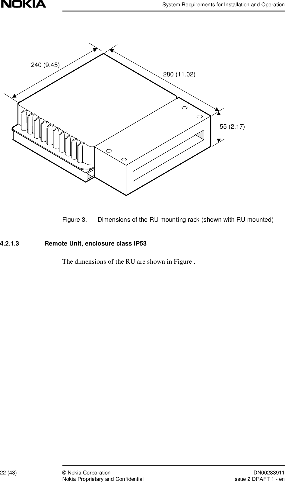
System Requirements
Navigation menu
Upload a User Manual
Namespaces
Wiki Guide
HTML
PDF
Info
Views
User Manual
Discussion / Help
Navigation