Nokia Solutions and Networks INLITERU-01 InLite Dual Band Enhancer Remote Unit User Manual System Requirements
Nokia Solutions and Networks InLite Dual Band Enhancer Remote Unit System Requirements
Contents
System Requirements

DN00283911 © Nokia Corporation 1 (43)
Issue 2 DRAFT 1 - en Nokia Proprietary and Confidential
System Requirements for Installation
and Operation
System Requirements for Installation and Operation
2 (43)© Nokia Corporation DN00283911
Nokia Proprietary and ConfidentialIssue 2 DRAFT 1 - en
The information in this document is subject to change without notice and describes
only the product defined in the introduction of this documentation. This document is
intended for the use of Nokia Networks' customers only for the purposes of the
agreement under which the document is submitted, and no part of it may be
reproduced or transmitted in any form or means without the prior written permission of
Nokia Networks. The document has been prepared to be used by professional and
properly trained personnel, and the customer assumes full responsibility when using it.
Nokia Networks welcomes customer comments as part of the process of continuous
development and improvement of the documentation.
The information or statements given in this document concerning the suitability,
capacity, or performance of the mentioned hardware or software products cannot be
considered binding but shall be defined in the agreement made between Nokia
Networks and the customer. However, Nokia Networks has made all reasonable
efforts to ensure that the instructions contained in the document are adequate and free
of material errors and omissions. Nokia Networks will, if necessary, explain issues
which may not be covered by the document.
Nokia Networks' liability for any errors in the document is limited to the documentary
correction of errors. Nokia Networks WILL NOT BE RESPONSIBLE IN ANY EVENT
FOR ERRORS IN THIS DOCUMENT OR FOR ANY DAMAGES, INCIDENTAL OR
CONSEQUENTIAL (INCLUDING MONETARY LOSSES), that might arise from the
use of this document or the information in it.
This document and the product it describes are considered protected by copyright
according to the applicable laws.
NOKIA logo is a registered trademark of Nokia Corporation.
Other product names mentioned in this document may be trademarks of their
respective companies, and they are mentioned for identification purposes only.
Copyright © Nokia Corporation 2001. All rights reserved.
Hereby, Nokia Corporation, declares that this Nokia InLite is in compliance with
the essential requirements and other relevant provisions of Directive: 1999/5/EC.
The product is marked with the CE marking and Notified Body number according
to the Directive 1999/5/EC
FCC FCC §15.21 - Information to user - The Nokia InLite is used as an intentional
radiated equipment and any changes or modifications on the equipment without
any approval by Nokia could void the user's authority to operate the equipment.
FCC §15.27 b) - Special Accessories - If a device requiring special accessories
is installed by or under the supervision of the party marketing the device, it is the
responsibility of that party to install the equipment using the special accessories.
For equipment requiring professional installation, it is not necessary for the
responsible party to market the special accessories with the equipment. However,
the need to use the special accessories must be detailed in the instruction
manual, and it is the responsibility of the installer to provide and to install the
required accessories.
0523

DN00283911 © Nokia Corporation 3 (43)
Issue 2 DRAFT 1 - en Nokia Proprietary and Confidential
FCC §15.105 - Information to user - This equipment has been tested and found
to comply with the limits for a Class B digital device, pursuant to part 15 of the
FCC Rules. These limits are designed to provide reasonable protection against
harmful interference in a residential installation. This equipment generates, uses
and can radiate radio frequency energy and, if not installed and used in
accordance with the instructions, may cause harmful interference to radio
communications. However, there is no guarantee that interference will not occur
in a particular installation. If this equipment does cause harmful interference to
radio or television reception, which can be determined by turning the equipment
off and on, the user is encouraged to try to correct the interference by one or more
of the following measures:
•Reorient or relocate the receiving antenna.
•Increase the separation between the equipment and receiver.
•Connect the equipment into an outlet on a circuit different from that to which
the receiver is connected.
•Consult the dealer or an experienced radio/TV technician for help.
System Requirements for Installation and Operation
4 (43)© Nokia Corporation DN00283911
Nokia Proprietary and ConfidentialIssue 2 DRAFT 1 - en
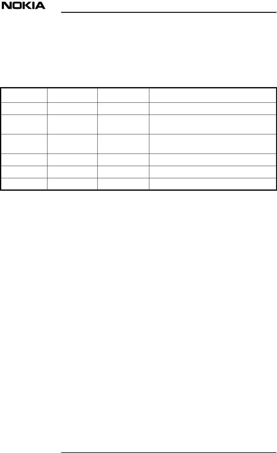
History
Date Version Author Details
26-10-2000 Draft 1T N WilliamsCompilation of a first draft
08 - 01 - 2001 Draft 2Indi Liepa Revised based on feedback from subject
matter expert.
26 - 01 - 2001 Issue 1 Indi Liepa Revised after visit to Tekmar by Harri and
review by Marc Paull.
18 - 07 - 2001 Issue 2, Draft 1Tom DumicIncluded US Type Approval information
22 - 08 - 2001 Issue 2 Tom DumicRelease for Product v1.0.1
05 - 09 - 2001 Issue 2, Draft 1Tom DumicDraft for Product v2

About this document
DN00283911 © Nokia Corporation 5 (43)
Issue 2 DRAFT 1 - en Nokia Proprietary and Confidential
1About this document
This document introduces the requirements set by Nokia for successful
installation and operation. Use this document as the source for the following
information needed in the planning of installation:
•Specification on the environmental conditions during transportation,
storage and operation
•Space requirements and other site-related installation matters
•Site grounding and power supply
•Interface connections
•Installation tools.
Read also Nokia InLite: Warnings and Cautions in conjunction with this
document.

System Requirements for Installation and Operation
6 (43)© Nokia Corporation DN00283911
Nokia Proprietary and ConfidentialIssue 2 DRAFT 1 - en

Installation site requirements
DN00283911 © Nokia Corporation 7 (43)
Issue 2 DRAFT 1 - en Nokia Proprietary and Confidential
2Installation site requirements
Prior to installation of the Nokia InLite system, it is most important that certain
actions have been carried out to ensure installation continuity and safety.
2.1 Checking the site
A number of aspects need to be verified as being satisfactory.
Accessibility
Check the following:
•Site safety access is provided
•The site is accessible to installation, commissioning and maintenance
personnel.
Grounding points
Check that the grounding point(s) are clearly identified.
Power supplies
Check that all the necessary power points are conveniently located for connection
of the Nokia InLite Main Unit (MU) and Remote Units (RUs).
Each RU requires its own power supply and a connection to the mains may be
required.
Space
Check that there is adequate space for:
•Installation work
•MU, RU and fibre optic cables.
•The recommended spacing distances for the MU and RUs as outlined in
Warnings and Cautions have been taken into account in the site planning.
Temperature and ventilation
Adequate space must be provided around the MU and RUs to ensure that the
system can be maintained within the operating temperature ranges.
Check the following:
•The site must guarantee natural ventilation to the system.

System Requirements for Installation and Operation
8 (43)© Nokia Corporation DN00283911
Nokia Proprietary and ConfidentialIssue 2 DRAFT 1 - en
•A distance of two meters must be maintained between the MU or RUs
(RUs) and a heating opening.
•The RUs should be mounted in reasonable locations.
•The RUs should not be installed inside heating or conditioning systems.
•The RUs should not be installed inside a cable pipeline.
•Bear in mind that the temperature in the upper part of a room is higher than
at eye level. If the room has a false ceiling, verify that the environment
temperatures at the installation position do not exceed the allowed limits
for the RU.
Tools
Ensure that a complete set of tools is available.
Identification of installation locations/positions
Check that the locations and positions for the installation of the MU and RUs
within the building complex have been clearly identified.
RU mounting positions
Keep into consideration that the RU transmits an RF signal and that the safety
distances must be respected.
RUs are typically installed next to the ceiling and for safety reasons they must be
properly mounted. RUs must be accessible for testing and maintenance
Cable routing
Check that the routing for the fibre optic cables between the MU and the RUs have
been clearly identified.
Documentation
The required documents should be available:
•Site-specific installation documents, providing information on cabling
routes, RU and MU locations, power supplies and so forth
•Nokia InLite User Manual
•BTS User Manuals (if required).
BTS status
In order to test the Nokia InLite, the BTSs should have been commissioned and
the Abis links established.
If the Abis link has not been set up, a power meter is required to to measure signal
levels.
Power connections
The MU grounding and AC power sockets and the RU AC power supply sockets
should be installed either before installation begins or early in the installation
process.

Installation site requirements
DN00283911 © Nokia Corporation 9 (43)
Issue 2 DRAFT 1 - en Nokia Proprietary and Confidential
2.2 Checking the site environment
Check that the following requirements are satisfactory at the site:
•The site storage, transportation and operation of the Nokia InLite must
conform with the various international and national environmental
standards for temperature, humidity, EMC and noise.
•There is no explosion risk present
•The environment is not classified as a high-risk area in the event of fire
•Suspended particles are not to be found in great concentration
•The environment is not subject to any traffic which could cause crash
damages
• It is recommended that the MU is placed in a private room, protected
against any possible violation
•The system is not exposed to ultra-violet rays.

System Requirements for Installation and Operation
10 (43)© Nokia Corporation DN00283911
Nokia Proprietary and ConfidentialIssue 2 DRAFT 1 - en
Environment
DN00283911 © Nokia Corporation 11 (43)
Issue 2 DRAFT 1 - en Nokia Proprietary and Confidential
Caution
3Environment
This chapter defines the classes of environmental conditions and their severities
to which the Nokia InLite can be exposed. The information is organised in the
following parts:
•Conditions for Storage
•Conditions for Transportation
•Conditions for Operation
3.1 Storage
This section defines the environmental conditions, to which the Nokia InLite can
be exposed during storage.
The Nokia InLite must be stored in its original package before the installation.
3.1.1 ETSI standard for storage
The Nokia InLite system complies with ETS 300 019-1-1:1992 Class 1.2 weather
protected, partly temperature-controlled storage locations.
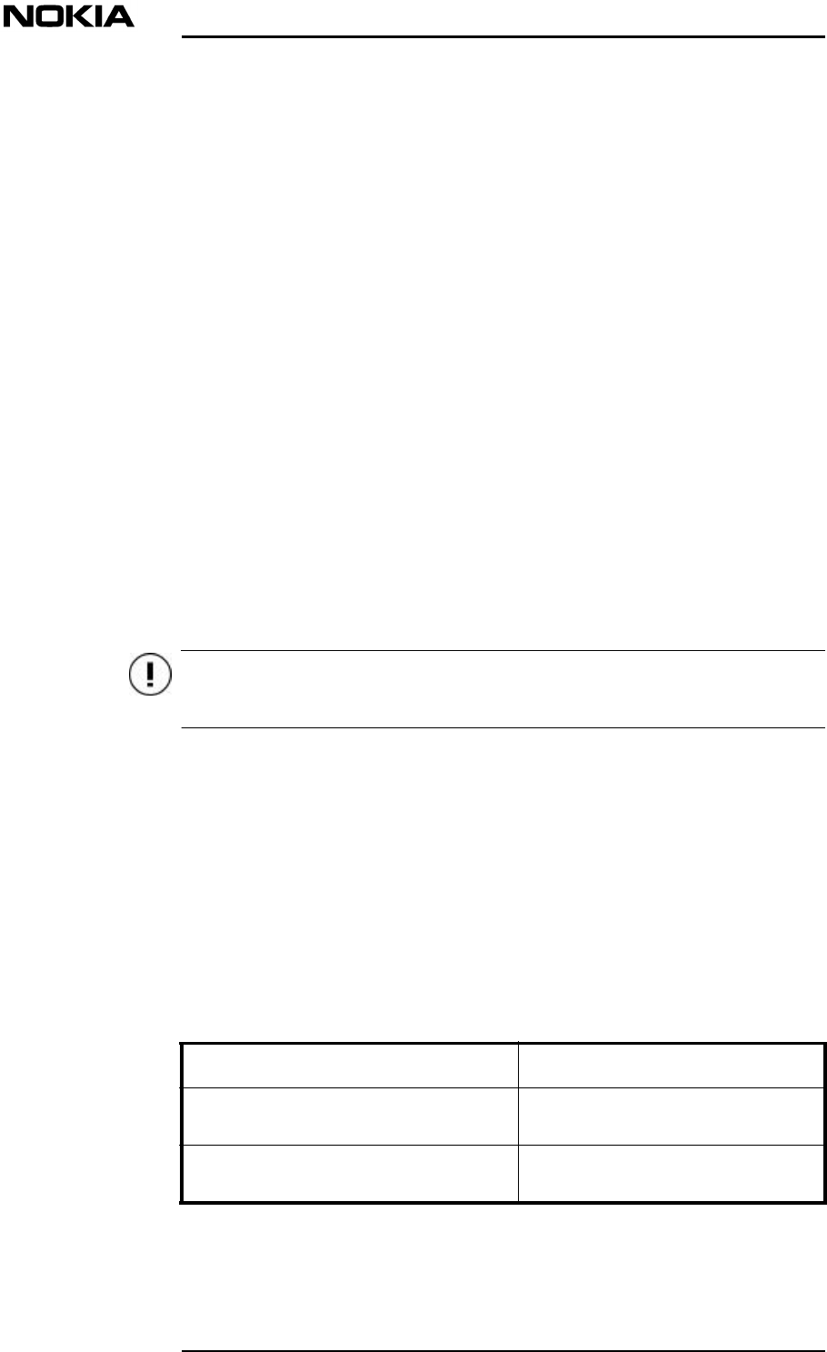
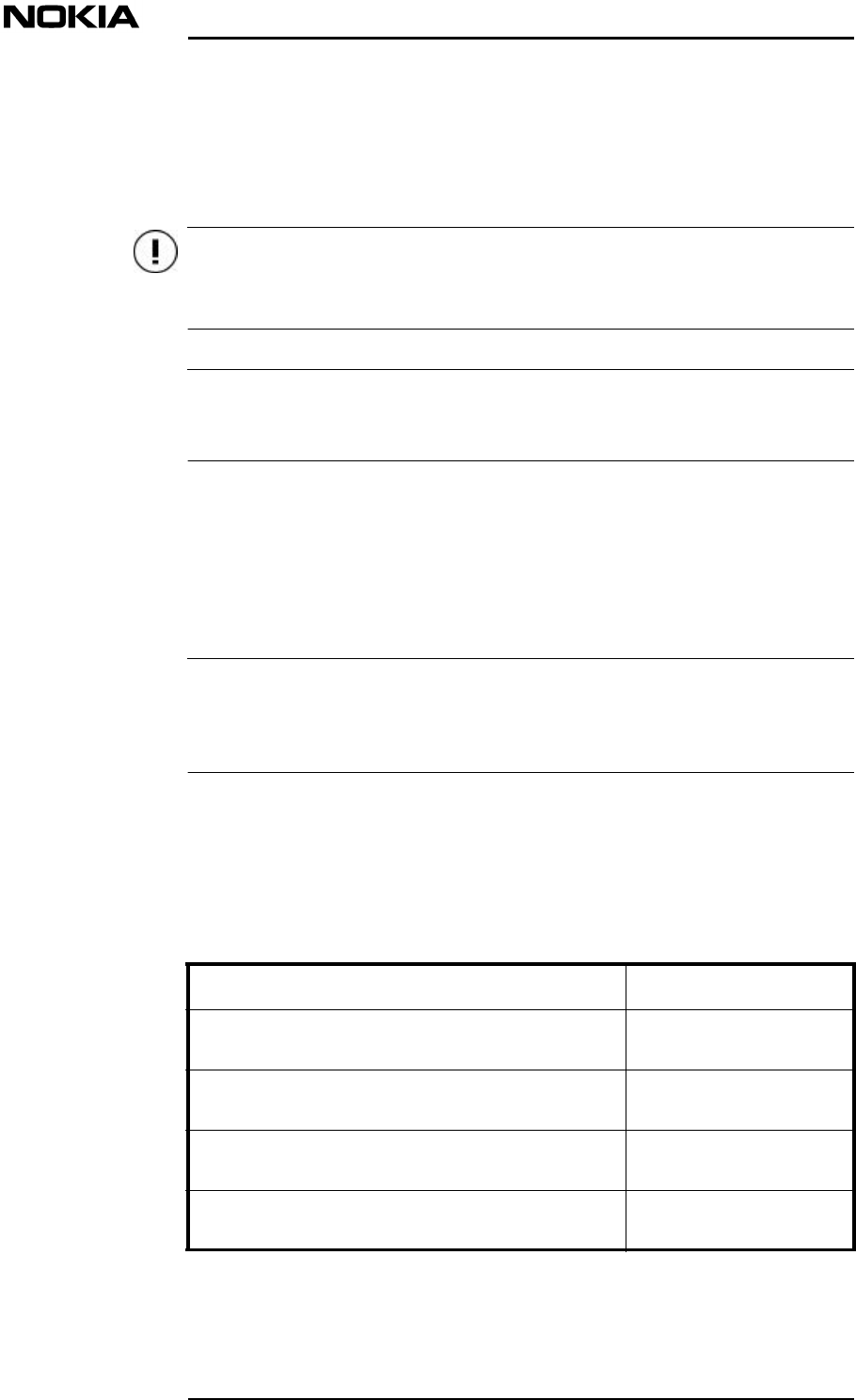
3.1.2 Climatic conditions for storage
The climatic conditions for the storage of the Nokia InLite system (as specified
ETS 300 019-1-1:1992) are described in Table .
Environmental parameter Value
Low air temperature- 25 °C
- 13 °F
High air temperature55 °C
131 °F
System Requirements for Installation and Operation
12 (43)© Nokia Corporation DN00283911
Nokia Proprietary and ConfidentialIssue 2 DRAFT 1 - en
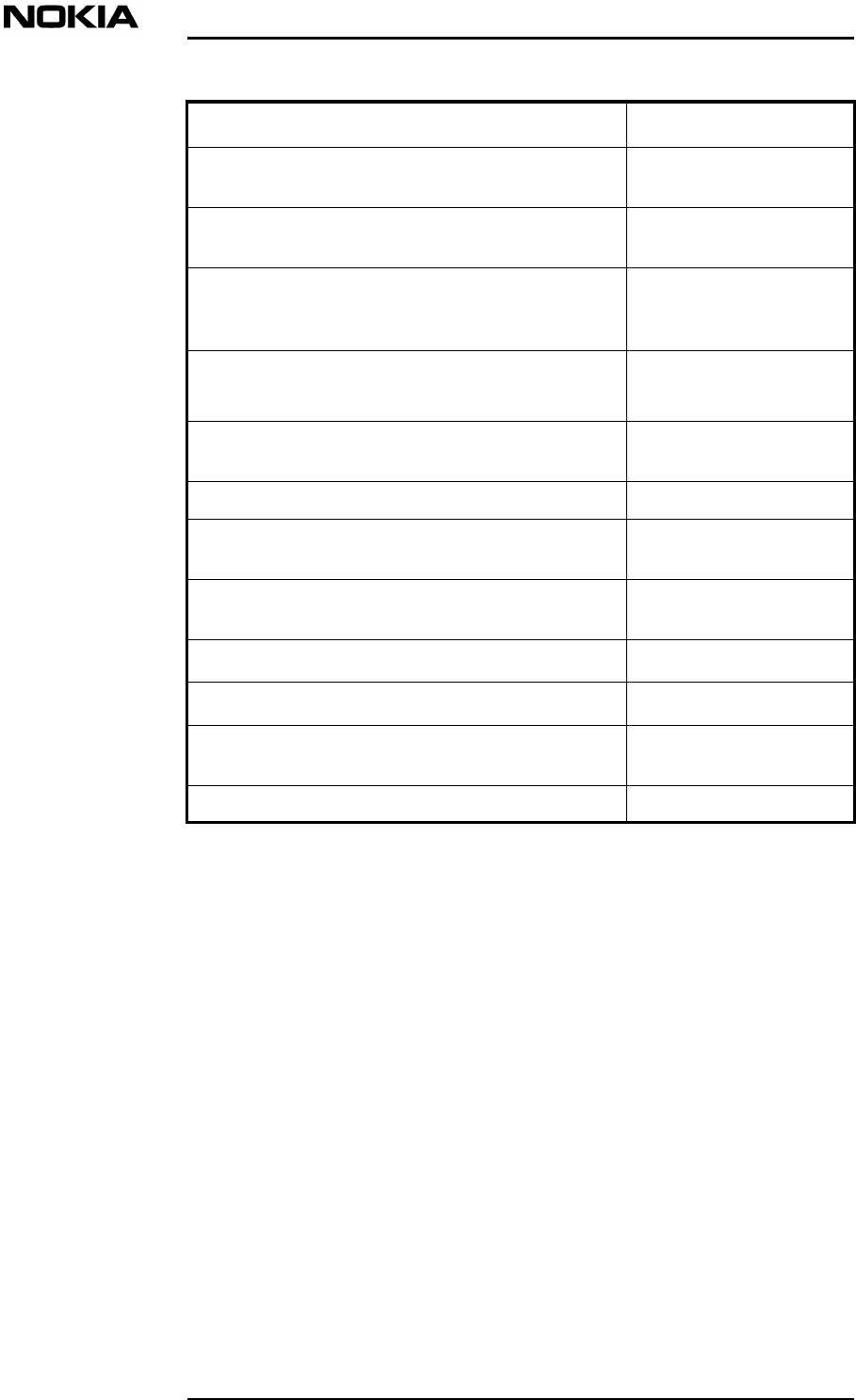
Table 1. Climatic conditions for storage
3.1.3 Mechanical conditions for storage
The Nokia InLite System complies with ETS 300 019-1-1:1992 class 1.2.
Low relative humidity10%
High relative humidity100%
Low absolute humidity0.5 g/m3
High absolute humidity29 g/m3
Rain intensitynone
Temperature change rate (average of 5
minutes)0.5 °C/min.
0.9 °F/min.
Low air pressure70 kPa
10.15 psi
High air pressure106 kPa
15.37 psi
Solar radiation 1120 W/m2
Surrounding air movement30 m/s
98 ft/s
Conditions of condensation yes
Conditions of precipitation (rain, snow,
hail, etc.) yes
Low rain temperaturenone
Conditions of water from sources other
than rain dripping water
Conditions of icing and frostingyes
Environmental parameter Value
Environment
DN00283911 © Nokia Corporation 13 (43)
Issue 2 DRAFT 1 - en Nokia Proprietary and Confidential
Caution
Note
Note
3.2 Transportation
This section defines the environmental conditions which the Nokia InLite can be
exposed to during transportation.
The Nokia InLite must be transported in its original package before the
installation.
The Nokia InLite is delivered to the customer with some of the plug-in units pre-
installed (Control Unit, Power Supply Unit/s, Switch Matrix/Dual Band RF unit).
3.2.1 ETSI standard for transportation
The Nokia InLite is Class 2.3 as defined in ETS 300 019-1-2:1992 the class for
InLite. This applies to transportation by air, road (on all qualities of road surface),
by ship and by train where some care has been taken with respect to temperature.
The typical transportation time is considered to be 30 days or less. When the total
transportation time exceeds 30 days, additional storage or packaging precautions
must be considered.
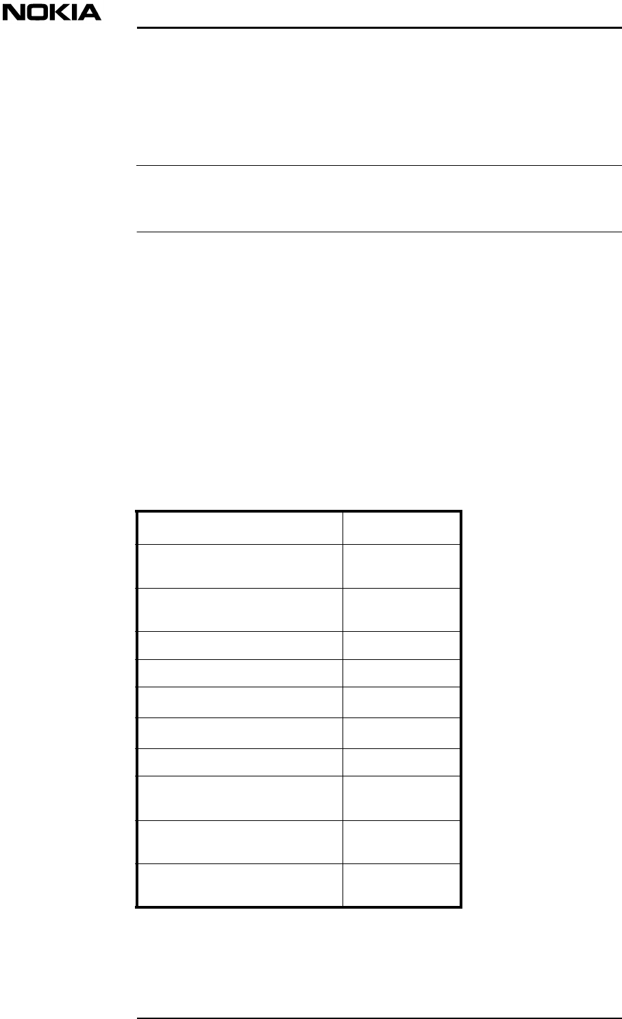
3.2.2 Climatic conditions for transportation
The climatic conditions during the transportation are presented in Table
(according to ETS 300 019-1-2:1992).
Environmental parameter Value
Low air temperature-40 °C
-40 °F
High temperature, air in unventilated enclosures 70 °C
158 °F
High temperature, air in ventilated enclosures or
outdoor air 40 °C
104 °F
Temperature change air/air -40 °C / +30 °C
-40 °F/ +86 °F
System Requirements for Installation and Operation
14 (43)© Nokia Corporation DN00283911
Nokia Proprietary and ConfidentialIssue 2 DRAFT 1 - en
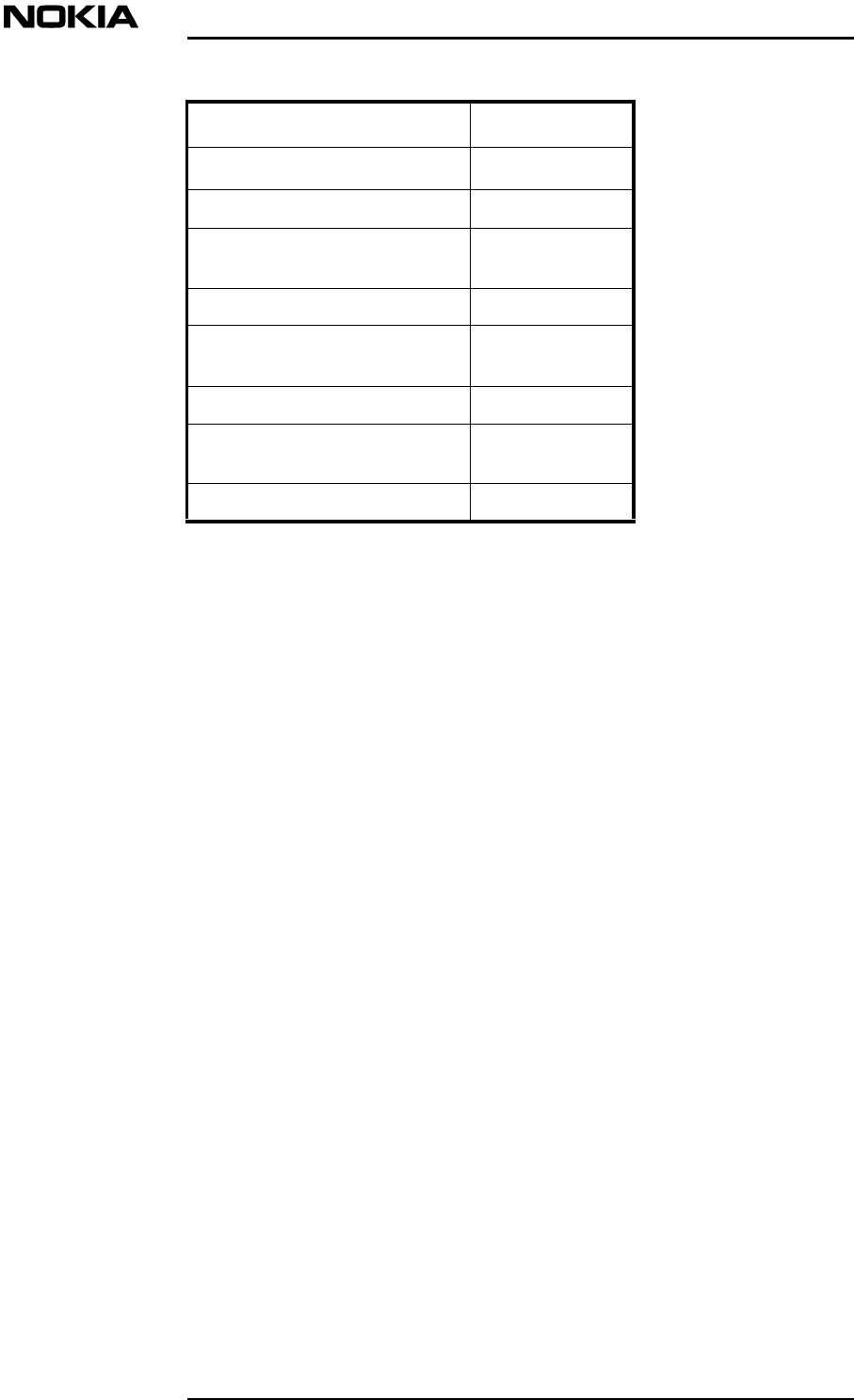
Table 2. Climatic conditions for transportation
3.2.3 Mechanical conditions for transportation
For mechanical conditions during transportation, the Nokia InLite complies with
ETS 300 019 1-2:1992 class 2.3.
Temperature change air/water+40/+5 °C
+104/+41 °F
Relative humidity, not combined with rapid
temperature changes 95% +40 °C
95% 104 °F
Relative humidity, combined with rapid
temperature changes air/air, at high relative
humidity
95% -40 °C /+30 °C
95% -40 °F/ +86 °F
Absolute humidity, combined with rapid
temperature changes air/air, at high water content60 g/m3 +70/+15 °C
60 g/m3 +158/+59 °F
Low air pressure70 kPa
10.15 psi
Change of air pressurenone
Surrounding air movement20 m/s
65.6 ft/s
Precipitation, rain 6 mm/min.
0.24 in/min.
Radiation, solar1120 W/m2
Radiation, heat600 W/m2
Water from sources other than rain 1 m/s
3.28 ft/s
Wetness none
Environmental parameter Value
Environment
DN00283911 © Nokia Corporation 15 (43)
Issue 2 DRAFT 1 - en Nokia Proprietary and Confidential
Note
3.3 Operation
This section defines the environmental conditions during the operation of the
Nokia InLite at locations which are not protected from direct weather influences.
When surveying the prospective sites, consider the values presented in this
section.
Operating conditions are defined as stationary: the equipment is mounted on a
structure, or on a mounting device, or it is permanently placed at a certain site.
The Nokia InLite is not intended for portable use.
3.3.1 ETSI standard for operation
The InLite is Class 3.1 as defined in ETS 300 019-1-4:1992
3.3.2 Climatic conditions for operation
For climatic conditions during operation, the Nokia InLite complies generally
with class 3.1 as presented in Table .
Environmental parameter Value
Low air temperature+5 °C
+41°F
High air temperature40 °C
104°F
Low relative humidity5%
High relative humidity85%
Low absolute humidity1 g/m3
High absolute humidity25 g/m3
Rain intensityNot applicable
Temperature change rate
(average of 5 minutes)0.5 °C/min.
0.9 °F/min.
Low air pressure70 kPa
10.15 psi
High air pressure106 kPa
15.37 psi
System Requirements for Installation and Operation
16 (43)© Nokia Corporation DN00283911
Nokia Proprietary and ConfidentialIssue 2 DRAFT 1 - en
Table 3. Climatic conditions for operation, Class 3.1
3.3.3 Mechanical conditions for operation
For mechanical conditions during operation, the Nokia InLite complies with ETS
300 019-1-4:1992 class 3.1.
3.3.4 EMC shielding
The chassis and the units of the Nokia InLite together provide the EMC shielding.
The EMC shielding complies to the requirements set by the following standards:
•GSM 11.21
•ETS 300, 342-3
•Title 47 CFR FCC part 15
For more specific information refer to Nokia InLite: Product Description.
3.3.5 Safety
The Nokia InLite conforms to:
•EN 60950 (including amendments 1,2,3 and 4) Safety of Information
Technology equipment including electrical business equipment.
•IEC 950 2nd Ed 1991. Safety of Information Technology equipment
(including amendments 1,2,3 and 4 and including all Competent Body
Solar radiation 700 W/m2
Heat radiation insignificant
Surrounding air movement5m/s
164 ft./s
Conditions of condensation Yes
Conditions of precipitation
(rain, snow, hail etc.) No
Low rain temperatureNot applicable.
Conditions of water from
sources other than rain Not applicable.
Conditions of icing and frostingNo
Environmental parameter Value

Environment
DN00283911 © Nokia Corporation 17 (43)
Issue 2 DRAFT 1 - en Nokia Proprietary and Confidential
Scheme Group and National Deviations as detailed in CB Bulletin 96A
March 2000.
•UL 3rd Ed.
•CSA C22.2 Number 950 Revision June 1998

System Requirements for Installation and Operation
18 (43)© Nokia Corporation DN00283911
Nokia Proprietary and ConfidentialIssue 2 DRAFT 1 - en

Installation requirements
DN00283911 © Nokia Corporation 19 (43)
Issue 2 DRAFT 1 - en Nokia Proprietary and Confidential
4Installation requirements
This chapter specifies the preparatory requirements for the installation of the
Nokia InLite system.
4.1 Checking the site
Before the Nokia InLite can be installed, the site must be properly surveyed and
prepared, and all the required external services must be correctly installed. The
site survey must identify any special requirements for the installation.
The site must meet the following requirements before the installation can begin:
1. The site is accessible and safe for working.
2. The safety distance calculations as presented in Nokia InLite: Warnings
and Cautions have been made and taken into account.
3. External connections for the MU (grounding point and mains power
supply) are available.
4. External connections for the RUs (mains power).
5. All required documentation is available, for example, site-specific
installation instructions and User Manual.
6. The correct delivery has been brought to the site.
4.2 Space requirements
The MU can be mounted on a wall, pole or other vertical support.
The RUs and the mounting rack can be mounted on a wall or pole or other vertical
support.
This section presents general issues that must be considered when choosing the
installation space.
4.2.1 Dimensions and weight
4.2.1.1 Main Unit
Figure shows the dimensions of the MU.
System Requirements for Installation and Operation
20 (43)© Nokia Corporation DN00283911
Nokia Proprietary and ConfidentialIssue 2 DRAFT 1 - en
Figure 1. Dimensions of Nokia InLite Main Unit
The MU weighs approximately 16.5 kg (36 lb.). The mounting frame weighs
approximately 2 kg (4.4 lb.).
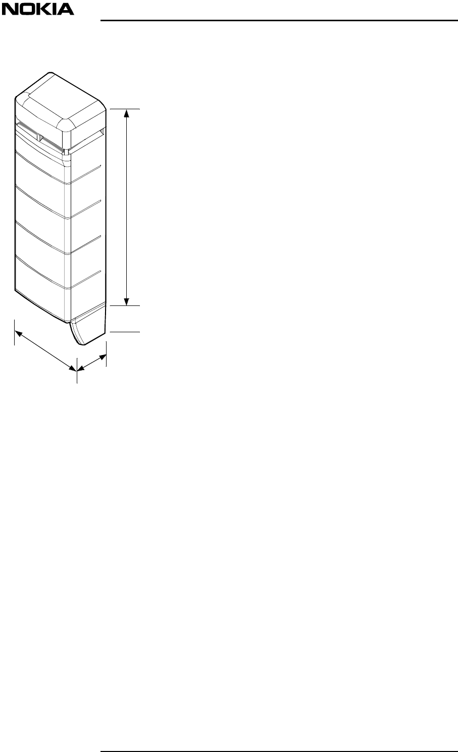
4.2.1.2 Remote Unit and mounting rack, enclosure class IP41
The dimensions of the RU are shown in Figure .
840mm
(33.1)
114mm
(4.5)
215mm
(8.5)
310mm
(12.2)
NOTE: Dimensions in mm (inch)
Installation requirements
DN00283911 © Nokia Corporation 21 (43)
Issue 2 DRAFT 1 - en Nokia Proprietary and Confidential
Figure 2. Dimensions of the Remote Unit
The RU weighs 1.7 kg (3.8lb).
The dimensions of the mounting rack are shown in Figure
240 (9.45)
222 (8.74)
37 (1.46)
NOTE: Dimensions in mm (inch)
System Requirements for Installation and Operation
22 (43)© Nokia Corporation DN00283911
Nokia Proprietary and ConfidentialIssue 2 DRAFT 1 - en
Figure 3. Dimensions of the RU mounting rack (shown with RU mounted)
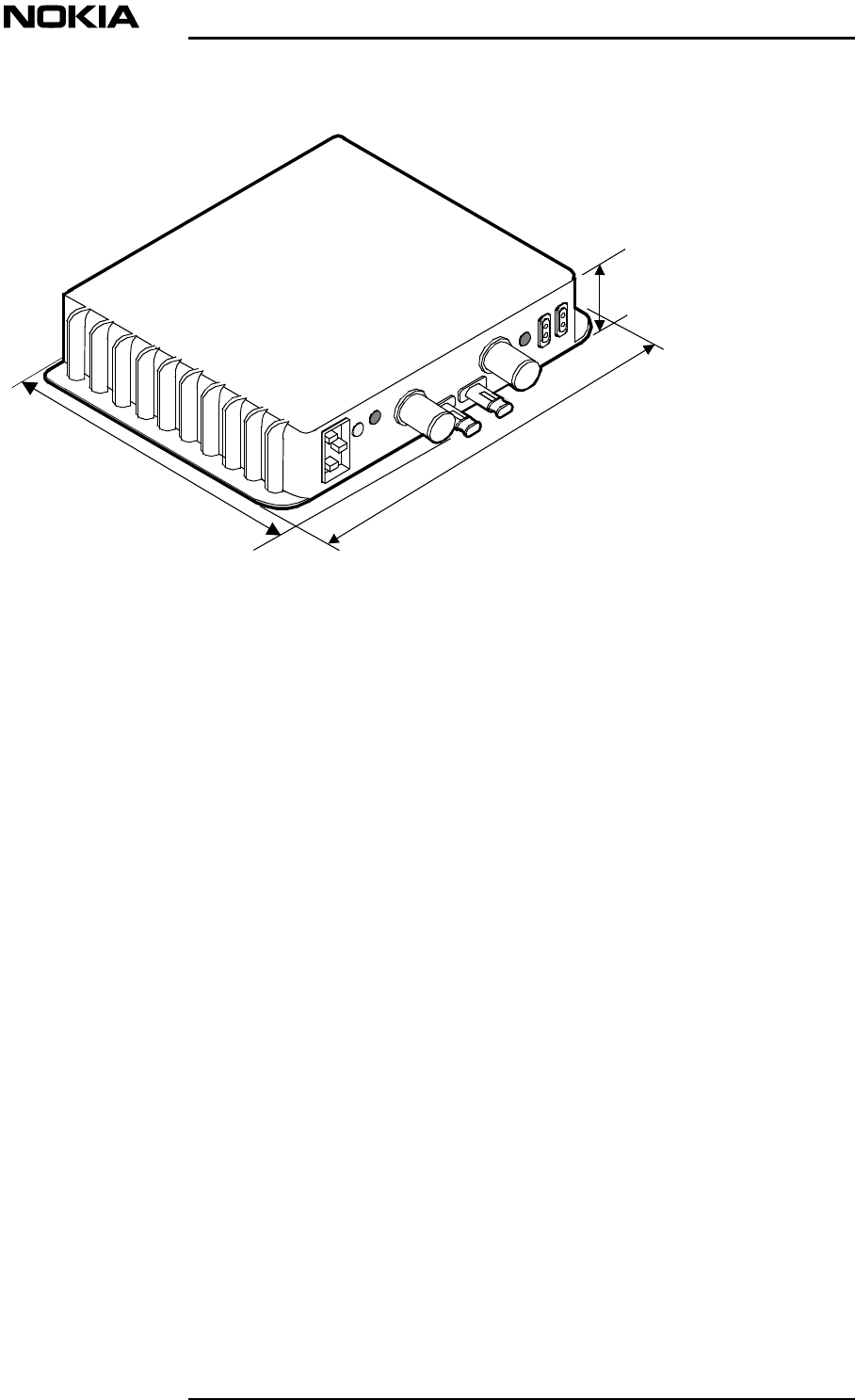
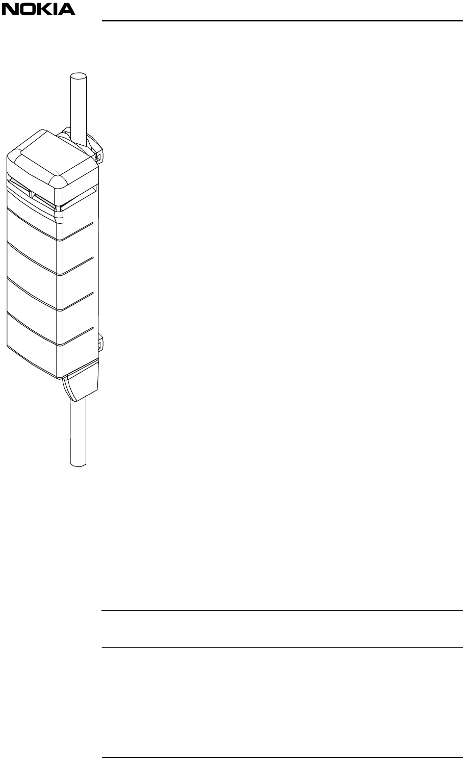
4.2.1.3 Remote Unit, enclosure class IP53
The dimensions of the RU are shown in Figure .
240 (9.45)
280 (11.02)
55 (2.17)

Installation requirements
DN00283911 © Nokia Corporation 23 (43)
Issue 2 DRAFT 1 - en Nokia Proprietary and Confidential
Figure 4. Dimensions of the Remote Unit
The RU weighs 2.5 kg (5.5lb).
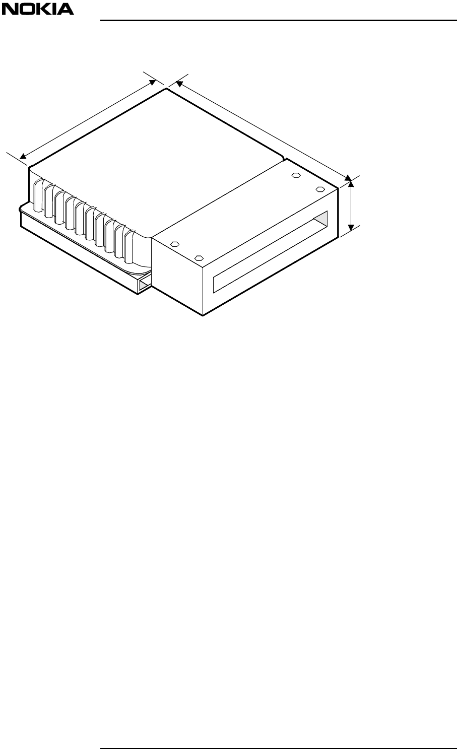
4.2.1.4 Remote Unit, enclosure class IP64
The dimensions of the RU are shown in Figure .

System Requirements for Installation and Operation
24 (43)© Nokia Corporation DN00283911
Nokia Proprietary and ConfidentialIssue 2 DRAFT 1 - en
Figure 5. Dimensions of the Remote Unit
The RU weighs 11 kg (24.25lb).
4.2.2 Clearances around the Main Unit and Remote Units
4.2.2.1 Main Unit
The required clearances around the MU are shown in Figure .
Installation requirements
DN00283911 © Nokia Corporation 25 (43)
Issue 2 DRAFT 1 - en Nokia Proprietary and Confidential
Figure 6. Clearances around the Main Unit
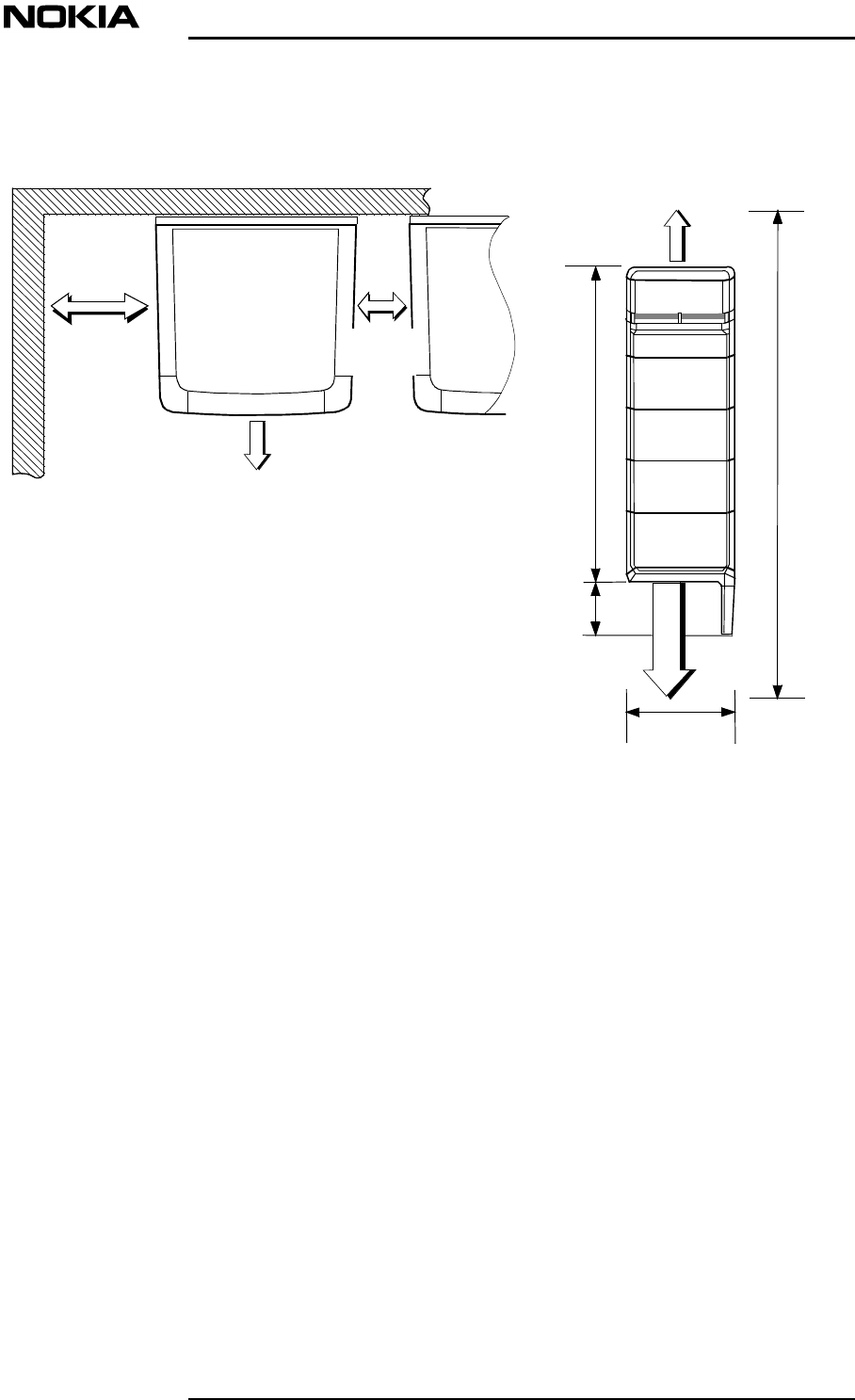
4.2.2.2 Remote Unit and mounting rack
The required clearances around the RU IP41 and the mounting rack are shown in
Figure
Front view
200 (7.88)
400
(15.74)
840 (33.1)
310 (12.2)
100 (3.94)
Top view
1454 (57.28)
100
(3.94)
114 (4.5)
400 (15.74)
System Requirements for Installation and Operation
26 (43)© Nokia Corporation DN00283911
Nokia Proprietary and ConfidentialIssue 2 DRAFT 1 - en
Figure 7. Clearances around the Remote Unit IP41
The clearances are required for:
•Lifting the unit from the rack
•Fibre optic cables, antenna cables and power cables.
The required clearances arond the IP53 RU are shown in Figure XX.
Note: Dimensions in mm (inch)
50 (1.97)50 (1.97)
100 (3.94)
400 (15.7)

Installation requirements
DN00283911 © Nokia Corporation 27 (43)
Issue 2 DRAFT 1 - en Nokia Proprietary and Confidential
Figure 8. Clearances around the Remote Unit IP53
The required clearances arond the IP64 RU are shown in Figure XX.

System Requirements for Installation and Operation
28 (43)© Nokia Corporation DN00283911
Nokia Proprietary and ConfidentialIssue 2 DRAFT 1 - en
Figure 9. Clearances around the Remote Unit IP64
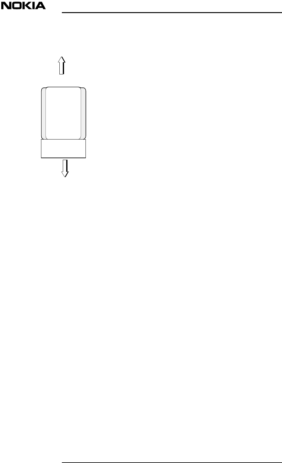
4.3 Mounting locations and positions
4.3.1 Main Unit
The MU can only be installed at indoor locations and should be mounted
vertically on a wall, pole or other vertical support.
Installation requirements
DN00283911 © Nokia Corporation 29 (43)
Issue 2 DRAFT 1 - en Nokia Proprietary and Confidential
Note
Figure 10. Mounting position of Nokia InLite Main Unit
4.3.2 RU and mounting rack
The RU can be mounted on a wall, pole or other vertical support.
The RU and mounting rack are mounted vertically.
The RU and mounting rack should never be installed on a ceiling.
A local AC power socket must be provided at the installation location or
alternatively, a centralised DC power supply may be used.

System Requirements for Installation and Operation
30 (43)© Nokia Corporation DN00283911
Nokia Proprietary and ConfidentialIssue 2 DRAFT 1 - en
Note
4.4 Requirements for wall and pole installation
Qualified personnel must inspect the installation wall and/or pole or other vertical
support before mounting the MU, RU and mounting rack. The installation wall or
pole must be strong enough to bear the weight of each unit.
The optional pole mounting kit can be used when the installation pole diameter is
between 60 and 300 mm (2.36 and 11.81 in). These dimensions are applicable to
the MU. The RU can be mounted on a thinner pole.
Anchor screws
The anchor “Fishers” screws are used for attaching the MU and mounting frame
and RU with the mounting rack to the wall.
The MU anchor screws must be M6 size, stainless steel with the minimum
breaking strength (Rm) of 800 N/mm2. An appropriate counterpart for the anchor
screw (for example, an anchor plug) must be selected according to the screw and
the mounting base material. If the anchor screws are of other standard than the
metric standard, they must be selected so that they meet the requirement set to the
metric standard screws mentioned above.
4.5 Grounding
To protect the MU from damaging overvoltages through communication cables,
or power supply lines, grounding cabling must be planned and installed before the
installation of the MU. To avoid interference, it is recommended that large
grounding systems be designed case-specifically.
A power plug with protective ground connection is not sufficient for the MU.
Grounding must have a fixed, non-removable connection.
Regulations issued by local authorities/legislation must be followed when
planning the grounding of a site!
In general, grounding is planned as follows:
•The grounding cable is connected with screws or with a nut to the
grounding point of the MU. The grounding cable must be fitted with an
appropriate lug.
•The minimum cross-section of the copper grounding conductor is 2.5 mm2
•The maximum cross-section of the copper grounding conductor is 35 mm2
•The maximum value of ground resistance is 10 mΩ
•The ground cable must be connected to a main grounding busbar
Installation requirements
DN00283911 © Nokia Corporation 31 (43)
Issue 2 DRAFT 1 - en Nokia Proprietary and Confidential
Note
WARNING
•The routing of the ground cable must be as direct as possible. Unnecessary
loops should be avoided.
A grounding cable can be ordered from Nokia.
4.6 Mains power
Follow the national legislation when working with the power supply. It is
advisable that the socket used for the MU and RUs are permanently wired in
accordance with current local and national wiring standards.
All ground connections must be secure and non-removable.
All power cabling must meet the requirements of the appropriate national
standard.
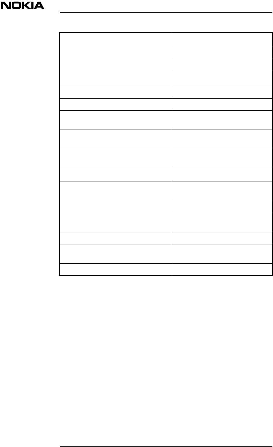
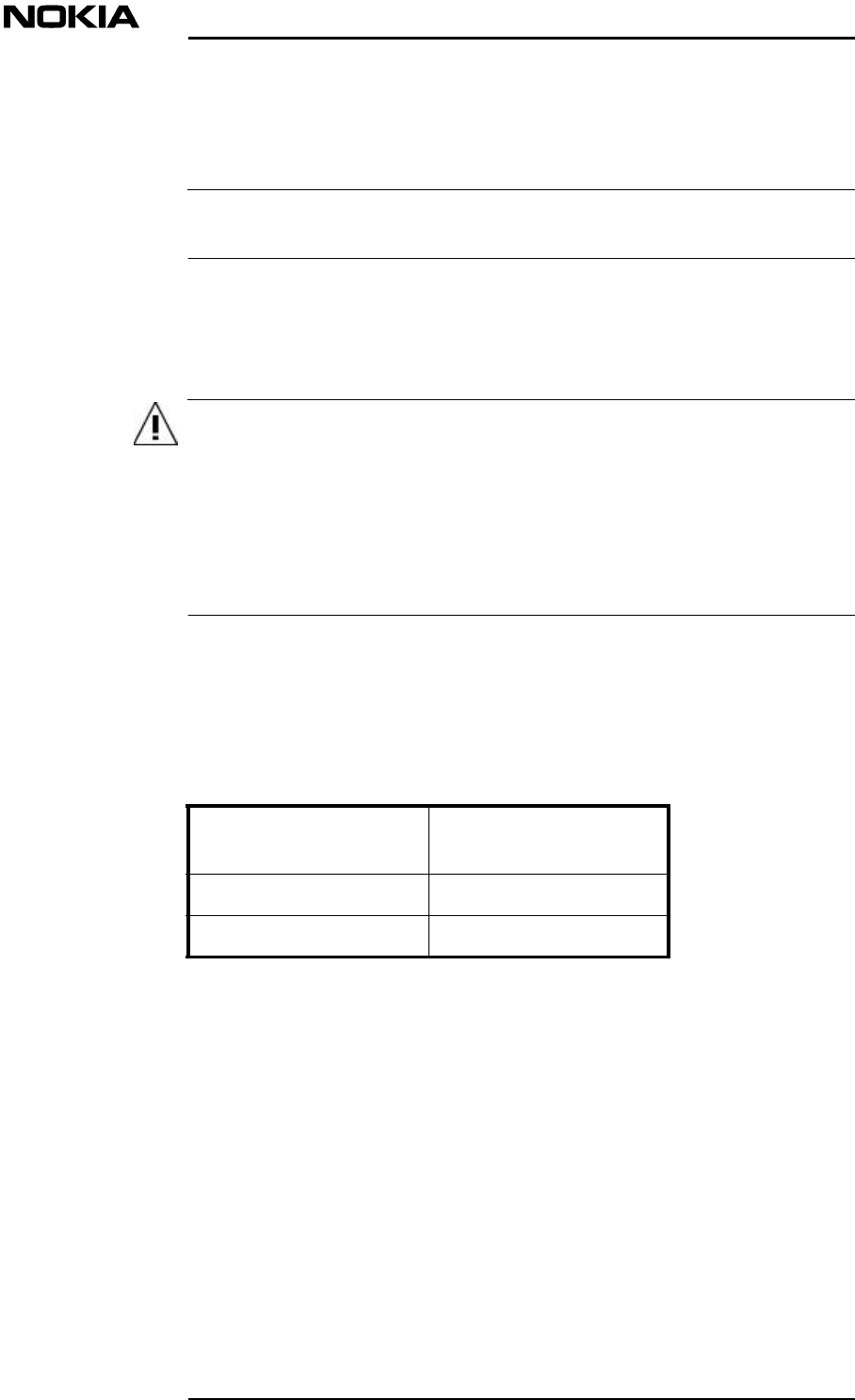
4.6.1 Main Unit
The MU has two power supply options: 220 VAC and 110 VAC. The permitted
voltage fluctuation for the different options is presented in Table .
Table 4. Permitted operating voltage fluctuation
It is recommended that the AC mains be protected with a transient overvoltage
protector circuit breaker. This protection is not included in the MU.
4.6.2 Remote Unit
The RU has the following power supply options:
•110 VAC
Nominal operating
voltage Permitted operating
voltage fluctuation
220 VAC ±20%
110 VAC ±20%
System Requirements for Installation and Operation
32 (43)© Nokia Corporation DN00283911
Nokia Proprietary and ConfidentialIssue 2 DRAFT 1 - en
Note
Note
•220 VAC
•-48 VDC
4.6.3 Power consumption
The power consumption of the MU is dependent on the RU configuration.The
consumption of the MU is less than 100 W.
The power consumption of one RU is 15 W.
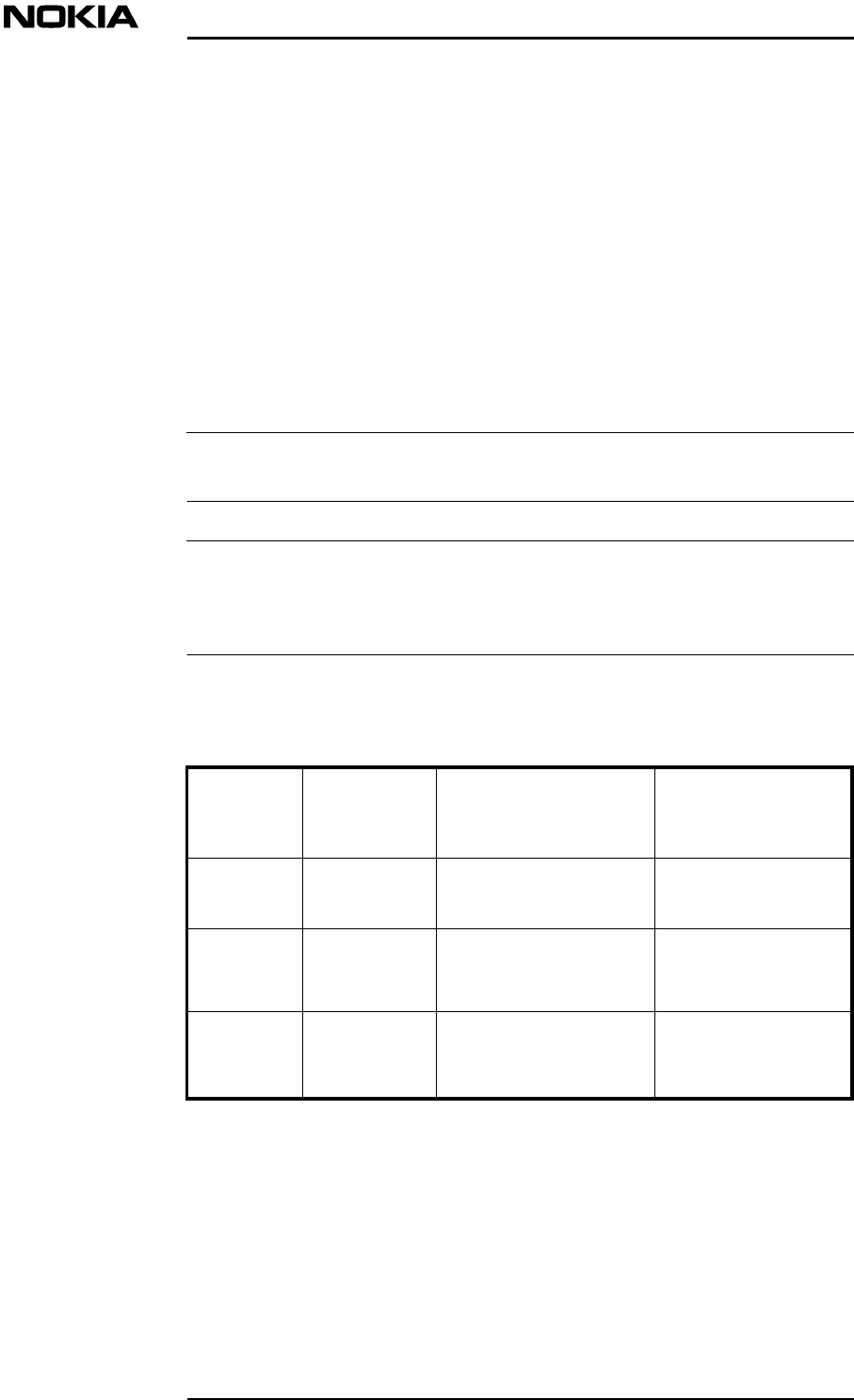
4.6.4 Connectors, cables and fuses for cable protection
A prefabricated mains power cable for the RU is supplied by Nokia.
If you use the prefabricated mains power cable supplied by Nokia, make sure that
the power distribution box (mains power supply) is located no further than 10
metres from the Nokia InLite MU.
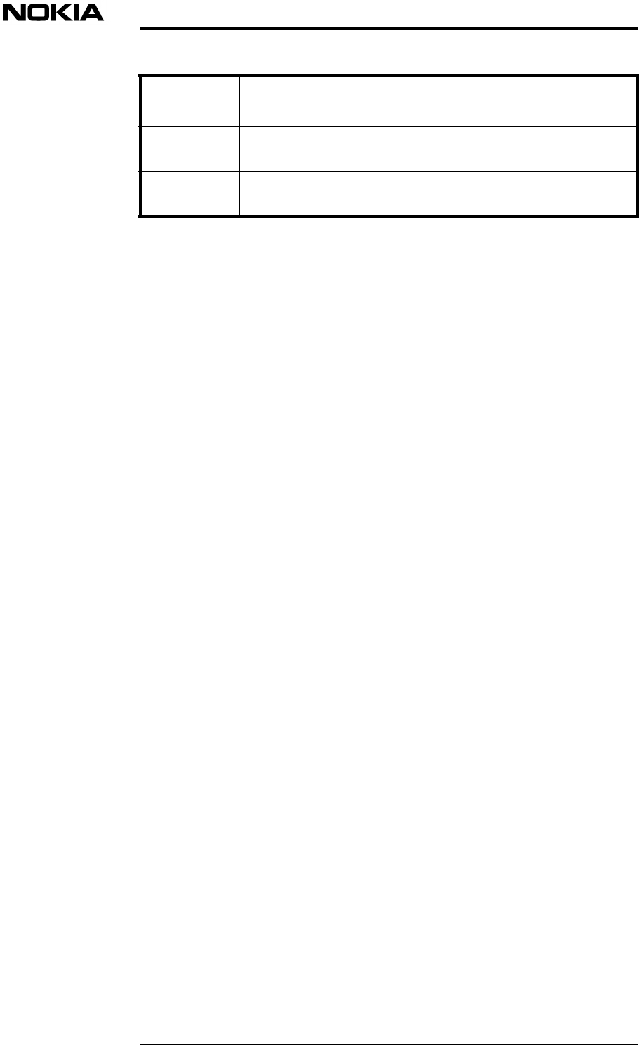
Table presents the requirements for the RU power supply cables, connectors and
the recommended mains fuses.
Power
supply
type
Connector
type at the
end of cable Cable Recommended
fuse for cable
protection
AC supply
220VIEC 320
(female)Multicore cable 3 x
0.75 to 1.5 mm2 10A for 1.5 mm2
6A for 0.75 mm2
AC supply
110VIEC 320
(female) with
notch
Multicore cable 3 x 1.5
mm2
10 A
DC supply
-48V
(optional)
Bayonet
(female)Composite fibre optic/
copper cable, twinfibre,
2x15mm 2
-
Installation requirements
DN00283911 © Nokia Corporation 33 (43)
Issue 2 DRAFT 1 - en Nokia Proprietary and Confidential
Note
Caution
Table 5. Connectors, cables and recommended fuses
In general, the fuses for cable protection have to be rated according to the national
electrical safety regulations.
4.7 Painting the Main Unit cover
If desired, the MU cover can be painted to make it better blend into the
surrounding environment. Some dark colours with higher absorptivity may be
restricted.
Nokia recommends that for painting the cover, a primer-topcoat combination of
Beckers TD 130 primer (for priming) and Beckers TH 141 paint (for surface
painting) be used. Other paints suitable for polycarbonate surfaces may also be
used.
Do not use any paint that contains alkalis, esters, ketones, aromatic, chlorinated,
or fluorinated hydrocarbons, since these may damage the cover. Paint containing
these chemicals can only be used if approved by the manufacturer for painting
polycarbonate objects.
The selected paint must be UV and weather-resistant, and suitable for
temperatures ranging from -40 °C to +50 °C (-40 °F to 122 °F). For environmental
conditions, refer to ETS 300 019-1-4:1992 class 4.1.
To paint the Nokia InLite cover:
1. Remove the MU cover as instructed.
2. Before painting, detach the cable cover and the cable cover support from
each other to prevent them from sticking to each other by paint and to
ensure that paint is applied evenly. The cover top can also be detached from
the cover by unscrewing the Torx T20 screws (see Figure ).

System Requirements for Installation and Operation
34 (43)© Nokia Corporation DN00283911
Nokia Proprietary and ConfidentialIssue 2 DRAFT 1 - en
Figure 11. Removing the cover top
3. Remove stains and dust from the surface of the cover with an alcoholic or
acidic wash, or wipe it clean with a piece of cloth moistened with water and
mild washing agent. Do not use washing agents that contain alkalis,
aromatic, chlorinated, or fluorinated hydrocarbons, esters or ketones.
4. Rinse with water to remove any residue of cleaning chemicals.
5. Dry the cover parts by blowing ionized air on them to remove electrostatic
charges and dust particles.
6. Place a support under the cover and the cover top so that you do not have
to touch the parts during painting.
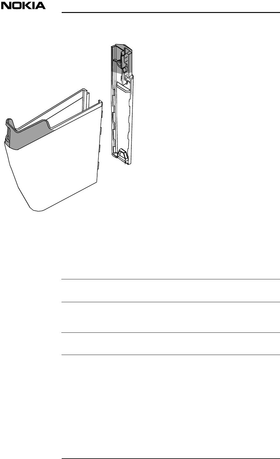
7. Use a clamp or hook for holding the cable cover and the cable cover
support during painting. See Figure for areas on which to place the clamp.
Installation requirements
DN00283911 © Nokia Corporation 35 (43)
Issue 2 DRAFT 1 - en Nokia Proprietary and Confidential
Note
Note
Figure 12. Areas used for holding the cable cover parts during painting
8. Spray paint over the outside surface of the cover. Spraying should be done
at room temperature with relative air humidity of 50-65%.
The maximum thickness of the paint should not exceed 100 µm.
9. Dry the parts either in an oven or let the paint dry at room temperature
according to the paint manufacturer’s drying instructions.
The temperature of the drying oven must not exceed 90 °C (194 °F).
10. After the paint is dry, attach the cover top to the cover. Tighten the screws
to 1.6 Nm (1.18 ft-lb.).

System Requirements for Installation and Operation
36 (43)© Nokia Corporation DN00283911
Nokia Proprietary and ConfidentialIssue 2 DRAFT 1 - en
Interfaces and cables
DN00283911 © Nokia Corporation 37 (43)
Issue 2 DRAFT 1 - en Nokia Proprietary and Confidential
Note
5Interfaces and cables
This chapter describes the external interfaces and interconnecting cables
(excluding the grounding and power supply cables) for the Nokia InLite.
The following cables can be ordered from Nokia.
•RF jumper cables between MU and BTS
•fibre optic cables between the MU and RUs
•Pigtails to be spliced to core fibre optic cables
•LMP cable between MU LMP connector and laptop PC
•Alarm cable between MU alarm port and BTS
Refer to Appendix A for ordering information.
5.1 Main Unit
The interface connectors of the MU are shown in Table . Interfaces and
connectors of the Local Units (LUs) of the MU are shown in a separate table.
Interface
connector Number of
connectors Connector
type Cable type/diameter
TRX BTS 8N-type,
(female)RG223
Alarm port1 (5-pin) 9-pin, D-type,
female13-pair 28 AWG, 106 Ω
Flexible SCSI-2 Cable
type CL2/FT1
Local
Management
Port
1 (3-pin) 9-pin, D-type,
male2-pair telecom cable. For
more information, refer to
Appendix A.
System Requirements for Installation and Operation
38 (43)© Nokia Corporation DN00283911
Nokia Proprietary and ConfidentialIssue 2 DRAFT 1 - en
Table 6. Connectors of the Main Unit
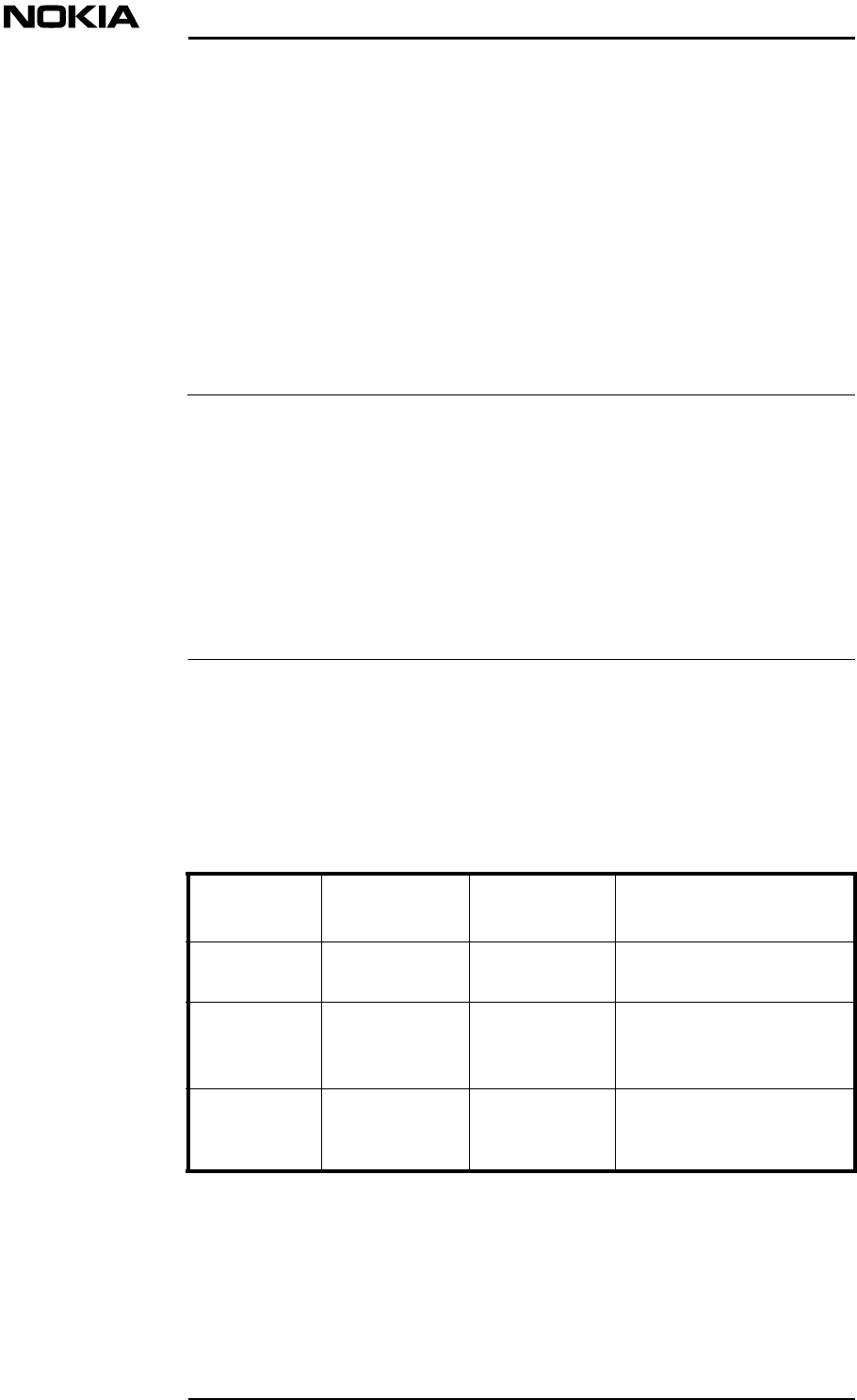
5.1.1 Local Unit
Figure shows the layout of the fibre optical connectors.
Figure 13. Fibre optical connectors of the Local Unit
Table 7. Local Unit connectors
5.2 Remote Unit
The interface connectors of the RU are shown in Table .
RX 1RX 2
RX 4
RX 3
TX 1TX 2
TX 3TX 4
Interface
connector Number of
connectors Connector
type Cable type/diameter
Optical TX or
RX8SC/APC
(female)125 µm single mode
Interface
connector Number of
connectors Connector
type Cable type/diameter
Antenna 2N-type, female 1/2” RF cable
Interfaces and cables
DN00283911 © Nokia Corporation 39 (43)
Issue 2 DRAFT 1 - en Nokia Proprietary and Confidential
Table 8. Remote Unit connectors
Optical TX or
RX2SC/APC
(female)125 µm single mode
External
alarm2Molex(female) -
Interface
connector Number of
connectors Connector
type Cable type/diameter

System Requirements for Installation and Operation
40 (43)© Nokia Corporation DN00283911
Nokia Proprietary and ConfidentialIssue 2 DRAFT 1 - en
Installation equipment
DN00283911 © Nokia Corporation 41 (43)
Issue 2 DRAFT 1 - en Nokia Proprietary and Confidential
6Installation equipment
This section specifies the equipment that is recommended for the installation of
the Nokia InLite, but not included in the Nokia InLite delivery.
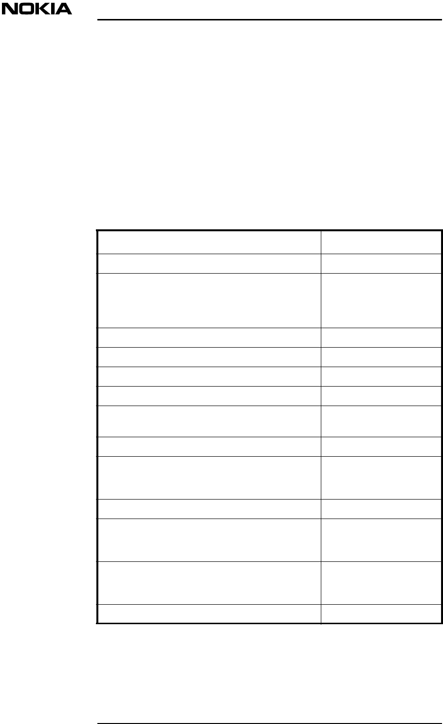
The recommended tools are:
Tool Used for
Torque driver, T10 Torx bit with min. 60 mm shaft Unit retaining screws
Torque driver, 4 mm Allen bit with min. 60 mm
shaftMU mounting screws (5.5
Nm/4.06 ft-lb.)
Ground cable fixing (5.5
Nm/4.06 ft-lb.).
Cable ties Keeping cables tidy
Side cutting pliersCutting cable ties
Splicing machine and toolsConnecting optical fibres
Optical spool (about 500m single mode)Optical measurements
Optical cable cutting machineCutting optical cables to
length
Cleaning kit Cleaning optical fibres
Optical Time Domain Reflectometer (OTDR)Testing optical fibres.
Shows signal trace and
attenuation.
Splice protection tubes Protecting optical splices
LMP cableConnecting the local
management PC to the
MU
Laptop PC (Pentium processor minimum) with
Supervisor Software Version 2.3.2 or higher
installed
Local management
functions
Antistatic wrist strap ESD grounding
System Requirements for Installation and Operation
42 (43)© Nokia Corporation DN00283911
Nokia Proprietary and ConfidentialIssue 2 DRAFT 1 - en
Note
Note
Table 9. Recommended tools and usage
Additional tools/equipment include:
•2 x radio phones for communicating when testing the fibre optic cable
splicing
•Spirit level for checking the horizontal level of the MU and RU
•Tape measure
•Hammer
•Screwdrivers
•Crimping tool for assembling the power supply cable connector
A set of tools needed for assembling the cable connectors is available from Nokia.
•Cable stripper for assembling the power supply cable connector
•Power meter, including a 50 Ohm, 30 W, DC - 2GHz terminator and a set
of 7/16 N male and female RF adapters
The power meter should be a GSM 900/1800 or CDMA/TDMA/GSM 800/1900,
dual band, fully portable RF power meter with: high resolution, analogue/digital
readout and dBm/watt conversion capability
•Labels for labelling the origin and destination of cables
•Screwdriver for assembling the AC cable connector
•Ladder (depending on circumstances on site)
•Scaffolding, if working at height
•Cutter
•Wrenches
•Dynamometric wrench
•Scissors
•Allen keys, sizes 4 and 6 for fixing the MU to the mounting frame
•T20 Torx torque driver for removing and tightening the MU cover top
retaining screws (optional)
•Centre punch for marking hole locations in wall (optional)
•Drill with correct bits for the mounting position and location (if required)
•Extra lighting for splicing work area
•Table for splicing machine
•Set of Allen keys
Installation equipment
DN00283911 © Nokia Corporation 43 (43)
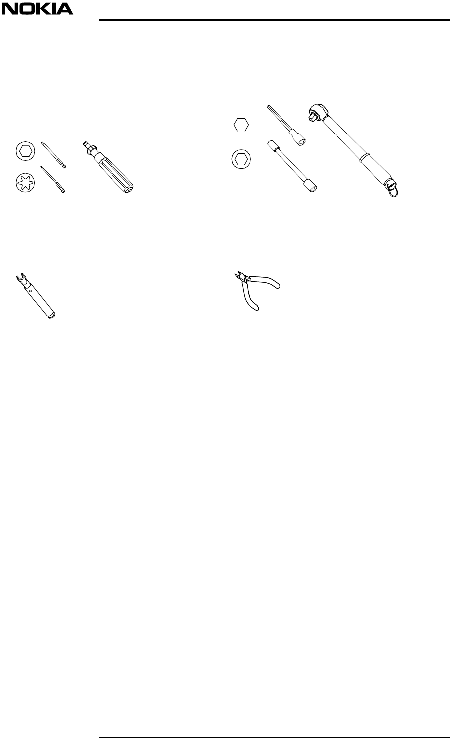
Issue 2 DRAFT 1 - en Nokia Proprietary and Confidential
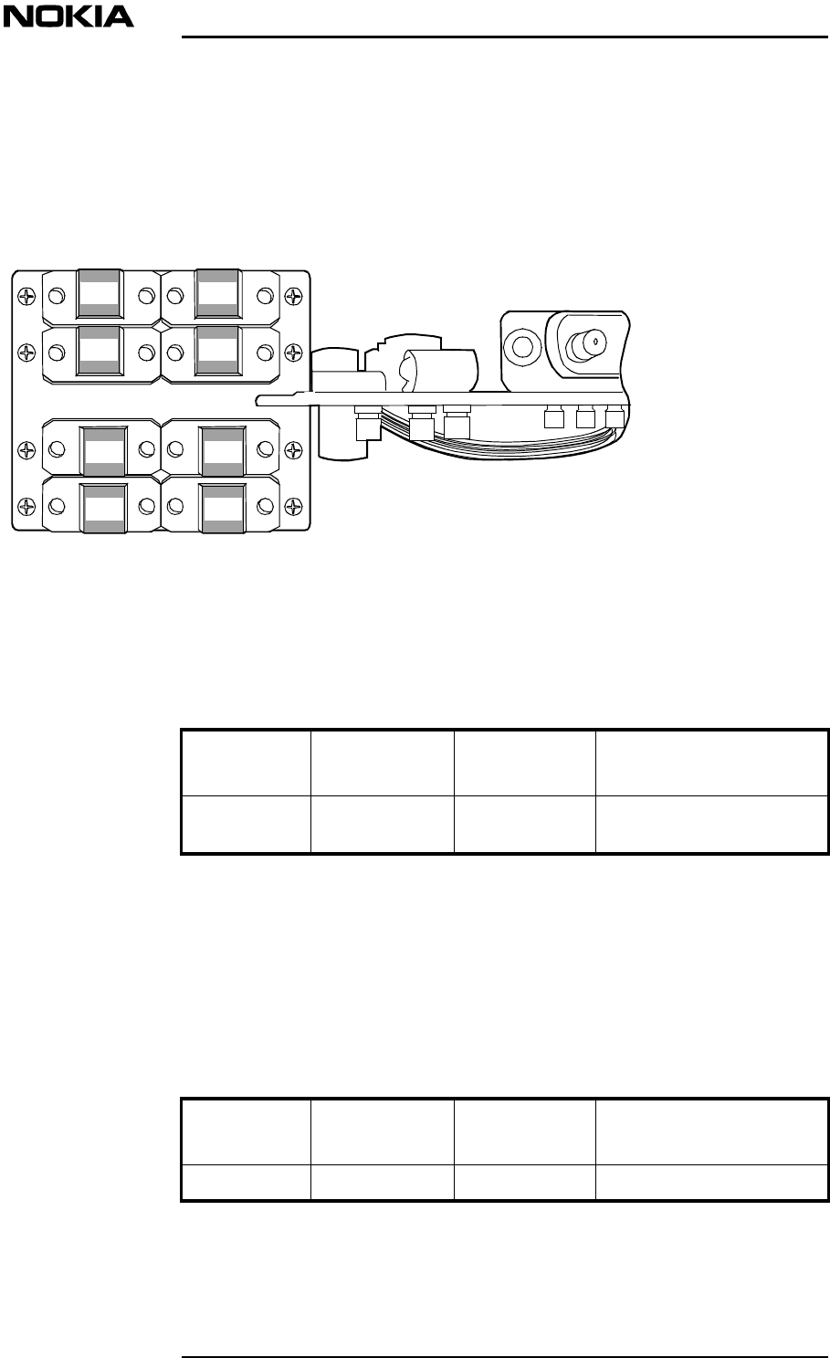
Figure 14. Recommended tools for installing the Nokia InLite
Side-cutting pliers
Torque socket spanner/wrench
(5-20 Nm/3-14 ft-lb)
Torque key
Torque driver (0-6 Nm/0-5 ft-lb)