Nokia Solutions and Networks INLITERU-01 InLite Dual Band Enhancer Remote Unit User Manual Maintenance
Nokia Solutions and Networks InLite Dual Band Enhancer Remote Unit Maintenance
Contents
Maintenance

DN00283717 © Nokia Corporation 1 (26)
Issue 2 DRAFT 1 - en Nokia Proprietary and Confidential
Maintenance
Maintenance
2 (26)© Nokia Corporation DN00283717
Nokia Proprietary and ConfidentialIssue 2 DRAFT 1 - en
The information in this document is subject to change without notice and describes
only the product defined in the introduction of this documentation. This document is
intended for the use of Nokia Networks' customers only for the purposes of the
agreement under which the document is submitted, and no part of it may be
reproduced or transmitted in any form or means without the prior written permission of
Nokia Networks. The document has been prepared to be used by professional and
properly trained personnel, and the customer assumes full responsibility when using it.
Nokia Networks welcomes customer comments as part of the process of continuous
development and improvement of the documentation.
The information or statements given in this document concerning the suitability,
capacity, or performance of the mentioned hardware or software products cannot be
considered binding but shall be defined in the agreement made between Nokia
Networks and the customer. However, Nokia Networks has made all reasonable
efforts to ensure that the instructions contained in the document are adequate and free
of material errors and omissions. Nokia Networks will, if necessary, explain issues
which may not be covered by the document.
Nokia Networks' liability for any errors in the document is limited to the documentary
correction of errors. Nokia Networks WILL NOT BE RESPONSIBLE IN ANY EVENT
FOR ERRORS IN THIS DOCUMENT OR FOR ANY DAMAGES, INCIDENTAL OR
CONSEQUENTIAL (INCLUDING MONETARY LOSSES), that might arise from the
use of this document or the information in it.
This document and the product it describes are considered protected by copyright
according to the applicable laws.
NOKIA logo is a registered trademark of Nokia Corporation.
Other product names mentioned in this document may be trademarks of their
respective companies, and they are mentioned for identification purposes only.
Copyright © Nokia Corporation 2001. All rights reserved.
Hereby, Nokia Corporation, declares that this Nokia InLite is in compliance with
the essential requirements and other relevant provisions of Directive: 1999/5/EC.
The product is marked with the CE marking and Notified Body number according
to the Directive 1999/5/EC
FCC FCC §15.21 - Information to user - The Nokia InLite is used as an intentional
radiated equipment and any changes or modifications on the equipment without
any approval by Nokia could void the user's authority to operate the equipment.
FCC §15.27 b) - Special Accessories - If a device requiring special accessories
is installed by or under the supervision of the party marketing the device, it is the
responsibility of that party to install the equipment using the special accessories.
For equipment requiring professional installation, it is not necessary for the
responsible party to market the special accessories with the equipment. However,
the need to use the special accessories must be detailed in the instruction
manual, and it is the responsibility of the installer to provide and to install the
required accessories.
0523

DN00283717 © Nokia Corporation 3 (26)
Issue 2 DRAFT 1 - en Nokia Proprietary and Confidential
FCC §15.105 - Information to user - This equipment has been tested and found
to comply with the limits for a Class B digital device, pursuant to part 15 of the
FCC Rules. These limits are designed to provide reasonable protection against
harmful interference in a residential installation. This equipment generates, uses
and can radiate radio frequency energy and, if not installed and used in
accordance with the instructions, may cause harmful interference to radio
communications. However, there is no guarantee that interference will not occur
in a particular installation. If this equipment does cause harmful interference to
radio or television reception, which can be determined by turning the equipment
off and on, the user is encouraged to try to correct the interference by one or more
of the following measures:
•Reorient or relocate the receiving antenna.
•Increase the separation between the equipment and receiver.
•Connect the equipment into an outlet on a circuit different from that to which
the receiver is connected.
•Consult the dealer or an experienced radio/TV technician for help.
Maintenance
4 (26)© Nokia Corporation DN00283717
Nokia Proprietary and ConfidentialIssue 2 DRAFT 1 - en
History
Date Version Author Details
22-5-2000 Draft1N. T. Thomas Compilation of a first draft of the User
Manual: installation
13-10-2000 Draft 2T N WilliamsDraft updated to include RF team
comments.
06 - 02 - 2001 Draft 3Indi Liepa Updated after review by Harri Vaananen
23 - 03 - 2001 Issue 1 Brian SearleAdditions and corrections after review
team activity
27 - 07 - 2001 Issue 2 Draft 1Tom DumicIncluded US Type Approval requirements
22 - 08 - 2001 Issue 2 Tom DumicRelease for Product v1.0 US
05 - 09 - 2001 Issue 2, Draft 1Tom DumicDraft for Product v2

About this document
DN00283717 © Nokia Corporation 5 (26)
Issue 2 DRAFT 1 - en Nokia Proprietary and Confidential
1About this document
This document provides instructions for maintaining the InLite. Maintenance
procedures are carried out to ensure the efficient operation of the Nokia InLite
system after it has been installed and commissioned.
Throughout the document, warnings, cautions and notes are given whenever
appropriate.

Maintenance
6 (26)© Nokia Corporation DN00283717
Nokia Proprietary and ConfidentialIssue 2 DRAFT 1 - en
Preventive maintenance
DN00283717 © Nokia Corporation 7 (26)
Issue 2 DRAFT 1 - en Nokia Proprietary and Confidential
2Preventive maintenance
The Nokia InLite system requires a minimum of maintenance and supervision.
Should an alarm condition occur, its location can readily be determined, using the
laptop PC, then quickly corrected.
To ensure the continued integrity of the InLite system, certain maintenance tasks
must be performed at regular periods.
2.1 Periodic checks
Visual inspection and cleaning
Check that the following conditions are satisfied:
1. The Main Unit (MU) is firmly secured in position.
2. The MU is not damaged in any way and that the lock performs its function
correctly.
3. The MU is clean and free from dirt. (Clean the surfaces as necessary.)
4. The green LEDs on in all plug-units inside the MU (i.e., there are no alarm
conditions).
5. Each Remote Unit (RU) is properly secured in its position.
6. The installed RUs are not damaged.
7. The red LED (Fault) indicator on the RU is not lit.
8. The RU is clean and free from dust or dirt. (Clean the surfaces as
necessary.)
9. Exposed cables (RF, optical and power) are not damaged or under stress.
2.2 Action plan
It is recommended that an action plan be prepared if a fault occurs in MU or RUs.
The purpose of this plan is to correct the fault and if necessary, replace any faulty
unit minimal traffic disruption.

Maintenance
8 (26)© Nokia Corporation DN00283717
Nokia Proprietary and ConfidentialIssue 2 DRAFT 1 - en
Consult with the indoor network planners and use the Switch Matrix capability to
reroute services and capacity to other MUs or RUs to reduce or avoid cut in
services or in RF coverage.
Pay attention to the fact that Intelligent Network dedicated services (e.g., GSM
Office, Private Virtual Network) located in a specific area of a building cannot be
relocated.
If it becomes necessary to replace BTS RF cables, contact the Operations and
Maintenance Centre (OMC), advising them of possible internal or external alarms
and asking them to take the related TRXs out of service before starting any repair
activities.
Repair
DN00283717 © Nokia Corporation 9 (26)
Issue 2 DRAFT 1 - en Nokia Proprietary and Confidential
WARNING
3Repair
3.1 Locating faults
Faults in the MU or the Remote Unit can be diagnosed and located using the
Supervisor software application installed on the laptop PC.
All persons who perform operations on this equipment should be advised of
the potential dangers.
Warnings and cautions are provided in Nokia InLite: Warnings and Cautions.
3.1.1 Using the laptop PC
Use the following procedure to connect the laptop PC to the MU and to start the
Supervisor software.
Relevant Warnings and cautions are given in Warnings and Cautions.
Connecting the laptop PC
1. Unlock the MU cover.
2. Holding the cover firmly, carefully push the cover upwards and pull it clear
of the InLite MU.
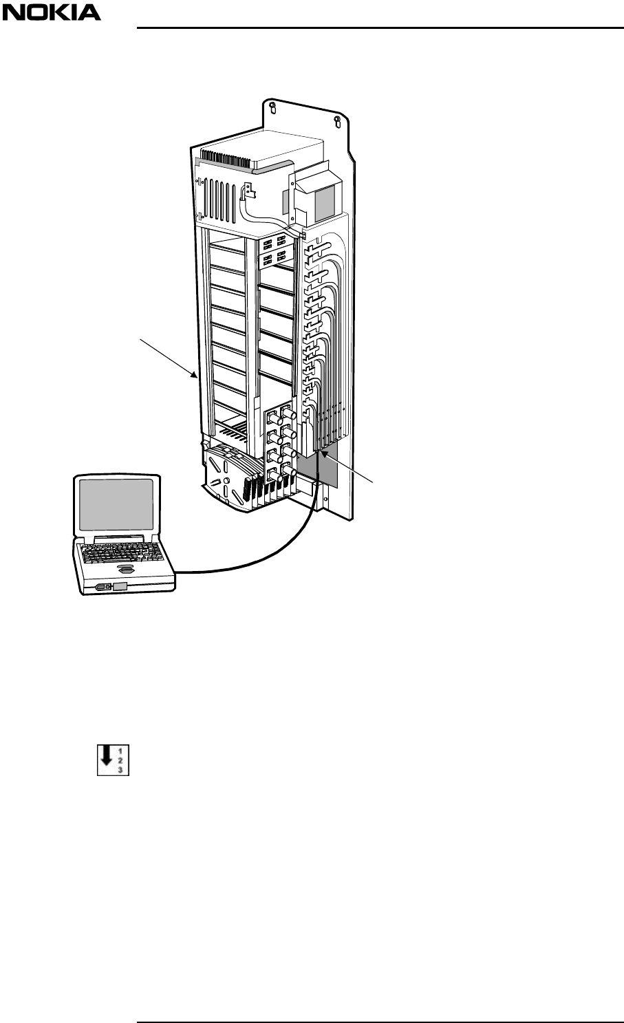
3. Connect the laptop PC to the LMP port on the MU, using the LMP cable as
shown in Figure .
Maintenance
10 (26)© Nokia Corporation DN00283717
Nokia Proprietary and ConfidentialIssue 2 DRAFT 1 - en
Figure 1. Laptop to MU connection
4. Start the laptop PC.
Starting the Supervisor software
1. In Windows, click on the Start button (normally located in the bottom left
hand corner of the screen display.
2. Follow the path:
Start\Programs\Supervisor Ver 1.0.0
or
LMP port
(front connector)
9-way 'D' type
connector
(male)
Laptop P.C (with Supervisor software)
LMP cable
Main Unit
Repair
DN00283717 © Nokia Corporation 11 (26)
Issue 2 DRAFT 1 - en Nokia Proprietary and Confidential
Start\Programs\Supervisor Ver 1.0.1
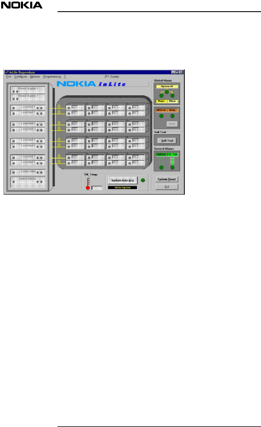
When the software application starts, the main window appears normally
(Figure ).
Figure 2. InLite Supervisor main window
If the Supervisor software application is being invoked for the first time,
however, the Com Port SetUp window will appear ( Figure ) instead of the
main window.
Maintenance
12 (26)© Nokia Corporation DN00283717
Nokia Proprietary and ConfidentialIssue 2 DRAFT 1 - en
Note
Note
Note
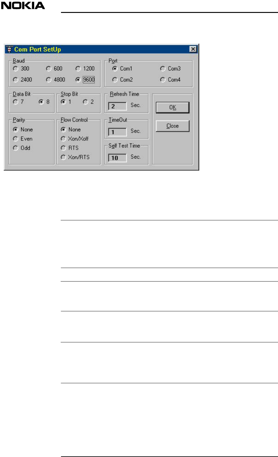
Figure 3. Com Port Setup window
The Nokia default setting is: 9600 Baud, 8NI (8 bit data, no parity bit, 1 stop bit).
If this setting is to be changed, the Com port chosen should be a com port
not used by other peripherals. If the com port chosen is already in use, an error
message is issued telling the operator to choose another port.
The Com Port setup window can also be accessed via the Configure button in the
main window of the Supervisor software.
3. In the main window, click on the System auto Acq button. The Supervisor
software will show any alarms that exist.
It is possible that at power up, the BkUp alarm (BkUp) will be active.
If this alarm is present, click on the BkUp button in the main window, then close
the BkUP window.
For more information about the Supervisor software, refer to the document Nokia
InLite Commissioning
Repair
DN00283717 © Nokia Corporation 13 (26)
Issue 2 DRAFT 1 - en Nokia Proprietary and Confidential
WARNING
3.1.2 Disconnecting the laptop PC
Use this procedure to disconnect the laptop PC after all faults have been located,
diagnosed, corrected and tested.
To disconnect the laptop PC
1. Close the Supervisor software and shut down the laptop PC.
2. Disconnect the laptop PC and LMP cable from the MU.
3. Store the laptop in a secure location.
4. Carefully locate the MU plastic cover over the assembly and push back,
making sure that the cover locking guides are aligned with the back-plate
recesses.
5. Push the cover down to secure it to the back-plate.
6. Lock the MU front cover.
3.2 Correcting faults
All persons who perform operations on this equipment should be advised of
the potential dangers.
General warnings and cautions are provided in Nokia InLite: Warnings and
Cautions.
The following procedure provides general instructions on how to locate, repair
and test a repair.
To locate and correct a fault in the InLite system
1. Connect the laptop PC and start the Supervisor software as described in
Section 3.1.1.
2. Locate the fault, using the Supervisor software.
3. Perform the maintenance procedure relevant to the fault.
4. Check that the fault has been corrected, using the Supervisor Software.
5. Shut down and disconnect the laptop PCas described in Section 3.1.2.
Maintenance
14 (26)© Nokia Corporation DN00283717
Nokia Proprietary and ConfidentialIssue 2 DRAFT 1 - en
WARNING
Caution
3.3 MU
3.3.1 Locating a faulty unit
To locate a faulty unit in the MU
1. Connect the laptop PC as described Section 3.1.1.
2. Start the Supervisor software application.
3. The LED icon of the faulty unit in the Supervisor software window will be
coloured red.
3.3.2 Replacing a faulty unit
Relevant warnings and cautions are given in Nokia InLite: Warnings and
Cautions.
Advise all persons who perform operations on this equipment of the potential
dangers.
To replace a unit in the MU
If the faulty unit is a Local Unit, the fibre optic cables must be disconnected
before the unit is removed.
1. Undo the four captive retaining screws securing the unit to the MU rack.
2. Carefully withdraw the unit from its position in the MU rack, then store the
unit in a safe place.
3. Insert a known good unit into the location vacated by the faulty unit,
making sure that the unit is correctly aligned on its guides and is pushed
firmly back to engage with the mating connector at the rear of the location.
4. Secure the unit in position using the four captive retaining screws.
5. Check that the replacement unit is operating correctly, using the Supervisor
software. The LED icon should be coloured green.
6. Close the Supervisor software and shut down the laptop PC as described in
Section 3.1.2.
7. Refit the MU cover.
Repair
DN00283717 © Nokia Corporation 15 (26)
Issue 2 DRAFT 1 - en Nokia Proprietary and Confidential
Note
WARNING
WARNING
Note
8. Send the faulty unit to Nokia for repair, using the procedure advised by the
local Nokia agent. The unit should be identified and accompanied by a fault
statement.
3.4 Remote Unit
3.4.1 Localising an RU fault
Normally, an RU fault is located with the use of the InLite Supervisor software
application. However, an RU has two LEDs (green and red) that are visible
externally. The LEDs are illuminated when the RU is in a fault state and not
functioning.
An RU fault is identified using the Supervisor software.
The RU LEDs (2) are located under the cable cover of the RU mounting rack. It
is advisable to remove the cable cover so the two LEDs can be seen properly.
3.4.2 Replacing an RU
General warnings and cautions are given in Warnings and Cautions.
3.4.2.1 To replace a faulty RU IP41
Disconnect the power connector from the RU before performing this
procedure.
Shut down the laser in the LU connected to the RU that is to be replaced.
Respect the laser radiation warnings.
Refer to document Installation
1. Connect the laptop PC to the MU as described in Figure .
2. Start the ISMMan software application.

Maintenance
16 (26)© Nokia Corporation DN00283717
Nokia Proprietary and ConfidentialIssue 2 DRAFT 1 - en
3. Go to the Local Unit window of the ISMMan software. Use the ISMMan
software to switch off the DL laser of the relevant LU. The colour of the
LED icon will change to red.
4. Remove the four M3 x 20 fixing screws that secure the cable cover to the
Remote Unit mounting rack.
5. Remove the cable cover.
6. Disconnect the power supply cable from the RU.
7. Disconnect the antenna cables from the RU.
8. Disconnect carefully the two fibre optic cables from the RU and fit
protective caps to the ends of the fibre optic cables.
9. Remove the five M3 x 8 fixing screws that secure the RU to its mounting
rack.
10. Lift the RU up and off its mounting rack, then store in a safe place.
11. Obtain a known good RU and carefully place it on the mounting rack,
pushing it down gently to secure it in position.
12. Secure the RU to the mounting rack using five fixing screws.
13. Connect the antenna cables to the RU in their correct positions.
14. Remove the protective caps from the ends of the fibre optic cables and
connect carefully the two fibre optic cables to the RU. Store the protective
caps in a safe place.
15. Secure the cable cover of the RU mounting rack with four screws.
16. Connect the power supply cable to the RU power supply connector.
17. Where applicable, set the RU power to ON at the mains switchboard or at
the CPSU or insert power supply plug to the socket.
18. At the location of the replacement RU, verify that its power LED is lit
(green) and the red FAULT LED is unlit (dark) on the RU.
19. Use the supervisor software to check that the alarm has disappeared.
20. Send the faulty RU, suitably identified and fault symptom(s) stated, to
Nokia for repair, using the procedure advised by the local Nokia agent.
Repair
DN00283717 © Nokia Corporation 17 (26)
Issue 2 DRAFT 1 - en Nokia Proprietary and Confidential
WARNING
WARNING
Note
3.4.2.2 To replace a faulty RU IP53
Disconnect the power connector from the RU before performing this
procedure.
Shut down the laser in the LU connected to the RU that is to be replaced.
Respect the laser radiation warnings.
Refer to document Installation
1. Connect the laptop PC to the MU as described in Figure .
2. Start the ISMMan software application.
3. Go to the Local Unit window of the ISMMan software. Use the ISMMan
software to switch off the DL laser of the relevant LU. The colour of the
LED icon will change to red.
4. Remove one M6 x 40 screw on top of the cover which secures the enclosure
cover to the wall.
5. Remove the cover by sliding it upwards along the bars on both sides of the
backplate.
6. Disconnect the power supply cable from the RU.
7. Disconnect the antenna cables from the RU.
8. Disconnect carefully the two fibre optic cables from the RU and fit
protective caps to the ends of the fibre optic cables.
9. Remove the five M3 x 8 fixing screws which secure the RU to the
backplate of the enclosure.
10. Lift the RU up and off the backplate, then store it in a safe place.
11. Obtain a known good RU and carefully place it on the mounting rack,
pushing it down gently to secure it in position.
12. Secure the RU to the mounting rack using five fixing screws.
13. Connect the antenna cables to the RU in their correct positions.
14. Remove the protective caps from the ends of the fibre optic cables and
carefully connect the two fibre optic cables to the RU. Store the protective
caps in a safe place.
15. Connect the power supply cable to the RU power supply connector.
Maintenance
18 (26)© Nokia Corporation DN00283717
Nokia Proprietary and ConfidentialIssue 2 DRAFT 1 - en
WARNING
WARNING
Note
16. Where applicable, set the RU power to ON at the mains switchboard or at
the CPSU.
17. At the location of the replacement RU, verify that its power LED is lit
(GREEN) and the red FAULT LED is unlit (dark) on the RU.
18. Use the ISMMan software to check that the alarm has disappeared.
19. Replace the cover by sliding it downwards from top of the backplate along
the bars on both sides of it.
20. Secure the cover to the wall using one fixing screw.
21. Send the faulty RU, suitably identified and fault symptom(s) stated, to
Nokia for repair, using the procedure advised by the local Nokia agent.
3.4.2.3 To replace a faulty RU IP64
Disconnect the power connector from the RU before performing this
procedure.
Shut down the laser in the LU connected to the RU that is to be replaced.
Respect the laser radiation warnings.
Refer to document Installation
1. Connect the laptop PC to the MU as described in Figure .
2. Start the ISMMan software application.
3. Go to the Local Unit window of the ISMMan software. Use the ISMMan
software to switch off the DL laser of the relevant LU. The colour of the
LED icon will change to red.
4. Remove the 10 M5 x 16 screws on top of the cover which secure the cover
to the enclosure, and open the cover.
5. Disconnect the power supply cable from the RU.
6. Disconnect the antenna cables from the RU.
7. Disconnect carefully the two fibre optic cables from the RU and fit
protective caps to the ends of the fibre optic cables.
8. Remove the wing screw from the splice box and open the splice box.
9. Very carefully remove the fibre optic cables from the splice holder in order
not to break the fibre optic cables.

Repair
DN00283717 © Nokia Corporation 19 (26)
Issue 2 DRAFT 1 - en Nokia Proprietary and Confidential
Caution
10. Very carefully draw the optic cables out of the enclosure through the hole
they are fitted into the enclosure.
11. Remove the four M6 x 40 fixing screws which secure the enclosure to the
wall.
RU IP64 weighs 11 kg so be very careful while removing the screws.
12. Lift the RU off the wall, then store in a safe place.
13. Obtain a known good RU and carefully place it on the wall.
14. Carefully support the RU and secure it to the wall using four fixing screws.
15. Very carefully draw the optic cables into the enclosure through the same
hole they were removed.
16. Very carefully arrange the fibre optic cables in the splice holder, close the
splice box and tighten with the wing screw.
17. Remove the protective caps from the ends of the fibre optic cables and
carefully connect the two fibre optic cables to the RU. Store the protective
caps in a safe place.
18. Connect the antenna cables to the RU in their correct positions.
19. Connect the power supply cable to the RU power supply connector.
20. Where applicable, set the RU power to ON at the mains switchboard or at
the CPSU.
21. At the location of the replacement RU, verify that its power LED is lit
(GREEN) and the red FAULT LED is unlit (dark) on the RU.
22. Use the ISMMan software to check that the alarm has disappeared.
23. Send the faulty RU, suitably identified and fault symptom(s) stated, to
Nokia for repair, using the procedure advised by the local Nokia agent.
3.5 Cabling
Faulty RF cables and FO cables should be replaced.

Maintenance
20 (26)© Nokia Corporation DN00283717
Nokia Proprietary and ConfidentialIssue 2 DRAFT 1 - en
System upgrades
DN00283717 © Nokia Corporation 21 (26)
Issue 2 DRAFT 1 - en Nokia Proprietary and Confidential
4System upgrades
4.1 Supervisor software
To upgrade the Supervisor Software
The procedure installs a new version of the Supervisor Software.
1. Check the version of the new CD-ROM
2. Insert the CD-ROM and run the “setup” file.
4.2 System configuration
An InLite system can comprise up to eight LUs and each LU can handle up to four
RUs. The actual number of RUs installed can therefore vary between one and 32.
The configuration of the system is quite flexible and can be expanded or
contracted by adding and removing LUs and RUs.
4.2.1 Adding a Remote Unit
Full instructions for adding a Remote Unit to an InLite system are given in Nokia
InLite Installation
4.2.2 Removing a Remote Unit
Full instructions for removing a Remote Unit from an InLite system are given in
Nokia InLite Installation

Maintenance
22 (26)© Nokia Corporation DN00283717
Nokia Proprietary and ConfidentialIssue 2 DRAFT 1 - en
Fault finding and clearing
DN00283717 © Nokia Corporation 23 (26)
Issue 2 DRAFT 1 - en Nokia Proprietary and Confidential
5Fault finding and clearing
5.1 Fault finding
Fault finding is arrange in two categories:
1. Coverage
2. Alarm indication.
5.1.1 Loss of coverage
The following table defines the extent of loss of coverage and the possible cause
of this loss of coverage.
Loss of
coverage Possible cause
TotalThe BTS is not connected
The BTS is switched off
Power supply is not available
Centralised PSU fault
Some areas onlyRelated RU power supply is not available
The RF/optic cable is faulty
The RF/fibre optic connector is
damaged/dirty
The RU for that area is faulty

Maintenance
24 (26)© Nokia Corporation DN00283717
Nokia Proprietary and ConfidentialIssue 2 DRAFT 1 - en
Table 1. Loss of Coverage
5.1.2 Alarms
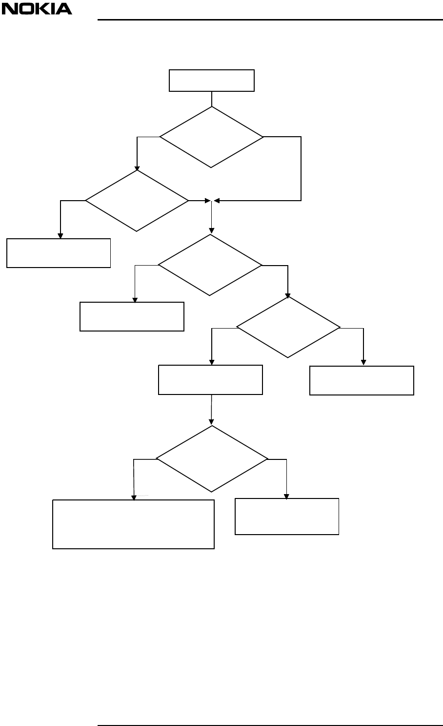
The following fault finding algorithm shows a procedure for interpreting alarms
and methods for clearing them.
Fault finding and clearing
DN00283717 © Nokia Corporation 25 (26)
Issue 2 DRAFT 1 - en Nokia Proprietary and Confidential
Figure 4. Fault finding flow chart
Alarm ON
Local Unit
Alarm?
Is it a
downlink or
uplink alarm?
YESNO
ULDL
The Local Unit
is faultyYESNO
Remote Unit
Alarm?
The laser is faulty
or under stress Is there an
input signal?
Connect an input
signal to the RU
YESNO
The fault is
in the fibre optic cable
Are the optical
connectors clean?
The fibre optic cable is either broken
or the splices are not perfect.
OTDR action is required
Clean the optical
connectors
YESNO
Maintenance
26 (26)© Nokia Corporation DN00283717
Nokia Proprietary and ConfidentialIssue 2 DRAFT 1 - en
Note
5.2 Cleaning optical connectors
An optical connector is basically a lens, and its performance can be degraded by
dust particles, finger grease and scratches.
The surface of connector ferrule can be inspected by means of a microscope.
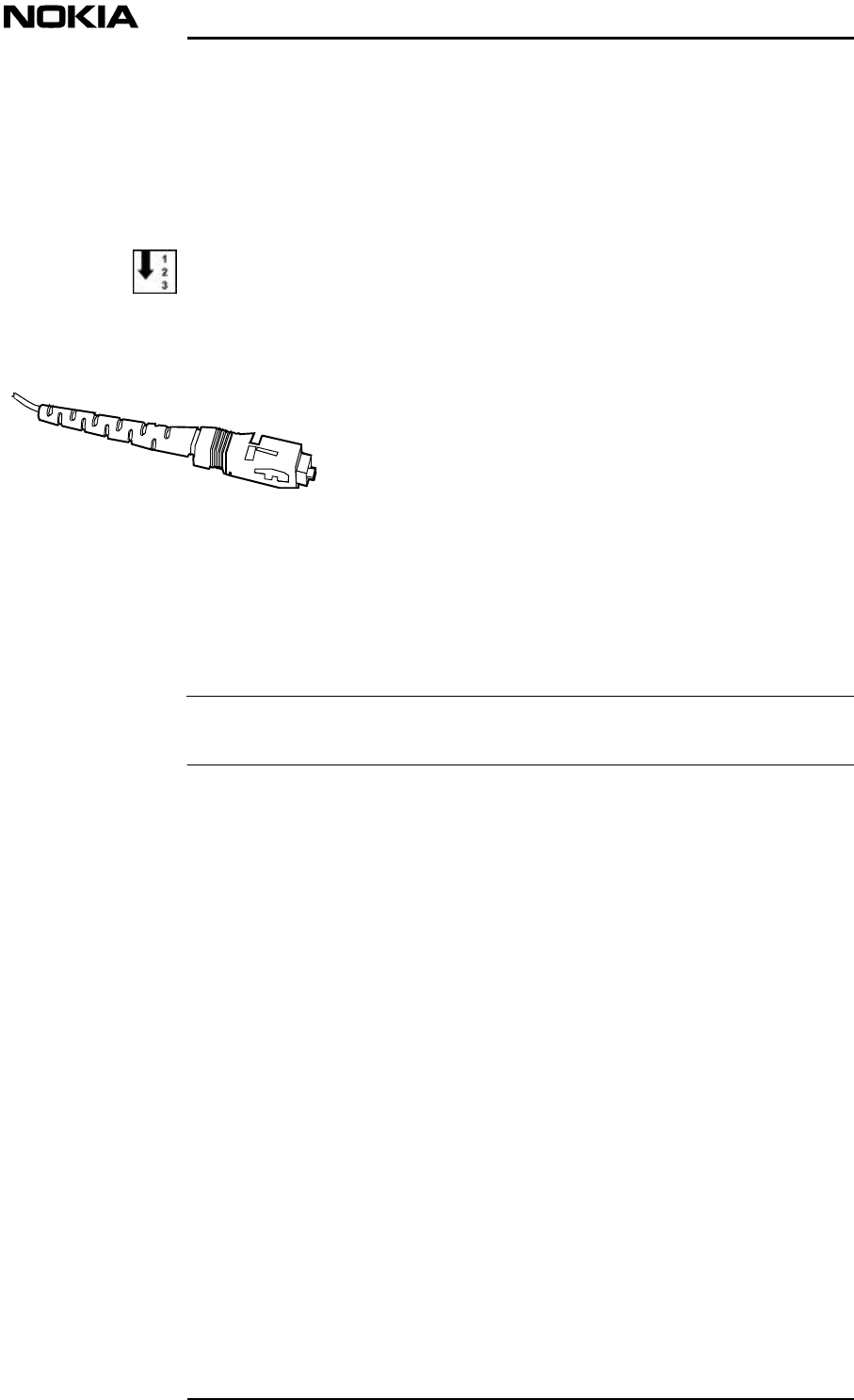
To clean an optical connector
1. Open the connector.
Figure 5. SC/APC male connector
2. Apply a drop of cleaning liquid (pure alcohol) to the edge of the ferrule,
then clean and dry it carefully with a soft tissue, using a circular movement.
Always use one tissue per cleaning activity.
3. Remove any residue particles using a clean, dry air source.
4. Before re-inserting the connector, clean the adapter by applying a drop of
cleaning liquid to the centre hole and removing it immediately, using a
clean, dry air source.
5. Re-insert the connector into the adapter, without the ferrule making any
physical contact with fingers or any other object or surface.