Nokia Solutions and Networks INLITERU-01 InLite Dual Band Enhancer Remote Unit User Manual Warnings and Cautions
Nokia Solutions and Networks InLite Dual Band Enhancer Remote Unit Warnings and Cautions
Contents
- 1. Alarm Description
- 2. Maintenance
- 3. System Requirements
- 4. Warnings and Cautions
- 5. Revised Warnings Page
- 6. Installation
Warnings and Cautions

DN00204118 © Nokia Corporation 1 (22)
Issue 3- 0 en Nokia Proprietary and Confidential
Warnings and Cautions
Warnings and Cautions
2 (22)© Nokia Corporation DN00204118
Nokia Proprietary and ConfidentialIssue 3- 0 en
The information in this document is subject to change without notice and describes
only the product defined in the introduction of this documentation. This document is
intended for the use of Nokia Networks' customers only for the purposes of the
agreement under which the document is submitted, and no part of it may be
reproduced or transmitted in any form or means without the prior written permission of
Nokia Networks. The document has been prepared to be used by professional and
properly trained personnel, and the customer assumes full responsibility when using it.
Nokia Networks welcomes customer comments as part of the process of continuous
development and improvement of the documentation.
The information or statements given in this document concerning the suitability,
capacity, or performance of the mentioned hardware or software products cannot be
considered binding but shall be defined in the agreement made between Nokia
Networks and the customer. However, Nokia Networks has made all reasonable
efforts to ensure that the instructions contained in the document are adequate and free
of material errors and omissions. Nokia Networks will, if necessary, explain issues
which may not be covered by the document.
Nokia Networks' liability for any errors in the document is limited to the documentary
correction of errors. Nokia Networks WILL NOT BE RESPONSIBLE IN ANY EVENT
FOR ERRORS IN THIS DOCUMENT OR FOR ANY DAMAGES, INCIDENTAL OR
CONSEQUENTIAL (INCLUDING MONETARY LOSSES), that might arise from the
use of this document or the information in it.
This document and the product it describes are considered protected by copyright
according to the applicable laws.
NOKIA logo is a registered trademark of Nokia Corporation.
Other product names mentioned in this document may be trademarks of their
respective companies, and they are mentioned for identification purposes only.
Copyright © Nokia Corporation 2001. All rights reserved.
Hereby, Nokia Corporation, declares that this Nokia InLite is in compliance with
the essential requirements and other relevant provisions of Directive: 1999/5/EC.
The product is marked with the CE marking and Notified Body number according
to the Directive 1999/5/EC
FCC FCC §15.21 - Information to user - The Nokia InLite is used as an intentional
radiated equipment and any changes or modifications on the equipment without
any approval by Nokia could void the user's authority to operate the equipment.
FCC §15.27 b) - Special Accessories - If a device requiring special accessories
is installed by or under the supervision of the party marketing the device, it is the
responsibility of that party to install the equipment using the special accessories.
For equipment requiring professional installation, it is not necessary for the
responsible party to market the special accessories with the equipment. However,
the need to use the special accessories must be detailed in the instruction
manual, and it is the responsibility of the installer to provide and to install the
required accessories.
0523

DN00204118 © Nokia Corporation 3 (22)
Issue 3- 0 en Nokia Proprietary and Confidential
FCC §15.105 - Information to user - This equipment has been tested and found
to comply with the limits for a Class B digital device, pursuant to part 15 of the
FCC Rules. These limits are designed to provide reasonable protection against
harmful interference in a residential installation. This equipment generates, uses
and can radiate radio frequency energy and, if not installed and used in
accordance with the instructions, may cause harmful interference to radio
communications. However, there is no guarantee that interference will not occur
in a particular installation. If this equipment does cause harmful interference to
radio or television reception, which can be determined by turning the equipment
off and on, the user is encouraged to try to correct the interference by one or more
of the following measures:
•Reorient or relocate the receiving antenna.
•Increase the separation between the equipment and receiver.
•Connect the equipment into an outlet on a circuit different from that to which
the receiver is connected.
•Consult the dealer or an experienced radio/TV technician for help.
Warnings and Cautions
4 (22)© Nokia Corporation DN00204118
Nokia Proprietary and ConfidentialIssue 3- 0 en
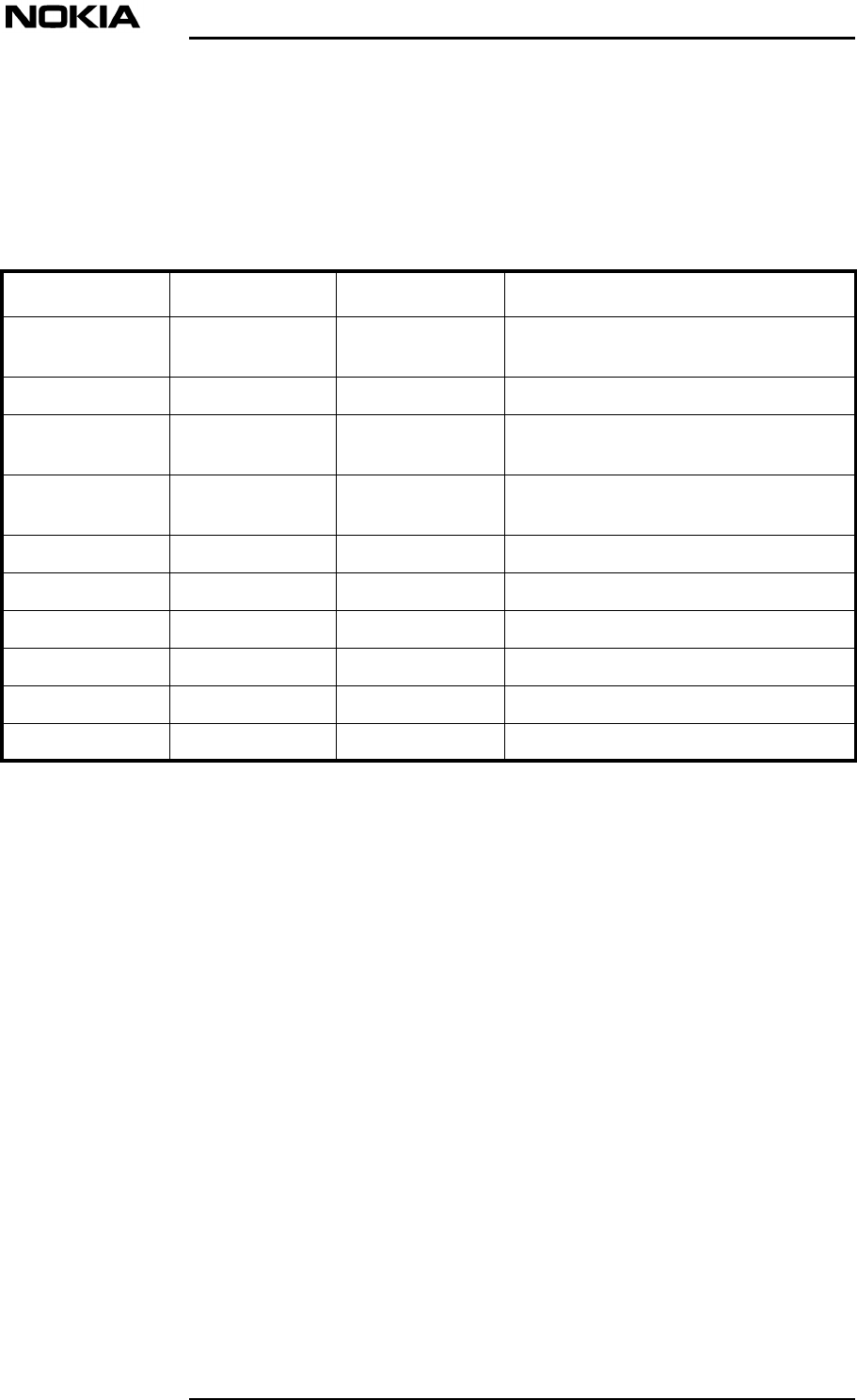
History
Date Version Author Details
9 - 05 - 2000 Draft 1Norman T.
Thomas Initial compilation of document
24 - 10 - 2000 Draft 2Tyrone WilliamsRevised draft
09 - 01- 2001 Draft 3Indi Liepa Revised after subject matter expert
review
26 - 01 - 2001 Draft 4Indi Liepa Revised after Tekmar visit by Harri
Vaananen.
29 - 01 - 2001 Draft 5Indi Liepa Updated after final review by Harri.
9 - 02 - 2001 Issue 1, Draft 6Indi Liepa Final review by Harri.
18 - 07 - 2001 Issue 2, Draft 1Tom DumicIncluded US Type Approval information
22 - 08 - 2001 Issue 2 Tom DumicRelease for Product v1.0.1
05 - 09 - 2001 Issue 2, Draft 1Tom DumicDraft for Product v2
10 - 10 - 2001 Issue 3 Tom DumicRelease for Product v2
About this document
DN00204118 © Nokia Corporation 5 (22)
Issue 3- 0 en Nokia Proprietary and Confidential
WARNING
Caution
1About this document
This document details the safety precautions to be followed when working with
the Nokia InLite. Instructions in Installation, Commissioning and Maintenance
must be followed when installing the Nokia InLite and performing any
commissioning or maintenance on it. Failure to follow these instructions may be
dangerous to the installation, commissioning and maintenance personnel.
1.1 Safety guidelines
The safety guidelines are designed as follows:
•Warnings alert the reader to dangers which may cause loss of life, physical
injury or ill health in any form. The symbol denoting a warning is presented
below.
This is a warning!
•Cautions are used to denote possible damage to equipment but not dangers
to personnel. The symbol denoting a caution is presented below.
This is a caution!

Warnings and Cautions
6 (22)© Nokia Corporation DN00204118
Nokia Proprietary and ConfidentialIssue 3- 0 en
Warnings
DN00204118 © Nokia Corporation 7 (22)
Issue 3- 0 en Nokia Proprietary and Confidential
WARNING
WARNING
2 Warnings
2.1 Personnel
Installation, commissioning and maintenance measures concerning any Nokia
equipment may be performed only by trained and authorized personnel. The
Nokia InLite must be installed so that only the authorized personnel have access
to its sensitive parts.
Always prevent unauthorized personnel from accessing the Nokia InLite.
2.2 Dangerous voltage
Potentially lethal voltage is present within this system. For more information on
grounding and on the power supply, refer to System Requirements for Installation
and Operation.
Disconnect the Main Unit (MU) from the mains power supply before
removing the cable connection cover of the Power Supply Unit (PSU).
The warning label shown in Figure 1 is displayed on the power supply cover:
Warnings and Cautions
8 (22)© Nokia Corporation DN00204118
Nokia Proprietary and ConfidentialIssue 3- 0 en
WARNING
WARNING
WARNING
WARNING
WARNING
Figure 1. Power supply dangerous voltage warning label
Make sure that applicable high voltage safety precautions are taken before
attempting to work on the system with the power connected!
Potentially lethal voltages can be induced if the equipment is not grounded
correctly. Ensure that all ground connections are secure and non-removable!
A current plug with ground connection is not sufficient as it can be pulled off.
Therefore, the grounding should be fixed.
Connect the MU to the main grounding busbar of the site! Electrical currents
from power and communication cables is dangerous.
Ensure that the ground connection is established before an AC power outlet
is connected to the MU! Ensure that the ground connection is removed only
110/220VAC
PART INSIDE
REMOVE THE COVER ONLY
WHEN THE EQUIPMENT IS
DISCONNECTED FROM MAINS
Warnings
DN00204118 © Nokia Corporation 9 (22)
Issue 3- 0 en Nokia Proprietary and Confidential
WARNING
WARNING
WARNING
after the AC power outlet is disconnected!
Do not rely on the power switch alone to isolate a supply. Unplug the power
supply cable from the mains socket if possible.
2.3 Weight
The MU weighs 16.5 kg (33 lb.) without the cover and mounting frame.
The three types of Remote Unit (RU) vary in weight between 1.7 kg (3.8 lb)
and 11 kg (24.25 lb).
The Centralised Power Supply Unit (CPSU) weighs 12.5 kg (27.5 lb).
2.4 Safety and precautions for lasers
The optical transmitter used in the laser which is used in the Nokia InLite system
contains an optical transmitter which has a power level classification of 3A as
defined in EN 60825 (norm). This classification is not considered to be a health
hazard.
When working with the optical connectors, check that the DL laser on the LU is
switched off.
Never look directly at the internal optic connector exit of the transmitter
apparatus when it is switched on. The wavelength of the laser is not visible to
the human eye, which means that long-term damage will not immediately be
known.
The symbol shown in Figure 2 denotes an aperture which is the source of invisible
radiation.
Warnings and Cautions
10 (22)© Nokia Corporation DN00204118
Nokia Proprietary and ConfidentialIssue 3- 0 en
Note
Figure 2. Source of invisible radiation warning label
The symbol shown in Figure 3 denotes a source of laser radiation.
Figure 3. Laser radiation warning label (Class 3A)
The LU is classified as a Class 1 laser product. The RU is classified as a Class 3A
laser product.
2.5 Electromagnetic fields and RF power
The antenna connected to the RU generates electromagnetic radiation, which can
exceed safety levels very close to the antennas. Observe the general guidelines
presented in Section 2.5.1, and apply the minimum distance calculation formula
presented in Section 2.5.2.
LASER RADIATION
DO NOT STARE INTO THE BEAM OR VIEW
DIRECTLY WITH OPTICAL INSTRUMENTS
-CLASS 3A LASER PRODUCT
Warnings
DN00204118 © Nokia Corporation 11 (22)
Issue 3- 0 en Nokia Proprietary and Confidential
WARNING
WARNING
WARNING
2.5.1 General guidelines
The antenna generates electromagnetic radiation which can exceed safety
levels when a person is working in very close proximity to the antennas.
Observe the minimum distance precautions shown in Table 1 when working
in close proximity to an antenna operating at full power.
Do not install the MU, RUs or the antennas in areas where there is a potential
risk for interference with inadequately shielded medical equipment such as
hearing aids, life support devices or other electrically or magnetically
sensitive devices.
When installing the MU, RUs or its antennas, the emission of other antennas
nearby has to be known beforehand so that ambient emissions can be
managed properly.
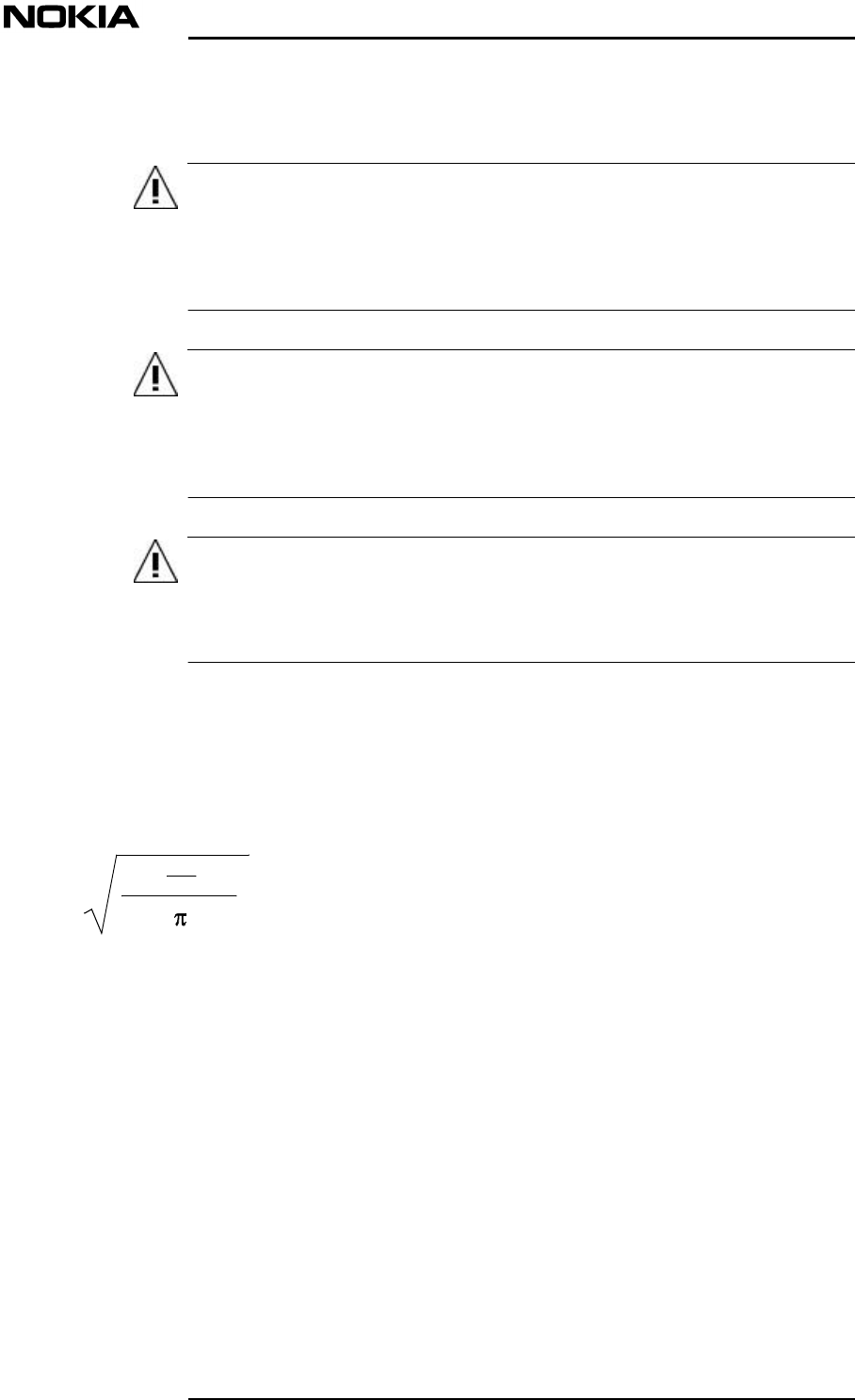
2.5.2 Formula for minimum safety distances
This section presents the formula for calculating the minimum safety distances
using the specifications of the particular antenna.
Figure 4. Formula for calculating minimum safety distance (rmin)
The equatio in Figure includes the following factors:
•G is the antenna gain (in dB) compared to isotropically radiating antenna
•P is the power measured at the antenna port of RU (W)
•L is the total loss (in dB) between the antenna port of RU and the antenna
input
•S is the maximum allowed power density in air (W/m2)
r
min
=
S
4
10 P
(G-L)
10
Warnings and Cautions
12 (22)© Nokia Corporation DN00204118
Nokia Proprietary and ConfidentialIssue 3- 0 en
Note
2.5.3 Safety distance calculation examples
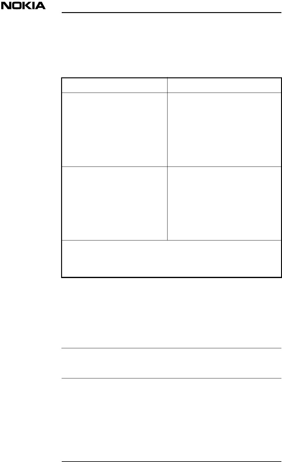
Table describes how the minimum distances for controlled and uncontrolled
environments are calculated.
Table 1. Description for distance calculations in controlled and uncontrolled
environments
Using the formula for minimum safety distances and the appropriate information
for each factor, safety distances can be calculated as in the following calculations
(Table 2) related to a particular environment.
Some of the sample distances in Table 2 are still not available, but will be
available with the full release of the UM.
Limit Description
Minimum Distance in Controlled
Environments*The minimum distances are calculated
using the reference levels for power
density as presented in the CENELEC
prestandard; f/40W/m2, in the
frequency range 400 to 2000MHz,
averaged over any 6 min. time interval.
This is in agreement with other
guidelines (IEEE/ANSI, IRPA, NCRP,
FCC) or stricter.
Minimum Distance in Uncontrolled
Environments*The minimum distances are calculated
using the reference levels for power
density as presented in the CENELEC
prestandard; f/200W/m2, in the
frequency range 400 to 2000MHz,
averaged over any 6 min. time interval.
This is in agreement with other
guidelines (IEEE/ANSI, IRPA, NCRP,
FCC) or stricter.
* Controlled environments refer to locations where there is exposure to
persons aware of the potential exposure. Uncontrolled environments refer to
locations where there is exposure to persons not aware of the potential
exposure and who have no control over it.
Warnings
DN00204118 © Nokia Corporation 13 (22)
Issue 3- 0 en Nokia Proprietary and Confidential
WARNING
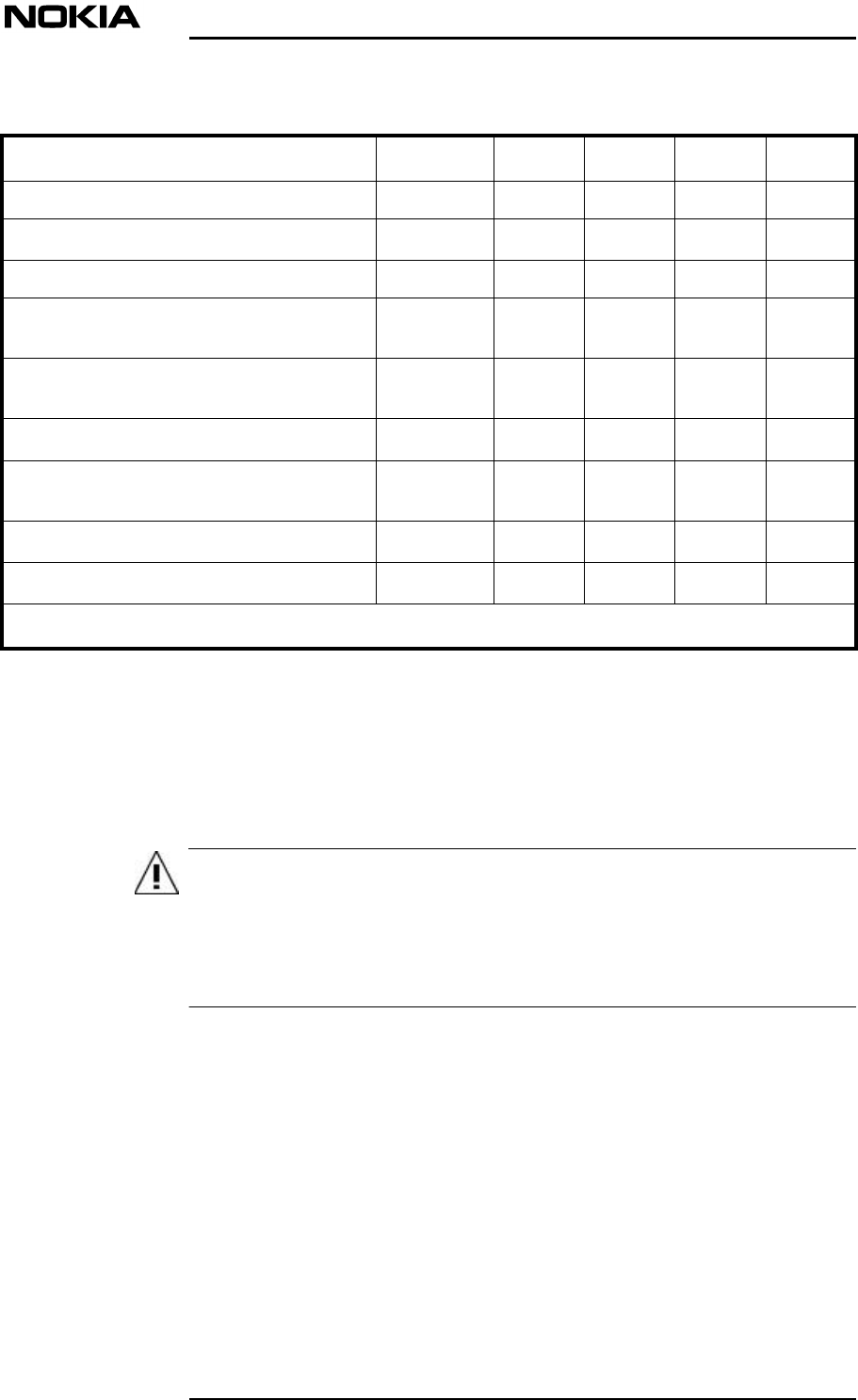
Table 2. Safety distance calculation sample
2.6 Test equipment
Before connecting test equipment to TRX ports or RU antenna ports, check
that 5 VDC voltage does not damage the equipment.
If there is a risk of damage, use a Bias-T between the test equipment and the
aforementioned ports to prevent damage.
The warning symbol shown in Figure 5 denotes a voltage warning.
Factor Unit 800 900 1800 1900
Frequencyf [MHz]800 900 1800 1900
Maximum TX powerPout [W]0.015 0.015
Minimum losses: cableL [dB]1 1
Maximum antenna gain (dependent on
user choices)G [dB]10 10
Maximum number of TRXs/antenna
(dependent on user choices)N2 2
Power Density / Controlled environment*S [W/m2]22.50 45
Power Density / Uncontrolled
environment*S [W/m2]4.5 9
Controlled environment rmin [m]0.02 m0.014 m
Uncontrolled environment rmin [m]0.04 m0.03 m
* CENELEC prestandard ENV50166-2
Warnings and Cautions
14 (22)© Nokia Corporation DN00204118
Nokia Proprietary and ConfidentialIssue 3- 0 en
WARNING
Figure 5. Voltage warning symbol
2.7 TRX input power
The power input from a BTS/TRX connected to the MU must not exceed 33
dBm (2 W).
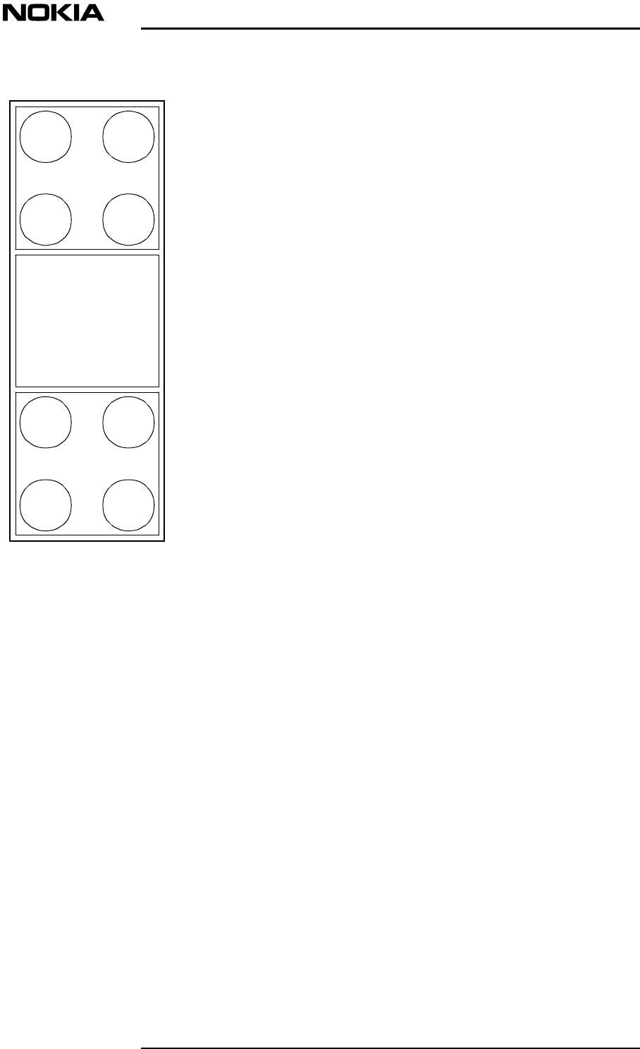
The warning label shown in Figure 6 denotes the input power warning.
5VDC
Warnings
DN00204118 © Nokia Corporation 15 (22)
Issue 3- 0 en Nokia Proprietary and Confidential
Figure 6. Input power warning symbol
BTS1
TRX1TRX2
TRX3TRX4
TRX5TRX6
TRX7TRX8
BTS 2
+33 dBm (2W)
MAX INPUT POWER
+5VDC on connectors
WARNING

Warnings and Cautions
16 (22)© Nokia Corporation DN00204118
Nokia Proprietary and ConfidentialIssue 3- 0 en
Cautions
DN00204118 © Nokia Corporation 17 (22)
Issue 3- 0 en Nokia Proprietary and Confidential
Caution
Caution
Caution
3Cautions
3.1 Handling of MU, RUs and the CPSU
3.1.1 Storage and transportation
During storage and transportation, the MU, RUs and the CPSU (if used) must
remain in the original packaging to:
•Avoid mechanical damage
•Maintain traceability
•Protect the units against static electricity (ESD precaution).
Handle the MU, RUs and the CPSU (if used) with care. Do not drop the product
or the package containing it.
3.1.2 Weight
Persons in charge of the transportation and installation of the MU and RUs must
note that a fully equipped MU (without the cover and mounting frame) weighs
16.5 kg (33 lb.) and the three types of RUs vary in weight between 1.7 kg (3.8 lb)
and 11 kg (24.25 lb).
If a CPSU is used, its weight is 12.5 kg (27.5 lb).
Warnings and Cautions
18 (22)© Nokia Corporation DN00204118
Nokia Proprietary and ConfidentialIssue 3- 0 en
Caution
Caution
Caution
Caution
Caution
3.1.3 Handling the MU
Do not lift the MU by the splice cassette box because the cassette or the cassette
box may break.
Take care not to damage the door switch of the MU when lifting the MU.
3.1.4 Installation of the MU, CPSU and the RUs
Installation of the MU and CPSU above a height of 2 meters is not recommended
due to the difficulties of installing and maintaining the units above this height.
Personnel who are installing the MU, CPSU and the RUs should be informed
about the possible risks and safety measures when elevated. The use of an air
platform for installations of RUs at height is recommended.
3.1.5 Grounding
The MU may receive damaging overvoltages through the RF jumper cable from
the BTS or via power supply lines.
Sufficient protective grounding is required. A current power plug with ground
connection is not sufficient: the grounding of the MU must be based on a fixed
grounding cable.
3.1.6 Electrostatic discharge protection
Always wear a close-fitting antistatic wrist strap around your uncovered wrist
when handling the plug-in units of the MU!

Cautions
DN00204118 © Nokia Corporation 19 (22)
Issue 3- 0 en Nokia Proprietary and Confidential
The MU contains Electrostatic Sensitive Devices (ESD) label and stud, which
means that they may be permanently damaged by electrostatic discharges
encountered in routine handling, testing and transportation. The MU is labelled
with an electrostatic sensitive device symbol as shown in Figure 7.
Figure 7. Electrostatic sensitive device label
Electrostatic discharges are caused by direct contact or by an electrostatic field. If
a charged body approaches an electrically conducting surface, the acquired
potential is discharged. An equalizing current can then flow in the associated
circuitry and generate permanently damaging voltages by induction. The human
body should be grounded at the same potential as the component or equipment
being handled. A wrist strap creates an equipotential electrical connection
between the object and the human.
The MU has a grounding point (ESD stud) to which a wrist strap must be
connected, as seen in Figure 8.

Warnings and Cautions
20 (22)© Nokia Corporation DN00204118
Nokia Proprietary and ConfidentialIssue 3- 0 en
Caution
Figure 8. Wrist strap grounding connection
3.2 Nokia InLite power supply
To protect the MU, RU and CPSU from overvoltages, the use of a transient
overvoltage circuit breaker is recommended.
ESD stud
Wrist strap
Cautions
DN00204118 © Nokia Corporation 21 (22)
Issue 3- 0 en Nokia Proprietary and Confidential
Caution
Caution
Caution
Caution
Caution
3.2.1 MU
3.2.1.1 MU AC power supply
Ensure the correct polarity. Incorrect polarity causes damage to the equipment.
The MU power switch does not disconnect the equipment from the power
network.
The separate main switch on the site is considered a disconnect device for safety
and service purposes. Alternatively, the power supply cable can be unplugged
from the mains socket.
Do not connect AC power until you have verified that the line voltage is correct!
The correct power supply is 110 VAC or 220 VAC.
3.2.1.2 Grounding of MU AC power supply
Ensure that the MU is connected to a grounded power outlet!
3.2.1.3 PSU
Double pole/neutral fusing.

Warnings and Cautions
22 (22)© Nokia Corporation DN00204118
Nokia Proprietary and ConfidentialIssue 3- 0 en
Caution
3.2.2 RU
RUs using -48 VDC require a CPSU.
RUs can be used with 110 VAC or 220 VAC or -48 VDC. However the 110/220
VAC and -48 VDC supplies are connected via different connectors. The required
type of RU (110/220 VAC or -48 VDC) must be specified at the time of ordering.