Nokia Solutions and Networks INLITERU-01 InLite Dual Band Enhancer Remote Unit User Manual Installation
Nokia Solutions and Networks InLite Dual Band Enhancer Remote Unit Installation
UserManual.wiki
>
Nokia Solutions and Networks
>
INLITERU-01 User Manual
>
Installation
Contents
1.
Alarm Description
2.
Maintenance
3.
System Requirements
4.
Warnings and Cautions
5.
Revised Warnings Page
6.
Installation
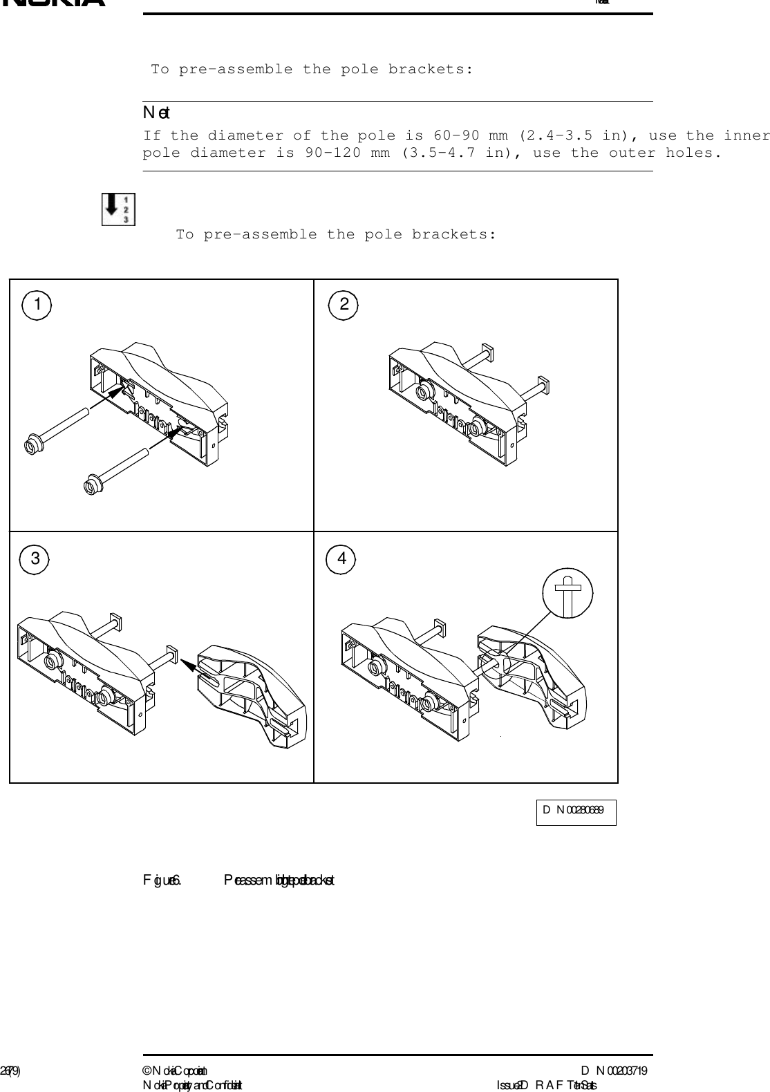
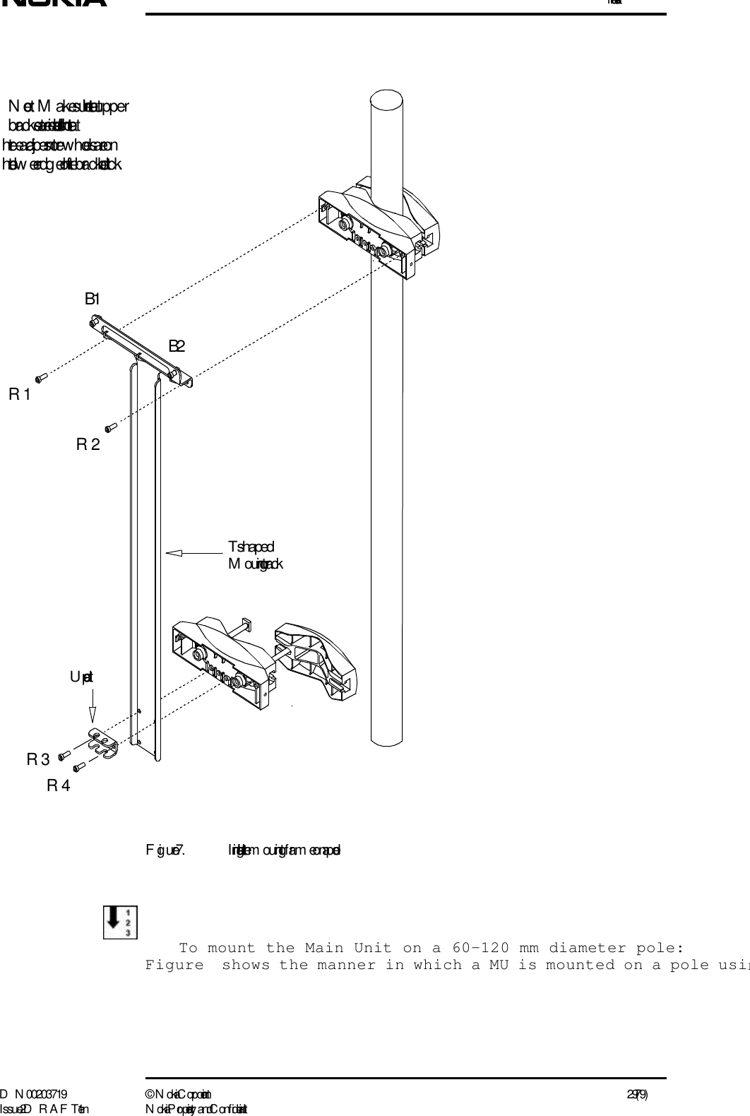
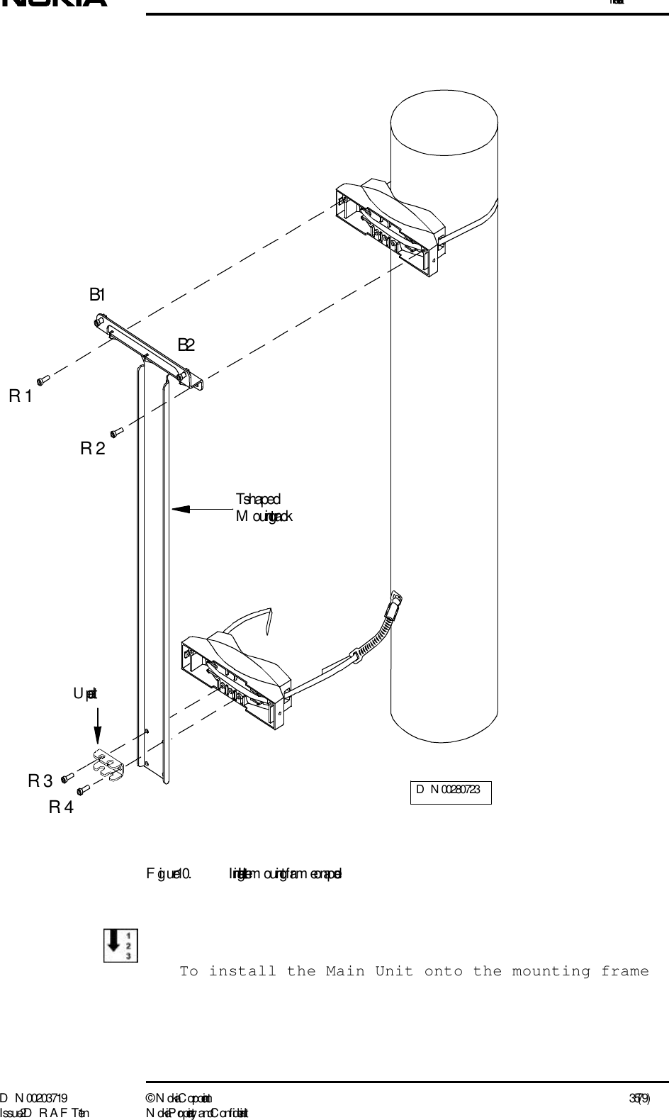
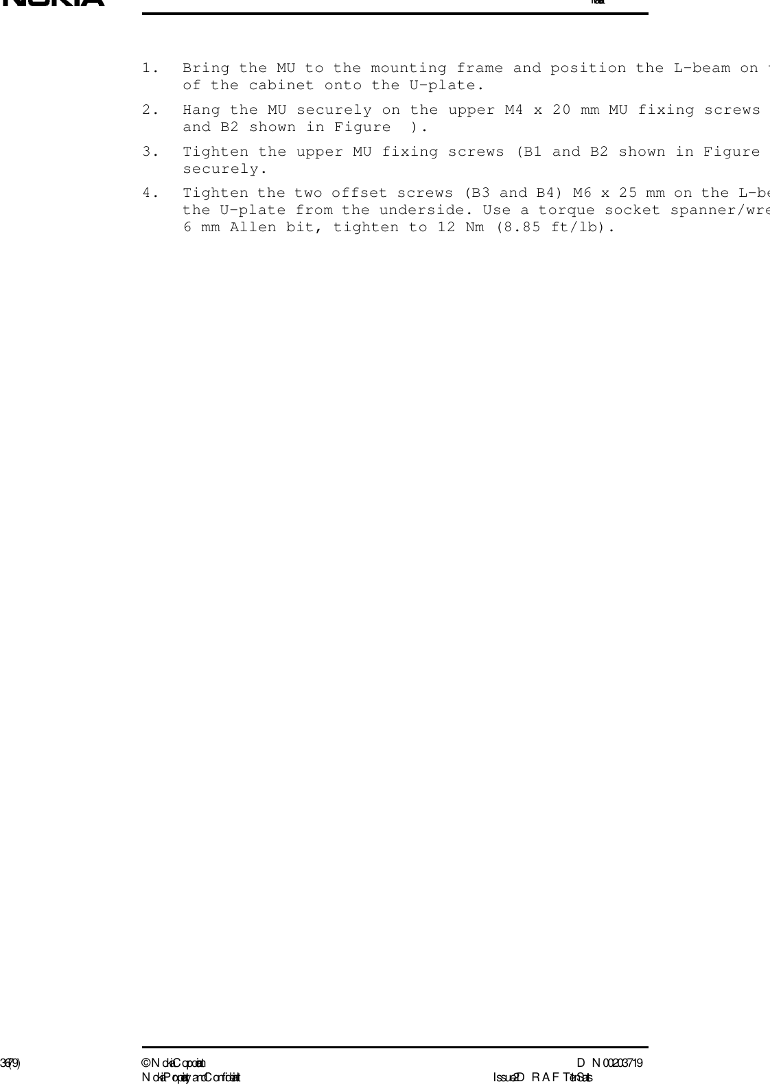
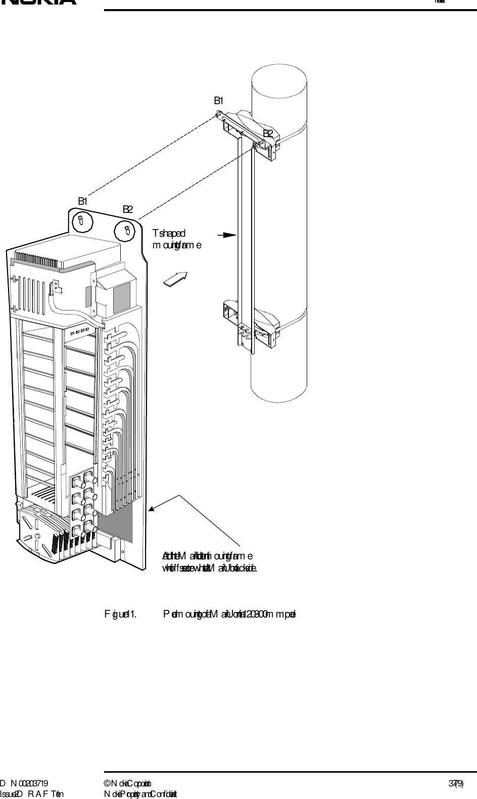
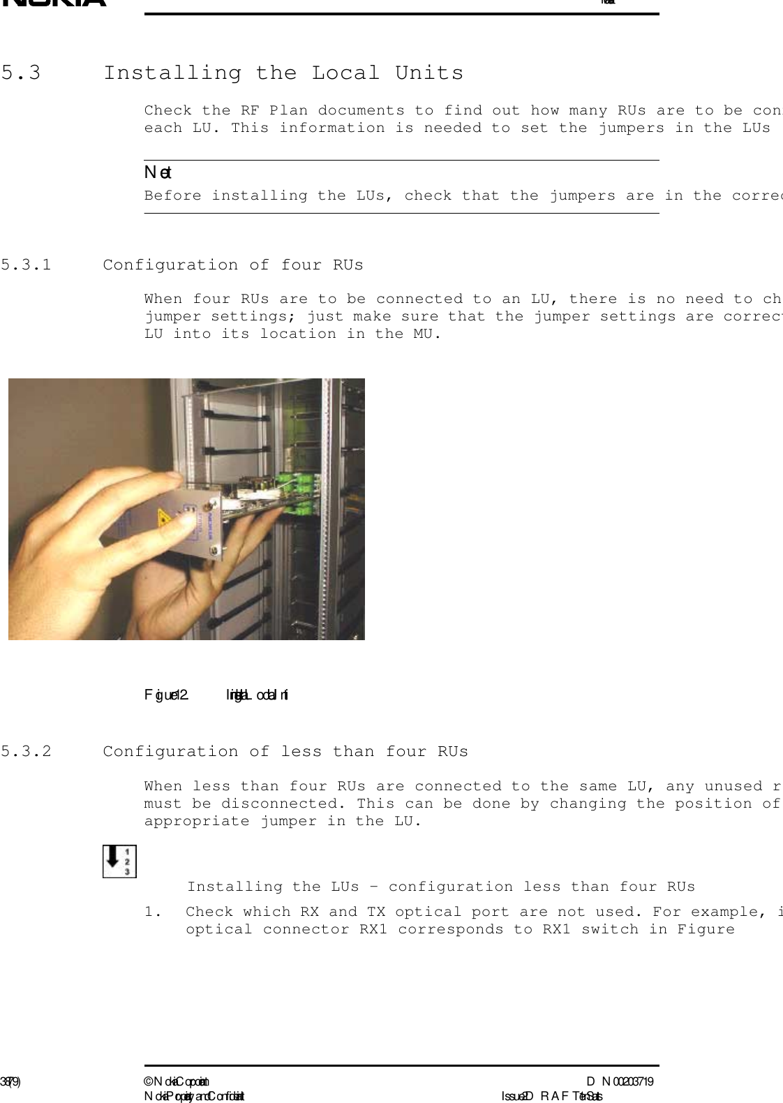
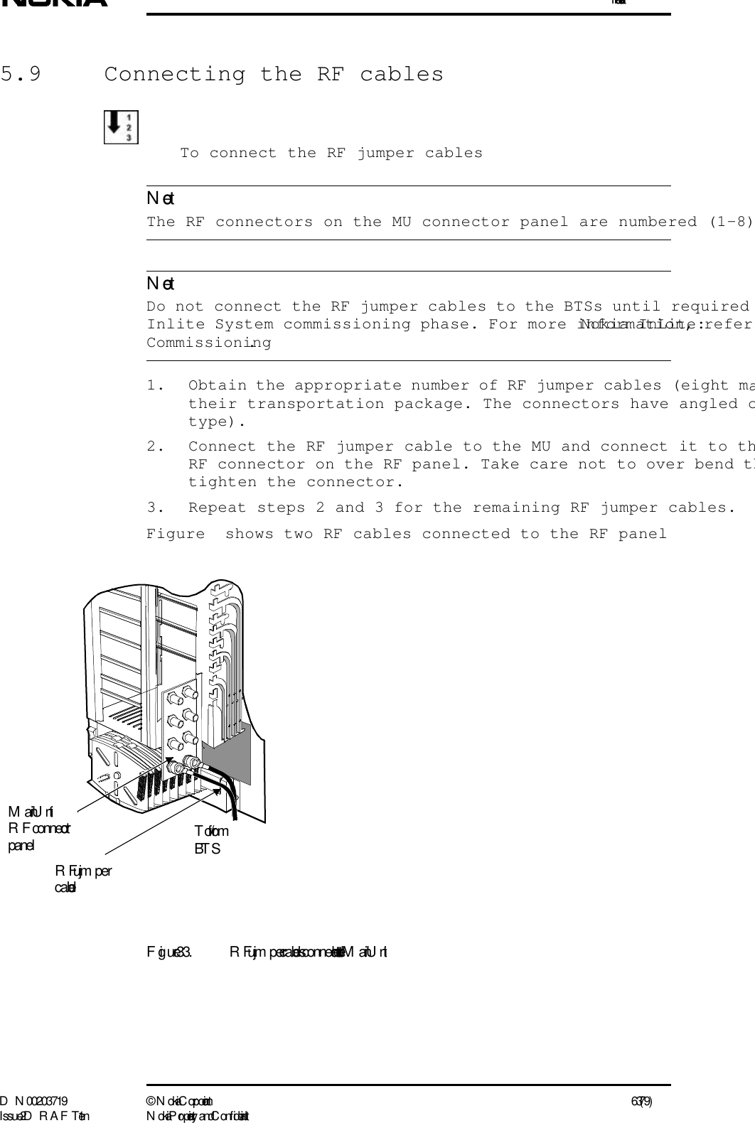
Installation
Navigation menu
Upload a User Manual
Namespaces
Wiki Guide
HTML
PDF
Info
Views
User Manual
Discussion / Help
Navigation


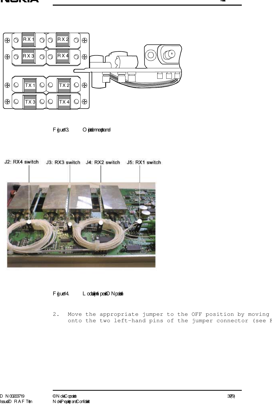
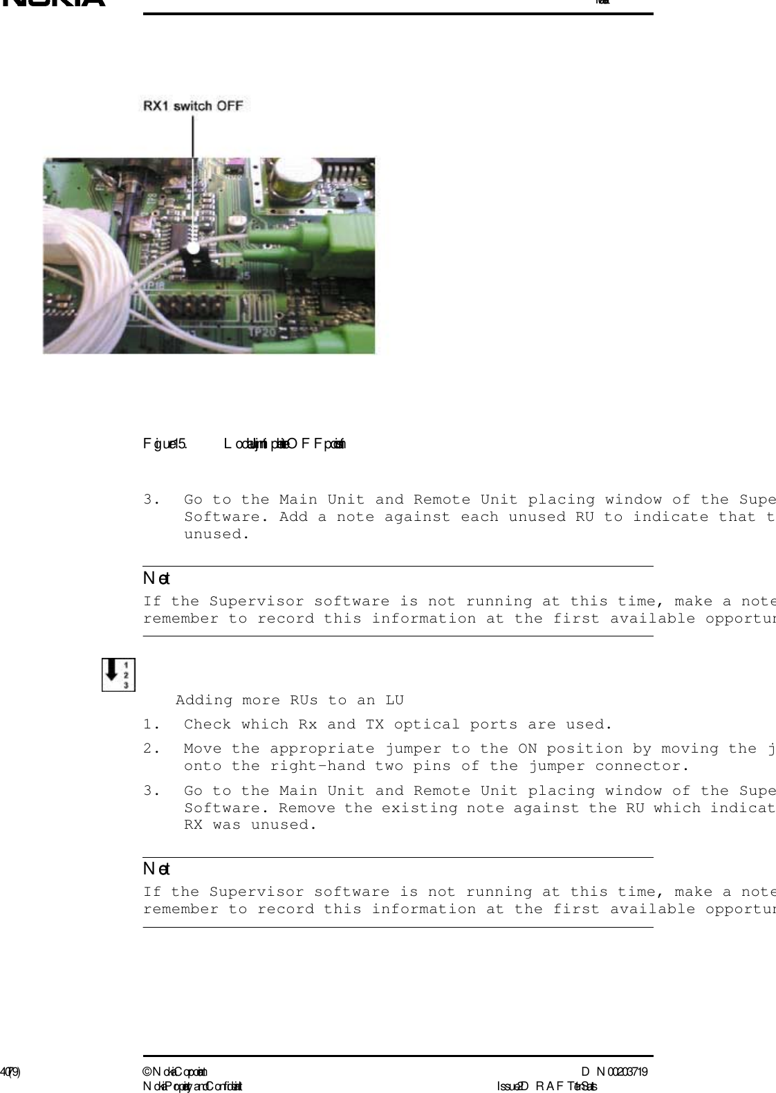
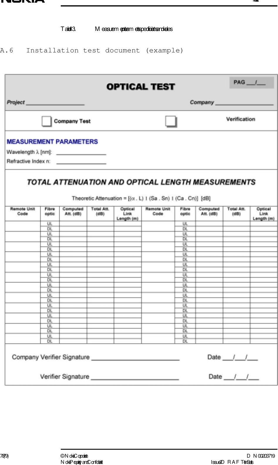
![T echnical instructions for optic fibre installation testingD N 00203719 © N okia Corporation 73 (79)I ssue 2 D RAFT 1 - en N okia Proprietary and C onf identialNoteat least, called “launching fibres”) must be connected with botso that connector attenuation is included in the measurement r The measurement must be performed as follows:1. Connect OTDR to one end of the fibre optic cable and perfomeasurement.2. Connect the OTDR to the other end of the fibre optic cable measurement.3. Average the two measurement results to obtain the real optiThe MTAV reference value is determined basing on the followingFigure 37. M TAV formulaM TAV = [ ( a x L) + (S n x Sa) + (C n x Ca) ] (dB)Where ... Represents ValueαFibre optic specific attenuation, ref erred to the reference w aveleng th (1550nm ) dB/KmL L eng th of the fibre optic under evaluation (UL+D L) KmSnN um ber of splices -SaReference splice attenuation provided in dBCnN um ber of connectors-CaReference connector attenuation dB](https://usermanual.wiki/Nokia-Solutions-and-Networks/INLITERU-01.Installation/User-Guide-174639-Page-73.png)
![T echnical instructions for optic fibre installation testingD N 00203719 © N okia Corporation 77 (79)I ssue 2 D RAFT 1 - en N okia Proprietary and C onf identialSpecification ValueRefractive index [n]1.4675W aveleng th (nm ) [l] 1550](https://usermanual.wiki/Nokia-Solutions-and-Networks/INLITERU-01.Installation/User-Guide-174639-Page-77.png)