Nokia Solutions and Networks T5EJ1 1X SC480 BTS Microcell Base Station Transmitter User Manual print instructions
Nokia Solutions and Networks 1X SC480 BTS Microcell Base Station Transmitter print instructions
Contents
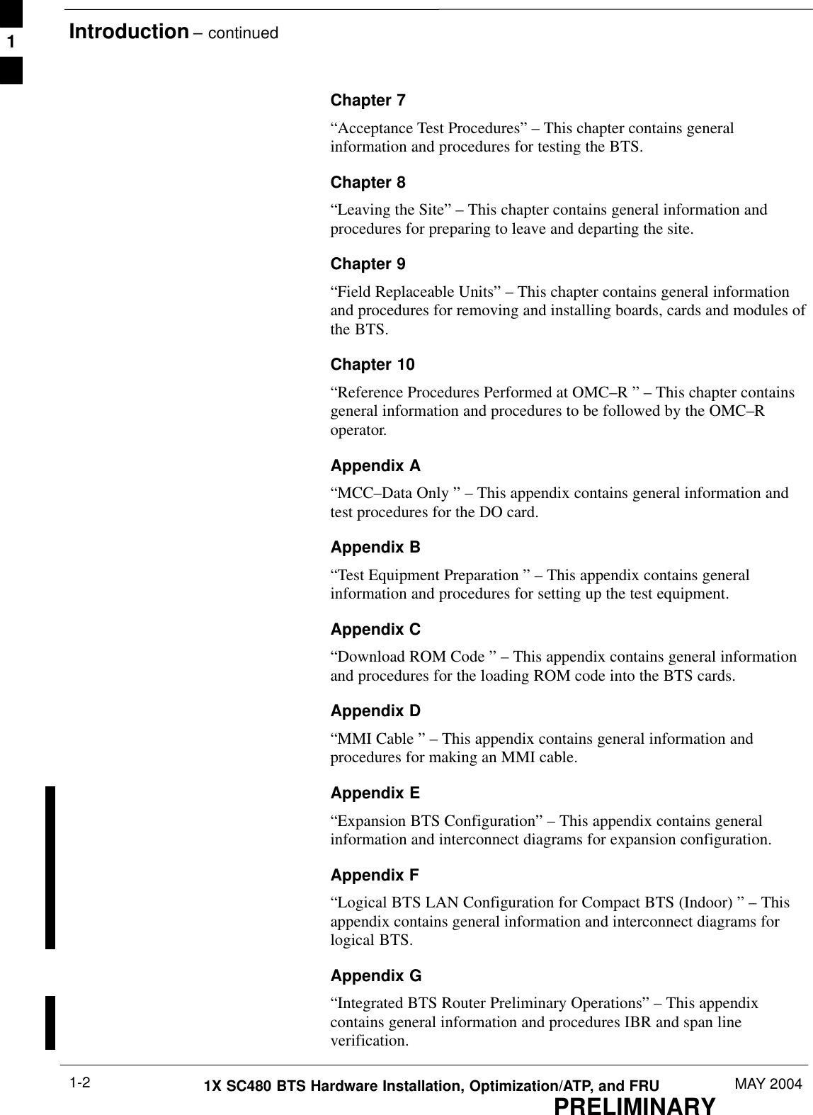
- 1. User Manual Part 1
- 2. User Manual Part 2
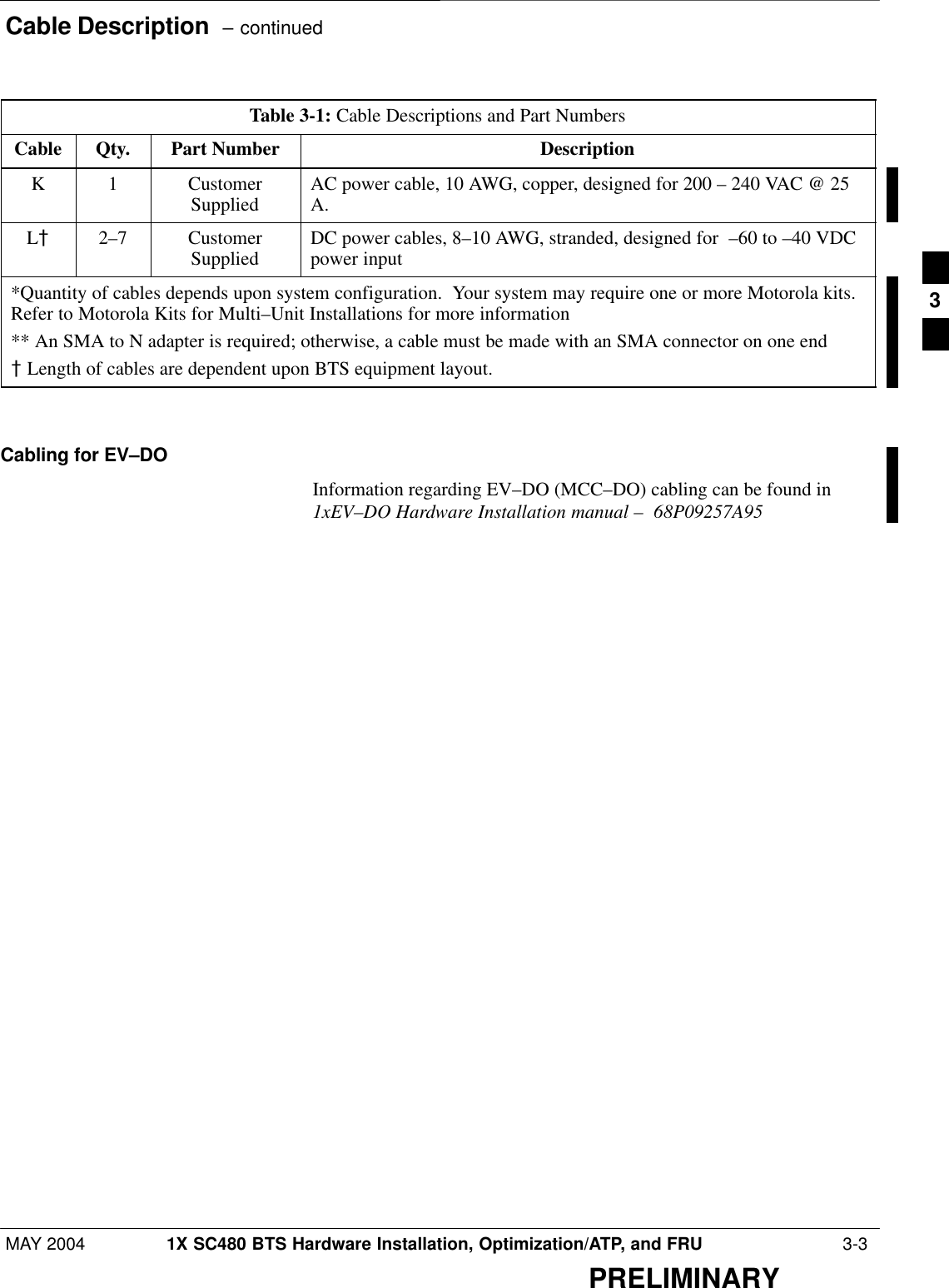
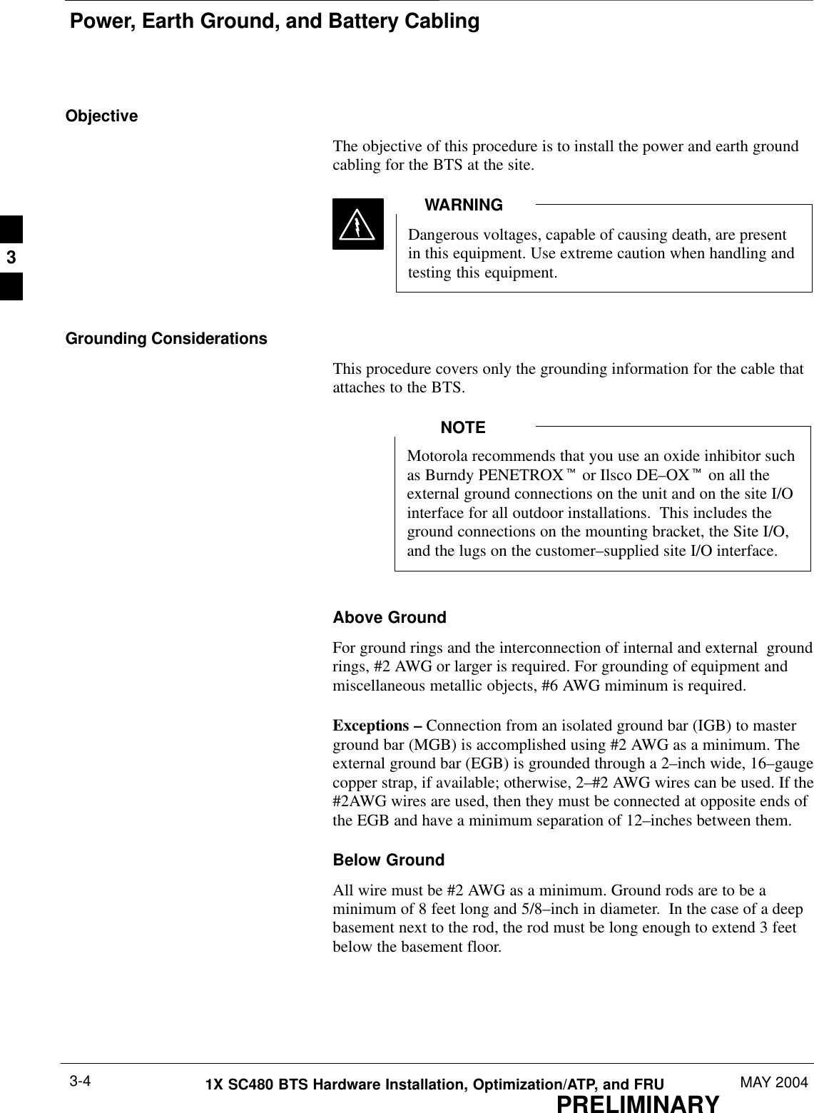
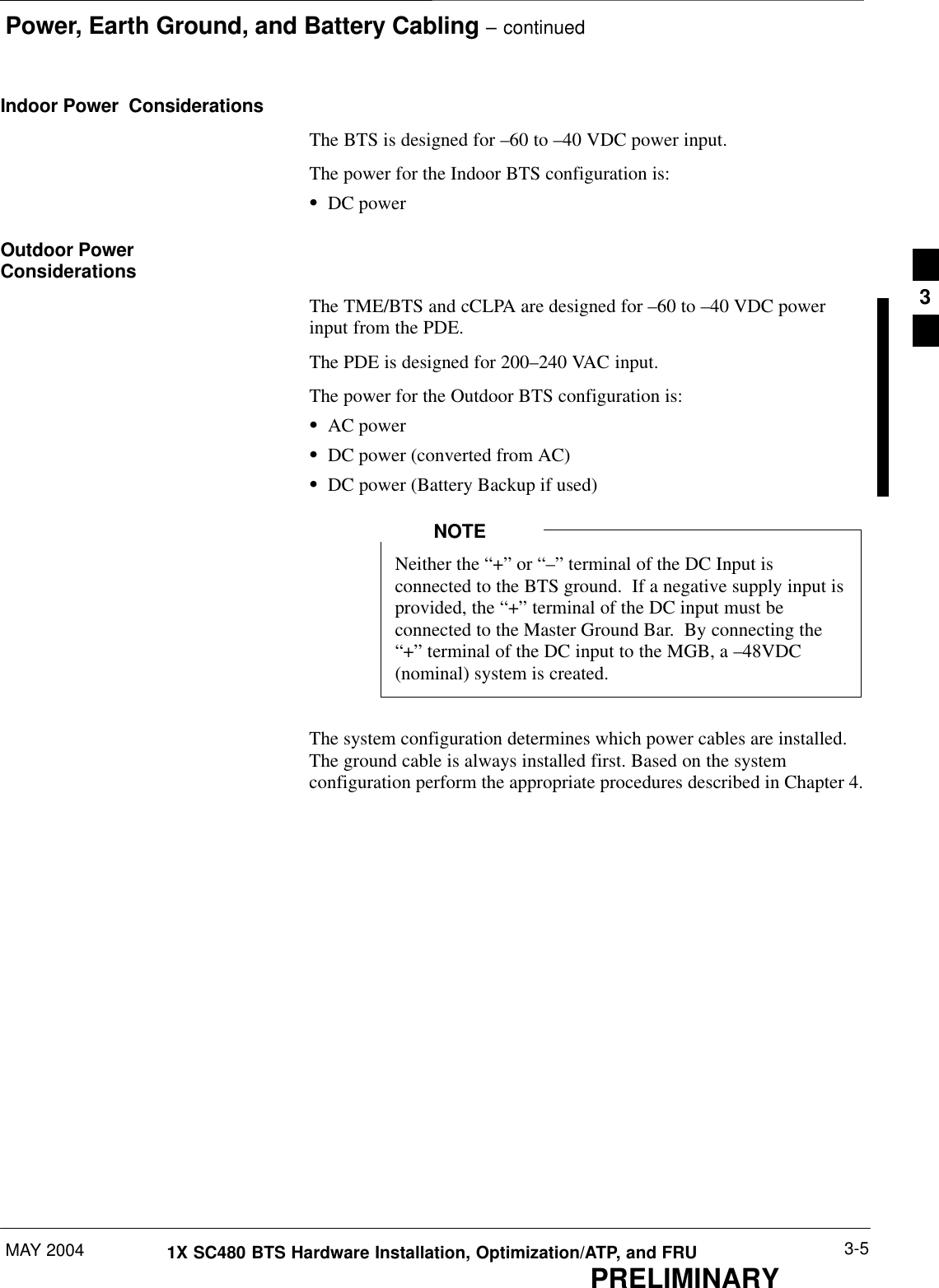
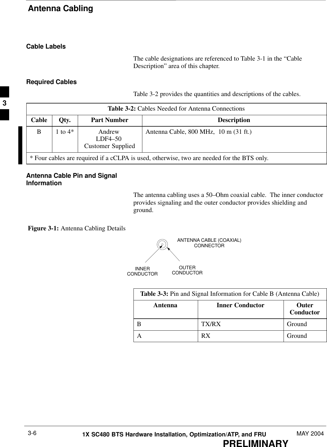
- 3. User Manual Part 3
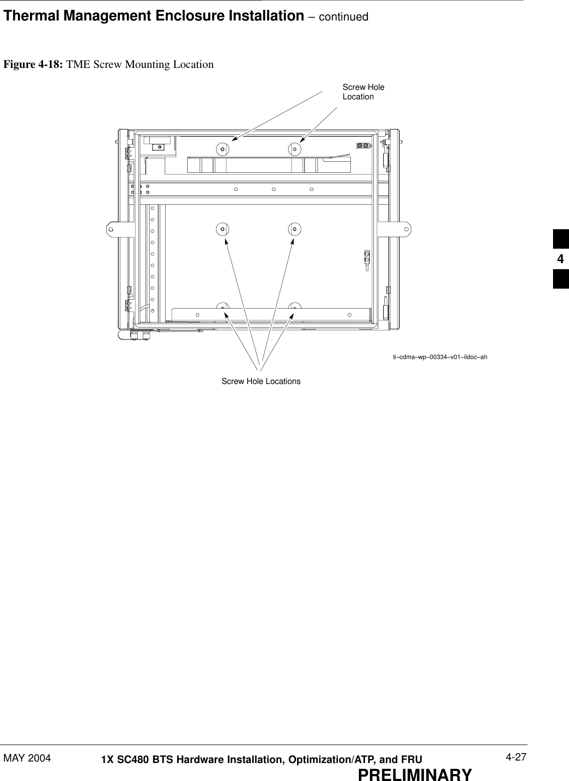
- 4. User Manual Part 4
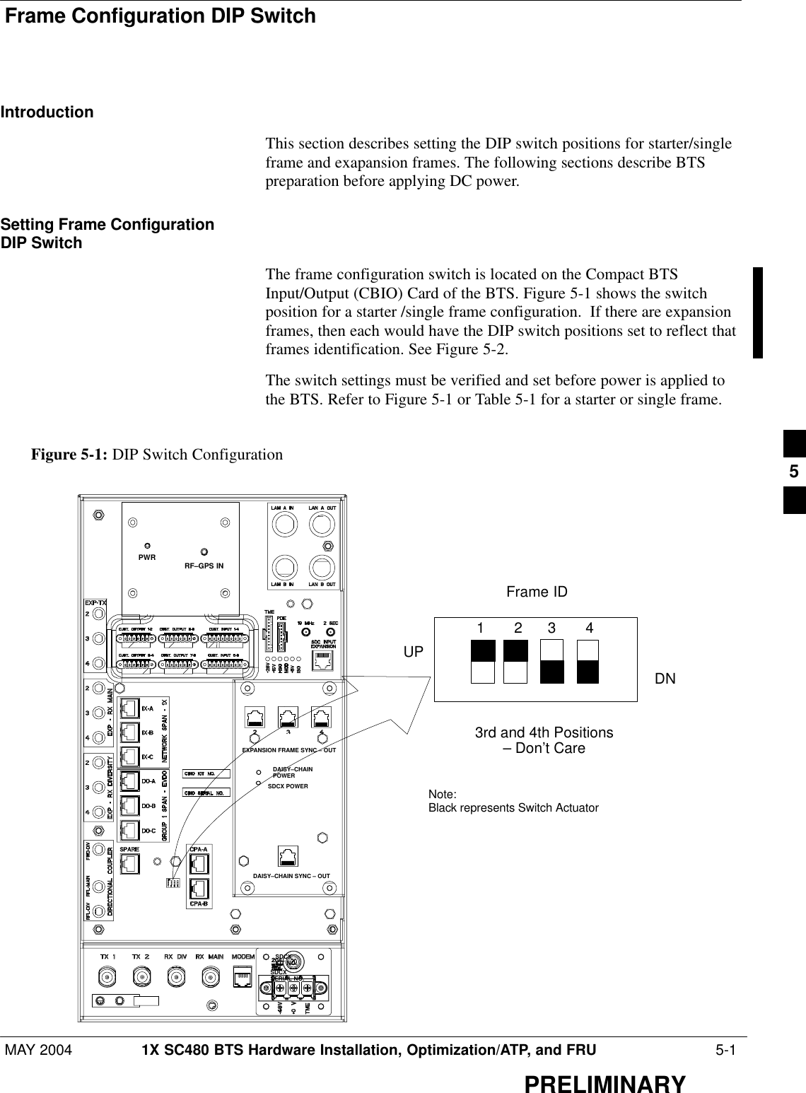
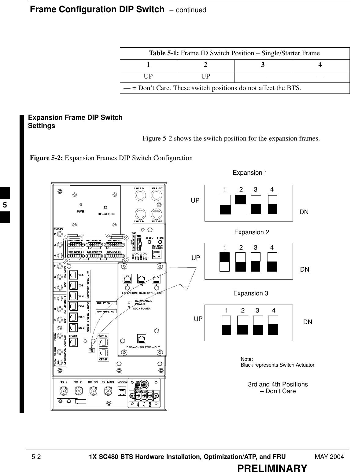
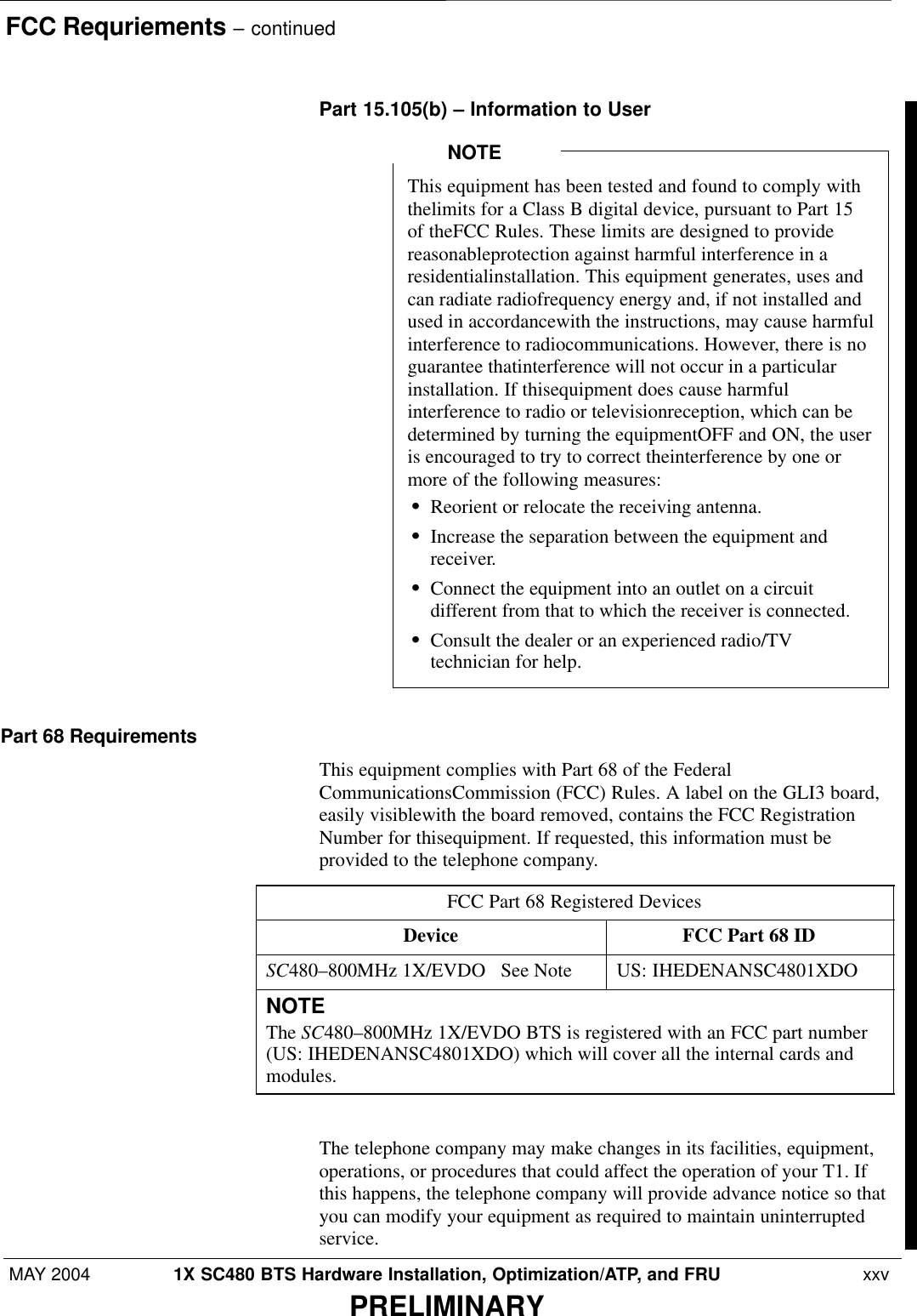
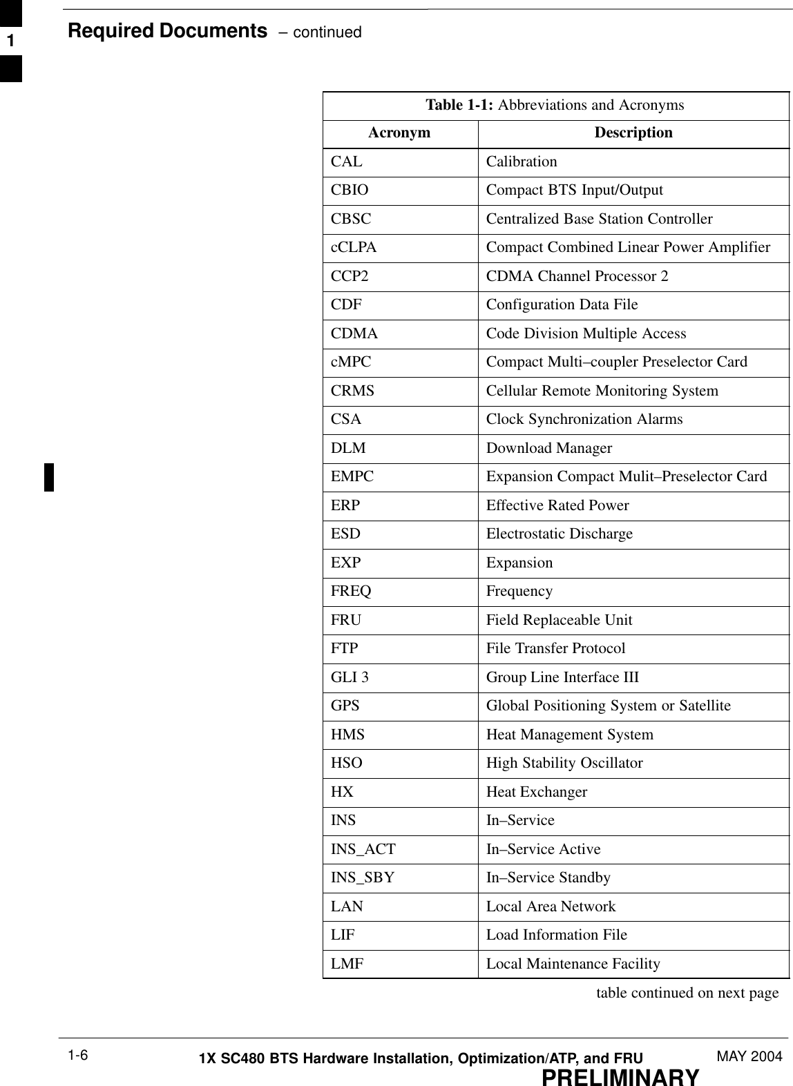
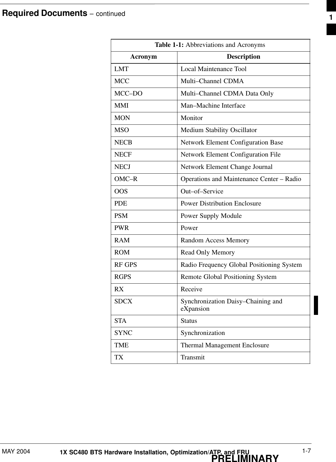
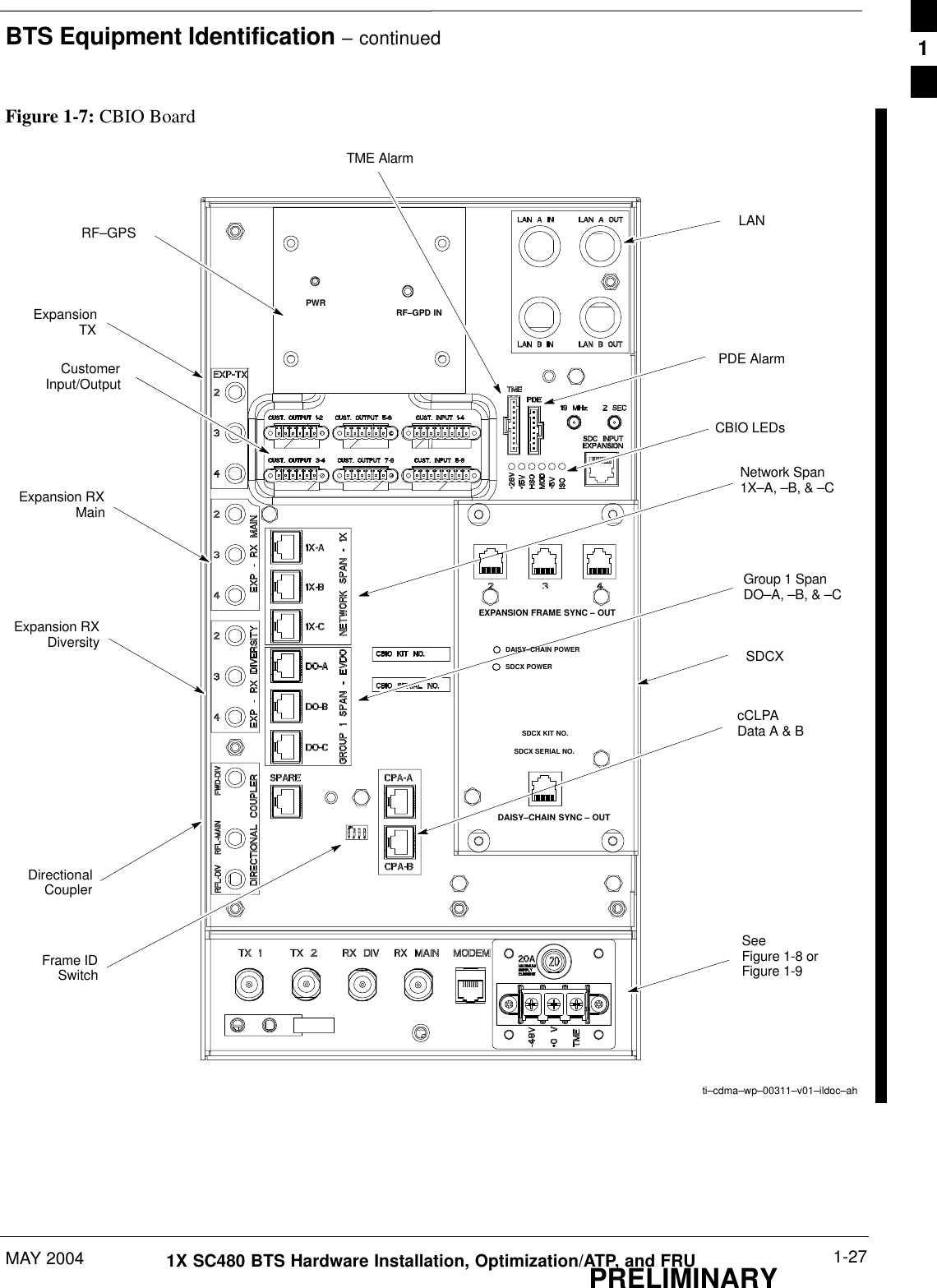
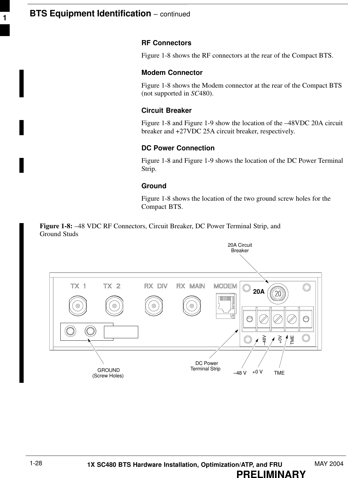
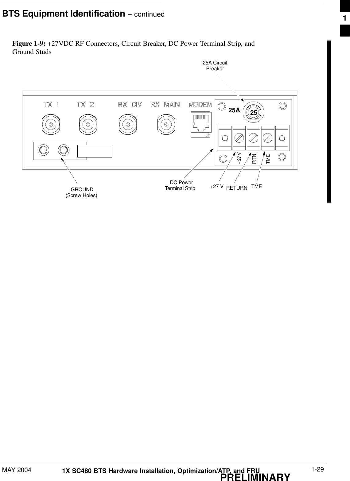
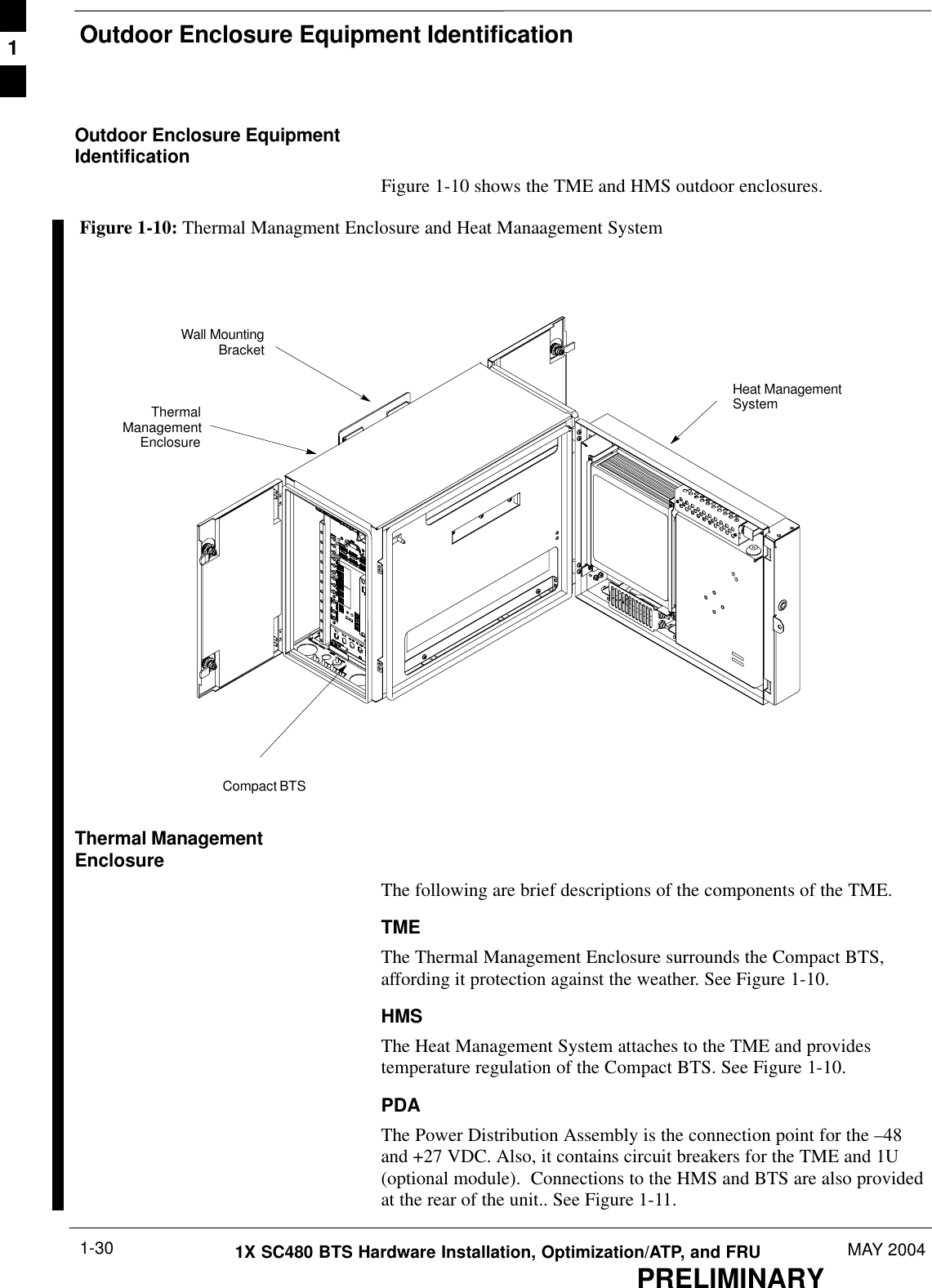
User Manual Part 1

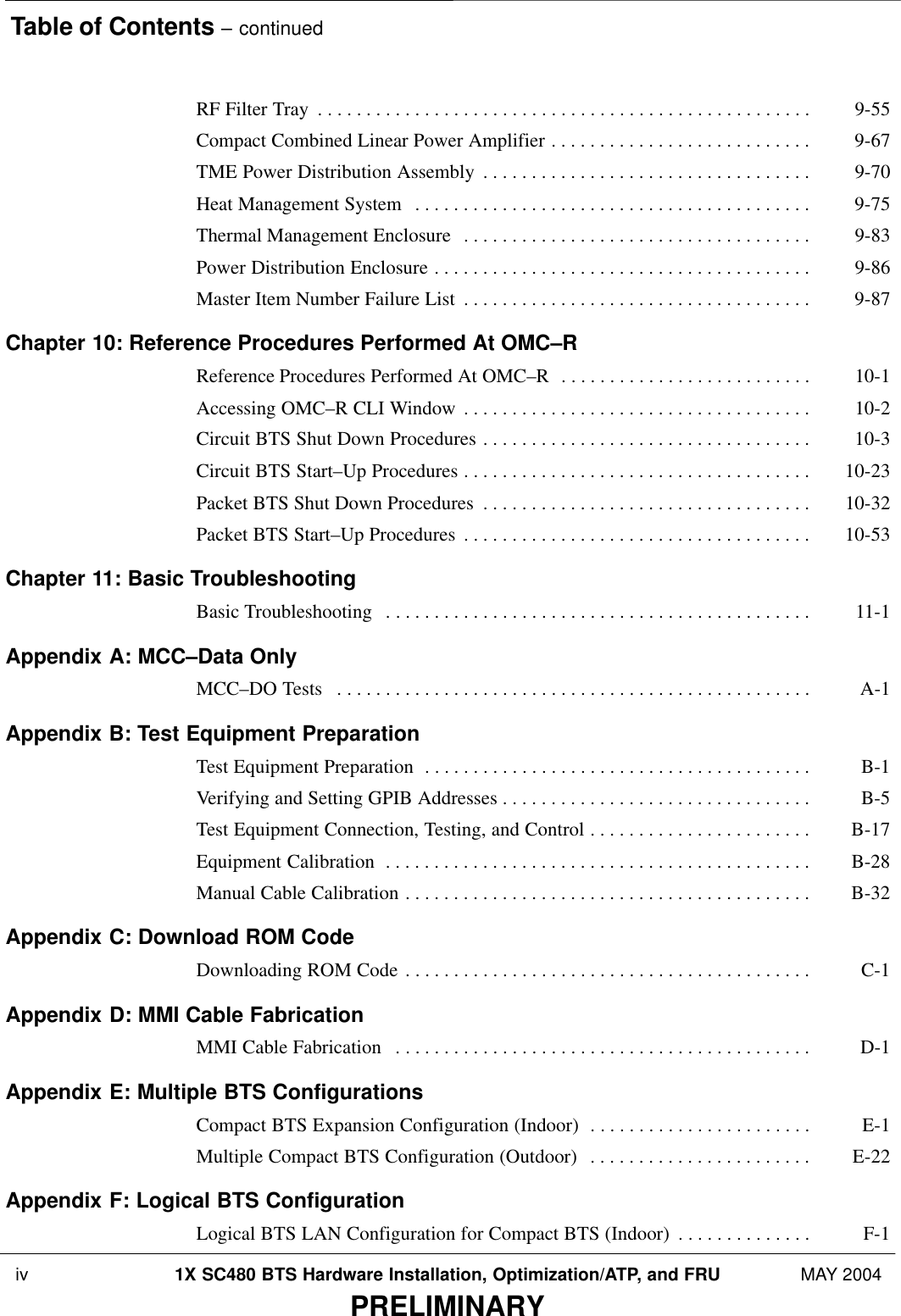
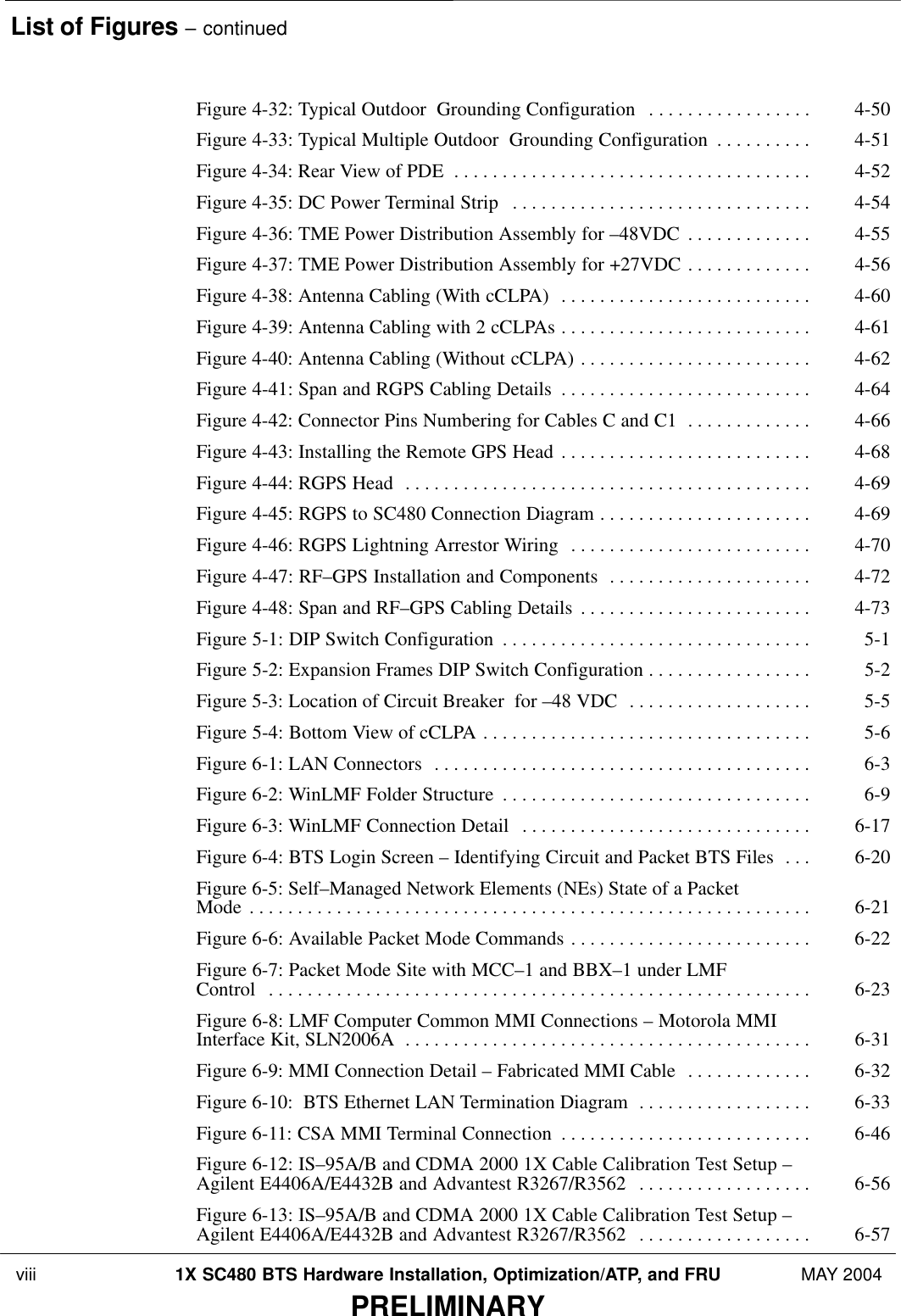
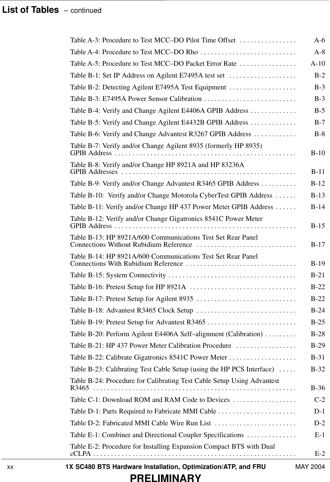
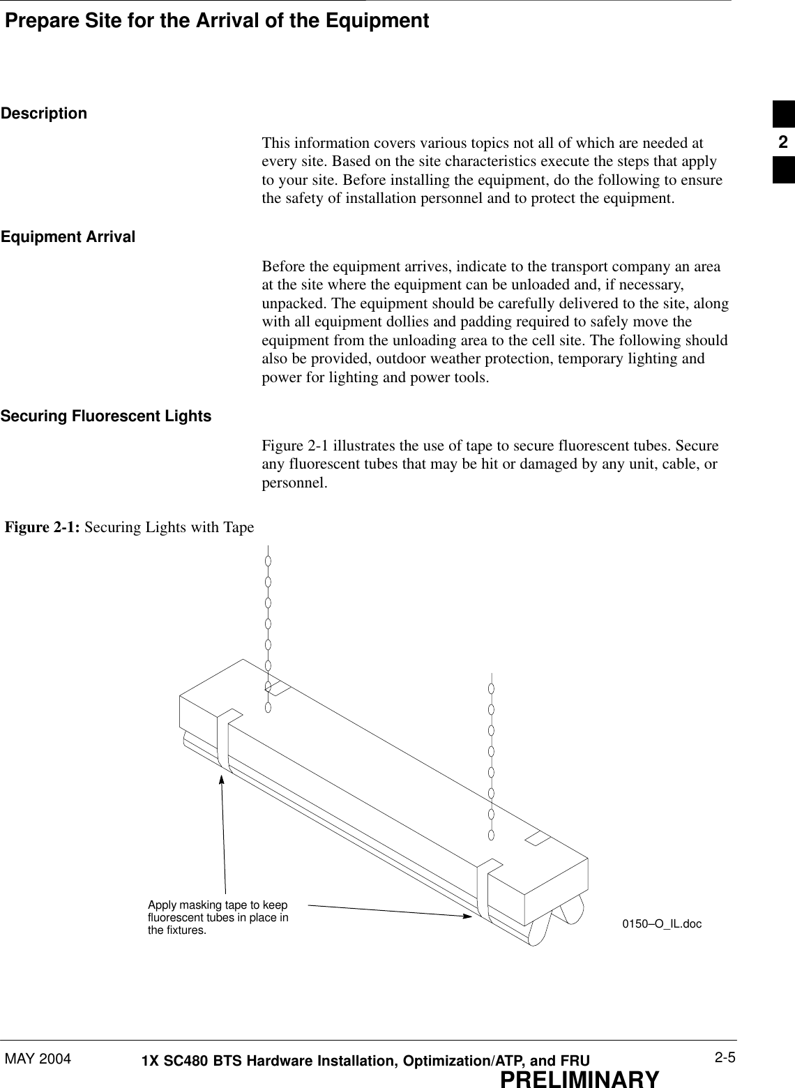
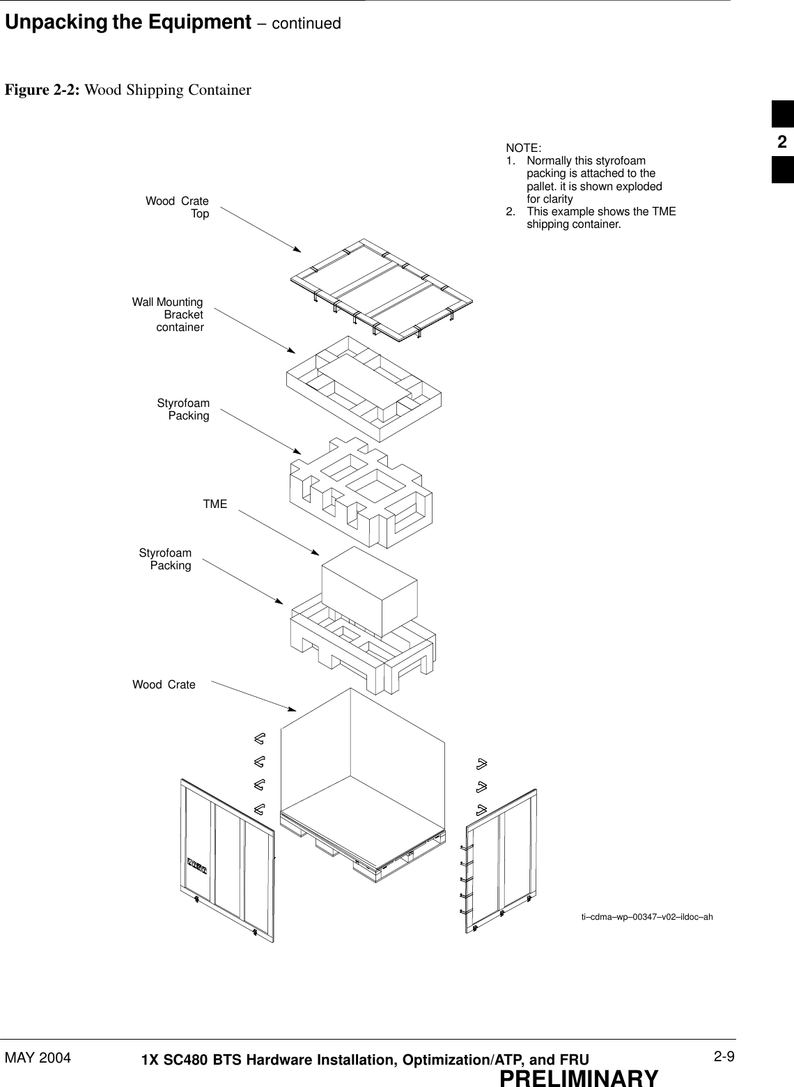
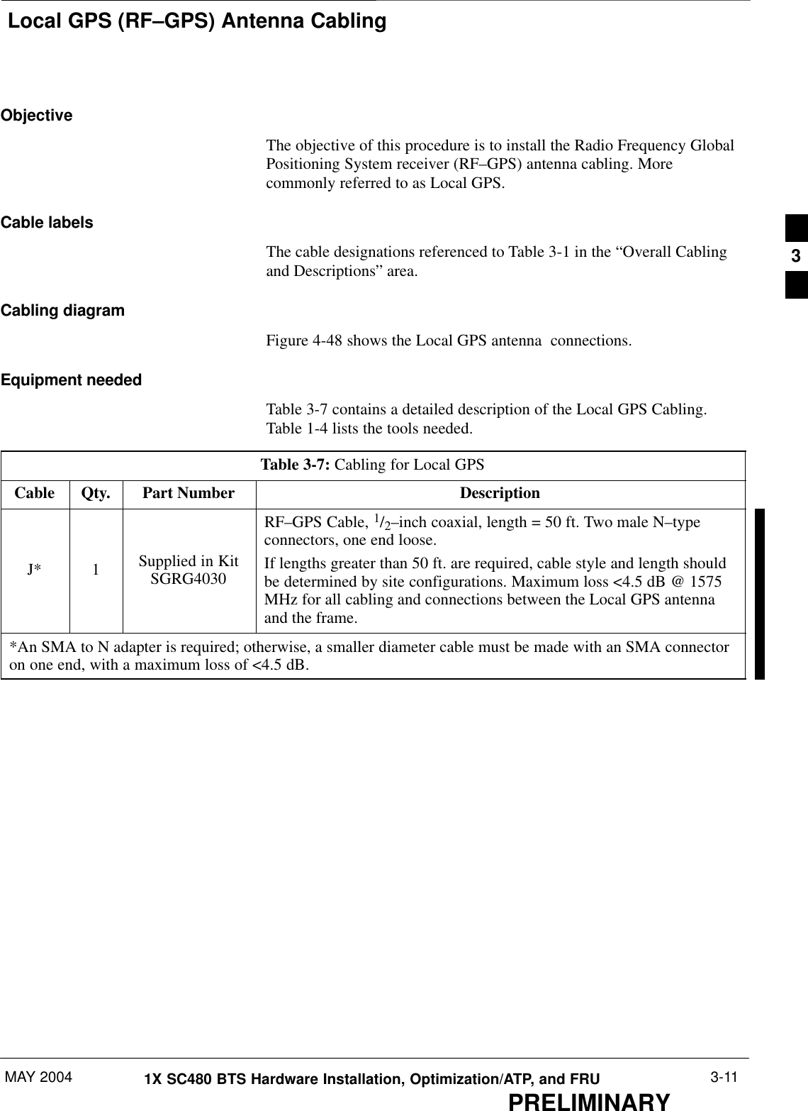
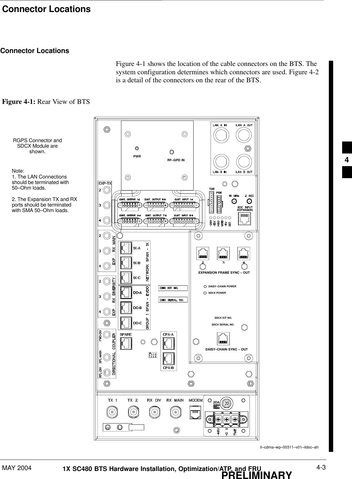
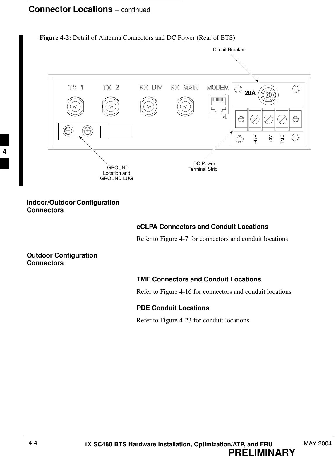
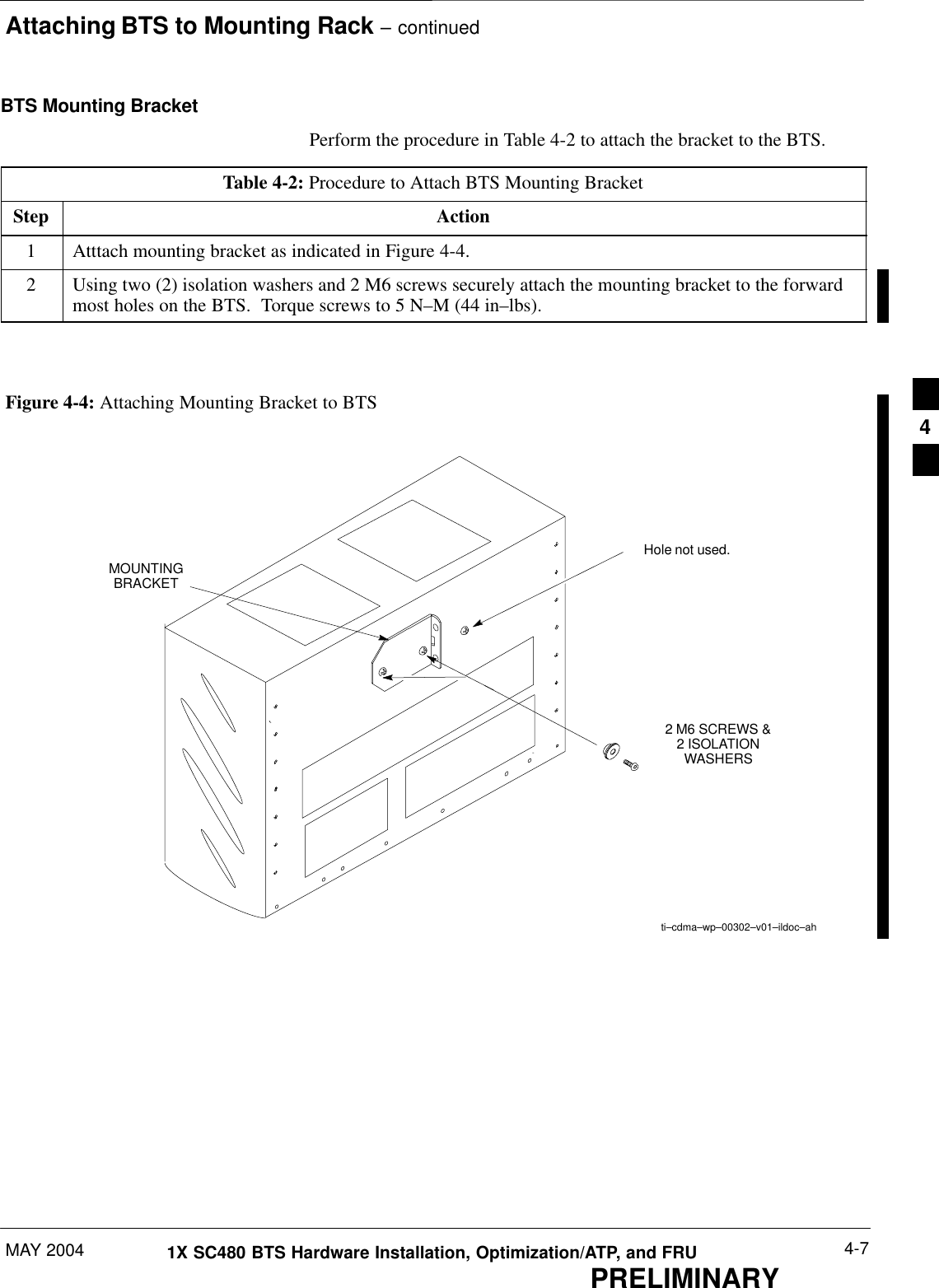
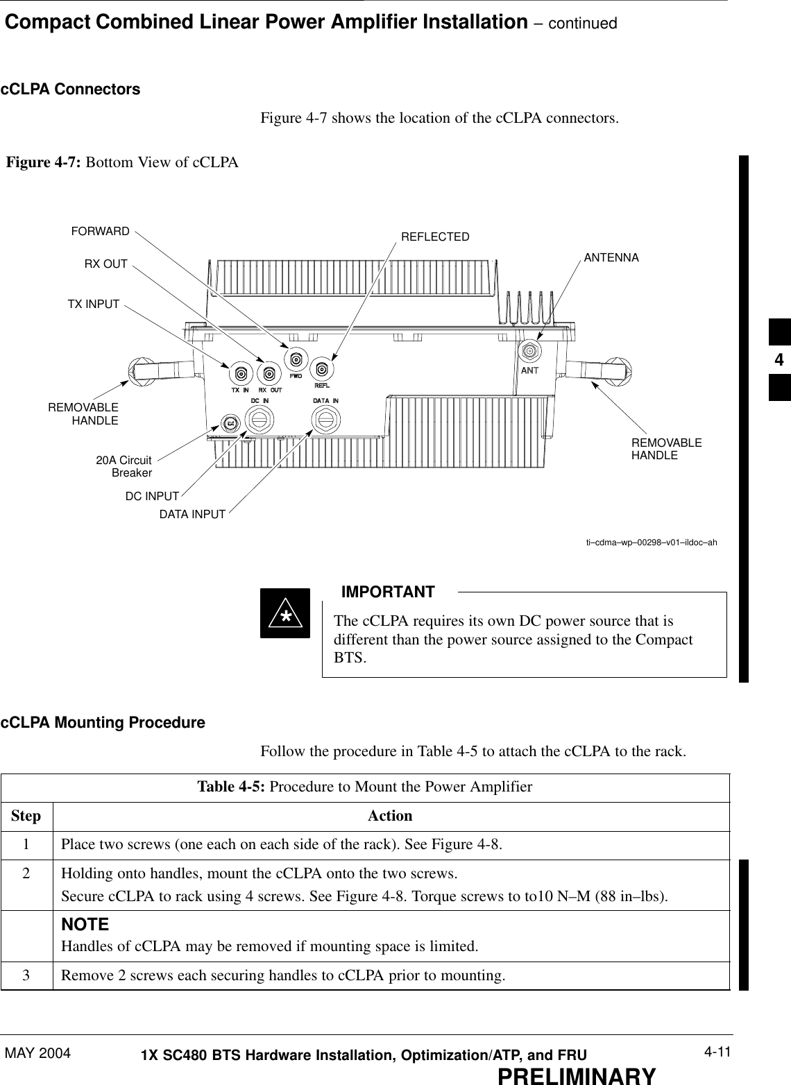
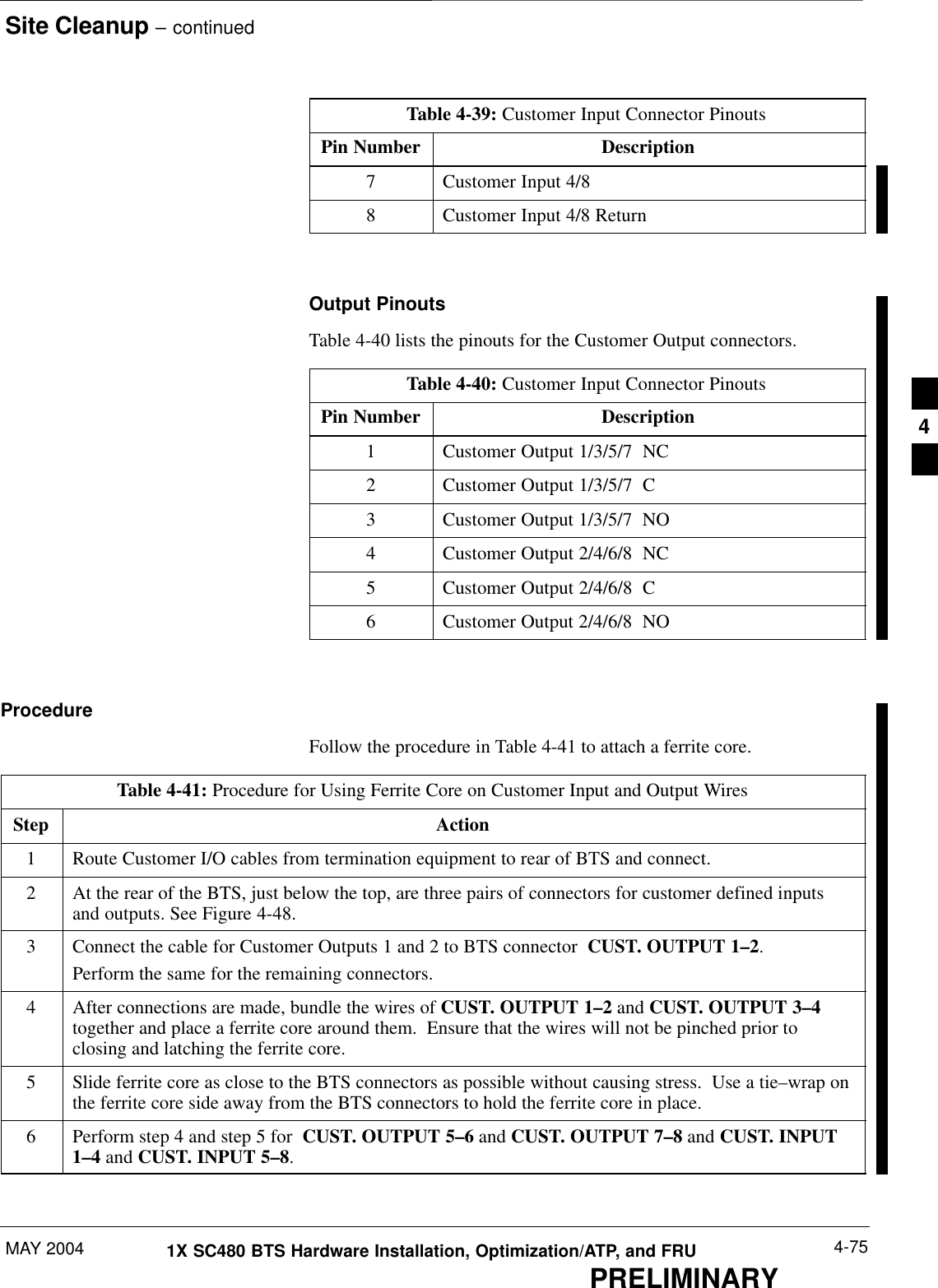
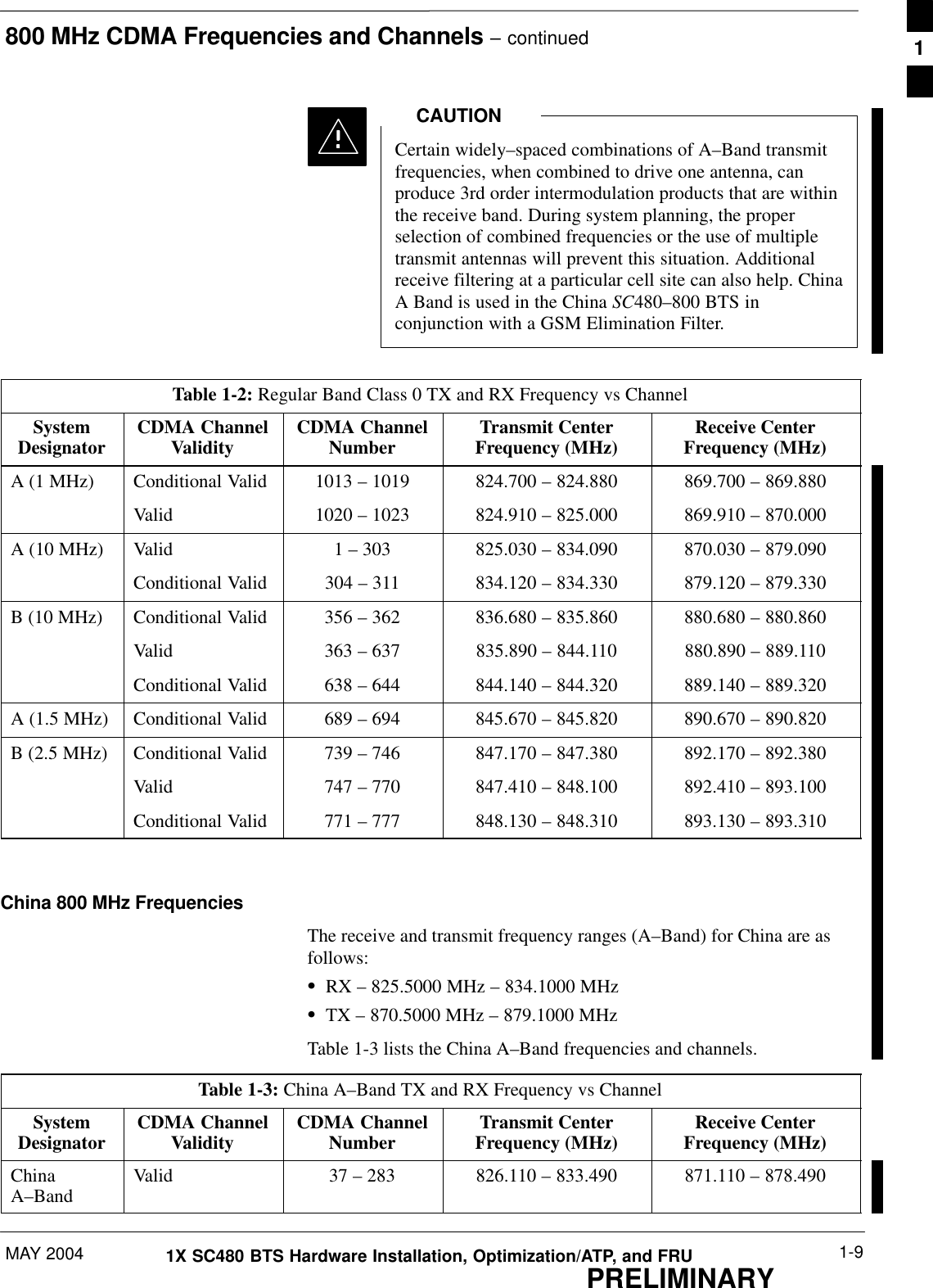
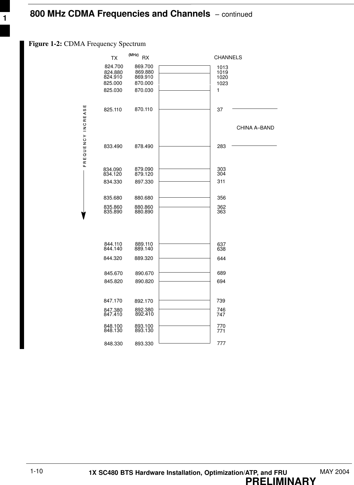
![800 MHz CDMA Frequencies and ChannelsPRELIMINARY1X SC480 BTS Hardware Installation, Optimization/ATP, and FRU MAY 20041-8800 MHz Center FrequenciesTable 1-2 lists the selected 800 MHz CDMA candidate operatingchannels and the corresponding transmit and receive frequencies forRegular Band Class 0 (North America). Figure 1-2 shows the CDMAFrequency Spectrum for Table 1-2. Center frequencies (in MHz) forchannels not shown in the table may be calculated as follows:For Channels 1 – 799SFor TXTX = 870 + (0.03 * Channel #)Example: Channel 262TX = 870 +0.03 * 262 TX = 877.86 MHzSFor RXRX = 825 + (0.03 * Channel#)Example: Channel 262RX = 825 + (0.03 * 262)RX = 832.860 MHzFor Channels 991 – 1023SFor TXTX = 870 + [0.03 *(Channel# – 1023)]Example: Channel 1015TX = 870 + [0.03 * (1015 – 1023)]TX = 870.240 MHzSFor RXRX = 825 + [0.03 * (Channel# – 1023)]Example: Channel 262RX = 825 + [0.03 * (262–1023)]RX = 847.830 MHzConditionally Valid – Valid channels in TIA/EIA–97–Dthat are <885 kHz from the operator’s band edge. If theoperator’s system must coexist with another system thatuses an adjacent frequency band, it is recommended thatthe operator coordinate with the other operator todetermine if the usage of the Reduced–Sideband SpectralMask is required for Conditionally Valid channels. TheReduced–Sideband Spectral Mask is in addition to otherspectral masks that apply.NOTE1](https://usermanual.wiki/Nokia-Solutions-and-Networks/T5EJ1.User-Manual-Part-1/User-Guide-430567-Page-42.png)
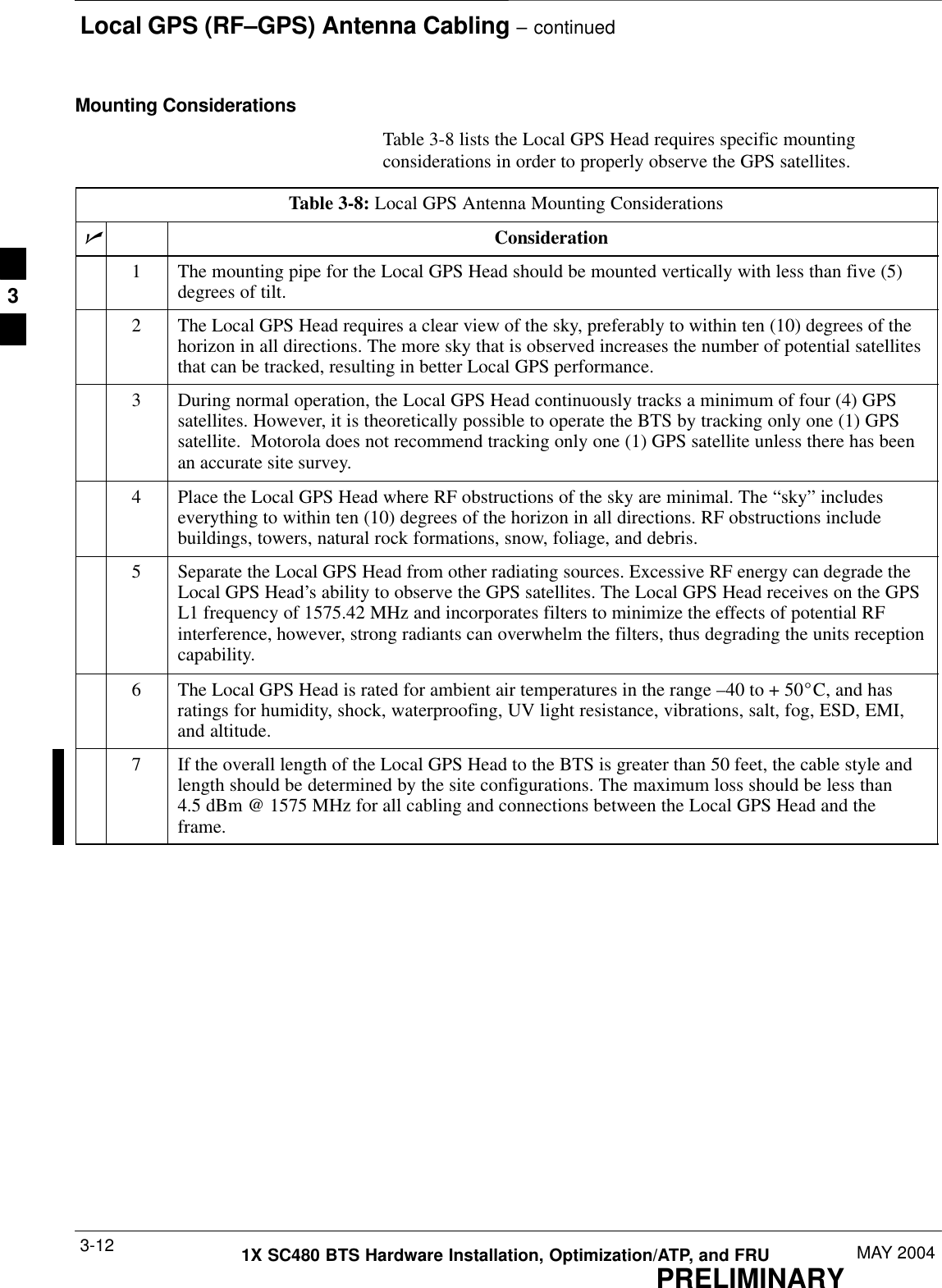
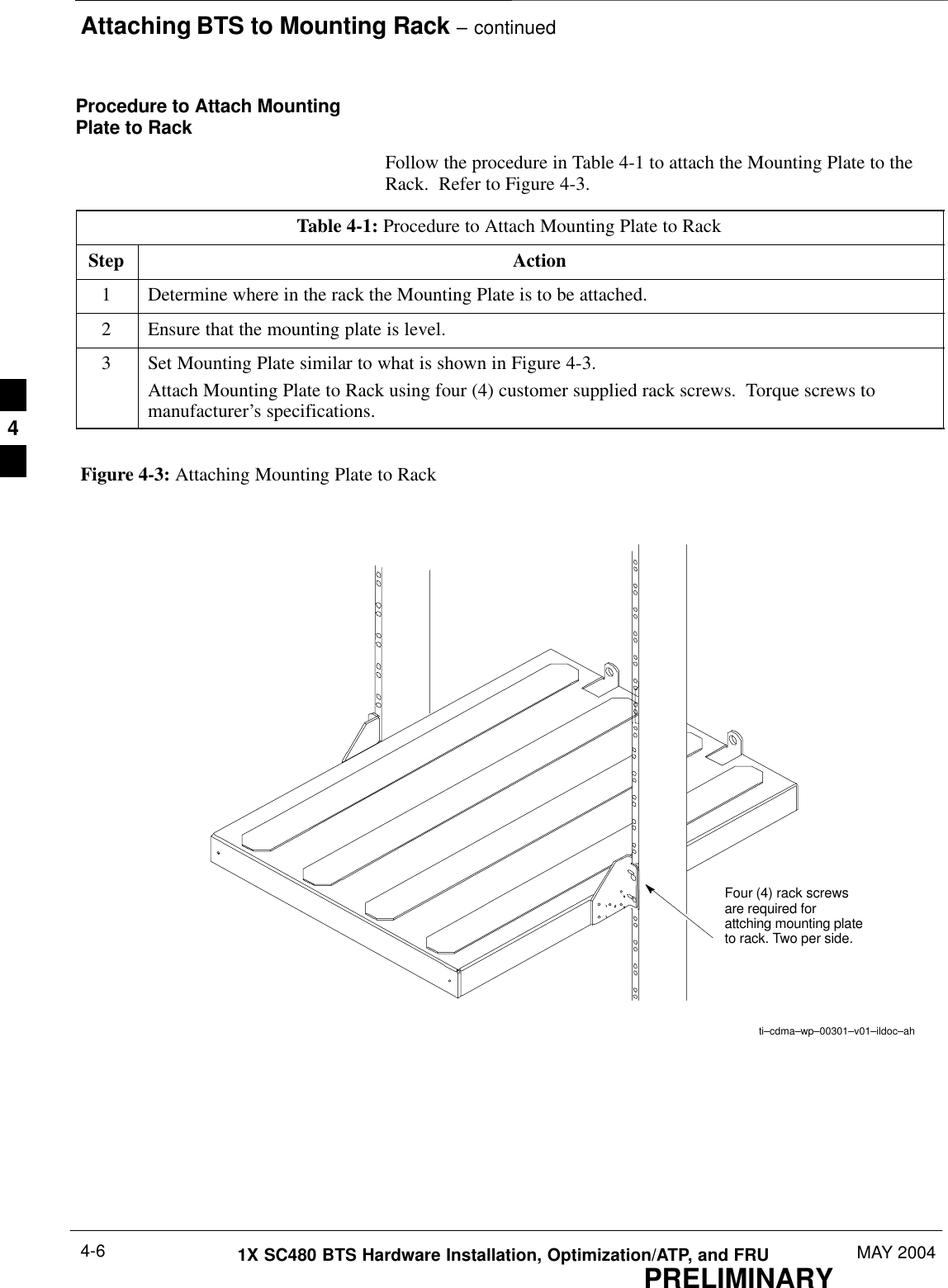
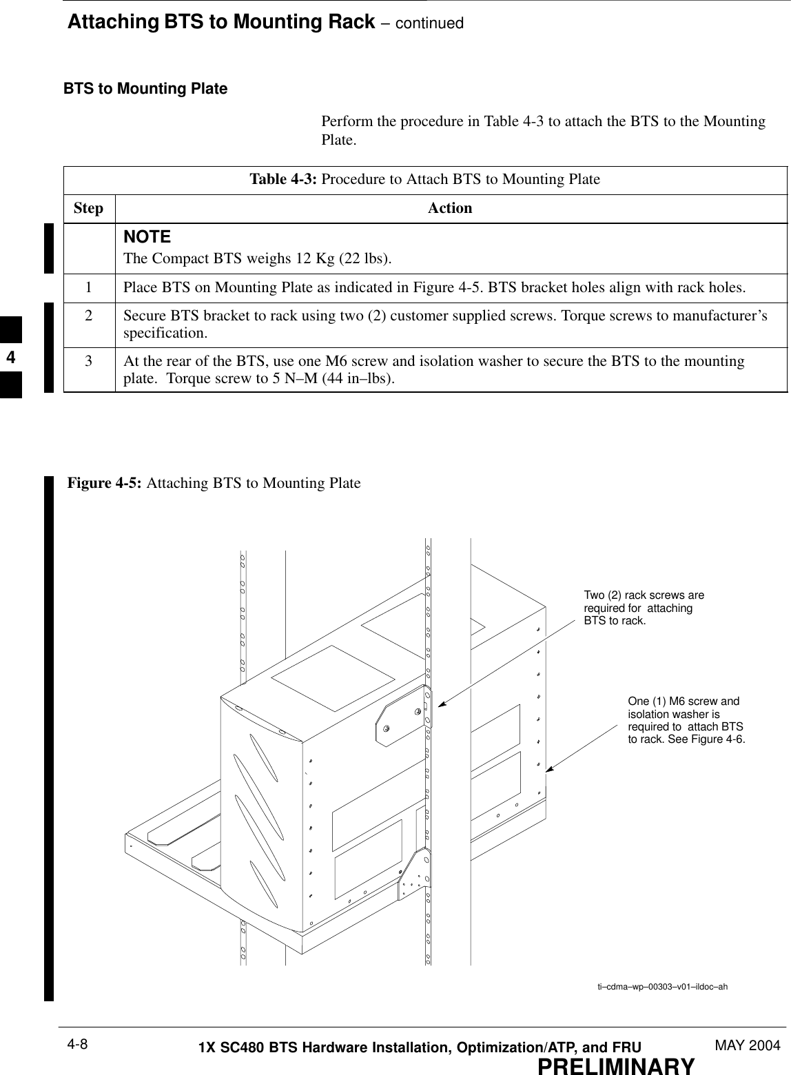
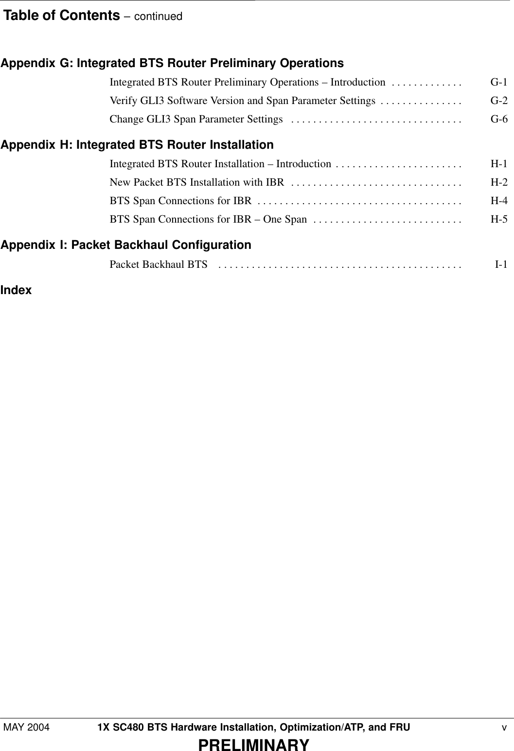
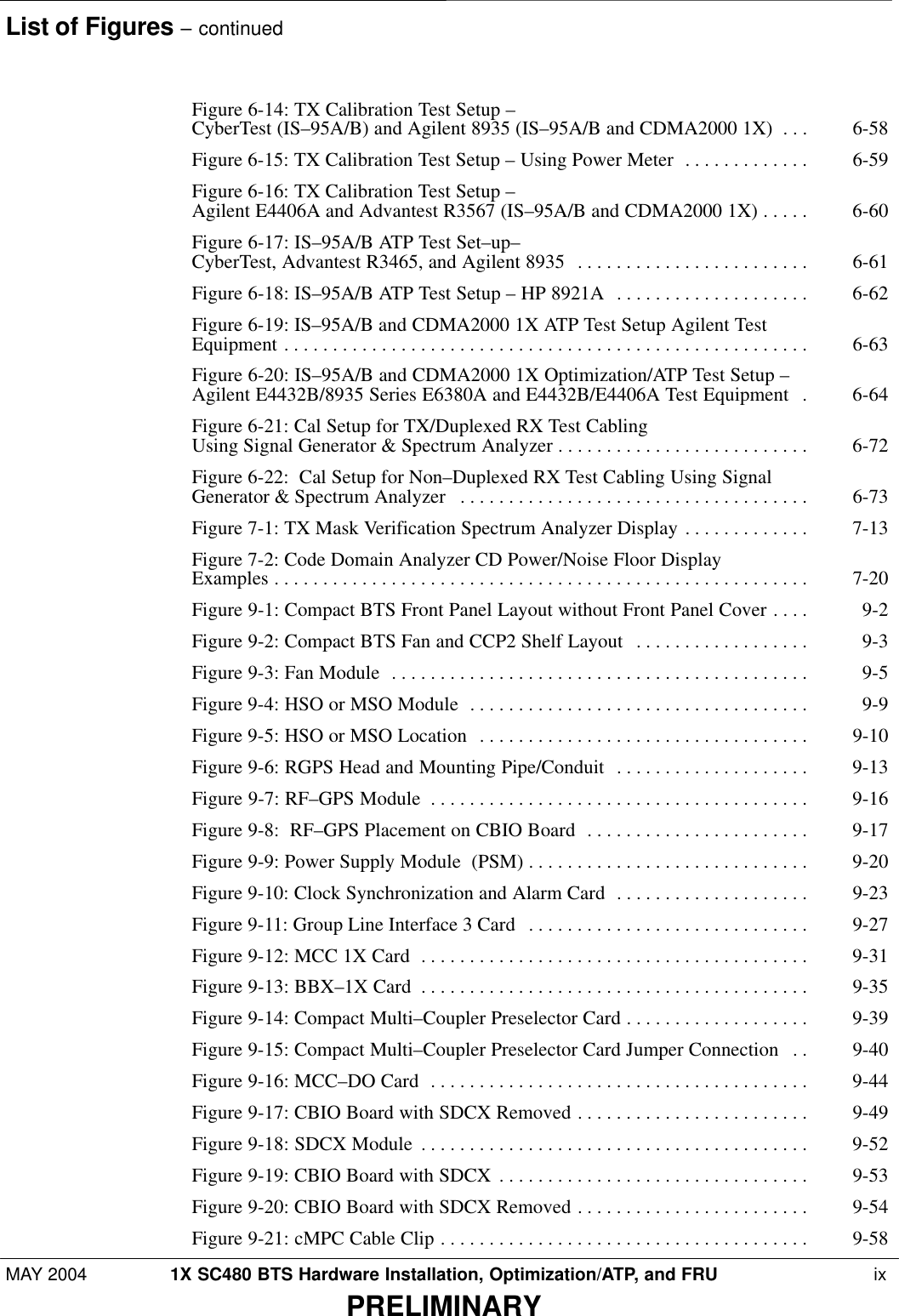
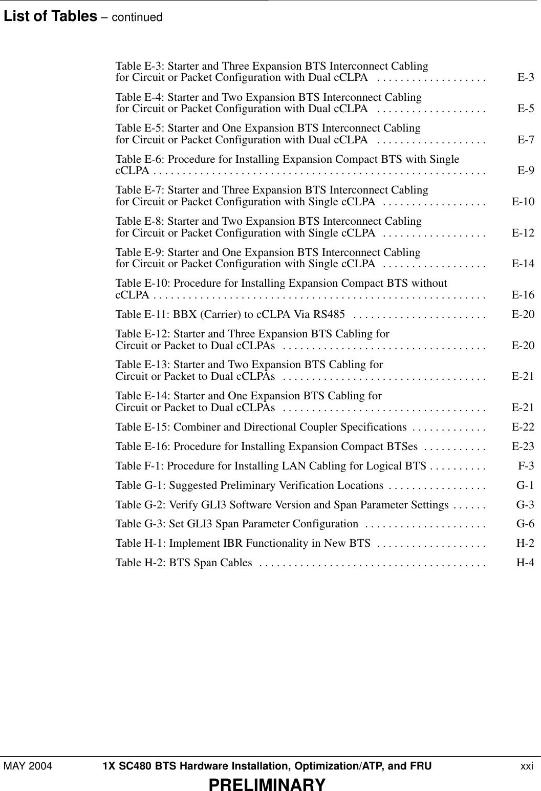
![Site Inspections – continuedPRELIMINARY1X SC480 BTS Hardware Installation, Optimization/ATP, and FRU MAY 20042-4Grounding InspectionsIndoor installationsFor indoor installations refer to the Grounding Guideline for CellularRadio Installations (68P81150E62) for all grounding inspectionprocedures.Verify the following:SAll ground cables have a bend radius of 20 cm (8 inches) or more.SMetallic lines (span, phone[modem], RGPS, power and antenna) thatenter or leave the site should be equipped with a 3-electrode gas tubeprotector. The ground side of the gas tubes should be tied to theMaster Ground Bus (MGB).SAll installed cable racks (in the same ground zone) are jumperedtogether.Cable racks in an Isolated Ground Zone (IGZ) are not to beconnected to a cable rack in a non-IGZ. For moreinformation on IGZ, see Grounding Guideline for CellularRadio Installations, Motorola part number 68P81150E62or Appendix C of Standards and Guidelines forCommunications Sites (Motorola part number9882904Y01)WARNINGOutdoor InstallationsFor outdoor installations refer to the Grounding Guideline for CellularRadio Installations (Motorola part number 68P81150E62) or AppendixC of Standards and Guidelines for Communications Sites (Motorola partnumber 9882904Y01) for all grounding inspection procedures.Verify the following:SAll outdoor enclosures are grounded to system masrter ground.SAll enclosures have conduit attached.SIt is recommended that all metallic lines (span, RGPS, power, andantenna) that enter or leave the site are be equipped with a surgesuppression device (lightning arrestor).2](https://usermanual.wiki/Nokia-Solutions-and-Networks/T5EJ1.User-Manual-Part-1/User-Guide-430567-Page-74.png)