Nokia Solutions and Networks T5EJ1 1X SC480 BTS Microcell Base Station Transmitter User Manual print instructions
Nokia Solutions and Networks 1X SC480 BTS Microcell Base Station Transmitter print instructions
Contents
- 1. User Manual Part 1
- 2. User Manual Part 2
- 3. User Manual Part 3
- 4. User Manual Part 4
User Manual Part 3
High and Medium Stability Oscillator Module – continued
MAY 2004 1X SC480 BTS Hardware Installation, Optimization/ATP, and FRU 9-9
PRELIMINARY
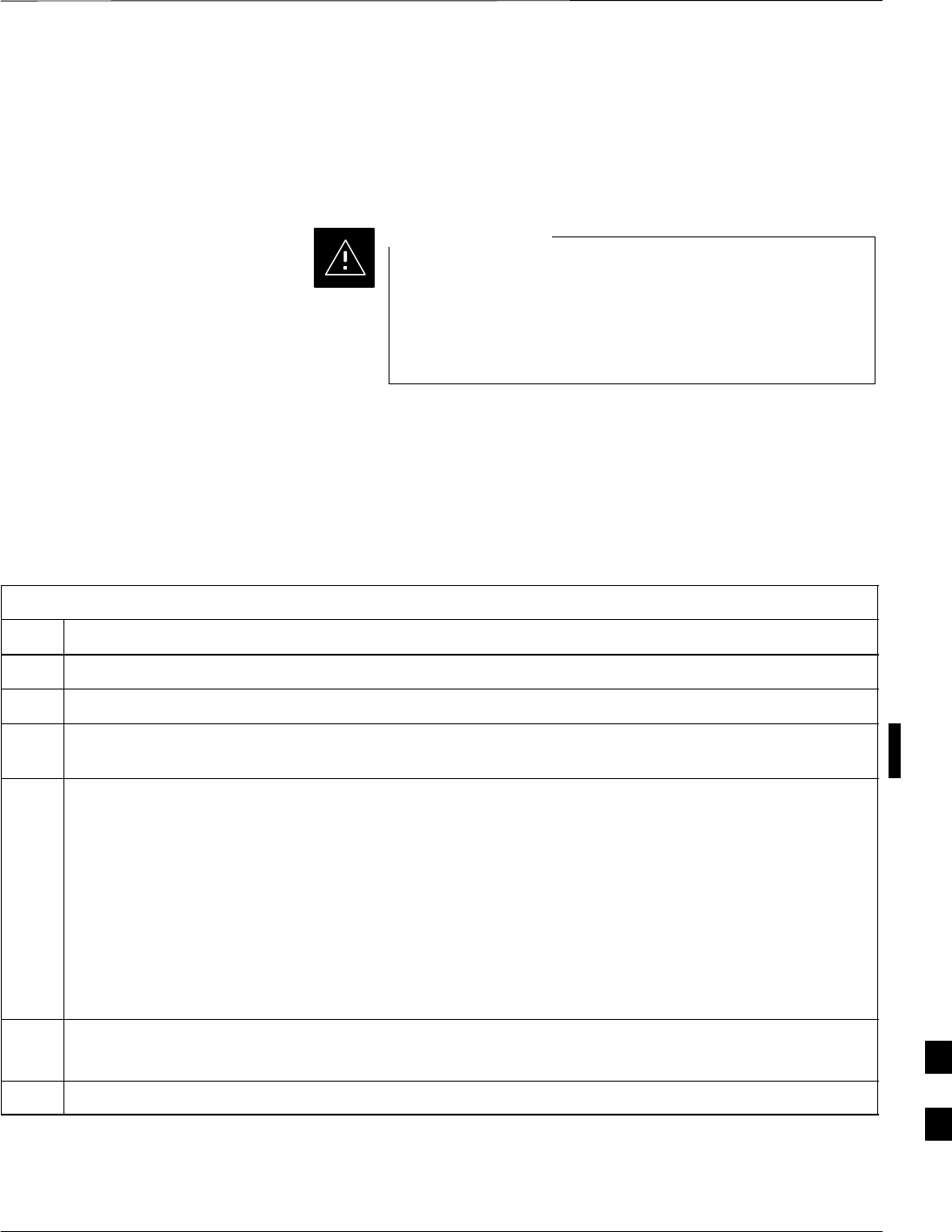
Table 9-4: Procedure to Install HSO or MSO Module
Step Action
4Install HSO Module cover panel by sliding its flange into the slot, closing, and latching it in place.
5Notify operator that the HSO or MSO replacement procedure is completed. Have operator verify that
old alarms have cleared and no new alarms are reported.
6Install BTS front panel cover by setting it in place and pushing on the top and bottom simultaneously.
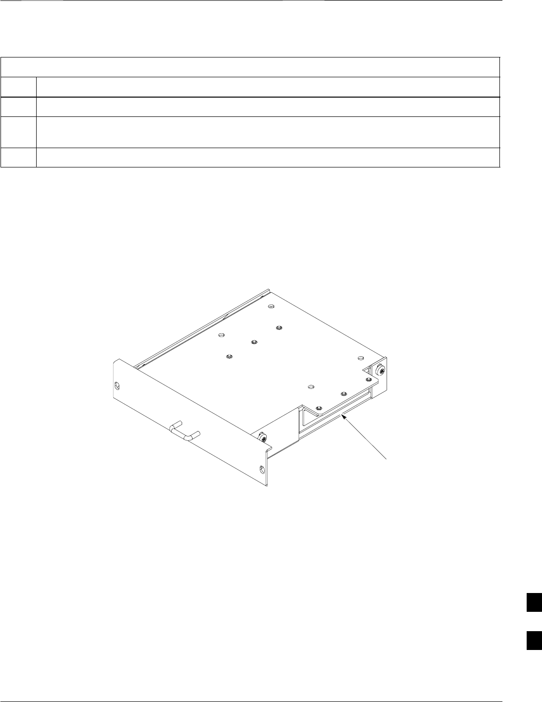
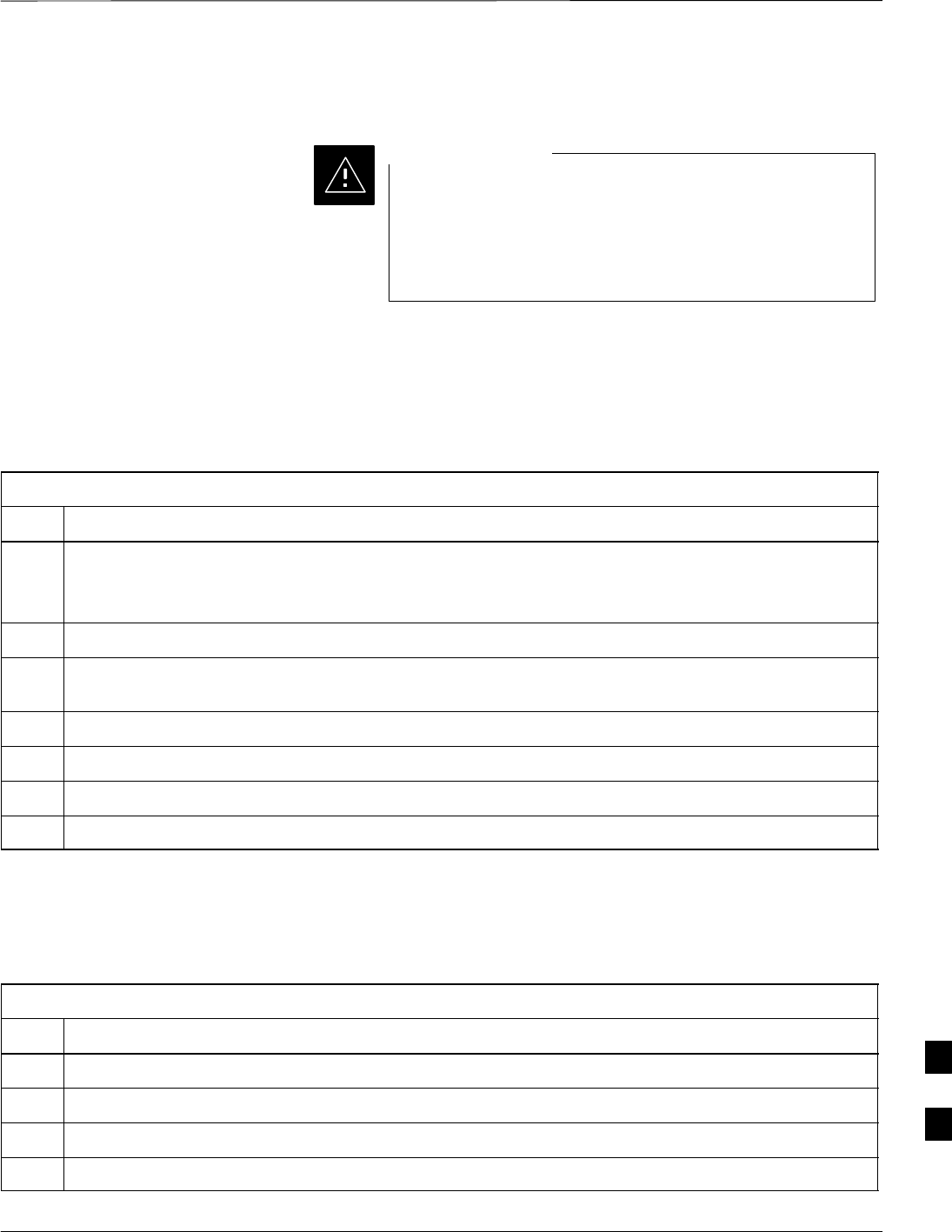
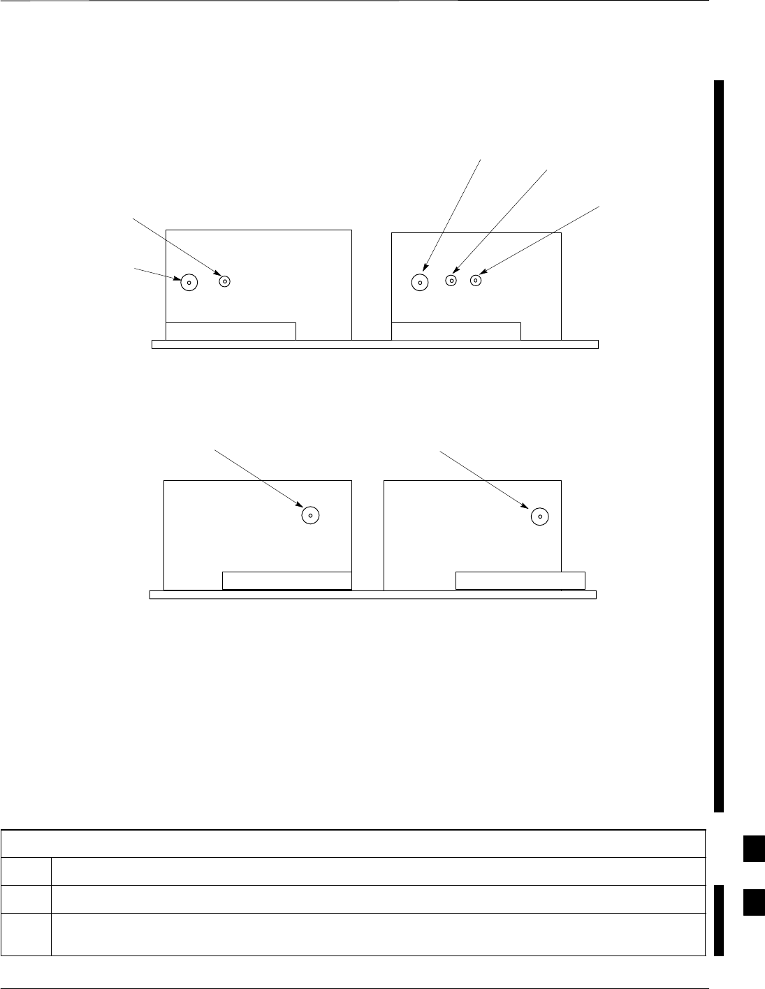
Figure 9-4: HSO or MSO Module
Cable connector
(under flange)
9
High and Medium Stability Oscillator Module – continued
9-10 1X SC480 BTS Hardware Installation, Optimization/ATP, and FRU MAY 2004
PRELIMINARY
ti–cdma–wp–00286–v01–ildoc–ah
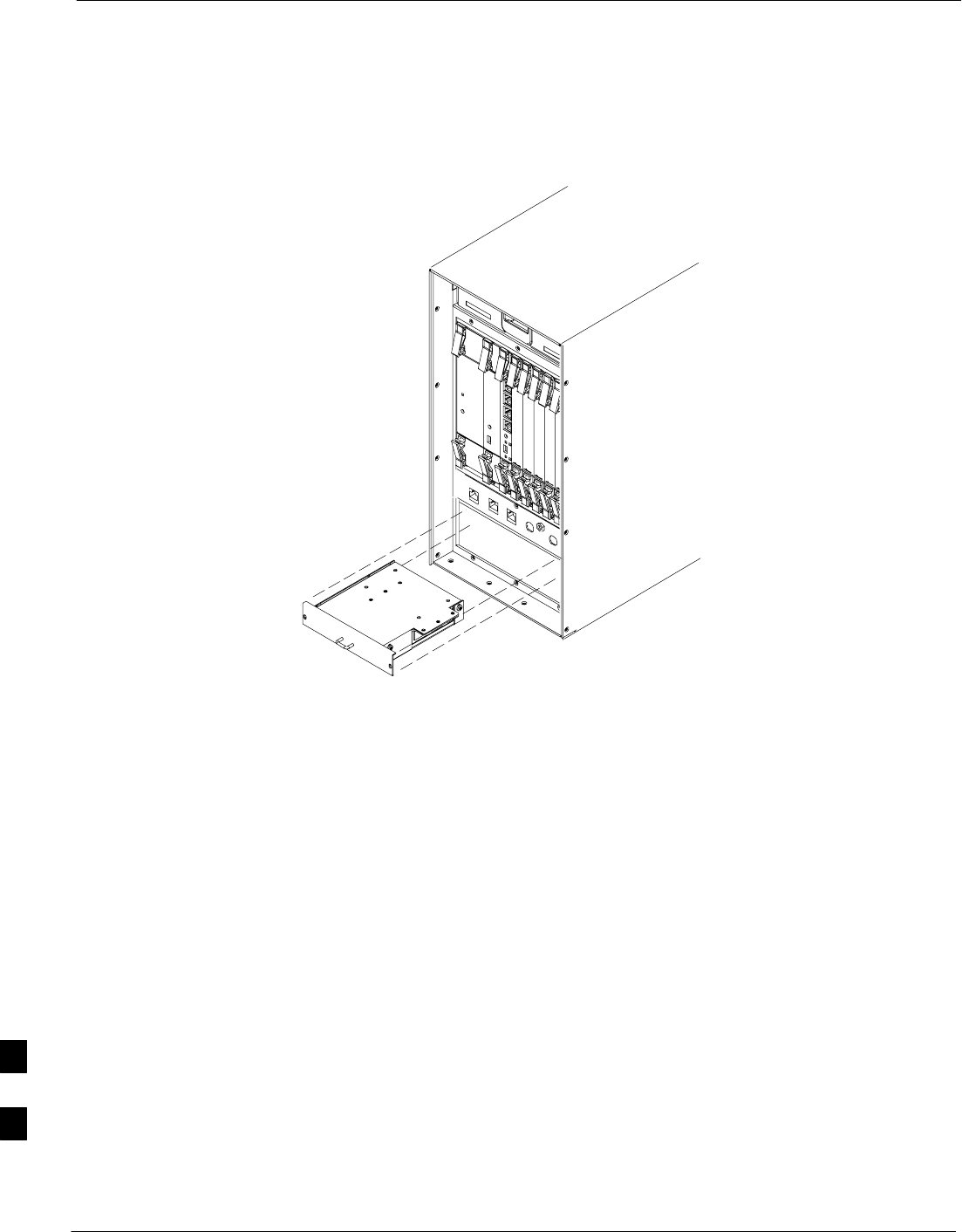
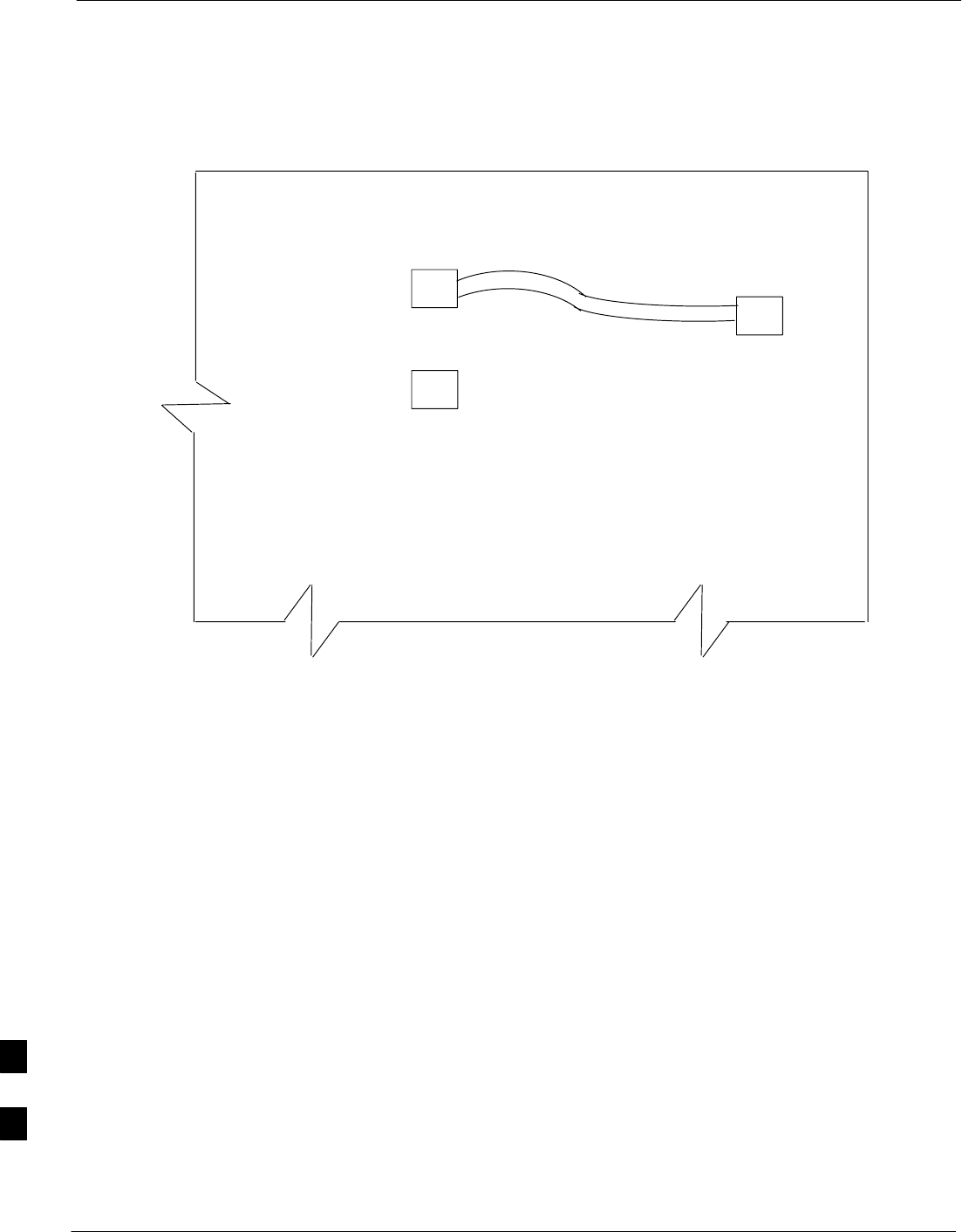
HSO or MSO
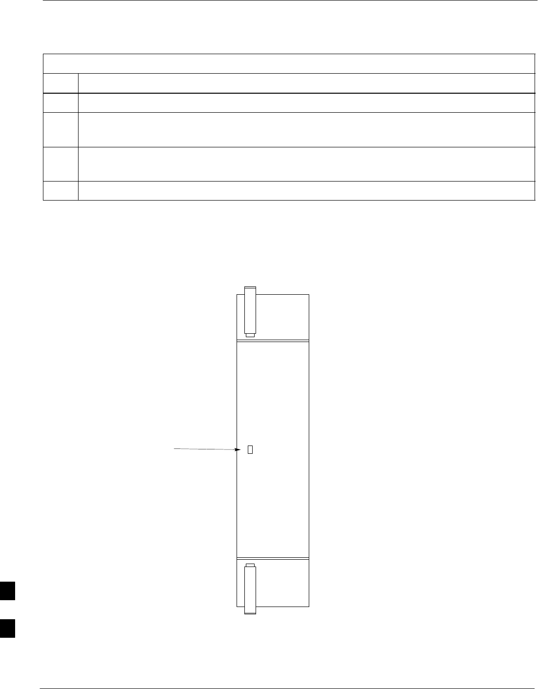
Figure 9-5: HSO or MSO Location
9
Global Positioning System (GPS) Receivers
MAY 2004 1X SC480 BTS Hardware Installation, Optimization/ATP, and FRU 9-11
PRELIMINARY
Introduction
The Compact BTS is configured with either Remote or RF Global
Positioning System (GPS) receiver operation.
For Remote GPS operation, the GPS receiver is located in a
remotely–located GPS head. This head contains a GPS antenna, GPS
receiver, and digital interface. The GPS receiver output signal from the
RGPS head is applied to the Compact BTS. The received signal is routed
to the CSA card.
System Impact/Considerations
If the GPS head has failed, performing the replacement
procedure will not cause an downtime or interrupt call
processing as long as an HSO or MSO has been installed.
If the HSO or MSO has not been “trained” by the GPS for
a minimum of 24 hours, BTS synchronization may not be
maintained for the minimum 24 hours when using the HSO
or 8 hours when using the MSO backup.
IMPORTANT
*
Required Items
Documents
Optimization chapter this manual.
Tools
Appropriate size socket for loosening the pipe/conduit mounting
hardware.
Replacement Unit
One RGPS head (Motorola P/N 0186012H04)
Prerequisite
Coordinate this repair task with the OMC–R operator.
IMPORTANT
*
Replacement Procedure
If desired, record the BTS and RGPS head serial number of the failed
unit in Table 9-55 at the end of this chapter.
Remove RGPS Head
Follow the procedure in Table 9-5 to remove the RGPS Head.
9

Global Positioning System (GPS) Receivers – continued
9-12 1X SC480 BTS Hardware Installation, Optimization/ATP, and FRU MAY 2004
PRELIMINARY
Table 9-5: Procedure to Remove RGPS Head
Step Action
1Notify operator that the RGPS Head replacement procedure is starting and that alarms can be
expected.
2Have the OMC–R operator verify the reference source configuration for the CSA.
* IMPORTANT
Before removing an RGPS Head that has a working RGPS receiver, have the OMC–R operator verify
that the reference source for the CSA is configured for an HSO or MSO.
3Create slack in the RGPS cable so that 0.70 m (2 ft.) of cable extend out of the RGPS Head end of the
mounting pipe/conduit.
NOTE
To prevent twisting of cables, do not unscrew or screw RGPS Head while holding the pipe/conduit.
4Loosen the pipe/conduit mounting hardware until the pipe/conduit is free to be unscrewed from the
RGPS Head.
5Grasp the RGPS Head in one hand and the pipe/conduit in the other.
Unscrew the pipe/conduit from the head and separate.
Grasp the cable just below the head and pull out about 0.5 m (16–inches) of cable out of the
pipe/conduit until the mating cable connectors are exposed.
NOTE
The CSA will automatically switch over to the HSO or MSO approximately 2 seconds after
disconnecting a working RGPS Head. Alarms will be triggered at this time.
Install RGPS Head
Follow the procedure in Table 9-6 to install the RGPS Head.
Table 9-6: Procedure to Install RGPS Head
Step Action
1Connect the cable connector of the replacement RGPS head to the RGPS cable connector.
2Feed the cable slack into the RGPS head end of the mounting pipe/conduit.
3Grasp the RGPS head in one hand and the pipe/conduit in the other.
Being careful not to cross thread the fitting on the RGPS head, screw the pipe/conduit into the head.
Hand tighten only!
4Tighten the pipe/conduit mounting hardware until the pipe/conduit is securely mounted.
5Notify the operator that the replacement procedure has been completed.
Have the operator verify that the original alarms have cleared and that no new alarms are reported.
9
Global Positioning System (GPS) Receivers – continued
MAY 2004 1X SC480 BTS Hardware Installation, Optimization/ATP, and FRU 9-13
PRELIMINARY
WALL MOUNTING
BRACKETS (2)
CLAMP BRACKETS (2)
U–BOLTS
CABLE TO LIGHTNING ARRESTOR
TO SITE I/O INTERFACE (CABLE M)
REFER TO VIEW A FOR
CABLING DETAIL
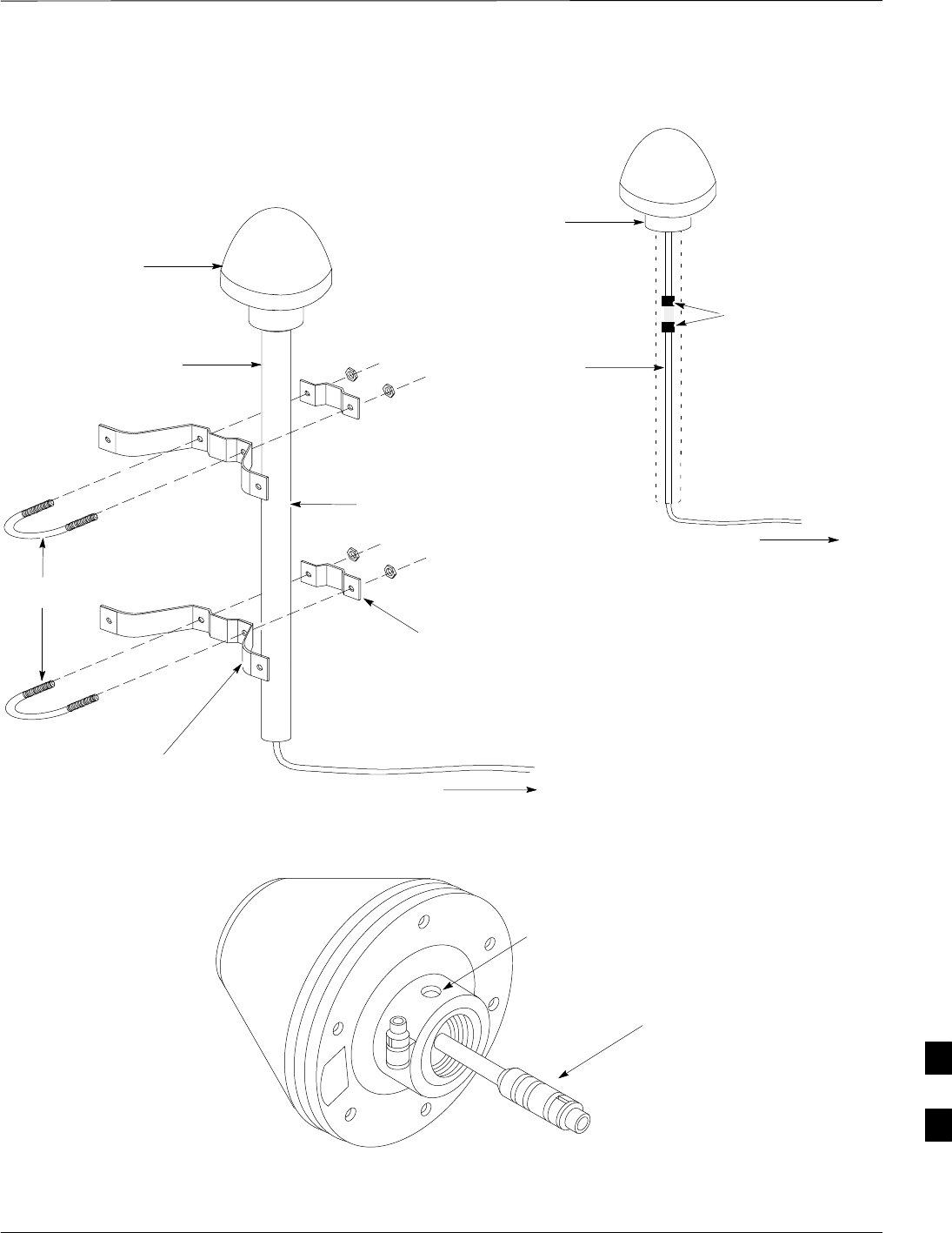
RGPS HEAD WITH
12 PIN MALE
CONNECTOR
MATING
CONNECTORS
RGPS INTERFACE
CABLE WITH 12 PIN
FEMALE CONNECTOR
ON ONE END AND
UNTERMINATED WIRE
ON OTHER END
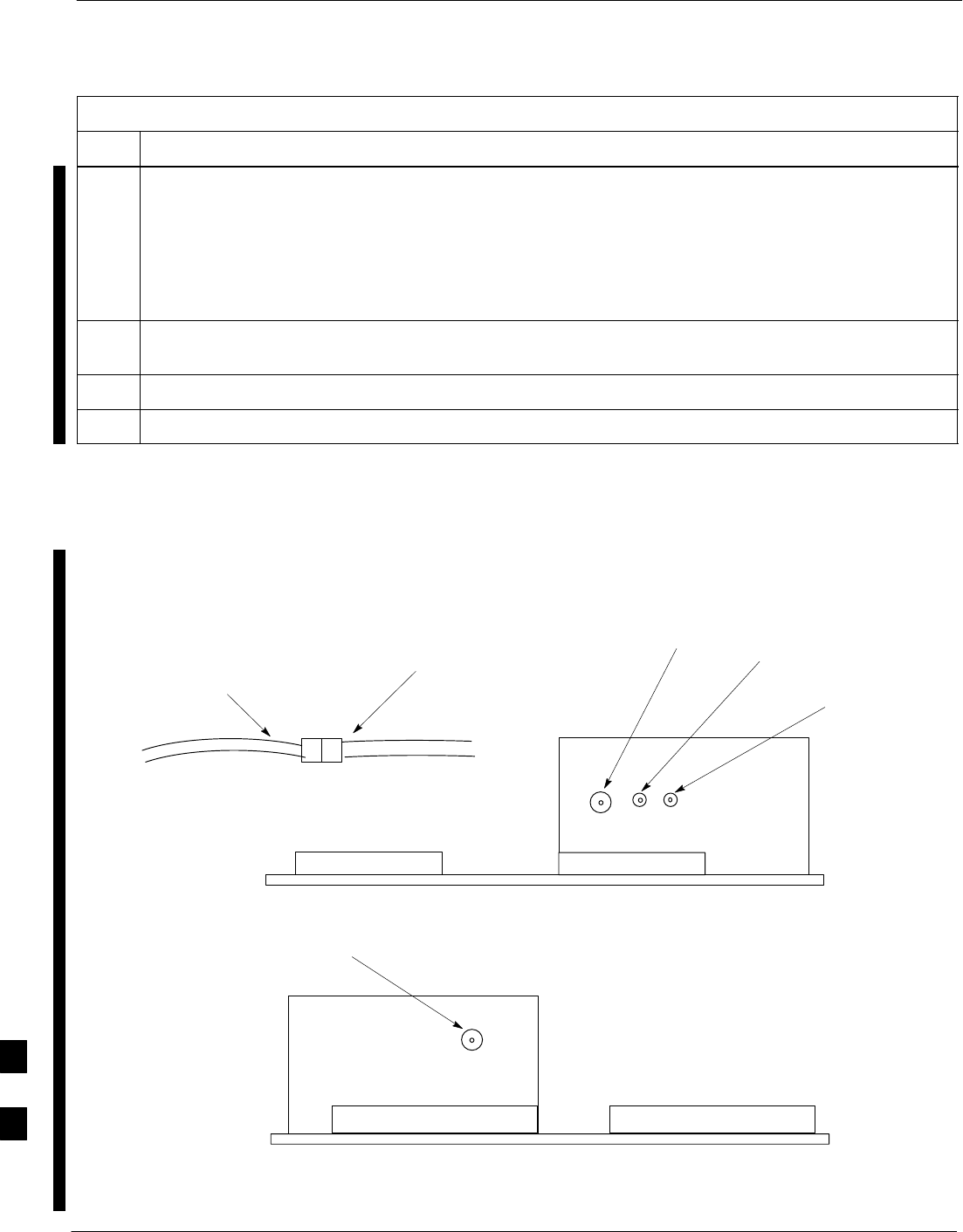
VIEW A
RGPS HEAD
(MOTOROLA PART
NUMBER 0186012H03)1
THREADED MOUNT ADAPTER
12–PIN DEUTSCH TYPE MMP
CONNECTOR
RGPS HEAD
CABLE TO LIGHTNING
ARRESTOR TO SITE I/O
INTERFACE (CABLE M)
1–INCH OD
THREADED
CONDUIT
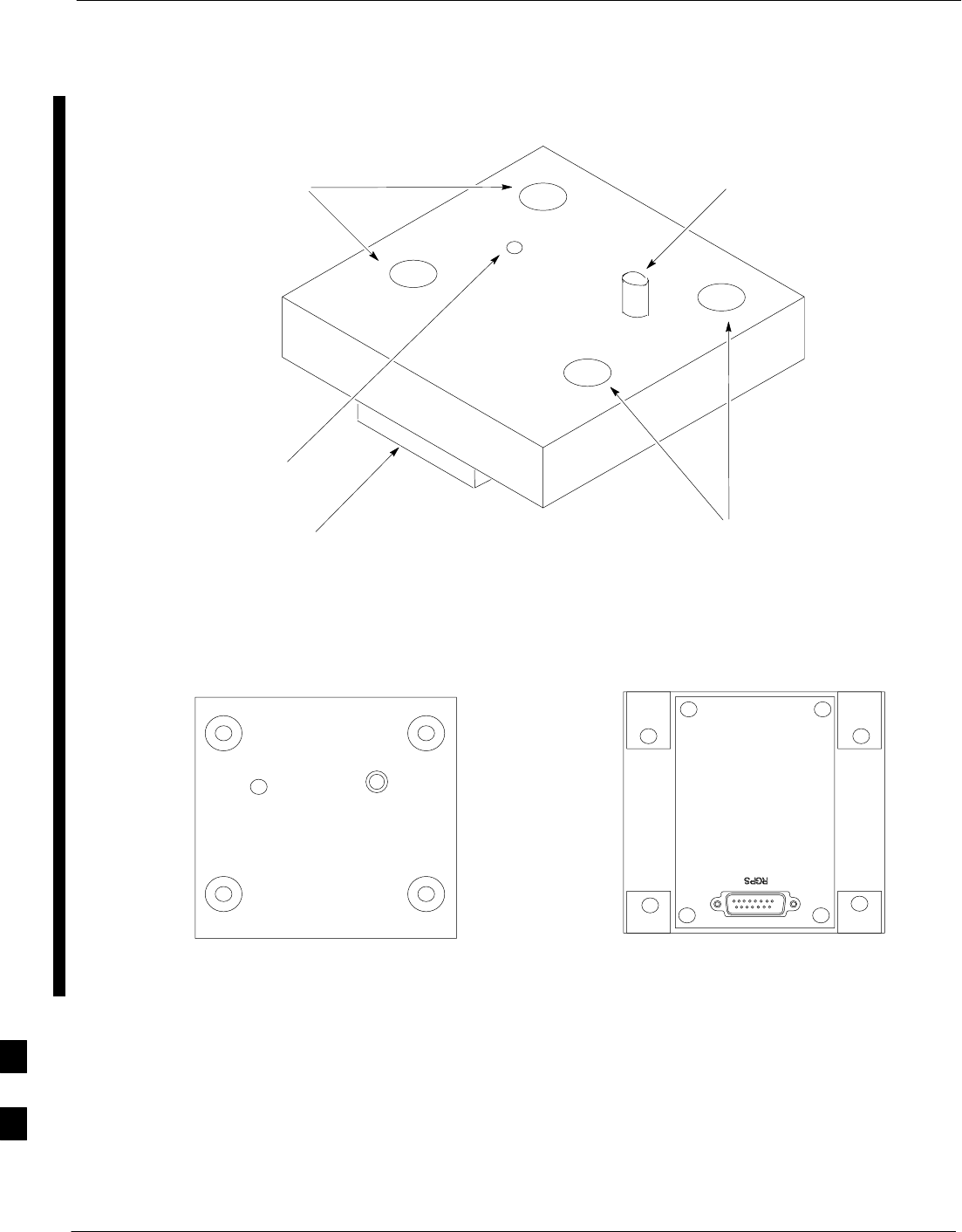
Figure 9-6: RGPS Head and Mounting Pipe/Conduit
NOTE:
1. REPLACEMENT RGPS HEAD
IS MOTOROLA P/N 0186012H04
9
RF–GPS Module
9-14 1X SC480 BTS Hardware Installation, Optimization/ATP, and FRU MAY 2004
PRELIMINARY
Introduction
The procedures in this section cover only the removal and installation of
the RF–GPS Module.
System Impact/Considerations
If the RF–GPS is failing or has failed there will be an interruption in call
processing. The entire site will be down during the replacement of this
component unless an HSO or MSO is in support.
The maximum loss of the RF cable CANNOT exceed
15 dB (assuming 25 dB antenna gain).
IMPORTANT
*
Required Items
Documents
None
Tools
Star screw driver.
Replacement Items
One RF–GPS Module (SGRG4030)
Prerequisite
Coordinate this repair task with the OMC–R operator.
IMPORTANT
*
Contact the OMC–R operator before performing the replacement
procedure. Tell the operator that the RF–GPS module will be replaced
and that alarms can be expected.
Upon completion of the replacement procedure, have the OMC–R
operator verify that old alarms are cleared and that no new ones are
reported.
Replacement Procedure
If desired, record the BTS and RF–GPS serial number of the failed unit
in Table 9-56 at the end of this chapter.
Remove RF–GPS
Follow the procedure in Table 9-7 to remove the RF–GPS.
9

RF–GPS Module – continued
MAY 2004 1X SC480 BTS Hardware Installation, Optimization/ATP, and FRU 9-15
PRELIMINARY
Table 9-7: Procedure to Remove RF–GPS
Step Action
1Notify operator that the RF–GPS module replacement procedure is starting and that alarms can be
expected.
2Put on an ESD wrist strap or other approved grounding device.
3At the rear of the BTS, disconnect RF–GPS cable from its SMA connector. See Figure 9-7.
4Using a T20 bit, remove four M4 screws securing RF–GPS module to the CBIO Board.
5Gently remove RF–GPS module (disconnects it from the RGPS D–connector in the CBIO Board) and
place in/on an anti–static container or surface.
Install RF–GPS
Follow the procedure in Table 9-8 to install the RF–GPS.
Table 9-8: Procedure to Install RF–GPS
Step Action
1Put on an ESD wrist strap or other approved grounding device.
2If not already done, remove new RF–GPS module from its anti–static container
3Remove protective cover from RGPS D–connector.
4Install RF–GPS module onto the CBIO Board, by aligning D–connector on bottom of RF–GPS
module with RGPS D–connector on CBIO Board and gently push down on module. See Figure 9-8.
5Using a T20 bit, secure module to CBIO Board with four M4 screws. Torque screws to 2.3 N–M (20
in–lbs).
6Connect RF–GPS cable to the SMA connector. Torque to 1 N–M (9 in–lbs).
7Notify the operator that the replacement procedure is complete.
9
RF–GPS Module – continued
9-16 1X SC480 BTS Hardware Installation, Optimization/ATP, and FRU MAY 2004
PRELIMINARY
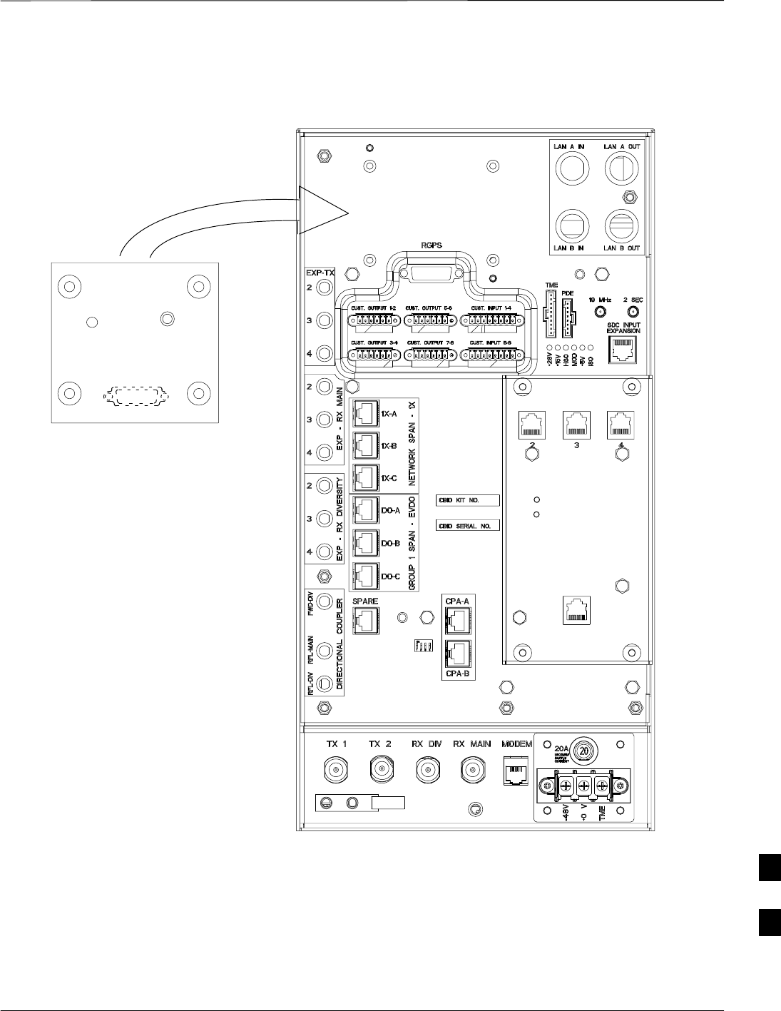
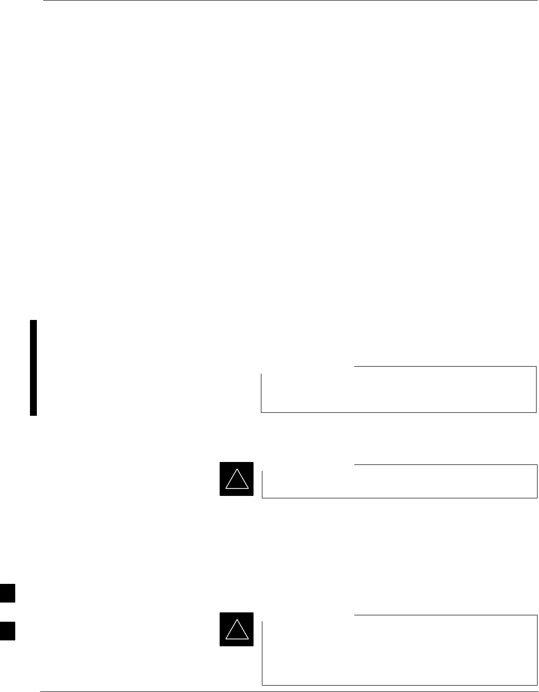
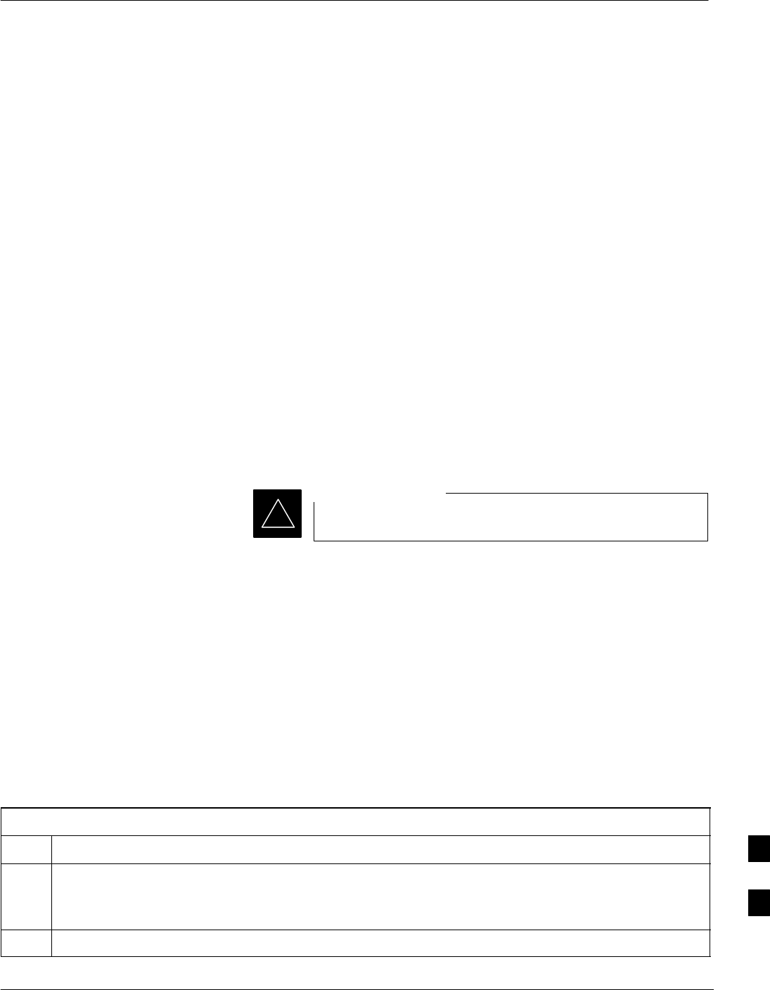
Figure 9-7: RF–GPS Module
RF–GPS IN
PWR
RFGPS SERIAL NO.
RFGPS KIT NO.
TOP VIEW BOTTOM VIEW
SMA
Connector
Screw Holes
Screw Holes
Indicator
RGPS
Connector
9
RF–GPS Module – continued
MAY 2004 1X SC480 BTS Hardware Installation, Optimization/ATP, and FRU 9-17
PRELIMINARY
Figure 9-8: RF–GPS Placement on CBIO Board
RF–GPS plugged
in and secured
with four screws.
RF–GPS IN
PWR
RFGPS SERIAL NO.
RFGPS KIT NO.
ti–cdma–wp–00311–v01–ildoc–ah
EXPANSION FRAME SYNC – OUT
DAISY–CHAIN SYNC – OUT
DAISY–CHAIN POWER
SDCX POWER
SDCX KIT NO.
SDCX SERIAL NO.
9
Power Supply Module (PSM)
9-18 1X SC480 BTS Hardware Installation, Optimization/ATP, and FRU MAY 2004
PRELIMINARY
Introduction
The procedures in this section cover only the Power Supply Module
(PSM). The PSM occupies the first slot in the CCP2 Shelf.
System Impact/Consideration
The PSM supplies DC power to the cards/modules of the CCP2 Shelf. If
the module needed replacing it will cause an interruption in call
processing.
Required Items
Documents
None.
Tools
None.
Replacement Unit
For –48 VDC – One Power Supply Module (SGPN4053)
For +27 VDC – One Power Supply Module (STPN4009)
The connector keying for the PSM is different for each
version to prevent using the wrong module.
NOTE
Prerequisite
Coordinate this repair task with the OMC–R operator.
IMPORTANT
*
Contact the OMC–R operator before performing the replacement
procedure. Tell the operator that the PSM will be replaced and that
alarms can be expected.
Upon completion of the replacement procedure, have the OMC–R
operator verify that old alarms are cleared and that no new ones are
reported.
When this module is removed, the BTS will shut down
because power to CCP2 Shelf will be interrupted. It is
recommended that replacing the PSM be performed during
a maintenance window.
IMPORTANT
*
9
Power Supply Module (PSM) – continued
MAY 2004 1X SC480 BTS Hardware Installation, Optimization/ATP, and FRU 9-19
PRELIMINARY
Replacement Procedure
This procedure requires working around circuitry that is
extremely sensitive to Electrostatic Discharge (ESD). Wear
a conductive, high impedance wrist strap during the
procedure.
Use appropriate safety measures.
CAUTION
If desired, record the BTS and PSM serial number of the failed unit in
Table 9-57 at the end of this chapter.
Remove Power Supply Module
Follow the procedure in Table 9-9 to remove the Power Supply Module.
Table 9-9: Procedure to Remove Power Supply Module
Step Action
n WARNING
Disengaging the PSM from the CCP2 Shelf will cause the site to be shutdown due to the disruption in
power to the shelf.
1Notify operator that the PSM replacement procedure is starting and that alarms can be expected.
2At the front of the BTS, remove the front panel cover by grasping finger grooves at the top and
bottom and pulling simultaneously.
3Put on an ESD wrist strap or other approved grounding device.
4Simultaneously press the locking tabs on both the top and bottom module latches
5Pull the latches out to disengage the module from the shelf and slide the card out.
6Place PSM in/on an anti–static container or surface.
Install Power Supply Module
Follow the procedure in Table 9-10 to install the Power Supply Module.
Table 9-10: Procedure to Install Power Supply Module
Step Action
1Put on an ESD wrist strap or other approved grounding device.
2If not already done, remove new PSM from its anti–static container.
3Insert module and carefully slide into slot and push in until it is seated in the backplane.
4Simultaneously pull both latches forward and slip the tips behind the frame.
table continued on next page
9
Power Supply Module (PSM) – continued
9-20 1X SC480 BTS Hardware Installation, Optimization/ATP, and FRU MAY 2004
PRELIMINARY
Table 9-10: Procedure to Install Power Supply Module
Step Action
5Push the latches in to engage the module with the backplane and lock the tabs.
6Note that the LED turns red briefly, then green.
Green indicates that it has passed all self–tests and is functional.
7Notify the operator that the replacement procedure has been completed.
Have the operator verify that the original alarms have cleared and that no new alarms are reported.
8Install BTS front panel cover by setting it in place and pushing on the top and bottom simultaneously.
Figure 9-9: Power Supply Module (PSM)
PWR/ALM
PWR/ALM
9
Clock Synchronization Alarms Card
MAY 2004 1X SC480 BTS Hardware Installation, Optimization/ATP, and FRU 9-21
PRELIMINARY
Introduction
The procedures in this section cover only the Clock Synchronization
Alarms (CSA) card. The CSA occupies the second slot in the CCP2
Shelf.
System Impact/Considerations
This replacement procedure does require some system downtime. Since
there is no redundancy, call processing will be interrupted during the
time of the replacement.
Required Items
Documents
None.
Tools
None
Replacement Item
One CSA card.
Prerequisite
Coordinate this repair task with the OMC–R operator.
IMPORTANT
*
Contact the OMC–R operator before performing the replacement
procedure. Tell the operator that the CSA card will be replaced and that
alarms can be expected.
Upon completion of the replacement procedure, have the OMC–R
operator verify that old alarms are cleared and that no new ones are
reported.
Replacement Procedure
If desired, record the BTS and CSA serial number of the failed unit in
Table 9-58 at the end of this chapter.
Remove CSA Module
Follow the procedure in Table 9-11 to remove the CSA card.
Table 9-11: Procedure to Remove CSA Module
Step Action
n WARNING
Disengaging the CSA from the CCP2 Shelf will cause the site to be shutdown due to the disruption in
clock timing to the other cards and modules in the BTS.
1Notify operator that the CSA card replacement procedure is starting and that alarms can be expected.
table continued on next page
9

Clock Synchronization Alarms Card – continued
9-22 1X SC480 BTS Hardware Installation, Optimization/ATP, and FRU MAY 2004
PRELIMINARY
Table 9-11: Procedure to Remove CSA Module
Step Action
2Put on the ESD wrist strap or other approved grounding device.
3If not already done, remove BTS front panel cover by grasping finger grooves at the top and bottom
and pulling simultaneously.
4Simultaneously press the locking tabs on both the top and bottom card latches
5Pull the latches out to disengage the card from the shelf and slide the card out.
6Place card in/on an anti–static container or surface.
Install CSA Module
Follow the procedure in Table 9-12 to install the CSA card.
Table 9-12: Procedure to Install CSA Module
Step Action
1Put on the ESD wrist strap or other approved grounding device.
2If not already done, remove new CSA card from its anti–static container.
3Insert card and carefully slide into slot and push in until it is seated in the backplane.
4Simultaneously pull both latches forward and slip the tips behind the frame.
5Push the latches in to engage the card with the backplane and lock the tabs.
6The LED illuminates red briefly, then turns green.
Green indicates that the module has passed all self–tests and is functional.
7Notify the OMC–R operator that the replacement procedure has been completed, and that old alarms
are cleared and no new alarms are reported.
8If there are no other actions required, install BTS front panel cover by setting it in place and pushing
on the top and bottom simultaneously.
9
Clock Synchronization Alarms Card – continued
MAY 2004 1X SC480 BTS Hardware Installation, Optimization/ATP, and FRU 9-23
PRELIMINARY
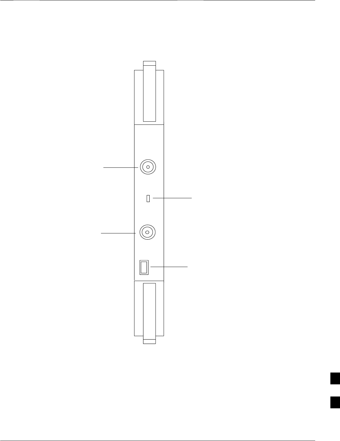
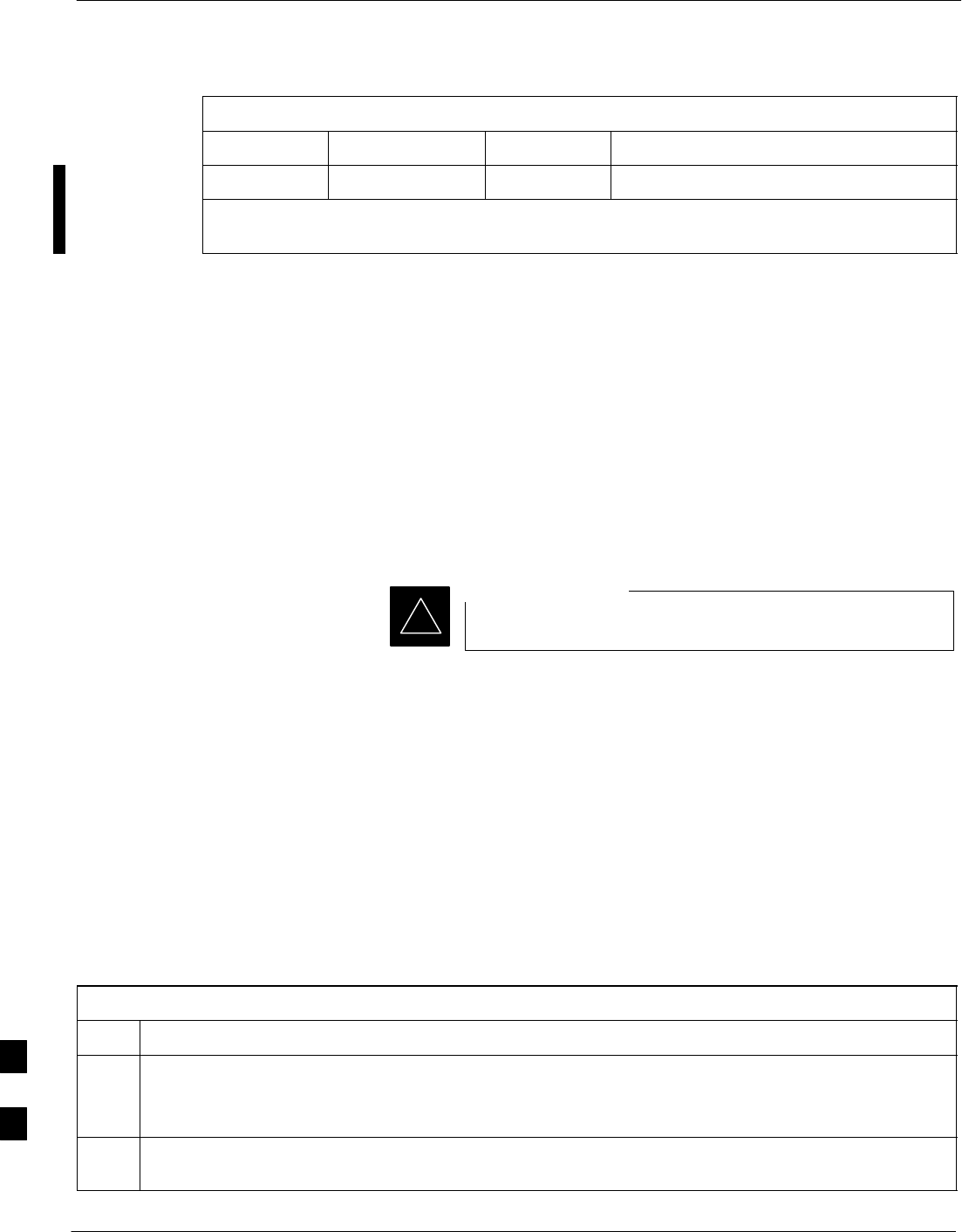
Figure 9-10: Clock Synchronization and Alarm Card
MMI
Frequency Monitor
Synchronization
Monitor
Status/Alarm LED
Man–Machine
Interface
STA/ALM
FREQ. MONITOR
SYNC MONITOR
9
Group Line Interface Card
9-24 1X SC480 BTS Hardware Installation, Optimization/ATP, and FRU MAY 2004
PRELIMINARY
Introduction
The procedures in this section cover only the Group Line Interface
(GLI) 3 card. The GLI3 occupies the third slot in the CCP2 Shelf.
System Impact/Considerations
An interruption in call processing will occur if the GLI3 card is failing
or fails.
Prerequisite
Coordinate this repair task with the OMC–R operator.
IMPORTANT
*
Contact the OMC–R operator before performing the replacement
procedure. Tell the operator that the GLI3 card will be replaced and that
alarms can be expected.
Upon completion of the replacement procedure, have the OMC–R
operator verify that old alarms are cleared and that no new ones are
reported.
When this module is removed, the BTS will shut down
because card interface and communication will be
interrupted. It is recommended that replacing the GLI3 be
performed during a maintenance window.
IMPORTANT
*
Required Items
Documents
This manual for the optimization and acceptance test procedures.
Tools
None
Replacement Item
One GLI3 card (SGLN5975)
Replacement Procedure
This procedure requires working around circuitry that is
extremely sensitive to Electrostatic Discharge (ESD). Wear
a conductive, high impedance wrist strap during the
procedure.
Use appropriate safety measures.
CAUTION
9

Group Line Interface Card – continued
MAY 2004 1X SC480 BTS Hardware Installation, Optimization/ATP, and FRU 9-25
PRELIMINARY
If desired, record the BTS and GLI3 serial number of the failed unit in
Table 9-59 at the end of this chapter.
Remove GLI3 Card
Follow the procedure in Table 9-13 to remove the GLI3 card.
Table 9-13: Procedure to Remove GLI3 Card
Step Action
n WARNING
Disengaging the GLI3 from the CCP2 Shelf will cause the site to be shutdown due to the disruption in
commnuication with the BBX and MCC cards.
1If not already done, remove BTS front panel cover by grasping finger grooves at the top and bottom
and pulling simultaneously.
2Put on the ESD wrist strap or other approved grounding device.
3Notify operator that the GLI3 card replacement procedure is starting and that alarms can be expected.
4Simultaneously press the locking tabs on both the top and bottom card latches
5Pull the latches out to disengage the card from the shelf and slide the card out.
6Place card in/on an anti–static container or surface.
Install GLI3 Card
Follow the procedure in Table 9-14 to install the GLI3 card.
Table 9-14: Procedure to Install GLI3 Card
Step Action
1Put on the ESD wrist strap or other approved grounding device.
2If not already done, remove new GLI3 card from its anti–static container.
3Insert card and carefully slide into slot and push in until it is seated in the backplane.
4Simultaneously pull both latches forward and slip the tips behind the frame.
5Push the latches in to engage the card with the backplane and lock the tabs.
6Check the STATUS and ALARM LEDs:
SThe ALARM LED lights for about 10 seconds while it powers up self–diagnostic test.
SThe STATUS LED lights briefly, indicating that the card has passed self diagnostic tests.
SBoth LEDs should then remain OFF.
table continued on next page
9

Group Line Interface Card – continued
9-26 1X SC480 BTS Hardware Installation, Optimization/ATP, and FRU MAY 2004
PRELIMINARY
Table 9-14: Procedure to Install GLI3 Card
Step Action
NOTE
If the red ALARM LED remains ON, the card may not be fully seated in the backplane. Pull the card
out about halfway, wait about two minutes before reseating. Perform steps 4 and 5.
If the red LED turns back ON after the green LED turns OFF, a new failure condition exists and an
alarm generated.
7Notify operator that the GLI3 replacement procedure is completed. Have operator verify that old
alarms have cleared and no new alarms are reported.
8Using the LMF connected to the MMI port, verify that new GLI3 card has the proper configuration.
9Proceed to Table 9-15.
GLI3 Recovery Procedure
Follow the procedure in Table 9-15 to recover the GLI3 card.
Table 9-15: Procedure to Recover GLI3 Card
Step Action
1At the prompt, enter the following command:
omc–00000>ENABLE GLI–<bts#>–<gli#> UNC
2Display the status of the GLI by entering the following command:
omc–00000>DISPLAY BTS–<bts#> STATUS
3Verify the status of the new GLI3 is INS_ACTIVE.
4If there are no other actions required, install BTS front panel cover by setting it in place and pushing
on the top and bottom simultaneously.
Optimization Requirement
Refer to the Optimization section of this manual and perform the
required procedures.
9
Group Line Interface Card – continued
MAY 2004 1X SC480 BTS Hardware Installation, Optimization/ATP, and FRU 9-27
PRELIMINARY
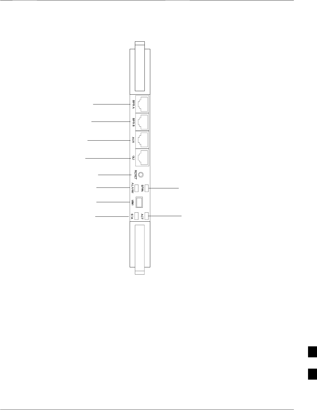
Figure 9-11: Group Line Interface 3 Card
BPR A
BPR B
AUX
GLI
RESET
ALARM
MMI
ACT
SPAN
STA
9

Multi–Channel CDMA Card
9-28 1X SC480 BTS Hardware Installation, Optimization/ATP, and FRU MAY 2004
PRELIMINARY
Introduction
The procedures in this section cover only the Multi–Channel CDMA
(MCC) cards. The MCC–1X cards occupy the fourth, fifth, and sixth
slots (MCC 1, 2, & 3) in the CCP2 Shelf.
If the MCC–DO card is in use, proceed to that section for more
information later in this chapter.
System Impact/Considerations
If an MCC–1X card fails it will cause some interruption in call
processing in the sense that not all calls will be handled. The other
MCC–1X cards may not be able to handle the additional calls thus calls
on the failing or failed card will be dropped.
If an MCC–1X card must be replaced, it must be ensured that it has the
same number of channels as the card being replaced.
MCC Front Panel
PWR/ALM LED
The MCC–1X card has its own alarm (fault) detection circuitry that
controls the state of the PWR/ALM LED. When the LED is:
SGreen –
– OFF – INS_ACT no alarm.
SRed – Power-up or fault condition.
Active LED
The MCC–1X card has circuitry that controls the state of the Active
LED. When the LED is:
SGreen –
– Solid – INS_ACT no alarm.
– Rapidly Flashing – OOS_RAM no alarm.
– Slowly Flashing – OOS_ROM no alarm.
SRed –
– Fault condition or card is in reset.
– Slow flashing (alternating with green) – CHI bus inactive on power
up.
Required Items
Documents
None.
Tools
None.
9
Multi–Channel CDMA Card – continued
MAY 2004 1X SC480 BTS Hardware Installation, Optimization/ATP, and FRU 9-29
PRELIMINARY
Replacement Items
SUp to 3 MCC–1X–16 cards (SGLN6117)
SUp to 3 MCC–1X–32 cards (SGLN6050)
SUp to 3 MCC–1X–48 cards (SGLN6051)
SUp to 3 MCC–1X–64 cards (SGLN6052) (for Packet Backhaul)
Prerequisite
Coordinate this repair task with the OMC–R operator.
IMPORTANT
*
Contact the OMC–R operator before performing the replacement
procedure. Tell the operator that the MCC–1X card will be replaced and
that alarms can be expected.
Upon completion of the replacement procedure, have the OMC–R
operator verify that old alarms are cleared and that no new ones are
reported.
Replacement Procedure
This procedure requires working around circuitry that is
extremely sensitive to Electrostatic Discharge (ESD). Wear
a conductive, high impedance wrist strap during the
procedure.
Use appropriate safety measures.
CAUTION
If desired, record the BTS and MCC serial number of the failed unit in
Table 9-60 at the end of this chapter.
Remove MCC–1X Card
Follow the procedure in Table 9-16 to remove the MCC–1X card.
Table 9-16: Procedure to Remove MCC–1X Card
Step Action
n WARNING
Due to a lack of redundancy, disengaging the MCC cards from the CCP2 Shelf will cause the site to be
shutdown due to the disruption in communication with the GLI3.
1Notify operator that the MCC replacement procedure is starting and that alarms can be expected.
2Put on the ESD wrist strap or other approved grounding device.
3If not already done, remove BTS front panel cover by grasping finger grooves at the top and bottom
and pulling simultaneously.
table continued on next page
9

Multi–Channel CDMA Card – continued
9-30 1X SC480 BTS Hardware Installation, Optimization/ATP, and FRU MAY 2004
PRELIMINARY
Table 9-16: Procedure to Remove MCC–1X Card
Step Action
4Simultaneously press the locking tabs on both the top and bottom card latches
5Pull the latches out to disengage the card from the shelf and slide the card out.
6Place MCC–1X card on/in an anti–static container or surface.
Install MCC–1X Card
Follow the procedure in Table 9-17 to install the MCC–1X card.
Table 9-17: Procedure to Install MCC–1X Card
Step Action
1Put on the ESD wrist strap or other approved grounding device.
2If not already done, remove new MCC–1X card from anti–static container.
3Slide card into slot and simultaneously pull both latches forward and slip the tips behind the frame.
4Push the latches in to engage the card with the backplane and lock the tabs.
5Notify operator that the MCC replacement procedure is completed. Have operator verify that old
alarms have cleared and no new alarms are reported.
6If there are no other actions required, install BTS front panel cover by setting it in place and pushing
on the top and bottom simultaneously.
Optimization Requirement
Refer to the Optimization section of this manual and perform the
required procedures.
9

Multi–Channel CDMA Card – continued
MAY 2004 1X SC480 BTS Hardware Installation, Optimization/ATP, and FRU 9-31
PRELIMINARY
Figure 9-12: MCC 1X Card
PWR/ALM ACTIVE
Power/Alarm LED
Active LED
9

Broadband Transceiver Card
9-32 1X SC480 BTS Hardware Installation, Optimization/ATP, and FRU MAY 2004
PRELIMINARY
Introduction
The procedures in this section cover only the Broad Band Transceiver
1X (BBX–1X) cards. These cards occupy the seventh and eighth slots
(BBX 1 & 4) of the CCP2 Shelf.
System Impact/ Considerations
The Compact BTS is not configured for redundancy, so a failure of the
BBX card will cause an interruption in call processing. It is still
“hot–swappable” like its Macrocell counterparts. Once replacement is
made, optimization procedures will have to be performed.
Front Panel
The BBX–1X card contains the PWR/ALM and ACTIVE LED’s, reset
switch and MMI port connector. A removable lens covers these items
and deters access to the reset switch and MMI port. Refer to Figure 9-13.
PWR/ALM LED
The BBX module has its own alarm (fault) detection circuitry that
controls the state of the PWR/ALM LED. When the LED is:
SGreen –
– Solid – INS_ACT no alarm.
– Slowly Flashing – OOS_ROM no alarm.
– Rapidly Flashing – OOS_RAM no alarm.
SRed – initializing or power-up or alarm condition.
SCombinations
– Long red/Short green– OOS_ROM alarm.
– Short red/Short green – OOS_RAM alarm.
– Long green/Short red – INS_ACT alarm.
SOFF
– No DC power
– The on–board fuse is open.
Active LED
The BBX module has circuitry that controls the state of the Active LED.
When the LED is:
SGreen – Operating in INS_ACTIVE state and keyed. No alarm
condition present.
SRed –
– Color during initial system power–up.
– Operating in FAULT (alarm) state. Alarm condition is present.
9
Broadband Transceiver Card – continued
MAY 2004 1X SC480 BTS Hardware Installation, Optimization/ATP, and FRU 9-33
PRELIMINARY
Required items
Documents
This manual for optimization and acceptance test procedures.
Tools
None
Replacement Unit
One or two 800 MHz BBX–1X card (SGLF4133)
Prerequisite
Coordinate this repair task with the OMC–R operator.
IMPORTANT
*
Contact the OMC–R operator before performing the replacement
procedure. Tell the operator that the BBX–1X card will be replaced and
that alarms can be expected.
Upon completion of the replacement procedure, have the OMC–R
operator verify that old alarms are cleared and that no new ones are
reported.
Replacement Procedure
This procedure requires working around circuitry that is
extremely sensitive to Electrostatic Discharge (ESD). Wear
a conductive, high impedance wrist strap during the
procedure.
Use appropriate safety measures.
CAUTION
If desired, record the BTS and BBX–1X serial number of the failed unit
in Table 9-61 at the end of this chapter. BBX 1 and 4 will be present if
BTS is configured for two carriers; otherwise, only BBX 1 will be
present.
9

Broadband Transceiver Card – continued
9-34 1X SC480 BTS Hardware Installation, Optimization/ATP, and FRU MAY 2004
PRELIMINARY
Remove BBX–1X Card
Follow the procedure in Table 9-18 to remove the BBX–1X card.
Table 9-18: Procedure to Remove BBX–1X Card
Step Action
n WARNING
Due to a lack of redundancy, disengaging the BBX card(s) from the CCP2 Shelf will cause the site to
be shutdown due to the disruption in communication with the GLI3 and loss of carrier.
1Notify operator that the BBX–1X card replacement procedure is starting and that alarms can be
expected.
2Put on the ESD wrist strap or other approved grounding device.
3If not already done, remove BTS front panel cover by grasping finger grooves at the top and bottom
and pulling simultaneously.
4Simultaneously press the locking tabs on both the top and bottom card latches
5Pull the latches out to disengage the card from the shelf and slide the card out.
6Place on/in an anti–static container or surface.
Install BBX–1X Card
Follow the procedure in Table 9-19 to install the BBX–1X card.
Table 9-19: Procedure to Install BBX–1X Card
Step Action
1Put on the ESD wrist strap or other approved grounding device.
2If not already done, remove new BBX–1X card from anti–static container.
3Slide card into slot and simultaneously pull both latches forward and slip the tips behind the frame.
4Push the latches in to engage the card with the backplane and lock the tabs.
5Notify operator that the BBX–1X replacement procedure is completed. Have operator verify that old
alarms have cleared and no new alarms are reported.
6If there are no other actions required, install BTS front panel cover by setting it in place and pushing
on the top and bottom simultaneously.
Optimization Requirement
Refer to the Optimization section of this manual and perform the
required procedures.
9

Broadband Transceiver Card – continued
MAY 2004 1X SC480 BTS Hardware Installation, Optimization/ATP, and FRU 9-35
PRELIMINARY
Figure 9-13: BBX–1X Card
PWR/ALM ACTIVE
9

Compact BTS Multi–Coupler Preselector Card
9-36 1X SC480 BTS Hardware Installation, Optimization/ATP, and FRU MAY 2004
PRELIMINARY
Introduction
The procedures in this section cover only the Multi–Coupler Preselector
Card (cMPC). The cMPC occupies the ninth slot of the CCP2 Shelf.
cMPC PWR/ALM LED States
The cMPC has a dual color (green & red) power/alarm (PWR/ALM)
status indicator LED located on its front panel. The card has its own
alarm (fault) detection circuitry that controls what is displayed on the
LED. Table 9-20 lists these states. Refer to Figure 9-14.
Table 9-20: cMPC PWR/ALM LED State
LED State Device State
Steady GREEN Operating normally
Steady RED 1. Displayed during initial
power– up.
2. Operating in a Fault condition.
OFF No DC power to card.
System Impact/Considerations
An interruption in call processing, due to the RX signal path being
broken, will occur if the cMPC must be replaced due to total failure or
marginal operation.
Required items
Documents
This manual for optimization and acceptance test procedures.
Tools
None
Replacement Unit
One cMPC (STLF4109)
Prerequisite
Coordinate this repair task with the OMC–R operator.
IMPORTANT
*
Contact the OMC–R operator before performing the replacement
procedure. Tell the operator that the Compact MPC will be replaced and
that alarms can be expected.
9
Compact BTS Multi–Coupler Preselector Card – continued
MAY 2004 1X SC480 BTS Hardware Installation, Optimization/ATP, and FRU 9-37
PRELIMINARY
Upon completion of the replacement procedure, have the OMC–R
operator verify that old alarms are cleared and that no new ones are
reported.
Replacement Procedure
This procedure requires working around circuitry that is
extremely sensitive to Electrostatic Discharge (ESD). Wear
a conductive, high impedance wrist strap during the
procedure.
Use appropriate safety measures.
CAUTION
Before Beginning
If desired, record the BTS and cMPC serial number of the failed unit in
Table 9-62 at the end of this chapter.
Remove cMPC
Follow the procedure in Table 9-21 to remove the cMPC.
Table 9-21: Procedure to Remove cMPC
Step Action
1Notify operator that the cMPC replacement procedure is starting and that alarms can be expected.
2Put on an ESD wrist strap or other approved grounding device.
3If not already done, remove BTS front panel cover by grasping finger grooves at the top and bottom
and pulling simultaneously.
4Simultaneously press the locking tabs on both the top and bottom card latches
Pull the latches out to disengage the card from the shelf and slide the card out far enough to disconnect
the RF cabling.
* IMPORTANT
If the BTS is set up for 2 PAs, then there will be 6 RF cables (fitted with QMA connectors) to
disconnect.
Recommend that the cables be disconnected either from top–to–bottom or bottom–to–top. This will
be important when re–connecting the cables.
At the rear of the card the jumper will be connected to the upper of the two RF connections
5Cables are labeled and color coded, if not, then tag each cable as it is disconnected.
Once cables are disconnected, pull out card.
6Place in/on an anti–static container or surface.
Install cMPC
Follow the procedure in Table 9-22 to install the cMPC.
9

Compact BTS Multi–Coupler Preselector Card – continued
9-38 1X SC480 BTS Hardware Installation, Optimization/ATP, and FRU MAY 2004
PRELIMINARY
Table 9-22: Procedure to Install cMPC
Step Action
1Put on an ESD wrist strap or other approved grounding device.
2If not already done, remove new cMPC from its anti–static container.
3Verify that the cMPC is set up for using 1 or 2 Compact PAs. See Figure 9-15.
SFor 1 PA, the jumper should be connected to the “Default” RF connector.
SFor 2 PAs, the jumper should be connected to the “Alternate” RF connector.
* IMPORTANT
To insert the cMPC with minimum of trouble, make sure the RF cabling is held away towards the side
of the frame in single file and in order they were disconnected.
4Insert card and carefully slide into slot far enough to attach cables.
Attach RF cables (each cable is labeled and color coded)
5Simultaneously pull both latches forward and slip the tips behind the frame.
6Push the latches in to engage the card with the backplane and lock the tabs.
7Note that the LED turns red briefly, then green.
Green indicates that it has passed all self–tests and is functional.
8Notify operator that the cMPC replacement procedure is completed. Have operator verify that old
alarms have cleared and no new alarms are reported.
9If no other action is needed, install BTS front panel cover by setting it in place and pushing on the top
and bottom simultaneously.
9

Compact BTS Multi–Coupler Preselector Card – continued
MAY 2004 1X SC480 BTS Hardware Installation, Optimization/ATP, and FRU 9-39
PRELIMINARY
Figure 9-14: Compact Multi–Coupler Preselector Card
POWER/ALARM LED
PWR/ALM
9
Compact BTS Multi–Coupler Preselector Card – continued
9-40 1X SC480 BTS Hardware Installation, Optimization/ATP, and FRU MAY 2004
PRELIMINARY
Figure 9-15: Compact Multi–Coupler Preselector Card Jumper Connection
DEFAULT
ALTERNATE
Compact MPC shown is set for 1 Power Amplifier
P/O cMPC
9

MCC Data Only (MCC–DO) Card
MAY 2004 1X SC480 BTS Hardware Installation, Optimization/ATP, and FRU 9-41
PRELIMINARY
Introduction
The procedures in this section cover only the MCC Data Only
(MCC–DO) card. If in use, this card utilizes MCC slots 1 and 2, with
slot 3 containing an MCC–1X card or a filler panel.
EV–DO FRU Information
If there are conflicts between the procedures presented here and the
material presented in 1xEV–DO Field Replaceable Unit (FRU)
Procedures – 68P09257A99, the manual takes precedence.
System Impact/Considerations
If the Multi–Channel CDMA Data Only card fails or is removed from
service, there will be an interruption in call processing.
LED States
The MCC–DO card uses four front panel LEDs to indicate its status.
Table 9-23 lists the states of the MCC–DO LEDs.
Table 9-23: MCC–DO LED States
LED Color Status SPAN
Green ON INS or INS_SBY or INS_ACT
PWR/ALM ON Not installed or OOS.
Red Blinking Installed in wrong slot.
–– OFF Off
Green ON INS_ACT
Blinking OOS or INS_SBY
Red ON Not Initialized.
ACT Blinking Installed in wrong slot.
Orange ON INS
–– OFF Off
Red ON Major alarms on a provisioned span.
SPAN Orange ON Minor alarms on a provisioned span.
Green ON No alarms on a provisioned span.
–– OFF No Provisioned span.
Orange ON Both ENET and TAT links are up.
ENET Green ON Either ENET or TAT link is up.
table continued on next page
9
MCC Data Only (MCC–DO) Card – continued
9-42 1X SC480 BTS Hardware Installation, Optimization/ATP, and FRU MAY 2004
PRELIMINARY
Table 9-23: MCC–DO LED States
LED SPANStatusColor
–– OFF Both ENET and TAT link are down.
NOTE: In the case of some spans on a given MCC–DO having Yellow alarms, and other
spans having Red alarms, a Red Alarm state should be indicated.
Required Items
Documents
None.
Tools
None.
Replacement Items
One MCC–Data Only card (SGLN6146)
Prerequisite
Coordinate this repair task with the OMC–R operator.
IMPORTANT
*
Contact the OMC–R operator before performing the replacement
procedure. Tell the operator that the MCC–DO card will be replaced and
that alarms can be expected.
Upon completion of the replacement procedure, have the OMC–R
operator verify that old alarms are cleared and that no new ones are
reported.
Replacement Procedure
If desired, record the BTS and MCC–DO serial number of the failed unit
in Table 9-63 at the end of this chapter.
Remove MCC–DO Card
Follow the procedure in Table 9-24 to remove the MCC–DO card.
Table 9-24: Procedure to Remove MCC–DO Card
Step Action
n WARNING
Disengaging the MCC–DO card from the CCP2 Shelf will cause the site to be shutdown due to the
disruption in signal processing.
1Notify operator that the MCC–DO card replacement procedure is starting and that alarms can be
expected.
table continued on next page
9

MCC Data Only (MCC–DO) Card – continued
MAY 2004 1X SC480 BTS Hardware Installation, Optimization/ATP, and FRU 9-43
PRELIMINARY
Table 9-24: Procedure to Remove MCC–DO Card
Step Action
2Put on the ESD wrist strap or other approved grounding device.
3If not already done, remove BTS front panel cover by grasping finger grooves at the top and bottom
and pulling simultaneously.
4If not already done, label cables prior to disconnecting them from front panel connectors.
5Simultaneously press the locking tabs on both the top and bottom card latches
6Pull the latches out to disengage the card from the shelf and slide the card out.
7Place in/on an anti–static container or surface.
Install MCC–DO Card
Follow the procedure in Table 9-25 to install the MCC–DO card.
Table 9-25: Procedure to Install MCC–DO Card
Step Action
1Put on the ESD wrist strap or other approved grounding device.
2If not already done, remove new MCC–DO card from anti–static container.
3Slide card into slot and simultaneously pull both latches forward and slip the tips behind the frame.
4Push the latches in to engage the card with the backplane and lock the tabs.
5Note that the PWR/ALM LED turns red briefly, then green.
Green indicates that it has passed all self–tests and is functional.
6Connect cabling to front panel connectors.
7Notify operator that the MCC–DO replacement procedure is completed. Have operator verify that old
alarms have cleared and no new alarms are reported.
8If there are no other actions required, install BTS front panel cover by setting it in place and pushing
on the top and bottom simultaneously.
9
MCC Data Only (MCC–DO) Card – continued
9-44 1X SC480 BTS Hardware Installation, Optimization/ATP, and FRU MAY 2004
PRELIMINARY
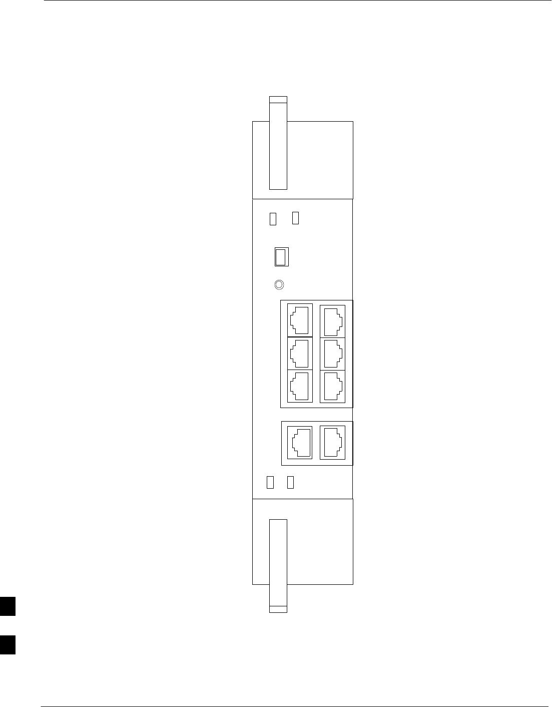
Figure 9-16: MCC–DO Card
NOTE:
1. The DO card physically occupies
MCC slots 1 & 2, but only plugs into
one backplane connector
ENET
ACT
MMI ENET
TAT
GRP3
SPAN
GRP2
SPAN
GRP1
SPAN
SINGLE
DUAL
SPAN
PWR/ALM RESET
9

Compact BTS Input and Output Board
MAY 2004 1X SC480 BTS Hardware Installation, Optimization/ATP, and FRU 9-45
PRELIMINARY
Introduction
The procedures in this section cover only the removal and installation of
the Compact BTS Input and Output (CBIO) Board.
System Impact/Considerations
If the CBIO board is failing or has failed there will be an interruption in
call processing. The entire site will be down for replacement of this
component.
CBIO Indicators
The CBIO Board has six indicators that provide status of several
components of the BTS. The six LEDs are +28V, +15V, HSO, MOD,
+5V, and ISO.
+28V LED
The +28V LED indicates the status of the DC power that is supplied to
the Remote GPS or the RF GPS module. This LED will come on after
the CSA initializes. When the CSA is trying to determine the cable
delay, this LED will go OFF and ON, but it should stay ON once the
delay is successfully completed. If the LED remains OFF, it may
indicate a problem with either the RGPS or RF GPS, or the CSA FRU.
+15V LED
The +15V LED indicates the status of the DC power that is coming from
the DC–DC converter module to the CBIO Board. This LED should
always be ON, unless there is a blown fuse on the CBIO Board.
HSO LED
The HSO LED indicates the status of the DC power that is supplied to
the HSO or MSO module. This LED will be OFF, if the HSO or MSO
is not connected; otherwise, it is ON. Faulty operation of the LED may
be related to problems with the main +15V supply to the CBIO Board,
also indicated by the +15V LED.
MOD LED
The MOD LED indicates the status of the DC power that is supplied to
the modem module. However, this LED is not dependent on whether the
modem module is plugged in or not, and should be always ON. If the
CBIO +5V supply is okay, then the LED being OFF could indicate a
problem with the modem module, the wiring, or a resettable fuse on the
CBIO Board.
+5V LED
The +5V LED indicates the status of the DC power that is coming from
the DC–DC converter module to the CBIO Board. This LED should
always be ON, unless there is a blown fuse on the CBIO Board.
9
Compact BTS Input and Output Board – continued
9-46 1X SC480 BTS Hardware Installation, Optimization/ATP, and FRU MAY 2004
PRELIMINARY
ISO LED
The ISO LED indicates the status of the isolated DC voltage that is used
for the customer inputs. This LED should always be ON, if the +5V
supply to the CBIO Board is okay. If the LED is OFF, it indicates a
problem on the CBIO Board.
Required Items
Documents
None
Tools
Screwdriver with T20 star bit
Replacement Items
One CBIO Board.
Prerequisite
Coordinate this repair task with the OMC–R operator.
IMPORTANT
*
Contact the OMC–R operator before performing the replacement
procedure. Tell the operator that the CBIO will be replaced and that
alarms can be expected.
Upon completion of the replacement procedure, have the OMC–R
operator verify that old alarms are cleared and that no new ones are
reported.
Replacement Procedure
If desired, record the BTS and CBIO Board serial number of the failed
unit in Table 9-64 at the end of this chapter.
Remove CBIO Board
Follow the procedure in Table 9-26 to remove the CBIO Board.
To perform the following procedure, the BTS must be
removed from the Mounting Plate.
NOTE
Table 9-26: Procedure to Remove CBIO Board
Step Action
1Notify operator that the CBIO Board replacement procedure is starting and that alarms can be
expected.
2 Perform the Site Shutdown procedure in Table 10-2.
table continued on next page
9

Compact BTS Input and Output Board – continued
MAY 2004 1X SC480 BTS Hardware Installation, Optimization/ATP, and FRU 9-47
PRELIMINARY
Table 9-26: Procedure to Remove CBIO Board
Step Action
n WARNING
By pulling out the circuit breaker, power to the BTS will be interrupted, causing the BTS to go off
line.
3Disengage DC power to the BTS by pulling out the 20 A breaker at the rear of the BTS.
4If possible, turn off DC power at the source. Verify that DC power source is OFF.
5Disconnect all cabling to the BTS.
6Put on the ESD wrist strap.
7At the rear of the BTS, remove the four M4 screws securing the SDCX or SDCX cover plate to the
CBIO Board. Gently remove SDCX module from the CBIO connector or SDCX cover plate.
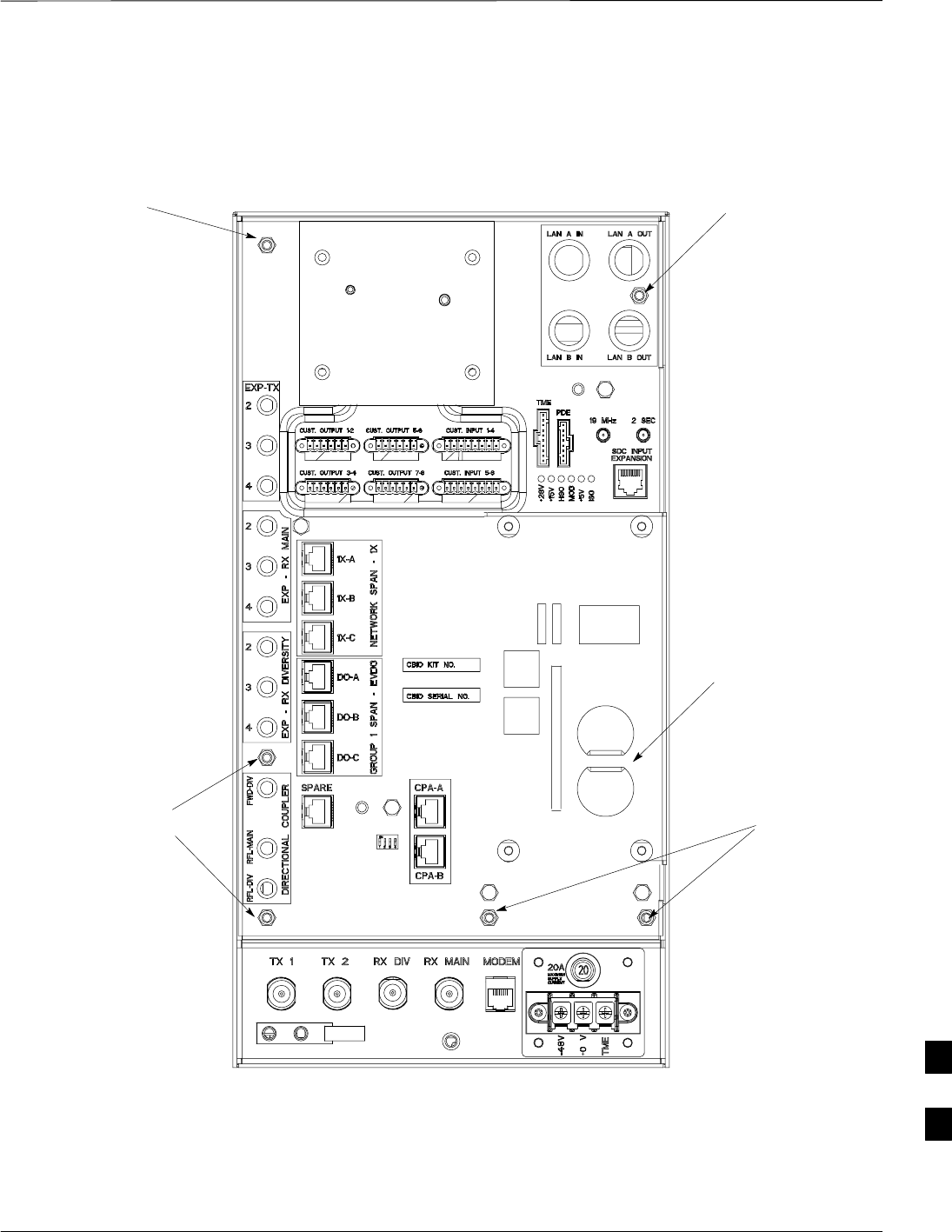
8Use a driver with a T20 star bit to remove 6 M4 screws securing CBIO to housing. See Figure 9-17.
* IMPORTANT
DO NOT yank out the CBIO Board, there are cables connected at the bottom rear side of the board.
9Grasp holes and gently pull on CBIO Board to disengage it from the backplane. See Figure 9-17.
Note that there are internal cables connected at the bottom.
10 If not already done, label internal cables before disconnecting them.
11 Remove CBIO Board and place in an anti–static container.
Install CBIO Board
Follow the procedure in Table 9-27 toinstall the CBIO Board.
Table 9-27: Procedure to Install CBIO Board
Step Action
1Put on the ESD wrist strap.
2If not already done, remove CBIO Board from its anti–static container.
3Set CBIO Board onto rear of BTS and connect the internal cables, in the same order as previously
connected.
4Carefully align the CBIO panel to the frame and gently seat the CBIO connector into the backplane
connector.
5Once aligned, with one hand grasp BTS and with the other hand gently push the CBIO until it sets up
against the housing.
6Use a driver with a T20 star bit to secure the CBIO to the frame using 6 M4 screws. Torque screws to
2.3 N–M (20 in–lbs). See Figure 9-17.
7Install SDCX or SDCX cover plate and secure to CBIO using 4 M4 screws. Torque screws to 2.3
N–M (20 in–lbs).
table continued on next page
9

Compact BTS Input and Output Board – continued
9-48 1X SC480 BTS Hardware Installation, Optimization/ATP, and FRU MAY 2004
PRELIMINARY
Table 9-27: Procedure to Install CBIO Board
Step Action
8Disengage from the ESD wrist strap.
9Connect all external cabling.
10 Verify that DC power source is OFF before re–connecting to the BTS.
Turn on DC power source.
11 Notify the operator know that the replacement procedure is completed, and that power up will begin
shortly.
12 Allow the BTS to power up by pushing in the 20 A circuit breaker at the rear of the BTS.
13 Perform the Site Startup procedure in Table 10-5.
14 Perform an optimization of the cards, using the procedures in the Optimization/ATP section of this
manual.
15 After BTS is optimized and is operating within normal parameters, install the BTS front cover panel
by setting it in place and pushing on the top and bottom simultaneously.
16 Notify operator that optimization is complete.
9
Compact BTS Input and Output Board – continued
MAY 2004 1X SC480 BTS Hardware Installation, Optimization/ATP, and FRU 9-49
PRELIMINARY
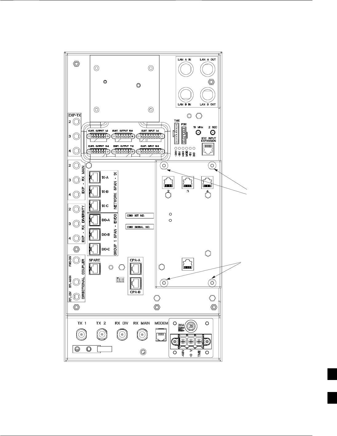
Figure 9-17: CBIO Board with SDCX Removed
ti–cdma–wp–00311–v01–ildoc–ah
RF–GPD IN
PWR
Screws to
remove
Screws to
remove
Screw to
remove
Screw to
remove
Grasp holes
with forefinger
and thumb.
SDCX Board or
Cover Plate
Removed
9
SDCX Module
9-50 1X SC480 BTS Hardware Installation, Optimization/ATP, and FRU MAY 2004
PRELIMINARY
Introduction
The procedures in this section cover only the removal and installation of
the Synchronization Daisy–Chaining and eXpansion (SDCX) Module.
System Impact/Considerations
If the SDCX fails it will cause a disruption in call processing by
upsetting the timing of the BTSs.
Required Items
Documents
None
Tools
Star screw driver.
Replacement Items
One SDCX Module (SGLN6153)
Prerequisite
Coordinate this repair task with the OMC–R operator.
IMPORTANT
*
Contact the OMC–R operator before performing the replacement
procedure. Tell the operator that the SDCX module will be replaced and
that alarms can be expected.
Upon completion of the replacement procedure, have the OMC–R
operator verify that old alarms are cleared and that no new ones are
reported.
Replacement Procedure
If desired, record the BTS and SDCX serial number of the failed unit in
Table 9-65 at the end of this chapter.
Remove SDCX
Follow the procedure in Table 9-28 to remove the SDCX Module.
Table 9-28: Procedure to Remove SDCX
Step Action
1Notify operator that the SDCX Module replacement procedure is starting and that alarms can be
expected.
2Put on an ESD wrist strap or other approved grounding device.
table continued on next page
9

SDCX Module – continued
MAY 2004 1X SC480 BTS Hardware Installation, Optimization/ATP, and FRU 9-51
PRELIMINARY
Table 9-28: Procedure to Remove SDCX
Step Action
3Disconnect all cables from SDCX Module.
4At the rear of the BTS, use a T20 screw driver to remove four M4 screws securing SDCX Module to
the CBIO Board. See Figure 9-19.
5Gently remove SDCX Module (disconnect it from the SDCX connector in the CBIO Board), and place
it in/on an anti–static container or surface.
Install SDCX
Follow the procedure in Table 9-29 to install the SDCX.
Table 9-29: Procedure to Install SDCX
Step Action
1Put on an ESD wrist strap or other approved grounding device.
2If not already done, remove new SDC Module from its anti–static container
3Install SDCX module onto the CBIO Board.
4Align connector on bottom of SDCX Module with connector on on CBIO Board and gently push
down on module. See Figure 9-20.
5Secure module to CBIO Board using four M4 screws. Torque screws to 2.3 N–M (20 in–lbs).
6Notify the operator know that the replacement procedure is complete.
9
SDCX Module – continued
9-52 1X SC480 BTS Hardware Installation, Optimization/ATP, and FRU MAY 2004
PRELIMINARY
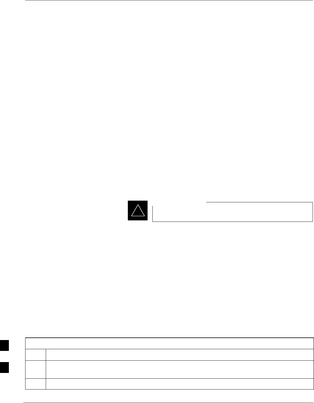
Figure 9-18: SDCX Module
BOTTOM VIEW
Connector
Plug
Expansion SDC
Connectors
RGPS
TAIL
Connector
Used only if the site is
configured for multiple BTSs.
9
SDCX Module – continued
MAY 2004 1X SC480 BTS Hardware Installation, Optimization/ATP, and FRU 9-53
PRELIMINARY
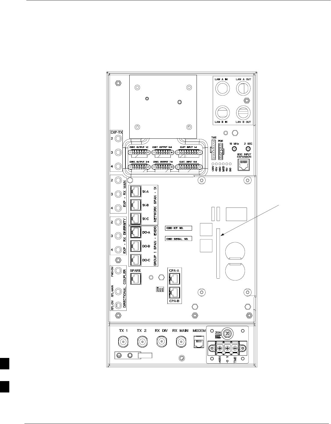
Figure 9-19: CBIO Board with SDCX
13003_001C
Remove
screws
Remove
screws
DAISY–CHAIN SYNC – OUT
SDCX KIT NO.
SDCX SERIAL NO.
DAISY–CHAIN POWER
SDCX POWER
EXPANSION FRAME SYNC – OUT
RF–GPS IN
PWR
9
SDCX Module – continued
9-54 1X SC480 BTS Hardware Installation, Optimization/ATP, and FRU MAY 2004
PRELIMINARY
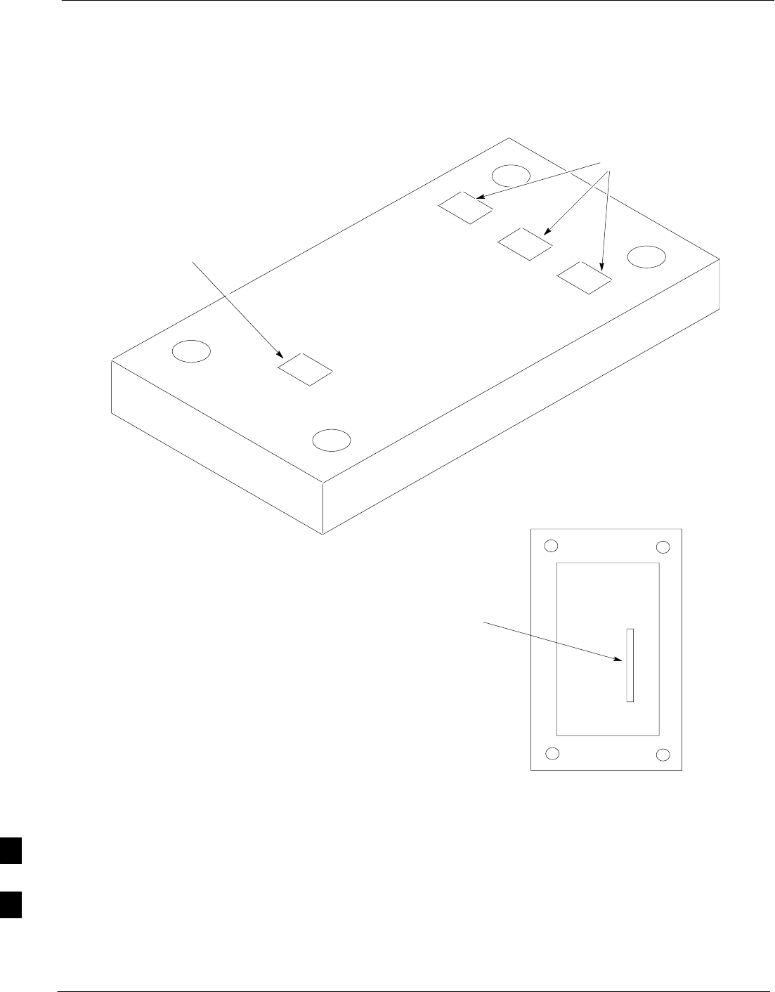
Figure 9-20: CBIO Board with SDCX Removed
SDCX Board
connector
ti–cdma–wp–00311–v01–ildoc–ah
RF–GPD IN
PWR
9
RF Filter Tray
MAY 2004 1X SC480 BTS Hardware Installation, Optimization/ATP, and FRU 9-55
PRELIMINARY
Introduction
The procedures in this section cover only the removal and installation of
the RF Filter Tray.
System Impact/Considerations
If either of the filters on the tray is failing or has failed there will be an
interruption in call processing. The entire site will be down for
replacement of this component.
Required Items
Documents
None
Tools
Screwdriver with T20 star bit
Replacement Items
S800 MHz Filter Kit – 0 cCLPA (SGLF4152)
S800 MHz Filter Kit – 1 cCLPA (SGLN6223)
S800 MHz Filter Kit – 2 cCLPA (SGLN6222)
Prerequisite
Coordinate this repair task with the OMC–R operator.
IMPORTANT
*
Contact the OMC–R operator before performing the replacement
procedure. Tell the operator that the Filter Tray will be replaced and that
alarms can be expected.
Upon completion of the replacement procedure, have the OMC–R
operator verify that old alarms are cleared and that no new ones are
reported.
Replacement Procedure
If desired, record the BTS and Filter Tray serial number of the failed unit
in Table 9-66 at the end of this chapter.
If the BTS is in an outdoor configuration, perform Table 9-51, Remove
TME. The BTS removal is embedded in the procedure.
Remove Filter Tray
Follow the procedure in Table 9-30 to remove the Filter Tray.
9

RF Filter Tray – continued
9-56 1X SC480 BTS Hardware Installation, Optimization/ATP, and FRU MAY 2004
PRELIMINARY
To perform the following procedure, the BTS must be
removed from the Mounting Plate.
NOTE
Table 9-30: Preparation Procedure for Removing the Filter Tray
Step Action
1Notify operator that the Filter Kit replacement procedure is starting and that alarms can be expected.
2Perform the Site Shutdown procedure in Table 10-2.
3Remove 3 M6 screws and washers securing BTS to Mounting Plate.
n WARNING
By pulling out the circuit breaker, power to the BTS will be interrupted, causing the BTS to go off
line.
4Disengage DC power to the BTS by pulling out the 20 A breaker at the rear of the BTS.
5If possible, turn off DC power at the source. Verify that DC Power source is OFF.
6Disconnect all cabling to the BTS.
7Remove BTS from Mounting Plate and place on a stable, flat surface.
8Put on an ESD wrist strap or other approved grounding device.Ensure wrist strap is properly
grounded. Do not ground to BTS chassis.
9If not already done, remove BTS front cover panel by grasping finger grooves at the top and bottom
and pulling.
10 Pull out all the circuit cards and modules.
11 If not already done, remove HSO Module cover panel by turning latch, gently pulling it open, and
sliding it out towards the right. The panel has a flange that fits into a slot in the chassis.
12 Reach fingers in along the right side and feel for the clip that holds on the lower front right side vent
panel, and pop out the panel.
13 Using the hole left by the front right side vent panel, reach fingers in along the divider and press on
the clip holding the rear right side vent panel and pop it out.
14 If the BTS is equipped with Filter Tray Kit SGLF4152, proceed to Table 9-31.
If the BTS is equipped with Filter Tray Kit SGLN6223, proceed to Table 9-35.
If the BTS is equipped with Filter Tray Kit SGLN6222, proceed to Table 9-37.
Filter Tray Kit SGLF4152
Removal Procedure
Follow the procedure in Table 9-31 to remove the Filter Tray.
9

RF Filter Tray – continued
MAY 2004 1X SC480 BTS Hardware Installation, Optimization/ATP, and FRU 9-57
PRELIMINARY
Table 9-31: Procedure to Remove Filter Tray Kit SGLF4152
Step Action
1Perform the preparation procedure described in Table 9-30.
2Using a screwdriver with T20 star bit, remove two screws securing the Filter Tray Assembly to the
chassis.
3Disconnect the RF cables (Input) in the following order:
– RX MAIN connector (blue)
RX DIV connector (green)
RX RFL–MAIN connector (blue)
RX RFL–DIV connector (green)
RX FWD–DIV connector (green)
4Hold cables to one side and slide out filter tray to expose cables attached to rear connector (Output) of
each filter.
5Disconnect RX MAIN cable (blue).
6Disconnect RX DIV cable (green).
7Remove Filter Tray completely.
cMPC Cable Clip Removal
Procedure
Follow the procedure in Table 9-32 to remove the cMPC cable clip. The
cMPC cable clip is located just inside the front of the BTS, on the CCP2
shelf on the right side (looking into the BTS).
Table 9-32: Procedure to Remove cMPC Cable Clip
Step Action
NOTE
cMPC cable clip only needs to be removed if filter tray is not replaced with the same type. Clip
removal is to accommodate other filter tray configurations or cable replacement.
1Using a small, flat blade screwdriver, reach in and simultaneously lift tab and push towards the front
of the BTS. See Figure 9-21.
2Using thumb and forefinger grasp tab (narrow end), and pull up and towards rear to pop out clip.
3Remove clip and place a side.
4Remove the RX MAIN (blue) and RX DIV (green) cables.
9
RF Filter Tray – continued
9-58 1X SC480 BTS Hardware Installation, Optimization/ATP, and FRU MAY 2004
PRELIMINARY
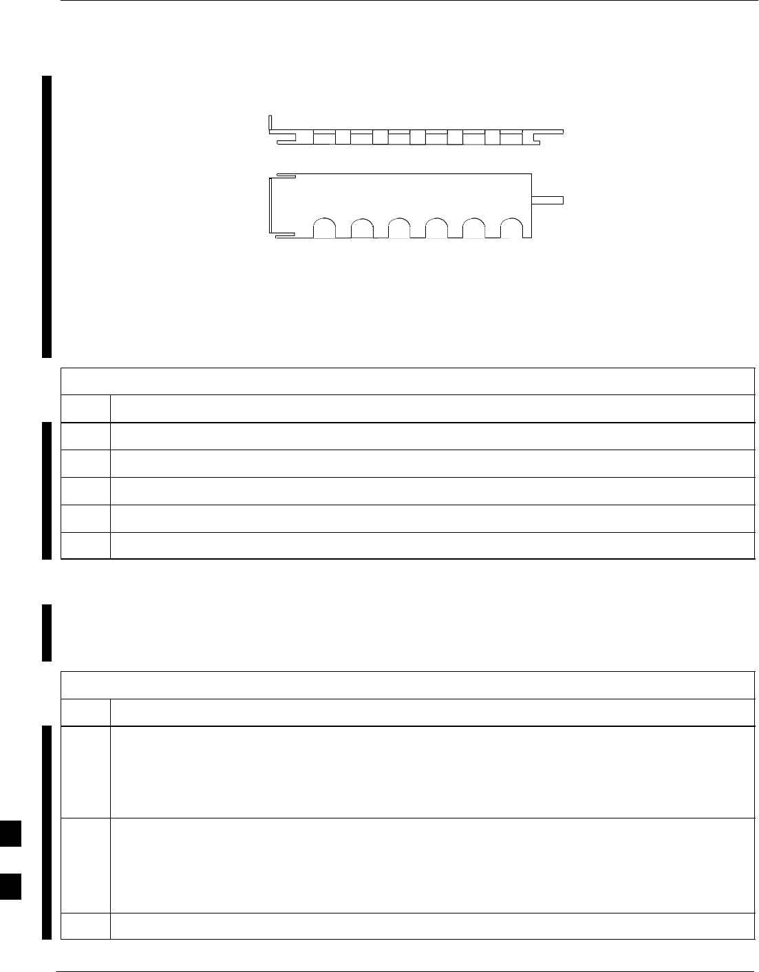
Figure 9-21: cMPC Cable Clip
SLOT1 SLOT6
TOWARDS
FRONT OF BTS
TOWARDS
REAR OF BTS
cMPC Cable Clip Installation
Procedure
Follow the procedure in Table 9-33 to install the cMPC cable clip.
Table 9-33: Procedure to Install cMPC Cable Clip
Step Action
1Properly position cables in clip (order defined in installation procedure).
2Insert clip by sliding in wide flange end in first (towards front of BTS)
3Using a thumb, press on clip and push towards rear, slipping clip into place.
4Route cables inside BTS towards filter tray.
5Return to filter tray installation procedure.
Install Filter Tray Kit SGLF4152
Follow the procedure in Table 9-34 to install the Filter Tray. Refer to
Figure 9-22.
Table 9-34: Procedure to Install Filter Tray Kit SGLF4152
Step Action
1Put on an ESD wrist strap or other approved grounding device. Ensure that wrist strap is properly
grounded.
NOTE
Do not attach ESD wrist strap to BTS chassis.
2If not already installed, the following cables must be installed:
– RX RFL–MAIN (blue)
– RX RFL–DIV (green)
– RX FWD–DIV (green)
3Remove the CBIO Board by performing the procedure described in Table 9-26.
table continued on next page
9

RF Filter Tray – continued
MAY 2004 1X SC480 BTS Hardware Installation, Optimization/ATP, and FRU 9-59
PRELIMINARY
Table 9-34: Procedure to Install Filter Tray Kit SGLF4152
Step Action
4Connect cables to the RFL–MAIN, RFL–DIV, and FWD–DIV connectors at the inside rear of the
BTS, respectively. Use a 5/16–in wrench to secure cables to connectors. Torque to 1 N–M.
NOTE
Cables have two heat shrink sleeves with a slight separation between them. The cMPC cable clip
slides into this separation to hold the cables in place.
5Install RX MAIN and RX DIV cables as follows:
– Ensuring the cable is on the inside of BTS, place RX DIV (green) cable into slot 1 of cMPC cable
clip (Connector labeled RX DIV faces towards the front of BTS)
– Place RX MAIN (blue) cable into slot 2 of cMPC cable clip (Connector labeled RX MAIN faces
towards the front of BTS).
– Place (red) cable into slot 5.
– Place (black) cable into slot 6.
6Perform Table 9-33 to install the cMPC cable clip. (If it had been removed.)
7Set Filter Tray on the edge of its slot and connect the RX MAIN (blue) and RX DIV (green) cables to
the output connector at the rear of their respective filters. See Figure 9-22.
8Slide Filter Tray into BTS chassis and secure using 2 M4 screws. Torque to 2.3 N–M (20 in–lbs).
9Connect the following cables:
– RX MAIN (blue) to RX MAIN input
– RX DIV (green) to RX DIV input
– RX RFL–MAIN (blue) to RFL–MAIN input
– RX RFL–DIV (green) to RFL–DIV input
– RX FWD–DIV (green) to FWD–DIV input
See Figure 9-22.
10 Use tie–wraps to dress cables as necessary.
11 Install the rear right side vent panel. Ensure that the clip end faces the front of the BTS or towards the
left.
12 Install the front right side vent panel. Ensure that the clip end faces the front of the BTS or towards the
left.
13 Make sure the vent panels are flush with the side of the BTS.
14 Install CBIO Board following the procedure in Table 9-27.
15 Install circuit cards and modules, ensure they are seated properly.
16 Install HSO Module cover panel by sliding its flange into the slot, closing, and latching it in place.
17 Disengage from the ESD wrist strap.
18 Set the BTS on the Mounting Plate and secure using 3 M6 screws and isolation washers. Torque to 5
N–M (44 in–lbs).
table continued on next page
9

RF Filter Tray – continued
9-60 1X SC480 BTS Hardware Installation, Optimization/ATP, and FRU MAY 2004
PRELIMINARY
Table 9-34: Procedure to Install Filter Tray Kit SGLF4152
Step Action
19 Connect all external cabling.
20 Verify that DC power source is OFF before re–connecting to the BTS.
Turn on DC power source.
21 Notify the operator know that the replacement procedure is completed, and that power up will begin
shortly.
22 Allow the BTS to power up by pushing in the 20 A circuit breaker at the rear of the BTS.
23 Perform the Site Startup procedure in Table 10-5.
24 Perform an optimization of the cards, using the procedures in the Optimization/ATP section of this
manual.
25 After BTS is optimized, and it is operating within normal parameters, install the BTS front cover
panel by setting it in place and pushing on the top and bottom simultaneously.
26 Notify operator that optimization is complete.
9
RF Filter Tray – continued
MAY 2004 1X SC480 BTS Hardware Installation, Optimization/ATP, and FRU 9-61
PRELIMINARY
Figure 9-22: Filter Tray Connectors and Cable Part Numbers
RX DIV
Cable PN 3086617X05
RFL–MAIN
Cable PN
3086617X07
RX MAIN
Cable PN
3086617X04
FWD–DIV
Cable PN
3086617X18
RFL–DIV
Cable PN 3086617X08
Front View
Input Connectors
Rear View
Output Connectors
RX DIV
Cable PN 3086617X02 RX MAIN
Cable PN 3086617X03
Filter Tray Kit SGLN6223
Removal Procedure
Follow the procedure in Table 9-35 to remove the Filter Tray Kit
(SGLN6223).
Table 9-35: Procedure to Remove Filter Tray Kit SGLN6223
Step Action
1Perform the preparation procedure described in Table 9-30.
2Using a screwdriver with T20 star bit, remove two screws securing the Filter Tray Assembly to the
chassis.
table continued on next page
9
RF Filter Tray – continued
9-62 1X SC480 BTS Hardware Installation, Optimization/ATP, and FRU MAY 2004
PRELIMINARY
Table 9-35: Procedure to Remove Filter Tray Kit SGLN6223
Step Action
3Disconnect the RF cables (Input) in the following order:
– RX MAIN connector (blue) from RX MAIN connector
RX DIV connector (green)
RX RFL–DIV connector (green)
RX FWD–DIV connector (green)
See Figure 9-23
4Hold cables to one side and slide out filter tray to expose cable attached to rear connector (Output) of
the RX DIV filter.
5Disconnect RX DIV (Output) cable (green).
6Remove Filter Tray completely.
Figure 9-23: Filter Tray Connectors and Cable Part Numbers (SGLN6223)
RX DIV
Cable PN 3086617X05
RX MAIN
(from input)
Cable PN
3086617X35 FWD–DIV
Cable PN
3086617X18
RFL–DIV
Cable PN 3086617X08
Front View
Input Connectors
RX MAIN
(from output)
Cable PN
3086617X04
RX DIV
Cable PN 3086617X02
Rear View
Output Connector
9

RF Filter Tray – continued
MAY 2004 1X SC480 BTS Hardware Installation, Optimization/ATP, and FRU 9-63
PRELIMINARY
Install Filter Tray Kit SGLN6223
Follow the procedure in Table 9-36 to install the Filter Tray. Refer to
Figure 9-22.
Table 9-36: Procedure to Install Filter Tray Kit SGLN6223
Step Action
1Put on an ESD wrist strap or other approved grounding device. Ensure that wrist strap is properly
grounded.
NOTE
Do not attach grounding devices to BTS chassis.
2If the filter tray to be installed is different from the one removed, proceed to the appropriate filter tray
installation procedure. Otherwise, proceed to step 5.
3If not already installed, the following cables must be installed:
– RX RFL–DIV (green)
– RX FWD–DIV (green)
4Remove the CBIO Board by performing the procedure described in Table 9-26.
5Connect cables to the RFL–DIV and FWD–DIV connectors, respectively. Use a 5/16–in wrench to
secure cables to connectors. Torque to 1 N–M.
NOTE
Cables have two heat shrink sleeves with a slight separation between them. The cMPC cable clip
slides into this separation to hold the cables in place.
6Install RX MAIN and RX DIV cables as follows:
– Ensuring the cable is on the inside of BTS, place RX DIV (green) cable into slot 1 of cMPCcable
clip (Connector labeled RX DIV faces towards the front of BTS)
– Place RX MAIN (blue) cable into slot 2 of cMPC cable clip (Connector labeled RX MAIN faces
towards the front of BTS).
– Place (red) cable into slot 5.
– Place (black) cable into slot 6.
7Perform Table 9-33 to install the cMPC cable clip.
8Set new Filter Tray into its slot and connect the input RX MAIN (blue) directly to output RX MAIN
cable. Connect RX DIV (green) cable to the output connector at the rear of the RX DIV filter. See .
9Slide Filter Tray into BTS chassis and secure using 2 M4 screws. Torque to 2.3 N–M (20 in–lbs).
10 Connect the following cables:
– RX DIV (green) to RX DIV input
– RX RFL–DIV (green) to RFL–DIV input
– RX FWD–DIV (green) to FWD–DIV input
See Figure 9-23.
11 Use tie–wraps to dress cables as necessary.
table continued on next page
9

RF Filter Tray – continued
9-64 1X SC480 BTS Hardware Installation, Optimization/ATP, and FRU MAY 2004
PRELIMINARY
Table 9-36: Procedure to Install Filter Tray Kit SGLN6223
Step Action
12 Install the rear right side vent panel. Ensure that the clip end faces the front of the BTS or towards the
left.
13 Install the front right side vent panel. Ensure that the clip end faces the front of the BTS or towards the
left.
14 Make sure the vent panels are flush with the side of the BTS.
15 Install CBIO Board following the procedure in Table 9-27.
16 Install circuit cards and modules, ensure they are seated properly.
17 Install HSO Module cover panel by sliding its flange into the slot, closing, and latching it in place.
18 Disengage from the ESD wrist strap.
19 Set the BTS on the Mounting Plate and secure using 3 M6 screws and isolation washers. Torque to 5
N–M (44 in–lbs).
20 Connect all external cabling.
21 Verify that DC power source is OFF before re–connecting to the BTS.
Turn on DC power source.
22 Notify the operator know that the replacement procedure is completed, and that power up will begin
shortly.
23 Allow the BTS to power up by pushing in the 20 A circuit breaker at the rear of the BTS.
24 Perform the Site Startup procedure in Table 10-5.
25 Perform an optimization of the cards, using the procedures in the Optimization/ATP section of this
manual.
26 After BTS is optimized, and it is operating within normal parameters, install the BTS front cover
panel by setting it in place and pushing on the top and bottom simultaneously.
27 Notify operator that optimization is complete.
Filter Tray Kit SGLN6222
Removal Procedure
Follow the procedure in Table 9-37 to remove the Filter Tray Kit
(SGLN6222).
9

RF Filter Tray – continued
MAY 2004 1X SC480 BTS Hardware Installation, Optimization/ATP, and FRU 9-65
PRELIMINARY
Table 9-37: Procedure to Remove Filter Tray Kit SGLN6222
Step Action
1Perform the preparation procedure described in Table 9-30.
2Disconnect the cables in the following order:
– RX MAIN connector (X35, blue) from RX MAIN (X04, blue) connector
RX DIV connector (X36, green) from RX DIV (X05, green) connector
See Figure 9-24.
3Remove cMPC cable clip per Table 9-32, if necessary
Install Filter Tray Kit SGLN6222
Follow the procedure in Table 9-38 to install the Filter Tray.
Table 9-38: Procedure to Install Filter Tray Kit SGLN6222
Step Action
1Put on an ESD wrist strap or other approved grounding device. Ensure that wrist strap is properly
grounded.
NOTE
Do not attach ESD wrist strap to BTS chassis.
2If the filter tray to be installed is different from the one removed, proceed to the appropriate filter tray
installation procedure. Otherwise, proceed to step 5.
NOTE
Cables have two heat shrink sleeves with a slight separation between them. The cMPC cable clip
slides into this separation to hold the cables in place.
3Install RX MAIN and RX DIV cables as follows:
– Ensuring the cable is on the inside of BTS, place RX DIV (green) cable into slot 1 of cMPC cable
clip (Connector labeled RX DIV faces towards the front of BTS)
– Place RX MAIN (blue) cable into slot 2 of cMPC cable clip (Connector labeled RX MAIN faces
towards the front of BTS).
– Place (red) cable into slot 5.
– Place (black) cable into slot 6.
See Figure 9-24.
4Perform Table 9-33 to install the cMPC cable clip. (If it had been removed.)
5Connect the input RX MAIN (blue) directly to output RX MAIN cable. Connect input RX DIV
(green) directly to the output RX DIV cable
6Use tie–wraps to dress cables as necessary.
7Install the rear right side vent panel. Ensure that the clip end faces the front of the BTS or towards the
left.
table continued on next page
9

RF Filter Tray – continued
9-66 1X SC480 BTS Hardware Installation, Optimization/ATP, and FRU MAY 2004
PRELIMINARY
Table 9-38: Procedure to Install Filter Tray Kit SGLN6222
Step Action
8Install the front right side vent panel. Ensure that the clip end faces the front of the BTS or towards the
left.
9Make sure the vent panels are flush with the side of the BTS.
10 Install circuit cards and modules, ensure they are seated properly.
11 Install HSO Module cover panel by sliding its flange into the slot, closing, and latching it in place.
12 Disengage from the ESD wrist strap.
13 Set the BTS on the Mounting Plate and secure using 3 M6 screws and isolation washers. Torque to
5 N–M (44 in–lbs).
14 Connect all external cabling.
15 Verify that DC power source is OFF before re–connecting to the BTS.
Turn on DC power source.
16 Notify the operator know that the replacement procedure is completed, and that power up will begin
shortly.
17 Allow the BTS to power up by pushing in the 20 A circuit breaker at the rear of the BTS.
18 Perform the Site Startup procedure in Table 10-5.
19 Perform an optimization of the cards, using the procedures in the Optimization/ATP section of this
manual.
20 After BTS is optimized, and it is operating within normal parameters, install the BTS front cover
panel by setting it in place and pushing on the top and bottom simultaneously.
21 Notify operator that optimization is complete.
Figure 9-24: Filter Tray Connectors and Cable Part Numbers (SGLN6222)
RX MAIN (from input)
Cable PN 3086617X35
Front View
Input Connectors
RX MAIN (from output)
Cable PN 3086617X04 RX DIV (from input)
Cable PN 3086617X36
RX DIV (from output)
Cable PN 3086617X05
9
Compact Combined Linear Power Amplifier
MAY 2004 1X SC480 BTS Hardware Installation, Optimization/ATP, and FRU 9-67
PRELIMINARY
Introduction
The procedures in this section cover only the removal and installation of
the Compact Combined Linear Power Amplifier (cCLPA).
System Impact/Considerations
If the cCLPA is failing or has failed there will be an interruption in call
processing. While the BTS itself may be operational, there may not be
reception or transmission depending on the fault.
Required Items
Documents
None
Tools
Screwdriver with T20 star bit
Replacement Item
S –48 VDC A Band (STTF4023)
S+27 VDC A Band (STTF4024)
S+27 VDC B Band (STTF4025)
Prerequisite
Coordinate this repair task with the OMC–R operator.
IMPORTANT
*
Contact the OMC–R operator before performing the replacement
procedure. Tell the operator that the Filter Tray will be replaced and that
alarms can be expected.
Upon completion of the replacement procedure, have the OMC–R
operator verify that old alarms are cleared and that no new ones are
reported.
Replacement Procedure
If desired, record the BTS and cCLPA serial number of the failed unit in
Table 9-67 at the end of this chapter.
Remove cCLPA
Follow the procedure in Table 9-39 to remove the cCLPA.
Table 9-39: Procedure to Remove cCLPA
Step Action
1Notify operator that the cCLPA replacement procedure is starting and that alarms can be expected.
2Have OMC–R operator disable the cCLPA and the associated BBX card(s).
table continued on next page
9

Compact Combined Linear Power Amplifier – continued
9-68 1X SC480 BTS Hardware Installation, Optimization/ATP, and FRU MAY 2004
PRELIMINARY
Table 9-39: Procedure to Remove cCLPA
Step Action
3Turn off DC power to the cCLPA. For Outdoor configuration disengage the PDE circuit breaker to the
cCLPA being removed.
4Use a screwdriver with a T20 star bit to remove 8 screws securing I/O Board cover to the cCLPA.
5Loosen screws securing DC power to the I/O Board DC connector.
6Disconnect BTS Data Cable from the I/O Board.
7Disconnect ground cable from the cCLPA.
8Remove 4 M6 screws securing cCLPA to the rack.
9Loosen 2 M6 screws securing cCLPA flange to the rack enough to safely remove the cCLPA.
10 Lift cCLPA up and away from the rack.
Install cCLPA
Follow the procedure in Table 9-40 to install the cCLPA.
Table 9-40: Procedure to Install cCLPA
Step Action
1Lift cCLPA up and hang on two screws. Ensure that all screw holes align, then tighten screws to
flange.
2Install 4 M6 screws and secure cCLPA to rack.
3Connect ground cable to cCLPA.
4Route BTS Data Cable through cCLPA DATA opening and connect to RJ45 connector on cCLPA I/O
Board.
5Route DC power cable through DC IN opening and insert in DC Power terminal board. Ensure that the
“–” wire goes to –48V and the “+” wire goes to 0V locations. Tighten the screws to secure the wires in
place.
6Install I/O Board cover panel and use a screwdriver with a T20 star bit to secure it to cCLPA using 8
M6 screws.
7On cCLPA, pull out 20A circut breaker.
8Turn on cCLPA DC power source.
9Allow the cCLPA to power up by pushing in the 20 A circuit breaker.
10 Notify OMC–R operator that the cCLPA replacement procedure is completed.
11 Have OMC–R operator enable cCLPA and associated BBX card(s) that were taken out–of–service and
verify that there are no new alarms.
9
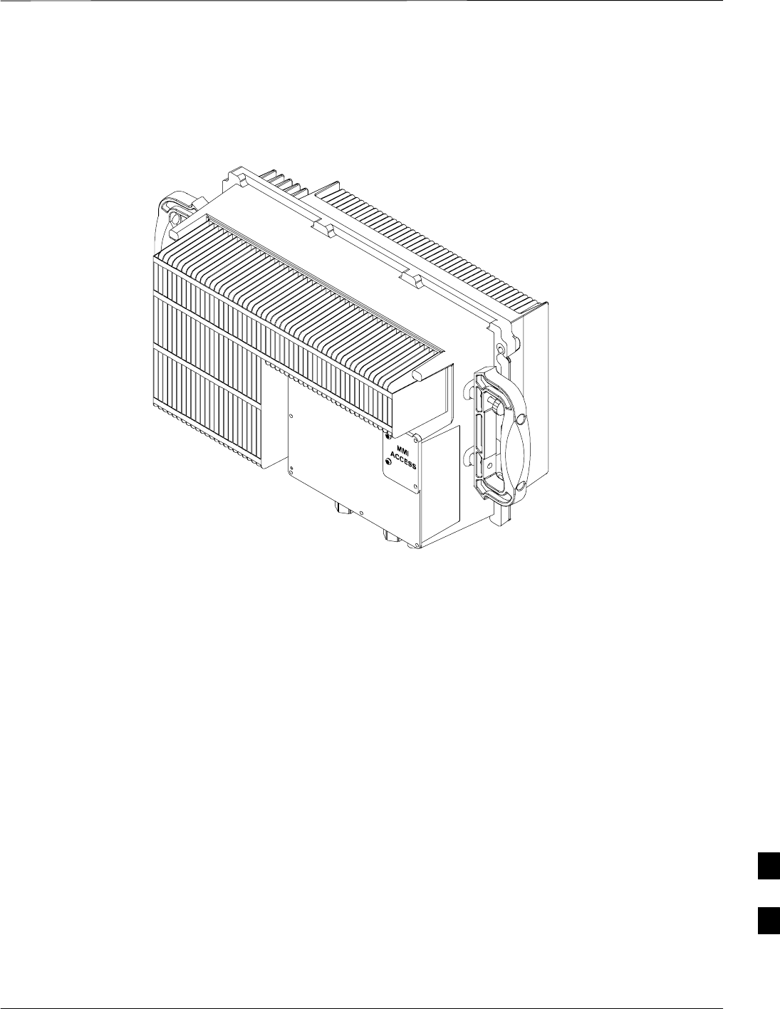
Compact Combined Linear Power Amplifier – continued
MAY 2004 1X SC480 BTS Hardware Installation, Optimization/ATP, and FRU 9-69
PRELIMINARY
Figure 9-25: Compact Combined Linear Power Amplifier
ti–cdma–wp–00300–v01–ildoc–ah
9
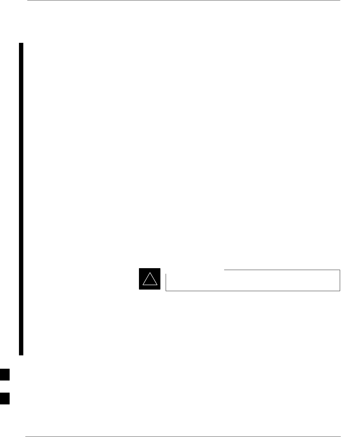
TME Power Distribution Assembly
9-70 1X SC480 BTS Hardware Installation, Optimization/ATP, and FRU MAY 2004
PRELIMINARY
Introduction
The procedures in this section cover only the removal and installation of
the TME Power Distribution Assembly (PDA)
System Impact/Considerations
If the PDA is failing or has failed there will be an interruption in call
processing. Power to the BTS and 1U unit will be interrupted.
Required Items
Documents
None
Tools
SScrewdriver with T20 star bit
STorque Driver Wrench or Torque Ratchet Wrench
SSocket, 8 mm, 3/8–in or 1/4–in
SFlat head or Phillips head screw driver
Replacement Item
SPDA (STHN4066A)
Prerequisite
Coordinate this repair task with the OMC–R operator.
IMPORTANT
*
Contact the OMC–R operator before performing the replacement
procedure. Tell the operator that the PDA will be replaced and that
alarms can be expected.
Upon completion of the replacement procedure, have the OMC–R
operator verify that old alarms are cleared and that no new ones are
reported.
9
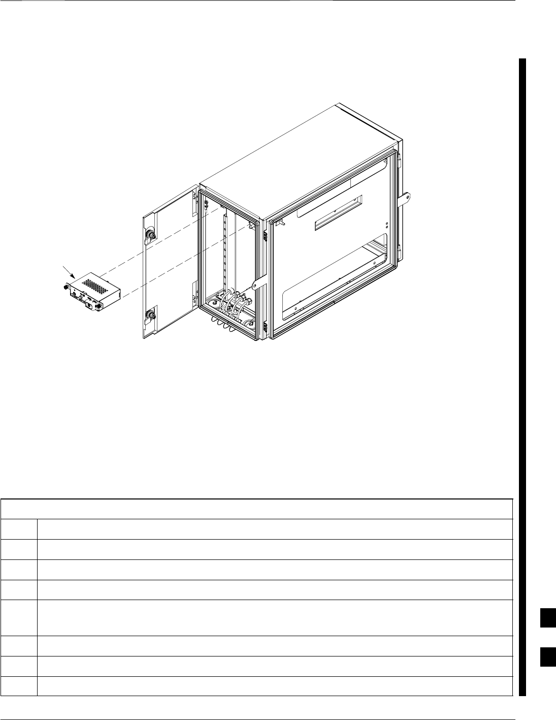
TME Power Distribution Assembly – continued
MAY 2004 1X SC480 BTS Hardware Installation, Optimization/ATP, and FRU 9-71
PRELIMINARY
Figure 9-26: PDA Location
ti–cdma–wp–00262–v03–ildoc–ah
–48VDC PDA
Replacement Procedure
If desired, record the BTS and PDA serial number of the failed unit in
Table 9-68 at the end of this chapter.
Remove PDA
Follow the procedure in Table 9-41 to remove the PDA. See Figure 9-26
or Figure 9-28.
Table 9-41: Procedure to Remove PDA
Step Action
1Notify operator that the PDA replacement procedure is starting and that alarms can be expected.
2Disengage circuit breakers by pulling or setting to “O” position.
3Turn off DC power to the PDA.
4On –48VDC PDA, remove protective cap from DC Power connector. Proceed to step 5.
On +27VDC PDA disconnect power plug from connector. Proceed to step 6.
5Use a screwdriver to loosen screws securing DC power wires to PDA.
6Use a wrench to remove two nuts and washers securing ground lug to the PDA.
7Loosen captive screws securing PDA to TME chassis.
table continued on next page
9
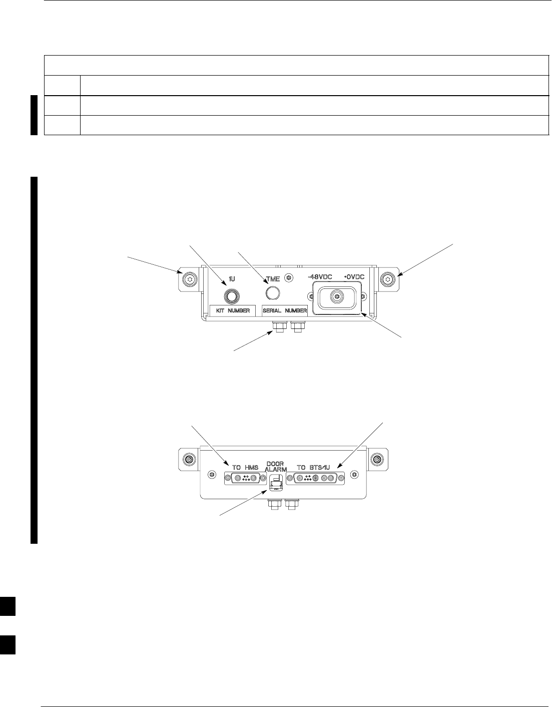
TME Power Distribution Assembly – continued
9-72 1X SC480 BTS Hardware Installation, Optimization/ATP, and FRU MAY 2004
PRELIMINARY
Table 9-41: Procedure to Remove PDA
Step Action
8Gently pull out PDA far enough to disconnect cables at the rear.
9Remove PDA.
Figure 9-27: Power Distribution Assembly for –48VDC
Captive
Screw
Captive
Screw
FRONT
ti–cdma–wp–00348–v01–ildoc–ah
ti–cdma–wp–00346–v01–ildoc–ah
REAR
Ground
Location
1U
Circuit
Breaker
TME
Circuit
Breaker
DC Power
Connection (under
protective cap)
TME Door
Alarm
Connection
BTS / 1U
Connection
HMS
Connection
9

TME Power Distribution Assembly – continued
MAY 2004 1X SC480 BTS Hardware Installation, Optimization/ATP, and FRU 9-73
PRELIMINARY
Install PDA
Follow the procedure in Table 9-42 to install the PDA. See Figure 9-26
or Figure 9-28.
Table 9-42: Procedure to Install PDA
Step Action
1Hold PDA near its slot in the TME and connect the cables (previously disconnected) to the rear of the
PDA.
2Slide PDA in and secure to TME chassis by tightening the captive screws.
3Place ground lug on ground studs of the PDA and secure using two M6 nuts and washers. Torque nuts
to 3.4 N–M (30 in–lbs).
4Verify that circuit breakers are disengaged (pulled out or set to “O” position).
5Verify that DC power source is OFF.
6For –48 VDC PDA, connect DC power to the PDA using a screwdriver to tighten screws. Proceed to
step 7.
For +27 VDC PDA, connect power plug . Proceed to step 8.
7Install DC power protective cap.
8Turn on DC power.
9On –48 VDC PDA, push in TME circuit breaker.
On +27VDC PDA, set switch to “1” position.
10 Push in 1U circuit breaker.
11 Notify operator that replacement is complete and verify that no new alarms have been generated and
that old alarms are cleared.
9
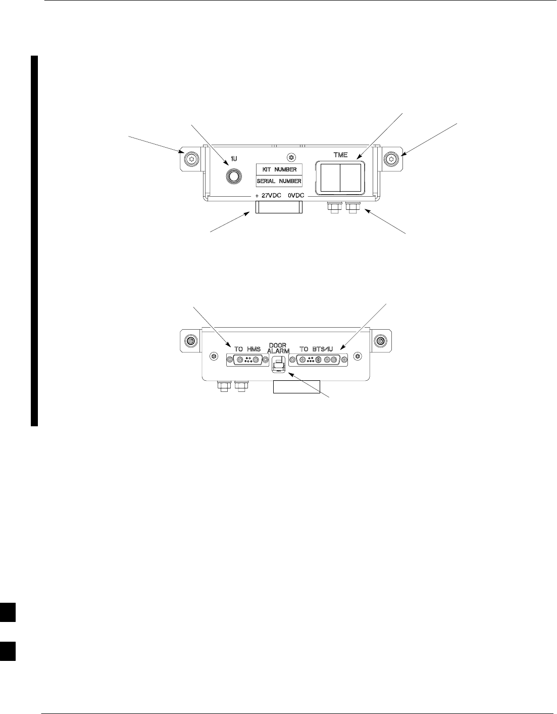
TME Power Distribution Assembly – continued
9-74 1X SC480 BTS Hardware Installation, Optimization/ATP, and FRU MAY 2004
PRELIMINARY
Figure 9-28: Power Distribution Assembly for +27VDC
Captive
Screw
Captive
Screw
FRONT
ti–cdma–wp–00348–v01–ildoc–ah
ti–cdma–wp–00346–v01–ildoc–ah
REAR
Ground
Location
1U
Circuit
Breaker
TME Circuit
Breaker
(Rocker Style)
TME Door Alarm
Connection
BTS / 1U
Connection
HMS
Connection
+27 VDC
Connector
Socket
9

Heat Management System
MAY 2004 1X SC480 BTS Hardware Installation, Optimization/ATP, and FRU 9-75
PRELIMINARY
Introduction
The procedures in this section cover only the removal and installation of
the Heat Management System (HMS)
System Impact/Considerations
If the HMS is failing or has failed there will be an interruption in call
processing. It is recommended that power be disengaged from the TME.
Required Items
Documents
None
Tools
SScrewdriver with T20 star bit
STorque Driver Wrench or Torque Ratchet Wrench
SSocket, 10 mm, 3/8–in or 1/4–in
Replacement Item
SHMS
SHeater Elements
SBlower Fan
SHMS Controller
Periodic Maintenance
The louvers over the HMS intake fan need to be inspected and cleaned in
order to ensure proper operation of the TME/BTS. A vacuum cleaner or
soft bristle brush is recommended to clean the louvers.
The condition of the louvers must be monitored. The
recommended service interval is every 90 days, barring any
previous inspections. Once environmental conditions at the
site are established by inspection, it is possible that
cleaning intervals may need to be adjusted to more or less
than the nominal 90 day interval.
NOTE
Prerequisite
Coordinate this repair task with the OMC–R operator.
IMPORTANT
*
9
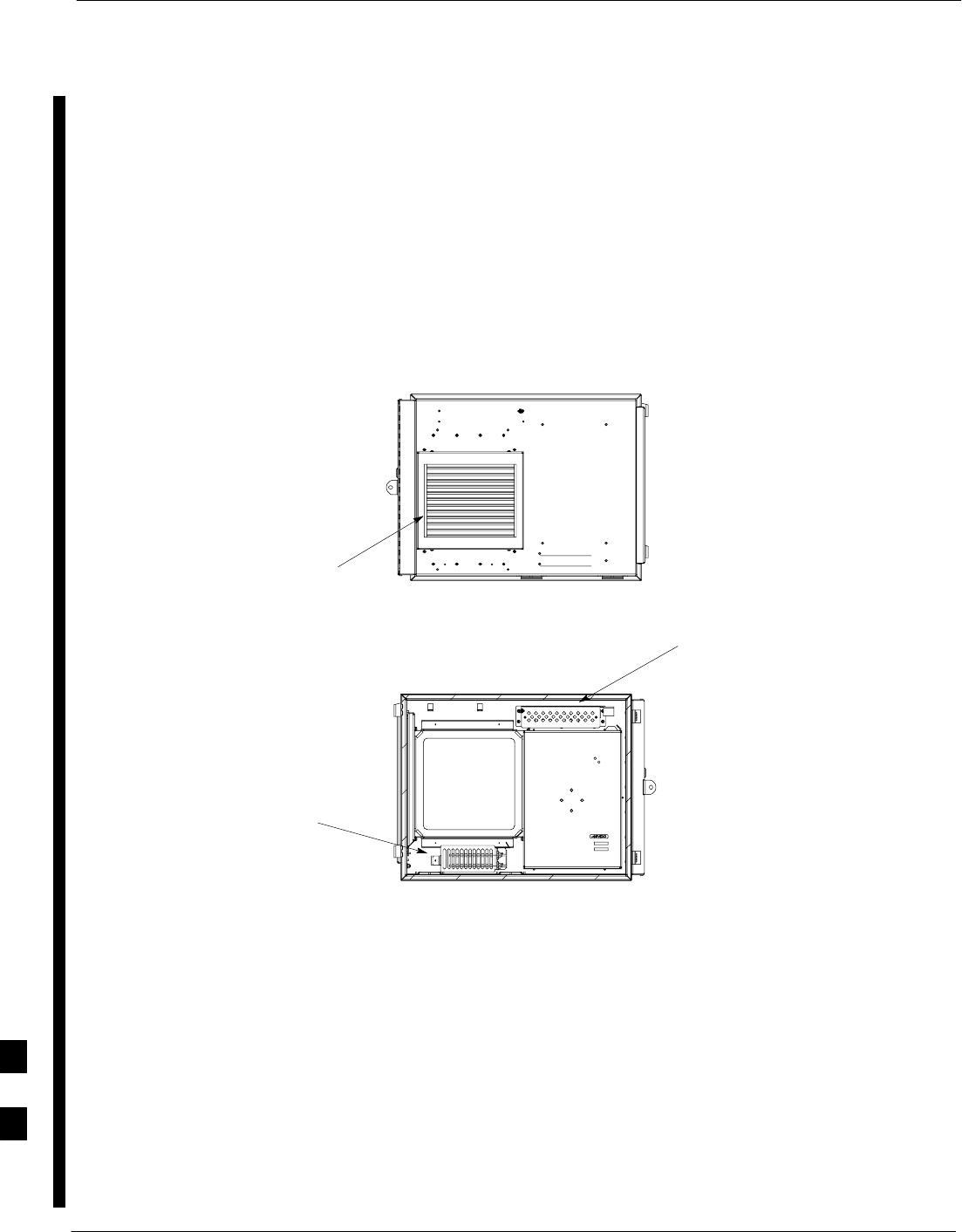
Heat Management System – continued
9-76 1X SC480 BTS Hardware Installation, Optimization/ATP, and FRU MAY 2004
PRELIMINARY
Contact the OMC–R operator before performing the replacement
procedure. Tell the operator that the HMS or its components will be
replaced and that alarms can be expected.
Upon completion of the replacement procedure, have the OMC–R
operator verify that old alarms are cleared and that no new ones are
reported.
Figure 9-29:Heat Management System
ti–cdma–wp–00337–v01–ildoc–ah
Blower
(Behind Louvers)
HMS
Controller
Heater
Elements
Replacement Procedure
If desired, record the TME and HMS serial number of the failed unit in
Table 9-69 at the end of this chapter.
Remove HMS
Follow the procedure in Table 9-43 to remove the HMS. See
Figure 9-29.
9

Heat Management System – continued
MAY 2004 1X SC480 BTS Hardware Installation, Optimization/ATP, and FRU 9-77
PRELIMINARY
Table 9-43: Procedure to Remove HMS
Step Action
1Notify operator that the HMS replacement procedure is starting and that alarms can be expected.
2Turn off DC power to the TME.
3Unlock and remove external lock
4Use key to unlock HMS draw latch door.
5Turn latches and slowly swing open HMS.
! CAUTION
Be aware of the heater elements, they will be hot to the touch if they have been in recent use.
Removing the HMS exposes the interior of the TME to the elements, cover the opening with a
blanket, towel, tarp, card board, or equivalent item.
6Use an driver wrench with socket to remove two M6 nuts and washers securing ground lug to HMS
door. Disconnect DC power and HMS controller cable from HMS Controller.
7Remove HMS and place on a flat surface, preferably a table of bench top.
! CAUTION
Be careful not to damage louvers protecting Blower Fan.
Install HMS
Follow the procedure in Table 9-44 to re–install the HMS.
Table 9-44: Procedure to Re–install HMS
Step Action
1Carefully lift HMS and set on TME hinge pins.
2Place ground lug on ground studs of the HMS and secure using two M6 nuts and washers. Torque nuts
to 3.4 N–M (30 in–lbs).
3Connect DC Power and HMS controller cable to HMS Controller.
4Close HMS be careful not to pinch any of the wiring.
5Close HMS and secure using the two draw latches. Fold draw latch handles down. Verify that HMS is
fully closed and seated.
6Close HMS draw latch door and lock using key.
7Lock HMS with external lock.
8Notify operator that replacement is complete and verify that no new alarms have been generated and
that old alarms are cleared.
9

Heat Management System – continued
9-78 1X SC480 BTS Hardware Installation, Optimization/ATP, and FRU MAY 2004
PRELIMINARY
Heater Element Replacement
Procedure
This information is still under consideration at this time. Updated
information will be supplied at a later date.
If desired, record the TME, HMS, and HMS Heater Elements serial
number of the failed unit in Table 9-70 at the end of this chapter.
Perform the procedure in Table 9-45 to remove the Heater Elements.
Table 9-45: Procedure to Replace Heater Elements
Step Action
1Perform the HMS removal procedure described in Table 9-43.
! CAUTION
Heater Elements could still be hot, use caution when removing them. Recommend that thermal
resistant gloves be worn to remove the heater elements.
2
3
4
5
Heater Element Installation
Procedure
This information is still under consideration at this time. Updated
information will be supplied at a later date.
Perform the procedure in Table 9-46 toinstall the Heater Elements.
Table 9-46: Procedure to Install Heater Elements
Step Action
1
2
3
4
5Perform the procedure in Table 9-44 to install the HMS.
9
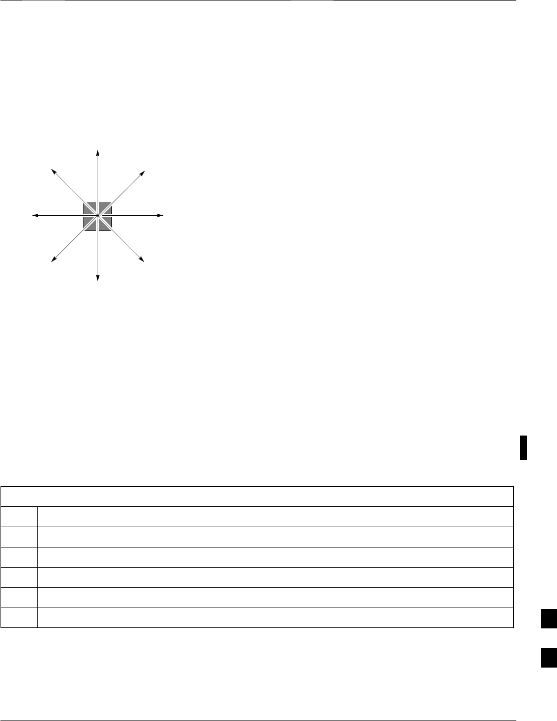
Heat Management System – continued
MAY 2004 1X SC480 BTS Hardware Installation, Optimization/ATP, and FRU 9-79
PRELIMINARY
Figure 9-30: HMS Heater Elements
NOTE:
1. 8 point microdocument
2. 8 point microdocument
8 pt. Left Aligned text
8 pt. Right Aligned Text
8 pt. Centered Text
HMS Controller Replacement
Procedure
This information is still under consideration at this time. Updated
information will be supplied at a later date.
If desired, record the TME, HMS, and HMS Controller serial number of
the failed unit in Table 9-71 at the end of this chapter.
Perform the procedure in Table 9-47 to remove the HMS Controller.
Table 9-47: Procedure to Replace HMS Controller
Step Action
1Perform the HMS removal procedure described in Table 9-43.
2
3
4
5
HMS Controller Installation
Procedure
This information is still under consideration at this time. Updated
information will be supplied at a later date.
9
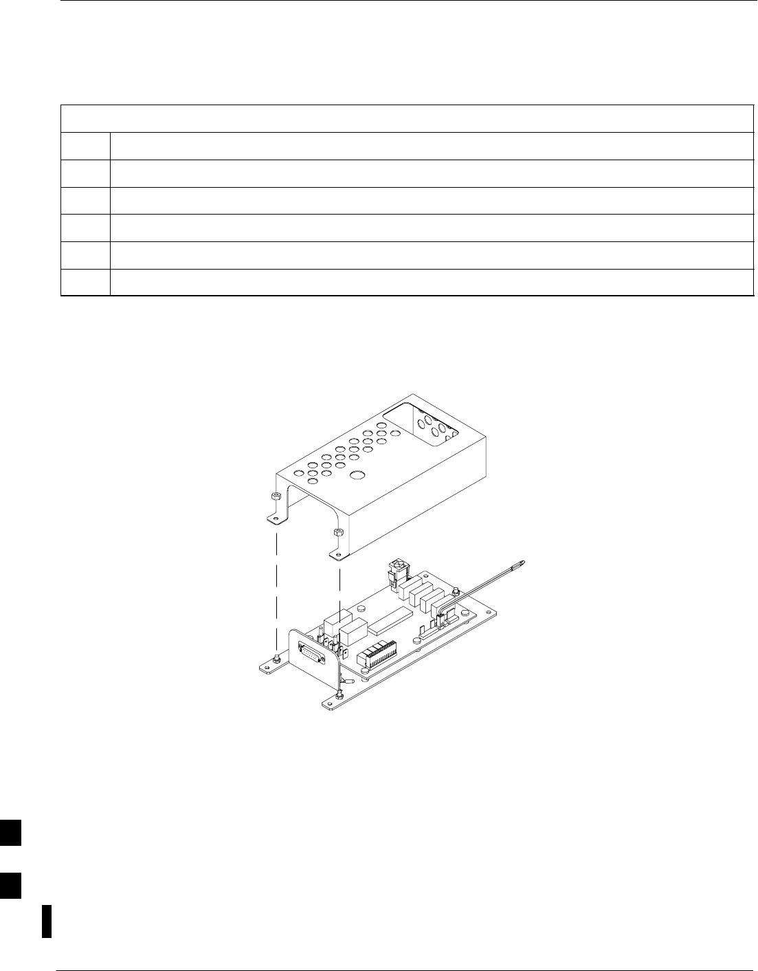
Heat Management System – continued
9-80 1X SC480 BTS Hardware Installation, Optimization/ATP, and FRU MAY 2004
PRELIMINARY
Perform the procedure in Table 9-48 to install the HMS Controller.
Table 9-48: Procedure to Install HMS Controller
Step Action
1
2
3
4
5Perform the procedure in Table 9-44 to install the HMS.
Figure 9-31: HMS Controller
ti–cdma–wp–00263–v01–ildoc–ah
Blower Fan Replacement
Procedure
This information is still under consideration at this time. Updated
information will be supplied at a later date.
If desired, record the TME, HMS, and Blower Fan serial number of the
failed unit in Table 9-72 at the end of this chapter.
Perform the procedure in Table 9-47 to remove the Blower Fan.
9

Heat Management System – continued
MAY 2004 1X SC480 BTS Hardware Installation, Optimization/ATP, and FRU 9-81
PRELIMINARY
Table 9-49: Procedure to Replace Blower Fan
Step Action
1Perform the procedure in Table 9-43 to remove the HMS.
2
3
4
5
Blower Fan Installation
Procedure
This information is still under consideration at this time. Updated
information will be supplied at a later date.
Perform the procedure in Table 9-48 to install the Blower Fan.
Table 9-50: Procedure to Install Blower Fan
Step Action
1
2
3
4
5Perform the procedure in Table 9-44 to install the HMS.
9

Heat Management System – continued
9-82 1X SC480 BTS Hardware Installation, Optimization/ATP, and FRU MAY 2004
PRELIMINARY
Figure 9-32: Blower Fan
NOTE:
1. 8 point microdocument
2. 8 point microdocument
8 pt. Left Aligned text
8 pt. Right Aligned Text
8 pt. Centered Text
9
Thermal Management Enclosure
MAY 2004 1X SC480 BTS Hardware Installation, Optimization/ATP, and FRU 9-83
PRELIMINARY
Introduction
The procedures in this section cover only the removal and installation of
the Thermal Management Enclosure (TME).
System Impact/Considerations
If the TME enclosure has been damaged it will no longer environmetally
protect the BTS. Thus, an interruption in call processingwill occur while
the TME is replaced.
Required Items
Documents
None
Tools
SScrewdriver with T20 star bit or T30 star bit
STorque Driver Wrench or Torque Ratchet Wrench
SSocket, 8 mm, 3/8–in or 1/4–in
S10 mm socket
Replacement Item
STME
Prerequisite
Coordinate this repair task with the OMC–R operator.
IMPORTANT
*
Contact the OMC–R operator before performing the replacement
procedure. Tell the operator that the Filter Tray will be replaced and that
alarms can be expected.
Upon completion of the replacement procedure, have the OMC–R
operator verify that old alarms are cleared and that no new ones are
reported.
Replacement Procedure
Remove TME
Follow the procedure in Table 9-51 to remove the TME.
Table 9-51: Procedure to Remove TME
Step Action
1Notify operator that TME replacement procedure is starting and that alarms can be expected.
2Perform Carrier Shutdown procedure as described in Table 10-4.
table continued on next page
9

Thermal Management Enclosure – continued
9-84 1X SC480 BTS Hardware Installation, Optimization/ATP, and FRU MAY 2004
PRELIMINARY
Table 9-51: Procedure to Remove TME
Step Action
3Disengage circuit breaker on the affected cCLPAs.
4Use the key to unlock both doors of the TME.
5Disengage TME PDA circuit breakers by pulling them out.
6At the rear of the BTS disconnect antenna cables from BTS to TME.
7If not already done, label individual cables as they are disconnected from the rear of the BTS.
8Remove cover and disconnect DC power cables from BTS.
9Use screwdriver to remove two screws securing ground lug to BTS.
10 Use key to unlock the HMS draw latch door.
11 Turn latches and open HMS.
12 Disconnect ground lug by removing two nuts and washers with the driver wrench and socket.
13 Disconnect DC power and HMS controller cable from HMS to TME.
14 Lift HMS off hinge pins on TME and place on a flat surface. See Figure 4-21.
! CAUTION
Be careful not to damage louvers protecting Blower Fan.
15 Remove 5 M6 screws securing BTS to TME. See Figure 4-19.
16 Slide BTS out of TME.
17 Disconnect all conduit hubs and cabling from bottom of TME. Label conduit and cabling as necessary.
18 Remove 6 M6 screws securing TME to Wall Mounting Bracket. See Figure 4-18.
19 Lift TME off of Wall Mounting Bracket.
Install TME
Follow the procedure in Table 9-52 to install the TME.
Table 9-52: Procedure to Install TME
Step Action
1Set the TME onto the Wall Mounting Bracket. Ensure that it rests in the slots of the Wall Mounting
Bracket. See Figure 4-17.
2Secure the TME to the Wall Mounting Bracket using 6 M6 screws. Torque screws to 3.4 N–M (30
in–lbs). See Figure 4-18.
3Place BTS in TME opening and slide it in.
4Secure BTS to TME using 5 M6 screws. Torque screws to 3.4 N–M (30 in–lbs). See Figure 4-19.
table continued on next page
9

Thermal Management Enclosure – continued
MAY 2004 1X SC480 BTS Hardware Installation, Optimization/ATP, and FRU 9-85
PRELIMINARY
Table 9-52: Procedure to Install TME
Step Action
5Insert cables from conduit up through their respective access holes and connect to the BTS.
6Tighten conduit hubs.
7Use a screw driver and two screws to secure the ground lug to the BTS.
8Connect antenna cables from BTS to TME.
9Connect all cabling to connectors on bottom of the TME.
10 Install DC power wires to BTS, use a screwdriver to tighten screws holding wires.
11 Install cover over BTS DC power connection.
12 Set HMS on hinges on TME.
13 Using the driver wrench and socket, attach ground lug to HMS using two nuts and washers.
14 Connect DC power and HMS controller cable.
15 Close HMS and secure using the two draw latches. Fold draw latch handles down. Verify that HMS is
fully closed and seated.
16 Close HMS draw latch door and lock using key.
17 Turn on DC power to TME.
18 Engage PDA circuit breakers (push in).
19 Engage circuit breaker on affected cCLPAs.
20 Notify operator that replacement is complete and verify that no new alarms have been generated and
that old alarms are cleared.
21 Perform Carrier Startup Procedure as described in Table 10-7.
9

Power Distribution Enclosure
9-86 1X SC480 BTS Hardware Installation, Optimization/ATP, and FRU MAY 2004
PRELIMINARY
Introduction
The procedures in this section cover only the removal and installation of
the Powerl Distribution Enclosure (PDE).
System Impact/Considerations
If the PDE enclosure has been damaged it will no longer environmetally
protect the AC–to–DC power converter circuitry. Thus, an interruption
in call processing will occur while the PDE is replaced.
Replacement Procedure
Consult the manufacturer’s Field Replacement Unit (FRU) guide for
removal and replacement information.
9

Master Item Number Failure List
MAY 2004 1X SC480 BTS Hardware Installation, Optimization/ATP, and FRU 9-87
PRELIMINARY
Introduction
The Master Item Number Failure List is provided as a means of keeping
a written record of the units that failed for any particular BTS or BTSes.
The list is for logistical purposes only.
For the BTS Fan Module, use Table 9-53.
Table 9-53: Fan Module Item Number List
Item Number
BTS Number
Fan Module Number
For the HSO/MSO Module, use Table 9-54.
Table 9-54: HSO or MSO Module Item Number List
Item Number
BTS Number
HSO Module Number
MSO Module Number
For the RGPS Head, use Table 9-55.
Table 9-55: RGPS Item Number List
Item Number
BTS Number
RGPS Head Number
For the RF GPS Module, use Table 9-56.
Table 9-56: RF GPS Module Item Number List
Item Number
BTS Number
RF GPS Number
9

Master Item Number Failure List – continued
9-88 1X SC480 BTS Hardware Installation, Optimization/ATP, and FRU MAY 2004
PRELIMINARY
For the PSM, use Table 9-57.
Table 9-57: PSM Item Number List
Item Number
BTS Number
PSM Number
For the CSA Card, use Table 9-58.
Table 9-58: CSA Card Item Number List
Item Number
BTS Number
CSA Card
For the GLI3 Card, use Table 9-59.
Table 9-59: GLI3 Card Item Number List
Item Number
BTS Number
GLI3 Card
For the MCC–1X, use Table 9-60.
Table 9-60: MCC–1X Card Item Number List
Item Number
BTS Number
MCC 1
MCC 2
MCC 3
9

Master Item Number Failure List – continued
MAY 2004 1X SC480 BTS Hardware Installation, Optimization/ATP, and FRU 9-89
PRELIMINARY
For the BBX–1X, use Table 9-61.
Table 9-61: BBX–1X Card Item Number List
Item Number
BTS Number
BBX 1 (SGLF4136)
BBX 4 (SGLF4136)
For the cMPC, use Table 9-62.
Table 9-62: Compact MPC Item Number List
Item Number
BTS Number
Compact MPC Number
For the MCC–DO card, use Table 9-63.
Table 9-63: MCC–DO Card Item Number List
Item Number
BTS Number
MCC–Data Only Card
For the CBIO Board, use Table 9-64.
Table 9-64: CBIO Board Item Number List
Item Number
BTS Number
CBIO Board
For the SDCX Module, use Table 9-65.
Table 9-65: SDCX Module Item Number List
Item Number
BTS Number
SDCX Number
9

Master Item Number Failure List – continued
9-90 1X SC480 BTS Hardware Installation, Optimization/ATP, and FRU MAY 2004
PRELIMINARY
For the Filter Tray, use Table 9-66.
Table 9-66: Filter Tray Kit Item Number List
Item Number
BTS Number
Filter Tray Kit (SGLF4152)
Filter Tray Kit (SGLN6223)
Filter Tray Kit (SGLN6222)
For the cCLPA, use Table 9-67.
Table 9-67: cCLPA Item Number List
Item Number
BTS Number
cCLPA #1 (If used)
cCLPA #2 (If used)
For the TME PDA, use Table 9-68.
Table 9-68: TME PDA Item Number List
Item Number
TME Number
PDA
For the TME HMS, use Table 9-69.
Table 9-69: TME HMS Item Number List
Item Number
TME Number
HMS Number
9

Master Item Number Failure List – continued
MAY 2004 1X SC480 BTS Hardware Installation, Optimization/ATP, and FRU 9-91
PRELIMINARY
For the TME HMS Heater Elements, use Table 9-70.
Table 9-70: TME HMS Heater Element Item Number List
Item Number
TME Number
HMS Number
Heater Element
For the TME HMS Controller, use Table 9-71.
Table 9-71: TME HMS Controller Item Number List
Item Number
TME Number
HMS Number
HMS Controller Number
For the TME HMS Blower Fan, use Table 9-72.
Table 9-72: TME HMS Blower Fan Item Number List
Item Number
TME Number
HMS Number
HMS Blower Fan Number
9

Master Item Number Failure List – continued
9-92 1X SC480 BTS Hardware Installation, Optimization/ATP, and FRU MAY 2004
PRELIMINARY
Notes
9

MAY 2004 1X SC480 BTS Hardware Installation, Optimization/ATP, and FRU
PRELIMINARY
Chapter 10: Reference Procedures Performed At OMC–R
Table of Contents
Reference Procedures Performed At OMC–R 10-1 . . . . . . . . . . . . . . . . . . . . . . . . . .
Introduction 10-1 . . . . . . . . . . . . . . . . . . . . . . . . . . . . . . . . . . . . . . . . . . . . . .
Accessing OMC–R CLI Window 10-2 . . . . . . . . . . . . . . . . . . . . . . . . . . . . . . . . . . . .
Accessing OMC–R CLI Window 10-2 . . . . . . . . . . . . . . . . . . . . . . . . . . . . .
Circuit BTS Shut Down Procedures 10-3 . . . . . . . . . . . . . . . . . . . . . . . . . . . . . . . . . .
Shut Down Site Signaling Functions for a Circuit BTS 10-3 . . . . . . . . . . . .
Shut Down Sector Signaling Functions for a Circuit BTS 10-9 . . . . . . . . . .
Shut Down Carrier Signaling Functions for a Circuit BTS 10-16 . . . . . . . . . .
Circuit BTS Start–Up Procedures 10-23 . . . . . . . . . . . . . . . . . . . . . . . . . . . . . . . . . . . .
Restore Site Signaling Operations for a Circuit BTS 10-23 . . . . . . . . . . . . . .
Restore Sector Signaling Operations for a Circuit BTS 10-26 . . . . . . . . . . . .
Restore Carrier Signaling Operations for a Circuit BTS 10-29 . . . . . . . . . . . .
Packet BTS Shut Down Procedures 10-32 . . . . . . . . . . . . . . . . . . . . . . . . . . . . . . . . . .
Shut Down Site Signaling Functions for a Packet BTS 10-32 . . . . . . . . . . . .
Shut Down Sector Signaling Functions for a Packet BTS 10-39 . . . . . . . . . .
Shut Down Carrier Signaling Functions for a Packet BTS 10-46 . . . . . . . . . .
Packet BTS Start–Up Procedures 10-53 . . . . . . . . . . . . . . . . . . . . . . . . . . . . . . . . . . . .
Restore Site Signaling Operations for a Packet BTS 10-53 . . . . . . . . . . . . . .
Restore Sector Signaling Operations for a Packet BTS 10-56 . . . . . . . . . . . .
Restore Carrier Signaling Operations for a Packet BTS 10-59 . . . . . . . . . . . .
10

Table of Contents – continued
1X SC480 BTS Hardware Installation, Optimization/ATP, and FRU MAY 2004
PRELIMINARY
Notes
10

Reference Procedures Performed At OMC–R
MAY 2004 1X SC480 BTS Hardware Installation, Optimization/ATP, and FRU 10-1
PRELIMINARY
Introduction
The procedures in this chapter are referenced during various FRU
replacement procedures and are performed by the OMC–R operator.
These reference procedure covers the following:
SAccessing OMCR CLI window
SCircuit BTS shut down and restore procedures for:
– BTS
– Sector
– Carrier
SPacket BTS shut down and restore procedures for:
– BTS
– Sector
– Carrier
10
Accessing OMC–R CLI Window
10-2 1X SC480 BTS Hardware Installation, Optimization/ATP, and FRU MAY 2004
PRELIMINARY
Accessing OMC–R CLI Window
Many of the FRU procedures require the OMC–R operator to manipulate
BTS logical devices. This is achieved via UNO or the OMC–R
(Operations and Maintenance Center – Radio) Command Line Interface
(CLI).
The operator enters commands via UNO or OMC–R CLI.
Should there be any issues which affect UNO or the
OMC–R CLI operations, command dependent replacement
procedures cannot be performed.
IMPORTANT
*
OMC–R CLI access procedure
The following procedure is performed by the OMC–R operator at the
OMC–R terminal.
Table 10-1: Login and Access Alarm Window Procedure
nStep Action
1Login by entering the user name.
2Enter the password at the system prompt.
3Open an UNO Alarm Manager window and an OMC–R CLI window from the pull down menu
using the mouse button.
4Verify that the filter display is set to the BTS–# where the work is being performed. This ensures
that any BTS–# alarms, encountered while installing the hardware, can be observed and rectified.
10
Circuit BTS Shut Down Procedures
MAY 2004 1X SC480 BTS Hardware Installation, Optimization/ATP, and FRU 10-3
PRELIMINARY
Shut Down Site Signaling Functions for
a Circuit BTS
If a complete site shutdown is required for the FRU replacement, follow
the procedure in Table 10-2 to disable the circuit BTS site.
This site shut down procedure takes a BTS out–of–service
(OOS), but does not affect other BTSs. To minimize
system impact, it may be advisable (but not necessary) to
perform this procedure during a maintenance window.
CAUTION
The EDIT REDIRECT or REDIRECT2 command does
NOT affect calls in progress and does NOT move these
calls to another BTS. The command only prevents future
calls from being originated on the targeted BTS. If active
call processing is still taking place in the target BTS, wait
for any active calls to terminate before disabling the BTS.
IMPORTANT
*
Refer to the System Commands Reference manual
(68P09256A58) part/of Cellular System Administration
CDMA2000 1X – 99R09255A10 CD–ROM for a complete
explanation of OMCR commands.
NOTE
Table 10-2: Shut Down Site Signaling Functions Procedure For a Circuit BTS
nStep Action
1Open a CLI window. Refer to the Accessing OMC–R CLI Window section on page 10-2.
* IMPORTANT
It is recommended that you redirect subscribers to another site/carrier and then wait for any active
calls to terminate before disabling the BTS.
2If you want to redirect subscribers and then wait for any active calls to terminate before disabling
the BTS, go to step 3.
If you are not concerned about redirecting subscribers and waiting for any active calls to terminate
and you just want to disable the BTS, perform step 13 and step 15 only.
. . . continued on next page
10

Circuit BTS Shut Down Procedures – continued
10-4 1X SC480 BTS Hardware Installation, Optimization/ATP, and FRU MAY 2004
PRELIMINARY
Table 10-2: Shut Down Site Signaling Functions Procedure For a Circuit BTS
nActionStep
NOTE
The REDIRECT command is used to redirect subscribers to an 800 MHz analog site or to invoke
the REDIRECT2 command which is then used to redirect subscribers to a different CDMA carrier
frequency. REDIRECT2 is the preferred command if an alternate CDMA carrier is available.
* IMPORTANT
Record the values shown in the following system display response. These values are used to
answer the prompts for the EDIT REDIRECT command when restoring signaling operations at the
end of the replacement procedure.
3View the status of the BTS signaling redirect parameters for all carriers equipped for the BTS by
entering the following command at the prompt:
omc–000000>DISPLAY BTS–<bts#> REDIRECT
Observe the following typical system display response for a BTS (this example shows initial
standard values):
Access Overload Class Redirect Flags
RETURN ROTATE RECORD EXP IGNORE SYS
CARRIER ID IF FAIL 0 0 0 0 0 0 0 0 0 0 1 1 1 1 1 1 TIMER TYPE SID CDMA ORDERING
(bts–sector–carrier) 0 1 2 3 4 5 6 7 8 9 0 1 2 3 4 5 (sec)
–––––––––––––––––––– ––––––– – – – – – – – – – – – – – – – – –––––– –––––– ––––– –––––– ––––––––
CARRIER–1–1–1 N N N N N N N N N N N N N N N N N 4 1 0 N CUSTOM
. . . continued on next page
10

Circuit BTS Shut Down Procedures – continued
MAY 2004 1X SC480 BTS Hardware Installation, Optimization/ATP, and FRU 10-5
PRELIMINARY
Table 10-2: Shut Down Site Signaling Functions Procedure For a Circuit BTS
nActionStep
NOTE
This step edits the REDIRECT parameters so that the Global Service Redirect Message to be
broadcast on the paging channel redirects all subscribers away from the BTS and onto a different
BTS or system.
4Enter the following command at the prompt:
omc–000000>EDIT BTS–<bts#> REDIRECT!
The system prompts you to enter each command parameter value one at a time. Answer the
prompts in the following order:
<accolc0>enter Y, <accolc1>enter Y, ... <accolc15> enter Y
(All Access Overload Classes must be set to yes to ensure that all subscribers are redirected.)
<returniffail> , enter N
(Must be set to no to ensure that subscribers do not return if redirect is unsuccessful.)
<recordtype> , enter 1 or 2
(A value of 2 will invoke REDIRECT2 which is used to redirect subscribers to a CDMA channel
at a neighbor site. A value of 1 redirects subscribers to an 800 MHz analog site. This example uses
2.)
<expectedsid> , enter 13
(Use the Area ID the subscriber units should expect to find on the system where they are being
redirected. This example uses 13. The valid range is 0 – 32767; the default is 0.)
<ignorecdma> , enter Y
<sysordering> , enter CUSTOM
(The system acquisition ordering value tells the mobiles the order to use when attempting to
obtain service on the different analog systems. Valid values are: CUSTOM – use custom system
selection; AONLY – try the A system only; BONLY – use the B system only; AFIRST – try the A
system first. If unsuccessful, try the B system; BFIRST – try the B system first. If unsuccessful,
try the A system; AORB – try A or B. If unsuccessful try the alternative system; CUSTOM is the
default.)
<rotatetimer> , enter 4
(Call processing continuously rotates, circular right–shifts, the Y/N values of Access Overload
Class Redirect Flags 0 to 9. Values are shifted one flag at the end of the timer period; then timer
re–starts. Valid values are 0–255; 4 is the default.)
The system displays the command to be sent. Verify the command syntax.
omc–000000>Accept [yes/no]?
Enter Y to accept the command or N to go back and enter the correct value(s).
. . . continued on next page
10

Circuit BTS Shut Down Procedures – continued
10-6 1X SC480 BTS Hardware Installation, Optimization/ATP, and FRU MAY 2004
PRELIMINARY
Table 10-2: Shut Down Site Signaling Functions Procedure For a Circuit BTS
nActionStep
5View the status of the signaling REDIRECT parameters to verify that the applicable BTS is ready
for global redirect.
omc–000000>DISPLAY BTS–<bts#> REDIRECT
Ensure that the values in the system display response match the values input in Step 4 (see
example below).
Access Overload Class Redirect Flags ROTATE
CARRIER ID RETURN 0 0 0 0 0 0 0 0 0 0 1 1 1 1 1 1 TIMER RECORD EXP IGNORE SYS
(bts–sector–carrier) IF FAIL 0 1 2 3 4 5 6 7 8 9 0 1 2 3 4 5 (SEC) TYPE SID CDMA ORDERING
–––––––––––––––––––– ––––––– – – – – – – – – – – – – – – – – ––––– –––– –––– ––– ––––––––
CARRIER–1–1–1 N Y Y Y Y Y Y Y Y Y Y Y Y Y Y Y Y 4 2 13 Y CUSTOM
6If 2 was entered for <recordtype> in step 4, go to step 7.
If 1 was entered for <recordtype> in step 4, go to step 10.
* IMPORTANT
Record the values shown in the following system display response. These values are used to
answer the prompts for the EDIT REDIRECT2 command when restoring signaling operations at
the end of the replacement procedure.
7View the status of the BTS signaling redirect parameters for all carriers equipped for the BTS by
entering the following command at the prompt:
omc–000000>DISPLAY BTS–<bts#> REDIRECT2
Observe the following typical system display response for a BTS (this example shows initial
standard values):
REDIRECT CHAN
CARRIER ID EXP BAND
(bts–sector–carrier) NID CLASS 1 2 3 4 5 6 7 8 9 10 11 12 13 14 15
–––––––––––––––––––– ––––– ––––––––– ––– ––– ––– ––– ––– ––– –––– –––– –––– –––– –––– –––– –––– ––– ––––
CARRIER–1–1–1 65535 CDMA800 – – – – – – – – – – – – – – –
. . . continued on next page
10

Circuit BTS Shut Down Procedures – continued
MAY 2004 1X SC480 BTS Hardware Installation, Optimization/ATP, and FRU 10-7
PRELIMINARY
Table 10-2: Shut Down Site Signaling Functions Procedure For a Circuit BTS
nActionStep
NOTE
This step edits the REDIRECT2 parameters so that the Global Service Redirect Message to be
broadcast on the paging channel redirects all subscribers away from the BTS with the failed
equipment and onto a CDMA channel at a neighbor site.
8Enter the following command at the prompt:
omc–000000>EDIT BTS–<bts#> REDIRECT2!
The system prompts you to enter each command parameter value one at a time. Answer the
prompts in the following order:
expecting an integer number (from 0 to 65535)
<EXPNID= ? >
(Use the Network ID the subscriber units should expect to find on the system they are being
redirected to. This example uses 555.)
expecting an integer number (from 0 to 2047)
<CHAN1= ? >, <CHAN2= ? > ... <CHAN15= ?>
(A list of CDMA channels for neighbor sites that the subscriber units can use for redirection. This
example uses 200, 350, 400, 725, 75, 175, 100, 575, and 775.)
expecting an enumerated value:
CDMA1900 CDMA800 CDMA900 JAPANCDMA CDMA2100
<BANDCLASS= ? >
(Use CDMA1900 for 1.9 GHz systems, and CDMA800 for 800 MHz systems. This example uses
CDMA800.)
The system displays the command to be sent. Verify the command syntax.
omc–000000>Accept [yes/no]?
Enter Y to accept the command or N to go back and enter the correct value(s).
9View the status of the BTS signaling REDIRECT2 parameters to verify that the BTS is ready for
maintenance.
omc–000000>DISPLAY BTS–<bts#> REDIRECT2
Ensure that the values in the system display response match the values input in Step 8 (see
example below).
REDIRECT CHAN
CARRIER ID EXP BAND
(bts–sector–carrier) NID CLASS 1 2 3 4 5 6 7 8 9 10 11 12 13 14 15
–––––––––––––––––––– ––––– ––––––––– ––– ––– ––– ––– ––– ––– –––– –––– –––– –––– –––– –––– –––– ––– ––––
CARRIER–1–1–1 555 CDMA800 200 350 400 725 75 175 100 575 775 – – – – – –
. . . continued on next page
10

Circuit BTS Shut Down Procedures – continued
10-8 1X SC480 BTS Hardware Installation, Optimization/ATP, and FRU MAY 2004
PRELIMINARY
Table 10-2: Shut Down Site Signaling Functions Procedure For a Circuit BTS
nActionStep
10 View the existing congestion control parameters for all carriers equipped for the BTS by entering
the following command at the prompt:
omc–000000>DISPLAY BTS–<bts#> CONGESTCONF
Observe the following typical system display response for a BTS:
CARRIER NEWCALL REG AGG
(bts#–sector#–carrier#) SET ALARMFLAG ALARMFLAG ALARMFLAG ANALOGREDIRECT GLOBALREDIRECT
––––––––––––––––––––––– ––– ––––––––– ––––––––– ––––––––– –––––––––––––– ––––––––––––––
1–1–1 1 ENABLE ENABLE ENABLE DISABLE DISABLE
NOTE
In this step, you will change the value of the Global Service Redirection Flag
(GLOBALREDIRECT) in the congestion control parameters so that the Global Service Redirect
Message is broadcast on all of the sector paging channels at the BTS.
11 Enter the following command at the prompt using the applicable BTS number:
omc–000000>EDIT BTS –<bts#> CONGESTCONF !
The system prompts you to enter each control parameter value one at a time. Skip through the
prompts until you get to the following:
<globalredirect> , enter ENABLE
(This will force the Global Service Redirect Message to be broadcast on all of the sector paging
channels at the BTS.)
The system displays the values of the control parameters. Verify that only the
GLOBALREDIRECT value changed.
omc–000000>Accept [yes/no]?
Enter Y to accept the change.
Now the Global Service Redirection Message is sent over the sector paging channels. All
subscribers are redirected away from the BTS and onto a different system or CDMA carrier
channel. This effectively shuts down the BTS.
12 Verify that the CONGESTCONF globalredirect is enabled for each carrier at the BTS by
entering the following command at the prompt:
omc–000000>DISPLAY BTS–<bts#> CONGESTCONF
Observe the following typical system display response for a BTS:
CARRIER NEWCALL REG AGG
(bts#–sector#–carrier#) SET ALARMFLAG ALARMFLAG ALARMFLAG ANALOGREDIRECT GLOBALREDIRECT
––––––––––––––––––––––– ––– ––––––––– ––––––––– ––––––––– –––––––––––––– ––––––––––––––
1–1–1 1 ENABLE ENABLE ENABLE DISABLE ENABLE
13 Display the status of all devices at the BTS by entering the following command at the prompt:
omc–000000>DISPLAY BTS–<bts#> STATUS
Record the system response for all devices that are OOS_AUTOMATIC. This information will be
used for later reference when restoring site signaling operations.
. . . continued on next page
10
Circuit BTS Shut Down Procedures – continued
MAY 2004 1X SC480 BTS Hardware Installation, Optimization/ATP, and FRU 10-9
PRELIMINARY
Table 10-2: Shut Down Site Signaling Functions Procedure For a Circuit BTS
nActionStep
14 Wait three minutes to allow any active calls to terminate.
15 Disable the BTS by entering the following command at the prompt:
omc–000000>DISABLE BTS–<bts#> UNC
Shut Down Sector Signaling Functions
for a Circuit BTS
If a sector shutdown is required for the FRU replacement and the site is
currently under CBSC control, follow the procedure in Table 10-3 to
disable the sector.
This sector shut down procedure takes a sector
out–of–service (OOS) but does not affect the other sectors.
To minimize system impact, it may be advisable (but not
necessary) to perform this procedure during a maintenance
window.
CAUTION
The EDIT SECTOR REDIRECT or REDIRECT2
command does NOT affect calls in progress and does NOT
move these calls to another sector/carrier. The command
only prevents future calls from being originated on the
targeted sector/carrier. If active call processing is still
taking place in the target sector/carrier, wait for any active
calls to terminate before disabling the sector/carrier.
IMPORTANT
*
Refer to the System Commands Reference manual
(68P09256A58) part/of Cellular System Administration
CDMA2000 1X – 99R09255A10 CD–ROM for a complete
explanation of OMC–R commands.
NOTE
Table 10-3: Shut Down Sector Signaling Functions Procedure For a Circuit BTS
nStep Action
AT THE OMCR
1Open a CLI window. Refer to the Accessing OMC–R CLI Window section on page 10-2.
. . . continued on next page 10

Circuit BTS Shut Down Procedures – continued
10-10 1X SC480 BTS Hardware Installation, Optimization/ATP, and FRU MAY 2004
PRELIMINARY
Table 10-3: Shut Down Sector Signaling Functions Procedure For a Circuit BTS
nActionStep
* IMPORTANT
It is recommended that you redirect subscribers to another sector/carrier and then wait for any
active calls to terminate before disabling the sector/carrier.
2If you want to redirect subscribers and then wait for any active calls to terminate before disabling
the sector/carrier, go to step 3.
If you are not concerned about redirecting subscribers and waiting for any active calls to terminate
and you just want to disable the sector/carrier, perform steps 13 through 16.
NOTE
The REDIRECT command is used to redirect subscribers to an 800 MHz analog site or to invoke
the REDIRECT2 command which is then used to redirect subscribers to a different CDMA carrier
frequency. REDIRECT2 is the preferred command if an alternate CDMA carrier is available.
* IMPORTANT
Record the values shown in the following system display response. These values are used to
answer the prompts for the EDIT SECTOR REDIRECT command when restoring signaling
operations at the end of the replacement procedure.
3View the status of the sector signaling redirect parameters for all carriers equipped for the sector
by entering the following command at the prompt:
omc–000000>DISPLAY SECTOR–<bts#>–<sector#> REDIRECT
Observe the following typical system display response for sector 2 (this example shows initial
standard values):
Access Overload Class Redirect Flags ROTATE
CARRIER ID RETURN 0 0 0 0 0 0 0 0 0 0 1 1 1 1 1 1 TIMER RECORD EXP IGNORE SYS
(bts–sector–carrier) IF FAIL 0 1 2 3 4 5 6 7 8 9 0 1 2 3 4 5 (SEC) TYPE SID CDMA ORDERING
–––––––––––––––––––– ––––––– – – – – – – – – – – – – – – – – ––––– –––– ––– –––– –––––––
CARRIER–1–1–1 N N N N N N N N N N N N N N N N N 4 1 0 N CUSTOM
. . . continued on next page
10

Circuit BTS Shut Down Procedures – continued
MAY 2004 1X SC480 BTS Hardware Installation, Optimization/ATP, and FRU 10-11
PRELIMINARY
Table 10-3: Shut Down Sector Signaling Functions Procedure For a Circuit BTS
nActionStep
NOTE
This step edits the REDIRECT parameters so that the Global Service Redirect Message to be
broadcast on the paging channel redirects all subscribers away from the sector with the failed
equipment and onto a different sector, BTS, or system.
4Enter the following command at the prompt:
omc–000000>EDIT SECTOR–<bts#>–<sector#> REDIRECT !
The system prompts you to enter each command parameter value one at a time. Answer the
prompts in the following order:
<accolc0>enter Y, <accolc1>enter Y,... <accolc15>enter Y
(All Access Overload Classes must be set to yes to ensure that all subscribers are redirected.)
<returniffail> , enter N
(Must be set to no to ensure that subscribers do not return if redirect is unsuccessful.)
<recordtype> , enter 1 or 2
(A value of 2 will invoke REDIRECT2 which is used to redirect subscribers to a CDMA channel
at a neighbor sector/site. A value of 1 redirects subscribers to an 800 MHz analog site. This
example uses 2.)
<expectedsid> , enter 13
(Use the Area ID the subscriber units should expect to find on the system where they are being
redirected. This example uses 13. The valid range is 0 – 32767; the default is 0.)
<ignorecdma> , enter Y
<sysordering> , enter CUSTOM
(The system acquisition ordering value tells the mobiles the order to use when attempting to
obtain service on the different analog systems. Valid values are: CUSTOM – use custom system
selection; AONLY – try the A system only; BONLY – use the B system only; AFIRST – try the A
system first. If unsuccessful, try the B system; BFIRST – try the B system first. If unsuccessful,
try the A system; AORB – try A or B. If unsuccessful try the alternative system; CUSTOM is the
default.)
<rotatetimer> , enter 4
(Call processing continuously rotates, circular right–shifts, the Y/N values of Access Overload
Class Redirect Flags 0 to 9. Values are shifted one flag at the end of the timer period; then timer
re–starts. Valid values are 0–255; 4 is the default.)
The system displays the command to be sent. Verify the command syntax.
omc–000000>Accept [yes/no]?
Enter Y to accept the command or N to go back and enter the correct value(s).
. . . continued on next page
10

Circuit BTS Shut Down Procedures – continued
10-12 1X SC480 BTS Hardware Installation, Optimization/ATP, and FRU MAY 2004
PRELIMINARY
Table 10-3: Shut Down Sector Signaling Functions Procedure For a Circuit BTS
nActionStep
5View the status of the sector signaling REDIRECT parameters to verify that the applicable sector
is ready for global redirect.
omc–000000>DISPLAY SECTOR–<bts#>–<sector#> REDIRECT
Ensure that the values in the system display response match the values input in Step 4 (see
example below).
Access Overload Class Redirect Flags ROTATE
CARRIER ID RETURN 0 0 0 0 0 0 0 0 0 0 1 1 1 1 1 1 TIMER RECORD EXP IGNORE SYS
(bts–sector–carrier) IF FAIL 0 1 2 3 4 5 6 7 8 9 0 1 2 3 4 5 (SEC) TYPE SID CDMA ORDERING
–––––––––––––––––––– ––––––– – – – – – – – – – – – – – – – – ––––– –––– –––– ––– ––––––––
CARRIER–1–1–1 N Y Y Y Y Y Y Y Y Y Y Y Y Y Y Y Y 4 2 13 Y CUSTOM
6If 2 was entered for <recordtype> in step 4, go to step 7.
If 1 was entered for <recordtype> in step 4, go to step 10.
* IMPORTANT
Record the values shown in the following system display response. These values are used to
answer the prompts for the EDIT SECTOR REDIRECT2 command when restoring signaling
operations at the end of the replacement procedure.
7View the status of the sector signaling REDIRECT2 parameters for all carriers equipped for the
sector by entering the following command at the prompt:
omc–000000>DISPLAY SECTOR–<bts#>–<sector#> REDIRECT2
Observe the following typical system display response for sector 2 (this example shows initial
standard values):
REDIRECT CHAN
CARRIER ID EXP BAND
(bts–sector–carrier) NID CLASS 1 2 3 4 5 6 7 8 9 10 11 12 13 14 15
–––––––––––––––––––– ––––– ––––––––– ––– ––– ––– ––– ––– ––– –––– –––– –––– –––– –––– –––– –––– ––– ––––
CARRIER–1–1–1 65535 CDMA800 – – – – – – – – – – – – – – –
. . . continued on next page
10

Circuit BTS Shut Down Procedures – continued
MAY 2004 1X SC480 BTS Hardware Installation, Optimization/ATP, and FRU 10-13
PRELIMINARY
Table 10-3: Shut Down Sector Signaling Functions Procedure For a Circuit BTS
nActionStep
NOTE
This step edits the REDIRECT2 parameters so that the Global Service Redirect Message to be
broadcast on the paging channel redirects all subscribers away from the sector with the failed
equipment and onto a CDMA channel at a neighbor sector/site.
8Enter the following command at the prompt:
omc–000000>EDIT SECTOR–<bts#>–<sector#> REDIRECT2 !
The system prompts you to enter each command parameter value one at a time. Answer the
prompts in the following order:
expecting an integer number (from 0 to 65535)
<EXPNID= ? >
(Use the Network ID the subscriber units should expect to find on the system they are being
redirected to. This example uses 555.)
expecting an integer number (from 0 to 2047)
<CHAN1= ? >, <CHAN2= ? > ... <CHAN15= ?>
(A list of CDMA channels for neighbor sites that the subscriber units can use for redirection. This
example uses 200, 350, 400, 725, 75, 175, 100, 575, and 775.)
expecting an enumerated value:
CDMA1900 CDMA800 CDMA900 JAPANCDMA CDMA2100
<BANDCLASS= ? >
(Use CDMA1900 for 1.9 GHz systems, and CDMA800 for 800 MHz systems. This example uses
CDMA800.)
The system displays the command to be sent. Verify the command syntax.
omc–000000>Accept [yes/no]?
Enter Y to accept the command or N to go back and enter the correct value(s).
9View the status of the sector signaling REDIRECT2 parameters to verify that the sector is ready
for maintenance.
omc–000000>DISPLAY SECTOR–<bts#>–<sector#> REDIRECT2
Ensure that the values in the system display response match the values input in Step 8 (see
example below).
REDIRECT CHAN
CARRIER ID EXP BAND
(bts–sector–carrier) NID CLASS 1 2 3 4 5 6 7 8 9 10 11 12 13 14 15
–––––––––––––––––––– ––––– ––––––––– ––– ––– ––– ––– ––– ––– –––– –––– –––– –––– –––– –––– –––– ––– ––––
CARRIER–1–1–1 555 CDMA800 200 350 400 725 75 175 100 575 775 – – – – – –
. . . continued on next page
10

Circuit BTS Shut Down Procedures – continued
10-14 1X SC480 BTS Hardware Installation, Optimization/ATP, and FRU MAY 2004
PRELIMINARY
Table 10-3: Shut Down Sector Signaling Functions Procedure For a Circuit BTS
nActionStep
10 View the existing congestion control parameters for all carriers equipped for the applicable sector
by entering the following command at the prompt:
omc–000000>DISPLAY SECTOR–<bts#>–<sector#> CONGESTCONF
Observe the following typical system display response for sector 2:
CARRIER NEWCALL REG AGG
(bts#–sector#–carrier#) SET ALARMFLAG ALARMFLAG ALARMFLAG ANALOGREDIRECT GLOBALREDIRECT
––––––––––––––––––––––– ––– ––––––––– –––––––––– –––––––––– –––––––––––––– ––––––––––––––
1–1–1 1 ENABLE ENABLE ENABLE DISABLE DISABLE
NOTE
In this step, you will change the value of the Global Service Redirection Flag
(GLOBALREDIRECT) in the congestion control parameters so that the Global Service Redirect
Message is broadcast on the sector paging channel.
11 Enter the following command at the prompt:
omc–000000>EDIT SECTOR–<bts#>–<sector#> CONGESTCONF !
The system prompts you to enter each control parameter value one at a time. Skip through the
prompts until you get to the following:
<globalredirect> , enter ENABLE
(This forces the Global Service Redirect Message to be broadcast on the sector paging channel.)
The system displays the values of the control parameters. Verify that only the
GLOBALREDIRECT value changed.
omc–000000>Accept [yes/no]?
Enter Y to accept the change.
Now the Global Service Redirection Message is sent over the sector paging channels. All
subscribers are redirected away from the sector and onto a different system. This effectively shuts
down the sector.
12 Verify that the CONGESTCONF globalredirect is enabled for each carrier on the sector by
entering the following command at the prompt:
omc–000000>DISPLAY SECTOR–<bts#>–<sector#> CONGESTCONF
Observe the following typical system display response for sector 2:
CARRIER NEWCALL REG AGG
(bts#–sector#–carrier#) SET ALARMFLAG ALARMFLAG ALARMFLAG ANALOGREDIRECT GLOBALREDIRECT
––––––––––––––––––––––– ––– ––––––––– –––––––––– –––––––––– –––––––––––––– ––––––––––––––
1–1–1 1 ENABLE ENABLE ENABLE DISABLE ENABLE
. . . continued on next page
10

Circuit BTS Shut Down Procedures – continued
MAY 2004 1X SC480 BTS Hardware Installation, Optimization/ATP, and FRU 10-15
PRELIMINARY
Table 10-3: Shut Down Sector Signaling Functions Procedure For a Circuit BTS
nActionStep
13 Display the status of all devices at the BTS by entering the following command at the prompt:
omc–000000>DISPLAY BTS–<bts#> STATUS
Observe the following typical system response:
DEVSYNC
Config Calibration Calibration
DEVICE CBSC STATUS Data Data Sync
–––––––––––––––––– –––– –––––– –––– –––– –––––––
BTS–1 1 INS n/a n/a n/a
BTSSPAN–1–1 1 INS n/a n/a n/a
BTSLINK–1–1 1 INS n/a n/a n/a
GLI–1–1 1 INS–ACTIVE GOOD n/a n/a
CSA–1–1 1 INS_ACTIVE GOOD n/a n/a
BBX–1–1 1 INS–ACTIVE GOOD GOOD n/a
BBX–1–2 1 INS–STANDBY GOOD GOOD n/a
MCC–1–1 1 INS GOOD n/a n/a
Record the system response for all devices that are OOS_AUTOMATIC.
14 Wait three minutes to allow any active calls to terminate.
15 Disable all BBX cards by entering the following command at the prompt:
omc–000000>DISABLE BBX–bts#–bbx# UNC
16 Display the status of all devices at the BTS by entering the following command at the prompt:
omc–000000>DISPLAY BTS–<bts#> STATUS
Observe the system response.
Verify that the BBX cards have been disabled and are OOS_MANUAL.
10
Circuit BTS Shut Down Procedures – continued
10-16 1X SC480 BTS Hardware Installation, Optimization/ATP, and FRU MAY 2004
PRELIMINARY
Shut Down Carrier Signaling Functions
for a Circuit BTS
If a carrier shutdown is required for the FRU replacement and the site is
currently under CBSC control, follow the procedure in Table 10-4 to
disable the carrier at a circuit BTS.
This carrier shut down procedure takes a carrier
out–of–service (OOS) but does not affect the other carriers.
To minimize system impact, it may be advisable (but not
necessary) to perform this procedure during a maintenance
window.
CAUTION
The EDIT CARRIER REDIRECT or REDIRECT2
command does NOT affect calls in progress and does NOT
move these calls to another sector/carrier. The command
only prevents future calls from being originated on the
targeted sector/carrier. If active call processing is still
taking place in the target sector/carrier, wait for any active
calls to terminate before disabling the sector/carrier.
IMPORTANT
*
Refer to the System Commands Reference manual
(68P09256A58) part/of Cellular System Administration
CDMA2000 1X – 99R09255A10 CD–ROM for a complete
explanation of OMCR commands.
NOTE
Table 10-4: Shut Down Carrier Signaling Functions Procedure For a Circuit BTS
nStep Action
AT THE OMC–R
1Open a CLI window. Refer to the Accessing OMC–R CLI Window section on page 10-2.
* IMPORTANT
It is recommended that you redirect subscribers to another sector/carrier and then wait for any
active calls to terminate before disabling the sector/carrier.
2If you want to redirect subscribers and then wait for any active calls to terminate before disabling
the sector/carrier, go to step 3.
If you are not concerned about redirecting subscribers and waiting for any active calls to terminate
and you just want to disable the sector/carrier, perform steps 15 through 18.
. . . continued on next page
10

Circuit BTS Shut Down Procedures – continued
MAY 2004 1X SC480 BTS Hardware Installation, Optimization/ATP, and FRU 10-17
PRELIMINARY
Table 10-4: Shut Down Carrier Signaling Functions Procedure For a Circuit BTS
nActionStep
NOTE
The REDIRECT command is used to redirect subscribers to an 800 MHz analog site or to invoke
the REDIRECT2 command which is then used to redirect subscribers to a different CDMA carrier
frequency. REDIRECT2 is the preferred command if an alternate CDMA carrier is available.
* IMPORTANT
Record the values shown in the following system display response. These values are used to
answer the prompts for the EDIT CARRIER REDIRECT command when restoring signaling
operations at the end of the replacement procedure.
3View the status of the carrier signaling REDIRECT parameters for an applicable carrier equipped
for a specific sector by entering the following command at the prompt:
omc–000000>DISPLAY CARRIER–<bts#>–<sector#>–<carrier#> REDIRECT
Observe the following typical system display response for carrier 1, sector 2 (this example shows
initial standard values):
Access Overload Class Redirect Flags ROTATE
CARRIER ID RETURN 0 0 0 0 0 0 0 0 0 0 1 1 1 1 1 1 TIMER RECORD EXP IGNORE SYS
(bts–sector–carrier) IF FAIL 0 1 2 3 4 5 6 7 8 9 0 1 2 3 4 5 (SEC) TYPE SID CDMA ORDERING
–––––––––––––––––––– ––––––– – – – – – – – – – – – – – – – – ––––– –––– ––– –––– –––––––
CARRIER–1–1–1 N N N N N N N N N N N N N N N N N 4 1 0 N CUSTOM
. . . continued on next page
10

Circuit BTS Shut Down Procedures – continued
10-18 1X SC480 BTS Hardware Installation, Optimization/ATP, and FRU MAY 2004
PRELIMINARY
Table 10-4: Shut Down Carrier Signaling Functions Procedure For a Circuit BTS
nActionStep
NOTE
This step edits the REDIRECT parameters so that the Global Service Redirect Message to be
broadcast on the paging channel redirects subscribers assigned to the sector carrier away from the
carrier/sector with the failed equipment and onto a different carrier, sector, BTS, or system.
4Enter the following command at the prompt:
omc–000000>EDIT CARRIER–<bts#>–<sector#>–<carrier#> REDIRECT !
The system prompts you to enter each command parameter value one at a time. Answer the
prompts in the following order:
<accolc0>enter Y, <accolc1>enter Y,... <accolc15>enter Y
(All Access Overload Classes must be set to yes to ensure that all subscribers are redirected.)
<returniffail> , enter N
(Must be set to no to ensure that subscribers do not return if redirect is unsuccessful.)
<recordtype> , enter 1 or 2
(A value of 2 will invoke REDIRECT2 which is used to redirect subscribers to a CDMA channel
at a neighbor sector/site. A value of 1 redirects subscribers to an 800 MHz analog site. This
example uses 2.)
<expectedsid> , enter 13
(Use the Area ID the subscriber units should expect to find on the system where they are being
redirected. This example uses 13. The valid range is 0 – 32767; the default is 0.)
<ignorecdma> , enter Y
<sysordering> , enter CUSTOM
(The system acquisition ordering value tells the mobiles the order to use when attempting to
obtain service on the different analog systems. Valid values are: CUSTOM – use custom system
selection; AONLY – try the A system only; BONLY – use the B system only; AFIRST – try the A
system first. If unsuccessful, try the B system; BFIRST – try the B system first. If unsuccessful,
try the A system; AORB – try A or B. If unsuccessful try the alternative system; CUSTOM is the
default.)
<rotatetimer> , enter 4
(Call processing continuously rotates, circular right–shifts, the Y/N values of Access Overload
Class Redirect Flags 0 to 9. Values are shifted one flag at the end of the timer period; then timer
re–starts. Valid values are 0–255; 4 is the default.)
The system displays the command to be sent. Verify the command syntax.
omc–000000>Accept [yes/no]?
Enter Y to accept the command or N to go back and enter the correct value(s).
. . . continued on next page
10

Circuit BTS Shut Down Procedures – continued
MAY 2004 1X SC480 BTS Hardware Installation, Optimization/ATP, and FRU 10-19
PRELIMINARY
Table 10-4: Shut Down Carrier Signaling Functions Procedure For a Circuit BTS
nActionStep
5View the status of the carrier signaling redirect parameters to verify that the carrier is ready for
maintenance.
omc–000000>DISPLAY CARRIER–<bts#>–<sector#>–<carrier#> REDIRECT
Ensure that the values in the system display response match the values input in Step 4 (see
example below).
Access Overload Class Redirect Flags ROTATE
CARRIER ID RETURN 0 0 0 0 0 0 0 0 0 0 1 1 1 1 1 1 TIMER RECORD EXP IGNORE SYS
(bts–sector–carrier) IF FAIL 0 1 2 3 4 5 6 7 8 9 0 1 2 3 4 5 (SEC) TYPE SID CDMA ORDERING
–––––––––––––––––––– ––––––– – – – – – – – – – – – – – – – – ––––– –––– –––– ––– ––––––––
CARRIER–1–1–1 N Y Y Y Y Y Y Y Y Y Y Y Y Y Y Y Y 4 2 13 Y CUSTOM
6Repeat Steps 3 through 5 as required for other sectors with this carrier.
7If 2 was entered for <recordtype> in step 4, go to step 8.
If 1 was entered for <recordtype> in step 4, go to step 12.
* IMPORTANT
Record the values shown in the following system display response. These values are used to
answer the prompts for the EDIT CARRIER REDIRECT2 command when restoring signaling
operations at the end of the replacement procedure.
8View the status of the carrier signaling redirect parameters for the carrier and sector by entering
the following command at the prompt:
omc–000000>DISPLAY CARRIER–<bts#>–<sector#>–<carrier#> REDIRECT2
Observe the following typical system display response for carrier 1, sector 2 (this example shows
initial standard values):
REDIRECT CHAN
CARRIER ID EXP BAND
(bts–sector–carrier) NID CLASS 1 2 3 4 5 6 7 8 9 10 11 12 13 14 15
–––––––––––––––––––– ––––– ––––––––– ––– ––– ––– ––– ––– ––– –––– –––– –––– –––– –––– –––– –––– ––– ––––
CARRIER–1–1–1 65535 CDMA800 – – – – – – – – – – – – – – –
. . . continued on next page
10

Circuit BTS Shut Down Procedures – continued
10-20 1X SC480 BTS Hardware Installation, Optimization/ATP, and FRU MAY 2004
PRELIMINARY
Table 10-4: Shut Down Carrier Signaling Functions Procedure For a Circuit BTS
nActionStep
NOTE
This step edits the redirect parameters so that the Global Service Redirect Message to be broadcast
on the paging channel redirects all subscribers away from the carrier with the failed equipment and
onto a different CDMA carrier frequency.
9Enter the following command at the prompt:
omc–000000>EDIT CARRIER–<bts#>–<sector#>–<carrier#> REDIRECT2 !
The system prompts you to enter each command parameter value one at a time. Answer the
prompts in the following order:
expecting an integer number (from 0 to 65535)
<EXPNID= ? >
(Use the Network ID the subscriber units should expect to find on the system they are being
redirected to. This example uses 555.)
expecting an integer number (from 0 to 2047)
<CHAN1= ? >, <CHAN2= ? > ... <CHAN15= ?>
(A list of CDMA channels for neighbor sites that the subscriber units can use for redirection. This
example uses 200, 350, 400, 725, 75, 175, 100, 575, and 775.)
expecting an enumerated value:
CDMA1900 CDMA800 CDMA900 JAPANCDMA CDMA2100
<BANDCLASS= ? >
(Use CDMA1900 for 1.9 GHz systems, and CDMA800 for 800 MHz systems. This example uses
CDMA800.)
The system displays the command to be sent. Verify the command syntax.
omc–000000>Accept [yes/no]?
Enter Y to accept the command or N to go back and enter the correct value(s).
10 View the status of the carrier signaling redirect parameters to verify that the sector is ready for
maintenance.
omc–000000>DISPLAY CARRIER–<bts#>–<sector#>–<carrier#> REDIRECT2
Ensure that the values in the system display response match the values input in Step 9 (see
example below).
REDIRECT CHAN
CARRIER ID EXP BAND
(bts–sector–carrier) NID CLASS 1 2 3 4 5 6 7 8 9 10 11 12 13 14 15
–––––––––––––––––––– ––––– ––––––––– ––– ––– ––– ––– ––– ––– –––– –––– –––– –––– –––– –––– –––– ––– ––––
CARRIER–1–1–1 555 CDMA800 200 350 400 725 75 175 100 575 775 – – – – – –
11 Repeat Steps 8 through 10 as required for other sectors with this carrier.
. . . continued on next page
10

Circuit BTS Shut Down Procedures – continued
MAY 2004 1X SC480 BTS Hardware Installation, Optimization/ATP, and FRU 10-21
PRELIMINARY
Table 10-4: Shut Down Carrier Signaling Functions Procedure For a Circuit BTS
nActionStep
12 View the existing congestion control parameters for the applicable carrier equipped for a specific
sector by entering the following command at the prompt:
omc–000000>DISPLAY CARRIER–<bts#>–<sector#>–<carrier#> CONGESTCONF
Observe the following typical system display response for carrier 1, sector 2:
CARRIER NEWCALL REG AGG
(bts#–sector#–carrier#) SET ALARMFLAG ALARMFLAG ALARMFLAG ANALOGREDIRECT GLOBALREDIRECT
––––––––––––––––––––––– ––– ––––––––– –––––––––– –––––––––– –––––––––––––– ––––––––––––––
146–2–1 1 ENABLE ENABLE ENABLE DISABLE DISABLE
NOTE
In this step, you will change the value of the Global Service Redirection Flag
(GLOBALREDIRECT) in the congestion control parameters so that the Global Service Redirect
Message is broadcast on the sector paging channel of a specific carrier.
13 Enter the following command at the prompt using the carrier number and the applicable sector
number:
omc–000000>EDIT CARRIER–<bts#>–<sector#>–<carrier#> CONGESTCONF !
The system prompts you to enter each control parameter value one at a time. Skip through the
prompts until you get to the following:
<globalredirect> , enter ENABLE
(This will force the Global Service Redirect Message to be broadcast on the sector paging
channel.)
The system displays the values of the control parameters. Verify that only the
GLOBALREDIRECT value changed.
omc–000000>Accept [yes/no]?
Enter Y to accept the change.
Now the Global Service Redirection Message is sent over the sector paging channel. All
subscribers are redirected away from the carrier/sector and onto a different system. This effectively
shuts down the carrier/sector.
14 Repeat Steps 12 and 13 as required for other sectors, selecting the proper sector number for the
sector# parameter.
. . . continued on next page
10

Circuit BTS Shut Down Procedures – continued
10-22 1X SC480 BTS Hardware Installation, Optimization/ATP, and FRU MAY 2004
PRELIMINARY
Table 10-4: Shut Down Carrier Signaling Functions Procedure For a Circuit BTS
nActionStep
15 Display the status of all devices at the BTS by entering the following command at the prompt:
omc–000000>DISPLAY BTS–<bts#> STATUS
Observe the following typical system response:
DEVSYNC
Config Calibration Calibration
DEVICE CBSC STATUS Data Data Sync
–––––––––––––––––– –––– –––––– –––– –––– –––––––
BTS–1 1 INS n/a n/a n/a
BTSSPAN–1–1 1 INS n/a n/a n/a
BTSLINK–1–1 1 INS n/a n/a n/a
MGLI–1–1 1 INS–ACTIVE GOOD n/a n/a
CSA–1–1 1 INS_ACTIVE GOOD n/a n/a
BBX–1–1 1 INS–ACTIVE GOOD GOOD n/a
BBX–1–2 1 INS–STANDBY GOOD GOOD n/a
MCC–1–1 1 INS GOOD n/a n/a
MCC–1–2 1 INS GOOD n/a n/a
MCC–1–3 1 INS GOOD n/a n/a
Record the system response for all devices that are OOS_AUTOMATIC.
16 Wait three minutes to allow any active calls to terminate.
17 Disable all BBX cards by entering the following command at the prompt:
omc–000000>DISABLE BBX–bts#–bbx# UNC
18 Display the status of all devices at the BTS by entering the following command at the prompt:
omc–000000>DISPLAY BTS–<bts#> STATUS
Observe the system response.
Verify that the BBX cards on the have been disabled and are OOS_MANUAL.
10

Circuit BTS Start–Up Procedures
MAY 2004 1X SC480 BTS Hardware Installation, Optimization/ATP, and FRU 10-23
PRELIMINARY
Restore Site Signaling
Operations for a Circuit BTS
Restore site signaling operations according to the procedure in
Table 10-5.
Table 10-5: Restore Site Signaling Operations Procedure For a Circuit BTS
nStep Action
AT THE OMCR
1Open a CLI window. Refer to the Accessing OMC–R CLI Window section on page 10-2.
2Enable the BTS by entering the following command at the prompt:
omc–000000>ENABLE BTS–<bts#> UNC
3Display the status of all devices at the BTS by entering the following command at the prompt:
omc–000000>DISPLAY BTS–<bts#> STATUS
Observe the system response.
Make sure that there are not more OOS_AUTOMATIC devices than what was observed in step 13
of the shut down site signaling functions procedure for a circuit BTS Table 10-2. Devices that
were previously OOS_AUTOMATIC may now be INS.
4If you did not redirect subscribers according to the steps in the shut down site signaling functions
procedure for a circuit BTS Table 10-2, STOP here.
If you did redirect subscribers according to the steps in the shut down site signaling functions
procedure for a circuit BTS Table 10-2, perform the remaining steps of this table.
5View the existing congestion control parameters for all carriers equipped for the BTS by entering
the following command at the prompt:
omc–000000>DISPLAY BTS–<bts#> CONGESTCONF
Observe the following typical system display response for a BTS:
CARRIER NEWCALL REG AGG
(bts#–sector#–carrier#) SET ALARMFLAG ALARMFLAG ALARMFLAG ANALOGREDIRECT GLOBALREDIRECT
––––––––––––––––––––––– ––– ––––––––– ––––––––– ––––––––– –––––––––––––– ––––––––––––––
1–1–1 1 ENABLE ENABLE ENABLE DISABLE ENABLE
. . . continued on next page
10

Circuit BTS Start–Up Procedures – continued
10-24 1X SC480 BTS Hardware Installation, Optimization/ATP, and FRU MAY 2004
PRELIMINARY
Table 10-5: Restore Site Signaling Operations Procedure For a Circuit BTS
nActionStep
NOTE
In this step, you will change the value of the Global Service Redirection Flag
(GLOBALREDIRECT) in the congestion control parameters so that the Global Service Redirect
Message is only broadcast on the sector paging channel when there is traffic congestion in the
sector.
6Enter the following command at the prompt using the applicable BTS number:
omc–000000>EDIT BTS –<bts#> CONGESTCONF !
The system prompts you to enter each control parameter value one at a time. Skip through the
prompts until you get to the following:
<globalredirect> , enter DISABLE
(This will revert the Global Service Redirect Message to congestion control.)
The system displays the values of the control parameters. Verify that only the
GLOBALREDIRECT value changed.
omc–000000>Accept [yes/no]?
Enter Y to accept the change.
Now the Global Service Redirection Message will only be sent over the sector paging channels
when there is traffic congestion in the sector.
7Enter the following command at the prompt:
omc–000000>DISPLAY BTS–<bts#> CONGESTCONF
Observe the system display response.
Verify that the CONGESTCONF globalredirect is disabled for each carrier at the BTS.
8View the status of the signaling REDIRECT parameters for all carriers equipped for the applicable
BTS by entering the following command at the prompt:
omc–000000>DISPLAY BTS–<bts#> REDIRECT
Observe that the values in the system display response should match the values input in step 4 of
the shut down site signaling functions procedure for a circuit BTS Table 10-2 (see example
below).
Access Overload Class Redirect Flags ROTATE
CARRIER ID RETURN 0 0 0 0 0 0 0 0 0 0 1 1 1 1 1 1 TIMER RECORD EXP IGNORE SYS
(bts–sector–carrier) IF FAIL 0 1 2 3 4 5 6 7 8 9 0 1 2 3 4 5 (SEC) TYPE SID CDMA ORDERING
–––––––––––––––––––– ––––––– – – – – – – – – – – – – – – – – ––––– –––– –––– ––– ––––––––
CARRIER–1–1–1 N Y Y Y Y Y Y Y Y Y Y Y Y Y Y Y Y 4 2 13 Y CUSTOM
. . . continued on next page
10

Circuit BTS Start–Up Procedures – continued
MAY 2004 1X SC480 BTS Hardware Installation, Optimization/ATP, and FRU 10-25
PRELIMINARY
Table 10-5: Restore Site Signaling Operations Procedure For a Circuit BTS
nActionStep
* IMPORTANT
In this step, use the values recorded in step 3 of the shut down site signaling functions procedure
for a circuit BTS Table 10-2 to answer the prompts for the EDIT BTS REDIRECT command;
except for record type enter 2.
NOTE
This step shows the entry of initial standard values which is consistent with the original example;
except record type must be 2. Your entries may be different.
9Restore the values of all REDIRECT parameters by entering the following command at the
prompt:
omc–000000>EDIT BTS–<bts#> REDIRECT !
The system will prompt you to enter each command parameter one at a time. Answer the prompts
in the following order (Note that the following specified values are consistent with the original
example. Yours may be different):
<accolc0> enter N, <accolc1>enter N, ... <accolc15>enter N
<returniffail> , enter N
<recordtype> , enter 2
<expectedsid> , enter 0
<ignorecdma> , enter N
<sysordering> , enter CUSTOM
<rotatetimer> , enter 4
The system will display the command that will be sent. Verify the command syntax.
omc–000000>Accept [yes/no]?
Enter Y to accept the command or N to go back and enter the correct value(s).
10 View the status of the signaling REDIRECT parameters by entering the following command at the
prompt:
omc–000000>DISPLAY BTS–<bts#> REDIRECT
Ensure that the values in the system display response match the values input by the operator in
step 9 (see example below).
Access Overload Class Redirect Flags
RETURN ROTATE RECORD EXP IGNORE SYS
CARRIER ID IF FAIL 0 0 0 0 0 0 0 0 0 0 1 1 1 1 1 1 TIMER TYPE SID CDMA ORDERING
(bts–sector–carrier) 0 1 2 3 4 5 6 7 8 9 0 1 2 3 4 5 (sec)
–––––––––––––––––––– ––––––– – – – – – – – – – – – – – – – – –––––– –––––– ––––– –––––– ––––––––
CARRIER–1 –1–1 N N N N N N N N N N N N N N N N N 4 2 0 N CUSTOM
10

Circuit BTS Start–Up Procedures – continued
10-26 1X SC480 BTS Hardware Installation, Optimization/ATP, and FRU MAY 2004
PRELIMINARY
Restore Sector Signaling Operations for a
Circuit BTS
Restore sector signaling operations according to the procedure in
Table 10-6.
Table 10-6: Restore Sector Signaling Operations Procedure For a Circuit BTS
nStep Action
AT THE OMCR
1Open a CLI window. Refer to the Accessing OMCR CLI Window section on page 10-2.
2Enable all BBX cards that were disabled in step 15 of the shut down sector signaling functions
procedure for a circuit BTS Table 10-2 by entering the following command at the prompt:
omc–000000>ENABLE BBX–bts#–bbx# UNC
3Display the status of all devices at the BTS by entering the following command at the prompt:
omc–000000>DISPLAY BTS–<bts#> STATUS
Observe the system response.
Make sure that there are not more OOS_AUTOMATIC devices than what was observed in step 13
of the shut down sector signaling functions procedure for a circuit BTS Table 10-2. Verify that
the BBX cards have been enabled and are INS_ACTIVE and INS_STANDBY respectively.
4If you did not redirect subscribers according to the steps in the shut down sector signaling
functions procedure for a circuit BTS Table 10-2, stop here.
If you did redirect subscribers according to the steps in the shut down sector signaling functions
procedure for a circuit BTS Table 10-2, perform the remaining steps of this table.
5View the congestion control parameters for all carriers equipped for the applicable sector by
entering the following command at the prompt:
omc–000000>DISPLAY SECTOR–<bts#>–<sector#> CONGESTCONF
Observe the following typical system display response for sector 2:
CARRIER NEWCALL REG AGG
(bts#–sector#–carrier#) SET ALARMFLAG ALARMFLAG ALARMFLAG ANALOGREDIRECT GLOBALREDIRECT
––––––––––––––––––––––– ––– ––––––––– –––––––––– –––––––––– –––––––––––––– ––––––––––––––
1–1–1 1 ENABLE ENABLE ENABLE DISABLE ENABLE
. . . continued on next page
10

Circuit BTS Start–Up Procedures – continued
MAY 2004 1X SC480 BTS Hardware Installation, Optimization/ATP, and FRU 10-27
PRELIMINARY
Table 10-6: Restore Sector Signaling Operations Procedure For a Circuit BTS
nActionStep
NOTE
In this step, you will change the value of the Global Service Redirection Flag
(GLOBALREDIRECT) in the congestion control parameters so that the Global Service Redirect
Message is only broadcast on the sector paging channel when there is traffic congestion in the
sector.
6Enter the following command at the prompt using the applicable sector number:
omc–000000>EDIT SECTOR–<bts#>–<sector#> CONGESTCONF !
The system will prompt you to enter each control parameter value one at a time. Skip through the
prompts until you get to the following:
<globalredirect> , enter DISABLE
(This will revert the Global Service Redirect Message to congestion control.)
The system will display the values of the control parameters. Verify that only the
GLOBALREDIRECT value changed.
omc–000000>Accept [yes/no]?
Enter Y to accept the change.
Now the Global Service Redirection Message will only be sent over the sector paging channels
when there is traffic congestion in the sector.
7Enter the following command at the prompt:
omc–000000>DISPLAY SECTOR–<bts#>–<sector#> CONGESTCONF
Observe the system display response.
Verify that the CONGESTCONF globalredirect is disabled for each carrier on the sector.
8View the status of the sector signaling REDIRECT parameters for all carriers equipped for the
applicable sector by entering the following command at the prompt:
omc–000000>DISPLAY SECTOR–<bts#>–<sector#> REDIRECT
Observe that the values in the system display response should match the values input in step 4 of
the shut down sector signaling functions procedure for a circuit BTS Table 10-2 (see example
below).
Access Overload Class Redirect Flags ROTATE
CARRIER ID RETURN 0 0 0 0 0 0 0 0 0 0 1 1 1 1 1 1 TIMER RECORD EXP IGNORE SYS
(bts–sector–carrier) IF FAIL 0 1 2 3 4 5 6 7 8 9 0 1 2 3 4 5 (SEC) TYPE SID CDMA ORDERING
–––––––––––––––––––– ––––––– – – – – – – – – – – – – – – – – ––––– –––– –––– ––– ––––––––
CARRIER–1–1–1 N Y Y Y Y Y Y Y Y Y Y Y Y Y Y Y Y 4 2 13 Y CUSTOM
. . . continued on next page
10

Circuit BTS Start–Up Procedures – continued
10-28 1X SC480 BTS Hardware Installation, Optimization/ATP, and FRU MAY 2004
PRELIMINARY
Table 10-6: Restore Sector Signaling Operations Procedure For a Circuit BTS
nActionStep
* IMPORTANT
In this step, use the values recorded in step 3 of the shut down sector signaling functions
procedure for a circuit BTS Table 10-2 to answer the prompts for the EDIT SECTOR
REDIRECT command; except for record type enter 2.
NOTE
This step shows the entry of initial standard values which is consistent with the original example;
except record type must be 2. Your entries may be different.
9Restore the values of all REDIRECT parameters by entering the following command at the
prompt:
omc–000000>EDIT SECTOR–<bts#>–<sector#> REDIRECT !
The system will prompt you to enter each command parameter one at a time. Answer the prompts
in the following order (Note that the following specified values are consistent with the original
example. Yours may be different):
<accolc0> enter N, <accolc1>enter N, ... <accolc15>enter N
<returniffail> , enter N
<recordtype> , enter 2
<expectedsid> , enter 0
<ignorecdma> , enter N
<sysordering> , enter CUSTOM
<rotatetimer> , enter 4
The system will display the command that will be sent. Verify the command syntax.
omc–000000>Accept [yes/no]?
Enter Y to accept the command or N to go back and enter the correct value(s).
10 View the status of the sector signaling REDIRECT parameters by entering the following command
at the prompt:
omc–000000>DISPLAY SECTOR–<bts#>–<sector#> REDIRECT
Ensure that the values in the system display response match the values input by the operator in
step 9 (see example below).
Access Overload Class Redirect Flags ROTATE
CARRIER ID RETURN 0 0 0 0 0 0 0 0 0 0 1 1 1 1 1 1 TIMER RECORD EXP IGNORE SYS
(bts–sector–carrier) IF FAIL 0 1 2 3 4 5 6 7 8 9 0 1 2 3 4 5 (SEC) TYPE SID CDMA ORDERING
–––––––––––––––––––– ––––––– – – – – – – – – – – – – – – – – ––––– –––– ––– –––– –––––––
CARRIER–1–1–1 N N N N N N N N N N N N N N N N N 4 2 0 N CUSTOM
10

Circuit BTS Start–Up Procedures – continued
MAY 2004 1X SC480 BTS Hardware Installation, Optimization/ATP, and FRU 10-29
PRELIMINARY
Restore Carrier Signaling Operations for
a Circuit BTS
Restore carrier signaling operations according to the procedure in
Table 10-7.
Table 10-7: Restore Carrier Signaling Operations Procedure For a Circuit BTS
nStep Action
1Open a CLI window. Refer to the Accessing OMCR CLI Window section on page 10-2.
2Enable all BBX cards that were disabled in step 17 of the shut down carrier signaling functions
procedure for a circuit BTS Table 10-4 by entering the following command at the prompt:
omc–000000>ENABLE BBX–bts#–bbx# UNC
3Display the status of all devices at the BTS by entering the following command at the prompt:
omc–000000>DISPLAY BTS–<bts#> STATUS
Observe the system response.
Make sure that there are not more OOS_AUTOMATIC devices than what was observed in step 15
of the shut down carrier signaling functions procedure for a circuit BTS Table 10-4. Verify that
the BBX cards have been enabled and are INS_ACTIVE and INS_STANDBY respectively.
4If you did not redirect subscribers according to the steps in the shut down carrier signaling
functions procedure for a circuit BTS Table 10-4, stop here.
If you did redirect subscribers according to the steps in the shut down carrier signaling functions
procedure for a circuit BTS Table 10-4, perform the remaining steps of this table.
5View the congestion control parameters for all carriers equipped for the applicable sector by
entering the following command at the prompt:
omc–000000>DISPLAY SECTOR–<bts#>–<sector#> CONGESTCONF
Observe the following typical system display response for sector 2:
CARRIER NEWCALL REG AGG
(bts#–sector#–carrier#) SET ALARMFLAG ALARMFLAG ALARMFLAG ANALOGREDIRECT GLOBALREDIRECT
––––––––––––––––––––––– ––– ––––––––– –––––––––– –––––––––– –––––––––––––– ––––––––––––––
1–1–1 1 ENABLE ENABLE ENABLE DISABLE ENABLE
. . . continued on next page
10

Circuit BTS Start–Up Procedures – continued
10-30 1X SC480 BTS Hardware Installation, Optimization/ATP, and FRU MAY 2004
PRELIMINARY
Table 10-7: Restore Carrier Signaling Operations Procedure For a Circuit BTS
nActionStep
NOTE
In this step, you will change the value of the Global Service Redirection Flag
(GLOBALREDIRECT) in the congestion control parameters so that the Global Service Redirect
Message is only broadcast on the sector paging channel of a specific carrier when there is traffic
congestion in the carrier/sector.
6Enter the following command at the prompt using one of the applicable carrier number and the
applicable sector number:
omc–000000>EDIT CARRIER–<bts#>–<sector#>–<carrier#> CONGESTCONF !
The system will prompt you to enter each control parameter value one at a time. Skip through the
prompts until you get to the following:
<globalredirect> , enter DISABLE
(This will revert the Global Service Redirect Message to congestion control.)
The system will display the values of the control parameters. Verify that only the
GLOBALREDIRECT value changed.
omc–000000>Accept [yes/no]?
Enter Y to accept the change.
Now the Global Service Redirection Message will only be sent over the sector paging channel
when there is traffic congestion in the carrier/sector.
7Repeat step 6 for each remaining sector number disabled in step 14 of the shut down carrier
signaling functions procedure for a circuit BTS Table 10-4.
8View the status of the carrier signaling redirect parameters to verify the applicable carrier equipped
for the specific sector.
omc–000000>DISPLAY CARRIER–<bts#>–<sector#>–<carrier#> REDIRECT
Observe that the values in the system display response should match the values input in step 4 of
the shut down carrier signaling functions procedure for a circuit BTS Table 10-4.
Access Overload Class Redirect Flags ROTATE
CARRIER ID RETURN 0 0 0 0 0 0 0 0 0 0 1 1 1 1 1 1 TIMER RECORD EXP IGNORE SYS
(bts–sector–carrier) IF FAIL 0 1 2 3 4 5 6 7 8 9 0 1 2 3 4 5 (SEC) TYPE SID CDMA ORDERING
–––––––––––––––––––– ––––––– – – – – – – – – – – – – – – – – ––––– –––– –––– ––– ––––––––
CARRIER–146–2–1 N Y Y Y Y Y Y Y Y Y Y Y Y Y Y Y Y 4 2 13 Y CUSTOM
9Enter the following command at the prompt:
omc–000000>DISPLAY BTS–<bts#> CONGESTCONF
Observe the system display response.
Verify that the CONGESTCONF globalredirect is disabled for the specific carrier on each the
applicable sectors.
. . . continued on next page
10

Circuit BTS Start–Up Procedures – continued
MAY 2004 1X SC480 BTS Hardware Installation, Optimization/ATP, and FRU 10-31
PRELIMINARY
Table 10-7: Restore Carrier Signaling Operations Procedure For a Circuit BTS
nActionStep
* IMPORTANT
In this step, use the values recorded in step 3 of the shut down carrier signaling functions
procedure for a circuit BTS Table 10-4 to answer the prompts for the EDIT CARRIER
REDIRECT command; except for record type enter 2.
NOTE
This step shows the entry of initial standard values which is consistent with the original example;
except record type must be 2. Your entries may be different.
10 Restore the values of all REDIRECT parameters by entering the following command at the
prompt:
omc–000000>EDIT CARRIER–<bts#>–<sector#>–<carrier#> REDIRECT !
The system will prompt you to enter each command parameter one at a time. Answer the prompts
in the following order (Note that the following specified values are consistent with the original
example. Yours may be different):
<accolc0> enter N, <accolc1>enter N, ... <accolc15>enter N
<returniffail> , enter N
<recordtype> , enter 2
<expectedsid> , enter 0
<ignorecdma> , enter N
<sysordering> , enter CUSTOM
<rotatetimer> , enter 4
The system will display the command that will be sent. Verify the command syntax.
omc–000000>Accept [yes/no]?
Enter Y to accept the command or N to go back and enter the correct value(s).
11 Repeat steps 5 and 10, as required, for each remaining sector number disabled in step 14 of the
shut down carrier signaling functions procedure for a circuit BTS Table 10-4.
12 View the status of the signaling REDIRECT parameters by entering the following command at the
prompt:
omc–000000>DISPLAY BTS–<bts#> REDIRECT
Ensure that the values in the system display response match the values for the specific carrier on
each the applicable sector(s) input by the operator in step 10 (see example below).
Access Overload Class Redirect Flags
RETURN ROTATE RECORD EXP IGNORE SYS
CARRIER ID IF FAIL 0 0 0 0 0 0 0 0 0 0 1 1 1 1 1 1 TIMER TYPE SID CDMA ORDERING
(bts–sector–carrier) 0 1 2 3 4 5 6 7 8 9 0 1 2 3 4 5 (sec)
–––––––––––––––––––– ––––––– – – – – – – – – – – – – – – – – –––––– –––––– ––––– –––––– ––––––––
CARRIER–1–1–1 N N N N N N N N N N N N N N N N N 4 2 0 N CUSTOM
10

Packet BTS Shut Down Procedures
10-32 1X SC480 BTS Hardware Installation, Optimization/ATP, and FRU MAY 2004
PRELIMINARY
Shut Down Site Signaling Functions for
a Packet BTS
If a complete site shutdown is required for the FRU replacement, follow
the procedure in Table 10-8 to disable the packet BTS site.
This site shut down procedure takes a BTS out–of–service
(OOS), but does not affect the other BTSs. To minimize
system impact, it may be advisable (but not necessary) to
perform this procedure during a maintenance window.
CAUTION
The EDIT BTS REDIRECT or REDIRECT2 command
does NOT affect calls in progress and does NOT move
these calls to another BTS. The command prevents future
calls from being originated on the targeted BTS and also
redirects subscribers to another site/carrier. If active call
processing is still taking place in the target BTS, wait for
any active calls to terminate before locking/disabling the
BTS resources.
IMPORTANT
*
The SHUTDOWN command does NOT affect calls in
progress and does NOT move these calls to another BTS.
Shutdown is a camp–on state, it prevents future calls from
being originated on the targeted resource and waits for calls
to terminate. When the resource becomes idle, it is
automatically transitioned to the locked/disabled state.
Shutdown does not redirect subscribers to another
site/carrier.
Shutdown camp–on time is indefinite. Shutdown can be
aborted at anytime by invoking the LOCK or DISABLE
command.
IMPORTANT
*
Refer to the System Commands Reference manual
(68P09256A58) part/of Cellular System Administration
CDMA2000 1X – 99R09255A10 CD–ROM for a complete
explanation of OMC–R commands.
NOTE
10

Packet BTS Shut Down Procedures – continued
MAY 2004 1X SC480 BTS Hardware Installation, Optimization/ATP, and FRU 10-33
PRELIMINARY
Table 10-8: Shut Down Site Signaling Functions Procedure For a Packet BTS
nStep Action
AT THE OMC–R
1Open a CLI window. Refer to the Accessing OMC–R CLI Window section on page 10-2.
* IMPORTANT
It is recommended that you redirect subscribers to another site/carrier and then wait for any active
calls to terminate before locking/disabling the BTS.
NOTE
SHUTDOWN and REDIRECT both prevent future calls from being originated on the targeted
resource, but only SHUTDOWN waits indefinitely for the calls to terminate. When the resource
becomes idle, SHUTDOWN automatically transitions the resource to the locked/disabled state.
2If you are not concerned about redirecting subscribers and waiting for any active calls to terminate
and you just want to lock/disable the BTS, perform step 13 and step 18 only.
If you are not concerned about redirecting subscribers but you want to use SHUTDOWN and wait
for all active calls to terminate before locking/disabling the BTS, perform step 13, step 16 and step
17.
If you want to redirect subscribers and then wait for any active calls to terminate before
locking/disabling the BTS, go to step 3.
NOTE
The REDIRECT command is used to redirect subscribers to an 800 MHz analog site or to invoke
the REDIRECT2 command which is then used to redirect subscribers to a different CDMA carrier
frequency. REDIRECT2 is the preferred command if an alternate CDMA carrier is available.
* IMPORTANT
Record the values shown in the following system display response. These values are used to
answer the prompts for the EDIT BTS REDIRECT command when restoring signaling operations
at the end of the replacement procedure.
3View the status of the BTS signaling redirect parameters for all carriers equipped for the BTS by
entering the following command at the prompt:
omc–000000>DISPLAY BTS–<bts#> REDIRECT
Observe the following typical system display response for a BTS (this example shows initial
standard values):
Access Overload Class Redirect Flags
RETURN ROTATE RECORD EXP IGNORE SYS
CARRIER ID IF FAIL 0 0 0 0 0 0 0 0 0 0 1 1 1 1 1 1 TIMER TYPE SID CDMA ORDERING
(bts–sector–carrier) 0 1 2 3 4 5 6 7 8 9 0 1 2 3 4 5 (sec)
–––––––––––––––––––– ––––––– – – – – – – – – – – – – – – – – –––––– –––––– ––––– –––––– ––––––––
CARRIER–146–1–1 N N N N N N N N N N N N N N N N N 4 1 0 N CUSTOM
. . . continued on next page
10

Packet BTS Shut Down Procedures – continued
10-34 1X SC480 BTS Hardware Installation, Optimization/ATP, and FRU MAY 2004
PRELIMINARY
Table 10-8: Shut Down Site Signaling Functions Procedure For a Packet BTS
nActionStep
NOTE
This step edits the REDIRECT parameters so that the Global Service Redirect Message to be
broadcast on the paging channel redirects all subscribers away from the BTS and onto a different
BTS or system.
4Enter the following command at the prompt:
omc–000000>EDIT BTS–<bts#> REDIRECT!
The system prompts you to enter each command parameter value one at a time. Answer the
prompts in the following order:
<accolc0>enter Y, <accolc1>enter Y, ... <accolc15> enter Y
(All Access Overload Classes must be set to yes to ensure that all subscribers are redirected.)
<returniffail> , enter N
(Must be set to no to ensure that subscribers do not return if redirect is unsuccessful.)
<recordtype> , enter 1 or 2
(A value of 2 will invoke REDIRECT2 which is used to redirect subscribers to a CDMA channel
at a neighbor site. A value of 1 redirects subscribers to an 800 MHz analog site. This example uses
2.)
<expectedsid> , enter 13
(Use the Area ID the subscriber units should expect to find on the system where they are being
redirected. This example uses 13. The valid range is 0 – 32767; the default is 0.)
<ignorecdma> , enter Y
<sysordering> , enter CUSTOM
(The system acquisition ordering value tells the mobiles the order to use when attempting to
obtain service on the different analog systems. Valid values are: CUSTOM – use custom system
selection; AONLY – try the A system only; BONLY – use the B system only; AFIRST – try the A
system first. If unsuccessful, try the B system; BFIRST – try the B system first. If unsuccessful,
try the A system; AORB – try A or B. If unsuccessful try the alternative system; CUSTOM is the
default.)
<rotatetimer> , enter 4
(Call processing continuously rotates, circular right–shifts, the Y/N values of Access Overload
Class Redirect Flags 0 to 9. Values are shifted one flag at the end of the timer period; then timer
re–starts. Valid values are 0–255; 4 is the default.)
The system displays the command to be sent. Verify the command syntax.
omc–000000>Accept [yes/no]?
Enter Y to accept the command or N to go back and enter the correct value(s).
. . . continued on next page
10

Packet BTS Shut Down Procedures – continued
MAY 2004 1X SC480 BTS Hardware Installation, Optimization/ATP, and FRU 10-35
PRELIMINARY
Table 10-8: Shut Down Site Signaling Functions Procedure For a Packet BTS
nActionStep
5View the status of the signaling REDIRECT parameters to verify that the applicable BTS is ready
for global redirect.
omc–000000>DISPLAY BTS–<bts#> REDIRECT
Ensure that the values in the system display response match the values input in Step 4 (see
example below).
Access Overload Class Redirect Flags ROTATE
CARRIER ID RETURN 0 0 0 0 0 0 0 0 0 0 1 1 1 1 1 1 TIMER RECORD EXP IGNORE SYS
(bts–sector–carrier) IF FAIL 0 1 2 3 4 5 6 7 8 9 0 1 2 3 4 5 (SEC) TYPE SID CDMA ORDERING
–––––––––––––––––––– ––––––– – – – – – – – – – – – – – – – – ––––– –––– –––– ––– ––––––––
CARRIER–146–1–1 N Y Y Y Y Y Y Y Y Y Y Y Y Y Y Y Y 4 2 13 Y CUSTOM
6If 2 was entered for <recordtype> in step 4, go to step 7.
If 1 was entered for <recordtype> in step 4, go to step 10.
* IMPORTANT
Record the values shown in the following system display response. These values are used to
answer the prompts for the EDIT BTS REDIRECT2 command when restoring signaling
operations at the end of the replacement procedure.
7View the status of the BTS signaling redirect parameters for all carriers equipped for the BTS by
entering the following command at the prompt:
omc–000000>DISPLAY BTS–<bts#> REDIRECT2
Observe the following typical system display response for a BTS (this example shows initial
standard values):
REDIRECT CHAN
CARRIER ID EXP BAND
(bts–sector–carrier) NID CLASS 1 2 3 4 5 6 7 8 9 10 11 12 13 14 15
–––––––––––––––––––– ––––– ––––––––– ––– ––– ––– ––– ––– ––– –––– –––– –––– –––– –––– –––– –––– ––– ––––
CARRIER–146–1–1 65535 CDMA1900 – – – – – – – – – – – – – – –
. . . continued on next page
10

Packet BTS Shut Down Procedures – continued
10-36 1X SC480 BTS Hardware Installation, Optimization/ATP, and FRU MAY 2004
PRELIMINARY
Table 10-8: Shut Down Site Signaling Functions Procedure For a Packet BTS
nActionStep
NOTE
This step edits the REDIRECT2 parameters so that the Global Service Redirect Message to be
broadcast on the paging channel redirects all subscribers away from the BTS with the failed
equipment and onto a CDMA channel at a neighbor site.
8Enter the following command at the prompt:
omc–000000>EDIT BTS–<bts#> REDIRECT2!
The system prompts you to enter each command parameter value one at a time. Answer the
prompts in the following order:
expecting an integer number (from 0 to 65535)
<EXPNID= ? >
(Use the Network ID the subscriber units should expect to find on the system they are being
redirected to. This example uses 555.)
expecting an integer number (from 0 to 2047)
<CHAN1= ? >, <CHAN2= ? > ... <CHAN15= ?>
(A list of CDMA channels for neighbor sites that the subscriber units can use for redirection. This
example uses 200, 350, 400, 725, 75, 175, 100, 575 and 950.)
expecting an enumerated value:
CDMA1900 CDMA800 CDMA900 JAPANCDMA
<BANDCLASS= ? >
(Use CDMA1900 for 1.9 GHz systems, and CDMA800 for 800 MHz systems. This example uses
CDMA1900.)
The system displays the command to be sent. Verify the command syntax.
omc–000000>Accept [yes/no]?
Enter Y to accept the command or N to go back and enter the correct value(s).
9View the status of the BTS signaling REDIRECT2 parameters to verify that the BTS is ready for
maintenance.
omc–000000>DISPLAY BTS–<bts#> REDIRECT2
Ensure that the values in the system display response match the values input in Step 8 (see
example below).
REDIRECT CHAN
CARRIER ID EXP BAND
(bts–sector–carrier) NID CLASS 1 2 3 4 5 6 7 8 9 10 11 12 13 14 15
–––––––––––––––––––– ––––– ––––––––– ––– ––– ––– ––– ––– ––– –––– –––– –––– –––– –––– –––– –––– ––– ––––
CARRIER–146–1–1 555 CDMA1900 200 350 400 725 75 175 100 575 950 – – – – – –
. . . continued on next page
10

Packet BTS Shut Down Procedures – continued
MAY 2004 1X SC480 BTS Hardware Installation, Optimization/ATP, and FRU 10-37
PRELIMINARY
Table 10-8: Shut Down Site Signaling Functions Procedure For a Packet BTS
nActionStep
10 View the existing congestion control parameters for all carriers equipped for the BTS by entering
the following command at the prompt:
omc–000000>DISPLAY BTS–<bts#> CONGESTCONF
Observe the following typical system display response for a BTS:
CARRIER NEWCALL REG AGG
(bts#–sector#–carrier#) SET ALARMFLAG ALARMFLAG ALARMFLAG ANALOGREDIRECT GLOBALREDIRECT
––––––––––––––––––––––– ––– ––––––––– ––––––––– ––––––––– –––––––––––––– ––––––––––––––
146–1–1 1 ENABLE ENABLE ENABLE DISABLE DISABLE
NOTE
In this step, you will change the value of the Global Service Redirection Flag
(GLOBALREDIRECT) in the congestion control parameters so that the Global Service Redirect
Message is broadcast on all of the sector paging channels at the BTS.
11 Enter the following command at the prompt using the applicable BTS number:
omc–000000>EDIT BTS –<bts#> CONGESTCONF !
The system prompts you to enter each control parameter value one at a time. Skip through the
prompts until you get to the following:
<globalredirect> , enter ENABLE
(This will force the Global Service Redirect Message to be broadcast on all of the sector paging
channels at the BTS.)
The system displays the values of the control parameters. Verify that only the
GLOBALREDIRECT value changed.
omc–000000>Accept [yes/no]?
Enter Y to accept the change.
Now the Global Service Redirection Message is sent over the sector paging channels. All
subscribers are redirected away from the BTS and onto a different system or CDMA carrier
channel. This effectively shuts down the BTS.
12 Verify that the CONGESTCONF globalredirect is enabled for each carrier at the BTS by
entering the following command at the prompt:
omc–000000>DISPLAY BTS–<bts#> CONGESTCONF
Observe the following typical system display response for a BTS:
CARRIER NEWCALL REG AGG
(bts#–sector#–carrier#) SET ALARMFLAG ALARMFLAG ALARMFLAG ANALOGREDIRECT GLOBALREDIRECT
––––––––––––––––––––––– ––– ––––––––– ––––––––– ––––––––– –––––––––––––– ––––––––––––––
146–1–1 1 ENABLE ENABLE ENABLE DISABLE ENABLE
. . . continued on next page
10

Packet BTS Shut Down Procedures – continued
10-38 1X SC480 BTS Hardware Installation, Optimization/ATP, and FRU MAY 2004
PRELIMINARY
Table 10-8: Shut Down Site Signaling Functions Procedure For a Packet BTS
nActionStep
13 Display the status of all devices at the BTS by entering the following command at the prompt:
omc–000000>DISPLAY BTS–<bts#> STATUS
Record the system response for all devices that are OOS_AUTOMATIC. This information will be
used for later reference when restoring site signaling operations.
NOTE
SHUTDOWN and REDIRECT both prevent future calls from being originated on the targeted
resource, but only SHUTDOWN waits indefinitely for the calls to terminate. When the resource
becomes idle, SHUTDOWN automatically transitions the resource to the locked/disabled state.
14 If you redirected subscribers but do not want to use SHUTDOWN, go to step 15.
If you redirected subscribers and want to use SHUTDOWN, go to step 16.
15 Wait three minutes to allow any active calls to terminate then go to step 18.
16 Shutdown all carriers equipped for the BTS by repeatedly entering the following command at the
prompt:
omc–000000>SHUTDOWN CARRIER–<bts#>–<sector#>–<carrier#>
Repeat this command for each sector–carrier associated with each carrier.
17 Observe that the system automatically returns a “Network Element State Change Event” message
for each carrier being shutdown. This message shows the old and new states for the carrier. The
CARRIER will go from UNLOCKED/ENABLED/ACTIVE to
SHUTTINGDOWN/ENABLED/ACTIVE to LOCKED/DISABLED/IDLE.
When all BTS carriers shutdown in step 16 are reported as LOCKED/DISABLED/IDLE, the BTS
will be reported as UNLOCKED/ENABLED/IDLE.
If you determine that it is taking too long for carriers to shutdown and the BTS to transition to
UNLOCKED/ENABLED/IDLE state, perform step 18 to abort the shutdown process and
LOCK/DISABLE the BTS.
18 Lock/disable the BTS by entering either of the following commands at the prompt:
omc–000000>DISABLE BTS–<bts#> UNC
omc–000000>LOCK BTS–<bts#>
10
Packet BTS Shut Down Procedures – continued
MAY 2004 1X SC480 BTS Hardware Installation, Optimization/ATP, and FRU 10-39
PRELIMINARY
Shut Down Sector Signaling Functions
for a Packet BTS
If a sector shutdown is required for the FRU replacement and the site is
currently under CBSC control, follow the procedure in Table 10-9 to
disable the sector at a packet BTS.
This sector shut down procedure takes a sector
out–of–service (OOS), but does not affect the other sectors.
To minimize system impact, it may be advisable (but not
necessary) to perform this procedure during a maintenance
window.
CAUTION
The EDIT SECTOR REDIRECT or REDIRECT2
command does NOT affect calls in progress and does NOT
move these calls to another sector/carrier. The command
only prevents future calls from being originated on the
targeted sector/carrier. If active call processing is still
taking place in the target sector/carrier, wait for any active
calls to terminate before disabling the sector/carrier.
IMPORTANT
*
The SHUTDOWN command does NOT affect calls in
progress and does NOT move these calls to another BTS.
Shutdown is a camp–on state, it prevents future calls from
being originated on the targeted resource and waits for calls
to terminate. When the resource becomes idle, it is
automatically transitioned to the locked/disabled state.
Shutdown does not redirect subscribers to another
site/carrier.
Shutdown camp–on time is indefinite. Shutdown can be
aborted at anytime by invoking the LOCK or DISABLE
command.
IMPORTANT
*
Refer to the System Commands Reference manual
(68P09256A58) part/of Cellular System Administration
CDMA2000 1X – 99R09255A10 CD–ROM for a complete
explanation of OMC–R commands.
NOTE
10

Packet BTS Shut Down Procedures – continued
10-40 1X SC480 BTS Hardware Installation, Optimization/ATP, and FRU MAY 2004
PRELIMINARY
Table 10-9: Shut Down Sector Signaling Functions Procedure For a Packet BTS
nStep Action
AT THE OMC–R
1Open a CLI window. Refer to the Accessing OMC–R CLI Window section on page 10-2.
* IMPORTANT
It is recommended that you redirect subscribers to another sector/carrier and then wait for any
active calls to terminate before locking/disabling the sector/carrier.
NOTE
SHUTDOWN and REDIRECT both prevent future calls from being originated on the targeted
resource, but only SHUTDOWN waits indefinitely for the calls to terminate. When the resource
becomes idle, SHUTDOWN automatically transitions the resource to the locked/disabled state.
2If you are not concerned about redirecting subscribers and waiting for any active calls to terminate
and you just want to lock/disable the sector/carrier, perform step 13 and step 18 only.
If you are not concerned about redirecting subscribers but you want to use SHUTDOWN and wait
for all active calls to terminate before locking/disabling the sector/carrier, perform step 13, step 16
and step 17.
If you want to redirect subscribers and then wait for any active calls to terminate before
locking/disabling the sector/carrier, go to step 3.
NOTE
The REDIRECT command is used to redirect subscribers to an 800 MHz analog site or to invoke
the REDIRECT2 command which is then used to redirect subscribers to a different CDMA carrier
frequency. REDIRECT2 is the preferred command if an alternate CDMA carrier is available.
* IMPORTANT
Record the values shown in the following system display response. These values are used to
answer the prompts for the EDIT SECTOR REDIRECT command when restoring signaling
operations at the end of the replacement procedure.
3View the status of the sector signaling redirect parameters for all carriers equipped for the sector
by entering the following command at the prompt:
omc–000000>DISPLAY SECTOR–<bts#>–<sector#> REDIRECT
Observe the following typical system display response for sector 1 (this example shows initial
standard values):
Access Overload Class Redirect Flags ROTATE
CARRIER ID RETURN 0 0 0 0 0 0 0 0 0 0 1 1 1 1 1 1 TIMER RECORD EXP IGNORE SYS
(bts–sector–carrier) IF FAIL 0 1 2 3 4 5 6 7 8 9 0 1 2 3 4 5 (SEC) TYPE SID CDMA ORDERING
–––––––––––––––––––– ––––––– – – – – – – – – – – – – – – – – ––––– –––– ––– –––– –––––––
CARRIER–1–2–1 N N N N N N N N N N N N N N N N N 4 1 0 N CUSTOM
. . . continued on next page
10

Packet BTS Shut Down Procedures – continued
MAY 2004 1X SC480 BTS Hardware Installation, Optimization/ATP, and FRU 10-41
PRELIMINARY
Table 10-9: Shut Down Sector Signaling Functions Procedure For a Packet BTS
nActionStep
NOTE
This step edits the REDIRECT parameters so that the Global Service Redirect Message to be
broadcast on the paging channel redirects all subscribers away from the sector with the failed
equipment and onto a different sector, BTS, or system.
4Enter the following command at the prompt:
omc–000000>EDIT SECTOR–<bts#>–<sector#> REDIRECT !
The system prompts you to enter each command parameter value one at a time. Answer the
prompts in the following order:
<accolc0>enter Y, <accolc1>enter Y,... <accolc15>enter Y
(All Access Overload Classes must be set to yes to ensure that all subscribers are redirected.)
<returniffail> , enter N
(Must be set to no to ensure that subscribers do not return if redirect is unsuccessful.)
<recordtype> , enter 1 or 2
(A value of 2 will invoke REDIRECT2 which is used to redirect subscribers to a CDMA channel
at a neighbor sector/site. A value of 1 redirects subscribers to an 800 MHz analog site. This
example uses 2.)
<expectedsid> , enter 13
(Use the Area ID the subscriber units should expect to find on the system where they are being
redirected. This example uses 13. The valid range is 0 – 32767; the default is 0.)
<ignorecdma> , enter Y
<sysordering> , enter CUSTOM
(The system acquisition ordering value tells the mobiles the order to use when attempting to
obtain service on the different analog systems. Valid values are: CUSTOM – use custom system
selection; AONLY – try the A system only; BONLY – use the B system only; AFIRST – try the A
system first. If unsuccessful, try the B system; BFIRST – try the B system first. If unsuccessful,
try the A system; AORB – try A or B. If unsuccessful try the alternative system; CUSTOM is the
default.)
<rotatetimer> , enter 4
(Call processing continuously rotates, circular right–shifts, the Y/N values of Access Overload
Class Redirect Flags 0 to 9. Values are shifted one flag at the end of the timer period; then timer
re–starts. Valid values are 0–255; 4 is the default.)
The system displays the command to be sent. Verify the command syntax.
omc–000000>Accept [yes/no]?
Enter Y to accept the command or N to go back and enter the correct value(s).
. . . continued on next page
10

Packet BTS Shut Down Procedures – continued
10-42 1X SC480 BTS Hardware Installation, Optimization/ATP, and FRU MAY 2004
PRELIMINARY
Table 10-9: Shut Down Sector Signaling Functions Procedure For a Packet BTS
nActionStep
5View the status of the sector signaling REDIRECT parameters to verify that the applicable sector
is ready for global redirect.
omc–000000>DISPLAY SECTOR–<bts#>–<sector#> REDIRECT
Ensure that the values in the system display response match the values input in Step 4 (see
example below).
Access Overload Class Redirect Flags ROTATE
CARRIER ID RETURN 0 0 0 0 0 0 0 0 0 0 1 1 1 1 1 1 TIMER RECORD EXP IGNORE SYS
(bts–sector–carrier) IF FAIL 0 1 2 3 4 5 6 7 8 9 0 1 2 3 4 5 (SEC) TYPE SID CDMA ORDERING
–––––––––––––––––––– ––––––– – – – – – – – – – – – – – – – – ––––– –––– –––– ––– ––––––––
CARRIER–1–2–1 N Y Y Y Y Y Y Y Y Y Y Y Y Y Y Y Y 4 2 13 Y CUSTOM
6If 2 was entered for <recordtype> in step 4, go to step 7.
If 1 was entered for <recordtype> in step 4, go to step 10.
* IMPORTANT
Record the values shown in the following system display response. These values are used to
answer the prompts for the EDIT SECTOR REDIRECT2 command when restoring signaling
operations at the end of the replacement procedure.
7View the status of the sector signaling REDIRECT2 parameters for all carriers equipped for the
sector by entering the following command at the prompt:
omc–000000>DISPLAY SECTOR–<bts#>–<sector#> REDIRECT2
Observe the following typical system display response for sector 1 (this example shows initial
standard values):
REDIRECT CHAN
CARRIER ID EXP BAND
(bts–sector–carrier) NID CLASS 1 2 3 4 5 6 7 8 9 10 11 12 13 14 15
–––––––––––––––––––– ––––– ––––––––– ––– ––– ––– ––– ––– ––– –––– –––– –––– –––– –––– –––– –––– ––– ––––
CARRIER–146–2–1 65535 CDMA1900 – – – – – – – – – – – – – – –
. . . continued on next page
10

Packet BTS Shut Down Procedures – continued
MAY 2004 1X SC480 BTS Hardware Installation, Optimization/ATP, and FRU 10-43
PRELIMINARY
Table 10-9: Shut Down Sector Signaling Functions Procedure For a Packet BTS
nActionStep
NOTE
This step edits the REDIRECT2 parameters so that the Global Service Redirect Message to be
broadcast on the paging channel redirects all subscribers away from the sector with the failed
equipment and onto a CDMA channel at a neighbor sector/site.
8Enter the following command at the prompt:
omc–000000>EDIT SECTOR–<bts#>–<sector#> REDIRECT2 !
The system prompts you to enter each command parameter value one at a time. Answer the
prompts in the following order:
expecting an integer number (from 0 to 65535)
<EXPNID= ? >
(Use the Network ID the subscriber units should expect to find on the system they are being
redirected to. This example uses 555.)
expecting an integer number (from 0 to 2047)
<CHAN1= ? >, <CHAN2= ? > ... <CHAN15= ?>
(A list of CDMA channels for neighbor sites that the subscriber units can use for redirection. This
example uses 200, 350, 400, 725, 75, 175, 100, 575 and 950.)
expecting an enumerated value:
CDMA1900 CDMA800 CDMA900 JAPANCDMA
<BANDCLASS= ? >
(Use CDMA1900 for 1.9 GHz systems, and CDMA800 for 800 MHz systems. This example uses
CDMA1900.)
The system displays the command to be sent. Verify the command syntax.
omc–000000>Accept [yes/no]?
Enter Y to accept the command or N to go back and enter the correct value(s).
9View the status of the sector signaling REDIRECT2 parameters to verify that the sector is ready
for maintenance.
omc–000000>DISPLAY SECTOR–<bts#>–<sector#> REDIRECT2
Ensure that the values in the system display response match the values input in Step 8 (see
example below).
REDIRECT CHAN
CARRIER ID EXP BAND
(bts–sector–carrier) NID CLASS 1 2 3 4 5 6 7 8 9 10 11 12 13 14 15
–––––––––––––––––––– ––––– ––––––––– ––– ––– ––– ––– ––– ––– –––– –––– –––– –––– –––– –––– –––– ––– ––––
CARRIER–146–2–1 555 CDMA1900 200 350 400 725 75 175 100 575 950 – – – – – –
. . . continued on next page
10

Packet BTS Shut Down Procedures – continued
10-44 1X SC480 BTS Hardware Installation, Optimization/ATP, and FRU MAY 2004
PRELIMINARY
Table 10-9: Shut Down Sector Signaling Functions Procedure For a Packet BTS
nActionStep
10 View the existing congestion control parameters for all carriers equipped for the applicable sector
by entering the following command at the prompt:
omc–000000>DISPLAY SECTOR–<bts#>–<sector#> CONGESTCONF
Observe the following typical system display response for sector 1:
CARRIER NEWCALL REG AGG
(bts#–sector#–carrier#) SET ALARMFLAG ALARMFLAG ALARMFLAG ANALOGREDIRECT GLOBALREDIRECT
––––––––––––––––––––––– ––– ––––––––– –––––––––– –––––––––– –––––––––––––– ––––––––––––––
146–2–1 1 ENABLE ENABLE ENABLE DISABLE DISABLE
NOTE
In this step, you will change the value of the Global Service Redirection Flag
(GLOBALREDIRECT) in the congestion control parameters so that the Global Service Redirect
Message is broadcast on the sector paging channel.
11 Enter the following command at the prompt:
omc–000000>EDIT SECTOR–<bts#>–<sector#> CONGESTCONF !
The system prompts you to enter each control parameter value one at a time. Skip through the
prompts until you get to the following:
<globalredirect> , enter ENABLE
(This forces the Global Service Redirect Message to be broadcast on the sector paging channel.)
The system displays the values of the control parameters. Verify that only the
GLOBALREDIRECT value changed.
omc–000000>Accept [yes/no]?
Enter Y to accept the change.
Now the Global Service Redirection Message is sent over the sector paging channels. All
subscribers are redirected away from the sector and onto a different system. This effectively shuts
down the sector.
12 Verify that the CONGESTCONF globalredirect is enabled for each carrier on the sector by
entering the following command at the prompt:
omc–000000>DISPLAY SECTOR–<bts#>–<sector#> CONGESTCONF
Observe the following typical system display response for sector 1:
CARRIER NEWCALL REG AGG
(bts#–sector#–carrier#) SET ALARMFLAG ALARMFLAG ALARMFLAG ANALOGREDIRECT GLOBALREDIRECT
––––––––––––––––––––––– ––– ––––––––– –––––––––– –––––––––– –––––––––––––– ––––––––––––––
146–2–1 1 ENABLE ENABLE ENABLE DISABLE ENABLE
13 Display the status of all devices at the BTS by entering the following command at the prompt:
omc–000000>DISPLAY BTS–<bts#> STATUS
Record the system response for all devices that are OOS_AUTOMATIC.
. . . continued on next page
10

Packet BTS Shut Down Procedures – continued
MAY 2004 1X SC480 BTS Hardware Installation, Optimization/ATP, and FRU 10-45
PRELIMINARY
Table 10-9: Shut Down Sector Signaling Functions Procedure For a Packet BTS
nActionStep
NOTE
SHUTDOWN and REDIRECT both prevent future calls from being originated on the targeted
resource, but only SHUTDOWN waits indefinitely for the calls to terminate. When the resource
becomes idle, SHUTDOWN automatically transitions the resource to the locked/disabled state.
14 If you redirected subscribers but do not want to use SHUTDOWN, go to step 15.
If you redirected subscribers and want to use SHUTDOWN, go to step 16.
15 Wait three minutes to allow any active calls to terminate then go to step 18.
16 Shutdown all carriers equipped for the target sector at the BTS by repeatedly entering the
following command at the prompt:
omc–000000>SHUTDOWN CARRIER–<bts#>–<sector#>–<carrier#>
Repeat this command for each sector–carrier associated with the target sector.
NOTE
When a BBX is keyed, it is in an UNLOCKED/ENABLED/ACTIVE state.
When a BBX is in an UNLOCKED/ENABLED/IDLE state, it is dekeyed and INS_STANDBY.
As long as the sector–carrier associated with the BBX is LOCKED/DISABLED/IDLE, the BBX
cannot be keyed. Also the redundant BBX does not switchover for an INS_STANDBY primary
BBX.
17 Observe that the system automatically returns a “Network Element State Change Event” message
for each carrier after it is shutdown. This message shows the old and new states for the carrier. The
CARRIER will go from UNLOCKED/ENABLED/ACTIVE to
SHUTTINGDOWN/ENABLED/ACTIVE to LOCKED/DISABLED/IDLE.
When each BTS carrier shutdown in step 16 is reported as LOCKED/DISABLED/IDLE, the
primary BBXs associated with the target sector–carrier will be reported as
UNLOCKED/ENABLED/IDLE.
If you determine that it is taking too long for carriers to shutdown and the associated primary
BBXs to transition to UNLOCKED/ENABLED/IDLE state, perform step 18 to abort the
shutdown process and LOCK/DISABLE the carriers.
18 Lock/disable all carriers equipped for the target sector at the BTS by repeatedly entering either of
the following commands at the prompt:
omc–000000>DISABLE CARRIER–<bts#>–<sector#>–<carrier#> UNC
omc–000000>LOCK CARRIER–<bts#>–<sector#>–<carrier#>
Repeat the command for each sector–carrier associated with the target sector.
10

Packet BTS Shut Down Procedures – continued
10-46 1X SC480 BTS Hardware Installation, Optimization/ATP, and FRU MAY 2004
PRELIMINARY
Shut Down Carrier Signaling Functions
for a Packet BTS
If a carrier shutdown is required for the FRU replacement and the site is
currently under CBSC control, follow the procedure in Table 10-10 to
disable the carrier at a packet BTS.
This carrier shut down procedure takes a carrier
out–of–service (OOS) but does not affect the other carriers.
To minimize system impact, it may be advisable (but not
necessary) to perform this procedure during a maintenance
window.
CAUTION
The EDIT CARRIER REDIRECT or REDIRECT2
command does NOT affect calls in progress and does NOT
move these calls to another sector/carrier. The command
only prevents future calls from being originated on the
targeted sector/carrier. If active call processing is still
taking place in the target sector/carrier, wait for any active
calls to terminate before disabling the sector/carrier.
IMPORTANT
*
The SHUTDOWN command does NOT affect calls in
progress and does NOT move these calls to another BTS.
Shutdown is a camp–on state, it prevents future calls from
being originated on the targeted resource and waits for calls
to terminate. When the resource becomes idle, it is
automatically transitioned to the locked/disabled state.
Shutdown does not redirect subscribers to another
site/carrier.
Shutdown camp–on time is indefinite. Shutdown can be
aborted at anytime by invoking the LOCK or DISABLE
command.
IMPORTANT
*
Refer to the System Commands Reference manual
(68P09256A58) part/of Cellular System Administration
CDMA2000 1X – 99R09255A10 CD–ROM for a complete
explanation of OMC–R commands.
NOTE
10

Packet BTS Shut Down Procedures – continued
MAY 2004 1X SC480 BTS Hardware Installation, Optimization/ATP, and FRU 10-47
PRELIMINARY
Table 10-10: Shut Down Carrier Signaling Functions Procedure For a Packet BTS
nStep Action
AT THE OMC–R
1Open a CLI window. Refer to the Accessing OMC–R CLI Window section on page 10-2.
* IMPORTANT
It is recommended that you redirect subscribers to another sector/carrier and then wait for any
active calls to terminate before locking/disabling the sector/carrier.
NOTE
SHUTDOWN and REDIRECT both prevent future calls from being originated on the targeted
resource, but only SHUTDOWN waits indefinitely for the calls to terminate. When the resource
becomes idle, SHUTDOWN automatically transitions the resource to the locked/disabled state.
2If you are not concerned about redirecting subscribers and waiting for any active calls to terminate
and you just want to lock/disable the sector/carrier, perform step 15 and step 20 only.
If you are not concerned about redirecting subscribers but you want to use SHUTDOWN and wait
for all active calls to terminate before locking/disabling the sector/carrier, perform step 15, step 18
and step 19.
If you want to redirect subscribers and then wait for any active calls to terminate before
locking/disabling the sector/carrier, go to step 3.
NOTE
The REDIRECT command is used to redirect subscribers to an 800 MHz analog site or to invoke
the REDIRECT2 command which is then used to redirect subscribers to a different CDMA carrier
frequency. REDIRECT2 is the preferred command if an alternate CDMA carrier is available.
* IMPORTANT
Record the values shown in the following system display response. These values are used to
answer the prompts for the EDIT CARRIER REDIRECT command when restoring signaling
operations at the end of the replacement procedure.
3View the status of the carrier signaling REDIRECT parameters for an applicable carrier equipped
for a specific sector by entering the following command at the prompt:
omc–000000>DISPLAY CARRIER–<bts#>–<sector#>–<carrier#> REDIRECT
Observe the following typical system display response for carrier 1, sector 1 (this example shows
initial standard values):
Access Overload Class Redirect Flags ROTATE
CARRIER ID RETURN 0 0 0 0 0 0 0 0 0 0 1 1 1 1 1 1 TIMER RECORD EXP IGNORE SYS
(bts–sector–carrier) IF FAIL 0 1 2 3 4 5 6 7 8 9 0 1 2 3 4 5 (SEC) TYPE SID CDMA ORDERING
–––––––––––––––––––– ––––––– – – – – – – – – – – – – – – – – ––––– –––– ––– –––– –––––––
CARRIER–146–1–1 N N N N N N N N N N N N N N N N N 4 1 0 N CUSTOM
. . . continued on next page
10

Packet BTS Shut Down Procedures – continued
10-48 1X SC480 BTS Hardware Installation, Optimization/ATP, and FRU MAY 2004
PRELIMINARY
Table 10-10: Shut Down Carrier Signaling Functions Procedure For a Packet BTS
nActionStep
NOTE
This step edits the REDIRECT parameters so that the Global Service Redirect Message to be
broadcast on the paging channel redirects subscribers assigned to the sector carrier away from the
carrier/sector with the failed equipment and onto a different carrier, sector, BTS, or system.
4Enter the following command at the prompt:
omc–000000>EDIT CARRIER–<bts#>–<sector#>–<carrier#> REDIRECT !
The system prompts you to enter each command parameter value one at a time. Answer the
prompts in the following order:
<accolc0>enter Y, <accolc1>enter Y,... <accolc15>enter Y
(All Access Overload Classes must be set to yes to ensure that all subscribers are redirected.)
<returniffail> , enter N
(Must be set to no to ensure that subscribers do not return if redirect is unsuccessful.)
<recordtype> , enter 1 or 2
(A value of 2 will invoke REDIRECT2 which is used to redirect subscribers to a CDMA channel
at a neighbor sector/site. A value of 1 redirects subscribers to an 800 MHz analog site. This
example uses 2.)
<expectedsid> , enter 13
(Use the Area ID the subscriber units should expect to find on the system where they are being
redirected. This example uses 13. The valid range is 0 – 32767; the default is 0.)
<ignorecdma> , enter Y
<sysordering> , enter CUSTOM
(The system acquisition ordering value tells the mobiles the order to use when attempting to
obtain service on the different analog systems. Valid values are: CUSTOM – use custom system
selection; AONLY – try the A system only; BONLY – use the B system only; AFIRST – try the A
system first. If unsuccessful, try the B system; BFIRST – try the B system first. If unsuccessful,
try the A system; AORB – try A or B. If unsuccessful try the alternative system; CUSTOM is the
default.)
<rotatetimer> , enter 4
(Call processing continuously rotates, circular right–shifts, the Y/N values of Access Overload
Class Redirect Flags 0 to 9. Values are shifted one flag at the end of the timer period; then timer
re–starts. Valid values are 0–255; 4 is the default.)
The system displays the command to be sent. Verify the command syntax.
omc–000000>Accept [yes/no]?
Enter Y to accept the command or N to go back and enter the correct value(s).
. . . continued on next page
10

Packet BTS Shut Down Procedures – continued
MAY 2004 1X SC480 BTS Hardware Installation, Optimization/ATP, and FRU 10-49
PRELIMINARY
Table 10-10: Shut Down Carrier Signaling Functions Procedure For a Packet BTS
nActionStep
5View the status of the carrier signaling redirect parameters to verify that the carrier is ready for
maintenance.
omc–000000>DISPLAY CARRIER–<bts#>–<sector#>–<carrier#> REDIRECT
Ensure that the values in the system display response match the values input in Step 4 (see
example below).
Access Overload Class Redirect Flags ROTATE
CARRIER ID RETURN 0 0 0 0 0 0 0 0 0 0 1 1 1 1 1 1 TIMER RECORD EXP IGNORE SYS
(bts–sector–carrier) IF FAIL 0 1 2 3 4 5 6 7 8 9 0 1 2 3 4 5 (SEC) TYPE SID CDMA ORDERING
–––––––––––––––––––– ––––––– – – – – – – – – – – – – – – – – ––––– –––– –––– ––– ––––––––
CARRIER–146–1–1 N Y Y Y Y Y Y Y Y Y Y Y Y Y Y Y Y 4 2 13 Y CUSTOM
6Repeat Steps 3 through 5 as required for other sectors with this carrier.
7If 2 was entered for <recordtype> in step 4, go to step 8.
If 1 was entered for <recordtype> in step 4, go to step 12.
* IMPORTANT
Record the values shown in the following system display response. These values are used to
answer the prompts for the EDIT CARRIER REDIRECT2 command when restoring signaling
operations at the end of the replacement procedure.
8View the status of the carrier signaling redirect parameters for the carrier and sector by entering
the following command at the prompt:
omc–000000>DISPLAY CARRIER–<bts#>–<sector#>–<carrier#> REDIRECT2
Observe the following typical system display response for carrier 1, sector 1 (this example shows
initial standard values):
REDIRECT CHAN
CARRIER ID EXP BAND
(bts–sector–carrier) NID CLASS 1 2 3 4 5 6 7 8 9 10 11 12 13 14 15
–––––––––––––––––––– ––––– ––––––––– ––– ––– ––– ––– ––– ––– –––– –––– –––– –––– –––– –––– –––– ––– ––––
CARRIER–146–1–1 65535 CDMA1900 – – – – – – – – – – – – – – –
. . . continued on next page
10

Packet BTS Shut Down Procedures – continued
10-50 1X SC480 BTS Hardware Installation, Optimization/ATP, and FRU MAY 2004
PRELIMINARY
Table 10-10: Shut Down Carrier Signaling Functions Procedure For a Packet BTS
nActionStep
NOTE
This step edits the redirect parameters so that the Global Service Redirect Message to be broadcast
on the paging channel redirects all subscribers away from the carrier with the failed equipment and
onto a different CDMA carrier frequency.
9Enter the following command at the prompt:
omc–000000>EDIT CARRIER–<bts#>–<sector#>–<carrier#> REDIRECT2 !
The system prompts you to enter each command parameter value one at a time. Answer the
prompts in the following order:
expecting an integer number (from 0 to 65535)
<EXPNID= ? >
(Use the Network ID the subscriber units should expect to find on the system they are being
redirected to. This example uses 555.)
expecting an integer number (from 0 to 2047)
<CHAN1= ? >, <CHAN2= ? > ... <CHAN15= ?>
(A list of CDMA channels for neighbor sites that the subscriber units can use for redirection. This
example uses 200, 350, 400, 725, 75, 175, 100, 575 and 950.)
expecting an enumerated value:
CDMA1900 CDMA800 CDMA900 JAPANCDMA
<BANDCLASS= ? >
(Use CDMA1900 for 1.9 GHz systems, and CDMA800 for 800 MHz systems. This example uses
CDMA1900.)
The system displays the command to be sent. Verify the command syntax.
omc–000000>Accept [yes/no]?
Enter Y to accept the command or N to go back and enter the correct value(s).
10 View the status of the carrier signaling redirect parameters to verify that the sector is ready for
maintenance.
omc–000000>DISPLAY CARRIER–<bts#>–<sector#>–<carrier#> REDIRECT2
Ensure that the values in the system display response match the values input in Step 9 (see
example below).
REDIRECT CHAN
CARRIER ID EXP BAND
(bts–sector–carrier) NID CLASS 1 2 3 4 5 6 7 8 9 10 11 12 13 14 15
–––––––––––––––––––– ––––– ––––––––– ––– ––– ––– ––– ––– ––– –––– –––– –––– –––– –––– –––– –––– ––– ––––
CARRIER–146–1–1 555 CDMA1900 200 350 400 725 75 175 100 575 950 – – – – – –
11 Repeat Steps 8 through 10 as required for other sectors with this carrier.
. . . continued on next page
10

Packet BTS Shut Down Procedures – continued
MAY 2004 1X SC480 BTS Hardware Installation, Optimization/ATP, and FRU 10-51
PRELIMINARY
Table 10-10: Shut Down Carrier Signaling Functions Procedure For a Packet BTS
nActionStep
12 View the existing congestion control parameters for the applicable carrier equipped for a specific
sector by entering the following command at the prompt:
omc–000000>DISPLAY CARRIER–<bts#>–<sector#>–<carrier#> CONGESTCONF
Observe the following typical system display response for carrier 1, sector 1:
CARRIER NEWCALL REG AGG
(bts#–sector#–carrier#) SET ALARMFLAG ALARMFLAG ALARMFLAG ANALOGREDIRECT GLOBALREDIRECT
––––––––––––––––––––––– ––– ––––––––– –––––––––– –––––––––– –––––––––––––– ––––––––––––––
146–1–1 1 ENABLE ENABLE ENABLE DISABLE DISABLE
NOTE
In this step, you will change the value of the Global Service Redirection Flag
(GLOBALREDIRECT) in the congestion control parameters so that the Global Service Redirect
Message is broadcast on the sector paging channel of a specific carrier.
13 Enter the following command at the prompt using the carrier number and the applicable sector
number:
omc–000000>EDIT CARRIER–<bts#>–<sector#>–<carrier#> CONGESTCONF !
The system prompts you to enter each control parameter value one at a time. Skip through the
prompts until you get to the following:
<globalredirect> , enter ENABLE
(This will force the Global Service Redirect Message to be broadcast on the sector paging
channel.)
The system displays the values of the control parameters. Verify that only the
GLOBALREDIRECT value changed.
omc–000000>Accept [yes/no]?
Enter Y to accept the change.
Now the Global Service Redirection Message is sent over the sector paging channel. All
subscribers are redirected away from the carrier/sector and onto a different system. This effectively
shuts down the carrier/sector.
14 Repeat Steps 12 and 13 as required for other sectors, selecting the proper sector number for the
sector# parameter.
15 Display the status of all devices at the BTS by entering the following command at the prompt:
omc–000000>DISPLAY BTS–<bts#> STATUS
Record the system response for all devices that are OOS_AUTOMATIC.
NOTE
SHUTDOWN and REDIRECT both prevent future calls from being originated on the targeted
resource, but only SHUTDOWN waits indefinitely for the calls to terminate. When the resource
becomes idle, SHUTDOWN automatically transitions the resource to the locked/disabled state.
16 If you redirected subscribers but do not want to use SHUTDOWN, go to step 17.
If you redirected subscribers and want to use SHUTDOWN, go to step 18.
. . . continued on next page
10

Packet BTS Shut Down Procedures – continued
10-52 1X SC480 BTS Hardware Installation, Optimization/ATP, and FRU MAY 2004
PRELIMINARY
Table 10-10: Shut Down Carrier Signaling Functions Procedure For a Packet BTS
nActionStep
17 Wait three minutes to allow any active calls to terminate then go to step 20.
18 Shutdown the target carrier on all sectors equipped for the BTS by repeatedly entering the
following command at the prompt:
omc–000000>SHUTDOWN CARRIER–<bts#>–<sector#>–<carrier#>
Repeat this command for each sector–carrier associated with the target carrier.
NOTE
When a BBX is keyed, it is in an UNLOCKED/ENABLED/ACTIVE state.
When a BBX is in an UNLOCKED/ENABLED/IDLE state, it is dekeyed and INS_STANDBY.
As long as the sector–carrier associated with the BBX is LOCKED/DISABLED/IDLE, the BBX
cannot be keyed. Also the redundant BBX does not switchover for an INS_STANDBY primary
BBX.
19 Observe that the system automatically returns a “Network Element State Change Event” message
for each carrier after it is shutdown. This message shows the old and new states for the carrier. The
CARRIER will go from UNLOCKED/ENABLED/ACTIVE to
SHUTTINGDOWN/ENABLED/ACTIVE to LOCKED/DISABLED/IDLE.
When each BTS carrier shutdown in step 18 is reported as LOCKED/DISABLED/IDLE, the
primary BBXs associated with the target sector–carrier will be reported as
UNLOCKED/ENABLED/IDLE.
If you determine that it is taking too long for carriers to shutdown and the associated primary
BBXs to transition to UNLOCKED/ENABLED/IDLE state, perform step 20 to abort the
shutdown process and LOCK/DISABLE the carriers.
20 Lock/disable the target carrier on all sectors equipped for the BTS by repeatedly entering either of
the following commands at the prompt:
omc–000000>DISABLE CARRIER–<bts#>–<sector#>–<carrier#> UNC
omc–000000>LOCK CARRIER–<bts#>–<sector#>–<carrier#>
Repeat the command for each sector–carrier associated with the target carrier.
10

Packet BTS Start–Up Procedures
MAY 2004 1X SC480 BTS Hardware Installation, Optimization/ATP, and FRU 10-53
PRELIMINARY
Restore Site Signaling
Operations for a Packet BTS
Restore site signaling operations according to the procedure in
Table 10-11.
Table 10-11: Restore Site Signaling Operations Procedure For a Packet BTS
nStep Action
AT THE OMCR
1Open a CLI window. Refer to the Accessing OMCR CLI Window section on page 10-2.
2Unlock/enable the BTS by entering either of the following commands at the prompt:
omc–000000>ENABLE BTS–<bts#> UNC
omc–000000>UNLOCK BTS–<bts#>
3Observe that the system automatically returns a “Network Element State Change Event” message
for the BTS. These messages show the old and new states for the devices. The new state should be
UNLOCKED/ENABLED/ACTIVE.
4Display the status of all devices at the BTS by entering the following command at the prompt:
omc–000000>DISPLAY BTS–<bts#> STATUS
Observe the system response.
Make sure that there are not more OOS_AUTOMATIC devices than what was observed in step 13
of the shut down site signaling functions procedure for a packet BTS Table 10-8. Devices that
were previously OOS_AUTOMATIC may now be INS.
5If you did not redirect subscribers according to the steps in the shut down site signaling functions
procedure for a packet BTS Table 10-8, stop here.
If you did redirect subscribers according to the steps in the shut down site signaling functions
procedure for a packet BTS Table 10-8, perform the remaining steps of this table.
6View the existing congestion control parameters for all carriers equipped for the BTS by entering
the following command at the prompt:
omc–000000>DISPLAY BTS–<bts#> CONGESTCONF
Observe the following typical system display response for a BTS:
CARRIER NEWCALL REG AGG
(bts#–sector#–carrier#) SET ALARMFLAG ALARMFLAG ALARMFLAG ANALOGREDIRECT GLOBALREDIRECT
––––––––––––––––––––––– ––– ––––––––– ––––––––– ––––––––– –––––––––––––– ––––––––––––––
146–1–1 1 ENABLE ENABLE ENABLE DISABLE ENABLE
146–1–2 1 ENABLE ENABLE ENABLE DISABLE ENABLE
146–2–1 1 ENABLE ENABLE ENABLE DISABLE ENABLE
146–2–2 1 ENABLE ENABLE ENABLE DISABLE ENABLE
146–3–1 1 ENABLE ENABLE ENABLE DISABLE ENABLE
146–3–2 1 ENABLE ENABLE ENABLE DISABLE ENABLE
. . . continued on next page
10

Packet BTS Start–Up Procedures – continued
10-54 1X SC480 BTS Hardware Installation, Optimization/ATP, and FRU MAY 2004
PRELIMINARY
Table 10-11: Restore Site Signaling Operations Procedure For a Packet BTS
nActionStep
NOTE
In this step, you will change the value of the Global Service Redirection Flag
(GLOBALREDIRECT) in the congestion control parameters so that the Global Service Redirect
Message is only broadcast on the sector paging channel when there is traffic congestion in the
sector.
7Enter the following command at the prompt using the applicable BTS number:
omc–000000>EDIT BTS –<bts#> CONGESTCONF !
The system prompts you to enter each control parameter value one at a time. Skip through the
prompts until you get to the following:
<globalredirect> , enter DISABLE
(This will revert the Global Service Redirect Message to congestion control.)
The system displays the values of the control parameters. Verify that only the
GLOBALREDIRECT value changed.
omc–000000>Accept [yes/no]?
Enter Y to accept the change.
Now the Global Service Redirection Message will only be sent over the sector paging channels
when there is traffic congestion in the sector.
8Enter the following command at the prompt:
omc–000000>DISPLAY BTS–<bts#> CONGESTCONF
Observe the system display response.
Verify that the CONGESTCONF globalredirect is disabled for each carrier at the BTS.
9View the status of the signaling REDIRECT parameters for all carriers equipped for the applicable
BTS by entering the following command at the prompt:
omc–000000>DISPLAY BTS–<bts#> REDIRECT
Observe that the values in the system display response should match the values input in step 4 of
the shut down site signaling functions procedure for a packet BTS Table 10-8 (see example
below).
Access Overload Class Redirect Flags ROTATE
CARRIER ID RETURN 0 0 0 0 0 0 0 0 0 0 1 1 1 1 1 1 TIMER RECORD EXP IGNORE SYS
(bts–sector–carrier) IF FAIL 0 1 2 3 4 5 6 7 8 9 0 1 2 3 4 5 (SEC) TYPE SID CDMA ORDERING
–––––––––––––––––––– ––––––– – – – – – – – – – – – – – – – – ––––– –––– –––– ––– ––––––––
CARRIER–146–1–1 N Y Y Y Y Y Y Y Y Y Y Y Y Y Y Y Y 4 2 13 Y CUSTOM
CARRIER–146–1–2 N Y Y Y Y Y Y Y Y Y Y Y Y Y Y Y Y 4 2 13 Y CUSTOM
CARRIER–146–2–1 N Y Y Y Y Y Y Y Y Y Y Y Y Y Y Y Y 4 2 13 Y CUSTOM
CARRIER–146–2–2 N Y Y Y Y Y Y Y Y Y Y Y Y Y Y Y Y 4 2 13 Y CUSTOM
CARRIER–146–3–1 N Y Y Y Y Y Y Y Y Y Y Y Y Y Y Y Y 4 2 13 Y CUSTOM
CARRIER–146–3–2 N Y Y Y Y Y Y Y Y Y Y Y Y Y Y Y Y 4 2 13 Y CUSTOM
. . . continued on next page
10

Packet BTS Start–Up Procedures – continued
MAY 2004 1X SC480 BTS Hardware Installation, Optimization/ATP, and FRU 10-55
PRELIMINARY
Table 10-11: Restore Site Signaling Operations Procedure For a Packet BTS
nActionStep
* IMPORTANT
In this step, use the values recorded in step 3 of the shut down site signaling functions procedure
for a packet BTS Table 10-8 to answer the prompts for the EDIT BTS REDIRECT command;
except for record type enter 2.
NOTE
This step shows the entry of initial standard values which is consistent with the original example;
except record type must be 2. Your entries may be different.
10 Restore the values of all REDIRECT parameters by entering the following command at the
prompt:
omc–000000>EDIT BTS–<bts#> REDIRECT !
The system will prompt you to enter each command parameter one at a time. Answer the prompts
in the following order (Note that the following specified values are consistent with the original
example. Yours may be different):
<accolc0> enter N, <accolc1>enter N, ... <accolc15>enter N
<returniffail> , enter N
<recordtype> , enter 2
<expectedsid> , enter 0
<ignorecdma> , enter N
<sysordering> , enter CUSTOM
<rotatetimer> , enter 4
The system will display the command that will be sent. Verify the command syntax.
omc–000000>Accept [yes/no]?
Enter Y to accept the command or N to go back and enter the correct value(s).
11 View the status of the signaling REDIRECT parameters by entering the following command at the
prompt:
omc–000000>DISPLAY BTS–<bts#> REDIRECT
Ensure that the values in the system display response match the values input by the operator in
step 10 (see example below).
Access Overload Class Redirect Flags
RETURN ROTATE RECORD EXP IGNORE SYS
CARRIER ID IF FAIL 0 0 0 0 0 0 0 0 0 0 1 1 1 1 1 1 TIMER TYPE SID CDMA ORDERING
(bts–sector–carrier) 0 1 2 3 4 5 6 7 8 9 0 1 2 3 4 5 (sec)
–––––––––––––––––––– ––––––– – – – – – – – – – – – – – – – – –––––– –––––– ––––– –––––– ––––––––
CARRIER–146–1–1 N N N N N N N N N N N N N N N N N 4 2 0 N CUSTOM
CARRIER–146–1–2 N N N N N N N N N N N N N N N N N 4 2 0 N CUSTOM
CARRIER–146–2–1 N N N N N N N N N N N N N N N N N 4 2 0 N CUSTOM
CARRIER–146–2–2 N N N N N N N N N N N N N N N N N 4 2 0 N CUSTOM
CARRIER–146–3–1 N N N N N N N N N N N N N N N N N 4 2 0 N CUSTOM
CARRIER–146–3–2 N N N N N N N N N N N N N N N N N 4 2 0 N CUSTOM
10

Packet BTS Start–Up Procedures – continued
10-56 1X SC480 BTS Hardware Installation, Optimization/ATP, and FRU MAY 2004
PRELIMINARY
Restore Sector Signaling Operations for a
Packet BTS
Restore sector signaling operations according to the procedure in
Table 10-12.
Table 10-12: Restore Sector Signaling Operations Procedure For a Packet BTS
nStep Action
AT THE OMCR
1Open a CLI window. Refer to the Accessing OMCR CLI Window section on page 10-2.
2Unlock/enable all sector–carriers equipped for the target sector at the BTS by repeatedly entering
either of the following commands at the prompt:
omc–000000>ENABLE CARRIER–<bts#>–<sector#>–<carrier#> UNC
omc–000000>UNLOCK CARRIER–<bts#>–<sector#>–<carrier#>
Repeat the command for each sector–carrier associated with the target sector.
3Observe that the system automatically returns a “Network Element State Change Event” message
for each CARRIER device and its associated BBX. These messages show the old and new states
for the devices. The new state should be UNLOCKED/ENABLED/ACTIVE.
4Display the status of all devices at the BTS by entering the following command at the prompt:
omc–000000>DISPLAY BTS–<bts#> STATUS
Observe the system response.
Make sure that there are not more OOS_AUTOMATIC devices than what was observed in step 13
of the shut down sector signaling functions for a packet BTS Table 10-9.
5If you did not redirect subscribers according to the steps in the shut down sector signaling
functions procedure for a packet BTS Table 10-9, stop here.
If you did redirect subscribers according to the steps in the shut down sector signaling functions
procedure for a packet BTS Table 10-9, perform the remaining steps of this table.
6View the congestion control parameters for all carriers equipped for the applicable sector by
entering the following command at the prompt:
omc–000000>DISPLAY SECTOR–<bts#>–<sector#> CONGESTCONF
Observe the following typical system display response for sector 2:
CARRIER NEWCALL REG AGG
(bts#–sector#–carrier#) SET ALARMFLAG ALARMFLAG ALARMFLAG ANALOGREDIRECT GLOBALREDIRECT
––––––––––––––––––––––– ––– ––––––––– –––––––––– –––––––––– –––––––––––––– ––––––––––––––
146–2–1 1 ENABLE ENABLE ENABLE DISABLE ENABLE
146–2–2 1 ENABLE ENABLE ENABLE DISABLE ENABLE
. . . continued on next page
10

Packet BTS Start–Up Procedures – continued
MAY 2004 1X SC480 BTS Hardware Installation, Optimization/ATP, and FRU 10-57
PRELIMINARY
Table 10-12: Restore Sector Signaling Operations Procedure For a Packet BTS
nActionStep
NOTE
In this step, you will change the value of the Global Service Redirection Flag
(GLOBALREDIRECT) in the congestion control parameters so that the Global Service Redirect
Message is only broadcast on the sector paging channel when there is traffic congestion in the
sector.
7Enter the following command at the prompt using the applicable sector number:
omc–000000>EDIT SECTOR–<bts#>–<sector#> CONGESTCONF !
The system will prompt you to enter each control parameter value one at a time. Skip through the
prompts until you get to the following:
<globalredirect> , enter DISABLE
(This will revert the Global Service Redirect Message to congestion control.)
The system will display the values of the control parameters. Verify that only the
GLOBALREDIRECT value changed.
omc–000000>Accept [yes/no]?
Enter Y to accept the change.
Now the Global Service Redirection Message will only be sent over the sector paging channels
when there is traffic congestion in the sector.
8Enter the following command at the prompt:
omc–000000>DISPLAY SECTOR–<bts#>–<sector#> CONGESTCONF
Observe the system display response.
Verify that the CONGESTCONF globalredirect is disabled for each carrier on the sector.
9View the status of the sector signaling REDIRECT parameters for all carriers equipped for the
applicable sector by entering the following command at the prompt:
omc–000000>DISPLAY SECTOR–<bts#>–<sector#> REDIRECT
Observe that the values in the system display response should match the values input in step 4 of
the shut down sector signaling functions procedure for a packet BTS Table 10-9 (see example
below).
Access Overload Class Redirect Flags ROTATE
CARRIER ID RETURN 0 0 0 0 0 0 0 0 0 0 1 1 1 1 1 1 TIMER RECORD EXP IGNORE SYS
(bts–sector–carrier) IF FAIL 0 1 2 3 4 5 6 7 8 9 0 1 2 3 4 5 (SEC) TYPE SID CDMA ORDERING
–––––––––––––––––––– ––––––– – – – – – – – – – – – – – – – – ––––– –––– –––– ––– ––––––––
CARRIER–1–2–1 N Y Y Y Y Y Y Y Y Y Y Y Y Y Y Y Y 4 2 13 Y CUSTOM
CARRIER–1–2–2 N Y Y Y Y Y Y Y Y Y Y Y Y Y Y Y Y 4 2 13 Y CUSTOM
. . . continued on next page
10

Packet BTS Start–Up Procedures – continued
10-58 1X SC480 BTS Hardware Installation, Optimization/ATP, and FRU MAY 2004
PRELIMINARY
Table 10-12: Restore Sector Signaling Operations Procedure For a Packet BTS
nActionStep
* IMPORTANT
In this step, use the values recorded in step 3 of the shut down sector signaling functions
procedure for a packet BTS Table 10-9 to answer the prompts for the EDIT SECTOR
REDIRECT command; except for record type enter 2.
NOTE
This step shows the entry of initial standard values which is consistent with the original example;
except record type must be 2. Your entries may be different.
10 Restore the values of all REDIRECT parameters by entering the following command at the
prompt:
omc–000000>EDIT SECTOR–<bts#>–<sector#> REDIRECT !
The system will prompt you to enter each command parameter one at a time. Answer the prompts
in the following order (Note that the following specified values are consistent with the original
example. Yours may be different):
<accolc0> enter N, <accolc1>enter N, ... <accolc15>enter N
<returniffail> , enter N
<recordtype> , enter 2
<expectedsid> , enter 0
<ignorecdma> , enter N
<sysordering> , enter CUSTOM
<rotatetimer> , enter 4
The system will display the command that will be sent. Verify the command syntax.
omc–000000>Accept [yes/no]?
Enter Y to accept the command or N to go back and enter the correct value(s).
11 View the status of the sector signaling REDIRECT parameters by entering the following command
at the prompt:
omc–000000>DISPLAY SECTOR–<bts#>–<sector#> REDIRECT
Ensure that the values in the system display response match the values input by the operator in
step 10 (see example below).
Access Overload Class Redirect Flags ROTATE
CARRIER ID RETURN 0 0 0 0 0 0 0 0 0 0 1 1 1 1 1 1 TIMER RECORD EXP IGNORE SYS
(bts–sector–carrier) IF FAIL 0 1 2 3 4 5 6 7 8 9 0 1 2 3 4 5 (SEC) TYPE SID CDMA ORDERING
–––––––––––––––––––– ––––––– – – – – – – – – – – – – – – – – ––––– –––– ––– –––– –––––––
CARRIER–1–2–1 N N N N N N N N N N N N N N N N N 4 2 0 N CUSTOM
CARRIER–1–2–2 N N N N N N N N N N N N N N N N N 4 2 0 N CUSTOM
10

Packet BTS Start–Up Procedures – continued
MAY 2004 1X SC480 BTS Hardware Installation, Optimization/ATP, and FRU 10-59
PRELIMINARY
Restore Carrier Signaling Operations for
a Packet BTS
Restore carrier signaling operations according to the procedure in
Table 10-13.
Table 10-13: Restore Carrier Signaling Operations Procedure For a Packet BTS
nStep Action
AT THE OMCR
1Open a CLI window. Refer to the Accessing OMCR CLI Window section on page 10-2.
2Unlock/enable the target carrier on all sector–carriers equipped for the BTS by repeatedly entering
either of the following commands at the prompt:
omc–000000>ENABLE CARRIER–<bts#>–<sector#>–<carrier#> UNC
omc–000000>UNLOCK CARRIER–<bts#>–<sector#>–<carrier#>
Repeat the command for each sector–carrier associated with the target carrier.
3Observe that the system automatically returns a “Network Element State Change Event” message
for each CARRIER device and its associated BBX. These messages show the old and new states
for the devices. The new state should be UNLOCKED/ENABLED/ACTIVE.
4Display the status of all devices at the BTS by entering the following command at the prompt:
omc–000000>DISPLAY BTS–<bts#> STATUS
Observe the system response.
Make sure that there are not more OOS_AUTOMATIC devices than what was observed in step 15
of the shut down carrier signaling functions procedure for a packet BTS Table 10-10.
5If you did not redirect subscribers according to the steps in the shut down carrier signaling
functions procedure for a packet BTS Table 10-10, stop here.
If you did redirect subscribers according to the steps in the shut down carrier signaling functions
procedure for a packet BTS Table 10-10, perform the remaining steps of this table.
6View the congestion control parameters for all carriers equipped for the applicable sector by
entering the following command at the prompt:
omc–000000>DISPLAY SECTOR–<bts#>–<sector#> CONGESTCONF
Observe the following typical system display response for sector 2:
CARRIER NEWCALL REG AGG
(bts#–sector#–carrier#) SET ALARMFLAG ALARMFLAG ALARMFLAG ANALOGREDIRECT GLOBALREDIRECT
––––––––––––––––––––––– ––– ––––––––– –––––––––– –––––––––– –––––––––––––– ––––––––––––––
146–2–1 1 ENABLE ENABLE ENABLE DISABLE ENABLE
146–2–2 1 ENABLE ENABLE ENABLE DISABLE ENABLE
. . . continued on next page
10

Packet BTS Start–Up Procedures – continued
10-60 1X SC480 BTS Hardware Installation, Optimization/ATP, and FRU MAY 2004
PRELIMINARY
Table 10-13: Restore Carrier Signaling Operations Procedure For a Packet BTS
nActionStep
NOTE
In this step, you will change the value of the Global Service Redirection Flag
(GLOBALREDIRECT) in the congestion control parameters so that the Global Service Redirect
Message is only broadcast on the sector paging channel of a specific carrier when there is traffic
congestion in the carrier/sector.
7Enter the following command at the prompt using one of the applicable carrier number and the
applicable sector number:
omc–000000>EDIT CARRIER–<bts#>–<sector#>–<carrier#> CONGESTCONF !
The system will prompt you to enter each control parameter value one at a time. Skip through the
prompts until you get to the following:
<globalredirect> , enter DISABLE
(This will revert the Global Service Redirect Message to congestion control.)
The system will display the values of the control parameters. Verify that only the
GLOBALREDIRECT value changed.
omc–000000>Accept [yes/no]?
Enter Y to accept the change.
Now the Global Service Redirection Message will only be sent over the sector paging channel
when there is traffic congestion in the carrier/sector.
8Repeat step 7 for each remaining sector number disabled in step 14 of the shut down carrier
signaling functions procedure for a packet BTS Table 10-10.
9Enter the following command at the prompt:
omc–000000>DISPLAY BTS–<bts#> CONGESTCONF
Observe the system display response.
Verify that the CONGESTCONF globalredirect is disabled for the specific carrier on each the
applicable sectors.
10 View the status of the carrier signaling redirect parameters to verify the applicable carrier equipped
for the specific sector.
omc–000000>DISPLAY CARRIER–<bts#>–<sector#>–<carrier#> REDIRECT
Observe that the values in the system display response should match the values input in step 4 of
the shut down carrier signaling functions procedure for a packet BTS Table 10-10.
Access Overload Class Redirect Flags ROTATE
CARRIER ID RETURN 0 0 0 0 0 0 0 0 0 0 1 1 1 1 1 1 TIMER RECORD EXP IGNORE SYS
(bts–sector–carrier) IF FAIL 0 1 2 3 4 5 6 7 8 9 0 1 2 3 4 5 (SEC) TYPE SID CDMA ORDERING
–––––––––––––––––––– ––––––– – – – – – – – – – – – – – – – – ––––– –––– –––– ––– ––––––––
CARRIER–146–2–1 N Y Y Y Y Y Y Y Y Y Y Y Y Y Y Y Y 4 2 13 Y CUSTOM
. . . continued on next page
10

Packet BTS Start–Up Procedures – continued
MAY 2004 1X SC480 BTS Hardware Installation, Optimization/ATP, and FRU 10-61
PRELIMINARY
Table 10-13: Restore Carrier Signaling Operations Procedure For a Packet BTS
nActionStep
* IMPORTANT
In this step, use the values recorded in step 3 of the shut down carrier signaling functions
procedure for a packet BTS Table 10-10 to answer the prompts for the EDIT CARRIER
REDIRECT command; except for record type enter 2.
NOTE
This step shows the entry of initial standard values which is consistent with the original example;
except record type must be 2. Your entries may be different.
11 Restore the values of all REDIRECT parameters by entering the following command at the
prompt:
omc–000000>EDIT CARRIER–<bts#>–<sector#>–<carrier#> REDIRECT !
The system will prompt you to enter each command parameter one at a time. Answer the prompts
in the following order (Note that the following specified values are consistent with the original
example. Yours may be different):
<accolc0> enter N, <accolc1>enter N, ... <accolc15>enter N
<returniffail> , enter N
<recordtype> , enter 2
<expectedsid> , enter 0
<ignorecdma> , enter N
<sysordering> , enter CUSTOM
<rotatetimer> , enter 4
The system will display the command that will be sent. Verify the command syntax.
omc–000000>Accept [yes/no]?
Enter Y to accept the command or N to go back and enter the correct value(s).
12 Repeat steps 5 and 11, as required, for each remaining sector number disabled in step 14 of the
shut down carrier signaling functions procedure for a packet BTS Table 10-10.
13 View the status of the signaling REDIRECT parameters by entering the following command at the
prompt:
omc–000000>DISPLAY BTS–<bts#> REDIRECT
Ensure that the values in the system display response match the values for the specific carrier on
each the applicable sector(s) input by the operator in step 11 (see example below).
Access Overload Class Redirect Flags
RETURN ROTATE RECORD EXP IGNORE SYS
CARRIER ID IF FAIL 0 0 0 0 0 0 0 0 0 0 1 1 1 1 1 1 TIMER TYPE SID CDMA ORDERING
(bts–sector–carrier) 0 1 2 3 4 5 6 7 8 9 0 1 2 3 4 5 (sec)
–––––––––––––––––––– ––––––– – – – – – – – – – – – – – – – – –––––– –––––– ––––– –––––– ––––––––
CARRIER–146–1–1 N N N N N N N N N N N N N N N N N 4 2 0 N CUSTOM
CARRIER–146–1–2 N N N N N N N N N N N N N N N N N 4 2 0 N CUSTOM
CARRIER–146–2–1 N N N N N N N N N N N N N N N N N 4 2 0 N CUSTOM
CARRIER–146–2–2 N N N N N N N N N N N N N N N N N 4 2 0 N CUSTOM
CARRIER–146–3–1 N N N N N N N N N N N N N N N N N 4 2 0 N CUSTOM
CARRIER–146–3–2 N N N N N N N N N N N N N N N N N 4 2 0 N CUSTOM
10

Packet BTS Start–Up Procedures – continued
10-62 1X SC480 BTS Hardware Installation, Optimization/ATP, and FRU MAY 2004
PRELIMINARY
Notes
10

MAY 2004 1X SC480 BTS Hardware Installation, Optimization/ATP, and FRU
PRELIMINARY
Chapter 11: Basic Troubleshooting
Table of Contents
Basic Troubleshooting 11-1 . . . . . . . . . . . . . . . . . . . . . . . . . . . . . . . . . . . . . . . . . . . .
Overview 11-1 . . . . . . . . . . . . . . . . . . . . . . . . . . . . . . . . . . . . . . . . . . . . . . . .
Cannot Communicate with Power Meter 11-5 . . . . . . . . . . . . . . . . . . . . . . .
Cannot Communicate with Communications System Analyzer 11-5 . . . . . .
Cannot Communicate with Signal Generator 11-6 . . . . . . . . . . . . . . . . . . . .
Cannot Download 11-6 . . . . . . . . . . . . . . . . . . . . . . . . . . . . . . . . . . . . . . . . .
Cannot Download DATA to Any Device (Card) 11-7 . . . . . . . . . . . . . . . . . .
Cannot ENABLE Device 11-7 . . . . . . . . . . . . . . . . . . . . . . . . . . . . . . . . . . . .
cCLPA Errors 11-8 . . . . . . . . . . . . . . . . . . . . . . . . . . . . . . . . . . . . . . . . . . . . .
11

Table of Contents – continued
1X SC480 BTS Hardware Installation, Optimization/ATP, and FRU MAY 2004
PRELIMINARY
Notes
11