Nokia Solutions and Networks T6CB1 SC300 1X Microcell @ 1.9 GHz User Manual 1 of 3
Nokia Solutions and Networks SC300 1X Microcell @ 1.9 GHz Users Manual 1 of 3
Contents
- 1. Users Manual 1 of 3
- 2. Users Manual 2 of 3
- 3. Users Manual 3 of 3
Users Manual 1 of 3
SCt300 1X BTS Hardware
Installation, ATP, and FRU
Procedures Software Release 2.16.0.x (1.9 GHz)
SCt300
CDMA 2000 1X
English
JAN 2002
68P09253A43–1
DRAFT

DRAFT
Notice
While reasonable efforts have been made to assure the accuracy of this document, Motorola, Inc. assumes no liability resulting from any
inaccuracies or omissions in this document, or from use of the information obtained herein. The information in this document has been
carefully checked and is believed to be entirely reliable. However, no responsibility is assumed for inaccuracies or omissions. Motorola,
Inc. reserves the right to make changes to any products described herein and reserves the right to revise this document and to make
changes from time to time in content hereof with no obligation to notify any person of revisions or changes. Motorola, Inc. does not
assume any liability arising out of the application or use of any product, software, or circuit described herein; neither does it convey
license under its patent rights or the rights of others.
It is possible that this publication may contain references to, or information about Motorola products (machines and programs),
programming, or services that are not announced in your country. Such references or information must not be construed to mean
that Motorola intends to announce such Motorola products, programming, or services in your country.
Copyrights
This instruction manual, and the Motorola products described in this instruction manual may be, include or describe copyrighted
Motorola material, such as computer programs stored in semiconductor memories or other media. Laws in the United States and
other countries preserve for Motorola certain exclusive rights for copyrighted material, including the exclusive right to copy,
reproduce in any form, distribute and make derivative works of the copyrighted material. Accordingly, any copyrighted Motorola
material contained herein or in the Motorola products described in this instruction manual may not be copied, reproduced,
distributed, merged or modified in any manner without the express written permission of Motorola. Furthermore, the purchase of
Motorola products shall not be deemed to grant either directly or by implication, estoppel, or otherwise, any license under the
copyrights, patents or patent applications of Motorola, as arises by operation of law in the sale of a product.
Usage and Disclosure Restrictions
License Agreement
The software described in this document is the property of Motorola, Inc. It is furnished by express license agreement only and may
be used only in accordance with the terms of such an agreement.
Copyrighted Materials
Software and documentation are copyrighted materials. Making unauthorized copies is prohibited by law. No part of the software or
documentation may be reproduced, transmitted, transcribed, stored in a retrieval system, or translated into any language or
computer language, in any form or by any means, without prior written permission of Motorola, Inc.
High Risk Activities
Components, units, or third–party products used in the product described herein are NOT fault–tolerant and are NOT designed,
manufactured, or intended for use as on–line control equipment in the following hazardous environments requiring fail–safe
controls: the operation of Nuclear Facilities, Aircraft Navigation or Aircraft Communication Systems, Air Traffic Control, Life
Support, or Weapons Systems (“High Risk Activities”). Motorola and its supplier(s) specifically disclaim any expressed or implied
warranty of fitness for such High Risk Activities.
Trademarks
and Motorola are registered trademarks of Motorola, Inc.
Product and service names profiled herein are trademarks of Motorola, Inc. Other manufacturers’ products or services profiled
herein may be referred to by trademarks of their respective companies.
Copyright
Copyright 2001 Motorola, Inc.
All Rights Reserved
Printed on
Recyclable Paper
REV012501
SPECIFICATIONS SUBJECT TO CHANGE WITHOUT NOTICE

JAN 2002 i
SCt300 1X BTS Hardware Installation, ATP, and FRU Procedures
DRAFT
Table of Contents
SCt300 1X BTS Hardware Installation, ATP, and FRU Procedures
Software Release 2.16.0.x (1.9 GHz)
List of Figures v. . . . . . . . . . . . . . . . . . . . . . . . . . . . . . . . . . . . . . . . . . . . . . . . . . .
List of Tables x. . . . . . . . . . . . . . . . . . . . . . . . . . . . . . . . . . . . . . . . . . . . . . . . . . .
Foreword xvi. . . . . . . . . . . . . . . . . . . . . . . . . . . . . . . . . . . . . . . . . . . . . . . . . . . . . . .
General Safety xix. . . . . . . . . . . . . . . . . . . . . . . . . . . . . . . . . . . . . . . . . . . . . . . . . . .
FCC Requirements xxi. . . . . . . . . . . . . . . . . . . . . . . . . . . . . . . . . . . . . . . . . . . . . . .
Revision History xxiv. . . . . . . . . . . . . . . . . . . . . . . . . . . . . . . . . . . . . . . . . . . . . . . . .
Patent Notification xxv. . . . . . . . . . . . . . . . . . . . . . . . . . . . . . . . . . . . . . . . . . . . . . .
Chapter 1: Introduction
Introduction 1-1. . . . . . . . . . . . . . . . . . . . . . . . . . . . . . . . . . . . . . . . . . . . . . . . . . . . .
Required Documents 1-10. . . . . . . . . . . . . . . . . . . . . . . . . . . . . . . . . . . . . . . . . . . . . .
Installation Tools and Materials 1-11. . . . . . . . . . . . . . . . . . . . . . . . . . . . . . . . . . . . .
ATP Tools and Materials 1-13. . . . . . . . . . . . . . . . . . . . . . . . . . . . . . . . . . . . . . . . . .
FRU Tools and Materials 1-18. . . . . . . . . . . . . . . . . . . . . . . . . . . . . . . . . . . . . . . . . .
Unit Identification 1-19. . . . . . . . . . . . . . . . . . . . . . . . . . . . . . . . . . . . . . . . . . . . . . . .
Installation and ATP Order 1-27. . . . . . . . . . . . . . . . . . . . . . . . . . . . . . . . . . . . . . . . .
Chapter 2: Site Preparation
Site Preparation Overview 2-1. . . . . . . . . . . . . . . . . . . . . . . . . . . . . . . . . . . . . . . . .
Site Inspections 2-2. . . . . . . . . . . . . . . . . . . . . . . . . . . . . . . . . . . . . . . . . . . . . . . . . .
Prepare Site for the Arrival of the Equipment 2-6. . . . . . . . . . . . . . . . . . . . . . . . . .
Dimensions and Clearances 2-8. . . . . . . . . . . . . . . . . . . . . . . . . . . . . . . . . . . . . . . .
Chapter 3: Installing Mounting Bracket and Remote GPS
Mounting Bracket Installation Overview 3-1. . . . . . . . . . . . . . . . . . . . . . . . . . . . . .
Unpacking the Equipment and Inspecting for Damage 3-2. . . . . . . . . . . . . . . . . . .
Attaching the Mounting Bracket to a Wall 3-4. . . . . . . . . . . . . . . . . . . . . . . . . . . . .
Attaching the Mounting Bracket to a Pole 3-9. . . . . . . . . . . . . . . . . . . . . . . . . . . . .
Attaching the Mounting Bracket to a Rack 3-13. . . . . . . . . . . . . . . . . . . . . . . . . . . .
Attaching Back Solar Cover to Mounting Bracket 3-15. . . . . . . . . . . . . . . . . . . . . . .
Remote GPS Head Installation 3-16. . . . . . . . . . . . . . . . . . . . . . . . . . . . . . . . . . . . . .

Table of Contents – continued
DRAFT
SCt300 1X BTS Hardware Installation, ATP, and FRU Procedures JAN 2002
ii
Chapter 4: Preparing Site Cabling for Sites Equipped with
Customer–Supplied Site I/O Interface
Cabling Overview 4-1. . . . . . . . . . . . . . . . . . . . . . . . . . . . . . . . . . . . . . . . . . . . . . . .
Cable Descriptions 4-2. . . . . . . . . . . . . . . . . . . . . . . . . . . . . . . . . . . . . . . . . . . . . . .
Site Cabling for BTS With Customer–Supplied Site I/O Interface 4-6. . . . . . . . . .
Power, Ground, and Battery Cabling for Sites Equipped with
Customer–Supplied Site I/O Interface 4-10. . . . . . . . . . . . . . . . . . . . . . . . . . . . . . . .
Antenna Cabling for Sites Equipped with
Customer–Supplied Site I/O Interface 4-15. . . . . . . . . . . . . . . . . . . . . . . . . . . . . . . .
Site I/O , Span Line, RGPS and Modem Cabling for
Sites Equipped with Customer–Supplied Site I/O Interface 4-18. . . . . . . . . . . . . . .
RGPS Cabling for Multiple BTS Sites 4-24. . . . . . . . . . . . . . . . . . . . . . . . . . . . . . . .
Span Line Daisy Chain Cabling 4-32. . . . . . . . . . . . . . . . . . . . . . . . . . . . . . . . . . . . .
Chapter 5: Preparing Site Cabling for Sites Equipped with
Optional Primary Surge Suppressor
Cabling Overview 5-1. . . . . . . . . . . . . . . . . . . . . . . . . . . . . . . . . . . . . . . . . . . . . . . .
Site Cabling for BTS With Optional Primary Surge Suppressor 5-2. . . . . . . . . . . .
Attaching the Surge Suppressor to Mounting Bracket 5-6. . . . . . . . . . . . . . . . . . . .
Power, Ground, and Battery Cabling for Sites Equipped with
Optional Primary Surge Suppressor 5-8. . . . . . . . . . . . . . . . . . . . . . . . . . . . . . . . . .
Antenna Cabling for Sites Equipped With Optional Primary Surge Suppressor 5-13
Site I/O, Span Line, RGPS, and Modem Cabling for Sites Equipped With
Primary Surge Suppressor 5-17. . . . . . . . . . . . . . . . . . . . . . . . . . . . . . . . . . . . . . . . .
RGPS Cabling for Multiple BTS Sites Equipped with
Optional Primary Surge Suppressor 5-24. . . . . . . . . . . . . . . . . . . . . . . . . . . . . . . . . .
Span Line Daisy Chain Cabling for Multiple BTS Sites Equipped with
Optional Primary Surge Suppressor 5-32. . . . . . . . . . . . . . . . . . . . . . . . . . . . . . . . . .
Chapter 6: Installing the Unit and Installation Check Off List
Unit Installation Overview 6-1. . . . . . . . . . . . . . . . . . . . . . . . . . . . . . . . . . . . . . . . .
Connector Locations 6-2. . . . . . . . . . . . . . . . . . . . . . . . . . . . . . . . . . . . . . . . . . . . . .
Attaching Back Fin Cover to Unit 6-5. . . . . . . . . . . . . . . . . . . . . . . . . . . . . . . . . . .
Attaching Optional Installation Handles to the Unit 6-6. . . . . . . . . . . . . . . . . . . . .
Attaching Unit to Mounting Bracket 6-8. . . . . . . . . . . . . . . . . . . . . . . . . . . . . . . . .
Earth Ground Cabling 6-10. . . . . . . . . . . . . . . . . . . . . . . . . . . . . . . . . . . . . . . . . . . . .
Attaching the Site I/O Junction Box to the Unit 6-13. . . . . . . . . . . . . . . . . . . . . . . .
Subscriber Unit (SU) Installation and Cabling 6-15. . . . . . . . . . . . . . . . . . . . . . . . . .
Attaching Front Fin Cover to Unit 6-18. . . . . . . . . . . . . . . . . . . . . . . . . . . . . . . . . . .
Attaching the Short Duration Battery to the Unit (optional) 6-19. . . . . . . . . . . . . . .
Short Duration Battery Cabling 6-21. . . . . . . . . . . . . . . . . . . . . . . . . . . . . . . . . . . . .

Table of Contents – continued
JAN 2002 iii
SCt300 1X BTS Hardware Installation, ATP, and FRU Procedures
DRAFT
AC Power Cabling 6-23. . . . . . . . . . . . . . . . . . . . . . . . . . . . . . . . . . . . . . . . . . . . . . .
DC Power Cabling 6-25. . . . . . . . . . . . . . . . . . . . . . . . . . . . . . . . . . . . . . . . . . . . . . .
Antenna Cabling for Sites Equipped with Customer–Supplied Site
I/O Interface 6-27. . . . . . . . . . . . . . . . . . . . . . . . . . . . . . . . . . . . . . . . . . . . . . . . . . . .
Antenna Cabling for Sites Equipped with Optional Primary Surge Suppressor 6-30
MIB Cabling for Multi–Unit Logical BTS Configurations 6-34. . . . . . . . . . . . . . . .
Terminating Unused Connections 6-38. . . . . . . . . . . . . . . . . . . . . . . . . . . . . . . . . . . .
Powering on the Unit and Mounting the Solar Cover 6-39. . . . . . . . . . . . . . . . . . . .
Site Cleanup 6-42. . . . . . . . . . . . . . . . . . . . . . . . . . . . . . . . . . . . . . . . . . . . . . . . . . . .
Installation Completion Checklist 6-43. . . . . . . . . . . . . . . . . . . . . . . . . . . . . . . . . . .
Chapter 7: Optimization and Optional Acceptance Test Procedures (ATP)
ATP Overview 7-1. . . . . . . . . . . . . . . . . . . . . . . . . . . . . . . . . . . . . . . . . . . . . . . . . . .
BTS Preparation 7-2. . . . . . . . . . . . . . . . . . . . . . . . . . . . . . . . . . . . . . . . . . . . . . . . .
Connect LMF to BTS 7-6. . . . . . . . . . . . . . . . . . . . . . . . . . . . . . . . . . . . . . . . . . . . .
Connect Test Equipment to BTS 7-10. . . . . . . . . . . . . . . . . . . . . . . . . . . . . . . . . . . .
Connect Test Set and Power Meter to LMF 7-18. . . . . . . . . . . . . . . . . . . . . . . . . . . .
BTS Configuration 7-20. . . . . . . . . . . . . . . . . . . . . . . . . . . . . . . . . . . . . . . . . . . . . . .
BTS Software 7-32. . . . . . . . . . . . . . . . . . . . . . . . . . . . . . . . . . . . . . . . . . . . . . . . . . .
Verify and Set Span Line Settings 7-37. . . . . . . . . . . . . . . . . . . . . . . . . . . . . . . . . . .
GPIB Addresses 7-40. . . . . . . . . . . . . . . . . . . . . . . . . . . . . . . . . . . . . . . . . . . . . . . . .
Test Equipment Calibration 7-51. . . . . . . . . . . . . . . . . . . . . . . . . . . . . . . . . . . . . . . .
Test Equipment Selection 7-57. . . . . . . . . . . . . . . . . . . . . . . . . . . . . . . . . . . . . . . . . .
Power Meter Calibration 7-60. . . . . . . . . . . . . . . . . . . . . . . . . . . . . . . . . . . . . . . . . . .
Test Cable Calibration 7-61. . . . . . . . . . . . . . . . . . . . . . . . . . . . . . . . . . . . . . . . . . . .
Create CAL File 7-65. . . . . . . . . . . . . . . . . . . . . . . . . . . . . . . . . . . . . . . . . . . . . . . . .
Acceptance Tests 7-67. . . . . . . . . . . . . . . . . . . . . . . . . . . . . . . . . . . . . . . . . . . . . . . . .
Subscriber Unit (SU) Test and Setup 7-69. . . . . . . . . . . . . . . . . . . . . . . . . . . . . . . . .
CDMA Operating Frequency Programming Information – North American
Cellular Bands 7-73. . . . . . . . . . . . . . . . . . . . . . . . . . . . . . . . . . . . . . . . . . . . . . . . . .
TX Acceptance Tests 7-78. . . . . . . . . . . . . . . . . . . . . . . . . . . . . . . . . . . . . . . . . . . . .
RX Acceptance Tests 7-84. . . . . . . . . . . . . . . . . . . . . . . . . . . . . . . . . . . . . . . . . . . . .
Generate an ATP Report 7-88. . . . . . . . . . . . . . . . . . . . . . . . . . . . . . . . . . . . . . . . . . .
Copy LMF CAL File to CBSC 7-89. . . . . . . . . . . . . . . . . . . . . . . . . . . . . . . . . . . . .
Prepare to Leave the Site 7-91. . . . . . . . . . . . . . . . . . . . . . . . . . . . . . . . . . . . . . . . . .
Chapter 8: Field Replaceable Unit (FRU) Procedures
Field Replaceable Unit (FRU) Overview 8-1. . . . . . . . . . . . . . . . . . . . . . . . . . . . . .

Table of Contents – continued
DRAFT
SCt300 1X BTS Hardware Installation, ATP, and FRU Procedures JAN 2002
iv
Shut Down & Restoring BTS Signaling 8-3. . . . . . . . . . . . . . . . . . . . . . . . . . . . . . .
Site I/O Junction Box Replacement Procedure 8-14. . . . . . . . . . . . . . . . . . . . . . . . .
Short Duration Battery Replacement Procedures 8-17. . . . . . . . . . . . . . . . . . . . . . . .
Remote GPS Replacement Procedure 8-20. . . . . . . . . . . . . . . . . . . . . . . . . . . . . . . . .
Full Unit Replacement Procedures 8-22. . . . . . . . . . . . . . . . . . . . . . . . . . . . . . . . . . .
Appendix A: Outdoor Grounding Guidelines Overview
Outdoor Grounding Guidelines Summary A-1. . . . . . . . . . . . . . . . . . . . . . . . . . . . .
Appendix B: Alarm List
Release 15 Alarm List B-1. . . . . . . . . . . . . . . . . . . . . . . . . . . . . . . . . . . . . . . . . . . .

JAN 2002 v
SCt300 1X BTS Hardware Installation, ATP, and FRU Procedures
DRAFT
List of Figures
SCt300 1X BTS Hardware Installation, ATP, and FRU Procedures
Software Release 2.16.0.x (1.9 GHz)
Figure 1-1: MicroCell Unit Mounted on a Wall 1-4. . . . . . . . . . . . . . . . . . . . . . . . .
Figure 1-2: Primary Surge Suppressor Mounted on a Wall 1-5. . . . . . . . . . . . . . . .
Figure 1-3: MicroCell Unit Mounted on a Rack 1-6. . . . . . . . . . . . . . . . . . . . . . . .
Figure 1-4: Primary Surge Suppressor Mounted on a Rack 1-7. . . . . . . . . . . . . . . .
Figure 1-5: MicroCell Unit Mounted on a Pole 1-8. . . . . . . . . . . . . . . . . . . . . . . . .
Figure 1-6: Primary Surge Suppressor Mounted on a Pole 1-9. . . . . . . . . . . . . . . .
Figure 1-7: MicroCell Unit 1-19. . . . . . . . . . . . . . . . . . . . . . . . . . . . . . . . . . . . . . . . .
Figure 1-8: Site I/O Junction Box and Cable 1-20. . . . . . . . . . . . . . . . . . . . . . . . . . .
Figure 1-9: Subscriber Unit (SU) and Cable 1-20. . . . . . . . . . . . . . . . . . . . . . . . . . .
Figure 1-10: Primary Surge Suppressor (Optional) 1-21. . . . . . . . . . . . . . . . . . . . . .
Figure 1-11: AC Installation Box (Optional) 1-21. . . . . . . . . . . . . . . . . . . . . . . . . . .
Figure 1-12: Mounting Bracket for both MicroCell and
Primary Surge Suppressor 1-22. . . . . . . . . . . . . . . . . . . . . . . . . . . . . . . . . . . . . . . . .
Figure 1-13: Adapters for Rack Mounting 1-22. . . . . . . . . . . . . . . . . . . . . . . . . . . . .
Figure 1-14: Adapters for Pole Mounting 1-23. . . . . . . . . . . . . . . . . . . . . . . . . . . . .
Figure 1-15: Installation Handles for Lifting Unit (Optional) 1-24. . . . . . . . . . . . . .
Figure 1-16: Short Duration Battery (Optional) 1-24. . . . . . . . . . . . . . . . . . . . . . . . .
Figure 1-17: Front and Back Fin Covers 1-25. . . . . . . . . . . . . . . . . . . . . . . . . . . . . .
Figure 1-18: Front and Back Solar Covers for MicroCell 1-25. . . . . . . . . . . . . . . . .
Figure 1-19: Front and Back Solar Covers for Surge Suppressor 1-26. . . . . . . . . . .
Figure 2-1: Securing Lights with Tape 2-6. . . . . . . . . . . . . . . . . . . . . . . . . . . . . . . .
Figure 2-2: Overall Dimensions of MicroCell Unit and
Primary Surge Suppressor 2-10. . . . . . . . . . . . . . . . . . . . . . . . . . . . . . . . . . . . . . . . .
Figure 2-3: Installation and Functional Clearances for
MicroCell Units (Without Solar Covers) 2-11. . . . . . . . . . . . . . . . . . . . . . . . . . . . . .
Figure 2-4: Installation and Functional Clearances for
MicroCell Units (With Solar Covers) 2-11. . . . . . . . . . . . . . . . . . . . . . . . . . . . . . . . .
Figure 2-5: Installation and Functional Clearances for
Primary Surge Suppressor (without Solar Covers) 2-12. . . . . . . . . . . . . . . . . . . . . . .
Figure 2-6: Installation and Functional Clearances for
Primary Surge Suppressor (with Solar Covers) 2-12. . . . . . . . . . . . . . . . . . . . . . . . .

List of Figures – continued
DRAFT
SCt300 1X BTS Hardware Installation, ATP, and FRU Procedures JAN 2002
vi
Figure 2-7: Concept of Functionality Clearances for
MicroCell Units (V–Style Solar Cover) 2-13. . . . . . . . . . . . . . . . . . . . . . . . . . . . . . .
Figure 3-1: Holes to Use to Mount the Bracket to the Wall 3-7. . . . . . . . . . . . . . . .
Figure 3-2: Securing Mounting Bracket to a Wall 3-8. . . . . . . . . . . . . . . . . . . . . . .
Figure 3-3: Pole Adapter and Straps 3-11. . . . . . . . . . . . . . . . . . . . . . . . . . . . . . . . . .
Figure 3-4: Attaching Mounting Bracket to a Pole 3-12. . . . . . . . . . . . . . . . . . . . . .
Figure 3-5: Attaching the Mounting Bracket to a Rack 3-14. . . . . . . . . . . . . . . . . . .
Figure 3-6: Attaching MicroCell Back Solar Cover to Mounting Bracket 3-15. . . .
Figure 3-7: Installing the Remote GPS Head 3-18. . . . . . . . . . . . . . . . . . . . . . . . . . .
Figure 3-8: RGPS Head 3-18. . . . . . . . . . . . . . . . . . . . . . . . . . . . . . . . . . . . . . . . . . .
Figure 4-1: Site Cabling for One MicroCell 4-6. . . . . . . . . . . . . . . . . . . . . . . . . . . .
Figure 4-2: Site Cabling for Two MicroCells 4-7. . . . . . . . . . . . . . . . . . . . . . . . . . .
Figure 4-3: Site Cabling for Three MicroCells 4-8. . . . . . . . . . . . . . . . . . . . . . . . .
Figure 4-4: Site Cabling for Four MicroCells 4-9. . . . . . . . . . . . . . . . . . . . . . . . . .
Figure 4-5: AC Input Cable Connector Information 4-11. . . . . . . . . . . . . . . . . . . . .
Figure 4-6: DC Input Cable Connector Information 4-12. . . . . . . . . . . . . . . . . . . . .
Figure 4-7: AC Installation Box 4-14. . . . . . . . . . . . . . . . . . . . . . . . . . . . . . . . . . . . .
Figure 4-8: Antenna Cabling Details 4-15. . . . . . . . . . . . . . . . . . . . . . . . . . . . . . . . .
Figure 4-9: Antenna Cabling for One MicroCell 4-16. . . . . . . . . . . . . . . . . . . . . . . .
Figure 4-10: Antenna Cabling for Two MicroCells 4-16. . . . . . . . . . . . . . . . . . . . . .
Figure 4-11: Antenna Cabling for Three MicroCells 4-17. . . . . . . . . . . . . . . . . . . . .
Figure 4-12: Antenna Cabling for Maximum of Four MicroCells 4-17. . . . . . . . . . .
Figure 4-13: Site I/O Cabling Details 4-19. . . . . . . . . . . . . . . . . . . . . . . . . . . . . . . . .
Figure 4-14: RGPS Sync Cable Diagram 4-25. . . . . . . . . . . . . . . . . . . . . . . . . . . . . .
Figure 4-15: RGPS Sync Cable for Indoor Installation 4-26. . . . . . . . . . . . . . . . . . .
Figure 4-16: RGPS Sync Cable for Outdoor Installations 4-27. . . . . . . . . . . . . . . . .
Figure 4-17: Cutting and Splicing RGPS Sync Cable 4-28. . . . . . . . . . . . . . . . . . . .
Figure 4-18: Site I/O Interface Cabling for
RGPS (Synchronous) Configurations 4-30. . . . . . . . . . . . . . . . . . . . . . . . . . . . . . . . .
Figure 4-19: Site I/O Interface Cabling for
HSO (Non–Synchronous) Configurations 4-31. . . . . . . . . . . . . . . . . . . . . . . . . . . . .
Figure 4-20: Site I/O Interface Cabling for Span Line Daisy Chain Cabling 4-33. .
Figure 5-1: Site Cabling for One MicroCell with Primary Surge Suppressor 5-2. .
Figure 5-2: Site Cabling for Two MicroCells with Primary Surge Suppressor 5-3.
Figure 5-3: Site Cabling for Three MicroCells with Primary Surge Suppressor 5-4
Figure 5-4: Site Cabling for Four MicroCells with Primary Surge Suppressor 5-5.
Figure 5-5: Attaching the Surge Suppressor to the Mounting Bracket 5-7. . . . . . .
Figure 5-6: AC Input Cable Connector Information 5-9. . . . . . . . . . . . . . . . . . . . .

List of Figures – continued
JAN 2002 vii
SCt300 1X BTS Hardware Installation, ATP, and FRU Procedures
DRAFT
Figure 5-7: DC Input Cable Connector Information 5-10. . . . . . . . . . . . . . . . . . . . .
Figure 5-8: Primary Surge Suppressor AC Input Power Connection Locations 5-12
Figure 5-9: Antenna Cabling Details 5-13. . . . . . . . . . . . . . . . . . . . . . . . . . . . . . . . .
Figure 5-10: Antenna Cabling for One Microcell with
Primary Surge Suppressor 5-14. . . . . . . . . . . . . . . . . . . . . . . . . . . . . . . . . . . . . . . . .
Figure 5-11: Antenna Cabling for Two Microcells with
Primary Surge Suppressor 5-15. . . . . . . . . . . . . . . . . . . . . . . . . . . . . . . . . . . . . . . . .
Figure 5-12: Antenna Cabling for Three Microcells with
Primary Surge Suppressor 5-15. . . . . . . . . . . . . . . . . . . . . . . . . . . . . . . . . . . . . . . . .
Figure 5-13: Antenna Cabling for Four Microcells with
Primary Surge Suppressor 5-16. . . . . . . . . . . . . . . . . . . . . . . . . . . . . . . . . . . . . . . . .
Figure 5-14: Site I/O Cabling Details with Primary Surge Suppressor 5-18. . . . . . .
Figure 5-15: Punchdown Block Location 5-19. . . . . . . . . . . . . . . . . . . . . . . . . . . . . .
Figure 5-16: Punchdown Block 5-19. . . . . . . . . . . . . . . . . . . . . . . . . . . . . . . . . . . . .
Figure 5-17: RGPS Sync Cable Diagram 5-25. . . . . . . . . . . . . . . . . . . . . . . . . . . . . .
Figure 5-18: RGPS Sync Cable for Indoor Installation 5-26. . . . . . . . . . . . . . . . . . .
Figure 5-19: RGPS Sync Cable for Outdoor Installations 5-27. . . . . . . . . . . . . . . . .
Figure 5-20: Cutting and Splicing RGPS Sync Cable 5-28. . . . . . . . . . . . . . . . . . . .
Figure 5-21: Site I/O Interface Cabling for
RGPS (Synchronous) Configurations 5-30. . . . . . . . . . . . . . . . . . . . . . . . . . . . . . . . .
Figure 5-22: Site I/O Interface Cabling for
HSO (Non–Synchronous) Configurations 5-31. . . . . . . . . . . . . . . . . . . . . . . . . . . . .
Figure 5-23: Site I/O Interface Cabling for Span Line Daisy Chain Cabling 5-34. .
Figure 6-1: General Block Diagram Showing the Port Names 6-2. . . . . . . . . . . . .
Figure 6-2: General Block Diagram Showing the
Unit, Site I/O Interface, and External Items 6-3. . . . . . . . . . . . . . . . . . . . . . . . . . . .
Figure 6-3: Location of Primary Surge Suppressor Connectors 6-4. . . . . . . . . . . . .
Figure 6-4: Attaching Back Fin Cover to Unit 6-5. . . . . . . . . . . . . . . . . . . . . . . . . .
Figure 6-5: Attaching the Installation Handles to the Unit 6-7. . . . . . . . . . . . . . . .
Figure 6-6: Attaching Unit to V–Style Mounting Bracket 6-9. . . . . . . . . . . . . . . . .
Figure 6-7: Detail Location of Ground Stud 6-11. . . . . . . . . . . . . . . . . . . . . . . . . . .
Figure 6-8: Grounding Stud on Mounting Bracket 6-12. . . . . . . . . . . . . . . . . . . . . .
Figure 6-9: Attaching the Site I/O Junction Box to the Unit 6-14. . . . . . . . . . . . . . .
Figure 6-10: Attaching Subscriber Unit (SU) to Unit 6-16. . . . . . . . . . . . . . . . . . . .
Figure 6-11: Attaching SU Cables to Unit 6-17. . . . . . . . . . . . . . . . . . . . . . . . . . . . .
Figure 6-12: Attaching Front Fin Cover to Unit 6-18. . . . . . . . . . . . . . . . . . . . . . . .
Figure 6-13: Attach Short Duration Battery to Unit 6-20. . . . . . . . . . . . . . . . . . . . . .
Figure 6-14: Battery Cable Installation 6-22. . . . . . . . . . . . . . . . . . . . . . . . . . . . . . .
Figure 6-15: AC Power Cabling Details 6-24. . . . . . . . . . . . . . . . . . . . . . . . . . . . . . .

List of Figures – continued
DRAFT
SCt300 1X BTS Hardware Installation, ATP, and FRU Procedures JAN 2002
viii
Figure 6-16: DC Power Cabling Details 6-26. . . . . . . . . . . . . . . . . . . . . . . . . . . . . . .
Figure 6-17: Antenna Cabling Details for One MicroCell Unit 6-27. . . . . . . . . . . . .
Figure 6-18: Antenna Cabling for Two MicroCells 6-28. . . . . . . . . . . . . . . . . . . . . .
Figure 6-19: Antenna Cabling for Three MicroCells 6-28. . . . . . . . . . . . . . . . . . . . .
Figure 6-20: Antenna Cabling for Four MicroCells 6-29. . . . . . . . . . . . . . . . . . . . . .
Figure 6-21: Installation of Third and Fourth Antenna Lightning Arrestors 6-31. . .
Figure 6-22: Antenna Cabling Details for MicroCell Equipped with
Primary Surge Suppressor 6-31. . . . . . . . . . . . . . . . . . . . . . . . . . . . . . . . . . . . . . . . .
Figure 6-23: Antenna Cabling for Two MicroCells Equipped with
Primary Surge Suppressor 6-32. . . . . . . . . . . . . . . . . . . . . . . . . . . . . . . . . . . . . . . . .
Figure 6-24: Antenna Cabling for Three MicroCells Equipped with
Primary Surge Suppressor 6-32. . . . . . . . . . . . . . . . . . . . . . . . . . . . . . . . . . . . . . . . .
Figure 6-25: Antenna Cabling for Four MicroCells Equipped with
Primary Surge Suppressor 6-33. . . . . . . . . . . . . . . . . . . . . . . . . . . . . . . . . . . . . . . . .
Figure 6-26: MIB Cabling for Two Units 6-36. . . . . . . . . . . . . . . . . . . . . . . . . . . . . .
Figure 6-27: MIB Cabling for Three Units 6-37. . . . . . . . . . . . . . . . . . . . . . . . . . . .
Figure 6-28: MIB Cabling for Four Units 6-37. . . . . . . . . . . . . . . . . . . . . . . . . . . . .
Figure 6-29: Lock Positions on Primary Surge Suppressor 6-40. . . . . . . . . . . . . . . .
Figure 6-30: Location of AC Power Breakers on Primary Surge Suppressor 6-41. .
Figure 6-31: Front Solar Cover 6-41. . . . . . . . . . . . . . . . . . . . . . . . . . . . . . . . . . . . .
Figure 7-1: Front Solar Cover 7-2. . . . . . . . . . . . . . . . . . . . . . . . . . . . . . . . . . . . . .
Figure 7-2: Location of AC Power Breakers Inside Primary Surge Suppressor 7-3
Figure 7-3: Location of AC and DC Power Breakers 7-3. . . . . . . . . . . . . . . . . . . . .
Figure 7-4: How To Remove The Diagnostic Access Cover 7-4. . . . . . . . . . . . . . .
Figure 7-5: Detail Location of the Diagnostic Access Area 7-5. . . . . . . . . . . . . . . .
Figure 7-6: Serial to DB9 BTS to LMF connection 7-6. . . . . . . . . . . . . . . . . . . . . .
Figure 7-7: Ethernet BTS to LMF Connection Using an Ethernet Hub 7-7. . . . . . .
Figure 7-8: Ethernet Crossover Cable and Adapter Wiring 7-8. . . . . . . . . . . . . . . .
Figure 7-9: Ethernet BTS to LMF Connection Using Crossover Cable or
Adapter 7-8. . . . . . . . . . . . . . . . . . . . . . . . . . . . . . . . . . . . . . . . . . . . . . . . . . . . . . . .
Figure 7-10: 15–Pin MMI/LMF Serial Connector 7-9. . . . . . . . . . . . . . . . . . . . . . .
Figure 7-11: Communications Test Set Timing Signal Detail
(Advantest R3465) 7-12. . . . . . . . . . . . . . . . . . . . . . . . . . . . . . . . . . . . . . . . . . . . . . .
Figure 7-12: R3267 Communications Test Set Timing Signal Detail 7-14. . . . . . . .
Figure 7-13: Communications Test Set Timing Signal Detail
(CyberTest, HP 8935, and HP 8921) 7-15. . . . . . . . . . . . . . . . . . . . . . . . . . . . . . . . .
Figure 7-14: Agilent 10 MHz Reference Connections 7-16. . . . . . . . . . . . . . . . . . . .
Figure 7-15: Agilent E4406A/E4432B Communications Test Set
Timing Signal Detail 7-17. . . . . . . . . . . . . . . . . . . . . . . . . . . . . . . . . . . . . . . . . . . . . .
Figure 7-16: LMF to Test Equipment Connection 7-18. . . . . . . . . . . . . . . . . . . . . . .

List of Figures – continued
JAN 2002 ix
SCt300 1X BTS Hardware Installation, ATP, and FRU Procedures
DRAFT
Figure 7-17: RS232–IEEE488 Converter Serial Cable Configuration 7-19. . . . . . . .
Figure 7-18: Gigatronics 8541C Power Meter Detail 7-41. . . . . . . . . . . . . . . . . . . . .
Figure 7-19: HP8935 Test Set 7-42. . . . . . . . . . . . . . . . . . . . . . . . . . . . . . . . . . . . . .
Figure 7-20: HP8921A and HP83236A/B 7-43. . . . . . . . . . . . . . . . . . . . . . . . . . . . .
Figure 7-21: R3465 Communications Test Set 7-44. . . . . . . . . . . . . . . . . . . . . . . . .
Figure 7-22: RS232 GPIB Interface Box 7-45. . . . . . . . . . . . . . . . . . . . . . . . . . . . . .
Figure 7-23: Setting Advantest R3267 GPIB Address 7-46. . . . . . . . . . . . . . . . . . . .
Figure 7-24: Advantest R3562 GPIB Address Switch Setting 7-47. . . . . . . . . . . . . .
Figure 7-25: Setting Agilent E4406A GPIB Address 7-48. . . . . . . . . . . . . . . . . . . .
Figure 7-26: Setting Agilent E4432B GPIB Address 7-50. . . . . . . . . . . . . . . . . . . . .
Figure 7-27: Performing Agilent E4406A Self–alignment (Calibration) 7-54. . . . . .
Figure 7-28: Cable Calibration Test Setup
(Motorola CyberTest, HP 8935, HP 8921, and Advantest R3465) 7-63. . . . . . . . . .
Figure 7-29: Cable Calibration Test Setup
(Advantest R3267 and Agilent E4406A) 7-64. . . . . . . . . . . . . . . . . . . . . . . . . . . . . .
Figure 7-30: North America PCS Frequency Spectrum (CDMA Allocation) 7-73. .
Figure 7-31: North American Cellular Telephone System
Frequency Spectrum (CDMA Allocation). 7-76. . . . . . . . . . . . . . . . . . . . . . . . . . . . .
Figure 7-32: TX ATP Setup (CyberTest, HP 8935 and Advantest R3465) 7-81. . . .
Figure 7-33: TX ATP Setup (HP 8921A) 7-82. . . . . . . . . . . . . . . . . . . . . . . . . . . . . .
Figure 7-34: TX ATP Setup (Advantest R3267 and Agilent E4406A) 7-83. . . . . . .
Figure 7-35: RX ATP Setup (CyberTest, HP 8935, and Advantest R3465) 7-85. . .
Figure 7-36: RX ATP Setup (HP 8921A) 7-86. . . . . . . . . . . . . . . . . . . . . . . . . . . . . .
Figure 7-37: RX ATP Setup (Advantest R3267 and Agilent E4406A) 7-87. . . . . . .
Figure 7-38: How To Replace The Diagnostic Access Cover 7-93. . . . . . . . . . . . . .
Figure 8-1: FRU Items 8-1. . . . . . . . . . . . . . . . . . . . . . . . . . . . . . . . . . . . . . . . . . . .
Figure 8-2: Front and Back Solar Covers for MicroCell 8-2. . . . . . . . . . . . . . . . . .
Figure 8-3: Front and Back Fin Covers 8-2. . . . . . . . . . . . . . . . . . . . . . . . . . . . . . .
Figure 8-4: Site I/O Junction Box Replacement 8-16. . . . . . . . . . . . . . . . . . . . . . . . .
Figure 8-5: Short Duration Battery Replacement 8-19. . . . . . . . . . . . . . . . . . . . . . . .
Figure 8-6: RGPS Head Replacement 8-21. . . . . . . . . . . . . . . . . . . . . . . . . . . . . . . .
Figure 8-7: Unit Replacement 8-25. . . . . . . . . . . . . . . . . . . . . . . . . . . . . . . . . . . . . .

DRAFT
SCt300 1X BTS Hardware Installation, ATP, and FRU Procedures JAN 2002
x
List of Tables
SCt300 1X BTS Hardware Installation, ATP, and FRU Procedures
Software Release 2.16.0.x (1.9 GHz)
MPE Limits xxi. . . . . . . . . . . . . . . . . . . . . . . . . . . . . . . . . . . . . . . . . . . . . . . . . . . . .
Table 1-1: Required Tools and Materials for Pole Mounting 1-11. . . . . . . . . . . . . . .
Table 1-2: Required Tools and Materials for Rack Mounting 1-12. . . . . . . . . . . . . .
Table 1-3: Required Tools and Materials for Concrete Wall Mounting 1-12. . . . . . .
Table 1-4: Required Tools and Material to Perform FRU Procedures 1-18. . . . . . . .
Table 2-1: Procedure to Prepare the Site for the BTS 2-7. . . . . . . . . . . . . . . . . . . .
Table 2-2: Installation Dimensions for the MicroCell and
Primary Surge Suppressor Units 2-8. . . . . . . . . . . . . . . . . . . . . . . . . . . . . . . . . . . . .
Table 2-3 Minimum Clearances for MicroCell 2-8. . . . . . . . . . . . . . . . . . . . . . . . . .
Table 2-4 Minimum Clearances for Surge Suppressor 2-9. . . . . . . . . . . . . . . . . . . .
Table 3-1: Required Tools and Materials for Concrete Wall Mounting 3-5. . . . . . .
Table 3-2: Procedure to Drill Holes in the Wall for
Mounting Bracket Installation 3-5. . . . . . . . . . . . . . . . . . . . . . . . . . . . . . . . . . . . . .
Table 3-3: Procedure to Secure the Mounting Bracket to a Wall 3-6. . . . . . . . . . . .
Table 3-4: Required Tools and Materials for Pole Mounting 3-9. . . . . . . . . . . . . . .
Table 3-5: Procedure to Attach the Mounting Bracket to a Pole 3-10. . . . . . . . . . . .
Table 3-6: Required Tools and Materials for Rack Mounting 3-13. . . . . . . . . . . . . .
Table 3-7: Procedure to Attach the Mounting Bracket to a Rack 3-13. . . . . . . . . . . .
Table 3-8: Procedure to Attach Back Solar Cover to Mounting Bracket 3-15. . . . . .
Table 3-9: Procedure to Install the RGPS Head 3-17. . . . . . . . . . . . . . . . . . . . . . . . .
Table 4-1: Cable Descriptions and Part Numbers 4-2. . . . . . . . . . . . . . . . . . . . . . . .
Table 4-2: MicroCell Expansion Kit for Units 1 to 2 Short MIB A
(Cubicle) – T448B 4-3. . . . . . . . . . . . . . . . . . . . . . . . . . . . . . . . . . . . . . . . . . . . . . .
Table 4-3: MicroCell Expansion Kit for Units 1 to 2 Long MIB A
(Non–Cubicle) – T448A 4-4. . . . . . . . . . . . . . . . . . . . . . . . . . . . . . . . . . . . . . . . . . .
Table 4-4: MicroCell (800 MHz) Expansion Kit for Units 2 to 3
Current 2m MIB B – T448AR 4-4. . . . . . . . . . . . . . . . . . . . . . . . . . . . . . . . . . . . . .
Table 4-5: MicroCell (800 MHz) Expansion Kit for Units 2 to 3
Long 5m MIB B – T448AS 4-4. . . . . . . . . . . . . . . . . . . . . . . . . . . . . . . . . . . . . . . .
Table 4-6: MicroCell (1.9 GHz) Expansion Kit for Units 2 to 3
Current 2m MIB B – T448AY 4-4. . . . . . . . . . . . . . . . . . . . . . . . . . . . . . . . . . . . . .
Table 4-7: MicroCell (1.9 GHz) Expansion Kit for Units 2 to 3
Long 5m MIB B – T448AZ 4-4. . . . . . . . . . . . . . . . . . . . . . . . . . . . . . . . . . . . . . . .

List of Tables – continued
JAN 2002 xi
SCt300 1X BTS Hardware Installation, ATP, and FRU Procedures
DRAFT
Table 4-8: MicroCell Expansion Kit for Units 3 to 4
Current 2m MIBs A and C – T448H 4-5. . . . . . . . . . . . . . . . . . . . . . . . . . . . . . . . .
Table 4-9: MicroCell Expansion Kit for Units 3 to 4
Longer 5M MIBs A and C – T448G 4-5. . . . . . . . . . . . . . . . . . . . . . . . . . . . . . . . .
Table 4-10: RGPS Synchronization Cable Kit – SGKN4351A 4-5. . . . . . . . . . . .
Table 4-11: RGPS Synchronization Cable Kit – SGKN4352A 4-5. . . . . . . . . . . . .
Table 4-12: Required Cables for Power, Earth Ground, and
Battery Connections 4-11. . . . . . . . . . . . . . . . . . . . . . . . . . . . . . . . . . . . . . . . . . . . . .
Table 4-13: AC Input Cable Information 4-12. . . . . . . . . . . . . . . . . . . . . . . . . . . . . .
Table 4-14: DC Input Cable Information 4-12. . . . . . . . . . . . . . . . . . . . . . . . . . . . . .
Table 4-15: Procedure to Install Earth Ground Cable 4-13. . . . . . . . . . . . . . . . . . . . .
Table 4-16: Procedure to Install AC Input Cable(s) (Indoor Applications) 4-13. . . .
Table 4-17: Procedure to Install AC Installation Box
(Optional – Required for Outdoor Installations) 4-13. . . . . . . . . . . . . . . . . . . . . . . .
Table 4-18: AC Installation Box Cabling 4-13. . . . . . . . . . . . . . . . . . . . . . . . . . . . . .
Table 4-19: Procedure to Install DC Input Cable(s) 4-14. . . . . . . . . . . . . . . . . . . . . .
Table 4-20: Required Cables for Antenna Connections 4-15. . . . . . . . . . . . . . . . . . .
Table 4-21: Pin and Signal Information for Cable C (Antenna Cable) 4-15. . . . . . .
Table 4-22: Required Cables for Site I/O, Span Line, RGPS, and
Modem Cabling 4-18. . . . . . . . . . . . . . . . . . . . . . . . . . . . . . . . . . . . . . . . . . . . . . . . .
Table 4-23: Pin/Signal Information for Site I/O Cable 4-20. . . . . . . . . . . . . . . . . . . .
Table 4-24: Connecting the RGPS to the Site I/O Cable 4-23. . . . . . . . . . . . . . . . . .
Table 4-25: Required Cables for RGPS Cabling for Multiple BTS Sites 4-24. . . . .
Table 4-26: RGPS Synchronization Cable Kit – SGKN4351A 4-24. . . . . . . . . . . .
Table 4-27: RGPS Synchronization Cable Kit – SGKN4352A 4-24. . . . . . . . . . . .
Table 4-28: Procedure to Install RGPS Cabling for an Indoor Installation 4-25. . . .
Table 4-29: Procedure to Install RGPS Cabling for an Outdoor Installation 4-26. . .
Table 4-30: Twisted Pairs for RGPS Sync Cable (Cable X) 4-28. . . . . . . . . . . . . . .
Table 4-31: Multi–BTS Cable Run List 4-29. . . . . . . . . . . . . . . . . . . . . . . . . . . . . . .
Table 4-32: Required Cables for Span Line Daisy Chain Cabling 4-32. . . . . . . . . . .
Table 4-33: Cable Run List for Span Line Daisy Chain Cabling 4-32. . . . . . . . . . . .
Table 5-1: Procedure to Attach the Surge Suppressor to the Mounting Bracket 5-6
Table 5-2: Required Cables for Power, Earth Ground, and Battery Connections 5-9
Table 5-3: AC Input Cable Information 5-9. . . . . . . . . . . . . . . . . . . . . . . . . . . . . . .
Table 5-4: DC Input Cable Information 5-10. . . . . . . . . . . . . . . . . . . . . . . . . . . . . . .
Table 5-5: Procedure to Install the Master Ground Cable on a
BTS Equipped with Optional Primary Surge Suppressor 5-10. . . . . . . . . . . . . . . . .
Table 5-6: Procedure to Install the Earth Ground Cable on a
BTS Equipped with Optional Primary Surge Suppressor 5-11. . . . . . . . . . . . . . . . .

List of Tables – continued
DRAFT
SCt300 1X BTS Hardware Installation, ATP, and FRU Procedures JAN 2002
xii
Table 5-7: Procedure to Install the AC Input Cable(s) on a
BTS Equipped with Optional Primary Surge Suppressor 5-11. . . . . . . . . . . . . . . . .
Table 5-8: Procedure to Install the DC Input Cable(s) on a
BTS Equipped with Optional Primary Surge Suppressor 5-11. . . . . . . . . . . . . . . . .
Table 5-9: Required Cables for Antenna Connections 5-13. . . . . . . . . . . . . . . . . . . .
Table 5-10: Pin and Signal Information for Cables C and D (Antenna Cable) 5-13.
Table 5-11: Procedure to Install Antenna Cabling for Sites Equipped with
Primary Surge Suppressor 5-14. . . . . . . . . . . . . . . . . . . . . . . . . . . . . . . . . . . . . . . . .
Table 5-12: Required Cables for Antenna Connections 5-17. . . . . . . . . . . . . . . . . . .
Table 5-13: Procedure to Install Site I/O Cable Between Site I/O Junction Box
and Optional Primary Surge Suppressor 5-18. . . . . . . . . . . . . . . . . . . . . . . . . . . . . . .
Table 5-14: Pin/Signal Information for Site I/O Cable and Punchdown Block 5-20.
Table 5-15: Customer Alarm Wiring Positions in AC Load Center on MOVs 5-22.
Table 5-16: Connecting the RGPS to the Site I/O Cable 5-23. . . . . . . . . . . . . . . . . .
Table 5-17: Required Cables for Multi–BTS RGPS Cabling 5-24. . . . . . . . . . . . . . .
Table 5-18: RGPS Synchronization Cable Kit – SGKN4351A 5-24. . . . . . . . . . . .
Table 5-19: RGPS Synchronization Cable Kit – SGKN4352A 5-24. . . . . . . . . . . .
Table 5-20: Procedure to Install RGPS Cabling for an Indoor Installation 5-25. . . .
Table 5-21: Procedure to Install RGPS Cabling for an Outdoor Installation 5-26. . .
Table 5-22: Twisted Pairs for RGPS Sync Cable (Cable X) 5-28. . . . . . . . . . . . . . .
Table 5-23: Multi–BTS RGPS Cable Run List for Primary Surge Suppressor 5-29.
Table 5-24: Required Cables for Span Line Daisy Chain Cabling 5-32. . . . . . . . . . .
Table 5-25: Cable Run List for Span Line Daisy Chain Cabling 5-33. . . . . . . . . . . .
Table 6-1: Procedure to Install Back Fin Cover to Unit 6-5. . . . . . . . . . . . . . . . . . .
Table 6-2: Installation Handle Kit 6-6. . . . . . . . . . . . . . . . . . . . . . . . . . . . . . . . . . .
Table 6-3: Procedure to Attach the Installation Handles 6-6. . . . . . . . . . . . . . . . . .
Table 6-4: Procedure to Attach the Unit to the Mounting Bracket 6-8. . . . . . . . . . .
Table 6-5: Required Cables for Earth Ground Cabling 6-10. . . . . . . . . . . . . . . . . . .
Table 6-6: Procedure to Attach the Earth Ground Cables 6-10. . . . . . . . . . . . . . . . .
Table 6-7: Procedure to Attach the Site I/O Junction Box to the Unit 6-13. . . . . . . .
Table 6-8: Procedure to Attach a Site I/O Cap to the Unit (optional) 6-14. . . . . . . .
Table 6-9: External Subscriber Unit Kit – T529AA 6-15. . . . . . . . . . . . . . . . . . . . . .
Table 6-10: Terminations of Unused Connectors 6-15. . . . . . . . . . . . . . . . . . . . . . . .
Table 6-11: Procedure to Install the SU Box 6-16. . . . . . . . . . . . . . . . . . . . . . . . . . .
Table 6-12: Procedure to Install the SU Cabling 6-17. . . . . . . . . . . . . . . . . . . . . . . .
Table 6-13: Procedure to Attach the Front Fin Cover to Unit 6-18. . . . . . . . . . . . . .
Table 6-14: Procedure to Attach the Short Duration Battery to the Unit 6-19. . . . . .
Table 6-15: Procedure to Install Short Duration Battery Cable to Unit 6-21. . . . . . .

List of Tables – continued
JAN 2002 xiii
SCt300 1X BTS Hardware Installation, ATP, and FRU Procedures
DRAFT
Table 6-16: Required Cables for AC Input Power Cabling 6-23. . . . . . . . . . . . . . . .
Table 6-17: Procedure to Connect AC Power Cable to the Unit 6-23. . . . . . . . . . . .
Table 6-18: Required Cables for DC Input Power Cable Installation 6-25. . . . . . . .
Table 6-19: Procedure to Connect DC Input Power Cabling to the Unit 6-25. . . . . .
Table 6-20: Required Cables for Antenna Cabling 6-27. . . . . . . . . . . . . . . . . . . . . . .
Table 6-21: Required Cables for Antenna Cabling 6-30. . . . . . . . . . . . . . . . . . . . . . .
Table 6-22: Procedure to Install Antenna Lightning Arrestors 6-30. . . . . . . . . . . . . .
Table 6-23: MIB Terminators 6-34. . . . . . . . . . . . . . . . . . . . . . . . . . . . . . . . . . . . . . .
Table 6-24: MicroCell Expansion Kit for Units 1 to 2 Short MIB A
(Cubicle) – T448B 6-34. . . . . . . . . . . . . . . . . . . . . . . . . . . . . . . . . . . . . . . . . . . . . . .
Table 6-25: Microcell Expansion Kit for Units 1 to 2 Long MIB A
(Non–Cubicle) – T448A 6-34. . . . . . . . . . . . . . . . . . . . . . . . . . . . . . . . . . . . . . . . . . .
Table 6-26: Microcell (800 MHz) Expansion Kit for Units 2 to 3
Current 2m MIB B – T448AR 6-35. . . . . . . . . . . . . . . . . . . . . . . . . . . . . . . . . . . . . .
Table 6-27: Microcell (800 MHz) Expansion Kit for Units 2 to 3
Long 5m MIB B – T448AS 6-35. . . . . . . . . . . . . . . . . . . . . . . . . . . . . . . . . . . . . . . .
Table 6-28: Microcell (1.9 GHz) Expansion Kit for Units 2 to 3
Current 2m MIB B – T448AY 6-35. . . . . . . . . . . . . . . . . . . . . . . . . . . . . . . . . . . . . .
Table 6-29: Microcell (1.9 GHz) Expansion Kit for Units 2 to 3
Long 5m MIB B – T448AZ 6-35. . . . . . . . . . . . . . . . . . . . . . . . . . . . . . . . . . . . . . . .
Table 6-30: Microcell Expansion Kit for Units 3 to 4
Current 2m MIBs A and C – T448H 6-35. . . . . . . . . . . . . . . . . . . . . . . . . . . . . . . . .
Table 6-31: Microcell Expansion Kit for Units 3 to 4
Longer 5M MIBs A and C – T448G 6-36. . . . . . . . . . . . . . . . . . . . . . . . . . . . . . . . .
Table 6-32: List of Terminators for Unused Connections 6-38. . . . . . . . . . . . . . . . .
Table 6-33: Procedure to Power on the Unit and Mount the Solar Cover 6-39. . . . .
Table 6-34: Procedure to Power on the Surge Suppressor, the Unit, and
Mount the Solar Cover 6-39. . . . . . . . . . . . . . . . . . . . . . . . . . . . . . . . . . . . . . . . . . . .
Table 6-35: Installation Completion Checklist 6-43. . . . . . . . . . . . . . . . . . . . . . . . . .
Table 7-1: Procedure for Removing Diagnostic Access Cover 7-4. . . . . . . . . . . . .
Table 7-2: 15–Pin MMI/LMF Serial Cable Information 7-9. . . . . . . . . . . . . . . . . .
Table 7-3: Connecting Advantest R3465 to the BTS 7-11. . . . . . . . . . . . . . . . . . . . .
Table 7-4: Procedure to Connect Advantest R3267 to the BTS 7-13. . . . . . . . . . . . .
Table 7-5: Procedure to Connect the Communication Test Set and
Power Meter to the LMF 7-18. . . . . . . . . . . . . . . . . . . . . . . . . . . . . . . . . . . . . . . . . .
Table 7-6: Procedure to Create a Named HyperTerminal Connection for MMI
Communication 7-20. . . . . . . . . . . . . . . . . . . . . . . . . . . . . . . . . . . . . . . . . . . . . . . . . .
Table 7-7: Procedure to Establish an MMI Communication Session 7-22. . . . . . . . .
Table 7-8: Procedure to Set IP Address 7-23. . . . . . . . . . . . . . . . . . . . . . . . . . . . . . .
Table 7-9: Procedure to Update Default Channel Setting to
Customer Operating Channel 7-25. . . . . . . . . . . . . . . . . . . . . . . . . . . . . . . . . . . . . . .

List of Tables – continued
DRAFT
SCt300 1X BTS Hardware Installation, ATP, and FRU Procedures JAN 2002
xiv
Table 7-10: Procedure to Verify and Change BTS Sync Mode 7-27. . . . . . . . . . . . .
Table 7-11: Procedure to Verify DPLL Tracking 7-28. . . . . . . . . . . . . . . . . . . . . . . .
Table 7-12: Procedure to Verify Default Startup Coordinates 7-29. . . . . . . . . . . . . .
Table 7-13: Procedure to Set Frame ID for
Multi–Unit Logical BTS Configuration 7-31. . . . . . . . . . . . . . . . . . . . . . . . . . . . . . .
Table 7-14: Procedure to Create Site–Specific BTS Directory 7-32. . . . . . . . . . . . .
Table 7-15: Procedure to Start the LMF and Login to the BTS 7-33. . . . . . . . . . . .
Table 7-16: Procedure to Update BTS–Specific CDF File Device Load Version 7-33
Table 7-17: Procedure to Download/Enable MAWI 7-34. . . . . . . . . . . . . . . . . . . . . .
Table 7-18: System Status LED States 7-36. . . . . . . . . . . . . . . . . . . . . . . . . . . . . . . .
Table 7-19: Procedure to Verify and Set Span Line Settings 7-37. . . . . . . . . . . . . . .
Table 7-20: SPAN_CONFIG Command Parameters 7-39. . . . . . . . . . . . . . . . . . . . .
Table 7-21: Verify and/or Change Gigatronics 8541C Power Meter GPIB
Address 7-40. . . . . . . . . . . . . . . . . . . . . . . . . . . . . . . . . . . . . . . . . . . . . . . . . . . . . . . .
Table 7-22: Verify and/or Change Motorola CyberTest GPIB Address 7-41. . . . . . .
Table 7-23: Verify and/or Change HP8935 GPIB Address 7-42. . . . . . . . . . . . . . . .
Table 7-24: Verify and/or Change HP8921A and HP83236A GPIB Addresses 7-43
Table 7-25: Verify and/or Change Advantest R3465 GPIB Address 7-44. . . . . . . . .
Table 7-26: Verify and Change Advantest R3267 GPIB Address 7-45. . . . . . . . . . .
Table 7-27: Verify and Change Agilent E4406A GPIB Address 7-47. . . . . . . . . . . .
Table 7-28: Verify and Change Agilent E4432B GPIB Address 7-49. . . . . . . . . . . .
Table 7-29: Procedure to Calibrate Test Equipment 7-52. . . . . . . . . . . . . . . . . . . . . .
Table 7-30: Procedure to Calibrate R3465 7-53. . . . . . . . . . . . . . . . . . . . . . . . . . . . .
Table 7-31: Procedure to Calibrate R3267 7-53. . . . . . . . . . . . . . . . . . . . . . . . . . . . .
Table 7-32: Perform Agilent E4406A Self–alignment (Calibration) 7-54. . . . . . . . .
Table 7-33: Procedure to Setup Advantest R3465 Test Equipment 7-55. . . . . . . . .
Table 7-34: Procedure to Setup Advantest R3267 Test Equipment 7-56. . . . . . . . .
Table 7-35: Procedure to Select Test Equipment 7-57. . . . . . . . . . . . . . . . . . . . . . . .
Table 7-36: Procedure to Manually Select Test Equipment in a
Serial Connection Tab 7-58. . . . . . . . . . . . . . . . . . . . . . . . . . . . . . . . . . . . . . . . . . . . .
Table 7-37: Procedure to Select Test Equipment Using Auto-Detect 7-59. . . . . . . .
Table 7-38: Procedure to Calibrate the Power Meter 7-60. . . . . . . . . . . . . . . . . . . . .
Table 7-39: Automated Cable Calibration 7-62. . . . . . . . . . . . . . . . . . . . . . . . . . . . .
Table 7-40: Procedure to Create a CAL File 7-66. . . . . . . . . . . . . . . . . . . . . . . . . . .
Table 7-41: Procedure to Test and Verify the Subscriber Unit 7-69. . . . . . . . . . . . . .
Table 7-42: Procedure to Program the SU NAM Parameters 7-71. . . . . . . . . . . . . . .
Table 7-43: 1900 MHz TX and RX Frequency vs. Channel 7-74. . . . . . . . . . . . . . .
Table 7-44: 800 MHz TX and RX Frequency vs. Channel 7-76. . . . . . . . . . . . . . . .

List of Tables – continued
JAN 2002 xv
SCt300 1X BTS Hardware Installation, ATP, and FRU Procedures
DRAFT
Table 7-45: Procedure to Run TX ATP Test 7-78. . . . . . . . . . . . . . . . . . . . . . . . . . . .
Table 7-46: Procedure to Run TX Test Using Backup Synchronization 7-78. . . . . .
Table 7-47: Procedure to Run RX ATP Test 7-84. . . . . . . . . . . . . . . . . . . . . . . . . . .
Table 7-48: Procedure to Generate an ATP Report 7-88. . . . . . . . . . . . . . . . . . . . . . .
Table 7-49: Procedure to Copy CAL Files from LMF to a Diskette 7-89. . . . . . . . .
Table 7-50: Procedure to Copy CAL Files from Diskette to the CBSC 7-90. . . . . . .
Table 7-51: Remove External Test Equipment 7-91. . . . . . . . . . . . . . . . . . . . . . . . . .
Table 7-52: Reset BTS and Remote Site Initialization 7-91. . . . . . . . . . . . . . . . . . . .
Table 7-53: Procedure to Bring BTS into Service 7-92. . . . . . . . . . . . . . . . . . . . . . .
Table 7-54: Procedure to Remove LMF 7-92. . . . . . . . . . . . . . . . . . . . . . . . . . . . . . .
Table 8-1: Procedure to Login and Access Alarm Window 8-3. . . . . . . . . . . . . . . .
Table 8-2: Procedure to Shut Down Signaling Functions 8-4. . . . . . . . . . . . . . . . .
Table 8-3: Procedure to Restore Signaling Operations 8-10. . . . . . . . . . . . . . . . . . . .
Table 8-4: Item Number Replacement List 8-14. . . . . . . . . . . . . . . . . . . . . . . . . . . . .
Table 8-5: Remove the Failed Site I/O Junction Box 8-15. . . . . . . . . . . . . . . . . . . . .
Table 8-6: Install the Replacement Site I/O Junction Box 8-15. . . . . . . . . . . . . . . . .
Table 8-7: Item Number Replacement List 8-17. . . . . . . . . . . . . . . . . . . . . . . . . . . . .
Table 8-8: Procedure to Remove the Failed Short Duration Battery 8-17. . . . . . . . .
Table 8-9: Procedure to Install the Replacement Short Duration Battery 8-18. . . . .
Table 8-10: Item Number Replacement List 8-20. . . . . . . . . . . . . . . . . . . . . . . . . . . .
Table 8-11: Procedure to Remove the Failed RGPS Head 8-20. . . . . . . . . . . . . . . . .
Table 8-12: Procedure to Install the Replacement RGPS Head 8-21. . . . . . . . . . . . .
Table 8-13: Item Number Replacement List 8-22. . . . . . . . . . . . . . . . . . . . . . . . . . . .
Table 8-14: Procedure to Remove the Failed Unit 8-22. . . . . . . . . . . . . . . . . . . . . . .
Table 8-15: Procedure to Install the New Unit 8-24. . . . . . . . . . . . . . . . . . . . . . . . . .
Table B-1: List of Alarms (Software Release 15) B-1. . . . . . . . . . . . . . . . . . . . . . . .
Foreword
DRAFT
SCt300 1X BTS Hardware Installation, ATP, and FRU Procedures JAN 2002
xvi
Scope of manual
This manual is intended for use by cellular telephone system
craftspersons in the day-to-day operation of Motorola cellular system
equipment and ancillary devices. It is assumed that the user of this
information has a general understanding of telephony, as used in the
operation of the Public Switched Telephone Network (PSTN), and is
familiar with these concepts as they are applied in the cellular
mobile/portable radiotelephone environment. The user, however, is not
expected to have any detailed technical knowledge of the internal
operation of the equipment.
This manual is not intended to replace the system and equipment
training offered by Motorola, although it can be used to supplement or
enhance the knowledge gained through such training.
Text conventions
The following special paragraphs are used in this manual to point out
information that must be read. This information may be set-off from the
surrounding text, but is always preceded by a bold title in capital letters.
The four categories of these special paragraphs are:
Presents additional, helpful, non-critical information that
you can use.
NOTE
Presents information to help you avoid an undesirable
situation or provides additional information to help you
understand a topic or concept.
IMPORTANT
*
Presents information to identify a situation in which
equipment damage could occur, thus avoiding damage to
equipment.
CAUTION
Presents information to warn you of a potentially
hazardous situation in which there is a possibility of
personal injury.
WARNING

Foreword – continued
JAN 2002 xvii
SCt300 1X BTS Hardware Installation, ATP, and FRU Procedures
DRAFT
The following typographical conventions are used for the presentation of
software information:
SIn text, sans serif BOLDFACE CAPITAL characters (a type style
without angular strokes: i.e., SERIF versus SANS SERIF) are used to
name a command.
SIn text, typewriter style characters represent prompts and the
system output as displayed on an operator terminal or printer.
SIn command definitions, sans serif boldface characters represent those
parts of the command string that must be entered exactly as shown and
typewriter style characters represent command output responses
as displayed on an operator terminal or printer.
SIn the command format of the command definition, typewriter
style characters represent the command parameters.
Changes to manual
Changes that occur after the printing date are incorporated into your
manual by Cellular Manual Revisions (CMRs). The information in this
manual is updated, as required, by a CMR when new options and
procedures become available for general use or when engineering
changes occur. The cover sheet(s) that accompany each CMR should be
retained for future reference. Refer to the Revision History page for a list
of all applicable CMRs contained in this manual.
Receiving updates
Technical Education & Documentation (TED) maintains a customer
database that reflects the type and number of manuals ordered or shipped
since the original delivery of your Motorola equipment. Also identified
in this database is a “key” individual (such as Documentation
Coordinator or Facility Librarian) designated to receive manual updates
from TED as they are released.
To ensure that your facility receives updates to your manuals, it is
important that the information in our database is correct and up-to-date.
Therefore, if you have corrections or wish to make changes to the
information in our database (i.e., to assign a new “key” individual),
please contact Technical Education & Documentation at:
MOTOROLA, INC.
Technical Education & Documentation
1 Nelson C. White Parkway
Mundelein, Illinois 60060
U.S.A.
Phone:
Within U.S.A. and Canada 800-872-8225. . . . .
Outside of U.S.A. and Canada +1-847-435–5700. .
FAX: +1-847-435–5541. . . . . . . . . . . . . . . . . . . . . .

Foreword – continued
DRAFT
SCt300 1X BTS Hardware Installation, ATP, and FRU Procedures JAN 2002
xviii
Reporting manual errors
In the event that you locate an error or identify a deficiency in your
manual, please take time to write to us at the address above. Be sure to
include your name and address, the complete manual title and part
number (located on the manual spine, cover, or title page), the page
number (found at the bottom of each page) where the error is located,
and any comments you may have regarding what you have found. We
appreciate any comments from the users of our manuals.
24-hour support service
If you have any questions or concerns regarding the operation of your
equipment, please contact the Customer Network Resolution Center for
immediate assistance. The 24 hour telephone numbers are:
Arlington Heights, IL 800-433-5202. . . . . . . . . .
Arlington Heights, International +1–847-632-5390. .
Cork, Ireland 44–1793–565444. . . . . . . . . . . . . . . . .
Swindon, England 44–1793–565444. . . . . . . . . . . . .

General Safety
JAN 2002 xix
SCt300 1X BTS Hardware Installation, ATP, and FRU Procedures
DRAFT
Remember! . . . Safety
depends on you!!
The following general safety precautions must be observed during all
phases of operation, service, and repair of the equipment described in
this manual. Failure to comply with these precautions or with specific
warnings elsewhere in this manual violates safety standards of design,
manufacture, and intended use of the equipment. Motorola, Inc. assumes
no liability for the customer’s failure to comply with these requirements.
The safety precautions listed below represent warnings of certain dangers
of which we are aware. You, as the user of this product, should follow
these warnings and all other safety precautions necessary for the safe
operation of the equipment in your operating environment.
Ground the instrument
To minimize shock hazard, the equipment chassis and enclosure must be
connected to an electrical ground. If the equipment is supplied with a
three-conductor ac power cable, the power cable must be either plugged
into an approved three-contact electrical outlet or used with a
three-contact to two-contact adapter. The three-contact to two-contact
adapter must have the grounding wire (green) firmly connected to an
electrical ground (safety ground) at the power outlet. The power jack and
mating plug of the power cable must meet International Electrotechnical
Commission (IEC) safety standards.
Do not operate in an explosive
atmosphere
Do not operate the equipment in the presence of flammable gases or
fumes. Operation of any electrical equipment in such an environment
constitutes a definite safety hazard.
Keep away from live circuits
Operating personnel must:
Snot remove equipment covers. Only Factory Authorized Service
Personnel or other qualified maintenance personnel may remove
equipment covers for internal subassembly, or component
replacement, or any internal adjustment.
Snot replace components with power cable connected. Under certain
conditions, dangerous voltages may exist even with the power cable
removed.
Salways disconnect power and discharge circuits before touching them.
Do not service or adjust alone
Do not attempt internal service or adjustment, unless another person,
capable of rendering first aid and resuscitation, is present.
General Safety – continued
DRAFT
SCt300 1X BTS Hardware Installation, ATP, and FRU Procedures JAN 2002
xx
Do not substitute parts or
modify equipment
Because of the danger of introducing additional hazards, do not install
substitute parts or perform any unauthorized modification of equipment.
Contact Motorola Warranty and Repair for service and repair to ensure
that safety features are maintained.
Dangerous procedure
warnings
Warnings, such as the example below, precede potentially dangerous
procedures throughout this manual. Instructions contained in the
warnings must be followed. You should also employ all other safety
precautions that you deem necessary for the operation of the equipment
in your operating environment.
Dangerous voltages, capable of causing death, are present in this
equipment. Use extreme caution when handling, testing, and
adjusting.
WARNING
FCC Requirements
JAN 2002 xxi
SCt300 1X BTS Hardware Installation, ATP, and FRU Procedures
DRAFT
Content
This section presents Federal Communications Commission (FCC)
Rules Parts 15 and 68 requirements and compliance information for the
SCt300 Microcell Base Transceiver Subsystems (BTS).
Warning – Radio Frequency
Radiation Hazard
This equipment is designed to generate and radiate radio
frequency (RF) energy. It should be installed and
maintained only by trained technicians. Licensees of the
Federal Communications Commission (FCC) using this
equipment are responsible for insuring that its installation
and operation comply with FCC regulations (47 C.F.R. &
1.1310) designed to limit human exposure to RF radiation.
WARNING
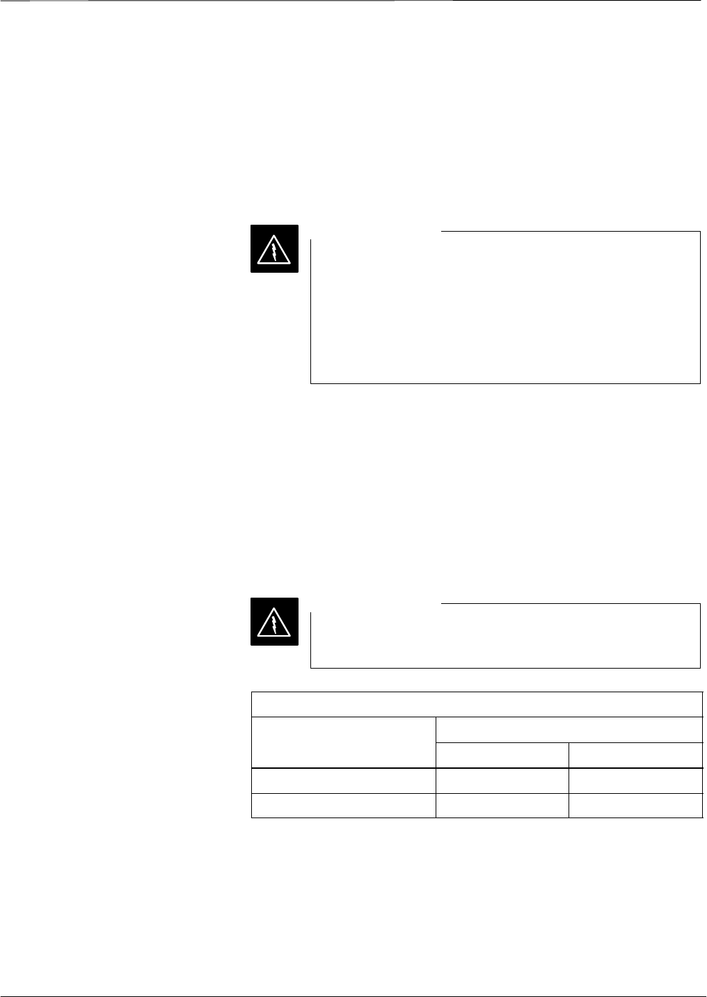
Maximum Permissable
Exposure (MPE) Limit Warning
In order to comply with the FCC guidelines on RF exposure, the
antennas for this equipment must not exceed the maximum gain shown
in the MPE Limits table. Antennas must be installed more than the
minimum distance specified in the MPE Limits table away from persons.
No antenna used with this equipment should be installed in a location in
which any persons are likely to be within the maximum persmissable
distance from the antenna.
Verify that transmitter output is turned off before
performing antenna service within the restricted area.
WARNING
MPE Limits
Parameter Frequency
800 MHz 1.9 GHz
Maximum Gain 5.2dBd 5.5dBi
Distance 1.0m (40 in.) 0.5m (20 in.)
RF Antenna Warning Labels
Your BTS is shipped with one of two different warning labels depending
upon the frequency:
S800 MHz – Motorola Part Number 5488229C09 (1 m label)
S1.9 GHz – Motorola Part Number 5488229C10 (0.5 m label)
You must affix the label to a visible surface near the antenna for all
indoor antenna mounting applications. The label(s) must be visible from

FCC Requirements – continued
DRAFT
SCt300 1X BTS Hardware Installation, ATP, and FRU Procedures JAN 2002
xxii
all directions. Order additional labels as required for your specific
application.
FCC Part 15 Requirements
Part 15.19a(3) – Information to User
This device complies with Part 15 of the FCC Rules. Operation is
subject to the following two conditions: (1) This device may not cause
harmful interference, and (2) this device must accept any interference
received, including interference that may cause undesired operation.
Part 15.21 – Information to User
Changes or modifications not expressly approved by Motorola could
void your authority to operate the equipment.
Part 15.105(b) – Information to User
This equipment has been tested and found to comply with the limits for a
Class B digital device, pursuant to Part 15 of the FCC Rules. These
limits are designed to provide reasonable protection against harmful
interference in a residential installation. This equipment generates, uses
and can radiate radio frequency energy and, if not installed and used in
accordance with the instructions, may cause harmful interference to radio
communications. However, there is no guarantee that interference will
not occur in a particular installation. If this equipment does cause
harmful interference to radio or television reception, which can be
determined by turning the equipment OFF and ON, the user is
encouraged to try to correct the interference by one or more of the
following measures:
SReorient or relocate the receiving antenna.
SIncrease the separation between the equipment and receiver.
SConnect the equipment into an outlet on a circuit different from that to
which the receiver is connected.
SConsult the dealer or an experienced radio/TV technician for help.
FCC Part 68 Requirements
This equipment complies with Part 68 of the Federal Communications
Commission (FCC) Rules. A label located on the upper–right corner of
the right side of the cooling fins contains, among other information, the
FCC Registration Number and Ringer Equivalence Number (REN) for
this equipment. If requested, this information must be provided to the
telephone company.
The REN is useful to determine the quantity of the devices which may
connect to the telephone line. Excessive RENs on the telephone line
may result in the devices not ringing in response to incoming calls. In
most, but not all areas, the sum of the RENs should not exceed five
(5.0). To be certain of the number of devices that may be connected to
the line as determined by the total RENs, contact the telephone company
to determine the maximum REN for the calling area.

FCC Requirements – continued
JAN 2002 xxiii
SCt300 1X BTS Hardware Installation, ATP, and FRU Procedures
DRAFT
If the dial–in site access modem causes harm to the telephone network,
the telephone company will notify you in advance that temporary
discontinuance of service may be required. If advance notice is not
practical, the telephone company will notify you of the discontinuance as
soon as possible. Also, you will be advised of your right to file a
complaint with the FCC if you believe it is necessary.
The telephone company may make changes in its facilities, equipment,
operations, or procedures that could affect the operation of your dial–in
site access modem. If this happens, the telephone company will provide
advance notice so that you can modify your equipment as required to
maintain uninterrupted service.
If you experience trouble with the dial–in site access modem, please
contact:
Motorola Customer Network Resolution Center (CNRC)
3436 N. Kennicot Drive
Arlington Heights, Illinois 60004
Phone Number: 800–433–5202
for repair and/or warranty information. If the trouble is causing harm to
the telephone network, the telephone company may request you to
disconnect the equipment from the network until the problem is solved.
You should not attempt to repair this equipment yourself. This
equipment contains no customer or user–serviceable parts.
Changes or modifications not expressly approved by Motorola could
void your authority to operate this equipment.

Revision History
DRAFT
SCt300 1X BTS Hardware Installation, ATP, and FRU Procedures JAN 2002
xxiv
Manual Number
68P09253A43
Manual Title
SCt300 1X BTS Hardware Installation, ATP, and FRU Procedures
Software Release 2.16.0.x (1.9 GHz)
Version Information
The following table lists the manual version, date of version, and
remarks on the version.
Version
Level Date of Issue Remarks
1JAN 2002 Draft/preliminary version for DE/CIE/DV&V review .
Cellular Manual Revision
Information
The following table lists Cellular Manual Revision (CMR) number, date
of CMR, and remarks on the CMR.
Revision
Level Date of Issue Remarks
CMR No. N.A. No CMRs apply to this manual

Patent Notification
JAN 2002 xxv
SCt300 1X BTS Hardware Installation, ATP, and FRU Procedures
DRAFT
Patent numbers
This product is manufactured and/or operated under one or more of the
following patents and other patents pending:
4128740 4661790 4860281 5036515 5119508 5204876 5247544 5301353
4193036 4667172 4866710 5036531 5121414 5204977 5251233 5301365
4237534 4672657 4870686 5038399 5123014 5207491 5255292 5303240
4268722 4694484 4872204 5040127 5127040 5210771 5257398 5303289
4282493 4696027 4873683 5041699 5127100 5212815 5259021 5303407
4301531 4704734 4876740 5047762 5128959 5212826 5261119 5305468
4302845 4709344 4881082 5048116 5130663 5214675 5263047 5307022
4312074 4710724 4885553 5055800 5133010 5214774 5263052 5307512
4350958 4726050 4887050 5055802 5140286 5216692 5263055 5309443
4354248 4729531 4887265 5058136 5142551 5218630 5265122 5309503
4367443 4737978 4893327 5060227 5142696 5220936 5268933 5311143
4369516 4742514 4896361 5060265 5144644 5222078 5271042 5311176
4369520 4751725 4910470 5065408 5146609 5222123 5274844 5311571
4369522 4754450 4914696 5067139 5146610 5222141 5274845 5313489
4375622 4764737 4918732 5068625 5152007 5222251 5276685 5319712
4485486 4764849 4941203 5070310 5155448 5224121 5276707 5321705
4491972 4775998 4945570 5073909 5157693 5224122 5276906 5321737
4517561 4775999 4956854 5073971 5159283 5226058 5276907 5323391
4519096 4797947 4970475 5075651 5159593 5228029 5276911 5325394
4549311 4799253 4972355 5077532 5159608 5230007 5276913 5327575
4550426 4802236 4972432 5077741 5170392 5233633 5276915 5329547
4564821 4803726 4979207 5077757 5170485 5235612 5278871 5329635
4573017 4811377 4984219 5081641 5170492 5235614 5280630 5339337
4581602 4811380 4984290 5083304 5182749 5239294 5285447 D337328
4590473 4811404 4992753 5090051 5184349 5239675 5287544 D342249
4591851 4817157 4998289 5093632 5185739 5241545 5287556 D342250
4616314 4827507 5020076 5095500 5187809 5241548 5289505 D347004
4636791 4829543 5021801 5105435 5187811 5241650 5291475 D349689
4644351 4833701 5022054 5111454 5193102 5241688 5295136 RE31814
4646038 4837800 5023900 5111478 5195108 5243653 5297161
4649543 4843633 5028885 5113400 5200655 5245611 5299228
4654655 4847869 5030793 5117441 5203010 5245629 5301056
4654867 4852090 5031193 5119040 5204874 5245634 5301188

Patent Notification – continued
DRAFT
SCt300 1X BTS Hardware Installation, ATP, and FRU Procedures JAN 2002
xxvi
Notes

JAN 2002 SCt300 1X BTS Hardware Installation, ATP, and FRU Procedures
DRAFT
Chapter 1: Introduction
Table of Contents
Introduction 1-1. . . . . . . . . . . . . . . . . . . . . . . . . . . . . . . . . . . . . . . . . . . . . . . . . . . . .
Scope of This Document 1-1. . . . . . . . . . . . . . . . . . . . . . . . . . . . . . . . . . . .
Manual Order 1-1. . . . . . . . . . . . . . . . . . . . . . . . . . . . . . . . . . . . . . . . . . . . .
Site Cleanliness 1-2. . . . . . . . . . . . . . . . . . . . . . . . . . . . . . . . . . . . . . . . . . .
Site Manager 1-2. . . . . . . . . . . . . . . . . . . . . . . . . . . . . . . . . . . . . . . . . . . . .
System Diagrams 1-2. . . . . . . . . . . . . . . . . . . . . . . . . . . . . . . . . . . . . . . . . .
Configurations 1-3. . . . . . . . . . . . . . . . . . . . . . . . . . . . . . . . . . . . . . . . . . . .
Required Documents 1-10. . . . . . . . . . . . . . . . . . . . . . . . . . . . . . . . . . . . . . . . . . . . . .
Required Documents 1-10. . . . . . . . . . . . . . . . . . . . . . . . . . . . . . . . . . . . . . .
Installation Tools and Materials 1-11. . . . . . . . . . . . . . . . . . . . . . . . . . . . . . . . . . . . .
Introduction 1-11. . . . . . . . . . . . . . . . . . . . . . . . . . . . . . . . . . . . . . . . . . . . . .
Required Tools and Materials for Installing the
Mounting Bracket on a Pole 1-11. . . . . . . . . . . . . . . . . . . . . . . . . . . . . . . . .
Required Tools and Materials for Installing the
Mounting Bracket on a Rack 1-12. . . . . . . . . . . . . . . . . . . . . . . . . . . . . . . . .
Required Tools and Materials for Installing the
Mounting Bracket on a Concrete Wall 1-12. . . . . . . . . . . . . . . . . . . . . . . . .
ATP Tools and Materials 1-13. . . . . . . . . . . . . . . . . . . . . . . . . . . . . . . . . . . . . . . . . .
Policy 1-13. . . . . . . . . . . . . . . . . . . . . . . . . . . . . . . . . . . . . . . . . . . . . . . . . . .
Test equipment calibration 1-13. . . . . . . . . . . . . . . . . . . . . . . . . . . . . . . . . . .
Test cable calibration 1-13. . . . . . . . . . . . . . . . . . . . . . . . . . . . . . . . . . . . . . .
Equipment Warm–up 1-13. . . . . . . . . . . . . . . . . . . . . . . . . . . . . . . . . . . . . . .
Test Equipment List 1-14. . . . . . . . . . . . . . . . . . . . . . . . . . . . . . . . . . . . . . . .
Optional Equipment 1-16. . . . . . . . . . . . . . . . . . . . . . . . . . . . . . . . . . . . . . . .
FRU Tools and Materials 1-18. . . . . . . . . . . . . . . . . . . . . . . . . . . . . . . . . . . . . . . . . .
Introduction 1-18. . . . . . . . . . . . . . . . . . . . . . . . . . . . . . . . . . . . . . . . . . . . . .
List of FRUs 1-18. . . . . . . . . . . . . . . . . . . . . . . . . . . . . . . . . . . . . . . . . . . . .
Required Tools and Materials to Perform FRU Procedures 1-18. . . . . . . . .
Unit Identification 1-19. . . . . . . . . . . . . . . . . . . . . . . . . . . . . . . . . . . . . . . . . . . . . . . .
Overview 1-19. . . . . . . . . . . . . . . . . . . . . . . . . . . . . . . . . . . . . . . . . . . . . . . .
Installation and ATP Order 1-27. . . . . . . . . . . . . . . . . . . . . . . . . . . . . . . . . . . . . . . . .
Installation Order 1-27. . . . . . . . . . . . . . . . . . . . . . . . . . . . . . . . . . . . . . . . . .
ATP Order 1-27. . . . . . . . . . . . . . . . . . . . . . . . . . . . . . . . . . . . . . . . . . . . . . .
1

Table of Contents – continued
DRAFT
SCt300 1X BTS Hardware Installation, ATP, and FRU Procedures JAN 2002
Notes
1

Introduction
JAN 2002 1-1
SCt300 1X BTS Hardware Installation, ATP, and FRU Procedures
DRAFT
Scope of This Document
This document provides information pertaining to the hardware
installation, cabling installation, ATP and Field Replaceable Unit (FRU)
procedures of the Motorola MicroCell SCt300 CDMA Base
Transceiver Subsystem (BTS) equipment.
The FRU procedures do not cover the replacement of modules inside the
unit.
An individual SCt300 BTS unit will be referred to as the “unit” for the
remainder of this document. A site that contains one or more SCt300
units will be referred to as the “Logical BTS” or “Multi–Unit BTS” for
the remainder of this document.
For detailed installation information of non-Motorola equipment, refer to
the vendor manuals provided with such equipment.
Manual Order
The installation order is the order of the manual starting at Chapter 1 and
continuing through Chapter 5. After hardware installation has been
completed, run the ATP for the system by following the procedures
defined in Chapter 6 of this manual.
Chapter 1
“Introduction” — This is a brief outline of the manual. Also provided is
a list of additional documents and tools necessary to complete the
procedures.
Chapter 2
“Site Preparation” — This chapter contains the necessary information to
verify the condition of the site.
Chapter 3
“Installing Mounting Bracket and Remote GPS” — This chapter
contains the necessary information to install the MicroCell and Surge
Suppressor mounting bracket on a wall, pole, or rack.
Chapter 4
“Preparing Site Cabling for Sites Equipped with Customer–Supplied
Site I/O Interface” — This chapter contains the procedures for installing
the external cabling for sites equipped with the customer–supplied Site
I/O interface.
Chapter 5
“Preparing Site Cabling for Sites Equipped with Optional Primary Surge
Suppressor” — This chapter contains the procedures for installing the
external cabling for sites equipped with the optional Primary Surge
Suppressor.
Chapter 6
“Installing the Unit and Installation Check Off List” — This chapter
contains procedures for installing the unit, mounting the Solar Cover to
the chassis and final Installation Check Off List.
1

Introduction – continued
DRAFT
SCt300 1X BTS Hardware Installation, ATP, and FRU Procedures JAN 2002
1-2
Chapter 7
“Acceptance Test Procedures (Optional)” – This chapter outlines the
ATP used for a field audit after a BTS initial installation, if necessary.
Chapter 8
“Field Replaceable Unit (FRU) Procedures” – This chapter provides the
FRU procedures for the BTS system.
Appendix A
“Outdoor Grounding Guidelines Overview” — This chapter overviews
the grounding information for external units. Use this chapter for
general reference purposes only. It is not meant to replace local code
specifications or site specific directions.
Site Cleanliness
While performing the procedures provided in this document, be sure
that:
Sfor an internal installation, the site is kept clean and free of tracked-in
dirt
Sall packing material has been removed from the equipment.
Sall tools not currently in use are picked-up as the installation
progresses.
Sall trash is removed from the site at the end of each day and after the
installation is complete.
Sequipment is covered with a tarpaulin whenever possible.
Suse a shop-vac whenever you perform an internal installation
procedure that generates dust, such as drilling or cutting.
Site Manager
The site manager is the person in charge of and responsible for the full
site. The installer will be verifying a variety of conditions with the site
manager.
System Diagrams
Figure 1–1 through Figure 1-6 show the MicroCell and optional Primary
Surge Suppressor units mounted on a wall, rack, pole, and frame.
The MicroCell and Primary Surge Suppressor can be mounted indoors
(internal) or can be mounted outdoors (external).
1

Introduction – continued
JAN 2002 1-3
SCt300 1X BTS Hardware Installation, ATP, and FRU Procedures
DRAFT
Configurations
The MicroCell supports single–carrier, omni configurations.
The cover configurations for the MicroCell and Primary Surge
Suppressor are:
SUse solar covers on the Microcell and optional Primary Surge
Suppressor for all outside mounting applications.
SUse fin covers on the Microcell for indoor applications.
SThe Primary Surge Suppressor uses solar covers only.
The battery configurations for the MicroCell unit is:
SShort duration battery
The power configurations for the MicroCell unit is:
SAC power only
SDC power only
SAC power with short duration battery
The synchronization configurations for the MicroCell unit is:
SRemote GPS Receiver – synchronous operation with High Stability
Oscillator (HSO) backup.
SInternal High Stability Oscillator (HSO) only – non–synchronous
operation.
1
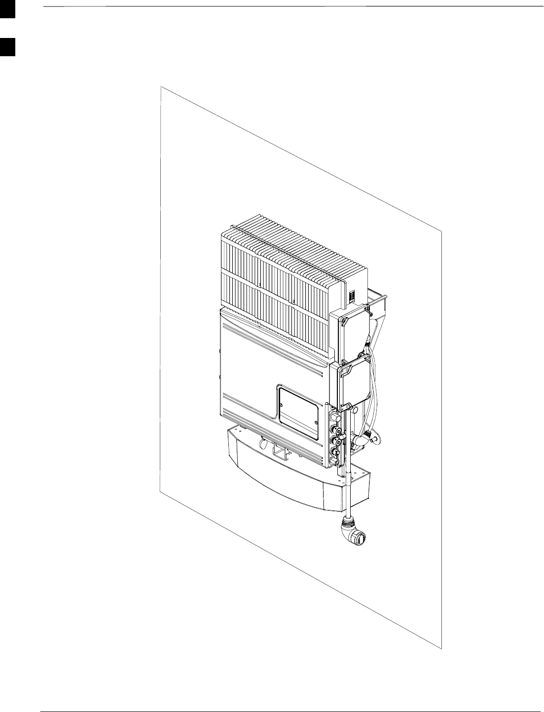
Introduction – continued
DRAFT
SCt300 1X BTS Hardware Installation, ATP, and FRU Procedures JAN 2002
1-4
Figure 1-1: MicroCell Unit Mounted on a Wall
SYSTEM CABLING IS NOT SHOWN.
FIN AND SOLAR COVERS REMOVED
FOR CLARITY.
1
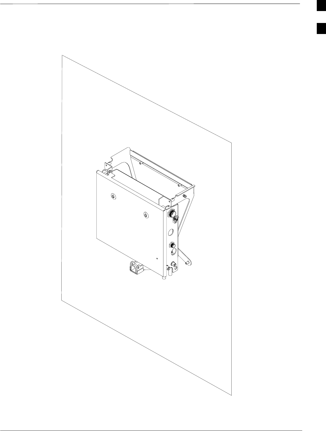
Introduction – continued
JAN 2002 1-5
SCt300 1X BTS Hardware Installation, ATP, and FRU Procedures
DRAFT
Figure 1-2: Primary Surge Suppressor Mounted on a Wall
SYSTEM CABLING IS NOT SHOWN.
SOLAR COVERS REMOVED FOR
CLARITY.
1
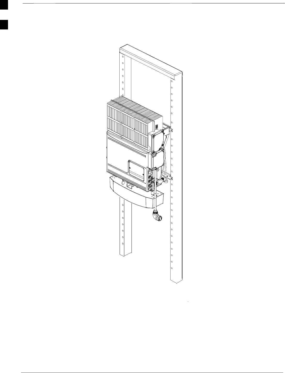
Introduction – continued
DRAFT
SCt300 1X BTS Hardware Installation, ATP, and FRU Procedures JAN 2002
1-6
Figure 1-3: MicroCell Unit Mounted on a Rack
SYSTEM CABLING IS NOT SHOWN.
FIN AND SOLAR COVERS REMOVED
FOR CLARITY.
1
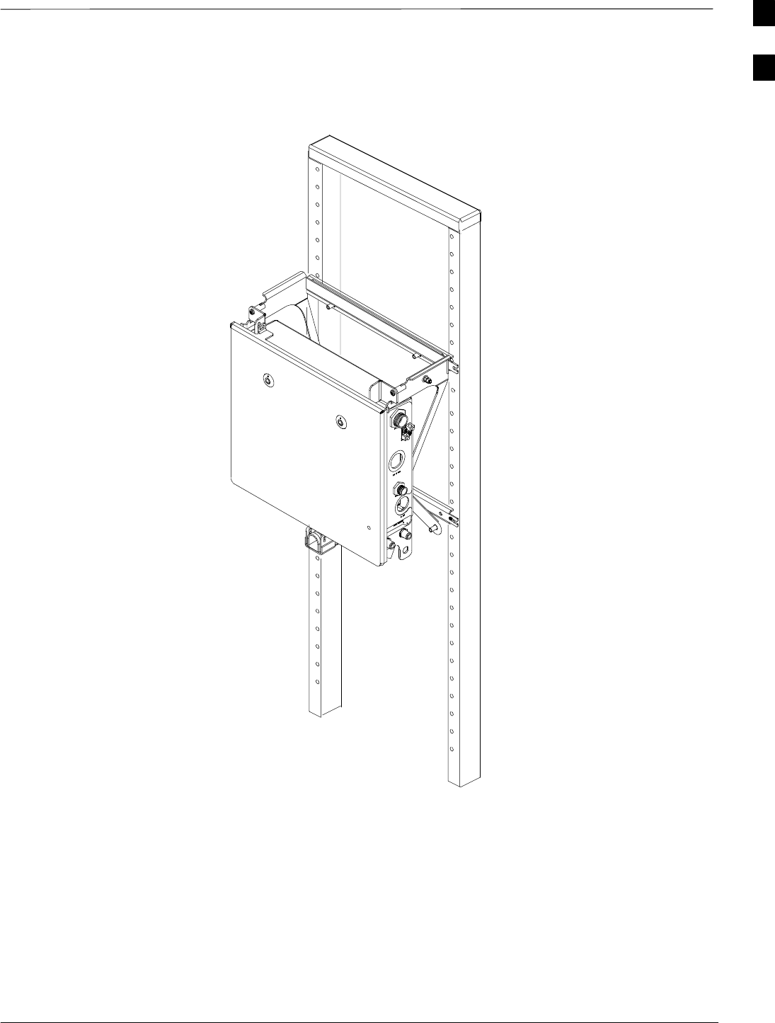
Introduction – continued
JAN 2002 1-7
SCt300 1X BTS Hardware Installation, ATP, and FRU Procedures
DRAFT
Figure 1-4: Primary Surge Suppressor Mounted on a Rack
SYSTEM CABLING IS NOT SHOWN.
FIN AND SOLAR COVERS REMOVED
FOR CLARITY.
1
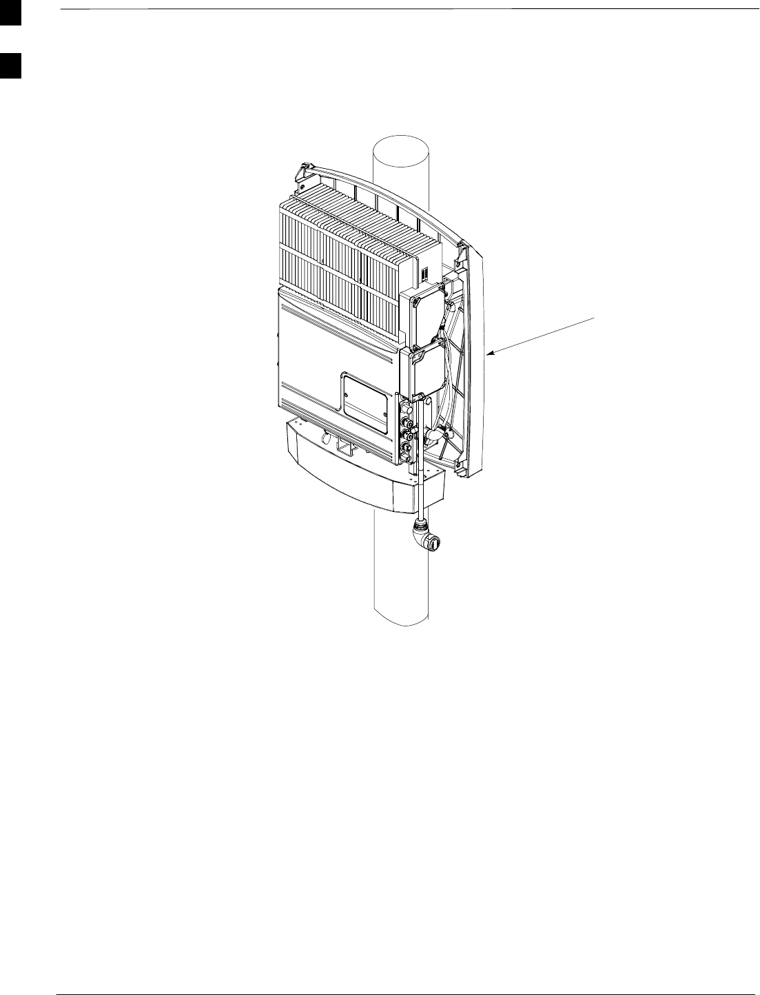
Introduction – continued
DRAFT
SCt300 1X BTS Hardware Installation, ATP, and FRU Procedures JAN 2002
1-8
Figure 1-5: MicroCell Unit Mounted on a Pole
BACK SOLAR COVER
SYSTEM CABLING IS NOT SHOWN.
FRONT SOLAR COVER IS REMOVED
FOR CLARITY.
1
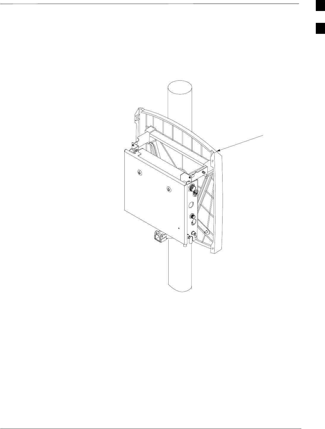
Introduction – continued
JAN 2002 1-9
SCt300 1X BTS Hardware Installation, ATP, and FRU Procedures
DRAFT
Figure 1-6: Primary Surge Suppressor Mounted on a Pole
BACK SOLAR COVER
SYSTEM CABLING IS NOT SHOWN.
FRONT SOLAR COVER IS REMOVED
FOR CLARITY.
1

Required Documents
DRAFT
SCt300 1X BTS Hardware Installation, ATP, and FRU Procedures JAN 2002
1-10
Required Documents
The following documents are required to perform the installation, ATP
and FRU procedures of the cell site equipment:
SSCt300 BTS Hardware Installation, ATP and FRU – 68P09224A55
(This manual)
SGrounding Guidelines for Cellular Radio Installations –
68P81150E62.
SCDMA LMF Operator’s Guide – 68P64114A78.
SSite Document (generated by Motorola Systems Engineering), which
includes:
–site specific documentation
–channel allocation
–contact list (customer)
–ancillary/expendable equipment list
–site wiring lists
–contact list (Motorola support)
–job box inventory
SDemarcation Document (Scope of Work agreement)
SInstallation manuals for non-Motorola equipment (for reference
purposes).
1

Installation Tools and Materials
JAN 2002 1-11
SCt300 1X BTS Hardware Installation, ATP, and FRU Procedures
DRAFT
Introduction
Many of the tools and materials depend on the style of the wall, pole, or
rack that the mounting bracket is being installed on. The tools and
materials required to install the BTS hardware are specified for each
mounting style. Due to the variability of mounting styles, additional
tools and materials may be required to meet specific site needs. This is
outside of the scope of this document and must be evaluated on a site to
site basis.
Also, for each procedure, a tools and materials list is provided within the
procedure.
Motorola kit T393AA is available for most installation styles and
methods. Motorola kit T393AA contains:
STorque driver wrench, 1/4–in. hex female drive, 0–10 N–m
ST20 Torx Tamper Bit, 1/4–in. hex
ST30 Torx Tamper Bit, 1/4–in. hex
SFlathead bit
STorque ratchet wrench 3/8–in. drive, 0–10 N–M (Utica part number
TCI–150 R/A 3/8–in. or equivalent)
S5/16 Breakaway 9–in. lb.
S13/16 Breakaway 38–in. lb.
SWire Crimping Tool
SInstallation Handles, Motorola Part Numbers (Left Handle
0787668C01) and (Right Handle 0787668C02)
SScrews M6x19 (Motorola Part Number 0387541C03)
SBuckle Strap Tool
Required Tools and Materials
for Installing the Mounting
Bracket on a Pole
The following tools and materials in Table 1-1 are required to properly
and safely install the the mounting bracket on a pole.
Table 1-1: Required Tools and Materials for Pole Mounting
Hand Tools Materials Power Tools
Safety Glasses MicroCell mounting kit No Power Tools Required
Bucklestrap Cutting Tool (Motorola
part number 6604809N01) electrical tape
(customer supplied)
T30 TORX tamper bit, 1/4–in. hex
Torque driver wrench, 1/4–in. hex
female drive, 0–10 N–M
Ball Peen (Metal Working) Hammer
Heavy Gloves
Tape Measure
1

Installation Tools and Materials – continued
DRAFT
SCt300 1X BTS Hardware Installation, ATP, and FRU Procedures JAN 2002
1-12
Required Tools and Materials
for Installing the Mounting
Bracket on a Rack
The following tools and materials in Table 1-2 are required to properly
and safely install the mounting bracket on a rack.
Table 1-2: Required Tools and Materials for Rack Mounting
Hand Tools Materials Power Tools
T30 Torx tamper bit, 1/4–in. hex MicroCell Mounting Kit No Power Tools Required
Torque driver wrench, 1/4–in. hex
female drive, 0–10 N–M Four machine screws 12–24
5/8-in. self tapping (customer
supplied)
Chalk or marker to mark
location on rack
(customer supplied)
electrical tape
(customer supplied)
Required Tools and Materials
for Installing the Mounting
Bracket on a Concrete Wall
The following tools and materials in Table 1-3 are required to properly
and safely install the mounting bracket on a concrete wall.
Table 1-3: Required Tools and Materials for Concrete Wall Mounting
Hand Tools Materials Power Tools
T30 Torx tamper bit, 1/4–in hex metal shim material Hilti wall drilling rig
15/16-in. (23.8 mm) socket, a ratchet
wrench, and an 18-in. (45.7 cm)
breaker bar
Hilti anchors (for each
bracket) Hilti DCM 18–14 metric bit
safety glasses MicroCell Mounting Kit shop vacuum
chalk for marking outline on wall electrical tape
tape measure (customer supplied)
4-ft (1.22 m) bubble level
rubber mallet
ear plugs
dust mask
1

ATP Tools and Materials
JAN 2002 1-13
SCt300 1X BTS Hardware Installation, ATP, and FRU Procedures
DRAFT
Policy
To ensure consistent, reliable and repeatable test results, test equipment
meeting the following technical criteria should be used to perform the
ATP on the BTS equipment.
During manual testing, you can substitute supported test
equipment with other test equipment models not supported
by the LMF. However, they must meet the same technical
specifications.
NOTE
It is the responsibility of the customer to account for any measurement
variances and /or additional losses / inaccuracies that can be introduced
as a result of these substitutions. Before beginning the ATP or
troubleshooting, make sure that the test equipment needed is on hand
and operating properly.
Test equipment calibration
Optimum system performance and capacity depend on regular test
equipment service, calibration, and characterization. Follow the original
equipment manufacture (OEM) recommended maintenance and
calibration schedules closely.
Test cable calibration
Equipment test cables are very important in the ATP. It is recommended
that the cable calibration be run at every BTS with the test cables
attached. This method compensates for test cable insertion loss within
the test equipment itself. No other allowance for test cable insertion loss
needs to be made during the performance of tests.
Another method is to account for the loss by entering it into the Local
Maintenance Facility (LMF) during the optimization procedure. This
method requires accurate test cable characterization in a lab
environment. The cable should be tagged with the characterization
information prior to field optimization.
Equipment Warm–up
After arriving at the a site, the test equipment should be plugged in and
turned on to allow warm up and stabilization to occur for as long as
possible. The following pieces of test equipment must be warmed–up for
a minimum of 60 minutes prior to the ATP.
SCommunications Test Set
SPower Meter
1

ATP Tools and Materials – continued
DRAFT
SCt300 1X BTS Hardware Installation, ATP, and FRU Procedures JAN 2002
1-14
Test Equipment List
The following pieces of test equipment are required during the ATP.
Common assorted tools like screwdrivers and keys are not listed but are
still required. Read the owners manual on all of the following major
pieces of test equipment to understand their individual operation prior to
use in optimization.
Always refer to specific OEM test equipment
documentation for detailed operating instructions.
NOTE
CDMA LMF Hardware Requirements
A CDMA LMF computer platform that meets the following
requirements (or better) is recommended:
SNotebook computer
S266 MHz (32 bit CPU) Pentium processor
S4 Gbyte internal hard disk drive
SColor display with 1024 x 768 resolution
S128 MB RAM
SCD ROM drive
S3 1/2 inch floppy drive
SSerial port (COM 1)
SSerial port (COM 2)
SParallel port (LPT 1)
SPCMCIA Ethernet interface card (for example, 3COM Etherlink III)
with a 10Base–T–to–coax adapter
SWindows 98 SE
If 800 x 600 pixel resolution is used, the CDMA LMF
window must be maximized after it is displayed.
NOTE
RS232 to GPIB Interface
One National Instruments GPIB–232–CT with Motorola
CGDSEDN04X RS232 serial cable or equivalent; used to interface the
LMF to the test equipment.
A Standard RS–232 cable can be used with the following modifications:
SPin 8 (CTS) does not have to be jumpered/shorted to the others as it is
a driver output. The DTR is already a driver output signal. The other
pins are to receivers. Short pins 7, 1, 4, 6 on each cable end:
1

ATP Tools and Materials – continued
JAN 2002 1-15
SCt300 1X BTS Hardware Installation, ATP, and FRU Procedures
DRAFT
Communications Test Set
This procedure requires one of the following test sets:
SMotorola CyberTest
SAdvantest R3465 and HP 437B or Gigatronics 8541C Power Meter
SHewlett–Packard HP 8935
SHewlett–Packard HP8921 (w/CDMA and PCS interface for 1.7/1.9
GHz) and HP 437B or Gigatronics Power Meter.
4–port 10 Base T ethernet hub (optional)
One 4–port, 10 base T, 10 Mbps, ethernet hub with BNC connector.
This is used for LMF to BTS ethernet connections. This is used to
connect the PCMCIA serial I/O port of the LMF to the RJ45 ethernet
cable.
GPIB cables
Two Hewlett Packard 10833A or equivalent; 1 or 2 meters long used to
interconnect test equipment and LMF terminal.
Power meter
This procedure requires one of the following power meters:
SGigatronics Model 8541C with 80601A power sensor capable of
measuring from –70 dBm to +23 dBm; supported by the LMF to
perform BTS Total Power measurement.
SHewlett–Packard Model HP437B with HP8481A power sensor
capable of measuring from –30 dBm to 20 dBm.
RF attenuators
30 dB, 10 Watt minimum RF attenuator to attenuate the transmitter
output for MicroCell tests.
BTS serial cable
One BTS serial cable to connect LMF to MMI/LMF connector.
Male N to male N cables
The following male N to male N cables are necessary to do this
procedure:
SOne male N to male N cable. The short RF test cable used for cable
calibration.
STwo male N to male N cables. The transmit RF test cable and the
receive RF test cable used for ATP.
Male BNC to male N cable
One male BNC to male N cable. This cable is used to allow
self–calibration of the Communication Test Set.
1

ATP Tools and Materials – continued
DRAFT
SCt300 1X BTS Hardware Installation, ATP, and FRU Procedures JAN 2002
1-16
Male BNC to male cable
One male BNC to male cable. This cable connects the 2 Second
Reference to the external trigger of the Communication Test Set.
Male BNC to Male SMA cable
Two male BNC to male SMA cables. These cables are is used to
connect the BTS 19.6608 MHz and 2 Second Reference to the
Communication Test Set.
50 Ohm load
One male N 50 Ohm load to terminate the unused antenna port for
MicroCell receive testing.
15 to 9–pin DSUB Adapter
One 15 to 9–pin DSUB adapter. This allows connection between the
MMI/LMF connector on the BTS and the DB9 cable.
Female N to female N adapter
One female N to female N adapter. This allows connection between the
short RF test cable and the transmit RF test cable or the receive RF test
cable.
BNC–T connectors
One female and one male port BNC–T connector. This connects the 2
Second Reference to the external trigger of the Communication Test Set.
Optional Equipment
None of the optional equipment specified here is supported
by the LMF in automated tests. It is meant to serve as a list
of additional equipment that might be required during
maintenance and troubleshooting operations.
NOTE
Digital multimeter
Fluke Model 8062A with Y8134 test lead kit or equivalent; used for
precision DC and AC measurements, requiring 4–1/2 digits.
Frequency counter
Stanford Research Systems SR620 or equivalent. If direct measurement
of the 19.6608 MHz references is required.
Spectrum analyzer
Spectrum Analyzer (HP8594E with CDMA personality card) or
equivalent. Required for manual tests other than standard tests
performed by the LMF.
1

ATP Tools and Materials – continued
JAN 2002 1-17
SCt300 1X BTS Hardware Installation, ATP, and FRU Procedures
DRAFT
Span line (T1/E1) verification equipment
As required for local application.
RF test cable (if not provided with test equipment)
Motorola model TKN8231A. Used to connect test equipment to the
BTS during ATP or general troubleshooting procedures.
Oscilloscope
Tektronics model 2445 or equivalent. Used for waveform viewing,
timing and measurements during general troubleshooting procedures.
CDMA subscriber mobile or portable radiotelephone
CDMA compatible with power supply and antenna. Used to provide test
transmission and reception during BTS maintenance and
troubleshooting. Two radios will be required for system and drive
around testing after BTS installation and optimization.
1

FRU Tools and Materials
DRAFT
SCt300 1X BTS Hardware Installation, ATP, and FRU Procedures JAN 2002
1-18
Introduction
The following is a list of the FRUs for the Microcell unit and a list of the
tools and materials necessary to perform the FRU installation and
removal procedures:
List of FRUs
The following is a list of FRUs for the unit:
1. Site I/O Junction Box with Primary Surge Suppressor – Kit T450AE
2. Site I/O Junction Box without Primary Surge Suppressor – Kit
T450AA
3. RGPS Head – Kit T472AP
4. Short Duration Battery – Kit T348AE
5. Primary Surge Suppressor – Kit T449AA
6. AC Installation Box – Kit T449AB
MicroCell
1. A Band BTS with HSO – Kit SG1478AA
2. A Band BTS without HSO – Kit SG1479AA
3. B Band BTS with HSO – Kit SG1486AA
4. B Band BTS without HSO – Kit SG1487AA
5. Solar Cover – Kit T451AA
6. Fin Cover – Kit T389AB
Required Tools and Materials
to Perform FRU Procedures
Table 1-4 lists the required tools and materials to perform the FRU
installation procedures.
Table 1-4: Required Tools and Material to Perform FRU Procedures
Hand Tools Materials Power Tools
T30 Torx tamper bit, 1/4–in. hex Applicable FRU None Required
T20 Torx tamper bit, 1/4–in. hex Installation handles
Torque driver wrench, 1/4–in hex
female drive, 0–10 N–M
(optional)
13 mm torque wrench
5/16 breakaway torque wrench
13/16 breakaway torque wrench
1
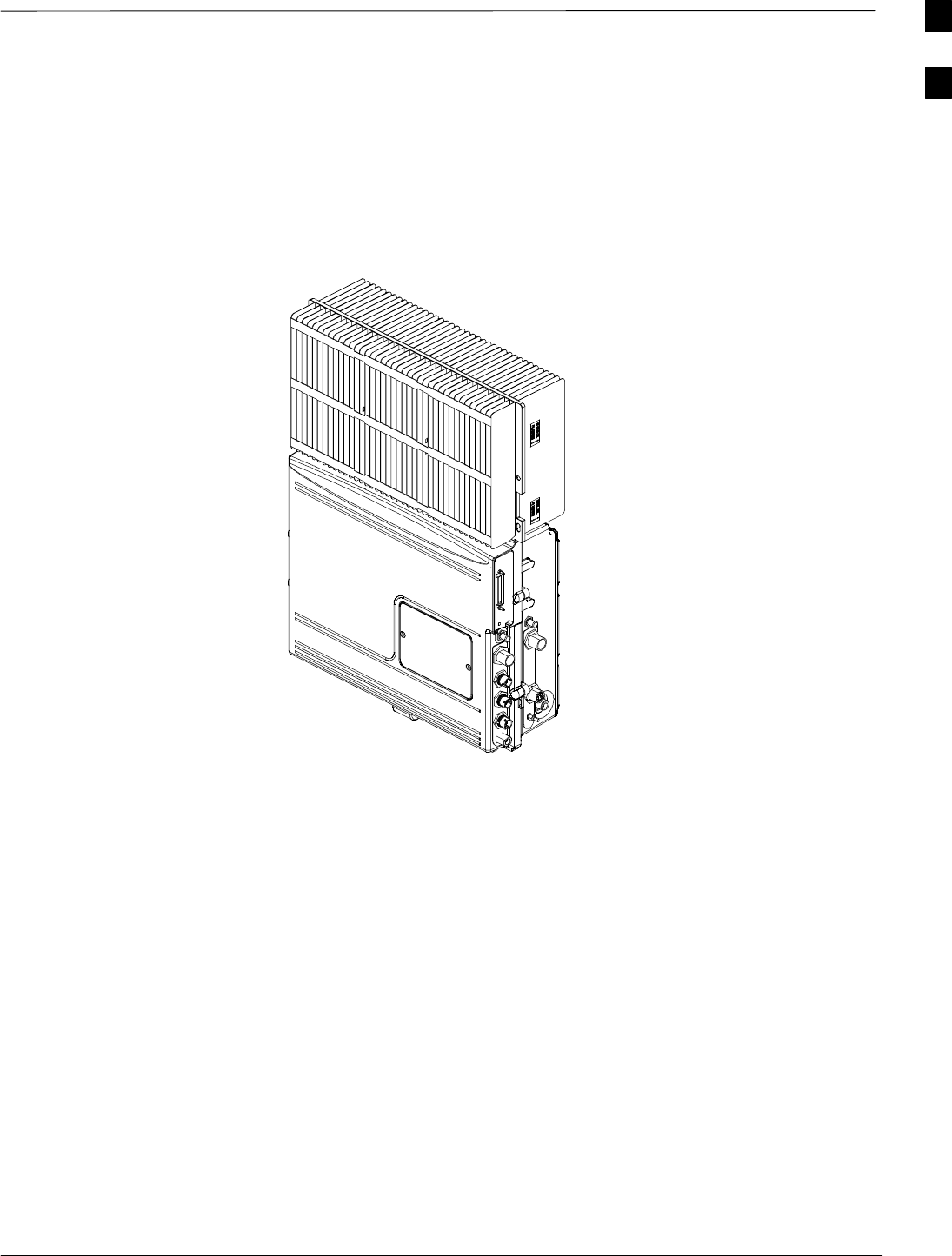
Unit Identification
JAN 2002 1-19
SCt300 1X BTS Hardware Installation, ATP, and FRU Procedures
DRAFT
Overview
Figure 1-7 through Figure 1-19 show the various components of the
SCt300 MicroCell system.
Figure 1-7: MicroCell Unit
1
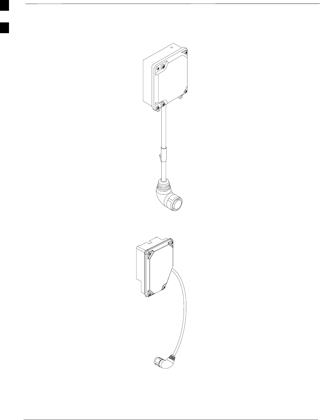
Unit Identification – continued
DRAFT
SCt300 1X BTS Hardware Installation, ATP, and FRU Procedures JAN 2002
1-20
Figure 1-8: Site I/O Junction Box and Cable
Figure 1-9: Subscriber Unit (SU) and Cable
1
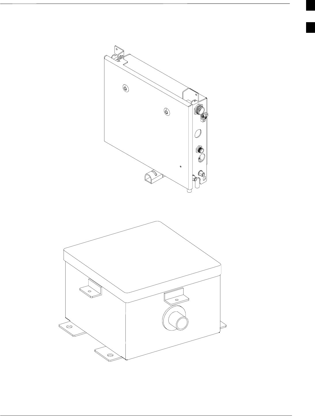
Unit Identification – continued
JAN 2002 1-21
SCt300 1X BTS Hardware Installation, ATP, and FRU Procedures
DRAFT
Figure 1-10: Primary Surge Suppressor (Optional)
Figure 1-11: AC Installation Box (Optional)
1
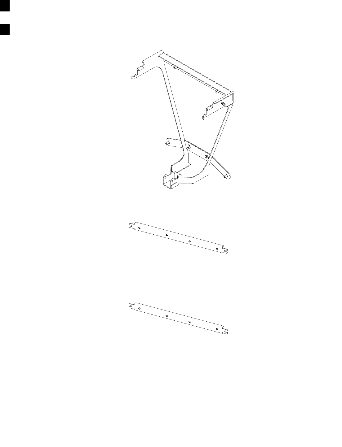
Unit Identification – continued
DRAFT
SCt300 1X BTS Hardware Installation, ATP, and FRU Procedures JAN 2002
1-22
Figure 1-12: Mounting Bracket for both MicroCell and Primary Surge Suppressor
Figure 1-13: Adapters for Rack Mounting
1
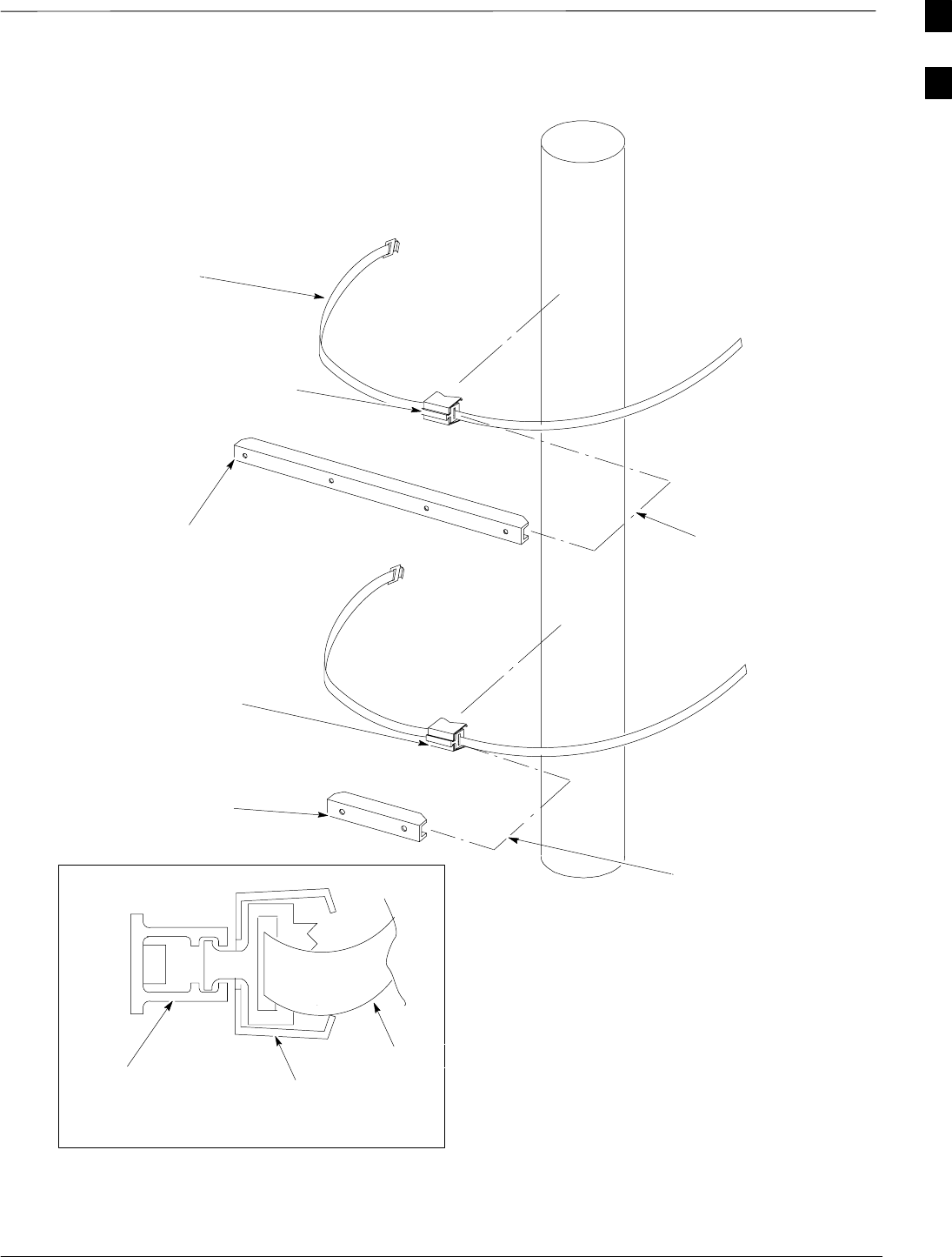
Unit Identification – continued
JAN 2002 1-23
SCt300 1X BTS Hardware Installation, ATP, and FRU Procedures
DRAFT
Figure 1-14: Adapters for Pole Mounting
CHANNEL EXTRUSION
CHANNEL CLAMP
SEE DETAIL A
BUCKLESTRAP
UPPER CHANNEL
EXTRUSION
CHANNEL CLAMP
CHANNEL CLAMP
LOWER CHANNEL
EXTRUSION
DETAIL A
SEE DETAIL A
BUCKLESTRAP
1
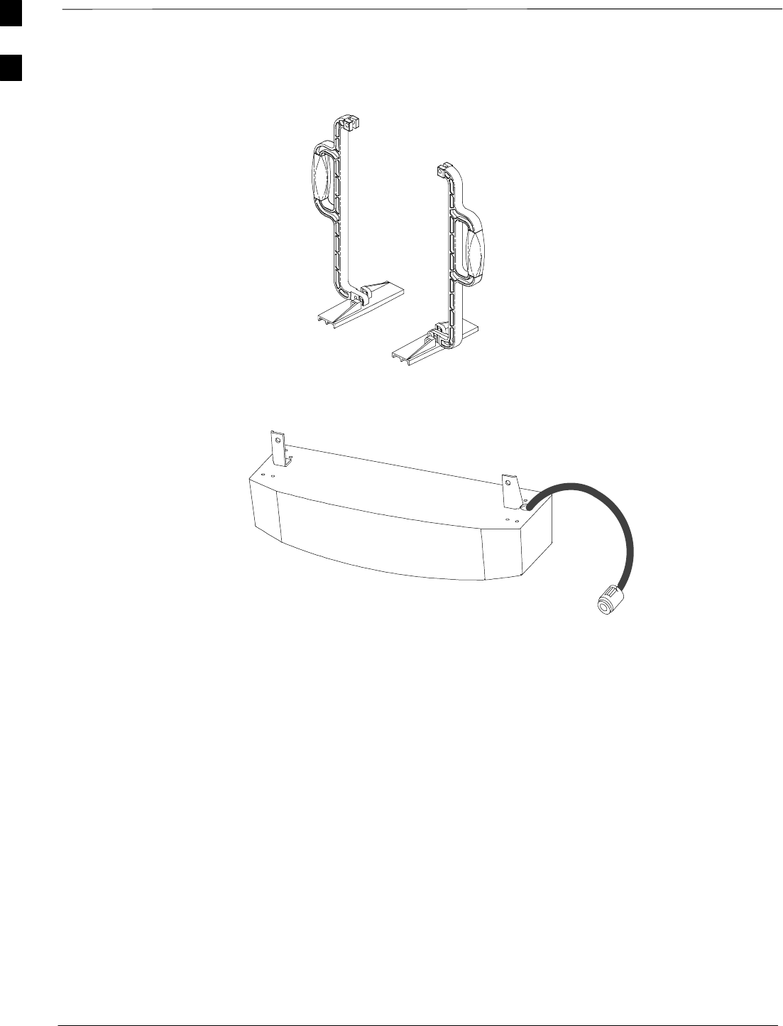
Unit Identification – continued
DRAFT
SCt300 1X BTS Hardware Installation, ATP, and FRU Procedures JAN 2002
1-24
Figure 1-15: Installation Handles for Lifting Unit (Optional)
Figure 1-16: Short Duration Battery (Optional)
1
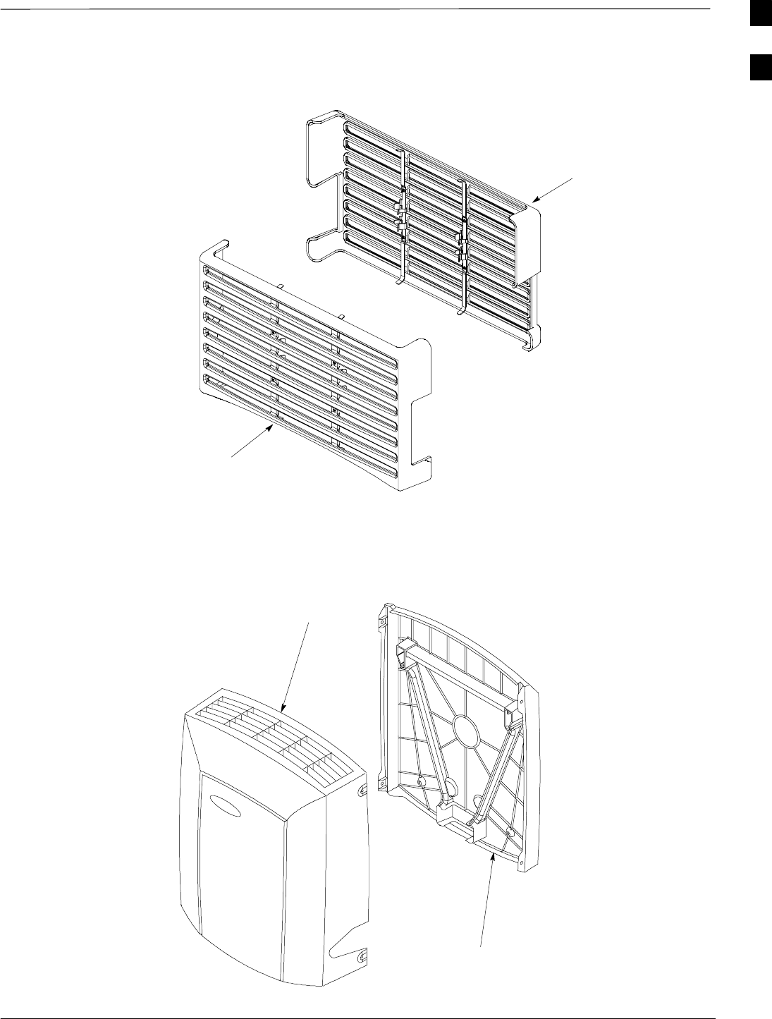
Unit Identification – continued
JAN 2002 1-25
SCt300 1X BTS Hardware Installation, ATP, and FRU Procedures
DRAFT
Figure 1-17: Front and Back Fin Covers
BACK COVER
FRONT COVER
Figure 1-18: Front and Back Solar Covers for MicroCell
FRONT COVER
BACK COVER
1
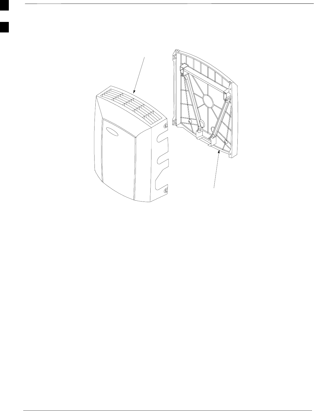
Unit Identification – continued
DRAFT
SCt300 1X BTS Hardware Installation, ATP, and FRU Procedures JAN 2002
1-26
Figure 1-19: Front and Back Solar Covers for Surge Suppressor
FRONT COVER
BACK COVER
1

Installation and ATP Order
JAN 2002 1-27
SCt300 1X BTS Hardware Installation, ATP, and FRU Procedures
DRAFT
Installation Order
The pieces of the MicroCell and Primary Surge Suppressor units should
be installed in the following order.
1. Unpack and inspect hardware
2. Install mounting hardware and bracket(s)
3. Install back solar cover to mounting bracket (required for outdoor
installations and optional for indoor applications if fin covers will
not be used).
4. Install RGPS head.
5. Prepare site cabling.
6. Install back fin cover to unit (required for indoor applications if solar
covers will not be used).
7. Attach installation handles to unit (optional).
8. Attach and secure unit to mounting bracket.
9. Remove installation handles (if used).
10. Attach and secure Primary Surge Suppressor to mounting bracket
(optional).
11. Attach all ground cabling to unit(s).
12. Remove Site I/O dust cover.
13. Attach Site I/O junction box to unit.
14. Attach Subscriber Unit (SU) to unit.
15. Attach front fin cover (required for indoor applications if solar
covers will not be used).
16. Install short duration battery (if required).
17. Attach all cables to unit(s).
18. Terminate all unused connections.
19. Attach front solar cover (required for outdoor installations and
optional for indoor applications if fin covers will not be used).
ATP Order
The ATP for the MicroCell unit is performed in the following sequence:
1. BTS preparation
2. Connecting the LMF to the BTS
3. Connecting test equipment to the BTS and LMF
4. Establishing an MMI communications session
5. Setting customer operating channel
6. Synchronization verification
7. Install LMF program and binaries
8. Start LMF and log on to BTS
9. Update BTS–specific CDF file device load version
10. Download and enable MAWI
1

Installation and ATP Order – continued
DRAFT
SCt300 1X BTS Hardware Installation, ATP, and FRU Procedures JAN 2002
1-28
11. Test equipment setup (test set calibration/GPIB address & clock
setup)
12. Test equipment selection
13. Power meter calibration
14. Test cable calibration
15. Create CAL file
16. RF path audit
17. TX and RX acceptance tests
18. Subscriber unit test and setup
19. Generate an ATP report
20. Copy LMF CAL file to CBSC
21. Terminate LMF session/leave the site
Frequency Hopping Pilot
Beacon (FHPB) ATP Order
The ATP for a MicroCell that is configured as a Frequency Hopping
Pilot Beacon is performed in the following sequence:
1. Create CAL file
2. RF path audit
3. TX and RX Acceptance tests
4. Generate an ATP Report
5. Copy LMF CAL file to CBSC
6. Terminate LMF session/leave the site
1

JAN 2002 SCt300 1X BTS Hardware Installation, ATP, and FRU Procedures
DRAFT
Chapter 2: Site Preparation
Table of Contents
Site Preparation Overview 2-1. . . . . . . . . . . . . . . . . . . . . . . . . . . . . . . . . . . . . . . . .
Overview 2-1. . . . . . . . . . . . . . . . . . . . . . . . . . . . . . . . . . . . . . . . . . . . . . . .
External Installation Versus Internal Installation 2-1. . . . . . . . . . . . . . . . . .
Verifications and Procedures 2-1. . . . . . . . . . . . . . . . . . . . . . . . . . . . . . . . .
Site Manager 2-1. . . . . . . . . . . . . . . . . . . . . . . . . . . . . . . . . . . . . . . . . . . . .
Verifications and Inspections 2-1. . . . . . . . . . . . . . . . . . . . . . . . . . . . . . . . .
Site Inspections 2-2. . . . . . . . . . . . . . . . . . . . . . . . . . . . . . . . . . . . . . . . . . . . . . . . . .
Inspection Overview 2-2. . . . . . . . . . . . . . . . . . . . . . . . . . . . . . . . . . . . . . .
Deficiencies 2-2. . . . . . . . . . . . . . . . . . . . . . . . . . . . . . . . . . . . . . . . . . . . . .
What to Inspect 2-2. . . . . . . . . . . . . . . . . . . . . . . . . . . . . . . . . . . . . . . . . . .
Antenna and Tower Inspections 2-2. . . . . . . . . . . . . . . . . . . . . . . . . . . . . .
Structural Inspections and Verifications 2-3. . . . . . . . . . . . . . . . . . . . . . . .
Environmental Inspections (Indoor Only) 2-5. . . . . . . . . . . . . . . . . . . . . . .
Grounding Inspections 2-5. . . . . . . . . . . . . . . . . . . . . . . . . . . . . . . . . . . . . .
Prepare Site for the Arrival of the Equipment 2-6. . . . . . . . . . . . . . . . . . . . . . . . . .
Description 2-6. . . . . . . . . . . . . . . . . . . . . . . . . . . . . . . . . . . . . . . . . . . . . . .
Equipment Arrival 2-6. . . . . . . . . . . . . . . . . . . . . . . . . . . . . . . . . . . . . . . . .
Securing Fluorescent Lights 2-6. . . . . . . . . . . . . . . . . . . . . . . . . . . . . . . . .
Procedure to Prepare the Site for the Equipment 2-7. . . . . . . . . . . . . . . . . .
Dimensions and Clearances 2-8. . . . . . . . . . . . . . . . . . . . . . . . . . . . . . . . . . . . . . . .
Overview 2-8. . . . . . . . . . . . . . . . . . . . . . . . . . . . . . . . . . . . . . . . . . . . . . . .
Dimensions and Clearances 2-8. . . . . . . . . . . . . . . . . . . . . . . . . . . . . . . . . .
Unit Dimensions 2-10. . . . . . . . . . . . . . . . . . . . . . . . . . . . . . . . . . . . . . . . . .
Unit Clearances 2-11. . . . . . . . . . . . . . . . . . . . . . . . . . . . . . . . . . . . . . . . . . .
2

Table of Contents – continued
DRAFT
SCt300 1X BTS Hardware Installation, ATP, and FRU Procedures JAN 2002
Notes
2

Site Preparation Overview
JAN 2002 2-1
SCt300 1X BTS Hardware Installation, ATP, and FRU Procedures
DRAFT
Overview
This chapter provides the procedures and information to verify that the
site is ready to have the equipment installed. It also provides procedures
to ensure the safety of the installation personnel, protect the equipment
from damage, and verify the site layout parameters.
External Installation Versus
Internal Installation
The MicroCell system can be installed outdoors (external) or indoors
(internal). The site preparation depends on the type of installation and
the site characteristics. Most preparations apply to both types (indoor
and outdoor) of installations. It is stated when a preparation applies to
only one type of installation.
All indoor installations must be in a restricted access location.
Verifications and Procedures
The verifications and procedures provided in this chapter are:
SExternal site inspections
SInternal site inspections
SPreparing site for the arrival of equipment
SSite layout verification
Site Manager
The site manager is the person in charge of and responsible for the full
site.
Verifications and Inspections
Verifications typically have the installer check with the site manager that
a condition has been previously checked or procedure previously
performed and meets a stated specification.
Inspections typically have the installer personally checking that a
condition or item meets stated specifications.
2

Site Inspections
DRAFT
SCt300 1X BTS Hardware Installation, ATP, and FRU Procedures JAN 2002
2-2
Inspection Overview
Inspect the site to verify that the necessary equipment has been properly
installed. Also, as part of the inspection, verify that the equipment is
adequate to support the Motorola equipment. Not all inspections may
apply to every site. The site characteristics determine which inspections
apply.
Installation of ancillary equipment (e.g., power supplies,
terminal blocks, etc.) may be the responsibility of the
installer. Refer questions to your Motorola Program
Manager.
NOTE
Deficiencies
Notify responsible persons of any deficiencies as soon as possible, if the
installer is not responsible for correcting the noted deficiencies.
Deficiencies may need to be corrected before any installation can start.
What to Inspect
The following external items should be inspected and compared against
any related site-specific documentation.
STowers
SAntennas
SExternal ground systems
SClearances for units
SMounting Structures
Additionally, for all sites the incoming power should be inspected and
compared against any related site-specific documentation.
Antenna and Tower
Inspections
Documentation
The vendor responsible for supplying the towers should leave the
installation documentation at the site after the tower has been erected.
Review this documentation and compare it with any related site-specific
documents.
Inspection
Inspect the following:
STower painting
STower lighting (beacons)
SAntenna and transmission line installation
SGrounding.
2

Site Inspections – continued
JAN 2002 2-3
SCt300 1X BTS Hardware Installation, ATP, and FRU Procedures
DRAFT
Structural Inspections and
Verifications
Wall loading capacity
Verify with the site manager that the wall loading capacity has been
previously checked by a qualified Civil Engineer and meets the
specifications stated in the site-specific documentation.
Pole loading capacity
Verify with the site manager that the pole loading capacity has been
previously checked and meets the specifications stated in the
site-specific documentation.
Site power
Verify with the site manager that site power has been previously checked
and meets the specifications stated in the site-specific documentation.
Cabling rack
For indoor installations inspect the cable rack for proper installation. The
cable racks should be at least 7 ft from the floor. The cable racks should
be electrically tied together with 6 AWG wire, except cable racks that are
in an isolated ground zone.
Fire protection
For indoor installations verify with the site manager that some type of
fixed fire suppression equipment is installed. The possible types are:
SHalon gas system, recommended for cell sites because:
–Halon extinguishes a fire without removing oxygen from a room.
–Halon is clean, allowing for quick cleanup after a fire.
–Halon will not damage the cell site equipment.
SCO2 (carbon dioxide) system.
SSprinkler system. “Dry pipe” sprinkler systems that remove all power
to a room before filling the overhead sprinklers with water are
recommended.
In addition to the fixed fire suppression equipment, there
should be at least two 5-lb ABC class portable fire
extinguishers on the premises before equipment installation
begins.
WARNING
Fire fighting procedures
Cellular infrastructure equipment contains various materials which can
decompose into toxic compounds during intense heat. When fire
2
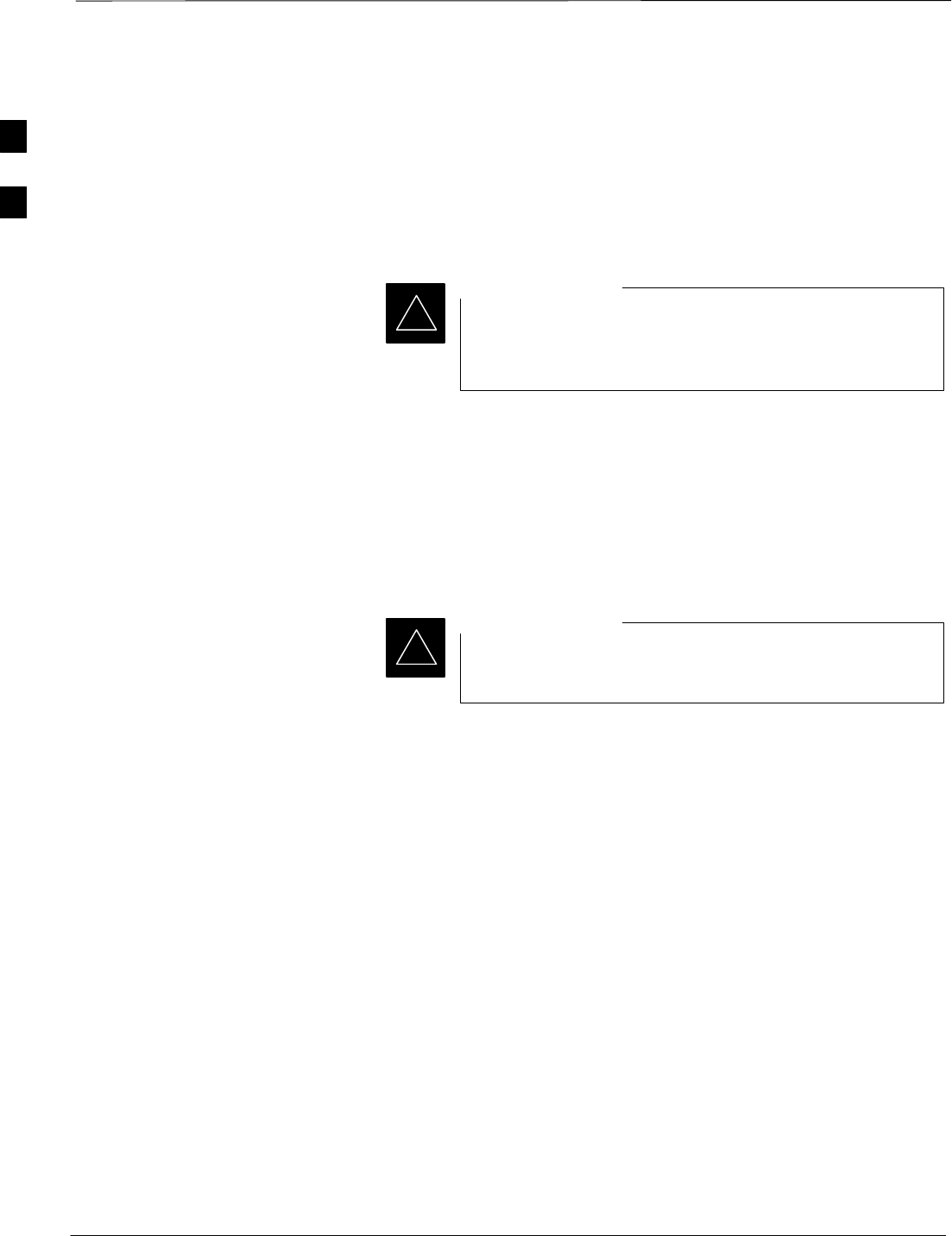
Site Inspections – continued
DRAFT
SCt300 1X BTS Hardware Installation, ATP, and FRU Procedures JAN 2002
2-4
fighting conditions are severe, wear full protective clothing, including
helmet, self–contained, positive pressure or pressure demand breathing
apparatus, bunker coat and pants, bands around arms, waist and legs,
face mask, and protective covering for exposed areas of the head.
Product disposal
The cooling system of the SCt300 BTS product contains
Fluorinert FC–84. The cooling system is sealed before
shipment and should not be incinerated.
IMPORTANT
*
The Material Safety Data Sheet (MSDS) for Fluorinert FC–84 suggests
reclaiming the fluid if feasible. Contact the following office for
information:
3M Center – Performance Materials Division
Building 223–6S–04
St. Paul, MN 55144
800–833–5045
The short duration battery is a lead acid battery. Do not
incinerate.
IMPORTANT
*
The Material Safety Data Sheet (MSDS) for Lead Acid
Batteries states the spent battery should be sent to a secondary lead
smelter for recycling.
Antenna cables and ports
Inspect the antenna cables and ports to verify that:
SAll antenna cables have been properly labeled.
SAntenna ports have been properly weatherproofed.
SAn adequate number of ports exist to handle all of the required
antenna runs.
SLightning arrestors have been installed at the site (sites equipped with
optional Primary Surge Suppressor do not require this). Lightning
arrestors are shipped with the optional Primary Surge Suppressor and
Primary Surge Suppressor expansion kit.
SFor some systems, special ports may be required (refer to the
site-specific information for further details).
2

Site Inspections – continued
JAN 2002 2-5
SCt300 1X BTS Hardware Installation, ATP, and FRU Procedures
DRAFT
Alarms
Verify with the site manager that any of the following alarms called out
in the site-specific documentation have been installed and previously
checked for meeting the site-specific documentation specifications.
Svandalism
Ssurface water
Sintrusion
Sfire
Sbuilding high/low temperatures
Sany customer-specific options.
The interface of the alarms to the Motorola equipment will be part of the
cell site equipment installation.
Environmental Inspections
(Indoor Only)
Temperature control
Verify with the site manager that the cell site building has been
previously checked for the ability to maintain a temperature range as
specified by Motorola. The life span of electronic equipment is
shortened by environmental variations, even though it is designed to
operate in extreme temperatures.
Grounding Inspections
For external installations
For outside installations refer to the site specific documentation.
For internal installations
For indoor installations refer to the Grounding Guideline for Cellular
Radio Installations (68P81150E62) for all grounding inspection
procedures.
Verify the following:
SAll ground cables have a bend radius of 20 cm (8 inches) or more.
SMetallic lines (span, phone[modem], RGPS, power and antenna) that
enter or leave the site should be equipped with a 3-electrode gas tube
protector. The ground side of the gas tubes should be tied to the
Master Ground Bus (MGB). This is not necessary if your site is
equipped with the Primary Surge Suppressor.
SAll installed cable racks (in the same ground zone) are jumpered
together.
Cable racks in an Isolated Ground Zone (IGZ) are not to be
connected to a cable rack in a non-IGZ. For more
information on IGZ, see Grounding Guideline for Cellular
Radio Installations, Motorola part number 68P81150E62.
WARNING
2
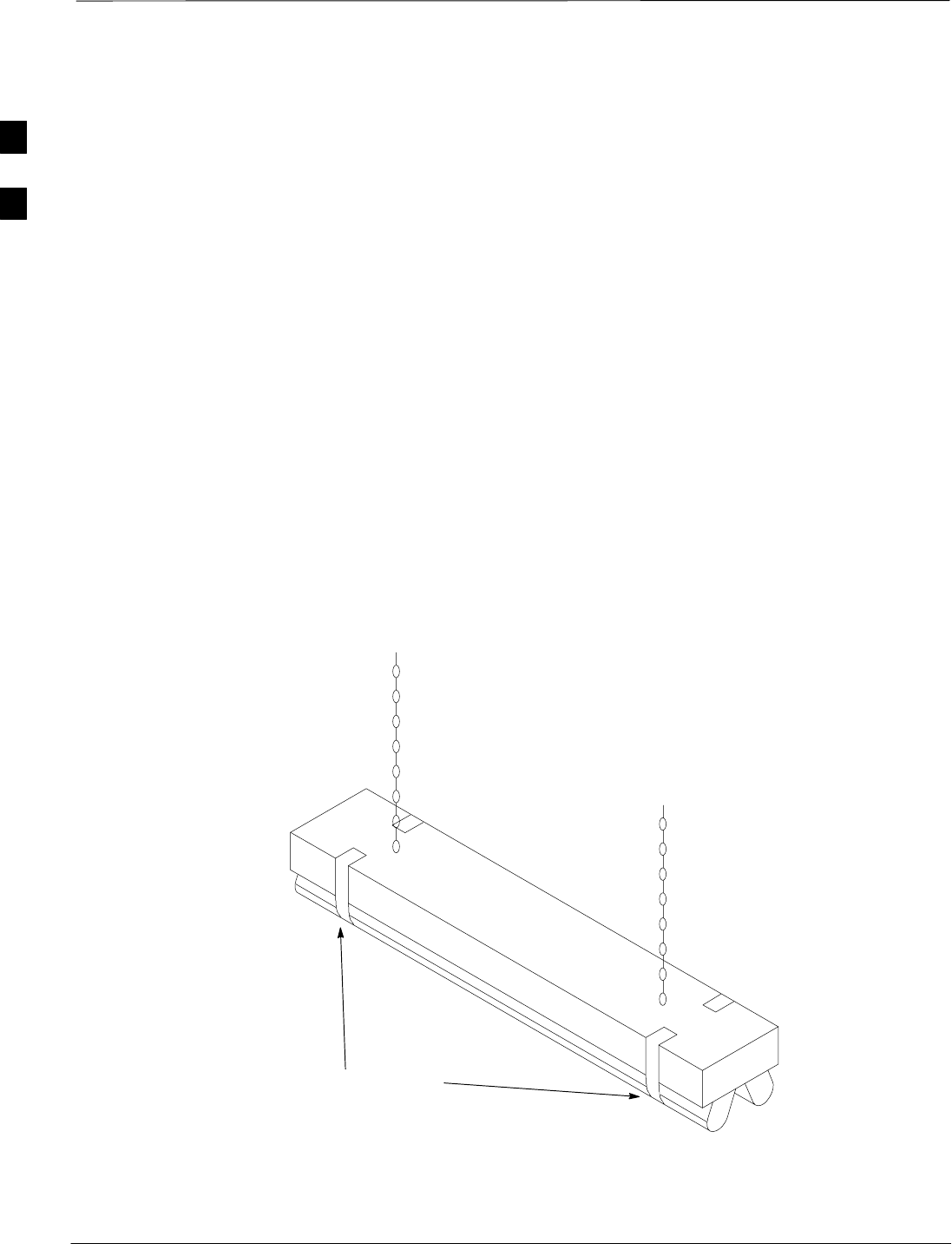
Prepare Site for the Arrival of the Equipment
DRAFT
SCt300 1X BTS Hardware Installation, ATP, and FRU Procedures JAN 2002
2-6
Description
This information covers various topics not all of which are needed at
every site. Based on the site characteristics execute the steps that apply
to your site. Before installing the equipment, do the following to ensure
the safety of installation personnel and to protect the equipment.
Equipment Arrival
Before the equipment arrives, indicate to the transport company an area
at the site where the equipment can be unloaded and, if necessary,
unpacked. The equipment should be carefully delivered to the site, along
with all equipment dollies and padding required to safely move the
equipment from the unloading area to the cell site. The following should
also be provided, outdoor weather protection, temporary lighting and
power for lighting and power tools.
Securing Fluorescent Lights
Figure 2-1 illustrates the use of tape to secure fluorescent tubes. Secure
any fluorescent tubes that may be hit or damaged by any unit, cable, or
personnel.
Figure 2-1: Securing Lights with Tape
Apply masking tape to keep
fluorescent tubes in place in
the fixtures. 0150–O_IL.doc
2

Prepare Site for the Arrival of the Equipment – continued
JAN 2002 2-7
SCt300 1X BTS Hardware Installation, ATP, and FRU Procedures
DRAFT
Procedure to Prepare the Site
for the Equipment
Table 2-1: Procedure to Prepare the Site for the BTS
Step Action
1If some type of protective padding is available install it around any existing equipment at the site
that could be damaged during installation of the units.
2Hang plastic sheets around intended work areas to prevent dust and debris from damaging
co-located equipment during installation.
3Secure any fluorescent tubes in place using masking tape. (Refer to Figure 2-1.)
NOTE
This will prevent the tubes from being inadvertently jarred from the fixtures during the
installation of equipment or cables.
4Locate the demarcation blocks for external utilities.
Verify that they are shown on the Site Engineering documents, and determine the required cable
routing back to the equipment frames.
5Verify the following:
SDC power is available and meets the site documentation specifications (if applicable).
SAC power is available and meets the site documentation specifications (if applicable).
SCable rack is installed per site document specifications.
SOutdoor cable runs are installed and meet local building codes.
SSpan line termination tie points are available.
SCustomer input termination tie points are available.
SPhone tie-in points (modem) are available.
SPhone access is available (if applicable).
SThere is clear access to move the equipment to the desired mounting area.
SThere is sufficient space for installation and service access to the equipment.
SCustomer supplied shelters are installed.
2

Dimensions and Clearances
DRAFT
SCt300 1X BTS Hardware Installation, ATP, and FRU Procedures JAN 2002
2-8
Overview
This information covers the dimensions and clearances associated with
the MicroCell and Primary Surge Suppressor units.
Dimensions and Clearances
Table 2-2, Table 2-3, Figure 2-2 through Figure 2–7 show the installed
dimensions and recommended clearances for each item.
Table 2-2: Installation Dimensions for the MicroCell and Primary Surge Suppressor Units
Item Height Width Depth Weight
MicroCell
(fully installed) 730 mm
28.76 in. 590 mm
23.25 in. 254 mm
10.01 in. 38.5 kg
84.7 lbs
MicroCell
(unit only) 590 mm
23.22 in. 450 mm
17.71 in. 150 mm
5.90 in. 24 kg
52.8 lbs
Primary Surge
Suppressor
(fully installed)
730 mm
28.76 in. 590 mm
23.25 in. 254 mm
10.01 in. 19.17 kg
42.26 lbs
Primary Surge
Suppressor
(unit only)
510 mm
20.08 in. 465 mm
18.32 in. 125 mm
4.93 in. 11 kg
24.26 lbs
Table 2-3 Minimum Clearances for MicroCell
Item Front Back Left Right Top Bottom
Installation and
Maintenance
Requirements
600 mm
23.62 in. 0100 mm
3.93 in. 200 mm
7.87 in. 0 0
Functional
Requirements
(with solar cover)
0 0 100 mm
3.93 in. 200 mm 50 mm
1.96 in.* 50 mm
1.96 in.*
Functional
Requirements
(without solar
cover)
50 mm
1.96 in. 0200 mm
7.87 in. 200 mm
7.87 in. 50 mm
1.96 in. 50 mm
1.96 in.
* Within these boundaries, area must remain 25% unobstructed. This is the open surface area at any cross
section. See Figure 2-7.
2

Dimensions and Clearances – continued
JAN 2002 2-9
SCt300 1X BTS Hardware Installation, ATP, and FRU Procedures
DRAFT
Table 2-4 Minimum Clearances for Surge Suppressor
Vertical Mounting
Item Front Back Left Right Top Bottom
Installation and
Maintenance
Requirements
600 mm
23.62 in. 0200 mm
7.87 in. 200 mm
7.87 in. 0 0
Functional
Requirements
(without solar
cover)
0 0 100 mm
3.93 in. 100 mm
3.93 in. 0 0
Functional
Requirements
(with solar cover)
0 0 0 0 0 0
2
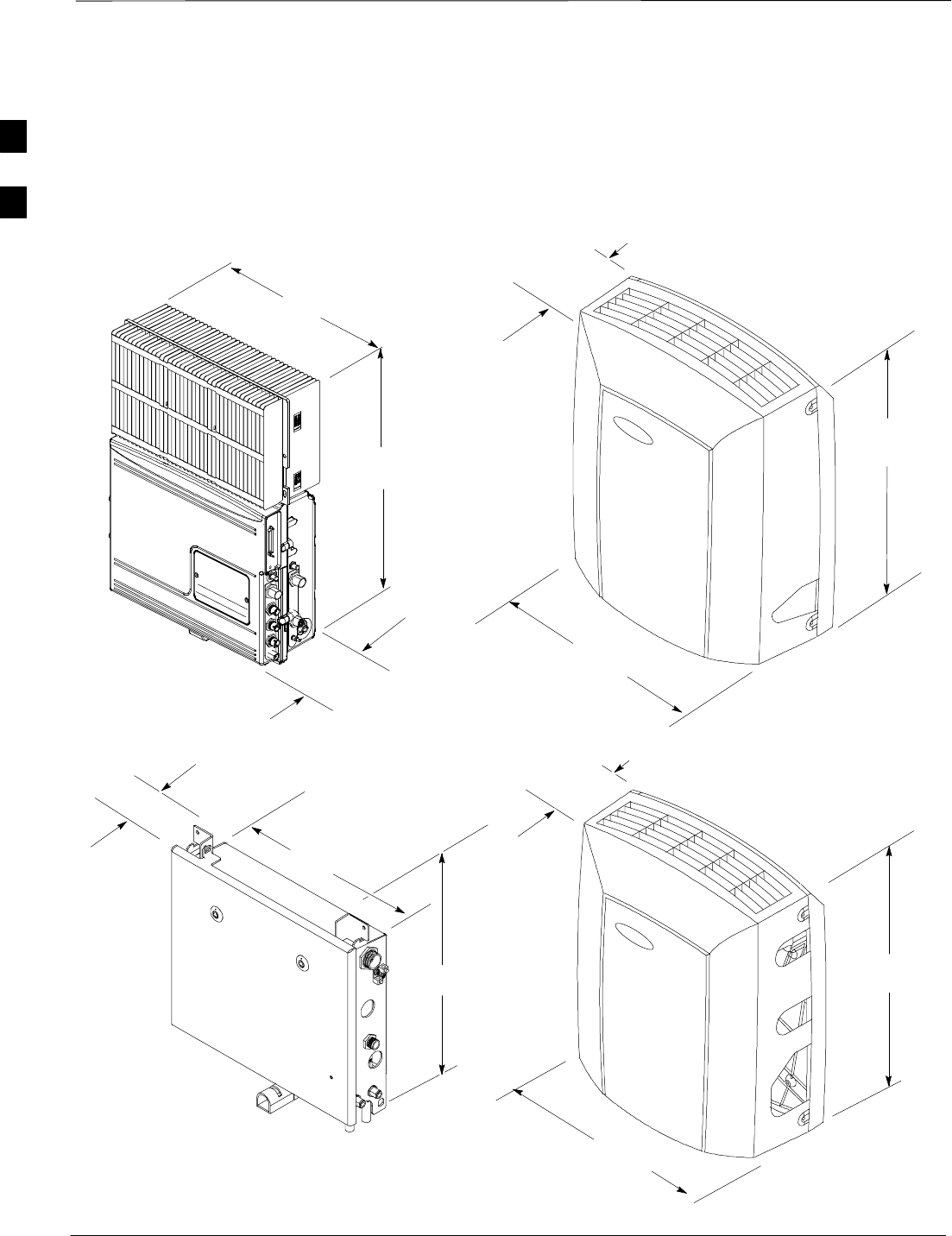
Dimensions and Clearances – continued
DRAFT
SCt300 1X BTS Hardware Installation, ATP, and FRU Procedures JAN 2002
2-10
Unit Dimensions
The unit dimensions are shown below in Figure 2-2.
Figure 2-2: Overall Dimensions of MicroCell Unit and Primary Surge Suppressor
MicroCell Unit
730mm (28.76 in.)
590 mm (23.25 in.)
450mm (17.71in.)
590mm (23.22in.)
150mm (5.90in.)
254 mm (10.01 in.)
465 mm (18.32 in.)
510 mm (20.08 in)
590 mm (23.25 in.)
254 mm
(10.01 in.)
With Solar Cover
Without Solar Cover
730mm (28.76 in.)
Primary Surge Suppressor
Without Solar Cover With Solar Cover
2
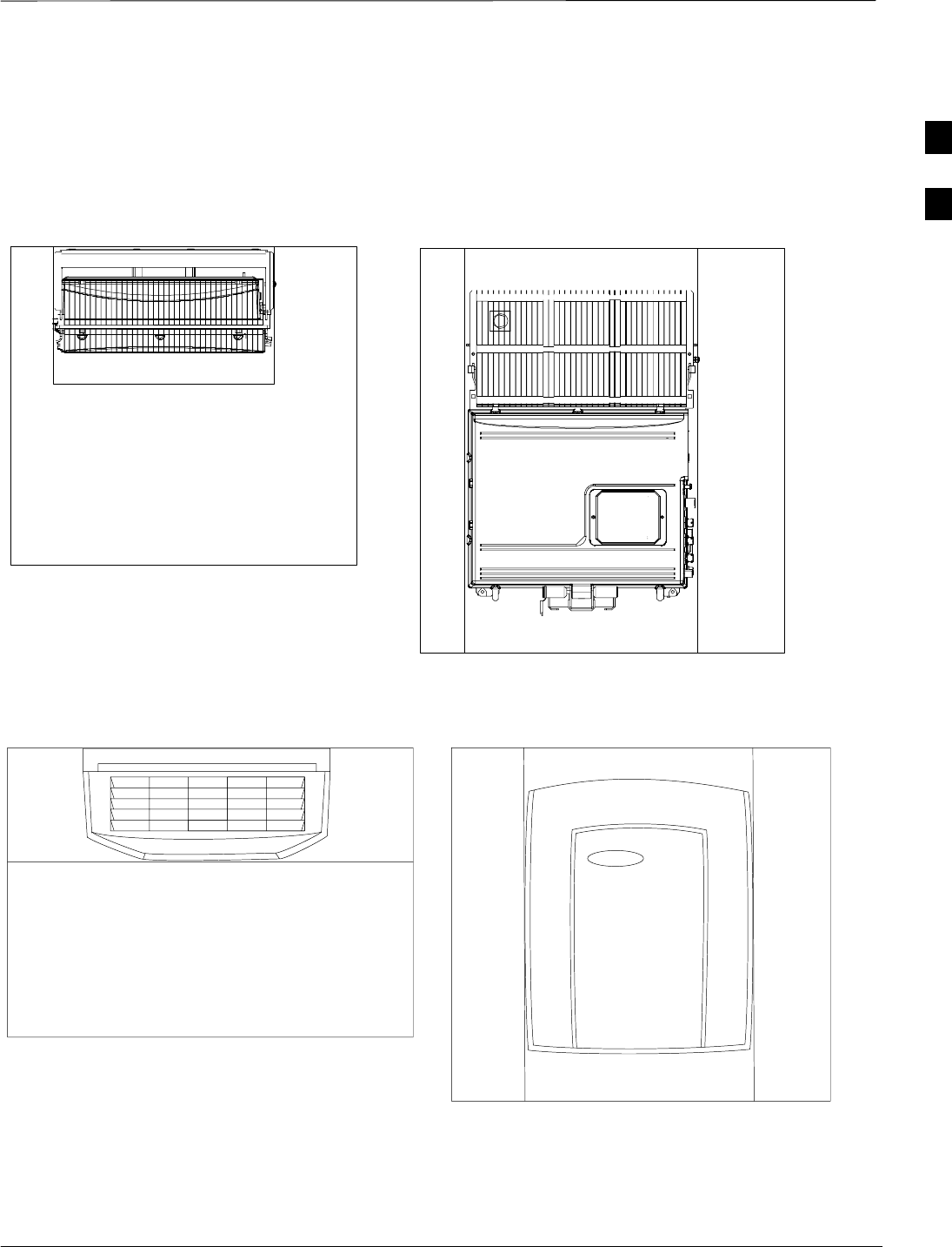
Dimensions and Clearances – continued
JAN 2002 2-11
SCt300 1X BTS Hardware Installation, ATP, and FRU Procedures
DRAFT
Unit Clearances
The unit clearances are shown below in Figure 2-3 through Figure 2-7.
Figure 2-3: Installation and Functional Clearances for MicroCell Units (Without Solar Covers)
50 mm air exhaust area
100 mm clearance for installation handles
200 mm clearance for tool access
50 mm air intake area
50 mm air intake area
600 mm from front of unit for FRU
installation and removal
Figure 2-4: Installation and Functional Clearances for MicroCell Units (With Solar Covers)
50 mm air exhaust area
50 mm air intake area
100 mm clearance for installation handles
200 mm clearance for tool access
600 mm from front of unit for FRU installation and removal
0 mm Functional Clearance in Front of
Microcell With Solar Cover
2
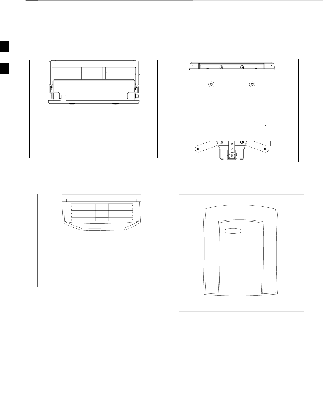
Dimensions and Clearances – continued
DRAFT
SCt300 1X BTS Hardware Installation, ATP, and FRU Procedures JAN 2002
2-12
Figure 2-5: Installation and Functional Clearances for Primary Surge Suppressor (without Solar Covers)
200 mm clearance for tool access
600 mm from front of unit for unit installation and removal
200 mm clearance for tool access
Figure 2-6: Installation and Functional Clearances for Primary Surge Suppressor (with Solar Covers)
200 mm clearance for tool access
600 mm from front of unit for FRU installation and removal
200 mm clearance for tool access
2
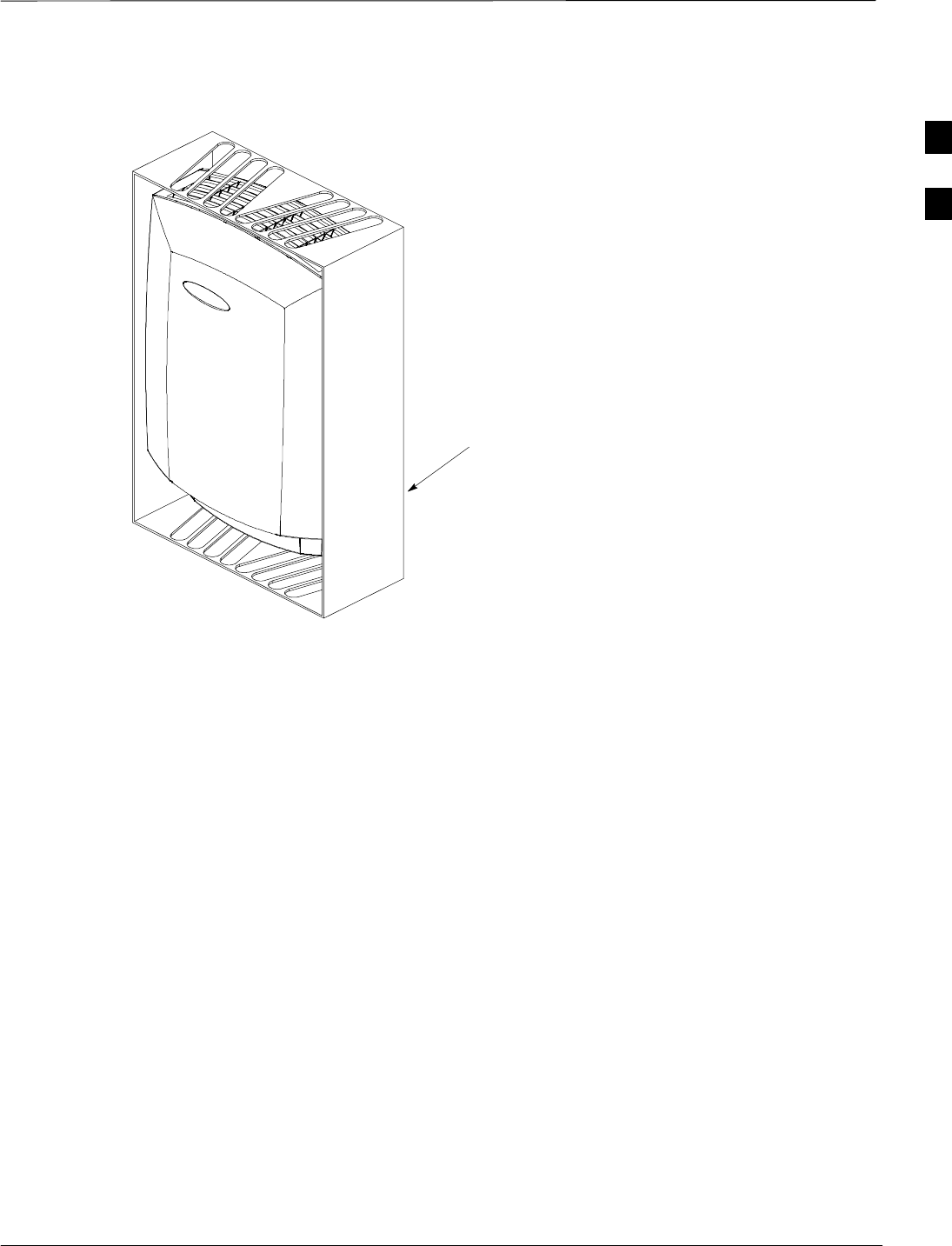
Dimensions and Clearances – continued
JAN 2002 2-13
SCt300 1X BTS Hardware Installation, ATP, and FRU Procedures
DRAFT
Figure 2-7: Concept of Functionality Clearances for MicroCell Units (V–Style Solar Cover)
THIS ILLUSTRATION SHOWS THE CONCEPT OF HOW
THE AREA ABOVE AND BELOW THE SCt300 BTS
SHOULD BE AT LEAST 25% UNOBSTRUCTED. THERE
IS NO BOX AROUND THE UNIT. BOX IS USED FOR
ILLUSTRATION PURPOSES ONLY
2

Dimensions and Clearances – continued
DRAFT
SCt300 1X BTS Hardware Installation, ATP, and FRU Procedures JAN 2002
2-14
Notes
2

JAN 2002 SCt300 1X BTS Hardware Installation, ATP, and FRU Procedures
DRAFT
Chapter 3: Installing Mounting Bracket and Remote GPS
Table of Contents
Mounting Bracket Installation Overview 3-1. . . . . . . . . . . . . . . . . . . . . . . . . . . . . .
Overview 3-1. . . . . . . . . . . . . . . . . . . . . . . . . . . . . . . . . . . . . . . . . . . . . . . .
Procedure Order 3-1. . . . . . . . . . . . . . . . . . . . . . . . . . . . . . . . . . . . . . . . . . .
Unpacking the Equipment and Inspecting for Damage 3-2. . . . . . . . . . . . . . . . . . .
Objective 3-2. . . . . . . . . . . . . . . . . . . . . . . . . . . . . . . . . . . . . . . . . . . . . . . .
How System is Packed 3-2. . . . . . . . . . . . . . . . . . . . . . . . . . . . . . . . . . . . .
Inspecting for Damage 3-2. . . . . . . . . . . . . . . . . . . . . . . . . . . . . . . . . . . . . .
Attaching the Mounting Bracket to a Wall 3-4. . . . . . . . . . . . . . . . . . . . . . . . . . . . .
Objective 3-4. . . . . . . . . . . . . . . . . . . . . . . . . . . . . . . . . . . . . . . . . . . . . . . .
Required Tools and Materials 3-4. . . . . . . . . . . . . . . . . . . . . . . . . . . . . . . .
Procedure to Drill Holes in the Wall 3-5. . . . . . . . . . . . . . . . . . . . . . . . . . .
Procedure to Secure the Mounting Bracket to a Wall 3-6. . . . . . . . . . . . . .
Mounting Bracket Hole Locations 3-7. . . . . . . . . . . . . . . . . . . . . . . . . . . . .
Attaching the Mounting Bracket to a Pole 3-9. . . . . . . . . . . . . . . . . . . . . . . . . . . . .
Objective 3-9. . . . . . . . . . . . . . . . . . . . . . . . . . . . . . . . . . . . . . . . . . . . . . . .
Required Tools and Materials 3-9. . . . . . . . . . . . . . . . . . . . . . . . . . . . . . . .
Procedure to Attach the Mounting Bracket to a Pole 3-10. . . . . . . . . . . . . .
Attaching the Mounting Bracket to a Rack 3-13. . . . . . . . . . . . . . . . . . . . . . . . . . . .
Objective 3-13. . . . . . . . . . . . . . . . . . . . . . . . . . . . . . . . . . . . . . . . . . . . . . . .
Required Tools and Materials 3-13. . . . . . . . . . . . . . . . . . . . . . . . . . . . . . . .
Procedure to Attach the Mounting Bracket to a Rack 3-13. . . . . . . . . . . . . .
Attaching Back Solar Cover to Mounting Bracket 3-15. . . . . . . . . . . . . . . . . . . . . . .
Objective 3-15. . . . . . . . . . . . . . . . . . . . . . . . . . . . . . . . . . . . . . . . . . . . . . . .
When to Use the Cover 3-15. . . . . . . . . . . . . . . . . . . . . . . . . . . . . . . . . . . . .
Required Tools and Materials 3-15. . . . . . . . . . . . . . . . . . . . . . . . . . . . . . . .
Procedure 3-15. . . . . . . . . . . . . . . . . . . . . . . . . . . . . . . . . . . . . . . . . . . . . . . .
Remote GPS Head Installation 3-16. . . . . . . . . . . . . . . . . . . . . . . . . . . . . . . . . . . . . .
Objective 3-16. . . . . . . . . . . . . . . . . . . . . . . . . . . . . . . . . . . . . . . . . . . . . . . .
Required Tools and Materials 3-16. . . . . . . . . . . . . . . . . . . . . . . . . . . . . . . .
RGPS Mounting Considerations 3-16. . . . . . . . . . . . . . . . . . . . . . . . . . . . . .
Procedure to Install the RGPS Head 3-17. . . . . . . . . . . . . . . . . . . . . . . . . . .
3

Table of Contents – continued
DRAFT
SCt300 1X BTS Hardware Installation, ATP, and FRU Procedures JAN 2002
Notes
3

Mounting Bracket Installation Overview
JAN 2002 3-1
SCt300 1X BTS Hardware Installation, ATP, and FRU Procedures
DRAFT
Overview
This chapter provides the information and procedures to:
SUnpack the equipment and inspect for damage.
SInstall rack or pole adapters.
SInstall the mounting bracket on a wall, pole, or rack.
SAttach the unit and covers to the mounting bracket.
Procedure Order
The process of installing the mounting bracket and Remote GPS receiver
requires that the following procedures be completed in the order shown.
1. Unpack the equipment and inspect for damage.
2. Install the mounting hardware on a wall, rack, or pole.
3. Attach the back solar cover.
4. Install the Remote GPS head.
3

Unpacking the Equipment and Inspecting for Damage
DRAFT
SCt300 1X BTS Hardware Installation, ATP, and FRU Procedures JAN 2002
3-2
Objective
The objective of this procedure is to unpack the equipment and inspect it
for damage.
How System is Packed
A unit is shipped in two boxes. Box 1 contains site installation specific
components and box 2 contains the unit itself. All of the following are
shipped in box 1.
Box 1
SSolar or fin covers
SUniversal mounting bracket
SRack mounting adapters and hardware
SPole mounting adapters and hardware
SExternal cables (AC input, DC input and SU)
SLower pin
SSite I/O junction box and cable assembly
STerminations
SAC Installation Box (required for outdoor applications)
Box 2
SMicrocell unit
Box 3 (Optional)
SPrimary Surge Suppressor
SSolar covers
SMounting bracket
SRack mounting adapters and hardware
SPole mounting adapters and hardware
SGround cables
The following are shipped separately:
SShort duration battery (optional) (Kit T392AA)
SRemote GPS receiver (optional)
Inspecting for Damage
Before installing any equipment, inspect it for damage. Report any
damage found to the Site Manager.
Only remove the equipment from the shipping containers when you are
ready to install.
3

Unpacking the Equipment and Inspecting for Damage – continued
JAN 2002 3-3
SCt300 1X BTS Hardware Installation, ATP, and FRU Procedures
DRAFT
Inspect items for:
Sdents
Sscratches
Sbent pins in connectors
Ssquareness of bracket
Sdamage to heatsink fins
Sisolating pads, washers on mounting bracket
Sfrayed cabling or chafed connectors 3
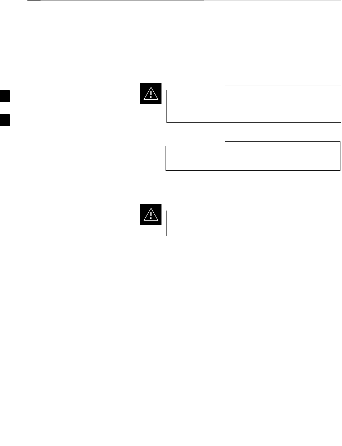
Attaching the Mounting Bracket to a Wall
DRAFT
SCt300 1X BTS Hardware Installation, ATP, and FRU Procedures JAN 2002
3-4
Objective
The objective of this procedure is to attach the mounting bracket on a
concrete wall.
For all applications always consult a licensed Civil
Engineer to determine the exact (Zone 3 and/or Zone 4)
compliance of your specific site.
CAUTION
If your site requires the optional Primary Surge Suppressor,
then you must install two mounting brackets.
NOTE
Required Tools and Materials
Do not use toggle bolts in sheet rock (dry wall). They will
not hold the system and they will damage the wall.
CAUTION
Due to the many types of walls that the BTS could potentially be
mounted to, it is impossible to detail all types in the context of this
manual. For this reason, the installers must use good judgement and get
recommendations from qualified personnel regarding the type of
mounting bolts that are appropriate for the particular walls on which the
BTS will be mounted.
Concrete wall
The following tools and materials in Table 3-1 are required to properly
and safely install the the mounting bracket on a concrete wall.
3
Attaching the Mounting Bracket to a Wall – continued
JAN 2002 3-5
SCt300 1X BTS Hardware Installation, ATP, and FRU Procedures
DRAFT
Table 3-1: Required Tools and Materials for Concrete Wall Mounting
Hand Tools Materials Power Tools
T30 Torx tamper bit, 1/4–in hex metal shim material Hilti wall drilling rig
Torque driver wrench, 1/4–in hex
female drive, 0–10 N–MHilti anchors (for each
bracket) Hilti DCM 18–14 metric bit
15/16-in. (23.8 mm) socket, a ratchet
wrench, and an 18-in. (45.7 cm)
breaker bar
MicroCell Mounting Kit shop vacuum
safety glasses electrical tape
chalk for marking outline on wall
tape measure
4-ft (1.22 m) bubble level
rubber mallet
ear plugs
dust mask
Procedure to Drill Holes in the
Wall
Safety glasses, dust masks, and ear plugs must be worn by
all installation personnel, including those in the immediate
vicinity of the personnel operating the drilling equipment.
WARNING
Table 3-2: Procedure to Drill Holes in the Wall for Mounting Bracket Installation
Step Action
1Verify with the site manager that the wall has been previously checked and is capable of
supporting the weight of the system.
2Hold the bracket in position and mark the mounting hole locations.
3Prepare a standard 3/8” electric drill or the Hilti wall drilling rig.
4Install the appropriate bit in the drill using the following information:
SFor concrete walls use the Hilti DCM 18–14 metric bit and Hilti anchors.
5Begin to drill by using short bursts until the bit has a “bite” into the wall.
6Run the drill at full speed to the appropriate depth. Check the depth of the hole by using the shop
vacuum to collect the debris.
* IMPORTANT
For concrete installation, the hole MUST be at least 5 in. (12.7 cm) deep. Anchors can not be
removed once they are tapped into the hole.
. . . continued on next page
3

Attaching the Mounting Bracket to a Wall – continued
DRAFT
SCt300 1X BTS Hardware Installation, ATP, and FRU Procedures JAN 2002
3-6
Table 3-2: Procedure to Drill Holes in the Wall for Mounting Bracket Installation
Step Action
7Repeat steps 5 through 6 for each mounting hole.
8Proceed to the “Procedure to Secure the Mounting Bracket to a Wall”, Table 3-3.
Procedure to Secure the
Mounting Bracket to a Wall
Refer to Figure 3-1 and Figure 3-2 and follow the procedure in Table 3-3
to secure the mounting bracket to a wall.
Table 3-3: Procedure to Secure the Mounting Bracket to a Wall
Step Action
* IMPORTANT
Use the shoulder washers attached to the mounting bracket in each mounting hole to electrically
isolate the mounting bracket from the wall.
1Insert a Hilti anchor into each mounting hole. Tap each anchor using a rubber mallet until each
anchor is completely seated in a hole.
2Position the mounting bracket on the wall over the mounting holes. Start, but do not tighten all
bolts.
! CAUTION
Only put shims under the bracket where the isolation pad is present. Do not place shims so that
they will contact the bare metal of the frame.
3Place a 4-ft (1.22 m) level on the bracket from top-to-bottom. Then, using metal shim material,
level the bracket.
4Use a 15/16-in. (23.8 mm) socket, a ratchet wrench, and an 18-in. (45.7 cm) breaker bar, to
tighten the red cap of each anchor bolt until the red cap shears off.
NOTE
When the red cap shears off, the anchor bolt has been tightened to the correct torque.
3
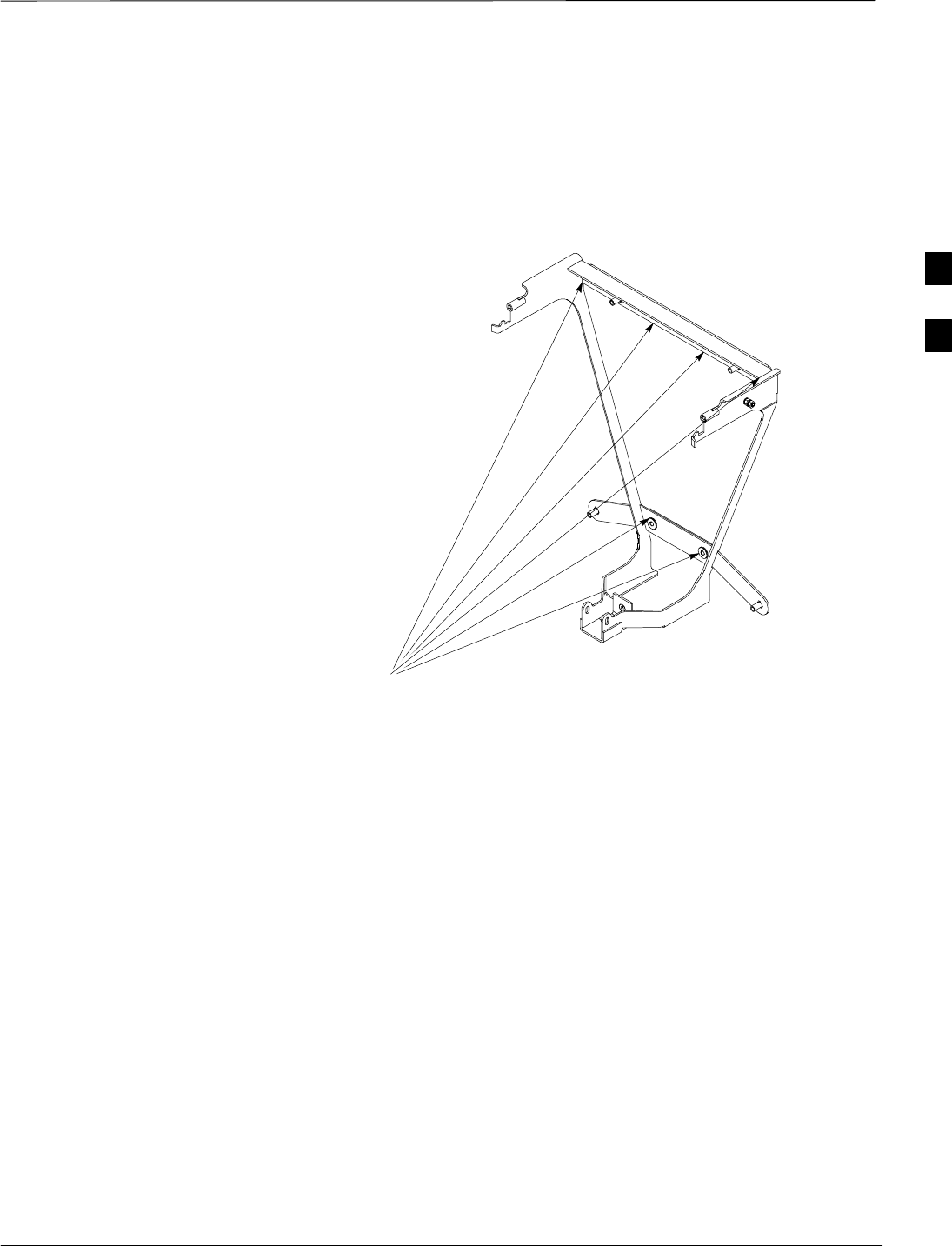
Attaching the Mounting Bracket to a Wall – continued
JAN 2002 3-7
SCt300 1X BTS Hardware Installation, ATP, and FRU Procedures
DRAFT
Mounting Bracket Hole
Locations
Figure 3-1 and Figure 3-2 show the holes to use to attach the mounting
bracket to a wall.
Figure 3-1: Holes to Use to Mount the Bracket to the Wall
HOLES FOR BRACKET MOUNTING
3
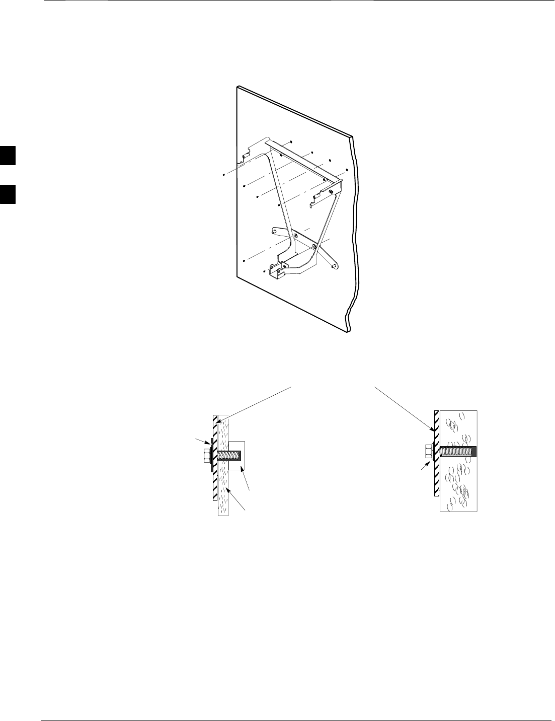
Attaching the Mounting Bracket to a Wall – continued
DRAFT
SCt300 1X BTS Hardware Installation, ATP, and FRU Procedures JAN 2002
3-8
Figure 3-2: Securing Mounting Bracket to a Wall
(FROM TOP TO BOTTOM)
BOLT AND PLASTIC
SHOULDER WASHER
THREADED INTO
ANCHOR THROUGH
MOUNTING BRACKET
(FROM TOP TO BOTTOM)
LAG SCREW, AND PLASTIC
SHOULDER WASHER
THREADED INTO PILOT
HOLE THROUGH
MOUNTING PLATE.
BRACKET
(FOR CLARITY, THE
REST OF THE
BRACKET IS NOT
SHOWN)
LAG SCREW CONCRETE ANCHOR
STUD
WALL
PLACE SCREW THROUGH HOLES
3
Attaching the Mounting Bracket to a Pole
JAN 2002 3-9
SCt300 1X BTS Hardware Installation, ATP, and FRU Procedures
DRAFT
Objective
The objective of this procedure is to attach the mounting bracket to a
pole.
The mounting pole structure must be reviewed for its
ability to support the weight of the MicroCell [38.5 kg
(84.7 lbs.)] and Primary Surge Suppressor [19.17 kg (42.26
lbs.)] under high winds, earthquakes, etc.
SInstalling the BTS on an inadequate pole may result in
serious personal injury even death or damage to the
equipment.
SPlacement of the BTS should not present a hazard to
pedestrians by impeding passage, nor to field service
personnel by being placed near high voltage or other
hazardous conditions.
SAll cabling must be constrained in or on the pole in
accordance to local building codes.
WARNING
For all applications always consult a licensed Civil
Engineer to determine the exact (Zone 3 and/or Zone 4)
compliance of your specific site.
CAUTION
Required Tools and Materials
The following tools and materials are required to properly and safely
install the mounting bracket to a pole.
Table 3-4: Required Tools and Materials for Pole Mounting
Hand Tools Materials Power Tools
Safety Glasses MicroCell Mounting Kit No Power Tools Required
Bucklestrap Cutting Tool (Motorola
part number 6604809N01) electrical tape
(customer supplied)
T30 Torx tamper bit, 1/4–in. hex
Torque driver wrench, 1/4–in. hex
female drive, 0–10 N–M
Ball Peen (Metal Working) Hammer
Heavy Gloves
Tape Measure
3

Attaching the Mounting Bracket to a Pole – continued
DRAFT
SCt300 1X BTS Hardware Installation, ATP, and FRU Procedures JAN 2002
3-10
Procedure to Attach the
Mounting Bracket to a Pole
Follow the procedure in Table 3-5 to attach the mounting bracket to a
pole.
Table 3-5: Procedure to Attach the Mounting Bracket to a Pole
Step Action
1Verify that the isolator pads are in place on the bracket.
5Verify the safety of the installation location.
6Place the bucklestrap through the channel clamp as shown in Figure 3-3.
7Place the channel clamp and bucklestrap on the pole approximately where the upper portion of the
BTS is to be located. See Figure 3-3.
8Slide and center the upper channel extrusion on the channel clamp. See Figure 3-3.
9Wrap the bucklestrap around the pole and through the fitting on the end of the band. Pull the
band until it is makes concentric contact with the pole.
10 Start but do not tighten the lower channel extrusion to the mounting bracket. Use 2 M6x19
tamper–resistant screws.
11 Before you tighten the lower strap, attach the mounting bracket to the top channel extrusion.
12 Slide the bucklestrap through the channel clamp and slide the channel clamp on the lower channel
extrusion. Wrap the bucklestrap around the pole and through the fitting.
13 Secure the bucklestrap with the bucklestrap tool. Refer to the instructions included with the
bucklestrap tool.
14 Use a T30 Torx tamper bit to tighten the six M6x19 screws to 5.0 N–m.
15 Center the channel clamp on to the lower extrusion.
16 Place the bucklestrap through the lower channel clamp.
17 Use the bucklestrap tool to secure the lower strap.
3
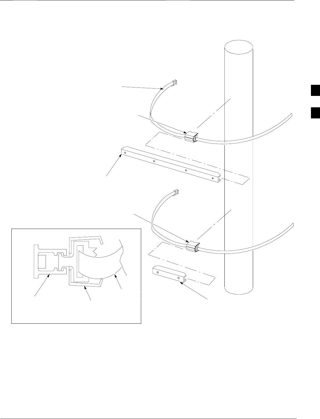
Attaching the Mounting Bracket to a Pole – continued
JAN 2002 3-11
SCt300 1X BTS Hardware Installation, ATP, and FRU Procedures
DRAFT
Figure 3-3: Pole Adapter and Straps
CHANNEL CLAMP
UPPER CHANNEL EXTRUSION
PART NUMBER 0709991S02
LOWER CHANNEL EXTRUSION
PART NUMBER 0709991S03
CHANNEL CLAMP
PART NUMBER 4209992S01
SIDE VIEW OF CHANNEL CLAMP AND BAND
CHANNEL CLAMP
PART NUMBER 4209992S01
BUCKLESTRAP
PART NUMBER 4209993S04
0159–O_IL.doc
CHANNEL
EXTRUSION
BUCKLESTRAP
3
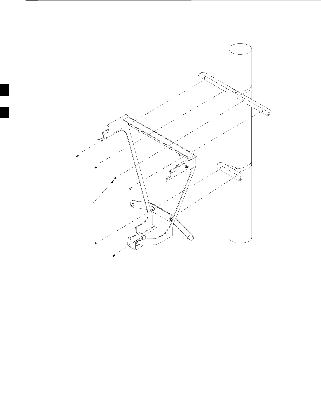
Attaching the Mounting Bracket to a Pole – continued
DRAFT
SCt300 1X BTS Hardware Installation, ATP, and FRU Procedures JAN 2002
3-12
Figure 3-4: Attaching Mounting Bracket to a Pole
M6x19 SCREWS
PART NUMBER 0387541C03
3

Attaching the Mounting Bracket to a Rack
JAN 2002 3-13
SCt300 1X BTS Hardware Installation, ATP, and FRU Procedures
DRAFT
Objective
The objective of this procedure is to attach the mounting bracket to a
19-in. rack.
Rack must conform to EIA–RS–310–C or JIS–C–6010 standards.
Required Tools and Materials
The following tools and materials are required to properly and safely
install the mounting bracket on a rack.
Table 3-6: Required Tools and Materials for Rack Mounting
Hand Tools Materials Power Tools
Torque driver wrench, 1/4–in. hex
female drive, 0–10 N–MMicroCell Mounting Kit No Power Tools Required
T30 Torx tamper bit, 1/4–in. hex Four machine screws 12–24
5/8-in. self tapping (customer
supplied)
Chalk or marker to mark
location on rack
electrical tape
(customer supplied)
Procedure to Attach the
Mounting Bracket to a Rack
To attach the mounting bracket to a rack follow the procedure in
Table 3-7.
Table 3-7: Procedure to Attach the Mounting Bracket to a Rack
Step Action
1Verify that isolating pads and washers are installed in the bracket. If not, contact the site manager.
2Use the mounting bracket as a guide to mark the holes in the rack to be used to mount the upper
adapter.
3Use two self–tapping machine screws (customer supplied) to attach the upper rack adapter
(Motorola part number 0709994S01) to the rack.
4Use a T30 Torx tamper bit and two M6x19 screws to attach but do not tighten the lower rack
adapter to the mounting bracket.
5Use a T30 Torx tamper bit and four M6x19 screws to attach the mounting bracket to the upper
rack adapter. Do not tighten.
6Use two machine screws (customer supplied) to attach the lower rack adapter to the rack.
7Use a T30 Torx tamper bit to torque the screws connecting the mounting bracket to the upper and
lower adapters. Torque to 5.0 N–M.
3
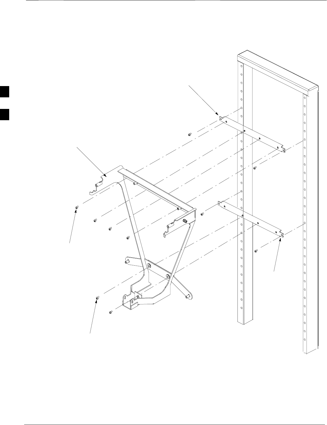
Attaching the Mounting Bracket to a Rack – continued
DRAFT
SCt300 1X BTS Hardware Installation, ATP, and FRU Procedures JAN 2002
3-14
Figure 3-5: Attaching the Mounting Bracket to a Rack
A=MACHINE SCREW 12–24 5/8 IN.
(CUSTOMER SUPPLIED)
RACK ADAPTER
PART NUMBER 0709994S01
RACK ADAPTER
PART NUMBER
0709994S01
M6 x19 SCREW (4)
M6 x 19 SCREW (2)
A
A
A
A
MOUNTING BRACKET
PART NUMBER 0709994S01 OR S02
3
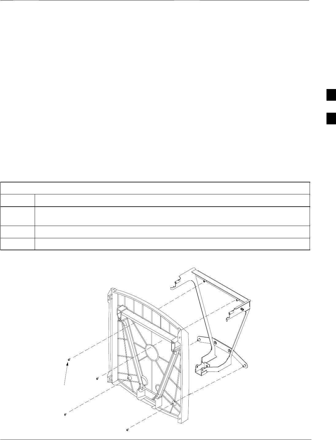
Attaching Back Solar Cover to Mounting Bracket
JAN 2002 3-15
SCt300 1X BTS Hardware Installation, ATP, and FRU Procedures
DRAFT
Objective
The objective of this procedure is to attach the back solar cover to the
mounting bracket.
When to Use the Cover
Solar Covers are required in all outdoor applications
Required Tools and Materials
The following tools are required to attach the back solar cover to the
mounting bracket.
STorque driver wrench, 1/4–in. hex female drive, 0–10 N–M
ST30 Torx bit
Procedure
Attach the back solar cover to the mounting bracket by following the
procedure in Table 3-8 and the information in Figure 3-6.
Table 3-8: Procedure to Attach Back Solar Cover to Mounting Bracket
Step Action
1Place the back solar cover on the mounting bracket so the cooling vents are at the top. Align the
four M6 screws with the mounting holes.
2Using a T30 Torx bit, start but do not tighten all four M6 screws.
3Using the T30 Torx bit, tighten the four M6 screws to 5.0 N–m.
Figure 3-6: Attaching MicroCell Back Solar Cover to Mounting Bracket
M6 SCREWS
0309959S06
3

Remote GPS Head Installation
DRAFT
SCt300 1X BTS Hardware Installation, ATP, and FRU Procedures JAN 2002
3-16
Objective
The objective of this procedure is to show how to install the Remote
Global Positioning System (RGPS) head.
Required Tools and Materials
One RGPS Head (Motorola Part Number 0186012H03) is required to do
this procedure.
RGPS Mounting
Considerations
The RGPS Head requires specific mounting considerations in order to
properly observe the GPS satellites.
SThe mounting pipe for the RGPS head should be mounted vertically
with less than five degrees (5_) of tilt.
SThe RGPS head mounting hardware which comes with the RGPS
head should be used in all installations. This mounting hardware
properly isolates the painted metal base of the RGPS head from other
conductive surfaces. If the metal base comes in contact with another
conductive surface, the electrical surge resistance of the RGPS head
can be significantly reduced leading to RGPS head failure.
–If the supplier of the RGPS mounting hardware cannot be used, the
installer MUST make certain that the metal base of the RGPS head
does not make contact with any conductive surface.
SPosition the RGPS head to have an unobstructed view of the sky and
to minimize the chance of debris (leaves, dirt, etc.) accumulating on
the radome of the RGPS head.
SThe RGPS head must have a clear view of the sky, preferably to
within ten degrees (10_) of the horizon in all directions. The total
blockage of the sky (due to buildings, mountains, etc.) should be less
than 50%.
SPlace the RGPS head as far away from the BTS transmit antenna as
possible to avoid RF interference issues.
SPlace the RGPS head at least 15 m away from lightning rods, towers,
or structures that attract lightning. RGPS head damage is usually not
the result of a direct lightning strike, but of a lightning strike on a
nearby structure. Also, since a lightning rod is connected to an earth
ground, it can act as a shield and create a shadow that may block or
reduce the signal from a satellite.
SAfter you power on the BTS, you can check the RGPS signal
strengths with the GPS_STATUS command on the MMI port.
–An optimal installation will have at least one satellite (SV) with an
RSSI value ≥ 50, and at least four (4) satellites with RSSI values ≥
45.
–A minimal installation should have at least four (4) satellites with
RSSI values ≥ 40.
3
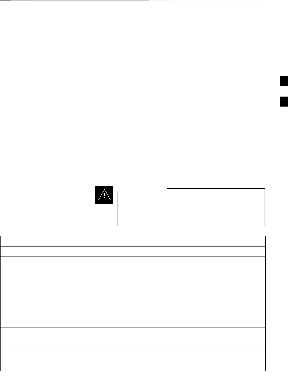
Remote GPS Head Installation – continued
JAN 2002 3-17
SCt300 1X BTS Hardware Installation, ATP, and FRU Procedures
DRAFT
SThe RGPS head is rated for ambient air temperatures from –40°C
(–40°F) to 80°C (176°F), and has ratings for humidity, shock,
waterproof, UV light resistance, vibrations, salt fog, ESD, EMI, and
altitude.
SIf you are designing a system to support a maximum of 12
daisy–chained BTS sites, the maximum cable length between the
RGPS head and the first BTS is 600m (1968 ft.). The maximum cable
length between each subsequent BTS in the chain is also 600m (1968
ft.). If a long cable run needs to be broken into pieces, minimize the
number of breaks in the cable.
SIf you are designing a system to support a maximum of 7
daisy–chained BTS sites, the maximum cable length between the
RGPS head and the first BTS is 1km (3280 ft.). The maximum cable
length between each subsequent BTS in the chain is also 1km (3280
ft). If a long cable run needs to be broken into pieces, minimize the
number of breaks in the cable.
Procedure to Install the RGPS
Head
Table 3-9, Figure 3-7, and Figure 3-8 show the procedure for installing
the RGPS head.
The RGPS head must not make contact with any metal
surface other than the provided hardware. Use only the
equipment provided to mount the RGPS head. Failure to
do so could damage the RGPS head.
CAUTION
Table 3-9: Procedure to Install the RGPS Head
Step Action
1Determine the mounting location.
2n WARNING
The structure of the wall should be verified by a qualified structural engineer.
Mounting the RGPS head and hardware to an inadequate wall structure and/or using inadequate
installment methods can result in serious personal injury.
Use the appropriate mounting bolts for the mounting surface and install the two wall mounting
brackets. Refer to Figure 3-7.
3Insert the RGPS cable (cable M) into the pipe.
4Connect the 12 pin Deutsch connector of the RGPS unit cable to cable M. Refer to Figure 3-8.
Tighten the spinning flange on the connector a quarter turn to secure the connection.
5Insert the pipe into the threaded mount in the RGPS unit and carefully hand–tighten.
6Place the assembly into the mounting brackets. Refer to Figure 3-7. Tighten the U–bolt clamps
to secure the assembly.
3
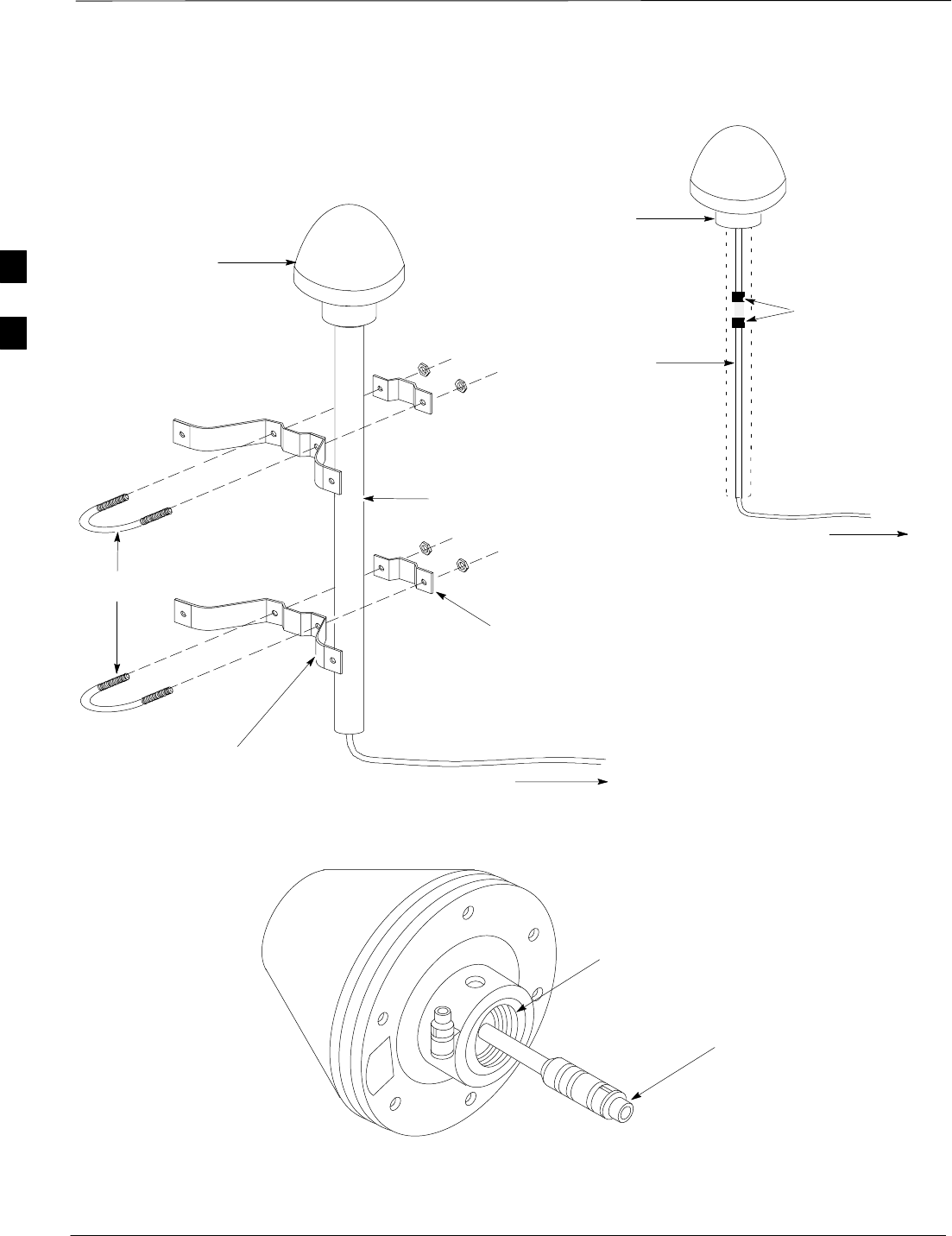
Remote GPS Head Installation – continued
DRAFT
SCt300 1X BTS Hardware Installation, ATP, and FRU Procedures JAN 2002
3-18
Figure 3-7: Installing the Remote GPS Head
WALL MOUNTING
BRACKETS (2)
CLAMP BRACKETS (2)
U–BOLTS
CABLE TO SITE I/O
INTERFACE (CABLE M)
REFER TO VIEW A
CABLE TO SITE
I/O INTERFACE
(CABLE M)
RGPS HEAD WITH
12 PIN MALE
CONNECTOR
MATING
CONNECTORS
RGPS INTERFACE
CABLE WITH 12 PIN
FEMALE CONNECTOR
ON ONE END AND
UNTERMINATED WIRE
ON OTHER END
VIEW A
RGPS HEAD
(MOTOROLA PART
NUMBER 0186012H03)
Figure 3-8: RGPS Head
THREADED MOUNT ADAPTER
12–PIN DEUTSCH TYPE MMP
CONNECTOR
3

JAN 2002 SCt300 1X BTS Hardware Installation, ATP, and FRU Procedures
DRAFT
Chapter 4: Preparing Site Cabling for Sites Equipped with
Customer–Supplied Site I/O Interface
Table of Contents
Cabling Overview 4-1. . . . . . . . . . . . . . . . . . . . . . . . . . . . . . . . . . . . . . . . . . . . . . . .
Overview 4-1. . . . . . . . . . . . . . . . . . . . . . . . . . . . . . . . . . . . . . . . . . . . . . . .
Configurations Supported 4-1. . . . . . . . . . . . . . . . . . . . . . . . . . . . . . . . . . .
Cabling Installation Order 4-1. . . . . . . . . . . . . . . . . . . . . . . . . . . . . . . . . . .
Cable Labels 4-1. . . . . . . . . . . . . . . . . . . . . . . . . . . . . . . . . . . . . . . . . . . . .
Cable Descriptions 4-2. . . . . . . . . . . . . . . . . . . . . . . . . . . . . . . . . . . . . . . . . . . . . . .
Cable Descriptions and Part Numbers 4-2. . . . . . . . . . . . . . . . . . . . . . . . . .
Motorola Kits for Multi–Unit Logical BTS Installations 4-3. . . . . . . . . . .
Motorola Kits for RGPS Cabling 4-5. . . . . . . . . . . . . . . . . . . . . . . . . . . . .
Site Cabling for BTS With Customer–Supplied Site I/O Interface 4-6. . . . . . . . . .
Preparing Site Cabling Scope of Work 4-6. . . . . . . . . . . . . . . . . . . . . . . . .
Power, Ground, and Battery Cabling for Sites Equipped with
Customer–Supplied Site I/O Interface 4-10. . . . . . . . . . . . . . . . . . . . . . . . . . . . . . . .
Objective 4-10. . . . . . . . . . . . . . . . . . . . . . . . . . . . . . . . . . . . . . . . . . . . . . . .
Other Grounding Considerations 4-10. . . . . . . . . . . . . . . . . . . . . . . . . . . . . .
Power Requirements and Configurations 4-10. . . . . . . . . . . . . . . . . . . . . . .
Required Cables 4-11. . . . . . . . . . . . . . . . . . . . . . . . . . . . . . . . . . . . . . . . . . .
AC Input Cable Information 4-11. . . . . . . . . . . . . . . . . . . . . . . . . . . . . . . . .
DC Input Cable Information 4-12. . . . . . . . . . . . . . . . . . . . . . . . . . . . . . . . .
Procedures to Install Earth Ground, AC/DC Power, and
Battery Cabling 4-12. . . . . . . . . . . . . . . . . . . . . . . . . . . . . . . . . . . . . . . . . . .
Antenna Cabling for Sites Equipped with Customer–Supplied Site
I/O Interface 4-15. . . . . . . . . . . . . . . . . . . . . . . . . . . . . . . . . . . . . . . . . . . . . . . . . . . .
Objective 4-15. . . . . . . . . . . . . . . . . . . . . . . . . . . . . . . . . . . . . . . . . . . . . . . .
Cable Labels 4-15. . . . . . . . . . . . . . . . . . . . . . . . . . . . . . . . . . . . . . . . . . . . .
Required Cables 4-15. . . . . . . . . . . . . . . . . . . . . . . . . . . . . . . . . . . . . . . . . . .
Antenna Cable Pin and Signal Information 4-15. . . . . . . . . . . . . . . . . . . . . .
Procedure to Install Antenna Cabling for One Microcell 4-15. . . . . . . . . . .
Procedure to Install Antenna Cabling for
Multi–Unit Logical BTS Sites 4-16. . . . . . . . . . . . . . . . . . . . . . . . . . . . . . . .
Site I/O , Span Line, RGPS and Modem Cabling for Sites Equipped with
Customer–Supplied Site I/O Interface 4-18. . . . . . . . . . . . . . . . . . . . . . . . . . . . . . . .
Objective 4-18. . . . . . . . . . . . . . . . . . . . . . . . . . . . . . . . . . . . . . . . . . . . . . . .
Cable Labels 4-18. . . . . . . . . . . . . . . . . . . . . . . . . . . . . . . . . . . . . . . . . . . . .
Required Cables 4-18. . . . . . . . . . . . . . . . . . . . . . . . . . . . . . . . . . . . . . . . . . .
Site I/O Cabling 4-18. . . . . . . . . . . . . . . . . . . . . . . . . . . . . . . . . . . . . . . . . . .
Procedure to Install Site I/O Cable Between Site I/O Junction Box and
Site I/O Interface 4-19. . . . . . . . . . . . . . . . . . . . . . . . . . . . . . . . . . . . . . . . . .
4

Table of Contents – continued
DRAFT
SCt300 1X BTS Hardware Installation, ATP, and FRU Procedures JAN 2002
Pin and Signal Information for Site I/O Cabling 4-20. . . . . . . . . . . . . . . . . .
Connecting Customer–Defined Inputs to the Site I/O Interface 4-22. . . . . .
Connecting the RGPS Cable to the Site I/O Interface 4-23. . . . . . . . . . . . . .
Connecting the Span Line Cable to the Site I/O Interface 4-23. . . . . . . . . .
Connecting a Phone Line to the Site I/O Interface (Modem Support) 4-23.
RGPS Cabling for Multiple BTS Sites 4-24. . . . . . . . . . . . . . . . . . . . . . . . . . . . . . . .
Objective 4-24. . . . . . . . . . . . . . . . . . . . . . . . . . . . . . . . . . . . . . . . . . . . . . . .
Background 4-24. . . . . . . . . . . . . . . . . . . . . . . . . . . . . . . . . . . . . . . . . . . . . .
Required Tools and Equipment 4-24. . . . . . . . . . . . . . . . . . . . . . . . . . . . . . .
Cable Diagrams and Description 4-25. . . . . . . . . . . . . . . . . . . . . . . . . . . . . .
Procedure to Install RGPS Cabling for an Indoor Installation 4-25. . . . . . .
Procedure to Install RGPS Cabling for an Outdoor Installation 4-26. . . . . .
Cable Connections 4-29. . . . . . . . . . . . . . . . . . . . . . . . . . . . . . . . . . . . . . . . .
Span Line Daisy Chain Cabling 4-32. . . . . . . . . . . . . . . . . . . . . . . . . . . . . . . . . . . . .
Objective 4-32. . . . . . . . . . . . . . . . . . . . . . . . . . . . . . . . . . . . . . . . . . . . . . . .
Background 4-32. . . . . . . . . . . . . . . . . . . . . . . . . . . . . . . . . . . . . . . . . . . . . .
Required Cables 4-32. . . . . . . . . . . . . . . . . . . . . . . . . . . . . . . . . . . . . . . . . . .
Procedure 4-32. . . . . . . . . . . . . . . . . . . . . . . . . . . . . . . . . . . . . . . . . . . . . . . .
Cable Connections 4-32. . . . . . . . . . . . . . . . . . . . . . . . . . . . . . . . . . . . . . . . .
4