Nokia Solutions and Networks T6CB1 SC300 1X Microcell @ 1.9 GHz User Manual 2 of 3
Nokia Solutions and Networks SC300 1X Microcell @ 1.9 GHz Users Manual 2 of 3
Contents
- 1. Users Manual 1 of 3
- 2. Users Manual 2 of 3
- 3. Users Manual 3 of 3
Users Manual 2 of 3

Cabling Overview
JAN 2002 4-1
SCt300 1X BTS Hardware Installation, ATP, and FRU Procedures
DRAFT
Overview
This chapter provides the procedures to prepare the BTS site cabling, but
not attach it to the unit. Chapter 6 shows the scope of work for unit
cabling.
You will connect cables to the site and route them to the BTS location.
You will attach the cables to the unit in Chapter 6.
Repeat cabling installation as necessary for each unit at the BTS.
Cabling is one of the most noticeable aspects of
workmanship. Straight runs and proper turns are critical for
a positive evaluation of the work.
NOTE
Configurations Supported
This chapter supports cable installation for single carrier omni
configurations and multi–carrier omni configurations. This chapter also
supports cable installations for sites equipped with the
customer–supplied Site I/O Interface. Chapter 5 supports installations
for sites equipped with the optional Primary Surge Suppressor.
Cabling Installation Order
To install the cables, Motorola recommends that the following
procedures be completed in the order shown:
1. Earth ground cabling
2. AC power cabling
3. DC power cabling
4. Battery cabling (optional)
5. Antenna cabling
6. Site I/O interface cabling
7. RGPS/HSO cabling (optional)
8. Span line daisy chain cabling (optional)
Cable Labels
The “Cable Descriptions and Part Numbers” in Table 4-1 provides cable
descriptions and part numbers. The labels used to designate the cables
(A, B, C, etc.) are used throughout this manual.
4

Cable Descriptions
DRAFT
SCt300 1X BTS Hardware Installation, ATP, and FRU Procedures JAN 2002
4-2
Cable Descriptions and Part
Numbers
Table 4-1 gives the cable descriptions and part numbers for the cables
used to install the BTS. The following cables are necessary for sites
equipped with the customer–supplied Site I/O Interface and the Primary
Surge Suppressor.
Table 4-1: Cable Descriptions and Part Numbers
Cable Qty. Part Number Description
A 1 3087701C02 Ground cable, 8 -AWG, insulated copper wire. Requires one ring lug
connector. Used for Primary Surge Suppressor Installation.
B 1–4 3087701C01 Ground cable. Installed between Site I/O Junction Box and Mounting
Bracket.
C 1–8 Customer
Supplied Antenna cable, 50–Ohm coaxial terminated with at least one male,
N–type connector.
D 2–6 Customer
Supplied Antenna cable, terminated with 2 male N–type connectors
E 1* 3087707C03 MIB A cable (current, 2m; micro) (part of kit T448H, T448G and
T448A)
F 1* 3087707C04 MIB B cable (current, 2m) (part of kit T448AR, T448AY, and T448H)
G 2* 3087707C05 MIB C cable (current, 2m) (part of kit T448H)
I 1* 3087707C07 MIB B cable (long, 5m) (part of kit T448AS, T448AZ, and T448G)
J 2* 3087707C08 MIB C cable (long, 5m) (part of kit T448G)
K 1* 3087707C09 MIB A cable (short, 1m; micro) (part of kit T448B)
L 1–4 3087701C04 Y–Ground cable (for Site I/O and external SU)
M 1 3086039H11 RGPS cable, 125 ft.
3086039H12 RGPS cable, 250 ft.
3086039H13 RGPS cable, 500 ft.
3086039H14 RGPS cable, 1000 ft.
3086039H15 RGPS cable, 2000 ft.
N 1 Customer
Supplied Span cable. 22–24 AWG solid copper twisted pair.
O 1 Customer
Supplied Customer Input cable. 22–24 AWG solid copper twisted pair.
P 1–4 3088120C03 SU RF cable
Q 1 –SU Digital Cable
. . . continued on next page
4

Cable Descriptions – continued
JAN 2002 4-3
SCt300 1X BTS Hardware Installation, ATP, and FRU Procedures
DRAFT
Table 4-1: Cable Descriptions and Part Numbers
Cable DescriptionPart NumberQty.
S 1–4 3087854C02 AC input power cable. 14 AWG. 5m. Designed for 120–240 VAC
power input. Cable has Deutsche connector on both ends.
T 1 Customer
Supplied AC Input power cable. 10–14 AWG, 90_C wire. Designed for
120–240 VAC.
U 1 3087854C04 DC input cable, 14 and 22 AWG, 5 m, is designed for 20 to 30 VDC
power input.
V 1 Customer
Supplied Phone (Modem) cable. 22–24 AWG solid copper twisted pair.
W 1–3 Customer
Supplied Span Line Daisy Chain cable.
X 1–11 3086039H18 RGPS Synchronization cable (part of kit SGKN4351A).
3086039H19 RGPS Synchronization cable (part of kit SGKN4352A).
Y 1 Customer
Supplied Master Ground Cable, 6 -AWG, insulated copper wire. Used for both
Primary Surge Suppressor and non–Primary Surge Suppressor
installations.
Z 1 3088116C01 Site I/O Cable Extender. Required for use in a BTS not equipped
with the Primary Surge Suppressor.
*Quantity of cables depends upon system configuration. Refer to “Motorola Kits for Multi–Unit
Installations” for more information.
Motorola Kits for Multi–Unit
Logical BTS Installations
Table 4-2 through Table 4-9 gives the Motorola Kit numbers, cable
descriptions and part numbers for the Motorola kits required to perform
a multi–unit logical BTS installation. Several kits are available
depending upon the carrier installation.
Table 4-2: MicroCell Expansion Kit for Units 1 to 2 Short MIB A (Cubicle) – T448B
Cable Qty. Motorola Part
Number Description
n/a 2 5882106P01 50 Ohm Antenna Terminator
A 1 3087701C02 Ground cable, 8 -AWG, insulated copper wire. Requires one ring lug
connector.
K 1 3087707C09 MIB A cable (short, 1m; micro)
4

Cable Descriptions – continued
DRAFT
SCt300 1X BTS Hardware Installation, ATP, and FRU Procedures JAN 2002
4-4
Table 4-3: MicroCell Expansion Kit for Units 1 to 2 Long MIB A (Non–Cubicle) – T448A
Cable Qty. Motorola Part
Number Description
n/a 2 5882106P01 50 Ohm Antenna Terminator
A 1 3087701C02 Ground cable, 8 -AWG, insulated copper wire. Requires one ring lug
connector.
E 1 3087707C03 MIB A cable (current, 2m; micro)
Table 4-4: MicroCell (800 MHz) Expansion Kit for Units 2 to 3 Current 2m MIB B – T448AR
Cable Qty. Motorola Part
Number Description
A 1 3087701C02 Ground cable, 8 -AWG, insulated copper wire. Requires one ring lug
connector.
F 1 3087707C04 MIB B cable (current, 2m)
n/a 2 8009573X06 Lightning arrestor
Table 4-5: MicroCell (800 MHz) Expansion Kit for Units 2 to 3 Long 5m MIB B – T448AS
Cable Qty. Motorola Part
Number Description
A 1 3087701C02 Ground cable, 8 -AWG, insulated copper wire. Requires one ring lug
connector.
I 1 3087707C07 MIB B cable (long, 5m)
n/a 2 8009573X06 Lightning arrestor
Table 4-6: MicroCell (1.9 GHz) Expansion Kit for Units 2 to 3 Current 2m MIB B – T448AY
Cable Qty. Motorola Part
Number Description
A 1 3087701C02 Ground cable, 8 -AWG, insulated copper wire. Requires one ring lug
connector.
F 1 3087707C04 MIB B cable (current, 2m)
n/a 2 8009573X01 Lightning arrestor
Table 4-7: MicroCell (1.9 GHz) Expansion Kit for Units 2 to 3 Long 5m MIB B – T448AZ
Cable Qty. Motorola Part
Number Description
A 1 3087701C02 Ground cable, 8 -AWG, insulated copper wire. Requires one ring lug
connector.
I 1 3087707C07 MIB B cable (long, 5m)
n/a 2 8009573X01 Lightning arrestor
4

Cable Descriptions – continued
JAN 2002 4-5
SCt300 1X BTS Hardware Installation, ATP, and FRU Procedures
DRAFT
Table 4-8: MicroCell Expansion Kit for Units 3 to 4 Current 2m MIBs A and C – T448H
Cable Qty. Motorola Part
Number Description
A 1 3087701C02 Ground cable, 8 -AWG, insulated copper wire. Requires one ring lug
connector.
n/a 2 5882106P01 50 Ohm Antenna Terminator
E 1 3087707C03 MIB A cable (current, 2m; micro)
G 1 3087707C05 MIB C cable (current, 2m)
Table 4-9: MicroCell Expansion Kit for Units 3 to 4 Longer 5M MIBs A and C – T448G
Cable Qty. Motorola Part
Number Description
n/a 2 5882106P01 50 Ohm Antenna Terminator
A 1 3087701C02 Ground cable, 8 -AWG, insulated copper wire. Requires one ring lug
connector.
E 1 3087707C03 MIB A cable (current, 5m; micro)
J 1 3087707C08 MIB C cable (long, 5m)
Motorola Kits for RGPS
Cabling
Table 4-10 and Table 4-11 show the contents of Motorola kits
SGKN4351A and SGKN4352A. These kits are necessary for RGPS
cabling between multiple logical BTS locations.
Table 4-10: RGPS Synchronization Cable Kit – SGKN4351A
Cable Qty. Motorola Part
Number Description
X 1 3086039H18 RGPS Sync Cable, 2000 ft.
n/a 2 5864461A03 Fitting, liquid tight.
n/a 2 0264599A02 Nut, nylon locking
Table 4-11: RGPS Synchronization Cable Kit – SGKN4352A
Cable Qty. Motorola Part
Number Description
X 1 3086039H19 RGPS Sync Cable, 3280 ft.
n/a 2 5864461A03 Fitting, liquid tight.
n/a 2 0264599A02 Nut, nylon locking
4
Site Cabling for BTS With Customer–Supplied Site I/O Interface
DRAFT
SCt300 1X BTS Hardware Installation, ATP, and FRU Procedures JAN 2002
4-6
Preparing Site Cabling Scope
of Work
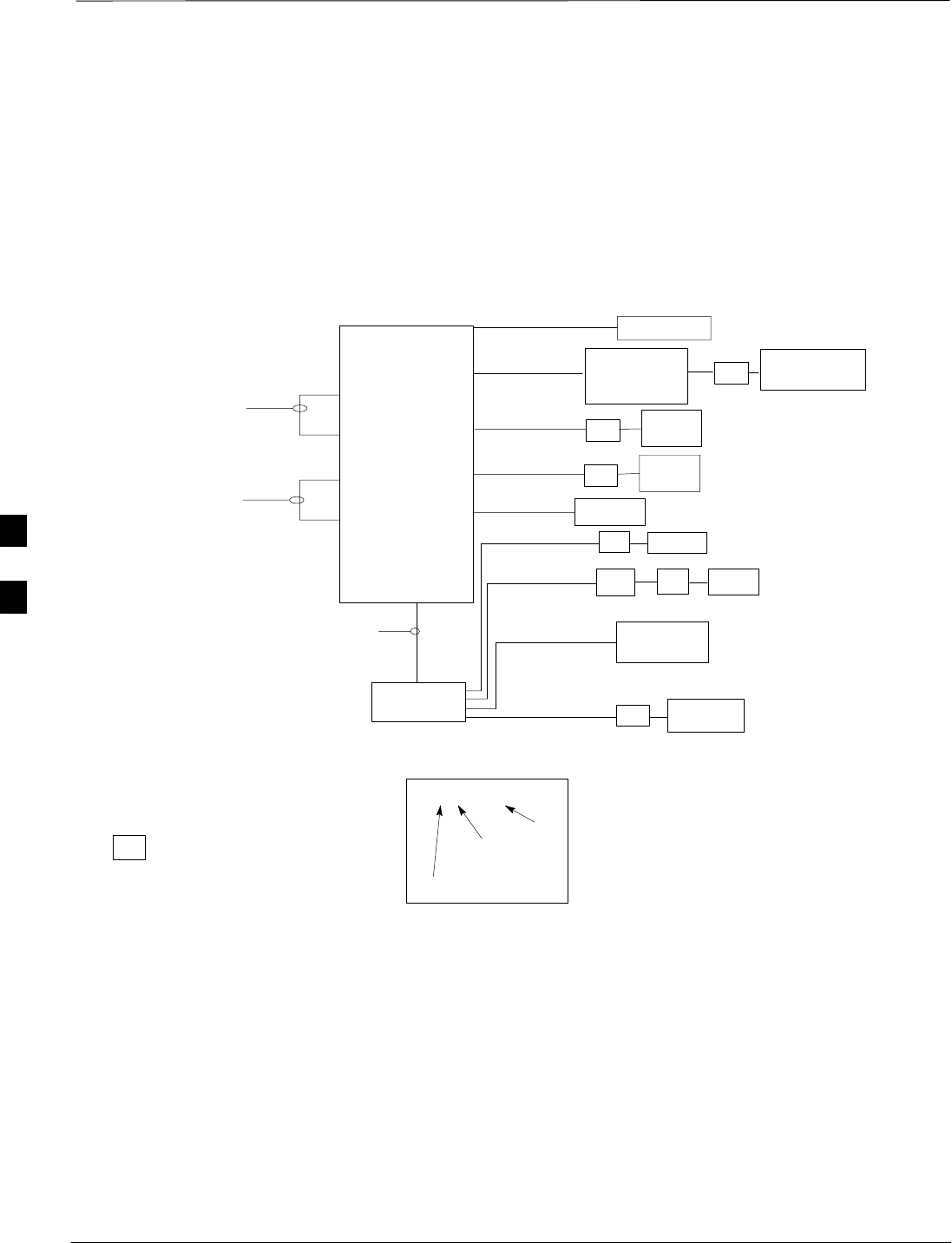
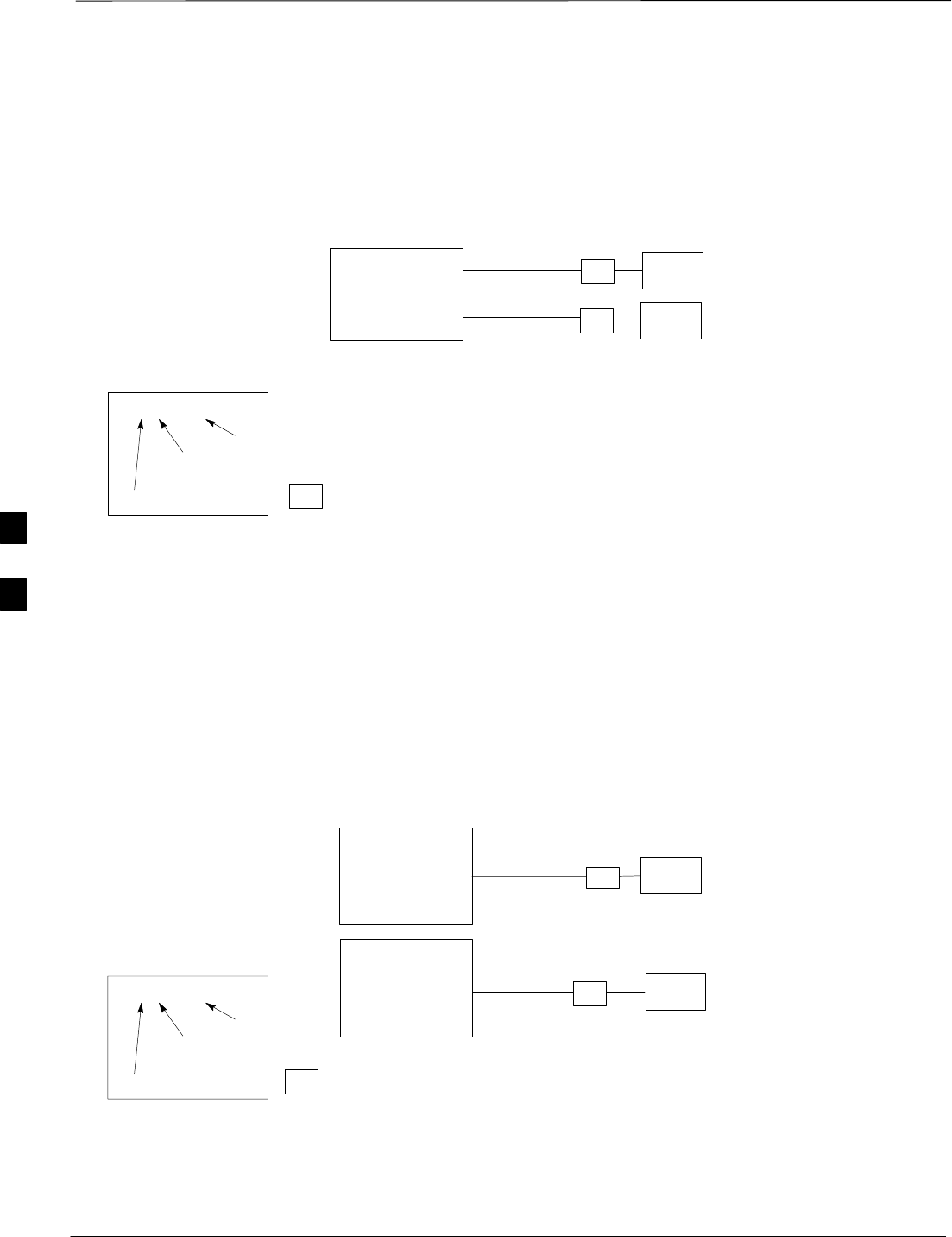
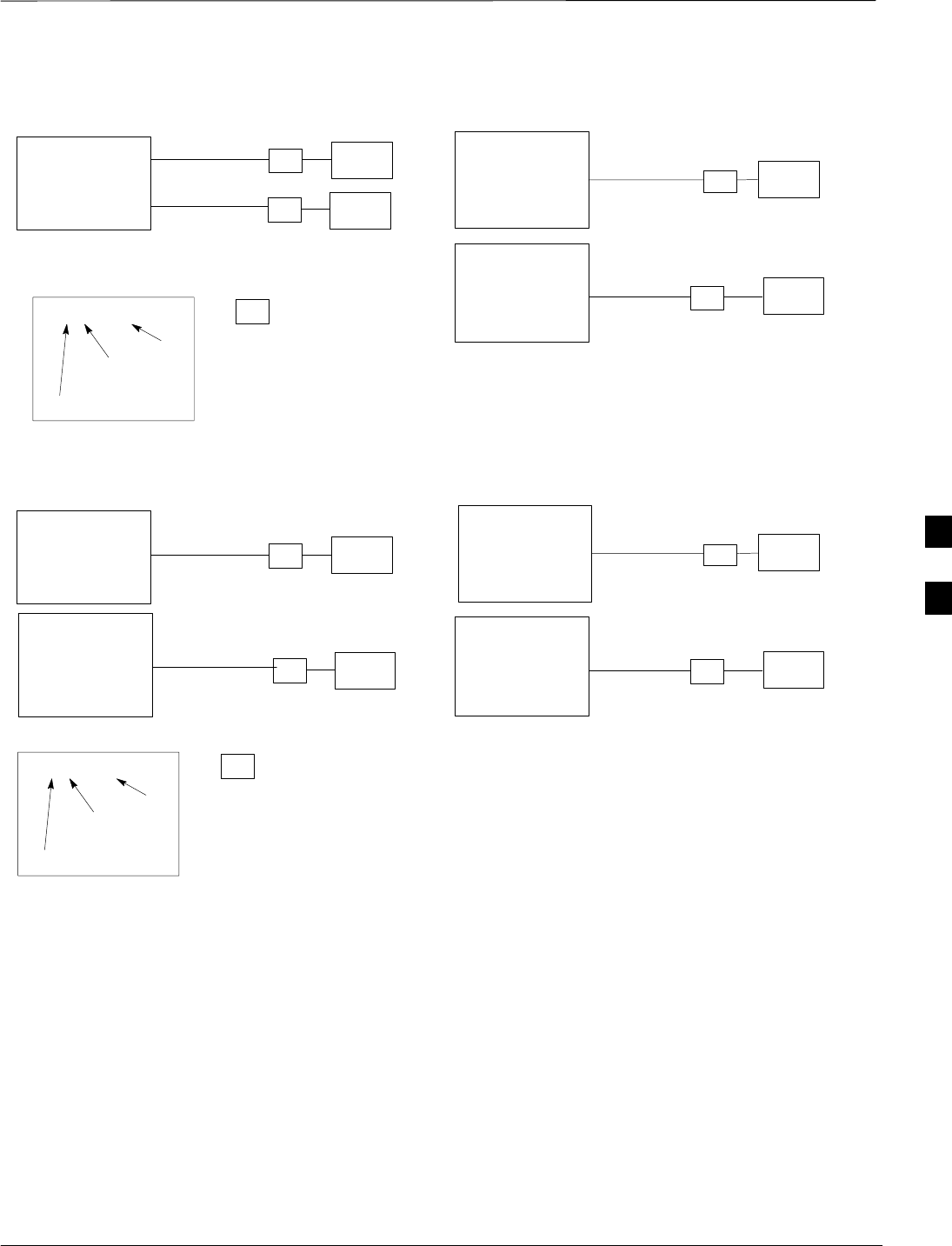
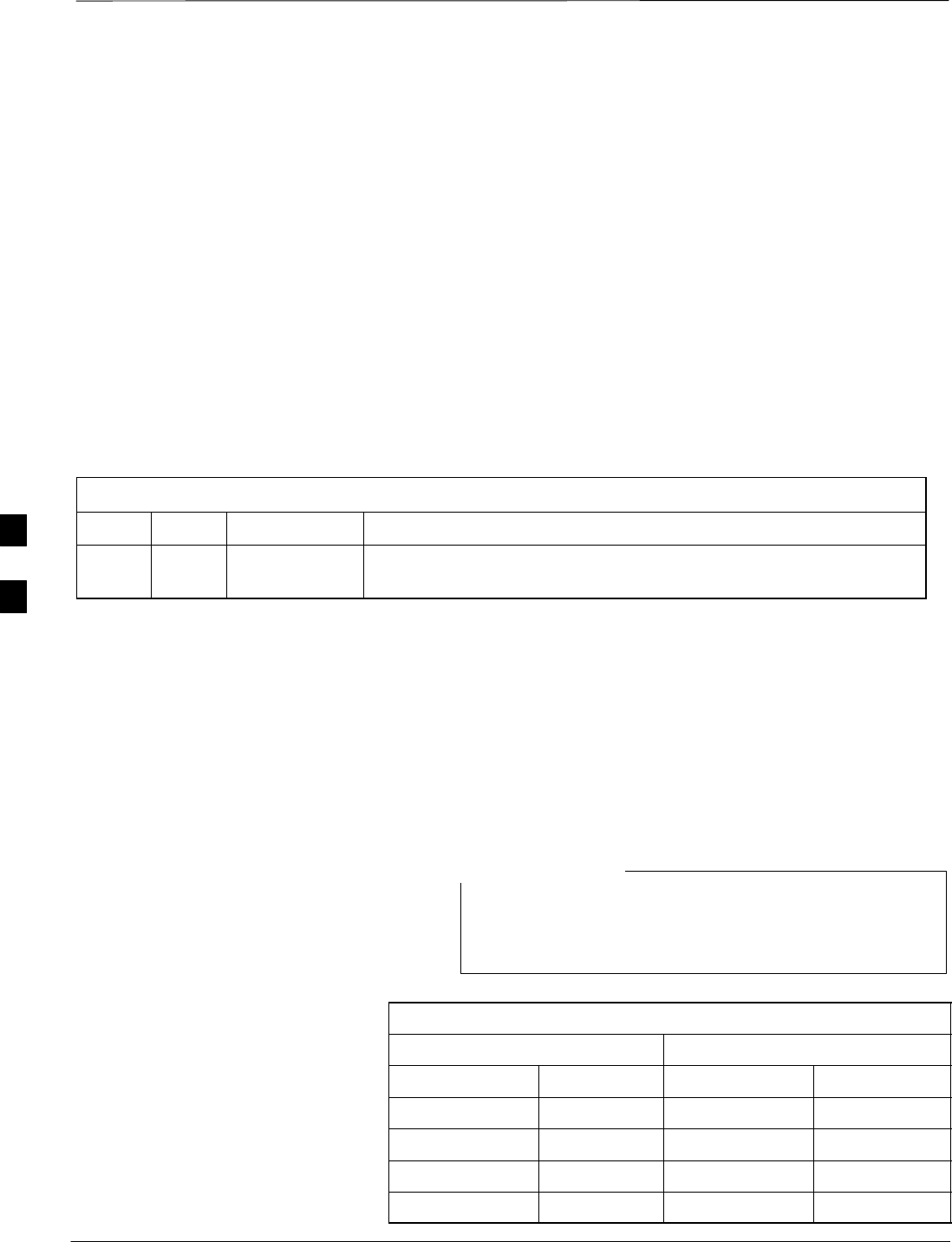
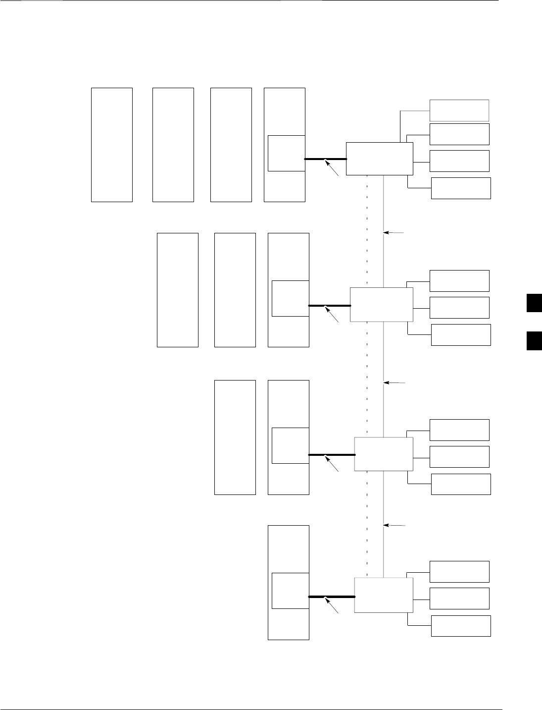
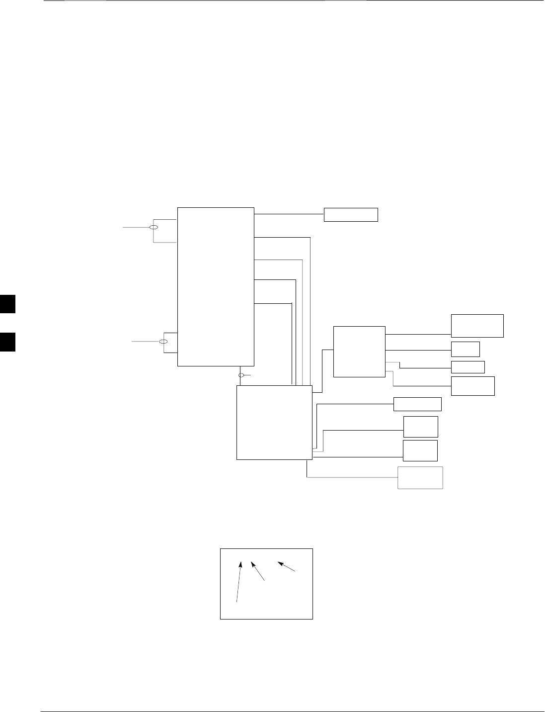
Figure 4-1 through Figure 4-4 shows the scope of work to be performed
for preparing the site cabling with the customer–supplied Site I/O
Interface. Chapter 6 shows the scope of work for unit cabling.
Figure 4-1: Site Cabling for One MicroCell
MICROCELL 1
CUSTOMER
INPUTS
SPAN
RGPS
SITE I/O
INTERFACE PHONE
(MODEM)
LA
LA
DSU
LA
AC POWER
LA
ANT B
TX/RX
LA
DC POWER
GROUND
KEY
B/1(ANTENNA)
LABEL
NUMBER
OF CABLES
NAME
Y/1(GROUND)
C/1(ANTENNA)
S/1(AC POWER)
U/1(DC POWER)
LEGEND
LA = Lightning Arrestor
Z/1 (SITE I/O CABLE)
SEE NOTE 1
P/1 (SU)
M/1 (RGPS)
N/1 (SPAN)
O/1 (CUSTOMER
INPUT)
V/1 (PHONE)
LA
C/1(ANTENNA) ANT A
RX
NOTES:
1. If BTS is not equipped with the primary surge
suppressor, then you will require the Site I/O Cable
Extender Cable, p/n 3088116C01 (cable Z).
2. The AC Installation Box is required for outdoor
applications.
B/1 (GROUND)
AC INSTALL
BOX
(SEE NOTE 2)
4
Site Cabling for BTS With Customer–Supplied Site I/O Interface – continued
JAN 2002 4-7
SCt300 1X BTS Hardware Installation, ATP, and FRU Procedures
DRAFT
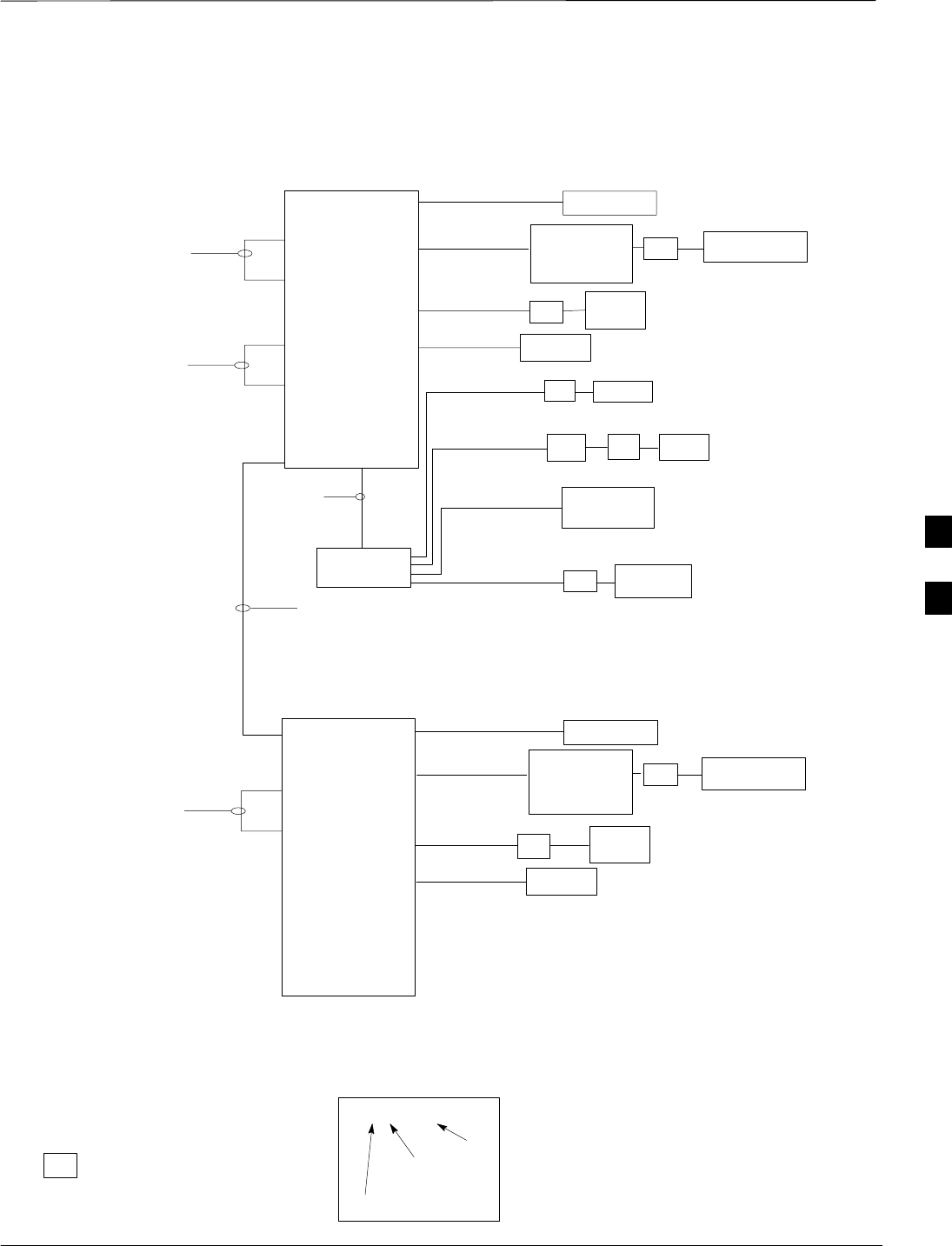
Figure 4-2: Site Cabling for Two MicroCells
MICROCELL 1
CUSTOMER
INPUTS
SPAN
RGPS
SITE I/O
INTERFACE PHONE
(MODEM)
LA
LA
DSU
LA
MICROCELL 2 ANT 2
TX/RX
LA
DC POWER
GROUND
ANT 1
TX/RX
LA
DC POWER
GROUND
KEY
B/1(ANTENNA)
LABEL
NUMBER
OF CABLES
NAME
Y/1(GROUND)
Y/1(GROUND)
D/1(ANTENNA)
D/1(ANTENNA)
U/1(DC POWER)
U/1(DC POWER)
LEGEND
LA = Lightning Arrestor
NOTES
1: Site I/O junction box and associated cable are
present on MicroCell 1 only.
2. If BTS is not equipped with the primary surge
suppressor, then you will require the Site I/O Cable
Extender Cable, p/n 3088116C01 (cable Z).
3. The AC Installation Box is required for outdoor
applications.
E/1 (MIB) OR
K/1 (MIB)
P/1 (SU)
M/1 (RGPS)
N/1 (SPAN)
O/1 (CUSTOMER
INPUT)
V/1 (PHONE)
Z/1 (SITE I/O
CABLE) SEE
NOTES 1
AND 2
B/1 (GROUND)
AC POWER
LA
S/1(AC POWER) AC INSTALL
BOX
(SEE NOTE 3)
AC POWER
LA
S/1(AC POWER) AC INSTALL
BOX
(SEE NOTE 3)
P/1 (SU)
4
Site Cabling for BTS With Customer–Supplied Site I/O Interface – continued
DRAFT
SCt300 1X BTS Hardware Installation, ATP, and FRU Procedures JAN 2002
4-8
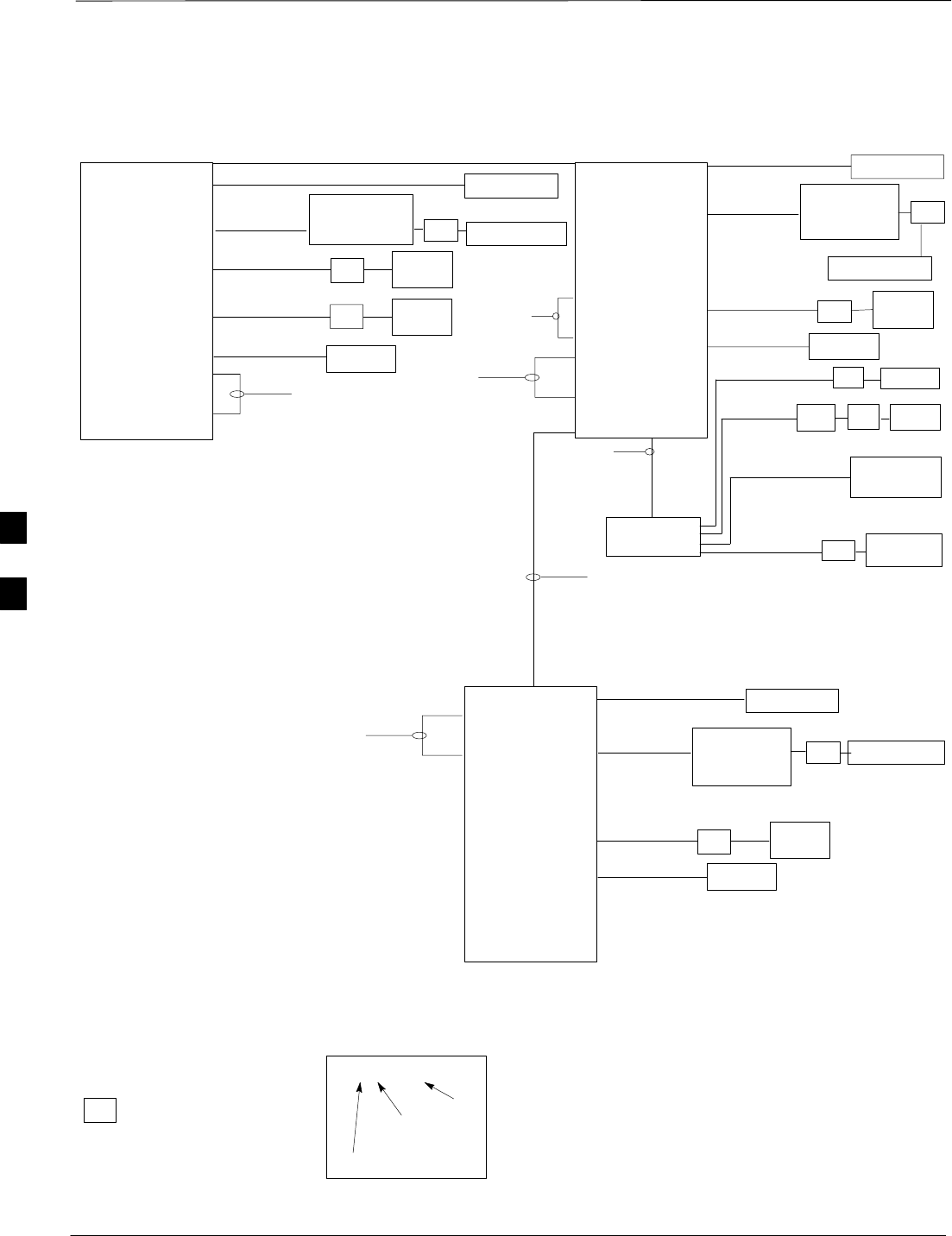
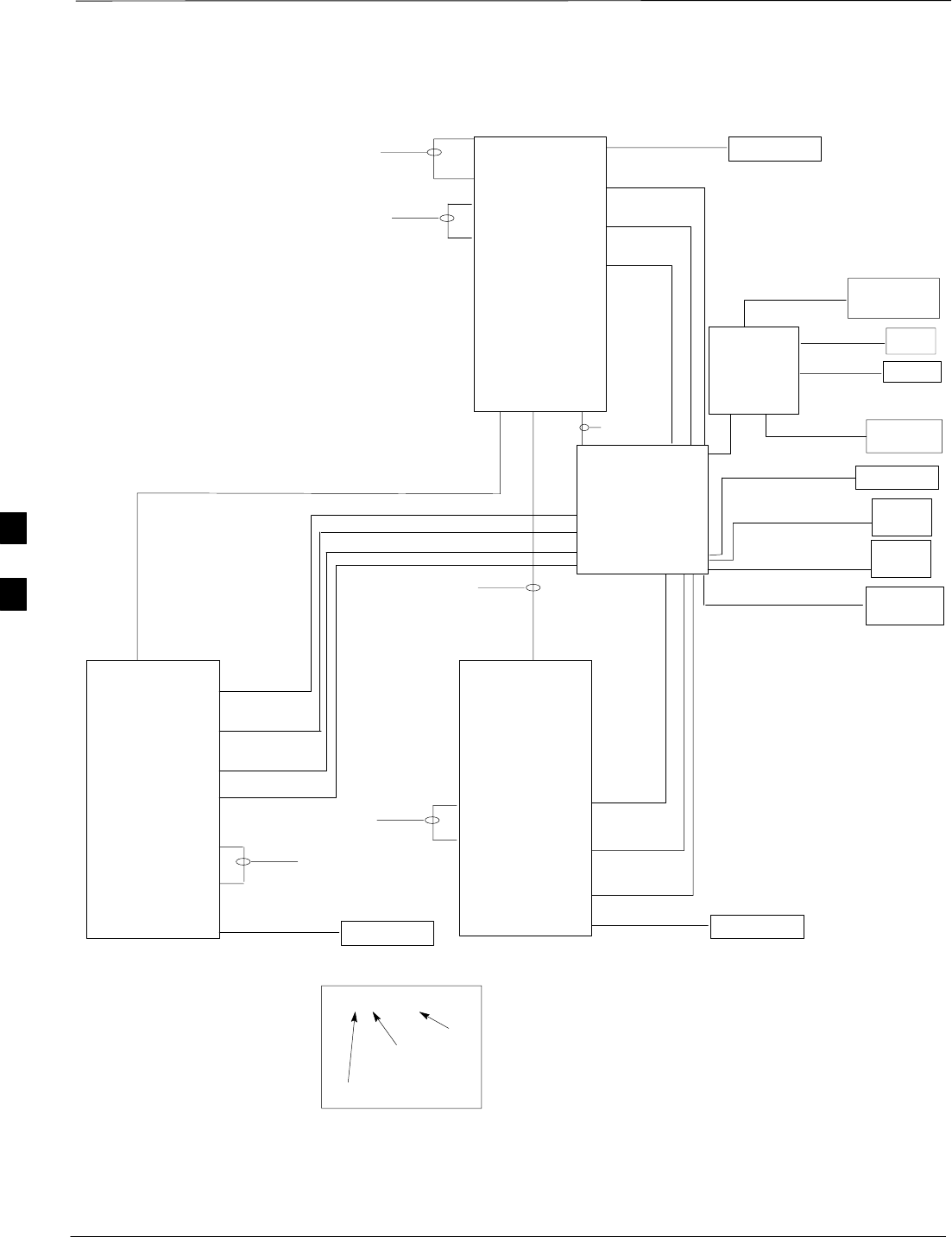
Figure 4-3: Site Cabling for Three MicroCells
MICROCELL 3 MICROCELL 1
CUSTOMER
INPUTS
SPAN
RGPS
SITE I/O
INTERFACE PHONE
(MODEM)
LA
LA
DSU
LA
MICROCELL 2
ANT 4
TX/RX
LA
GROUND
DC POWER
ANT 2
TX/RX
LA
DC POWER
GROUND
ANT 1
TX/RX
LA
DC POWER
GROUND
KEY
B/1(ANTENNA)
LABEL
NUMBER
OF CABLES
NAME
Y/1(GROUND)
Y/1(GROUND)
Y/1(GROUND)
D/1(ANTENNA)
D/1(ANTENNA)
D/1(ANTENNA)
U/1(DC POWER)
U/1(DC POWER)
U/1(DC POWER)
LEGEND
LA = Lightning Arrestor
F/1 (MIB) OR
I/1 (MIB)
E/1 (MIB) OR
K/1 (MIB) OR
LA
D/1(ANTENNA) ANT 3
RX
M/1 (RGPS)
N/1 (SPAN)
O/1 (CUSTOMER
INPUTS)
V/1 (PHONE)
Z/1 (SITE I/O
CABLE) SEE
NOTES 1 AND 2
B/1
(GROUND)
NOTES
1: Site I/O junction box and associated cable are
present on MicroCell 1 only.
2. If BTS is not equipped with the primary surge
suppressor, then you will require the Site I/O Cable
Extender Cable, p/n 3088116C01 (cable Z).
3. The AC Installation Box is required for outdoor
applications.
AC POWER
LA
S/1
(AC POWER) AC INSTALL
BOX
(SEE NOTE 3)
AC POWER
LA
S/1
(AC POWER) AC INSTALL
BOX
(SEE NOTE 3)
AC POWER
LA
S/1
(AC POWER) AC INSTALL
BOX
(SEE NOTE 3)
P/1 (SU)
P/1 (SU)
P/1 (SU)
4
Site Cabling for BTS With Customer–Supplied Site I/O Interface – continued
JAN 2002 4-9
SCt300 1X BTS Hardware Installation, ATP, and FRU Procedures
DRAFT
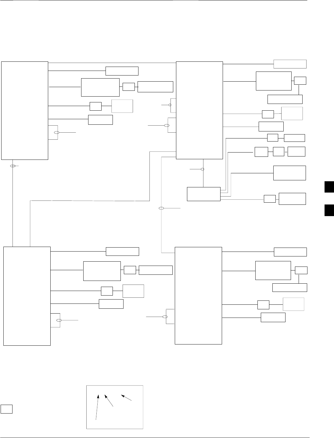
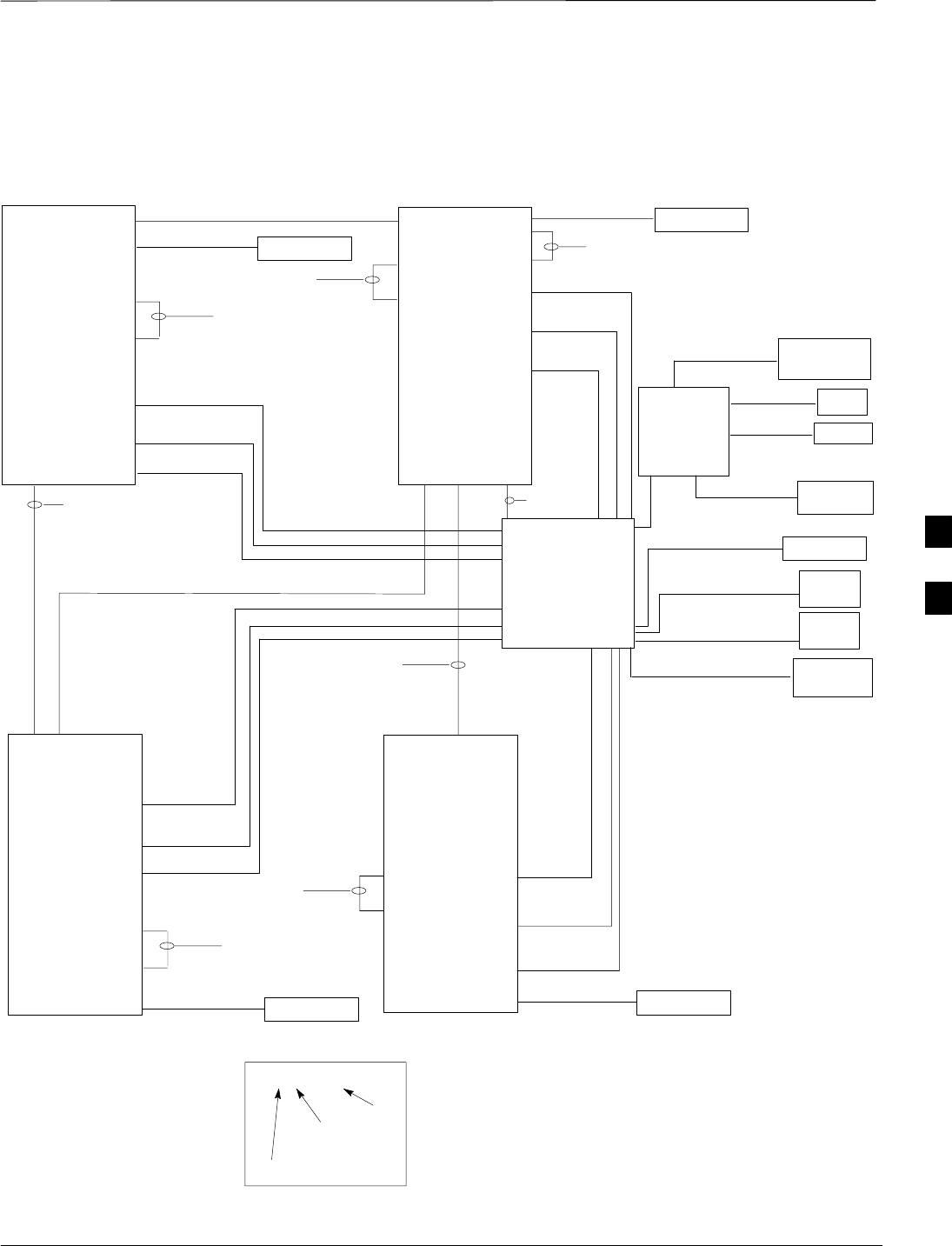
Figure 4-4: Site Cabling for Four MicroCells
MICROCELL 4 MICROCELL 1
MICROCELL 3
CUSTOMER
INPUTS
SPAN
RGPS
SITE I/O
INTERFACE PHONE
(MODEM)
LA
LA
DSU
LA
MICROCELL 2
ANT 4
TX/RX
LA
GROUND
DC POWER
ANT 3
TX/RX
LA
DC POWER
GROUND ANT 2
TX/RX
LA
DC POWER
GROUND
ANT 1
TX/RX
LA
DC POWER
GROUND
KEY
B/1(ANTENNA)
LABEL
NUMBER
OF CABLES
NAME
Y/1(GROUND)
Y/1(GROUND)
Y/1(GROUND)
Y/1(GROUND)
D/1(ANTENNA)
D/1(ANTENNA)
D/1(ANTENNA)
D/1(ANTENNA)
U/1(DC POWER)
U/1(DC POWER)
U/1(DC POWER)
U/1(DC POWER)
LEGEND
LA = Lightning Arrestor
G/1 (MIB) OR
J/1 (MIB)
M/1 (RGPS)
W/1 (SPAN)
O/1 (CUSTOMER
INPUTS)
V/1 (PHONE)
Z/1 (SITE I/O
CABLE) SEE
NOTE
B/1
(GROUND)
NOTES
1: Site I/O junction box and associated cable are
present on MicroCell 1 only.
2. If BTS is not equipped with the primary surge
suppressor, then you will require the Site I/O Cable
Extender Cable, p/n 3088116C01 (cable Z).
3. The AC Installation Box is required for outdoor
applications.
AC POWER
LA
S/1
(AC POWER) AC INSTALL
BOX
(SEE NOTE 3)
AC POWER
LA
S/1
(AC POWER) AC INSTALL
BOX
(SEE NOTE 3)
AC POWER
LA
S/1
(AC POWER) AC INSTALL
BOX
(SEE NOTE 3)
AC POWER
LA
S/1
(AC POWER) AC INSTALL
BOX
(SEE NOTE 3)
F/1 (MIB) OR
I/1 (MIB)
E/1 (MIB) OR
K/1 (MIB) OR
E/1 (MIB) OR
K/1 (MIB) OR
P/1 (SU)
P/1 (SU)
P/1 (SU)
P/1 (SU)
4

Power, Ground, and Battery Cabling for Sites Equipped with
Customer–Supplied Site I/O Interface
DRAFT
SCt300 1X BTS Hardware Installation, ATP, and FRU Procedures JAN 2002
4-10
Objective
The objective of this procedure is to install the power, earth ground, and
battery cabling for one or more Microcell units at a site equipped with
customer–supplied Site I/O Interface.
Dangerous voltages, capable of causing death, are present
in this equipment. Use extreme caution when handling and
testing this equipment.
WARNING
If you are installing the unit outdoors and are not using the
Primary Surge Suppressor, then you must connect AC
power with the AC Installation Box. The AC Installation
Box is included with the non–surge option.
NOTE
Other Grounding
Considerations
This procedure covers only the grounding information for the cables that
attach to one or more MicroCell units. Grounding considerations beyond
the ground cables that attach to the MicroCell are summarized in
Appendix A. Refer to Appendix A and the site documentation for other
grounding considerations.
Motorola recommends that you use an oxide inhibitor such
as Burndy PENETROXt or Ilsco DE–OXt on all the
external ground connections on the unit and on the site I/O
interface for all outdoor installations. This includes the
ground connections on the mounting bracket, the Site I/O,
and the lugs on the customer–supplied site I/O interface.
NOTE
Power Requirements and
Configurations
The power requirements for each unit is: 120–240 VAC (7.5 amps min.)
or 20–30 VDC (20 amps min.) power input.
The AC Installation Box is required for all outdoor installations which
use the customer–supplied Site I/O interface.
The customer–supplied site I/O interface must be able to pass the
4kV/6kV transient impulse test (Motorola 12M09154A49 Sec. 3.5.3.2.1:
Impulse Surge, Test Condition A).
4
Power, Ground, and Battery Cabling for Sites Equipped with
Customer–Supplied Site I/O Interface – continued
JAN 2002 4-11
SCt300 1X BTS Hardware Installation, ATP, and FRU Procedures
DRAFT
The power and battery configurations for the MicroCell units are:
SAC power only (no battery)
SAC power with short duration battery
SDC power
Neither the ”+” or ”–” terminal of the DC Input is
connected to the BTS ground. If a negative supply input is
provided, the ”+” terminal of the DC input must be
connected to the Master Ground Plate (MGP). By
connecting the ”+” terminal of the DC input to the MGP, a
negative supply system is created.
NOTE
Required Cables
Table 4-12 provides the quantity and description of the required cables.
Table 4-12: Required Cables for Power, Earth Ground, and Battery Connections
Cable Qty. Part Number Description
S 1–4 3087854C02 AC input cable, 14 AWG, 5 m, is designed for 88–260 VAC power
input.
U 1–4 3087854C04 DC input cable, 14 and 22 AWG, 5 m, is designed for 20 to 30 VDC
power input.
Y 1–4 Customer
Supplied Master Ground cable, 6 -AWG, insulated copper wire. Requires one
ring lug connector. Used for both Primary Surge Suppressor and
non–Primary Surge Suppressor installations.
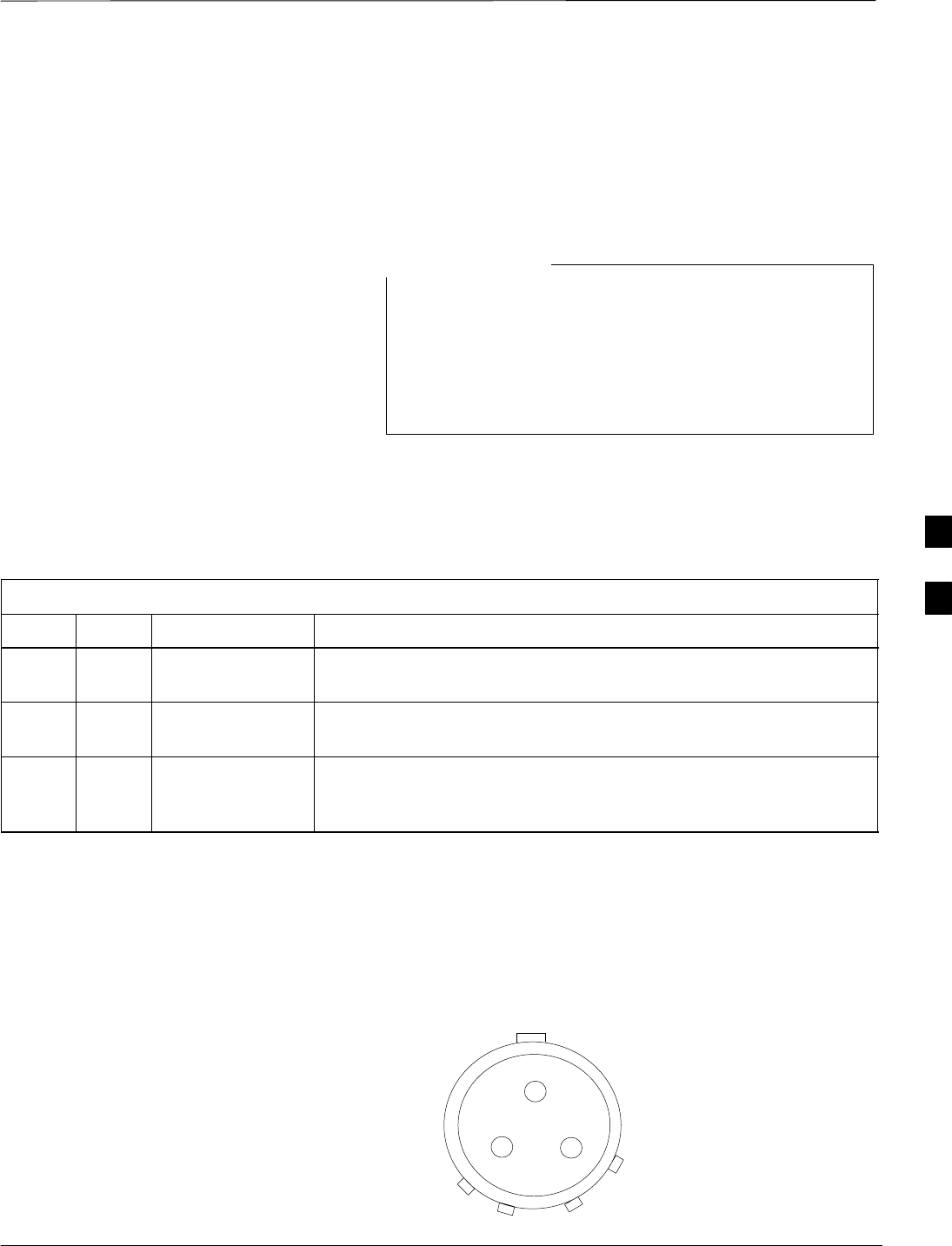
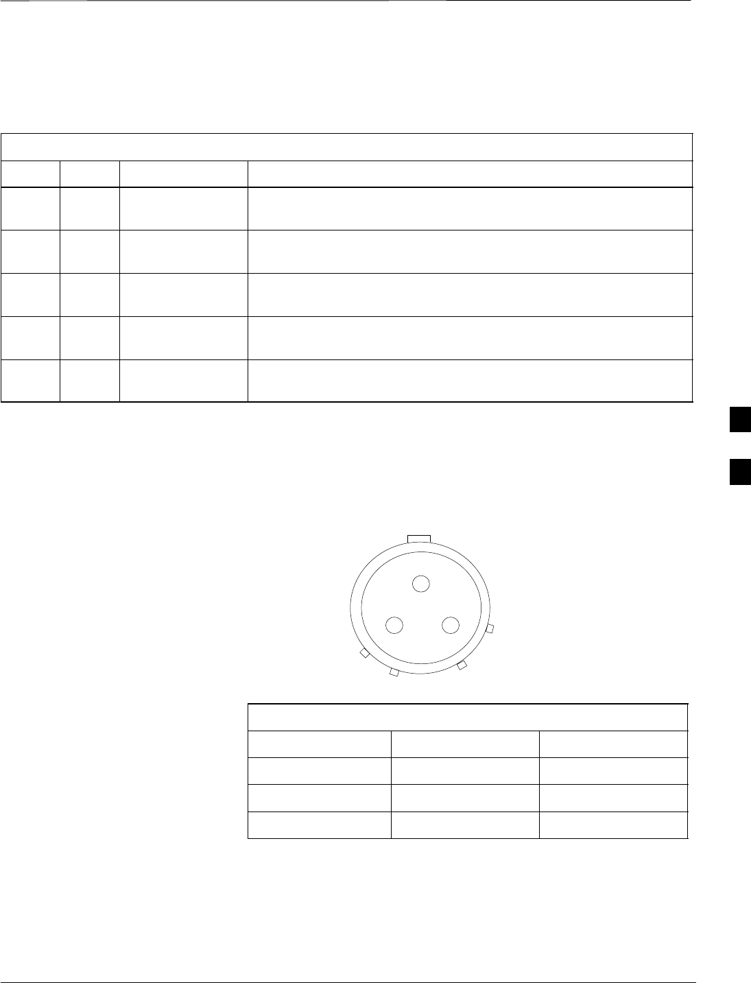
AC Input Cable Information
The pinout information for the AC input cable(s) (Cable S) is given in
Figure 4-5 and Table 4-13.
Figure 4-5: AC Input Cable Connector Information
A
BCSOCKET POSITION ON CABLE
CONNECTOR SHOWN
4
Power, Ground, and Battery Cabling for Sites Equipped with
Customer–Supplied Site I/O Interface – continued
DRAFT
SCt300 1X BTS Hardware Installation, ATP, and FRU Procedures JAN 2002
4-12
Table 4-13: AC Input Cable Information
Connector Wire Color Description
A Black Line
B Green Ground
C White Neutral
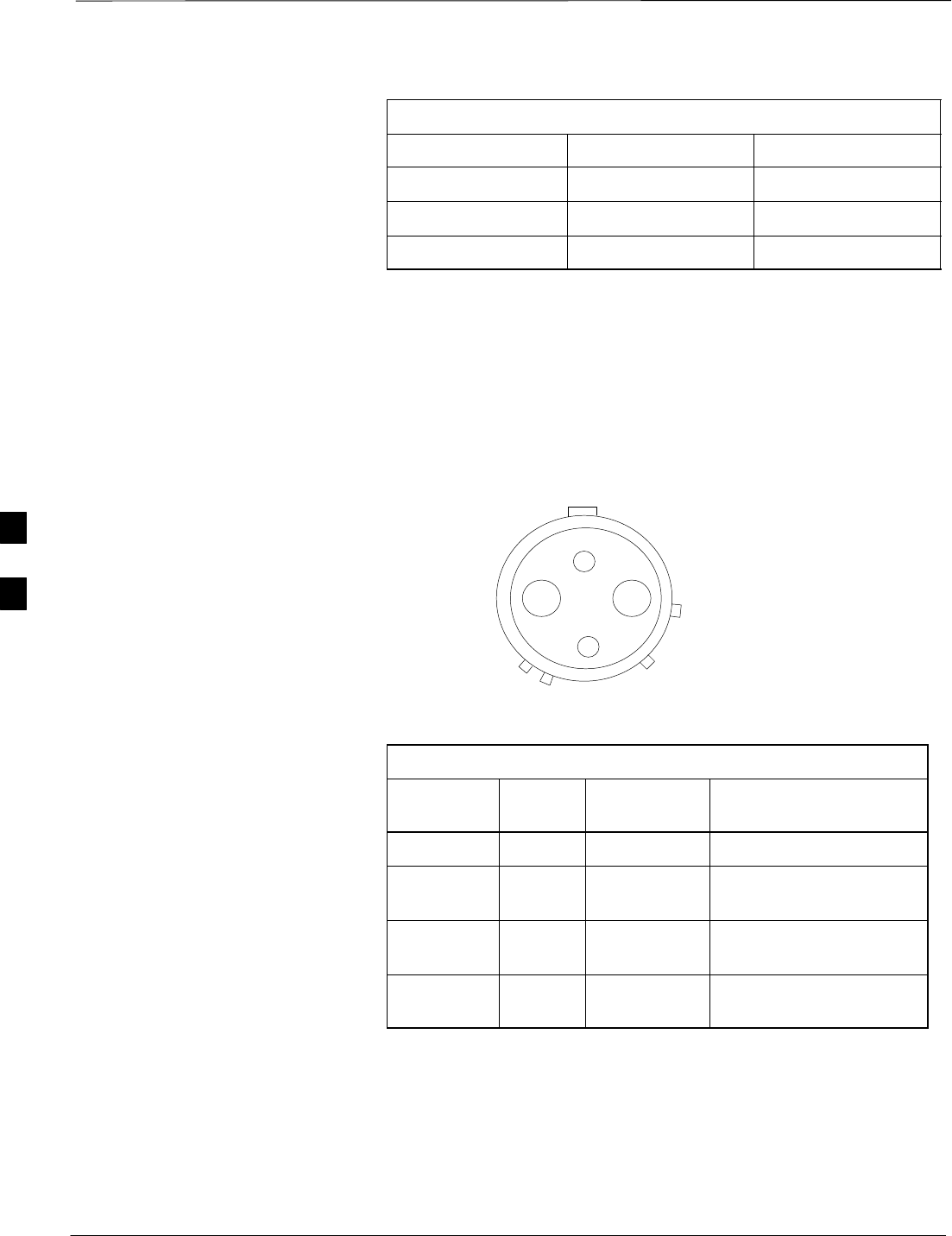
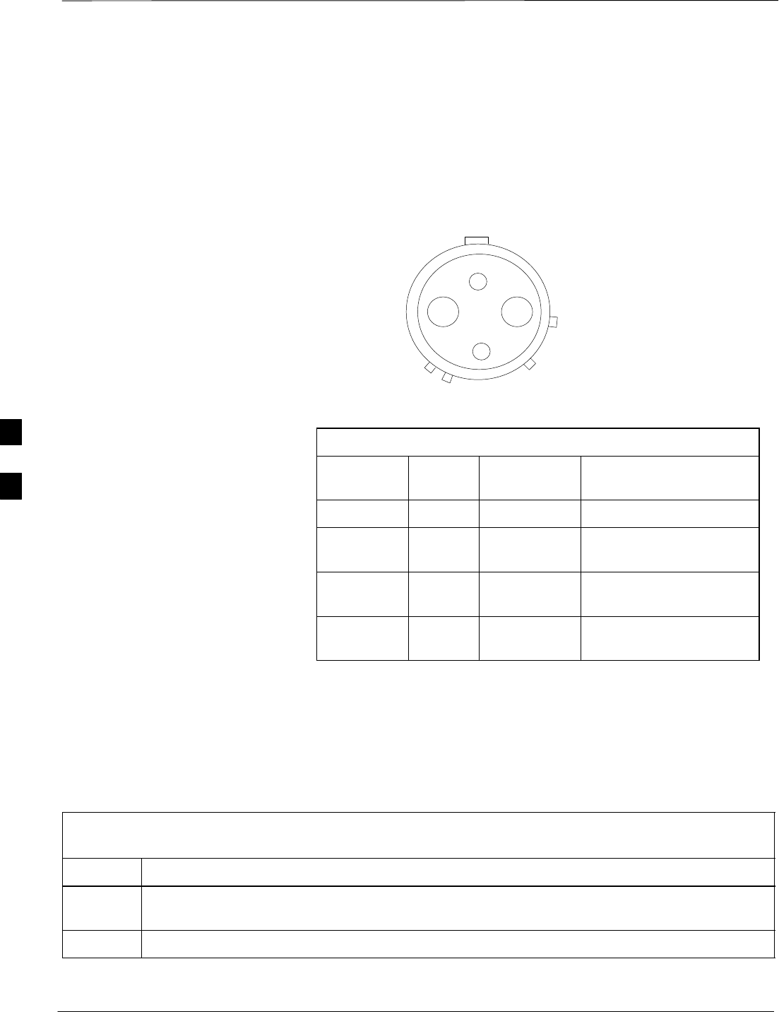
DC Input Cable Information
The information for the DC input cable(s) (Cable U) is given in
Figure 4-6.
Figure 4-6: DC Input Cable Connector Information
A
B
C
DSOCKET POSITION ON
CABLE CONNECTOR SHOWN
Table 4-14: DC Input Cable Information
Connector Wire
Color Description Comments
A Yellow Switch A No connection
B Red Positive Connect to positive
terminal of supply.
C Blue Switch B Connect to negative
terminal of supply.
D Black Negative Connect to negative
terminal of supply.
Procedures to Install Earth
Ground, AC/DC Power, and
Battery Cabling
The system configuration determines which power cables are installed.
The ground cable is always installed. Perform the appropriate
procedures from the following tables based on the system configuration.
4

Power, Ground, and Battery Cabling for Sites Equipped with
Customer–Supplied Site I/O Interface – continued
JAN 2002 4-13
SCt300 1X BTS Hardware Installation, ATP, and FRU Procedures
DRAFT
Table 4-15: Procedure to Install Earth Ground Cable
Step Action
1Route cable Y (ground cable) from the ground on the mounting bracket to the customer defined
grounding location.
2Connect cable Y to the customer defined master ground plate.
Table 4-16: Procedure to Install AC Input Cable(s) (Indoor Applications)
Step Action
1If you will not use the AC Installation box, cut off the male connector (with pins) from the AC
input power cable (cable S).
2Connect the loose wires of cable S (AC input cable) to the customer defined AC power source.
Refer to Table 4-13 for wiring information.
3Verify all connections of cable S with an ohmmeter prior to routing the cable.
4Route cable S from the AC power supply to the unit location.
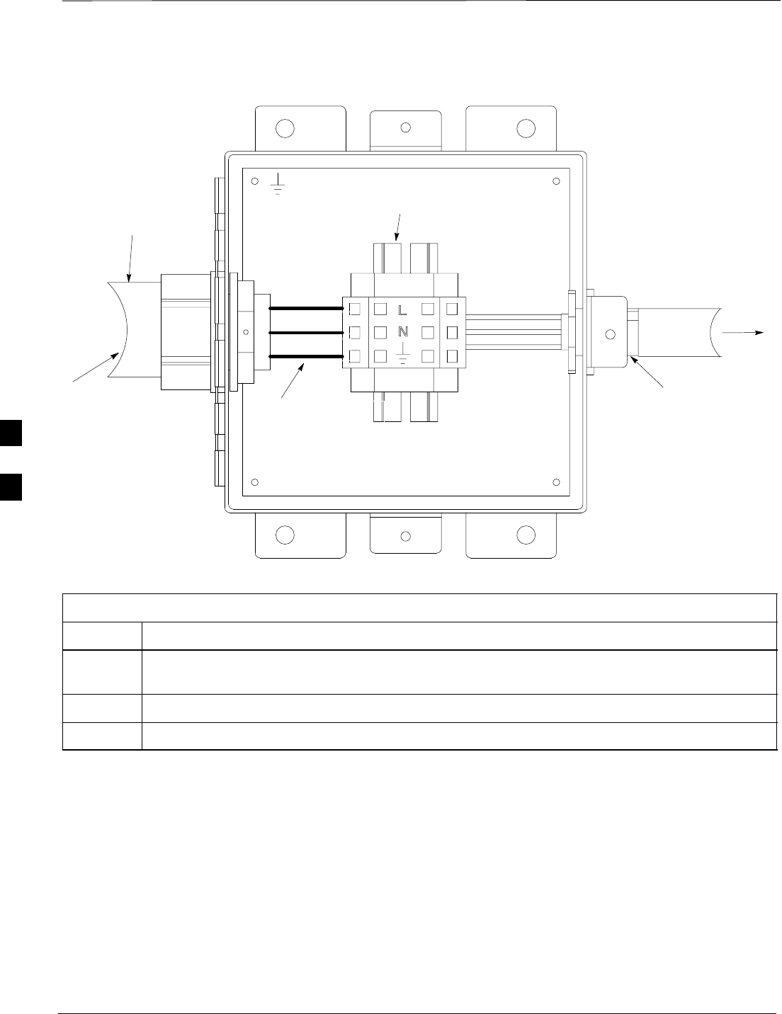
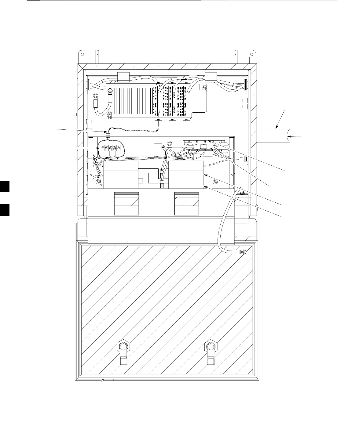
Table 4-17: Procedure to Install AC Installation Box (Optional – Required for Outdoor Installations)
Step Action
1Route the AC Power Cable (cable T) through 1–in. conduit from the customer–defined AC power
source to the AC Installation box. Refer to Figure 4-7 and Table 4-18.
2Attach the wires of cable T to the AC Installation Box terminal block. Refer to Figure 4-7 and
Table 4-18.
3Place the round, black connector on the AC input cable (cable S) onto the AC power cable
connector on the AC installation box. Turn the cable connector to align its key.
4Route cable S from the AC installation box to the unit location.
Table 4-18: AC Installation Box Cabling
Punchdown Block
Connector AC Power Cable
Wire Color Description
L Black Line
N White Neutral
GROUND Green Ground
4
Power, Ground, and Battery Cabling for Sites Equipped with
Customer–Supplied Site I/O Interface – continued
DRAFT
SCt300 1X BTS Hardware Installation, ATP, and FRU Procedures JAN 2002
4-14
Figure 4-7: AC Installation Box
AC POWER CABLE
CONNECTOR
NOTE: Shown with door removed for clarity
1–IN AC
CONDUIT
TO MICROCELL
LOCATION
CUSTOMER
AC INPUT
TERMINAL
BLOCK
LINE
NEUTRAL
GROUND
CUSTOMER POWER
CONNECTIONS
Table 4-19: Procedure to Install DC Input Cable(s)
Step Action
1Connect the loose wires of cable U (DC input cable) to the customer defined DC power source.
Refer to Table 4-14 for wiring information.
2Verify all connections of cable U with an multimeter prior to routing the cable.
3Route cable U from the DC power supply to the unit location.
4
Antenna Cabling for Sites Equipped with Customer–Supplied Site I/O
Interface
JAN 2002 4-15
SCt300 1X BTS Hardware Installation, ATP, and FRU Procedures
DRAFT
Objective
The objective of this procedure is to install the cabling for the
antenna(s). This cabling is installed between one or more units and the
customer–supplied lightning arrestor(s).
Cable Labels
The cable designations are referenced to Table 4-1 in the “Cable
Description” area of this chapter.
Required Cables
Table 4-20 provides the quantities and descriptions of the required
cables.
Table 4-20: Required Cables for Antenna Connections
Cable Qty. Part Number Description
C1 to 8 Customer Supplied Antenna cable, 50–Ohm coaxial terminated with at least one male,
N–type connector.
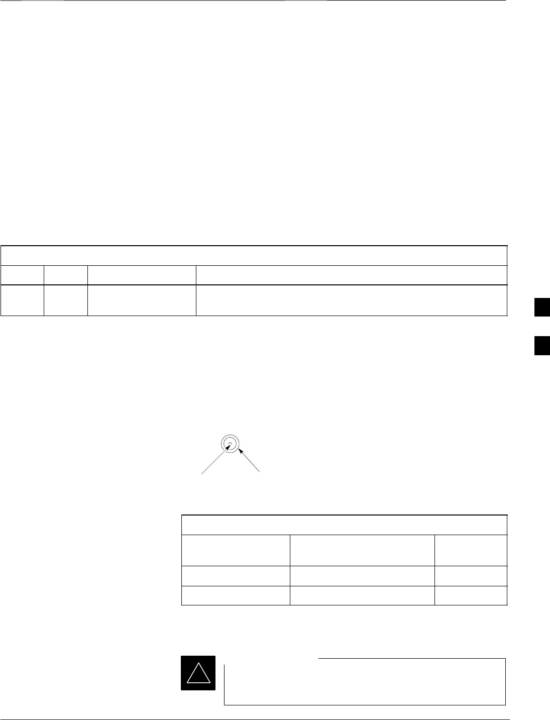
Antenna Cable Pin and Signal
Information
The antenna cabling uses a 50–Ohm coaxial cable. The inner conductor
provides signaling and the outer conductor provides shielding and
ground. Refer to Figure 4-8 and Table 4-21.
Figure 4-8: Antenna Cabling Details
OUTER
CONDUCTOR
INNER
CONDUCTOR
ANTENNA CABLE (COAXIAL)
CONNECTOR
Table 4-21: Pin and Signal Information for Cable C (Antenna Cable)
Antenna Inner Conductor Outer
Conductor
B TX/RX Ground
A RX Ground
Procedure to Install Antenna
Cabling for One Microcell
You must install lightning arrestors for all outdoor
installations.
IMPORTANT
*
4
Antenna Cabling for Sites Equipped with Customer–Supplied Site I/O
Interface – continued
DRAFT
SCt300 1X BTS Hardware Installation, ATP, and FRU Procedures JAN 2002
4-16
Route the antenna cable between the unit and the customer–supplied
lightning arrestor. Refer to Figure 4-9 and Table 4-21. If a lighting
arrestor is not required, route the cabling directly to the antenna.
Figure 4-9: Antenna Cabling for One MicroCell
MICROCELL 1
ANT 4
TX/RX
LA
ANT 3
RX
LA
KEY
B/1(ANTENNA)
LABEL
NUMBER
OF CABLES
NAME
C/1(ANTENNA)
C/1(ANTENNA)
LA =LIGHTNING
ARRESTOR
Procedure to Install Antenna
Cabling for Multi–Unit Logical
BTS Sites
If your site has more than one MicroCell unit, refer to Figure 4-10
through Figure 4-12 for site cabling information. Route the antenna
cables between the units and the customer–supplied lightning arrestors.
If lighting arrestors are not required, route the cabling directly to the
antennas.
Figure 4-10: Antenna Cabling for Two MicroCells
MICROCELL 1
MICROCELL 2 ANT 2
TX/RX
LA
ANT 1
TX/RX
LA
KEY
B/1(ANTENNA)
LABEL
NUMBER
OF CABLES
NAME
C/1(ANTENNA)
C/1(ANTENNA)
LA =LIGHTNING
ARRESTOR
4
Antenna Cabling for Sites Equipped with Customer–Supplied Site I/O
Interface – continued
JAN 2002 4-17
SCt300 1X BTS Hardware Installation, ATP, and FRU Procedures
DRAFT
Figure 4-11: Antenna Cabling for Three MicroCells
MICROCELL 3 MICROCELL 1
MICROCELL 2
ANT 4
TX/RX
LA
ANT 3
RX
LA
ANT 2
TX/RX
LA
ANT 1
TX/RX
LA
KEY
B/1(ANTENNA)
LABEL
NUMBER
OF CABLES
NAME
C/1(ANTENNA)
C/1(ANTENNA)
C/1(ANTENNA)
C/1(ANTENNA)
LA =LIGHTNING
ARRESTOR
Figure 4-12: Antenna Cabling for Maximum of Four MicroCells
MICROCELL 4 MICROCELL 1
MICROCELL 3 MICROCELL 2
ANT 4
TX/RX
LA
ANT 3
TX/RX
LA ANT 2
TX/RX
LA
ANT 1
TX/RX
LA
KEY
B/1(ANTENNA)
LABEL
NUMBER
OF CABLES
NAME
C/1(ANTENNA) C/1(ANTENNA)
C/1(ANTENNA)
C/1(ANTENNA)
LA =LIGHTNING
ARRESTOR
4

Site I/O , Span Line, RGPS and Modem Cabling for Sites Equipped with
Customer–Supplied Site I/O Interface
DRAFT
SCt300 1X BTS Hardware Installation, ATP, and FRU Procedures JAN 2002
4-18
Objective
The objective of this procedure is to install the Site I/O cable between
the Site I/O junction box and the customer–supplied Site I/O interface.
This procedure also covers the installation of the site cabling of the span
line, RGPS and modem cabling to the site I/O interface.
If your multi–unit BTS is equipped with the optional Primary Surge
Suppressor, refer to the “Primary Surge Suppressor Cabling” procedures
in chapter 5.
Cable Labels
The cable designations are referenced to Table 4-1 in the “Cable
Description” area of this chapter.
Required Cables
Table 4-22 provides the quantities and descriptions of the required
cables.
Table 4-22: Required Cables for Site I/O, Span Line, RGPS, and Modem Cabling
Cable Qty. Part Number Description
M 1 3086039H11 RGPS cable, 125 ft.
3086039H12 RGPS cable, 250 ft.
3086039H13 RGPS cable, 500 ft.
3086039H14 RGPS cable, 1000 ft.
3086039H15 RGPS cable, 2000 ft.
N 1 Customer Supplied Span Cable. 22–24 AWG solid copper twisted pair.
O 1 Customer Supplied Customer Input Cable. 22–24 AWG solid copper twisted pair.
V 1 Customer Supplied Phone (Modem) Cable. 22–24 AWG solid copper twisted pair.
Z 1 3088116C01 Site I/O Extender Cable. Required for use in a BTS not equipped
with the Primary Surge Suppressor.
Site I/O Cabling
The Site I/O interface and cabling are customer–supplied. The cable
between the Site I/O junction box and the Site I/O interface is part of the
Site I/O junction box and is supplied by Motorola. If your BTS uses the
customer–supplied Site I/O Interface instead of the Primary Surge
Suppressor, then you will need to use the Site I/O Extender Cable (Cable
Z). The Site I/O Extender cable is included with this option.
The customer determines the Site I/O interface configuration. The end
result is the correct signals getting to the correct pins on the Site I/O
cable.
4
Site I/O , Span Line, RGPS and Modem Cabling for Sites Equipped with
Customer–Supplied Site I/O Interface – continued
JAN 2002 4-19
SCt300 1X BTS Hardware Installation, ATP, and FRU Procedures
DRAFT
Procedure to Install Site I/O
Cable Between Site I/O
Junction Box and Site I/O
Interface
Route the Site I/O junction box cable from the unit location(s) to the Site
I/O Extender Cable (cable Z). Route cable Z to the Site I/O interface.
Connect the appropriate connectors within the Site I/O interface. Refer
to Figure 4-13 and Table 4-23.
If lightning arrestors are required, they must be customer–supplied.
Lightning arrestors are not necessary for sites equipped with optional
Primary Surge Suppressor.
Figure 4-13: Site I/O Cabling Details
CUSTOMER
INPUTS
SPAN
RGPS
PHONE(MODEM)
SITE I/O
INTERFACE
SITE I/O
JUNCTION BOX
SITE I/O
CABLE
MN
O
V
Z
DEUTSCHE
CONNECTOR
4

Site I/O , Span Line, RGPS and Modem Cabling for Sites Equipped with
Customer–Supplied Site I/O Interface – continued
DRAFT
SCt300 1X BTS Hardware Installation, ATP, and FRU Procedures JAN 2002
4-20
Pin and Signal Information for
Site I/O Cabling
Table 4-23 gives the pin and signal information for the Site I/O cable.
Table 4-23: Pin/Signal Information for Site I/O Cable
BTS Interface Wire/Stripe
Color Description
Black Customer Input 1 Signal
Brown Customer Input 1 Ground
Red Customer Input 2 Signal
Orange Customer Input 2 Ground
Yellow Customer Input 3 Signal
Green Customer Input 3 Ground
Blue Customer Input 4 Signal
Purple Customer Input 4 Ground
Customer Input Grey Customer Input 5 Signal
White Customer Input 5 Ground
Black/Brown Customer Input 6 Signal
Black/Red Customer Input 6 Ground
Black/Orange Customer Input 7 Signal
Black/Yellow Customer Input 7 Ground
Black/Green Customer Input 8 Signal
Black/Blue Customer Input 8 Ground
Black/Purple Data to Tail –
Black/Grey Data to Tail +
Black/White Data from Tail –
Brown/Black Data from Tail +
Brown/Red 1 PPS to Tail –
Sync Reverse Brown/Orange 1 PPS to Tail +
Brown/Yellow 1 PPS from Tail –
Brown/Green 1 PPS from Tail +
Brown/Blue Downstream BTS Detect +
Brown/Purple Downstream BTS Detect –
. . . continued on next page
4

Site I/O , Span Line, RGPS and Modem Cabling for Sites Equipped with
Customer–Supplied Site I/O Interface – continued
JAN 2002 4-21
SCt300 1X BTS Hardware Installation, ATP, and FRU Procedures
DRAFT
Table 4-23: Pin/Signal Information for Site I/O Cable
BTS Interface DescriptionWire/Stripe
Color
Brown/Grey Data from Head –
Brown/White Data from Head +
Red/Black Data to Head –
Red/Brown Data to Head +
Red/Orange 1 PPS from Head –
Red/Yellow 1 PPS from Head +
Red/Green 1 PPS to Head –
Red/Blue 1 PPS to Head +
Sync Forward Red/Purple RGPS 28V
Red/Grey RGPS Ground
Red/White RGPS 28V
Orange/Black RGPS Ground
Orange/Brown RGPS 28V
Orange/Red RGPS Ground
Orange/Yellow NO CONNECTION
Orange/Green NO CONNECTION
Orange/Blue RX TIP Primary (Network)
Orange/Purple RX RING Primary (Network)
Orange/Grey TX TIP Primary (Network)
Orange/White TX RING Primary (Network)
Span (Network) Yellow/Black RX TIP Secondary (Network)
Yellow/Brown RX RING Secondary (Network)
Yellow/Red TX TIP Secondary (Network)
Yellow/Orange TX RING Secondary (Network)
. . . continued on next page
4

Site I/O , Span Line, RGPS and Modem Cabling for Sites Equipped with
Customer–Supplied Site I/O Interface – continued
DRAFT
SCt300 1X BTS Hardware Installation, ATP, and FRU Procedures JAN 2002
4-22
Table 4-23: Pin/Signal Information for Site I/O Cable
BTS Interface DescriptionWire/Stripe
Color
Yellow/Green RX TIP Primary (Redundant)
Yellow/Blue RX RING Primary (Redundant)
Yellow/Purple TX TIP Primary (Redundant)
Yellow/Grey TX RING Primary (Redundant)
Span (Redundant) Yellow/White RX TIP Secondary (Redundant)
Green/Black RX RING Secondary (Redundant)
Green/Brown TX TIP Secondary (Redundant)
Green/Red TX RING Secondary (Redundant)
Green/Orange MODEM TIP
Green/Yellow MODEM TIP
Green/Blue No connection
Phone (Modem) Green/Purple No connection
Green/Grey MODEM RING
Green/White MODEM RING
Connecting Customer–Defined
Inputs to the Site I/O Interface
The unit provides eight customer–defined inputs for connection to
external contacts. Each input (a signal/ground pair) is monitored for an
“OPEN” (>50 k Ohms) or “CLOSED” (<3 Ohms) condition.
4

Site I/O , Span Line, RGPS and Modem Cabling for Sites Equipped with
Customer–Supplied Site I/O Interface – continued
JAN 2002 4-23
SCt300 1X BTS Hardware Installation, ATP, and FRU Procedures
DRAFT
Connecting the RGPS Cable to
the Site I/O Interface
The RGPS (cable M) is connected to the Site I/O interface (Sync
Forward) of the BTS. Table 4-24 provides the Sync Forward to RGPS
connections.
Table 4-24: Connecting the RGPS to the Site I/O Cable
Site I/O Cable RGPS (Cable M)
Sync Forward
Descriptions Sync Forward Color
Code (wire/stripe) RGPS Description RGPS Color Code
(wire/stripe)
Data from Head –Brown/Grey Transmit Port –Green/Black
Data from Head + Brown/White Transmit Port + Green
Data to Head –Red/Black Receive Port –White/Black
Data to Head + Red/Brown Receive Port + White
1 pps from Head –Red/Orange 1 PPS Timing –Brown/Black
1 pps from Head + Red/Yellow 1 PPS Timing + Brown
RGPS 28 V Red/Purple Power 1 Blue
Red/White
RGPS Ground Red/Grey DC Ground 1 Blue/Black
Orange/Black
RGPS 28 V Orange/Brown Power 2 Yellow
RGPS Ground Orange/Red DC Ground 2 Yellow/Black
No connect N/A No connect Red
No connect N/A No connect Red/Black
NOTE: The Orange/Yellow and Orange/Green wires should be trimmed back to the grey outer jacket of the
Site I/O cable.
Connecting the Span Line
Cable to the Site I/O Interface
The unit provides two, four–wire T1/E1 interfaces for backhaul support.
Each interface is made up of Transmit Tip/Ring and Receive Tip/Ring
connections.
The Transmit and Receive data flow is given from the perspective of the
unit. Only a single span line (Primary) is required for BTS operation.
Connecting a Phone Line to the
Site I/O Interface (Modem
Support)
The unit provides a two–wire analog phone line interface for modem
support. The unit Tip and Ring signals are connected to the external
phone line Tip and Ring.
4

RGPS Cabling for Multiple BTS Sites
DRAFT
SCt300 1X BTS Hardware Installation, ATP, and FRU Procedures JAN 2002
4-24
Objective
This procedure gives information to connect multiple BTS sites for both
RGPS (synchronous) and HSO (non–synchronous) configurations in
both indoor and outdoor applications.
Background
The RGPS only connects to the first unit of a multi–unit logical BTS.
This first unit sends timing signals to all other units. You only need to
connect the site I/O interfaces of each multi–unit logical BTS to each
other. This allows “sharing” of a single RGPS antenna between several
single or multi–unit logical BTSs.
This also applies to systems using HSO instead of RGPS. The HSO
timing is “shared” in the same way.
Required Tools and Equipment
Cables
The RGPS Synchronization Cable is contained in the Motorola kits
listed in Table 4-25:
Table 4-25: Required Cables for RGPS Cabling for Multiple BTS Sites
Cable Qty. Part Number Description
X 1–11 3086039H18 RGPS Synchronization cable (part of kit SGKN4351A).
3086039H19 RGPS Synchronization cable (part of kit SGKN4352A).
Motorola kits
Table 4-26 and Table 4-27 show the contents of Motorola kits
SGKN4351A and SGKN4352A. These kits are necessary for RGPS
cabling between multiple BTS locations.
Table 4-26: RGPS Synchronization Cable Kit – SGKN4351A
Cable Qty. Motorola Part
Number Description
X 1 3086039H18 RGPS Sync Cable, 2000 ft.
n/a 2 5864461A03 Fitting, liquid tight.
n/a 2 0264599A02 Nut, nylon locking
Table 4-27: RGPS Synchronization Cable Kit – SGKN4352A
Cable Qty. Motorola Part
Number Description
X 1 3086039H19 RGPS Sync Cable, 3280 ft.
n/a 2 5864461A03 Fitting, liquid tight.
n/a 2 0264599A02 Nut, nylon locking
4

RGPS Cabling for Multiple BTS Sites – continued
JAN 2002 4-25
SCt300 1X BTS Hardware Installation, ATP, and FRU Procedures
DRAFT
Surge suppressors
Surge suppressors (Polyphaser 097–1017A–A.1) are required for certain
installations.
Cable Diagrams and
Description
Figure 4-18 shows the RGPS cabling for a multi–BTS configuration for
an RGPS (synchronous) configuration. Figure 4-19 shows the RGPS
cabling for a multi–BTS HSO (non–synchronous) configuration.
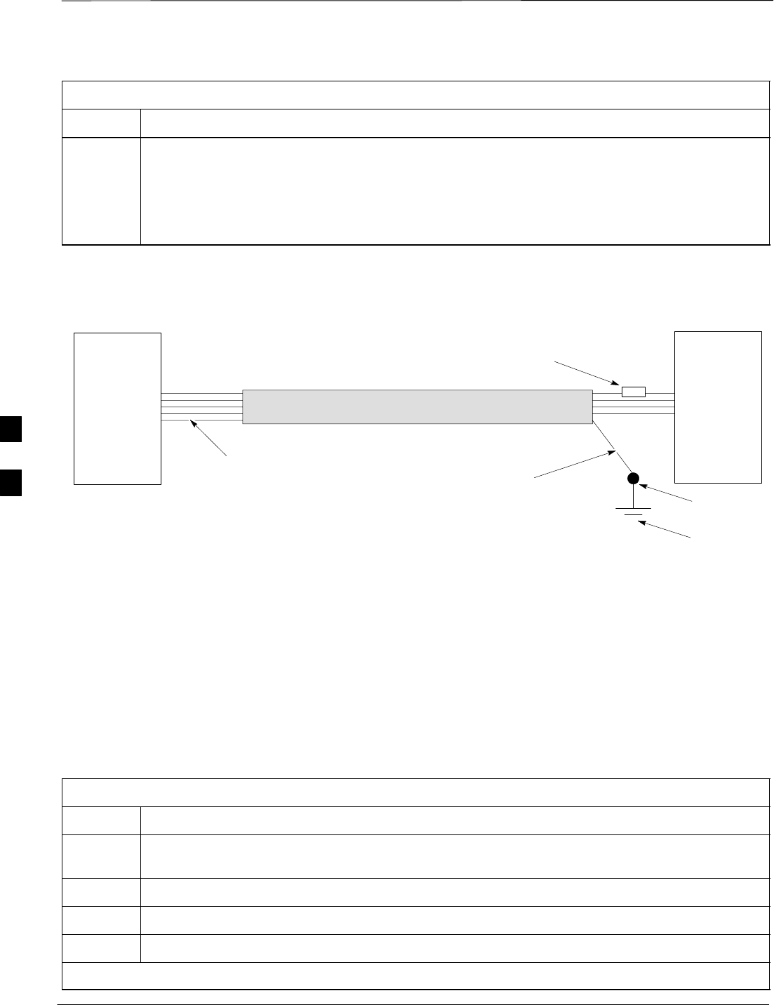
Figure 4-14 shows the general construction of the RGPS Sync Cable
(cable X). Cable X is supplied by Motorola with a 7.5 k Ohm, 1W
resistor already installed 150 mm from the end of the cable on the
blue/black wire. There is 200 mm on each end of the cable where the
jacketing has been cut back.
If necessary, the jacketing of cable X may be cut back further for proper
strain relief. For installations that require surge protection, you may cut
cable X at the dashed lines and insert the surge protection devices. Refer
to Table 4-29 for instructions to install the RGPS with surge protection.
Figure 4-14: RGPS Sync Cable Diagram
7.5 K OHM, 1W
RESISTOR
RGPS SYNC CABLE
LOOSE WIRES LOOSE WIRES
CABLE JACKET
200mm
150mm
5M MAX5M MAX 5M MAX5M MAX
Procedure to Install RGPS
Cabling for an Indoor
Installation
Use the procedure in Table 4-28 to connect the RGPS Sync cable for an
indoor installation. Refer to the cable run list in Table 4-31, Figure 4-18,
and Figure 4-19.
Table 4-28: Procedure to Install RGPS Cabling for an Indoor Installation
Step Action
1Connect the resistor end of the RGPS Sync Cable (cable X) to the sync reverse lines on the Site
I/O interface of BTS N. Refer to Figure 4-15. Refer to Table 4-31 for the cable X pinouts .
2Connect the drain wire of cable X to a lug terminal tied directly to the master ground (earth
ground) of BTS N.
3Route cable X from BTS N to BTS N+1.
. . . continued on next page
4
RGPS Cabling for Multiple BTS Sites – continued
DRAFT
SCt300 1X BTS Hardware Installation, ATP, and FRU Procedures JAN 2002
4-26
Table 4-28: Procedure to Install RGPS Cabling for an Indoor Installation
Step Action
4Remove excess cable length from cable X and terminate to the sync forward lines on the Site I/O
interface of BTS N+1. Refer to Table 4-31 for the cable X pinouts. Do not terminate the drain
wire to the ground at the Site I/O interface at BTS N+1.
wire to the ground at the Site I/O interface at BTS N+1.
NOTE
If necessary for proper strain relief, the jacketing of cable X may be cut back further.
Figure 4-15: RGPS Sync Cable for Indoor Installation
SITE I/O
INTERFACE SITE I/O
INTERFACE
BTS N
BTS N+1
7.5 K OHM, 1W RESISTOR
ATTACH DRAIN WIRE
TO MASTER GROUND
OF BTS N ONLY
RGPS SYNC CABLE
LOOSE WIRES
LUG TERMINAL
MASTER
GROUND
Procedure to Install RGPS
Cabling for an Outdoor
Installation
Use the procedure in Table 4-29 to install the RGPS cabling for any
installation that may be susceptible to surges or where any portion of the
RGPS cable is routed outside. In these cases, you must reduce the
length of the RGPS cable by (still to be determined length) to
accommodate for the additional timing error incurred by adding surge
protection.
Table 4-29: Procedure to Install RGPS Cabling for an Outdoor Installation
Step Action
1Follow all of the procedures in the “Connect RGPS Cables for Indoor Installation” procedure in
Table 4-28.
2Cut cable X to a maximum distance of 5m from BTS N.
3Install the surge protection device at this point, with the protected side towards BTS N.
4Ground the surge protection device to the master ground of BTS N.
. . . continued on next page
4
RGPS Cabling for Multiple BTS Sites – continued
JAN 2002 4-27
SCt300 1X BTS Hardware Installation, ATP, and FRU Procedures
DRAFT
Table 4-29: Procedure to Install RGPS Cabling for an Outdoor Installation
Step Action
5When you cut the cable in step 2, the jacketing for the portion of cable X on the unprotected side
of the surge suppressor is not grounded. To ground this portion of cable X, connect the drain wire
to a lug terminal tied directly to the master ground of BTS N.
NOTE
Only ground the end of the cable jacket at BTS N. Do not ground the jacket at BTS N+1. Refer
to Figure 4-16.
6Cut cable X to a maximum distance of 5m from BTS N+1.
7Ground the surge protection device to the master ground of BTS N+1.
8When you cut cable X in step 6, the jacketing for the portion of cable X between BTS N+1 and
the newly–inserted surge protector is ungrounded. To ground this portion of cable X, connect the
drain wire from one end of the jacket of the cable to a lug terminal tied directly to the master
ground of BTS N+1. Refer to Figure 4-16.
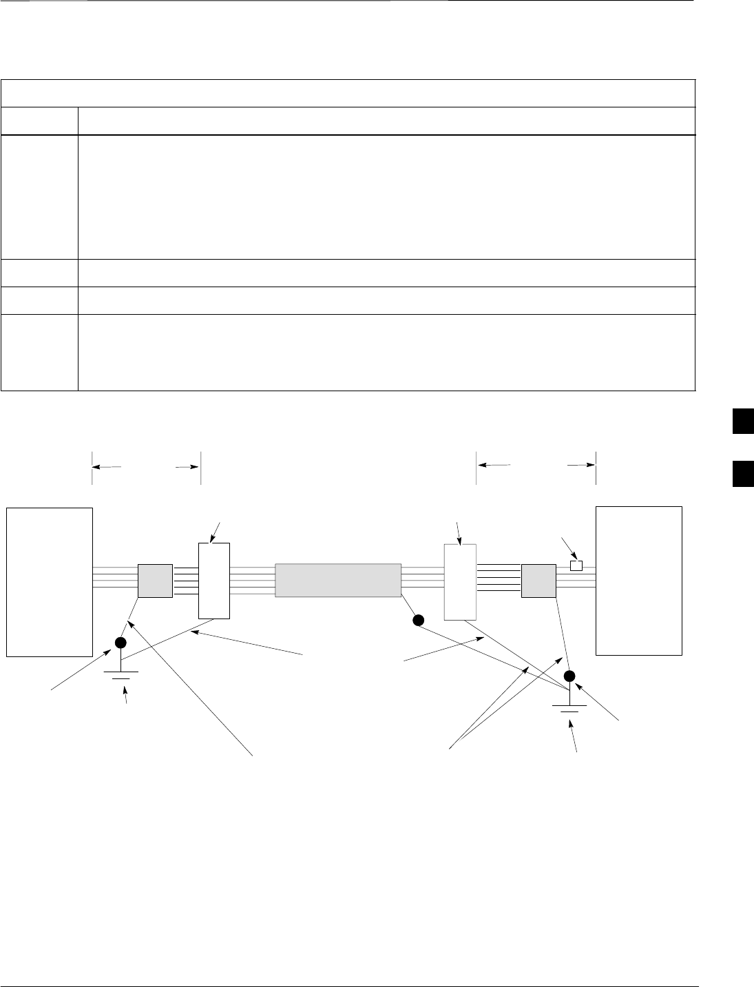
Figure 4-16: RGPS Sync Cable for Outdoor Installations
SITE I/O
INTERFACE
BTS N
BTS N+1
7.5 K OHM, 1W
RESISTOR
Attach the drain wires to the earth grounds. The
length of cable between surge suppressors should
be attached to the earth ground at BTS N only.
RGPS SYNC CABLE SITE I/O
INTERFACE
SURGE
SUPPRESSOR
SURGE
SUPPRESSOR
Ground the surge
suppressors to the
master grounds at each
BTS
5M MAX
MASTER
GROUND
BTS N+1
MASTER
GROUND
BTS N
5M MAX
LUG
TERMINAL
LUG
TERMINAL
Outdoor installation exceptions
In cases where it is impossible or impractical to route cable X in a
continuous stretch from BTS N to BTS N+1, you may cut and rejoin the
cable using an inline splice (solder or crimp). Both types of connections
are acceptable as long as each wire remains electrically isolated from
every other wire. The twisted pairs must be kept together. Refer to
Table 4-30 for the pairing of the twisted pairs.
4
RGPS Cabling for Multiple BTS Sites – continued
DRAFT
SCt300 1X BTS Hardware Installation, ATP, and FRU Procedures JAN 2002
4-28
You must splice the drain wire as well. Apply a weatherproof heat
shrink tubing or another weatherproof covering over the cable bundle in
the spliced section. Refer to Figure 4-17.
Figure 4-17: Cutting and Splicing RGPS Sync Cable
Splice each wire including the
drain wire.
Shrink wrap entire spliced area
Table 4-30: Twisted Pairs for RGPS Sync Cable (Cable X)
Pair Color
1Red/Black
Red
2White/Black
White
3Green/Black
Green
4Blue/Black
Blue
5Yellow/Black
Yellow
6Brown/Black
Brown
4

RGPS Cabling for Multiple BTS Sites – continued
JAN 2002 4-29
SCt300 1X BTS Hardware Installation, ATP, and FRU Procedures
DRAFT
Cable Connections
For a full signal description of the Site I/O cable, refer to Table 4-23 in
the “Site I/O, Span Line, RGPS and Modem Cabling” procedure.
The wire colors are based on the Site I/O cable.
NOTE
Table 4-31: Multi–BTS Cable Run List
Site I/O Interface of BTS N
(Sync Reverse) Interconnecting
Cable
(Cable X)
Site I/O Interface of BTS N+1
(Sync Forward)
Color Signal RGPS Cable
Color Color Signal
Black/Purple Data to Tail–Green/Black Brown/Grey Data from Head–
Black/Grey Data to Tail+ Green Brown/White Data from Head+
Black/White Data from Tail–White/Black Red/Black Data to Head–
Brown/Black Data from Tail+ White Red/Brown Data to Head+
Brown/Red 1 PPS to Tail–Brown/Black Red/Orange 1 PPS from Head–
Brown/Orange 1 PPS to Tail+ Brown Red/Yellow 1 PPS from Head+
Brown/Yellow 1 PPS from Tail–Red/Black Red/Green 1 PPS to Head–
Brown/Green 1 PPS from Tail+ Red Red/Blue 1 PPS to Head+
Black/Blue Ground* Blue/Black Black/Blue Ground*
*The Multi–BTS Synchronization interface must also be referenced to the BTS digital ground through a 7.5K
ohm, 1W resistor. This resistor has been integrated into the blue/black wire of Cable X. The end of Cable X
with the resistor should be connected to the Sync Reverse locations on the punch block of BTS N. The
opposite end of Cable X is connected to the Sync Forward locations on the punch block of BTS N+1 and may
be cut to the appropriate length.
4
RGPS Cabling for Multiple BTS Sites – continued
DRAFT
SCt300 1X BTS Hardware Installation, ATP, and FRU Procedures JAN 2002
4-30
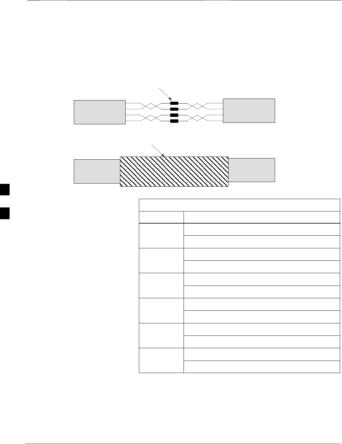
Figure 4-18: Site I/O Interface Cabling for RGPS (Synchronous) Configurations
CUSTOMER
INPUTS
SPAN
RGPS
PHONE
(MODEM)
SITE I/O
INTERFACE
SITE I/O
CABLE
CUSTOMER
INPUTS
SPAN
PHONE
(MODEM)
SITE I/O
CABLE
CUSTOMER
INPUTS
SPAN
PHONE
(MODEM)
SITE I/O
CABLE
CUSTOMER
INPUTS
SPAN
PHONE
(MODEM)
SITE I/O
CABLE
RGPS SYNC CABLE
RGPS SYNC CABLE
RGPS SYNC CABLE
NOTE 1: EACH BTS MAY CONTAIN UP TO
FOUR SC300 UNITS.
NOTE 2: A MAXIMUM OF 12 BTS MAY BE
INTERCONNECTED WITH A MAXIMUM
DAISY CHAIN CABLE LENGTH OF 600M
BETWEEN EACH BTS. A MAXIMUM OF
SEVEN BTS MAY BE INTERCONNECTED
WITH A MAXIMUM DAISY CHAIN CABLE
LENGTH OF 1KM BETWEEN EACH BTS
FOR INSTALLATIONS EQUIPPED WITH
SURGE PROTECTION.
MAXIMUM
DISTANCE IS
1 KM (SEE
NOTE 2)
BTS 1
(SEE
NOTE 1)
BTS 3
(SEE NOTE 1)
BTS 4
(SEE
NOTE 1)
UNIT 1
UNIT 1
BTS 2
(SEE NOTE 1)
MAXIMUM
DISTANCE IS
1 KM (SEE
NOTE 2)
MAXIMUM
DISTANCE IS
1 KM (SEE
NOTE 2)
UPSTREAM
UPSTREAM
UPSTREAM
DOWNSTREAM
DOWNSTREAM
DOWNSTREAM
SITE I/O
INTERFACE
SITE I/O
INTERFACE
SITE I/O
INTERFACE
UNIT 301 UNIT 201 UNIT 101 UNIT 1
UNIT 201 UNIT 101 UNIT 1
UNIT 101
= SURGE PROTECTION DEVICE (OPTIONAL)
SITE I/O
SITE I/O
SITE I/O
SITE I/O
X
X
X
4
RGPS Cabling for Multiple BTS Sites – continued
JAN 2002 4-31
SCt300 1X BTS Hardware Installation, ATP, and FRU Procedures
DRAFT
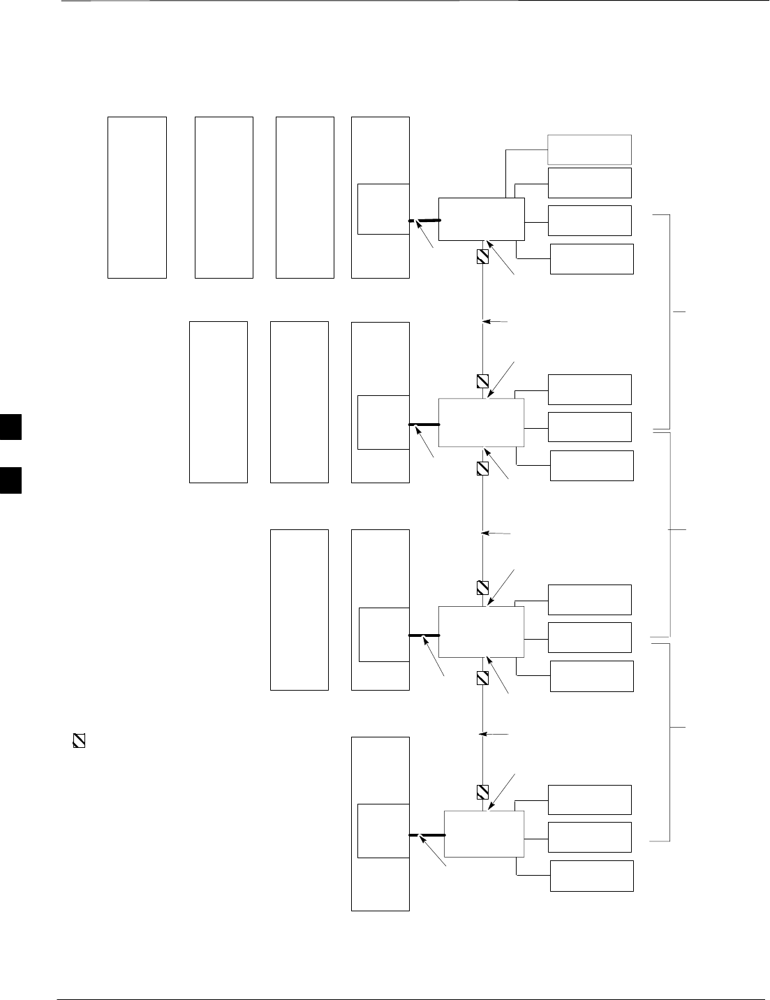
Figure 4-19: Site I/O Interface Cabling for HSO (Non–Synchronous) Configurations
CUSTOMER
INPUTS
SPAN
PHONE
(MODEM)
SITE I/O
INTERFACE
SITE I/O
CABLE
CUSTOMER
INPUTS
SPAN
PHONE
(MODEM)
SITE I/O
CABLE
CUSTOMER
INPUTS
SPAN
PHONE
(MODEM)
SITE I/O
CABLE
CUSTOMER
INPUTS
SPAN
PHONE
(MODEM)
SITE I/O
CABLE
RGPS SYNC CABLE
RGPS SYNC CABLE
RGPS SYNC CABLE
MAXIMUM
DISTANCE IS
600M (SEE
NOTE 2
BTS 1
(SEE
NOTE 1)
BTS 2
(SEE NOTE 1)
BTS 3
(SEE NOTE 1)
BTS 4
(SEE
NOTE 1)
UNIT 1
UNIT 1
UNIT 1
X
MAXIMUM
DISTANCE IS
600M (SEE
NOTE 2
MAXIMUM
DISTANCE IS
600M (SEE
NOTE 2
DOWNSTREAM
DOWNSTREAM
DOWNSTREAM
UPSTREAM
UPSTREAM
UPSTREAM
NOTE 1: EACH BTS MAY CONTAIN UP TO
FOUR SC300 UNITS.
NOTE 2: A MAXIMUM OF 12 BTS MAY BE
INTERCONNECTED WITH A MAXIMUM
DAISY CHAIN CABLE LENGTH OF 600M
BETWEEN EACH BTS. A MAXIMUM OF
SEVEN BTS MAY BE INTERCONNECTED
WITH A MAXIMUM DAISY CHAIN CABLE
LENGTH OF 1KM BETWEEN EACH BTS
FOR INSTALLATIONS EQUIPPED WITH
SURGE PROTECTION.
SITE I/O
INTERFACE
SITE I/O
INTERFACE
SITE I/O
INTERFACE
UNIT 301 UNIT 201 UNIT 101 UNIT 1
UNIT 201 UNIT 101
UNIT 101
= SURGE PROTECTION DEVICE (OPTIONAL)
SITE I/O
SITE I/O
SITE I/O
SITE I/O
X
X
4
Span Line Daisy Chain Cabling
DRAFT
SCt300 1X BTS Hardware Installation, ATP, and FRU Procedures JAN 2002
4-32
Objective
The objective of this procedure is to install span line cabling between
multiple BTS sites in an open daisy chain configuration.
Background
This feature allows up to 12 BTS sites to be linked together in an open
daisy chain loop using a single T1/E1 span. This will reduce the number
of spans necessary to support a CDMA system and minimize unused
channels.
Each multi–unit logical BTS may contain up to four units. A maximum
of 12 BTS sites may be combined in a single daisy chain.
Required Cables
The following cables in Table 4-32 are necessary to do this procedure.
Table 4-32: Required Cables for Span Line Daisy Chain Cabling
Cable Qty. Part Number Description
N 1–3 Customer
Supplied Span Line Daisy Chain Cable
Procedure
Attach the span line daisy chain cable (Cable N) to the site I/O interfaces
of each BTS. Refer to Figure 4-20 and Table 4-33.
Cable Connections
Table 4-33 shows the cable run information for span line daisy chain
cabling.
For a full signal description of the Site I/O cable refer to Table 4-23 in
the “Site I/O, Span Line, RGPS and Modem Cabling” procedure.
The pin number and wire color are based on the Site I/O
cable. The pin number corresponds to pins on the Site I/O
junction box connectors.
NOTE
Table 4-33: Cable Run List for Span Line Daisy Chain Cabling
BTS (Secondary Backhaul) BTS (Primary Backhaul)
Color Description Color Description
Yellow/Black RX TIP Orange/Grey TX TIP
Yellow/Brown RX RING Orange/White TX RING
Yellow/Red TX TIP Orange/Blue RX TIP
Yellow/Orange TX RING Orange/Purple RX RING
4
Span Line Daisy Chain Cabling – continued
JAN 2002 4-33
SCt300 1X BTS Hardware Installation, ATP, and FRU Procedures
DRAFT
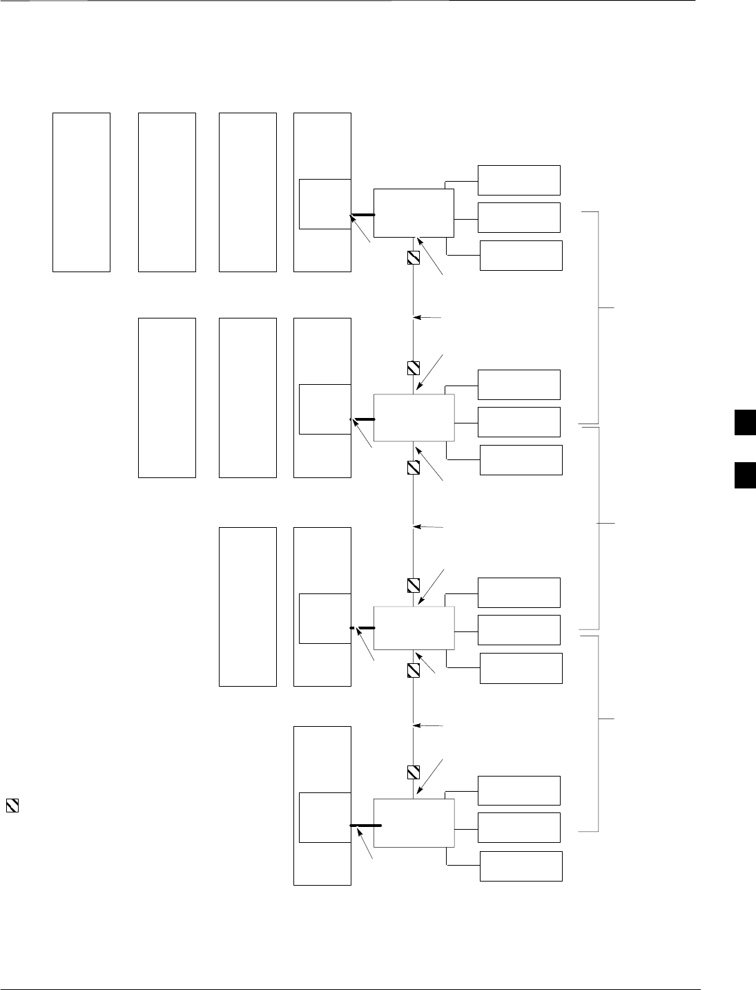
Figure 4-20: Site I/O Interface Cabling for Span Line Daisy Chain Cabling
CUSTOMER
INPUTS
SPAN
RGPS
PHONE
(MODEM)
SITE I/O
INTERFACE
SITE I/O
CABLE
CUSTOMER
INPUTS
PHONE
(MODEM)
SITE I/O
INTERFACE
SITE I/O
CABLE
CUSTOMER
INPUTS
PHONE
(MODEM)
SITE I/O
INTERFACE
SITE I/O
CABLE
CUSTOMER
INPUTS
PHONE
(MODEM)
SITE I/O
INTERFACE
SITE I/O
CABLE
BTS 1
(SEE NOTE 1)
SPAN LINE DAISY
CHAIN CABLE
SPAN LINE DAISY
CHAIN CABLE
SPAN LINE DAISY
CHAIN CABLE
N
N
N
BTS 2
(SEE NOTE 1)
BTS 3
(SEE NOTE 1)
BTS 4
(SEE NOTE 1)
UNIT 1UNIT 301 UNIT 201 UNIT 101
SITE I/O
UNIT 1UNIT 201 UNIT 101
SITE I/O
UNIT 1UNIT 101
SITE I/O
UNIT 1
SITE I/O
NOTE 1: EACH BTS SITE MAY
CONTAIN UP TO FOUR SC300 UNITS.
THERE MAY BE A TOTAL OF 12 BTSs IN
A DAISY CHAIN
NOTE 2: THE USE OF AN RGPS IS
DEPENDANT UPON WHETHER OR NOT
THE SITES USE A MULTI–BTS SITE
RGPS CONFIGURATION.
NOTE 3: THE USE OF THE MULTI–BTS
RGPS CABLE (CABLE X) DEPENDS
UPON SYSTEM CONFIGURATION.
RGPS
(SEE NOTE 2)
RGPS
(SEE NOTE 2)
RGPS
(SEE NOTE 2)
X/1
(SEE NOTE 3)
X/1
(SEE NOTE 3)
X/1
(SEE NOTE 3)
4

Span Line Daisy Chain Cabling – continued
DRAFT
SCt300 1X BTS Hardware Installation, ATP, and FRU Procedures JAN 2002
4-34
Notes
4

JAN 2002 SCt300 1X BTS Hardware Installation, ATP, and FRU Procedures
DRAFT
Chapter 5: Preparing Site Cabling for Sites Equipped with
Optional Primary Surge Suppressor
Table of Contents
Cabling Overview 5-1. . . . . . . . . . . . . . . . . . . . . . . . . . . . . . . . . . . . . . . . . . . . . . . .
Overview 5-1. . . . . . . . . . . . . . . . . . . . . . . . . . . . . . . . . . . . . . . . . . . . . . . .
Configurations Supported 5-1. . . . . . . . . . . . . . . . . . . . . . . . . . . . . . . . . . .
Cabling Installation Order 5-1. . . . . . . . . . . . . . . . . . . . . . . . . . . . . . . . . . .
Cable Labels 5-1. . . . . . . . . . . . . . . . . . . . . . . . . . . . . . . . . . . . . . . . . . . . .
Site Cabling for BTS With Optional Primary Surge Suppressor 5-2. . . . . . . . . . . .
Preparing Site Cabling Scope of Work 5-2. . . . . . . . . . . . . . . . . . . . . . . . .
Attaching the Surge Suppressor to Mounting Bracket 5-6. . . . . . . . . . . . . . . . . . . .
Objective 5-6. . . . . . . . . . . . . . . . . . . . . . . . . . . . . . . . . . . . . . . . . . . . . . . .
Background 5-6. . . . . . . . . . . . . . . . . . . . . . . . . . . . . . . . . . . . . . . . . . . . . .
Required Tools and Equipment 5-6. . . . . . . . . . . . . . . . . . . . . . . . . . . . . . .
Procedure to Attach the Surge Suppressor to the Mounting Bracket 5-6. .
Power, Ground, and Battery Cabling for Sites Equipped with
Optional Primary Surge Suppressor 5-8. . . . . . . . . . . . . . . . . . . . . . . . . . . . . . . . . .
Objective 5-8. . . . . . . . . . . . . . . . . . . . . . . . . . . . . . . . . . . . . . . . . . . . . . . .
Other Grounding Considerations 5-8. . . . . . . . . . . . . . . . . . . . . . . . . . . . . .
Power Considerations and Configurations 5-8. . . . . . . . . . . . . . . . . . . . . .
Required Cables 5-9. . . . . . . . . . . . . . . . . . . . . . . . . . . . . . . . . . . . . . . . . . .
AC Input Cable Information 5-9. . . . . . . . . . . . . . . . . . . . . . . . . . . . . . . . .
DC Input Cable Information 5-10. . . . . . . . . . . . . . . . . . . . . . . . . . . . . . . . .
Procedures to Install the Ground and Power Cabling 5-10. . . . . . . . . . . . . .
Antenna Cabling for Sites Equipped With Optional Primary Surge Suppressor 5-13
Objective 5-13. . . . . . . . . . . . . . . . . . . . . . . . . . . . . . . . . . . . . . . . . . . . . . . .
Cable Labels 5-13. . . . . . . . . . . . . . . . . . . . . . . . . . . . . . . . . . . . . . . . . . . . .
Required Cables 5-13. . . . . . . . . . . . . . . . . . . . . . . . . . . . . . . . . . . . . . . . . . .
Antenna Cable Pin and Signal Information 5-13. . . . . . . . . . . . . . . . . . . . . .
Procedure to Install Antenna Cabling for Sites Equipped with
Primary Surge Suppressor 5-14. . . . . . . . . . . . . . . . . . . . . . . . . . . . . . . . . . .
Site I/O, Span Line, RGPS, and Modem Cabling for Sites Equipped With
Primary Surge Suppressor 5-17. . . . . . . . . . . . . . . . . . . . . . . . . . . . . . . . . . . . . . . . .
Objective 5-17. . . . . . . . . . . . . . . . . . . . . . . . . . . . . . . . . . . . . . . . . . . . . . . .
Cable Labels 5-17. . . . . . . . . . . . . . . . . . . . . . . . . . . . . . . . . . . . . . . . . . . . .
Required Cables 5-17. . . . . . . . . . . . . . . . . . . . . . . . . . . . . . . . . . . . . . . . . . .
Site I/O Cabling 5-17. . . . . . . . . . . . . . . . . . . . . . . . . . . . . . . . . . . . . . . . . . .
Procedure to Install Site I/O Cable Between Site I/O Junction Box and
Optional Primary Surge Suppressor 5-18. . . . . . . . . . . . . . . . . . . . . . . . . . .
Pin and Signal Information for Surge Suppressor Punchdown
Block Cabling 5-20. . . . . . . . . . . . . . . . . . . . . . . . . . . . . . . . . . . . . . . . . . . .
5

Table of Contents – continued
DRAFT
SCt300 1X BTS Hardware Installation, ATP, and FRU Procedures JAN 2002
Connecting Customer–Defined Inputs to the Primary Surge Suppressor 5-22
Connecting the RGPS Cable to the Primary Surge Suppressor 5-23. . . . . .
Connecting the Span Line Cable to the Primary Surge Suppressor 5-23. . .
Connecting a Phone Line to the Primary Surge Suppressor
(Modem Support) 5-23. . . . . . . . . . . . . . . . . . . . . . . . . . . . . . . . . . . . . . . . . .
RGPS Cabling for Multiple BTS Sites Equipped with
Optional Primary Surge Suppressor 5-24. . . . . . . . . . . . . . . . . . . . . . . . . . . . . . . . . .
Objective 5-24. . . . . . . . . . . . . . . . . . . . . . . . . . . . . . . . . . . . . . . . . . . . . . . .
Background 5-24. . . . . . . . . . . . . . . . . . . . . . . . . . . . . . . . . . . . . . . . . . . . . .
Required Cables and Kits 5-24. . . . . . . . . . . . . . . . . . . . . . . . . . . . . . . . . . .
Cable Diagrams and Description 5-25. . . . . . . . . . . . . . . . . . . . . . . . . . . . . .
Procedure to Install RGPS Cabling for an Indoor Installation 5-25. . . . . . .
Procedure to Install RGPS Cabling for an Outdoor Installation 5-26. . . . . .
Cable Connections 5-29. . . . . . . . . . . . . . . . . . . . . . . . . . . . . . . . . . . . . . . . .
Span Line Daisy Chain Cabling for Multiple BTS Sites Equipped with
Optional Primary Surge Suppressor 5-32. . . . . . . . . . . . . . . . . . . . . . . . . . . . . . . . . .
Objective 5-32. . . . . . . . . . . . . . . . . . . . . . . . . . . . . . . . . . . . . . . . . . . . . . . .
Background 5-32. . . . . . . . . . . . . . . . . . . . . . . . . . . . . . . . . . . . . . . . . . . . . .
Required Cables 5-32. . . . . . . . . . . . . . . . . . . . . . . . . . . . . . . . . . . . . . . . . . .
Procedure 5-32. . . . . . . . . . . . . . . . . . . . . . . . . . . . . . . . . . . . . . . . . . . . . . . .
Cable Connections 5-32. . . . . . . . . . . . . . . . . . . . . . . . . . . . . . . . . . . . . . . . .
5

Cabling Overview
JAN 2002 5-1
SCt300 1X BTS Hardware Installation, ATP, and FRU Procedures
DRAFT
Overview
This chapter provides the procedures to prepare the BTS site cabling for
sites equipped with the optional Primary Surge Suppressor. Chapter 6
shows the scope of work for unit cabling.
You will connect the cables to the site and route them to the location of
the BTS. You will attach the cables to the unit during the unit cabling
procedures in Chapter 6.
Repeat cabling installation as necessary for each unit at the BTS.
Cabling is one of the most noticeable aspects of
workmanship. Straight runs and proper turns are critical for
a positive evaluation of the work.
NOTE
Configurations Supported
This chapter supports cable installation for single carrier omni
configurations and multi–carrier omni configurations. This chapter
supports cable installations for sites equipped with the optional Primary
Surge Suppressor.
Cabling Installation Order
To install the cables, Motorola recommends that the following
procedures be completed in the order shown:
1. Earth ground cabling
2. AC power cabling
3. DC power cabling
4. Battery cabling (optional)
5. Antenna cabling
6. Site I/O interface cabling
7. RGPS/HSO cabling (optional)
8. Span line daisy chain cabling (optional)
Cable Labels
The “Cable Descriptions and Part Numbers” in Table 4-1 provides cable
descriptions and part numbers. The labels used to designate the cables
(A, B, C, etc.) are used throughout this manual.
5
Site Cabling for BTS With Optional Primary Surge Suppressor
DRAFT
SCt300 1X BTS Hardware Installation, ATP, and FRU Procedures JAN 2002
5-2
Preparing Site Cabling Scope
of Work
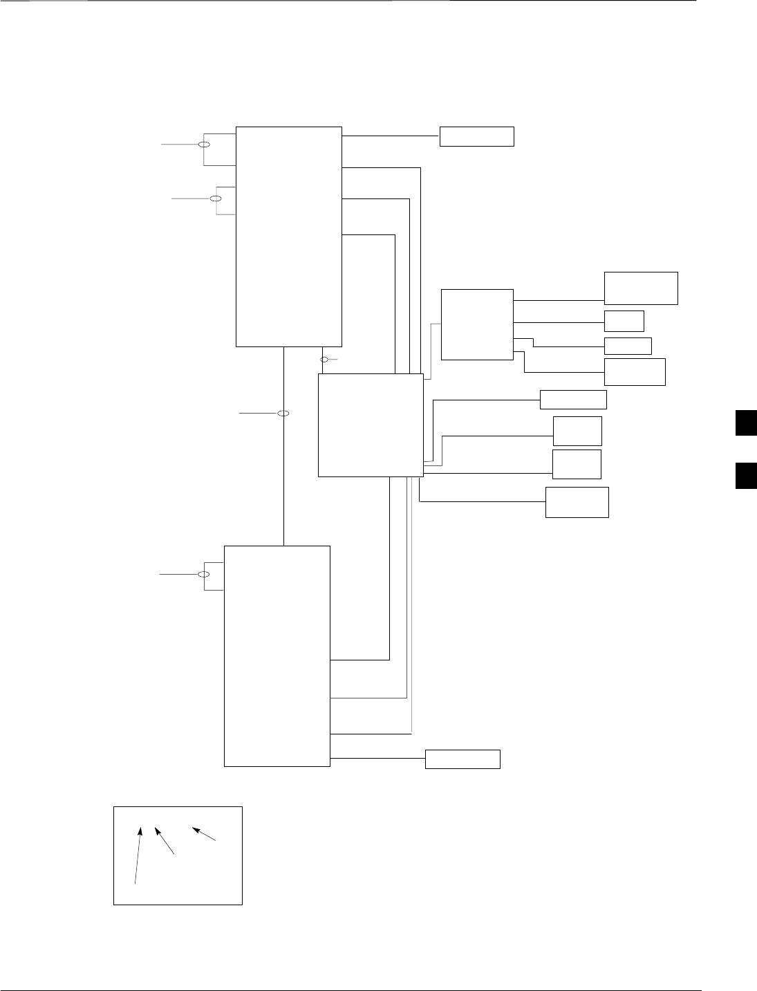
Figure 5-1 through Figure 5-4 shows the scope of work to be performed
for preparing the site cabling with the optional Primary Surge
Suppressor. Chapter 6 shows the scope of work for unit cabling.
Figure 5-1: Site Cabling for One MicroCell with Primary Surge Suppressor
MICROCELL 1
CUSTOMER
INPUTS
SPAN
RGPS
PHONE
(MODEM)
ANT A
RX
DC POWER
KEY
B/1(ANTENNA)
LABEL
NUMBER
OF CABLES
NAME
A/1(GROUND)
U/1(DC POWER)
SITE I/O
CABLE
P/1 (SU)
M/1 (RGPS)
N/1 (SPAN)
O/1 (CUSTOMER
INPUTS)
V/1 (PHONE)
AC POWER
T/1(AC POWER)
C/1 (ANTENNA)
PRIMARY
SURGE
SUPPRESSOR
D/1
(ANTENNA)
S/1 (AC
POWER)
MASTER
GROUND
Y/1 (MASTER
GROUND)
D/1
(ANTENNA)
ANT B
TX/RX
C/1 (ANTENNA)
B/1 (GROUND)
SITE I/O
INTERFACE
5
Site Cabling for BTS With Optional Primary Surge Suppressor – continued
JAN 2002 5-3
SCt300 1X BTS Hardware Installation, ATP, and FRU Procedures
DRAFT
Figure 5-2: Site Cabling for Two MicroCells with Primary Surge Suppressor
MICROCELL 1
MICROCELL 2
DC POWER
KEY
B/1(ANTENNA)
LABEL
NUMBER
OF CABLES
NAME
A/1(GROUND)
U/1(DC POWER)
E/1 (MIB) OR
K/1 (MIB)
SITE I/O
CABLE
DC POWER
U/1(DC POWER)
A/1(GROUND)
PRIMARY
SURGE
SUPPRESSOR
D/1
(ANTENNA 2)
S/1(AC
POWER)
D/1
(ANTENNA 1)
S/1 (AC
POWER)
B/1 (GROUND)
CUSTOMER
INPUTS
SPAN
RGPS
PHONE
(MODEM)
M/1 (RGPS)
N/1 (SPAN)
O/1 (CUSTOMER
INPUTS)
V/1 (PHONE)
SITE I/O
INTERFACE
ANT A
RX
AC POWER
T/1(AC POWER)
C/1 (ANTENNA)
MASTER
GROUND
Y/1 (MASTER
GROUND)
ANT B
TX/RX
C/1 (ANTENNA)
P/1 (SU)
P/1 (SU)
5
Site Cabling for BTS With Optional Primary Surge Suppressor – continued
DRAFT
SCt300 1X BTS Hardware Installation, ATP, and FRU Procedures JAN 2002
5-4
Figure 5-3: Site Cabling for Three MicroCells with Primary Surge Suppressor
MICROCELL 1
MICROCELL 3 MICROCELL 2
DC POWER
KEY
B/1(ANTENNA)
LABEL
NUMBER
OF CABLES
NAME
A/1(GROUND)
U/1(DC POWER)
F/1 (MIB) OR
I/1 (MIB)
SITE I/O
CABLE
DC POWER
U/1(DC POWER)
DC POWER
U/1(DC POWER)
A/1(GROUND)
PRIMARY
SURGE
SUPPRESSOR
D/1
(ANTENNA 2)
S/1(AC
POWER)
D/1
(ANTENNA 1)
S/1 (AC
POWER)
A/1(GROUND)
D/1
(ANTENNA 4)
S/1
(AC POWER)
D/1
(ANTENNA 3)
B/1 (GROUND)
E/1 (MIB) OR
K/1 (MIB)
ANT A
RX
AC POWER
T/1(AC POWER)
C/1 (ANTENNA)
MASTER
GROUND
Y/1 (MASTER
GROUND)
ANT B
TX/RX
C/1 (ANTENNA)
CUSTOMER
INPUTS
SPAN
RGPS
PHONE
(MODEM)
M/1 (RGPS)
N/1 (SPAN)
O/1 (CUSTOMER
INPUTS)
V/1 (PHONE)
SITE I/O
INTERFACE
P/1 (SU)
P/1 (SU)
P/1 (SU)
5
Site Cabling for BTS With Optional Primary Surge Suppressor – continued
JAN 2002 5-5
SCt300 1X BTS Hardware Installation, ATP, and FRU Procedures
DRAFT
Figure 5-4: Site Cabling for Four MicroCells with Primary Surge Suppressor
MICROCELL 4 MICROCELL 1
MICROCELL 3 MICROCELL 2
DC POWER
KEY
B/1(ANTENNA)
LABEL
NUMBER
OF CABLES
NAME
A/1(GROUND)
U/1(DC POWER)
G/1 (MIB) OR
J/1 (MIB)
SITE I/O
CABLE
DC POWER
U/1(DC POWER)
DC POWER
U/1(DC POWER)
DC POWER
U/1(DC POWER)
A/1(GROUND)
A/1(GROUND)
PRIMARY
SURGE
SUPPRESSOR
D/1
(ANTENNA 2)
S/1(AC
POWER)
D/1
(ANTENNA 1)
S/1 (AC
POWER)
A/1(GROUND)
D/1
(ANTENNA 3)
S/1
(AC POWER)
D/1 (ANTENNA 4)
S/1 (AC POWER)
B/1
(GROUND)
E/1 (MIB) OR
K/1 (MIB)
E/1 (MIB) OR
K/1 (MIB)
F/1 (MIB) OR
I/1 (MIB)
CUSTOMER
INPUTS
SPAN
RGPS
PHONE
(MODEM)
M/1 (RGPS)
N/1 (SPAN)
O/1 (CUSTOMER
INPUTS)
V/1 (PHONE)
SITE I/O
INTERFACE
ANT A
RX
AC POWER
T/1(AC POWER)
C/1 (ANTENNA)
MASTER
GROUND
Y/1 (MASTER
GROUND)
ANT B
TX/RX
C/1 (ANTENNA)
P/1 (SU)
P/1 (SU)
P/1 (SU)
P/1 (SU)
5
Attaching the Surge Suppressor to Mounting Bracket
DRAFT
SCt300 1X BTS Hardware Installation, ATP, and FRU Procedures JAN 2002
5-6
Objective
The objective of this procedure is to attach the optional Primary Surge
Suppressor to the mounting bracket. This procedure applies to mounting
brackets that are attached to a rack, wall or pole.
You must attach the Primary Surge Suppressor to the
mounting bracket before you install the unit cabling.
IMPORTANT
*
Background
The following procedures should be followed in order to mount the
surge suppressor to the mounting bracket. The unit attaches to the
mounting bracket with three (3) M6 screws.
Required Tools and Equipment
The following tools and materials are required to attach the unit to the
mounting bracket.
STorque driver wrench, 1/4–in. hex female drive, 0–10 N–M
ST30 Torx tamper bit
SThree M6X19 screws (Motorola Part Number 0387541C03)
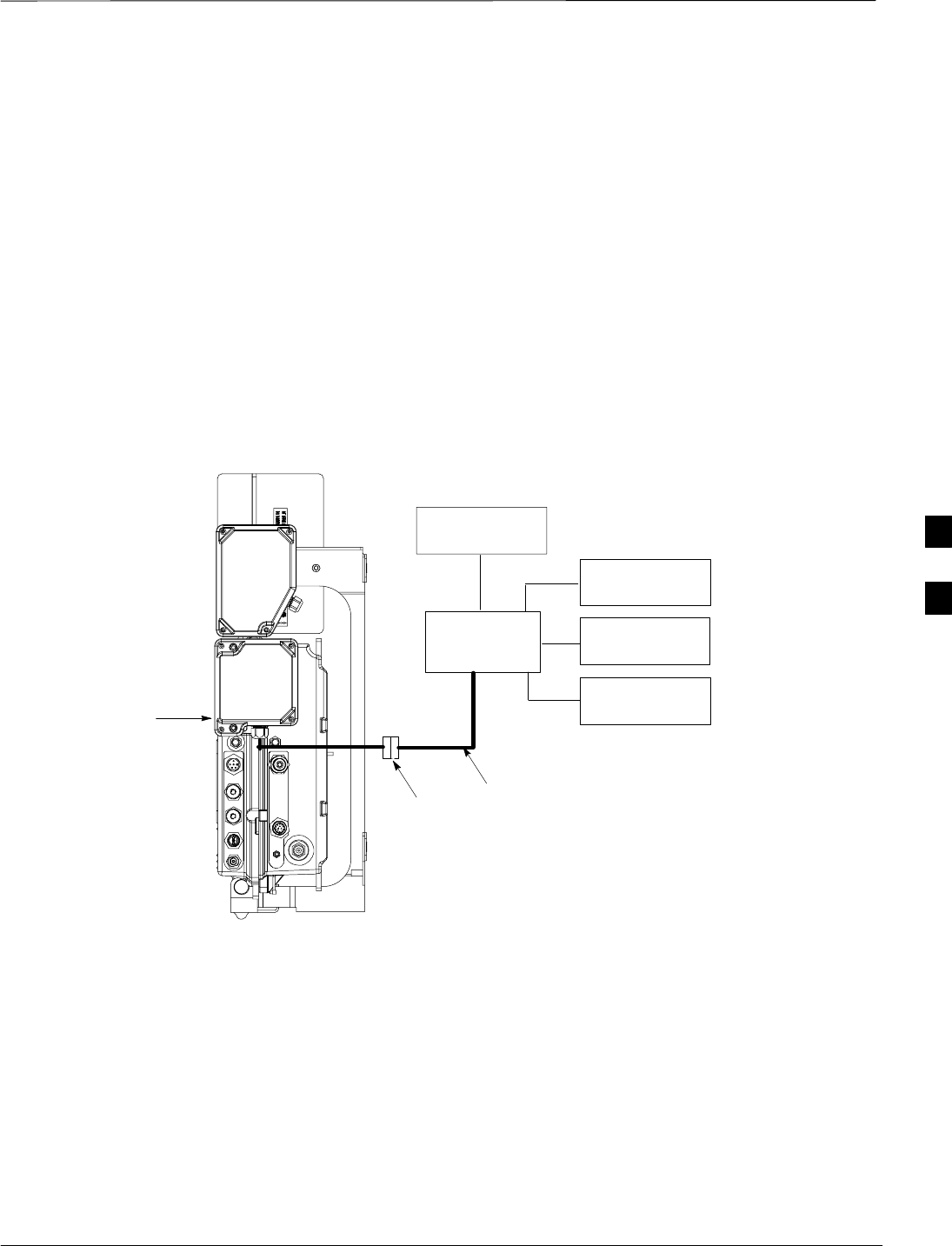
Procedure to Attach the Surge
Suppressor to the Mounting
Bracket
Use the procedure in Table 5-1 to attach the surge suppressor to the
mounting bracket. Refer to Figure 5-5.
Table 5-1: Procedure to Attach the Surge Suppressor to the Mounting Bracket
Step Action
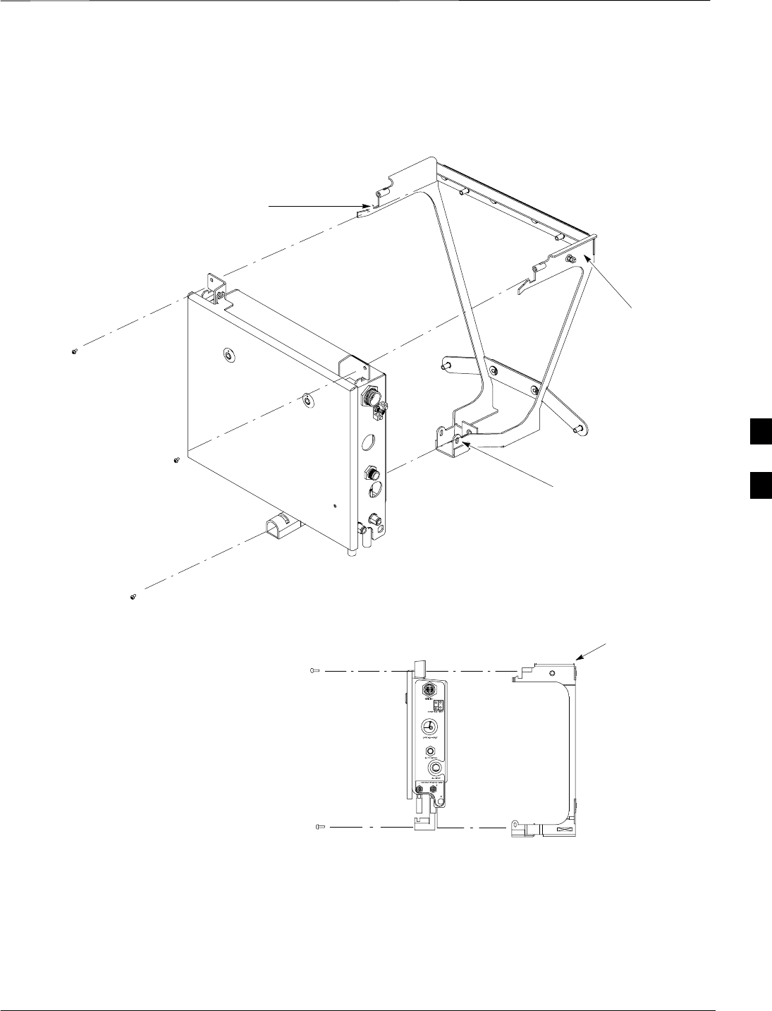
1Lift the unit and place it on the mounting bracket by aligning the bracket’s upper arms into the
rectangular cutouts in the mounting tabs. The unit may need to be raised up slightly so that the
lower bracket flange does not contact the unit’s lower surface.
2Use a T30 Torx tamper bit to start, but not tighten, all three screws in the location shown in
Figure 5-5.
3Use a T30 Torx tamper bit to torque the three mounting screws to 5.0 N–M.
5
Attaching the Surge Suppressor to Mounting Bracket – continued
JAN 2002 5-7
SCt300 1X BTS Hardware Installation, ATP, and FRU Procedures
DRAFT
Figure 5-5: Attaching the Surge Suppressor to the Mounting Bracket
HOOKS
MOUNTING BRACKET
SLIDE CUSTOMER–SUPPLIED
PADLOCK THROUGH HOLES IN
BRACKET (OPTIONAL)
MOUNTING BRACKET
M6 SCREWS (3)
5

Power, Ground, and Battery Cabling for Sites Equipped with Optional
Primary Surge Suppressor
DRAFT
SCt300 1X BTS Hardware Installation, ATP, and FRU Procedures JAN 2002
5-8
Objective
The objective of this procedure is to install the power, earth ground, and
battery cabling for one or more Microcell units at a site equipped with
optional Primary Surge Suppressor.
Dangerous voltages, capable of causing death, are present
in this equipment. Use extreme caution when handling and
testing this equipment.
WARNING
Other Grounding
Considerations
This procedure covers only the grounding information for the ground
cables that attach to one or more Microcell units. Grounding
considerations beyond the ground cables that attach to the Microcell are
summarized in Appendix A. Refer to Appendix A and the site
documentation for other grounding considerations.
Motorola recommends that you use an oxide inhibitor such
as Burndy PENETROXt or Ilsco DE–OXt on all the
external ground connections on the unit and on the primary
surge suppressor for all outdoor installations. This
includes the ground connections on the mounting bracket,
the Site I/O, and the five mechanical lugs on the primary
surge suppressor.
NOTE
Power Considerations and
Configurations
The Primary Surge Suppressor is designed for 120/240 VAC 3–wire plus
ground single phase 30 amp min. service.
The power and battery configurations for the MicroCell unit is:
SAC power only (no battery)
SAC power with short duration battery
SDC power
Neither the ”+” or ”–” terminal of the DC Input is
connected to the BTS ground. If a negative supply input is
provided, the ”+” terminal of the DC input must be
connected to the Master Ground Plate (MGP). By
connecting the ”+” terminal of the DC input to the MGP, a
negative supply system is created.
NOTE
5
Power, Ground, and Battery Cabling for Sites Equipped with Optional
Primary Surge Suppressor – continued
JAN 2002 5-9
SCt300 1X BTS Hardware Installation, ATP, and FRU Procedures
DRAFT
Required Cables
Table 5-2 provides the quantity and description of the required cables.
Table 5-2: Required Cables for Power, Earth Ground, and Battery Connections
Cable Qty. Part Number Description
A 1–4 3087701C02 Ground cable, 8 -AWG, insulated copper wire. Requires one ring lug
connector.
S 1–4 3087854C02 AC input cable, 14 AWG, 5 m, is designed for 88–260 VAC power
input. Cable has Deutsche connector on both ends.
T 1 Customer
Supplied AC Input power cable. 10–14 AWG, 90_C wire. Designed for
120–240 VAC.
U 1–4 3087854C04 DC input cable, 14 and 22 AWG, 5 m, is designed for 20 to 30 VDC
power input.
Y 1 Customer
Supplied Master Ground Cable, 6 -AWG, insulated copper wire.
AC Input Cable Information
The information for the AC input cable(s) (Cable S) is given in
Figure 5-6 and Table 5-3.
Figure 5-6: AC Input Cable Connector Information
A
BCSOCKET POSITION ON CABLE
CONNECTOR SHOWN
Table 5-3: AC Input Cable Information
Connector Wire Color Description
A Black Line
B Green Ground
C White Neutral
5
Power, Ground, and Battery Cabling for Sites Equipped with Optional
Primary Surge Suppressor – continued
DRAFT
SCt300 1X BTS Hardware Installation, ATP, and FRU Procedures JAN 2002
5-10
DC Input Cable Information
The information for the DC input cable(s) (Cable U) is given in
Figure 5-7 and Table 5-4.
Figure 5-7: DC Input Cable Connector Information
A
B
C
DSOCKET POSITION ON
CABLE CONNECTOR SHOWN
Table 5-4: DC Input Cable Information
Connector Wire
Color Description Comments
A Yellow Switch A No connection
B Red Positive Connect to positive
terminal of supply.
C Blue Switch B Connect to negative
terminal of supply.
D Black Negative Connect to negative
terminal of supply.
Procedures to Install the
Ground and Power Cabling
The system configuration determines which power cables are installed.
The ground cable is always installed. Based on the system configuration
perform the appropriate procedures from the following tables.
Table 5-5: Procedure to Install the Master Ground Cable on a BTS Equipped with Optional Primary Surge
Suppressor
Step Action
1Connect the Master Ground cable (cable Y) to the EARTH GND connector on the Primary Surge
Suppressor.
2Connect the other end of cable Y to the customer–defined master ground plate.
5

Power, Ground, and Battery Cabling for Sites Equipped with Optional
Primary Surge Suppressor – continued
JAN 2002 5-11
SCt300 1X BTS Hardware Installation, ATP, and FRU Procedures
DRAFT
Table 5-6: Procedure to Install the Earth Ground Cable on a BTS Equipped with Optional Primary Surge
Suppressor
Step Action
1Route cable A (ground cable) from the ground lug on the unit mounting bracket to the Primary
Surge Suppressor location.
2Connect cable A to the GND connector 1–4 on the Primary Surge Suppressor.
Table 5-7: Procedure to Install the AC Input Cable(s) on a BTS Equipped with Optional Primary Surge
Suppressor
Step Action
1Connect the customer–supplied AC input power cable (cable T) to the customer defined AC
power source. Refer to Table 5-3 for wiring information.
2Verify all connections of cable T with an ohmmeter prior to routing the cable.
3Route cable T via 1–in. conduit from the customer defined AC power source to the breaker
terminals inside the Primary Surge Suppressor. Refer to Figure 5-8.
4Place the round, black connector on the AC input power cable (cable S) onto the appropriate
Carrier 1–4 AC Output connector on the Primary Surge Suppressor.
5Route the AC input power cable (cable S – Motorola part number 3087854C02) from the Primary
Surge Suppressor to the unit location(s).
Table 5-8: Procedure to Install the DC Input Cable(s) on a BTS Equipped with Optional Primary Surge
Suppressor
Step Action
1Connect the loose wires of the DC Input Cable (cable U) to the customer defined DC power
source. Refer to Table 5-4 for wiring information.
2Verify all connections of cable U with an ohmmeter prior to routing the cable.
3Route cable U from the DC power supply to the unit location.
5
Power, Ground, and Battery Cabling for Sites Equipped with Optional
Primary Surge Suppressor – continued
DRAFT
SCt300 1X BTS Hardware Installation, ATP, and FRU Procedures JAN 2002
5-12
Figure 5-8: Primary Surge Suppressor AC Input Power Connection Locations
GROUND
NEUTRAL
INPUT LINE 1
INPUT LINE 2
1–IN CONDUIT
CUSTOMER
AC POWER
SOURCE
AC LOAD
CENTER ALARM
CONNECTION
3 2 1
ALARM WIRE
POSITIONS
5
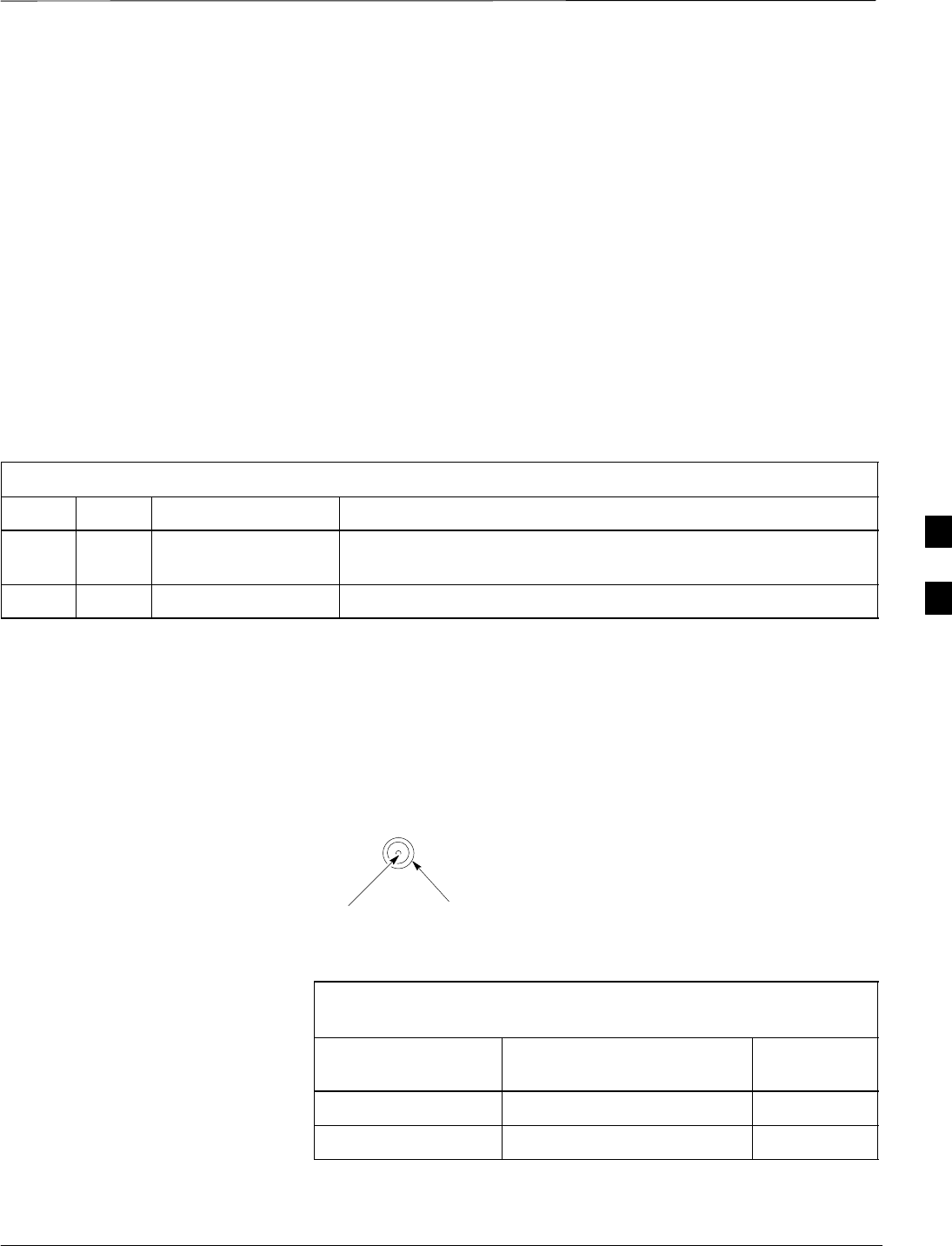
Antenna Cabling for Sites Equipped With Optional Primary Surge
Suppressor
JAN 2002 5-13
SCt300 1X BTS Hardware Installation, ATP, and FRU Procedures
DRAFT
Objective
The objective of this procedure is to install the cabling for the
antenna(s).
The antenna cabling is installed between one or more units and the
Primary Surge Suppressor. No lightning arrestors are used.
Cable Labels
The cable designations are referenced to Table 4-1 in the “Cable
Description” area of this chapter.
Required Cables
Table 5-9 provides the quantities and descriptions of the required cables.
Table 5-9: Required Cables for Antenna Connections
Cable Qty. Part Number Description
C1 to 8 Customer Supplied Antenna cable, 50–Ohm coaxial terminated with at least one male,
N–type connector.
D 2–6Customer Supplied Antenna cable, terminated with 2 N–type connectors
Antenna Cable Pin and Signal
Information
The antenna cabling uses a 50–Ohm coaxial cable. The inner conductor
provides signaling and the outer conductor provides shielding and
ground.
Figure 5-9: Antenna Cabling Details
OUTER
CONDUCTOR
INNER
CONDUCTOR
ANTENNA CABLE (COAXIAL)
CONNECTOR
Table 5-10: Pin and Signal Information for Cables C and D (Antenna
Cable)
Antenna Inner Conductor Outer
Conductor
B (Microcell only) TX/RX Ground
ARX (Microcell) Ground
5
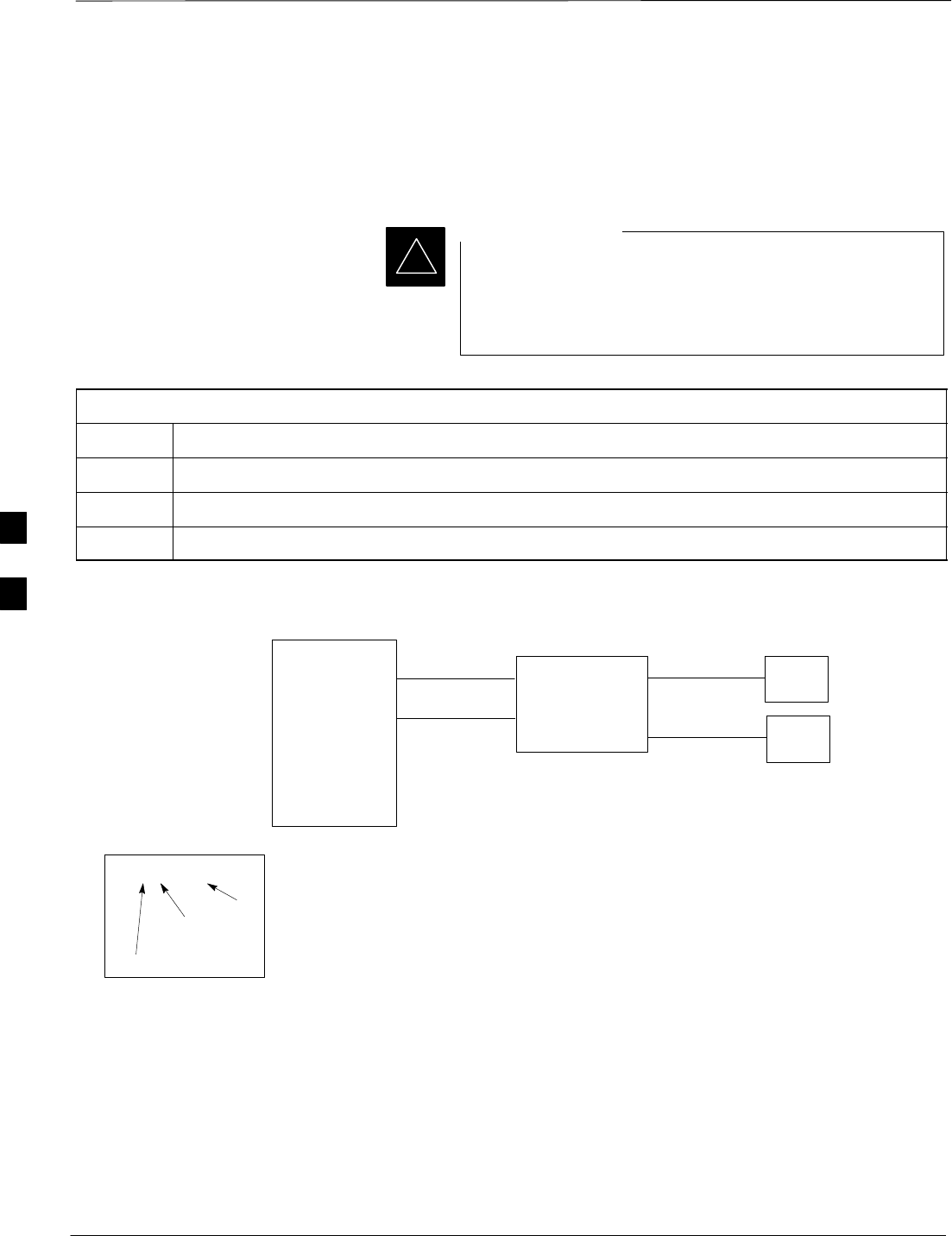
Antenna Cabling for Sites Equipped With Optional Primary Surge
Suppressor – continued
DRAFT
SCt300 1X BTS Hardware Installation, ATP, and FRU Procedures JAN 2002
5-14
Procedure to Install Antenna
Cabling for Sites Equipped
with Primary Surge Suppressor
Do the procedure in Table 5-11 to install the antenna cabling.
Lightning arrestors are installed on the Primary Surge
Suppressor for two units. You must add additional
lightning arrestors when you expand from one to two units;
two to three units and from three to four units.
IMPORTANT
*
Table 5-11: Procedure to Install Antenna Cabling for Sites Equipped with Primary Surge Suppressor
Step Action
1Route cable D (antenna cable) between the unit(s) and the Primary Surge Suppressor.
2Route cable C (antenna cable) from the Primary Surge Suppressor directly to the antenna(s).
3Torque connectors to 4.3 N–m.
Figure 5-10: Antenna Cabling for One Microcell with Primary Surge Suppressor
MICROCELL 1
KEY
B/1(ANTENNA)
LABEL
NUMBER
OF CABLES
NAME
D/1(ANTENNA)
PRIMARY SURGE
SUPPRESSOR
ANT A
RX
ANT B
TX/RX
D/1(ANTENNA) C/1(ANTENNA)
C/1(ANTENNA)
5
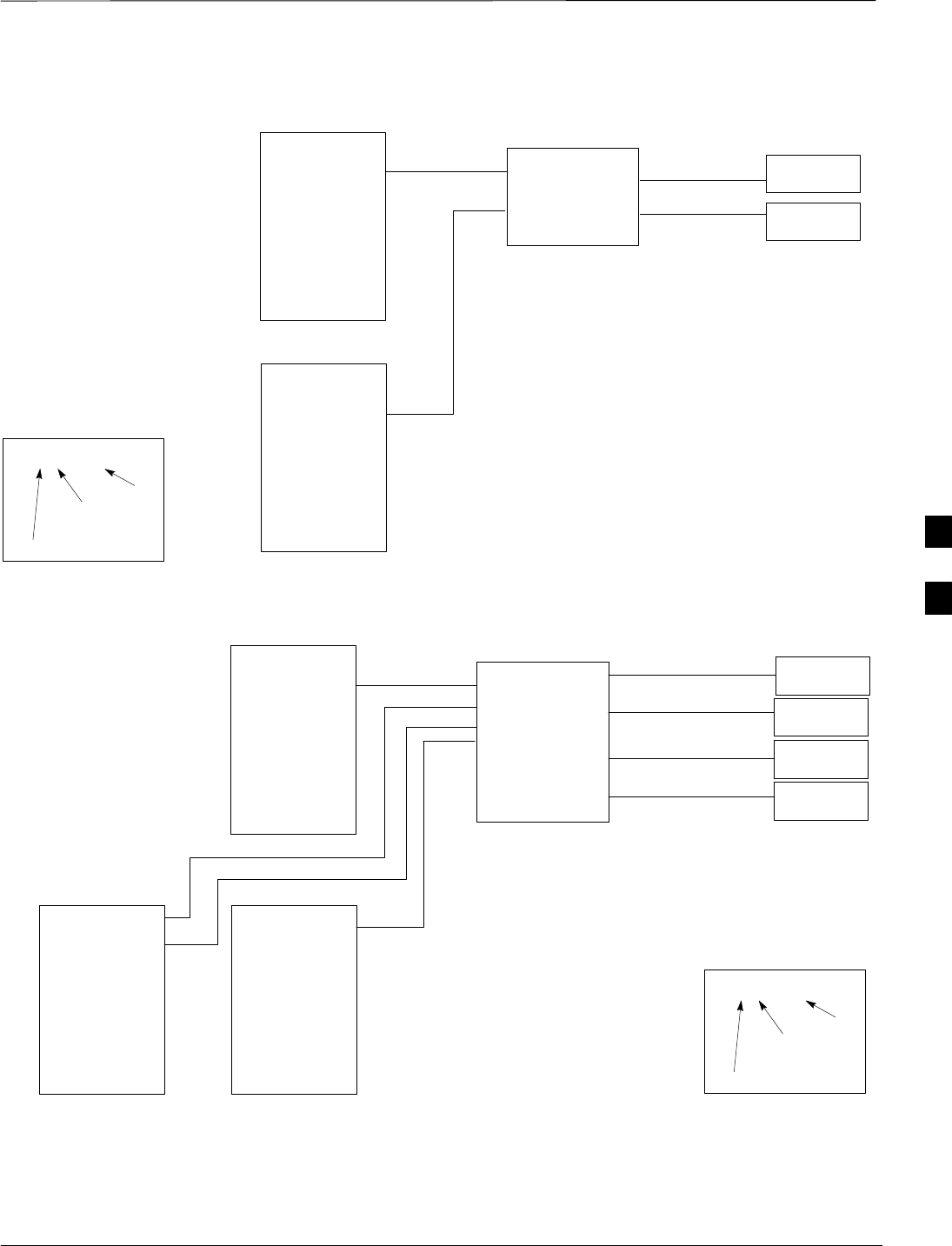
Antenna Cabling for Sites Equipped With Optional Primary Surge
Suppressor – continued
JAN 2002 5-15
SCt300 1X BTS Hardware Installation, ATP, and FRU Procedures
DRAFT
Figure 5-11: Antenna Cabling for Two Microcells with Primary Surge Suppressor
MICROCELL 1
KEY
B/1(ANTENNA)
LABEL
NUMBER
OF CABLES
NAME
D/1(ANTENNA)
PRIMARY SURGE
SUPPRESSOR
MICROCELL 2
D/1(ANTENNA)
ANTENNA 1
TX/RX
ANTENNA 2
TX/RX
C/1(ANTENNA)
C/1(ANTENNA)
Figure 5-12: Antenna Cabling for Three Microcells with Primary Surge Suppressor
MICROCELL 1
KEY
B/1(ANTENNA)
LABEL
NUMBER
OF CABLES
NAME
D/1(ANTENNA)
PRIMARY SURGE
SUPPRESSOR
MICROCELL 2
D/1(ANTENNA)
MICROCELL 3
D/1(ANTENNA)
D/1(ANTENNA)
ANTENNA 3
RX
ANTENNA 4
TX/RX
ANTENNA 2
TX/RX
ANTENNA 1
TX/RX
C/1(ANTENNA)
C/1(ANTENNA)
C/1(ANTENNA)
C/1(ANTENNA)
5
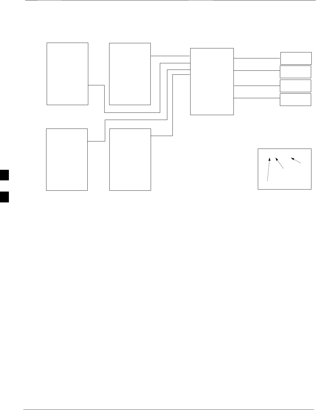
Antenna Cabling for Sites Equipped With Optional Primary Surge
Suppressor – continued
DRAFT
SCt300 1X BTS Hardware Installation, ATP, and FRU Procedures JAN 2002
5-16
Figure 5-13: Antenna Cabling for Four Microcells with Primary Surge Suppressor
MICROCELL 1
KEY
B/1(ANTENNA)
LABEL
NUMBER
OF CABLES
NAME
D/1(ANTENNA)
PRIMARY SURGE
SUPPRESSOR
MICROCELL 2
D/1(ANTENNA)
MICROCELL 3
D/1(ANTENNA)
D/1(ANTENNA)
MICROCELL 4
ANTENNA 3
TX/RX
ANTENNA 4
TX/RX
ANTENNA 2
TX/RX
ANTENNA 1
TX/RX
C/1(ANTENNA)
C/1(ANTENNA)
C/1(ANTENNA)
C/1(ANTENNA)
5

Site I/O, Span Line, RGPS, and Modem Cabling for Sites Equipped With
Primary Surge Suppressor
JAN 2002 5-17
SCt300 1X BTS Hardware Installation, ATP, and FRU Procedures
DRAFT
Objective
The objective of this procedure is to install the cabling between the Site
I/O junction box to the Primary Surge Suppressor. This procedure also
shows the punchblock cabling for the Site I/O cable.
Cable Labels
The cable designations are referenced to Table 4-1 in the “Cable
Description” area of this chapter.
Required Cables
Table 5-12 provides the quantities and descriptions of the required
cables.
Table 5-12: Required Cables for Antenna Connections
Cable Qty. Part Number Description
C 1–8Customer Supplied Antenna cable, 50–Ohm coaxial terminated with at least one male,
N–type connector.
D 2–6Customer Supplied Antenna cable, terminated with 2 N–type connectors
M 1 3086039H11 RGPS cable, 125 ft.
3086039H12 RGPS cable, 250 ft.
3086039H13 RGPS cable, 500 ft.
3086039H14 RGPS cable, 1000 ft.
3086039H15 RGPS cable, 2000 ft.
N 1 Customer Supplied Span Cable. 22–24 AWG solid copper twisted pair.
O 1 Customer Supplied Customer Input Cable. 22–24 AWG solid copper twisted pair.
T 1 Customer Supplied AC Input Power Cable. 14 AWG. Designed for 120–240 VAC.
Terminated by at least 1 Deutsche connector.
V 1 Customer Supplied Phone (Modem) Cable. 22–24 AWG solid copper twisted pair.
Site I/O Cabling
The Primary Surge Suppressor is optional and is supplied by Motorola.
The Site I/O cable between the Primary Surge Suppressor and units 1
and 2 is part of the Site I/O Junction box and is supplied by Motorola.
The customer determines the Primary Surge Suppressor configuration.
The end result is the correct signals getting to the correct punchblock
location on the punchdown block.
5
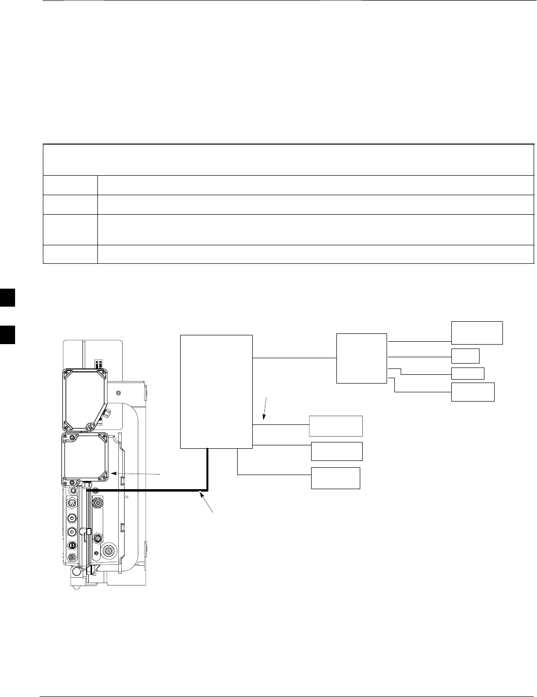
Site I/O, Span Line, RGPS, and Modem Cabling for Sites Equipped With
Primary Surge Suppressor – continued
DRAFT
SCt300 1X BTS Hardware Installation, ATP, and FRU Procedures JAN 2002
5-18
Procedure to Install Site I/O
Cable Between Site I/O
Junction Box and Optional
Primary Surge Suppressor
Do the procedure in Table 5-13 to connect the Site I/O cable. Refer to
Figure 5-14, Figure 5-15 and Figure 5-16.
Table 5-13: Procedure to Install Site I/O Cable Between Site I/O Junction Box and Optional Primary Surge
Suppressor
Step Action
1Route the Site I/O cable(s) from the unit location to the Primary Surge Suppressor.
2Connect the Site I/O cable from unit 1 to the connector labeled SITE I/O 1 on the right side of the
Surge Suppressor.
3Connect the appropriate conductors or wires to the Primary Surge Suppressor Punchdown block.
Figure 5-14: Site I/O Cabling Details with Primary Surge Suppressor
PRIMARY
SURGE
SUPPRESSOR
SITE I/O
JUNCTION
BOX
SITE I/O
CABLE
AC
POWER
T
ANTENNA
D
MASTER
GROUND
Y
MICROCELL 1 CUSTOMER
INPUTS
SPAN
RGPS
PHONE
(MODEM)
M
N
O
V
SITE I/O
INTERFACE
1–IN CONDUIT
(FOR CABLES O, N,
M, AND V)
1–IN CONDUIT
5
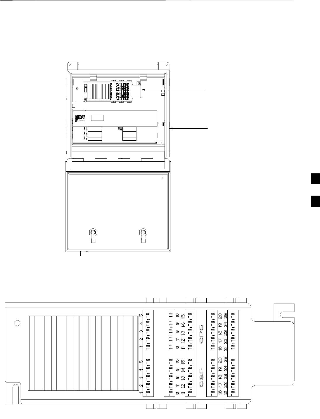
Site I/O, Span Line, RGPS, and Modem Cabling for Sites Equipped With
Primary Surge Suppressor – continued
JAN 2002 5-19
SCt300 1X BTS Hardware Installation, ATP, and FRU Procedures
DRAFT
Figure 5-15: Punchdown Block Location
PUNCHDOWN BLOCK
PRIMARY SURGE
SUPPRESSOR
Figure 5-16: Punchdown Block
5

Site I/O, Span Line, RGPS, and Modem Cabling for Sites Equipped With
Primary Surge Suppressor – continued
DRAFT
SCt300 1X BTS Hardware Installation, ATP, and FRU Procedures JAN 2002
5-20
Pin and Signal Information for
Surge Suppressor Punchdown
Block Cabling
Table 5-14 gives the pin and signal information for connecting the loose
wires to the customer locations on the Punchdown Block.
The “CPE” half of the punchdown block connectors comes
shipped pre–wired and complete. The user only needs to
wire the “OSP” half of the punchdown block connectors.
NOTE
Table 5-14: Pin/Signal Information for Site I/O Cable and Punchdown Block
BTS Interface Punchblock
Location Description
OSP 1T Customer Input 1 Signal
OSP 1R Customer Input 1 Ground
OSP 2T Customer Input 2 Signal
OSP 2R Customer Input 2 Ground
OSP 3T Customer Input 3 Signal
OSP 3R Customer Input 3 Ground
OSP 4T Customer Input 4 Signal
OSP 4R Customer Input 4 Ground
Customer Input OSP 5T Customer Input 5 Signal
OSP 5R Customer Input 5 Ground
OSP 6T Customer Input 6 Signal
OSP 6R Customer Input 6 Ground
OSP 7T Customer Input 7 Signal
OSP 7R Customer Input 7 Ground
OSP 8T Customer Input 8 Signal*
OSP 8R Customer Input 8 Ground*
OSP 9T Data to Tail –
OSP 9R Data to Tail +
Sync Reverse OSP 10T Data from Tail –
OSP 10R Data from Tail +
. . . continued on next page
5

Site I/O, Span Line, RGPS, and Modem Cabling for Sites Equipped With
Primary Surge Suppressor – continued
JAN 2002 5-21
SCt300 1X BTS Hardware Installation, ATP, and FRU Procedures
DRAFT
Table 5-14: Pin/Signal Information for Site I/O Cable and Punchdown Block
BTS Interface DescriptionPunchblock
Location
Sync Reverse OSP 11T 1 PPS to Tail –
OSP 11R 1 PPS to Tail +
OSP 12T 1 PPS from Tail –
Sync Reverse OSP 12R 1 PPS from Tail +
OSP 13T Downstream BTS Detect +
OSP 13R Downstream BTS Detect –
OSP 14T Data from Head –
OSP 14R Data from Head +
OSP 15T Data to Head –
OSP 15R Data to Head +
OSP 16T 1 PPS from Head –
OSP 16R 1 PPS from Head +
Sync Forward OSP 17T 1 PPS to Head –
OSP 17R 1 PPS to Head +
OSP 18T RGPS 28V
OSP 18R RGPS Ground
OSP 19T RGPS 28V
OSP 19R RGPS Ground
OSP20T Unused
Unused OSP20R Unused
OSP 21T RX TIP Primary (Network/Span A)
OSP 21R RX RING Primary (Network/Span A)
OSP 22T TX TIP Primary (Network/Span A)
Span (Network) OSP 22R TX RING Primary (Network/Span A)
OSP 23T RX TIP Secondary (Network/Span B)
OSP 23R RX RING Secondary (Network/Span B)
OSP 24T TX TIP Secondary (Network/Span B)
Span (Network) OSP 24R TX RING Secondary (Network/Span B)
. . . continued on next page
5

Site I/O, Span Line, RGPS, and Modem Cabling for Sites Equipped With
Primary Surge Suppressor – continued
DRAFT
SCt300 1X BTS Hardware Installation, ATP, and FRU Procedures JAN 2002
5-22
Table 5-14: Pin/Signal Information for Site I/O Cable and Punchdown Block
BTS Interface DescriptionPunchblock
Location
OSP 25T MODEM TIP
Phone (Modem) OSP 25R MODEM RING
*Motorola recommends that you use the Customer Input 8 Signal and Ground for load center alarms.
Connecting Customer–Defined
Inputs to the Primary Surge
Suppressor
The unit provides eight customer–defined inputs for connection to
external contacts. Each input (a signal/ground pair) is monitored for an
“OPEN” (>50 k Ohms) or “CLOSED” (<3 Ohms) condition.
Motorola recommends using Customer Input 8 Signal and Ground for
AC load center alarms. The Primary Surge Suppressor is shipped with
the AC load center alarms already connected to positions 1 and 2
(OSP8T and OSP8R). Refer to Figure 5-8 and Table 5-15.
Table 5-15: Customer Alarm Wiring Positions in AC Load Center on MOVs
Alarm Wire Positions Circuit Alarm Reason for Alarm
12Normally open Normally closed Damaged MOVs.
Power interruption to surge box
23Normally closed Normally open Damaged MOVs.
Power interruption to surge box
Alarm interruption
5

Site I/O, Span Line, RGPS, and Modem Cabling for Sites Equipped With
Primary Surge Suppressor – continued
JAN 2002 5-23
SCt300 1X BTS Hardware Installation, ATP, and FRU Procedures
DRAFT
Connecting the RGPS Cable to
the Primary Surge Suppressor
The RGPS cable (cable M) is connected to the Primary Surge Suppressor
punchdown block (Sync Forward). Table 5-16 provides the punchdown
block to RGPS connections.
Table 5-16: Connecting the RGPS to the Site I/O Cable
Punchdown Block RGPS (Cable M)
Sync Forward
Descriptions Punchdown Block
Location RGPS Description RGPS Color Code
(wire/stripe)
Data from Head –OSP14T Transmit Port –Green/Black
Data from Head + OSP14R Transmit Port + Green
Data to Head –OSP15T Receive Port –White/Black
Data to Head + OSP15R Receive Port + White
1 pps from Head –OSP16T 1 PPS Timing –Brown/Black
1 pps from Head + OSP16R 1 PPS Timing + Brown
RGPS 28V OSP18T Power 1 Blue
RGPS Ground OSP18R DC Ground 1 Blue/Black
RGPS 28V OSP19T Power 2 Yellow
RGPS Ground OSP19R DC Ground 2 Yellow/Black
N/A N/A No connect Red
N/A N/A No connect Red/Black
Connecting the Span Line
Cable to the Primary Surge
Suppressor
The unit provides two, four–wire T1/E1 interfaces for backhaul support.
Each interface is made up of Transmit Tip/Ring and Receive Tip/Ring
connections.
The Transmit and Receive data flow is given from the perspective of the
unit. Only a single span line (Primary) is required for BTS operation.
The second span is used to support the Span Line Daisy Chain cabling
option.
Connecting a Phone Line to the
Primary Surge Suppressor
(Modem Support)
The unit provides a two–wire analog phone line interface for modem
support. The unit Tip and Ring signals are connected to the external
phone line Tip and Ring.
5

RGPS Cabling for Multiple BTS Sites Equipped with Optional Primary
Surge Suppressor
DRAFT
SCt300 1X BTS Hardware Installation, ATP, and FRU Procedures JAN 2002
5-24
Objective
This procedure gives information to connect multiple BTS sites for both
RGPS (synchronous) and HSO (non–synchronous) configurations in
both indoor and outdoor applications.
Background
The RGPS connects to the site I/O interface of a multi–unit logical BTS.
This first unit sends timing signals to all other units in a multi–unit
logical BTS. You only need to connect the site I/O interfaces of each
BTS to each other. This allows “sharing” of a single RGPS antenna
between several single or multi–unit logical BTSs.
This also applies to systems using HSO instead of RGPS. The HSO
timing is “shared” in the same way.
Required Cables and Kits
Cables
The RGPS Synchronization Cable is contained in the Motorola kits
listed in Table 5-17:
Table 5-17: Required Cables for Multi–BTS RGPS Cabling
Cable Qty. Part Number Description
X 1–11 3086039H18 RGPS Synchronization cable (part of kit SGKN4351A).
3086039H19 RGPS Synchronization cable (part of kit SGKN4352A).
Motorola kits
Table 5-18 and Table 5-19 show the contents of Motorola kits
SGKN4351A and SGKN4352A. These kits are necessary for RGPS
cabling between multiple BTS sites.
Table 5-18: RGPS Synchronization Cable Kit – SGKN4351A
Cable Qty. Motorola Part
Number Description
X 1 3086039H18 RGPS Sync Cable, 2000 ft.
n/a 2 5864461A03 Fitting, liquid tight.
n/a 2 0264599A02 Nut, nylon locking
Table 5-19: RGPS Synchronization Cable Kit – SGKN4352A
Cable Qty. Motorola Part
Number Description
X 1 3086039H19 RGPS Sync Cable, 3280 ft.
n/a 2 5864461A03 Fitting, liquid tight.
n/a 2 0264599A02 Nut, nylon locking
5
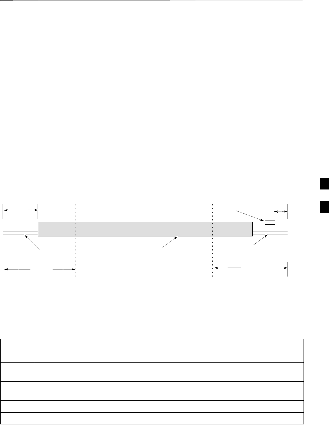
RGPS Cabling for Multiple BTS Sites Equipped with Optional Primary
Surge Suppressor – continued
JAN 2002 5-25
SCt300 1X BTS Hardware Installation, ATP, and FRU Procedures
DRAFT
Surge suppressors
Surge suppressors (Polyphaser 097–1017A–A.1) are required for certain
installations.
Cable Diagrams and
Description
Figure 5-21 shows the RGPS cabling for a multi–BTS configuration for
an RGPS (synchronous) configuration. Figure 5-22 shows the RGPS
cabling for a multi–BTS HSO (non–synchronous) configuration.
Figure 5-17 shows the general construction of the RGPS Sync Cable
(cable X). Cable X is supplied by Motorola with a 7.5 k Ohm, 1W
resistor already installed 150 mm from the end of the cable on the
blue/black wire. There is 200 mm on each end of the cable where the
jacketing has been cut back.
If necessary, the jacketing of cable X may be cut back further for proper
strain relief. For installations that require surge protection, you may cut
cable X at the dashed lines and insert the surge protection devices. Refer
to Table 5-21 for instructions to install the RGPS with surge protection.
Figure 5-17: RGPS Sync Cable Diagram
7.5 K OHM, 1W
RESISTOR
RGPS SYNC CABLE
LOOSE WIRES LOOSE WIRES
CABLE JACKET
200mm
150mm
5M MAX5M MAX 5M MAX5M MAX
Procedure to Install RGPS
Cabling for an Indoor
Installation
Use the procedure in Table 5-20 to connect the RGPS Sync cable for an
indoor installation. Refer to the cable run list in Table 5-23, Figure 5-21,
and Figure 5-22.
Table 5-20: Procedure to Install RGPS Cabling for an Indoor Installation
Step Action
1Connect the resistor end of the RGPS Sync Cable (cable X) to the sync reverse lines on the Site
I/O interface of BTS N. Refer to Figure 5-18. Refer to Table 5-23 for the cable X pinouts .
2Connect the drain wire of cable X to a lug terminal tied directly to the master ground (earth
ground) of BTS N.
3Route cable X from BTS N to BTS N+1.
. . . continued on next page
5

RGPS Cabling for Multiple BTS Sites Equipped with Optional Primary
Surge Suppressor – continued
DRAFT
SCt300 1X BTS Hardware Installation, ATP, and FRU Procedures JAN 2002
5-26
Table 5-20: Procedure to Install RGPS Cabling for an Indoor Installation
Step Action
4Remove excess cable length from cable X and terminate to the sync forward lines on the Site I/O
interface of BTS N+1. Refer to Table 5-23 for the cable X pinouts. Do not terminate the drain
wire to the ground at the Site I/O interface at BTS N+1.
wire to the ground at the Site I/O interface at BTS N+1.
NOTE
If necessary for proper strain relief, the jacketing of cable X may be cut back further.
Figure 5-18: RGPS Sync Cable for Indoor Installation
SITE I/O
INTERFACE SITE I/O
INTERFACE
BTS N
BTS N+1
7.5 K OHM, 1W RESISTOR
ATTACH DRAIN WIRE
TO MASTER GROUND
OF BTS N ONLY
RGPS SYNC CABLE
LOOSE WIRES
LUG TERMINAL
MASTER
GROUND
Procedure to Install RGPS
Cabling for an Outdoor
Installation
Use the procedure in Table 5-21 to install the RGPS cabling for any
installation that may be susceptible to surges or where any portion of the
RGPS cable is routed outside. In these cases, you must reduce the
length of the RGPS cable by (still to be determined length) to
accommodate for the additional timing error incurred by adding surge
protection.
Table 5-21: Procedure to Install RGPS Cabling for an Outdoor Installation
Step Action
1Follow all of the procedures in the “Connect RGPS Cables for Indoor Installation” procedure in
Table 5-20.
2Cut cable X to a maximum distance of 5m from BTS N.
3Install the surge protection device at this point, with the protected side towards BTS N.
4Ground the surge protection device to the master ground of BTS N.
. . . continued on next page
5

RGPS Cabling for Multiple BTS Sites Equipped with Optional Primary
Surge Suppressor – continued
JAN 2002 5-27
SCt300 1X BTS Hardware Installation, ATP, and FRU Procedures
DRAFT
Table 5-21: Procedure to Install RGPS Cabling for an Outdoor Installation
Step Action
5When you cut the cable in step 2, the jacketing for the portion of cable X on the unprotected side
of the surge suppressor is not grounded. To ground this portion of cable X, connect the drain wire
to a lug terminal tied directly to the master ground of BTS N.
NOTE
Only ground the end of the cable jacket at BTS N. Do not ground the jacket at BTS N+1. Refer
to Figure 5-19.
6Cut cable X to a maximum distance of 5m from BTS N+1.
7Ground the surge protection device to the master ground of BTS N+1.
8When you cut cable X in step 6, the jacketing for the portion of cable X between BTS N+1 and
the newly–inserted surge protector is ungrounded. To ground this portion of cable X, connect the
drain wire from one end of the jacket of the cable to a lug terminal tied directly to the master
ground of BTS N+1. Refer to Figure 5-19.
Figure 5-19: RGPS Sync Cable for Outdoor Installations
SITE I/O
INTERFACE
BTS N
BTS N+1
7.5 K OHM, 1W
RESISTOR
Attach the drain wires to the earth grounds. The
length of cable between surge suppressors should
be attached to the earth ground at BTS N only.
RGPS SYNC CABLE SITE I/O
INTERFACE
SURGE
SUPPRESSOR
SURGE
SUPPRESSOR
Ground the surge
suppressors to the
master grounds at each
BTS
5M MAX
MASTER
GROUND
BTS N+1
MASTER
GROUND
BTS N
5M MAX
LUG
TERMINAL
LUG
TERMINAL
Outdoor installation exceptions
In cases where it is impossible or impractical to route cable X in a
continuous stretch from BTS N to BTS N+1, you may cut and rejoin the
cable using an inline splice (solder or crimp). Both types of connections
are acceptable as long as each wire remains electrically isolated from
every other wire. The twisted pairs must be kept together. Refer to
Table 5-22 for the pairing of the twisted pairs.
5

RGPS Cabling for Multiple BTS Sites Equipped with Optional Primary
Surge Suppressor – continued
DRAFT
SCt300 1X BTS Hardware Installation, ATP, and FRU Procedures JAN 2002
5-28
You must splice the drain wire as well. Apply a weatherproof heat
shrink tubing or another weatherproof covering over the cable bundle in
the spliced section. Refer to Figure 5-20.
Figure 5-20: Cutting and Splicing RGPS Sync Cable
Splice each wire including the
drain wire.
Shrink wrap entire spliced area
Table 5-22: Twisted Pairs for RGPS Sync Cable (Cable X)
Pair Color
1Red/Black
Red
2White/Black
White
3Green/Black
Green
4Blue/Black
Blue
5Yellow/Black
Yellow
6Brown/Black
Brown
5

RGPS Cabling for Multiple BTS Sites Equipped with Optional Primary
Surge Suppressor – continued
JAN 2002 5-29
SCt300 1X BTS Hardware Installation, ATP, and FRU Procedures
DRAFT
Cable Connections
For a full signal description of the Site I/O cable, refer to Table 5-14 in
the “Site I/O, Span Line, RGPS and Modem Cabling For Sites Equipped
With Primary Surge Suppressor” procedure.
The pin number and wire color are based on the Site I/O
cable. The pin number corresponds to pins on the Site I/O
junction box connectors.
NOTE
Table 5-23: Multi–BTS RGPS Cable Run List for Primary Surge Suppressor
Sync Reverse – From BTS N Interconnecting
RGPS Cable
(Cable X)
Sync Forward – To BTS N+1
Punchblock
Location Signal RGPS Cable
Color Punchblock
Location Signal
OSP 9T Data to Tail–Green/Black OSP 14T Data from Head–
OSP 9R Data to Tail+ Green OSP 14R Data from Head+
OSP 10T Data from Tail–White/Black OSP 15T Data to Head–
OSP 10R Data from Tail+ White OSP 15R Data to Head+
OSP 11T 1 PPS to Tail–Brown/Black OSP 16T 1 PPS from Head–
OSP 11R 1 PPS to Tail+ Brown OSP 16R 1 PPS from Head+
OSP 12T 1 PPS from Tail–Red/Black OSP 17T 1 PPS to Head–
OSP 12R 1 PPS from Tail+ Red OSP 17R 1 PPS to Head+
OSP 20T Ground* Blue/Black OSP 20R Ground*
*The Multi–BTS Synchronization interface must also be referenced to the BTS digital ground through a 7.5K
ohm, 1W resistor. This resistor has been integrated into the blue/black wire of Cable X. The end of Cable X
with the resistor should be connected to the Sync Reverse locations on the punch block of BTS N. The
opposite end of Cable X is connected to the Sync Forward locations on the punch block of BTS N+1 and may
be cut to the appropriate length.
5
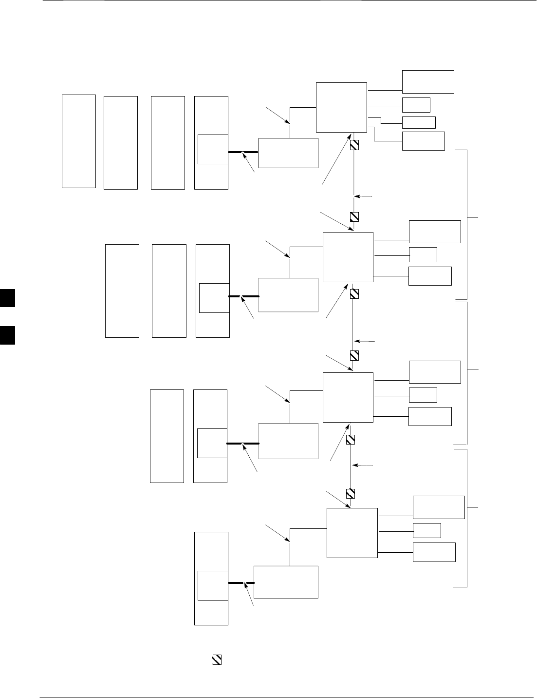
RGPS Cabling for Multiple BTS Sites Equipped with Optional Primary
Surge Suppressor – continued
DRAFT
SCt300 1X BTS Hardware Installation, ATP, and FRU Procedures JAN 2002
5-30
Figure 5-21: Site I/O Interface Cabling for RGPS (Synchronous) Configurations
PRIMARY
SURGE
SUPPRESSOR
SITE I/O
CABLE
SITE I/O
CABLE
SITE I/O
CABLE
SITE I/O
CABLE
RGPS SYNC
CABLE
NOTE 1: EACH BTS MAY CONTAIN
UP TO FOUR SC300 UNITS.
NOTE 2: A MAXIMUM OF 12 BTS MAY
BE INTERCONNECTED WITH A
MAXIMUM DAISY CHAIN CABLE
LENGTH OF 600M BETWEEN EACH
BTS. A MAXIMUM OF SEVEN BTS
MAY BE INTERCONNECTED WITH A
MAXIMUM DAISY CHAIN CABLE
LENGTH OF 1KM BETWEEN EACH
BTS.
MAXIMUM
DISTANCE IS
1 KM (SEE
NOTE 2)
BTS 1
(SEE NOTE 1)
BTS 3
(SEE NOTE 1)
BTS 4
(SEE NOTE 1)
X
X
X
BTS 2
(SEE NOTE 1)
MAXIMUM
DISTANCE IS
1 KM (SEE
NOTE 2)
MAXIMUM
DISTANCE IS
1 KM (SEE
NOTE 2)
UPSTREAM
UPSTREAM
UPSTREAM
DOWNSTREAM
DOWNSTREAM
DOWNSTREAM
PRIMARY
SURGE
SUPPRESSOR
PRIMARY
SURGE
SUPPRESSOR
PRIMARY
SURGE
SUPPRESSOR
CUSTOMER
INPUTS
SPAN
RGPS
PHONE
(MODEM)
M
N
O
V
SITE I/O
INTERFACE
CUSTOMER
INPUTS
SPAN
PHONE
(MODEM)
N
O
V
SITE I/O
INTERFACE
CUSTOMER
INPUTS
SPAN
PHONE
(MODEM)
N
O
V
SITE I/O
INTERFACE
CUSTOMER
INPUTS
SPAN
PHONE
(MODEM)
N
O
V
SITE I/O
INTERFACE
1–IN CONDUIT
(CABLES O, N, V,
AND X)
1–IN CONDUIT
(CABLES O, N, V,
AND X)
1–IN CONDUIT
(CABLES O, N, V,
AND X)
1–IN CONDUIT
(CABLES O, N, M, V
AND X)
= SURGE PROTECTION DEVICE (OPTIONAL)
RGPS SYNC
CABLE
RGPS SYNC
CABLE
UNIT
301 UNIT
201 UNIT
101 UNIT 1
UNIT
201 UNIT
101 UNIT 1
UNIT
101 UNIT 1
UNIT 1
5
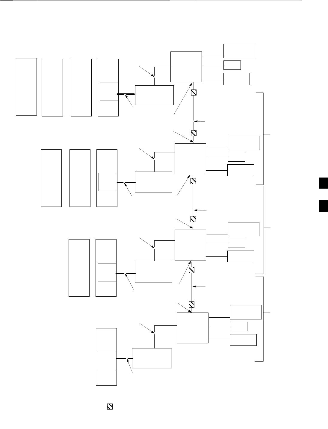
RGPS Cabling for Multiple BTS Sites Equipped with Optional Primary
Surge Suppressor – continued
JAN 2002 5-31
SCt300 1X BTS Hardware Installation, ATP, and FRU Procedures
DRAFT
Figure 5-22: Site I/O Interface Cabling for HSO (Non–Synchronous) Configurations
PRIMARY
SURGE
SUPPRESSOR
SITE I/O
CABLE
SITE I/O
CABLE
SITE I/O
CABLE
SITE I/O
CABLE
NOTE 1: EACH BTS MAY CONTAIN UP
TO FOUR SC300 UNITS.
NOTE 2: A MAXIMUM OF 12 BTS MAY
BE INTERCONNECTED WITH A
MAXIMUM DAISY CHAIN CABLE
LENGTH OF 600M BETWEEN EACH
BTS. A MAXIMUM OF SEVEN BTS MAY
BE INTERCONNECTED WITH A
MAXIMUM DAISY CHAIN CABLE
LENGTH OF 1 KM BETWEEN EACH
BTS.
MAXIMUM
DISTANCE IS
600 M (SEE
NOTE 2)
BTS 1
(SEE NOTE 1)
BTS 3
(SEE NOTE 1)
BTS 4
(SEE NOTE 1)
X
X
X
BTS 2
(SEE NOTE 1)
MAXIMUM
DISTANCE IS
600 M (SEE
NOTE 2)
MAXIMUM
DISTANCE IS
600 M (SEE
NOTE 2)
UPSTREAM
UPSTREAM
UPSTREAM
DOWNSTREAM
DOWNSTREAM
DOWNSTREAM
PRIMARY
SURGE
SUPPRESSOR
PRIMARY
SURGE
SUPPRESSOR
PRIMARY
SURGE
SUPPRESSOR
CUSTOMER
INPUTS
SPAN
PHONE
(MODEM)
N
O
V
SITE I/O
INTERFACE
CUSTOMER
INPUTS
SPAN
PHONE
(MODEM)
N
O
V
SITE I/O
INTERFACE
CUSTOMER
INPUTS
SPAN
PHONE
(MODEM)
N
O
V
SITE I/O
INTERFACE
CUSTOMER
INPUTS
SPAN
PHONE
(MODEM)
N
O
V
SITE I/O
INTERFACE
1–IN CONDUIT
(CABLES O, N, V,
AND X)
1–IN CONDUIT
(CABLES O, N, V,
AND X)
1–IN CONDUIT
(CABLES O, N, V,
AND X)
1–IN CONDUIT
(CABLES O, N, V,
AND X)
= SURGE PROTECTION DEVICE (OPTIONAL)
RGPS SYNC
CABLE
RGPS SYNC
CABLE
RGPS SYNC
CABLE
UNIT
301 UNIT
201 UNIT
101 UNIT 1
UNIT
201 UNIT
101 UNIT 1
UNIT
101 UNIT 1
UNIT 1
5

Span Line Daisy Chain Cabling for Multiple BTS Sites Equipped with
Optional Primary Surge Suppressor
DRAFT
SCt300 1X BTS Hardware Installation, ATP, and FRU Procedures JAN 2002
5-32
Objective
The objective of this procedure is to install span line cabling between
multiple BTS sites equipped with Primary Surge Suppressor in an open
daisy chain configuration.
Background
This feature allows multiple BTS sites to be linked together in an open
daisy chain loop using a single T1/E1 span. This will reduce the number
of spans necessary to support a CDMA system and minimize unused
channels.
Each BTS site may contain up to four units. A maximum of 12 BTS
sites may be combined in a single daisy chain.
Required Cables
The following cables are necessary to do this procedure.
Table 5-24: Required Cables for Span Line Daisy Chain Cabling
Cable Qty. Part Number Description
W 1–3 Customer
Supplied Span Line Daisy Chain Cable
Procedure
Attach the span line daisy chain cable (Cable W) to the site I/O interface
of each BTS site. Refer to Figure 5-23 and Table 5-25.
Cable Connections
Table 5-25 shows the cable run information for span line daisy chain
cabling for BTS sites equipped with the Primary Surge Suppressor.
For a full signal description of the Site I/O cable refer to Table 5-14 in
the “Site I/O, Span Line, RGPS and Modem Cabling for Sites Equipped
with Optional Primary Surge Suppressor” procedure.
The pin number and wire color are based on the Site I/O
cable. The pin number corresponds to pins on the Site I/O
junction box connectors.
NOTE
5

Span Line Daisy Chain Cabling for Multiple BTS Sites Equipped with
Optional Primary Surge Suppressor – continued
JAN 2002 5-33
SCt300 1X BTS Hardware Installation, ATP, and FRU Procedures
DRAFT
Table 5-25: Cable Run List for Span Line Daisy Chain Cabling
BTS 1 (Secondary Backhaul –
Span B Downstream) BTS 2 (Primary Backhaul –
Span A Upstream)
Punchdown
Block Location Desc. Punchdown
Block Location Desc.
OSP 23T RX TIP OSP 22T TX TIP
OSP 23R RX RING OSP 22R TX RING
OSP 24T TX TIP OSP 21T RX TIP
OSP 24R TX RING OSP 21R RX RING
5
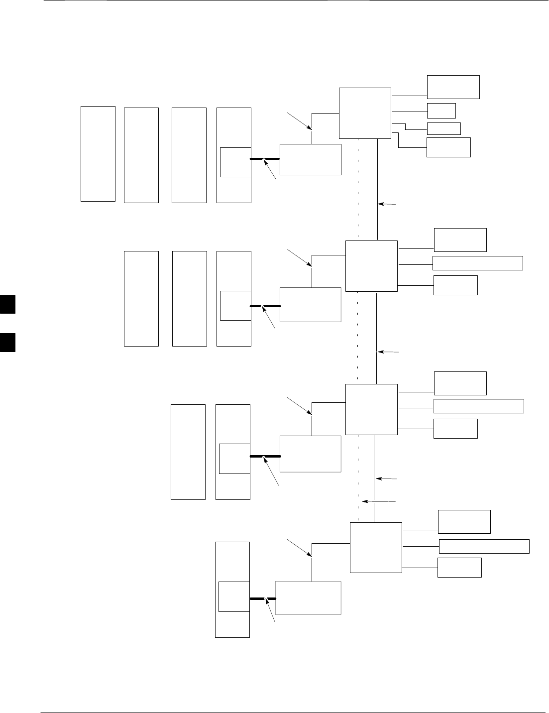
Span Line Daisy Chain Cabling for Multiple BTS Sites Equipped with
Optional Primary Surge Suppressor – continued
DRAFT
SCt300 1X BTS Hardware Installation, ATP, and FRU Procedures JAN 2002
5-34
Figure 5-23: Site I/O Interface Cabling for Span Line Daisy Chain Cabling
PRIMARY
SURGE
SUPPRESSOR
SITE I/O
CABLE
SITE I/O
CABLE
SITE I/O
CABLE
SITE I/O
CABLE
SPAN LINE DAISY
CHAIN CABLE
SPAN LINE DAISY
CHAIN CABLE
SPAN LINE DAISY
CHAIN CABLE
NOTE 1: EACH BTS SITE MAY
CONSIST OF UP TO FOUR SC300
UNITS. THERE MAY BE A TOTAL OF
12 BTS IN A DAISY CHAIN.
NOTE 2: THE USE OF AN RGPS IS
DEPENDANT UPON WHETHER OR
NOT THE SITES USE A MULTI–BTS
SITE RGPS CONFIGURATION.
NOTE 3: THE USE OF THE
MULTI–BTS RGPS CABLE (CABLE X)
DEPENDS UPON SYSTEM
CONFIGURATION.
BTS 1
(SEE NOTE 1)
BTS 3
(SEE NOTE 1)
BTS 4
(SEE NOTE 1)
W
W
W
BTS 2
(SEE NOTE 1)
PRIMARY
SURGE
SUPPRESSOR
PRIMARY
SURGE
SUPPRESSOR
PRIMARY
SURGE
SUPPRESSOR
CUSTOMER
INPUTS
SPAN
RGPS
PHONE
(MODEM)
M
N
O
V
SITE I/O
INTERFACE
CUSTOMER
INPUTS
RGPS (SEE NOTE 2)
PHONE
(MODEM)
M
O
V
SITE I/O
INTERFACE
CUSTOMER
INPUTS
PHONE
(MODEM)
M
O
V
SITE I/O
INTERFACE
CUSTOMER
INPUTS
PHONE
(MODEM)
M
O
V
SITE I/O
INTERFACE
1–IN CONDUIT
(CABLES O, M, V,
W, AND X)
(SEE NOTE 3)
1–IN CONDUIT
(CABLES O, M, V,
W, AND X)
(SEE NOTE 3)
1–IN CONDUIT
(CABLES O, M, V,
W AND X)
(SEE NOTE 3)
1–IN CONDUIT
(CABLES O, N, M,
V, W, AND X)
(SEE NOTE 3)
RGPS (SEE NOTE 2)
RGPS (SEE NOTE 2)
X/1
(SEE NOTE 3)
X/1
(SEE NOTE 3)
X/1
(SEE NOTE 3)
UNIT
301 UNIT
201 UNIT
101 UNIT 1
UNIT
201 UNIT
101 UNIT 1
UNIT
101 UNIT 1
UNIT 1
5

JAN 2002 SCt300 1X BTS Hardware Installation, ATP, and FRU Procedures
DRAFT
Chapter 6: Installing the Unit and Installation Check Off List
Table of Contents
Unit Installation Overview 6-1. . . . . . . . . . . . . . . . . . . . . . . . . . . . . . . . . . . . . . . . .
Overview 6-1. . . . . . . . . . . . . . . . . . . . . . . . . . . . . . . . . . . . . . . . . . . . . . . .
Unit Installation Procedure Order 6-1. . . . . . . . . . . . . . . . . . . . . . . . . . . . .
Connector Locations 6-2. . . . . . . . . . . . . . . . . . . . . . . . . . . . . . . . . . . . . . . . . . . . . .
Connector Locations for MicroCell and Primary Surge Suppressor 6-2. . .
Attaching Back Fin Cover to Unit 6-4. . . . . . . . . . . . . . . . . . . . . . . . . . . . . . . . . . .
Objective 6-4. . . . . . . . . . . . . . . . . . . . . . . . . . . . . . . . . . . . . . . . . . . . . . . .
When to Use the Fin Covers 6-4. . . . . . . . . . . . . . . . . . . . . . . . . . . . . . . . .
Procedure to Install Back Fin Cover to Unit 6-4. . . . . . . . . . . . . . . . . . . . .
Attaching Optional Installation Handles to the Unit 6-5. . . . . . . . . . . . . . . . . . . . .
Objective 6-5. . . . . . . . . . . . . . . . . . . . . . . . . . . . . . . . . . . . . . . . . . . . . . . .
Required Tools and Materials 6-5. . . . . . . . . . . . . . . . . . . . . . . . . . . . . . . .
Procedure to Attach the Installation Handles to the Unit 6-5. . . . . . . . . . .
Attaching Unit to Mounting Bracket 6-7. . . . . . . . . . . . . . . . . . . . . . . . . . . . . . . . .
Objective 6-7. . . . . . . . . . . . . . . . . . . . . . . . . . . . . . . . . . . . . . . . . . . . . . . .
Background 6-7. . . . . . . . . . . . . . . . . . . . . . . . . . . . . . . . . . . . . . . . . . . . . .
Required Tools and Equipment 6-7. . . . . . . . . . . . . . . . . . . . . . . . . . . . . . .
Procedure to Attach the Unit to the Mounting Bracket 6-7. . . . . . . . . . . . .
Earth Ground Cabling 6-9. . . . . . . . . . . . . . . . . . . . . . . . . . . . . . . . . . . . . . . . . . . . .
Objective 6-9. . . . . . . . . . . . . . . . . . . . . . . . . . . . . . . . . . . . . . . . . . . . . . . .
Other Grounding Considerations 6-9. . . . . . . . . . . . . . . . . . . . . . . . . . . . . .
Required Cables 6-9. . . . . . . . . . . . . . . . . . . . . . . . . . . . . . . . . . . . . . . . . . .
Required Tools and Materials 6-9. . . . . . . . . . . . . . . . . . . . . . . . . . . . . . . .
Procedure to Attach the Earth Ground Cables 6-9. . . . . . . . . . . . . . . . . . . .
Attaching Front Fin Cover to Unit 6-11. . . . . . . . . . . . . . . . . . . . . . . . . . . . . . . . . . .
Objective 6-11. . . . . . . . . . . . . . . . . . . . . . . . . . . . . . . . . . . . . . . . . . . . . . . .
When to Use the Fin Covers 6-11. . . . . . . . . . . . . . . . . . . . . . . . . . . . . . . . .
Procedure to Attach the Front Fin Cover to Unit 6-11. . . . . . . . . . . . . . . . .
Attaching the Site I/O Junction Box to the Unit 6-12. . . . . . . . . . . . . . . . . . . . . . . .
Objective 6-12. . . . . . . . . . . . . . . . . . . . . . . . . . . . . . . . . . . . . . . . . . . . . . . .
Required Tools and Materials 6-12. . . . . . . . . . . . . . . . . . . . . . . . . . . . . . . .
Procedure to Attach the Site I/O Junction Box to the Unit 6-12. . . . . . . . . .
Procedure to Attach a Site I/O Cap to the Unit (optional) 6-13. . . . . . . . . .
6

Table of Contents – continued
DRAFT
SCt300 1X BTS Hardware Installation, ATP, and FRU Procedures JAN 2002
Attaching the Short Duration Battery to the Unit (optional) 6-14. . . . . . . . . . . . . . .
Objective 6-14. . . . . . . . . . . . . . . . . . . . . . . . . . . . . . . . . . . . . . . . . . . . . . . .
Required Tools and Materials 6-14. . . . . . . . . . . . . . . . . . . . . . . . . . . . . . . .
Procedure to Attach the Short Duration Battery to the Unit 6-14. . . . . . . . .
Short Duration Battery Cabling 6-16. . . . . . . . . . . . . . . . . . . . . . . . . . . . . . . . . . . . .
Objective 6-16. . . . . . . . . . . . . . . . . . . . . . . . . . . . . . . . . . . . . . . . . . . . . . . .
Battery Cable 6-16. . . . . . . . . . . . . . . . . . . . . . . . . . . . . . . . . . . . . . . . . . . . .
Procedure to Install Short Duration Battery Cable to the Unit 6-16. . . . . . .
AC Power Cabling 6-18. . . . . . . . . . . . . . . . . . . . . . . . . . . . . . . . . . . . . . . . . . . . . . .
Objective 6-18. . . . . . . . . . . . . . . . . . . . . . . . . . . . . . . . . . . . . . . . . . . . . . . .
Required Cables 6-18. . . . . . . . . . . . . . . . . . . . . . . . . . . . . . . . . . . . . . . . . . .
Power Cable and Connector Signal Information 6-18. . . . . . . . . . . . . . . . . .
Procedure to Connect AC Input Power Cable to the Unit 6-18. . . . . . . . . . .
DC Power Cabling 6-20. . . . . . . . . . . . . . . . . . . . . . . . . . . . . . . . . . . . . . . . . . . . . . .
Objective 6-20. . . . . . . . . . . . . . . . . . . . . . . . . . . . . . . . . . . . . . . . . . . . . . . .
Required Cables 6-20. . . . . . . . . . . . . . . . . . . . . . . . . . . . . . . . . . . . . . . . . . .
Power Cable and Connector Signal Information 6-20. . . . . . . . . . . . . . . . . .
Procedure to Connect DC Input Power Cabling to the Unit 6-20. . . . . . . . .
Antenna Cabling for Sites Equipped with
Customer–Supplied Site I/O Interface 6-22. . . . . . . . . . . . . . . . . . . . . . . . . . . . . . . .
Objective 6-22. . . . . . . . . . . . . . . . . . . . . . . . . . . . . . . . . . . . . . . . . . . . . . . .
Required Cables 6-22. . . . . . . . . . . . . . . . . . . . . . . . . . . . . . . . . . . . . . . . . . .
Procedure to Install Antenna Cabling 6-22. . . . . . . . . . . . . . . . . . . . . . . . . .
Antenna Cabling for Sites Equipped with Optional Primary Surge Suppressor 6-25
Objective 6-25. . . . . . . . . . . . . . . . . . . . . . . . . . . . . . . . . . . . . . . . . . . . . . . .
Cable Labels 6-25. . . . . . . . . . . . . . . . . . . . . . . . . . . . . . . . . . . . . . . . . . . . .
Required Cables 6-25. . . . . . . . . . . . . . . . . . . . . . . . . . . . . . . . . . . . . . . . . . .
Procedure to Install Antenna Lightning Arrestors and Antenna Cabling 6-25
MIB Cabling for Multi–Unit Logical BTS Configurations 6-30. . . . . . . . . . . . . . . .
Overview 6-30. . . . . . . . . . . . . . . . . . . . . . . . . . . . . . . . . . . . . . . . . . . . . . . .
Cable Labels 6-30. . . . . . . . . . . . . . . . . . . . . . . . . . . . . . . . . . . . . . . . . . . . .
Required Tools and Equipment 6-30. . . . . . . . . . . . . . . . . . . . . . . . . . . . . . .
Procedure to Install MIB Cabling 6-32. . . . . . . . . . . . . . . . . . . . . . . . . . . . .
Subscriber Unit (SU) Cabling 6-34. . . . . . . . . . . . . . . . . . . . . . . . . . . . . . . . . . . . . . .
Objective 6-34. . . . . . . . . . . . . . . . . . . . . . . . . . . . . . . . . . . . . . . . . . . . . . . .
Required Tools and Equipment 6-34. . . . . . . . . . . . . . . . . . . . . . . . . . . . . . .
Procedure to Install SU Cabling 6-34. . . . . . . . . . . . . . . . . . . . . . . . . . . . . .
Terminating Unused Connections 6-36. . . . . . . . . . . . . . . . . . . . . . . . . . . . . . . . . . . .
Objective 6-36. . . . . . . . . . . . . . . . . . . . . . . . . . . . . . . . . . . . . . . . . . . . . . . .
List of Terminators for Unused Connections 6-36. . . . . . . . . . . . . . . . . . . . .
Procedure 6-36. . . . . . . . . . . . . . . . . . . . . . . . . . . . . . . . . . . . . . . . . . . . . . . .
Powering on the Unit and Mounting the Solar Cover 6-37. . . . . . . . . . . . . . . . . . . .
Objective 6-37. . . . . . . . . . . . . . . . . . . . . . . . . . . . . . . . . . . . . . . . . . . . . . . .
You May Want to Wait 6-37. . . . . . . . . . . . . . . . . . . . . . . . . . . . . . . . . . . . . .
Required Tools and Materials 6-37. . . . . . . . . . . . . . . . . . . . . . . . . . . . . . . .
6

Table of Contents – continued
JAN 2002 SCt300 1X BTS Hardware Installation, ATP, and FRU Procedures
DRAFT
Procedure to Power On the Unit and Mount Solar Cover 6-37. . . . . . . . . . .
Procedure to Power On the Surge Suppressor, the Unit, and
Mount the Solar Cover 6-37. . . . . . . . . . . . . . . . . . . . . . . . . . . . . . . . . . . . .
Site Cleanup 6-40. . . . . . . . . . . . . . . . . . . . . . . . . . . . . . . . . . . . . . . . . . . . . . . . . . . .
Remove Protective Covering 6-40. . . . . . . . . . . . . . . . . . . . . . . . . . . . . . . . .
Lighting Fixtures 6-40. . . . . . . . . . . . . . . . . . . . . . . . . . . . . . . . . . . . . . . . . .
Tools 6-40. . . . . . . . . . . . . . . . . . . . . . . . . . . . . . . . . . . . . . . . . . . . . . . . . . .
Materials 6-40. . . . . . . . . . . . . . . . . . . . . . . . . . . . . . . . . . . . . . . . . . . . . . . .
Remove Debris 6-40. . . . . . . . . . . . . . . . . . . . . . . . . . . . . . . . . . . . . . . . . . .
Environment 6-40. . . . . . . . . . . . . . . . . . . . . . . . . . . . . . . . . . . . . . . . . . . . .
Installation Completion Checklist 6-41. . . . . . . . . . . . . . . . . . . . . . . . . . . . . . . . . . .
Directions 6-41. . . . . . . . . . . . . . . . . . . . . . . . . . . . . . . . . . . . . . . . . . . . . . . .
Installation Completion Checklist 6-41. . . . . . . . . . . . . . . . . . . . . . . . . . . . .
6

Table of Contents – continued
DRAFT
SCt300 1X BTS Hardware Installation, ATP, and FRU Procedures JAN 2002
Notes
6

Unit Installation Overview
JAN 2002 6-1
SCt300 1X BTS Hardware Installation, ATP, and FRU Procedures
DRAFT
Overview
This chapter provides the procedures for unit installation and cabling.
The site cabling has been installed and routed to the location of the BTS.
In this chapter, the cables will be attached to the unit(s). Cabling
installation will be repeated as necessary for each unit at the BTS.
This chapter provides the information and procedures to:
SAttach the unit to the mounting bracket
SAttach cables to the unit
SPower on the unit
SMount the solar covers
SComplete the installation completion checklist
Unit Installation Procedure
Order
The process of installing the unit requires that the following procedures
be completed in the order shown:
1. Install back fin cover to unit (required for indoor applications if solar
covers will not be used).
2. Attaching the installation handles to the unit (optional).
3. Attaching the unit to the mounting bracket.
4. Remove the installation handles (optional).
5. Attach earth ground cable and optional master ground cable.
6. Attach the Site I/O junction box to the unit.
7. Attach Subscriber Unit (SU) to unit.
8. Attach front fin cover (required for indoor applications if solar
covers will not be used).
9. Attach the short duration battery (optional).
10. Attach the AC input power or DC input power cable.
11. Attach antenna cable(s).
12. Attach the MIB cables (optional).
13. Attach the SU cables (optional).
14. Terminating unused connectors.
15. Powering on the unit.
16. Attach front solar cover (required for outdoor installations and
optional for indoor applications if fin covers will not be used).
17. Cleaning up site.
18. Filling out the installation completion checklist.
6
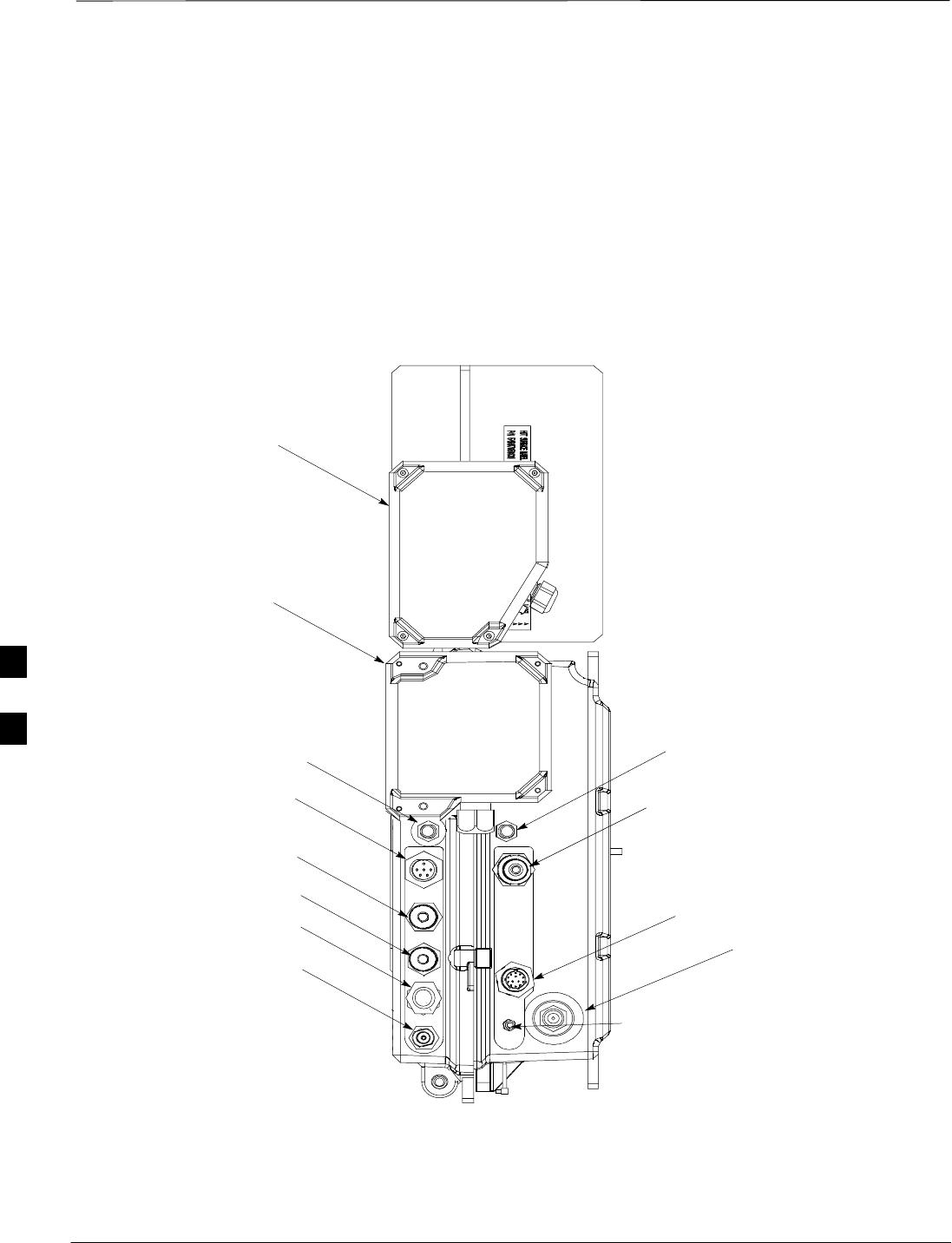
Connector Locations
DRAFT
SCt300 1X BTS Hardware Installation, ATP, and FRU Procedures JAN 2002
6-2
Connector Locations for
MicroCell and Primary Surge
Suppressor
Figure 6-1 though Figure 6-3 show the location of the cable connectors
on the Microcell and Primary Surge Suppressor. The system
configuration determines which connectors are used.
Figure 6-1: General Block Diagram Showing the Port Names
SITE I/O
JUNCTION BOX
DC POWER
BREAKER
DC INPUT
MIB C
MIB B
MIB A
ANTENNA A
AC POWER
BREAKER
AC INPUT
SU RF
SU DIGITAL
ANTENNA B
SUBSCRIBER UNIT
NOTE: CABLES REMOVED FOR
ILLUSTRATION PURPOSES
6
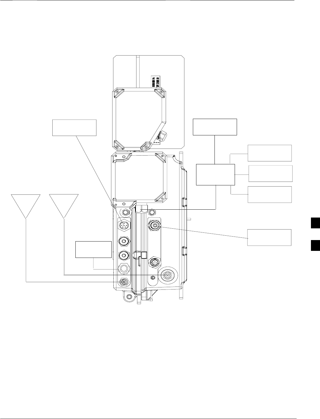
Connector Locations – continued
JAN 2002 6-3
SCt300 1X BTS Hardware Installation, ATP, and FRU Procedures
DRAFT
Figure 6-2: General Block Diagram Showing the Unit, Site I/O Interface, and External Items
ANT
TX/RX
CUSTOMER
INPUTS
SPAN
RGPS
DC
POWER
PHONE
(MODEM)
AC
POWER
SITE I/O
INTERFACE
MIB
TERMINATOR
ANT RX
NOTE: CABLES REMOVED FOR
ILLUSTRATION PURPOSES
6
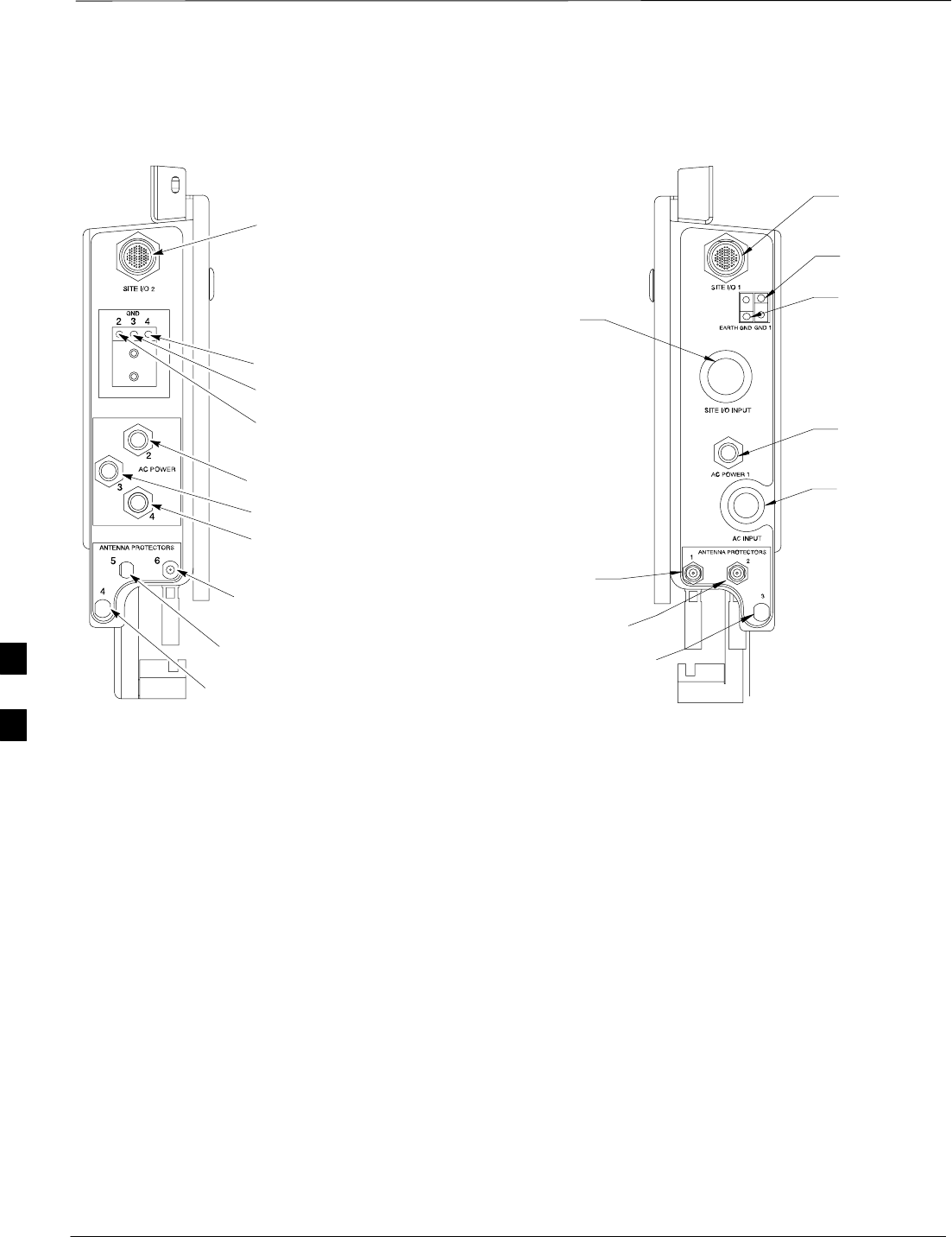
Connector Locations – continued
DRAFT
SCt300 1X BTS Hardware Installation, ATP, and FRU Procedures JAN 2002
6-4
Figure 6-3: Location of Primary Surge Suppressor Connectors
SITE I/O 2
AC POWER 2
AC POWER 3
AC POWER 4
AC POWER 1
AC INPUT
(Conduit Hole)
SITE I/O INPUT
(Conduit Hole)
SITE I/O 1
ANTENNA PROTECTOR 2
ANTENNA PROTECTOR 1
LEFT SIDE RIGHT SIDE
GROUND 4
GROUND 3
GROUND 2
GROUND 1
EARTH
GROUND
ANTENNA PROTECTOR 3
(FOR FUTURE EXPANSION)
ANTENNA PROTECTOR 6
(FOR FUTURE EXPANSION)
ANTENNA PROTECTOR 5
(FOR FUTURE EXPANSION)
ANTENNA PROTECTOR 4
(FOR FUTURE EXPANSION)
6
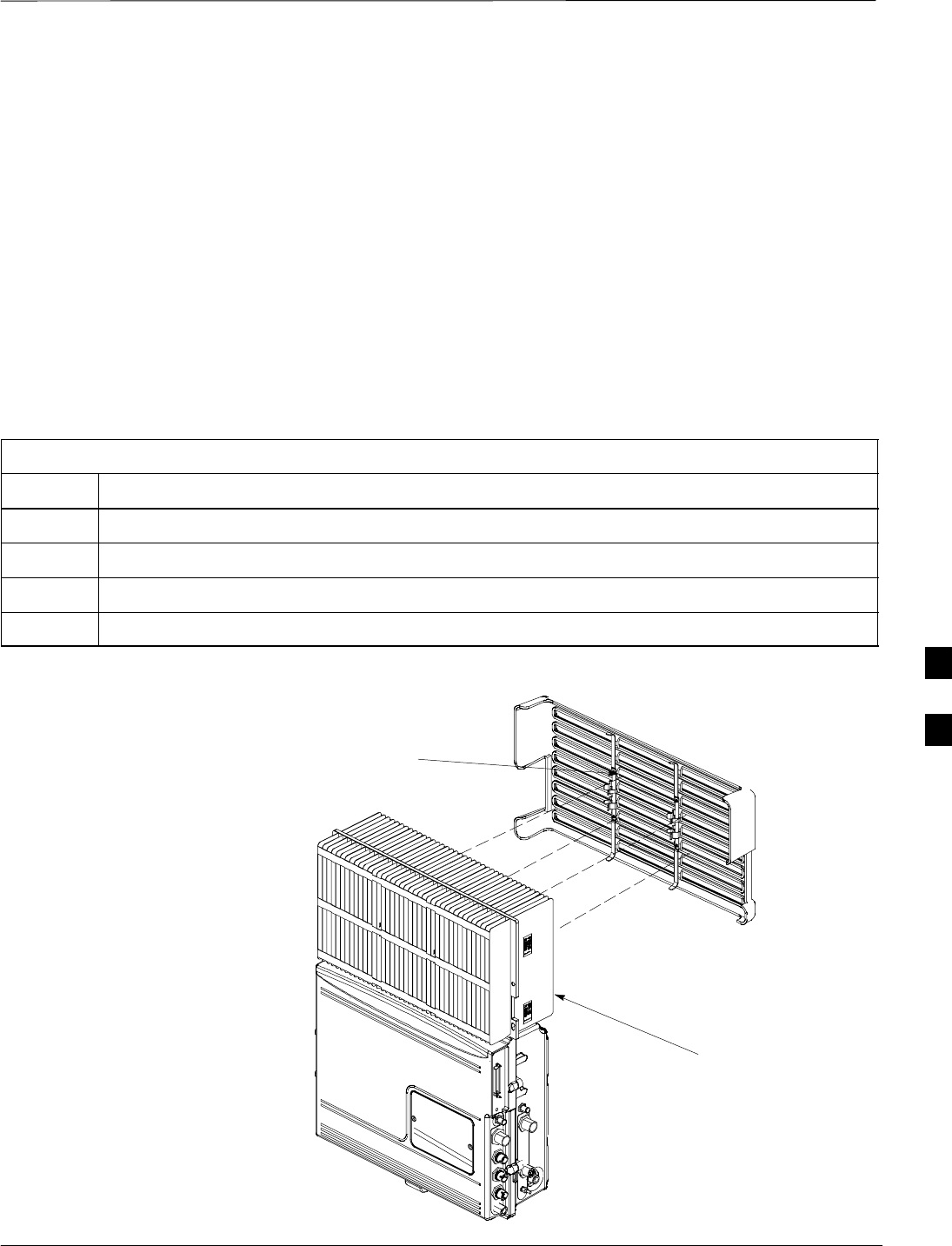
Attaching Back Fin Cover to Unit
JAN 2002 6-5
SCt300 1X BTS Hardware Installation, ATP, and FRU Procedures
DRAFT
Objective
The objective of this procedure is to attach the back fin cover to the
MicroCell unit. The front fin cover is mounted to the unit after the unit
is mounted to the mounting bracket.
When to Use the Fin Covers
You must always use fin covers in an indoor application.
Procedure to Install Back Fin
Cover to Unit
Attach the back fin cover to the unit by following the procedures in
Table 6-1 and the information in Figure 6-4.
Table 6-1: Procedure to Install Back Fin Cover to Unit
Step Action
1Install back fin cover prior to placing unit on the mounting bracket.
2Center fin cover on the fins of the unit. See Figure 6-4 for snap locations.
3Align snap with center tab on fins.
4Push fin cover into place.
Figure 6-4: Attaching Back Fin Cover to Unit
LOCATION OF SNAPS TO ATTACH
FIN COVER TO UNIT
MICROCELL FINS
6
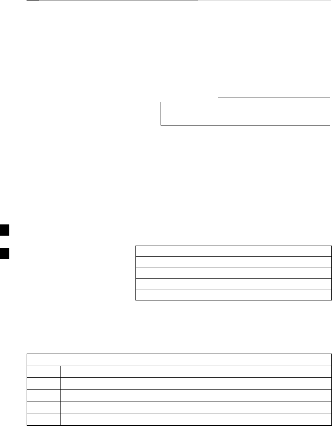
Attaching Optional Installation Handles to the Unit
DRAFT
SCt300 1X BTS Hardware Installation, ATP, and FRU Procedures JAN 2002
6-6
Objective
The objective of this procedure is to attach the installation handles to the
unit. The location for the handles is shown in Figure 6-5. The handles
should be used when lifting or carrying the unit.
Installation handles are available with installation kit
#SGLN5754
NOTE
Required Tools and Materials
Tools
Attaching the installation handles to the unit requires:
ST30 Torx tamper bit
STorque driver wrench, 1/4–in. hex female drive, 0–10 N–M
Motorola parts
Table 6-2 lists the parts necessary to do this procedure.
Table 6-2: Installation Handle Kit
Quantity Part Number Description
2 0387541C08 Screws M6x25
2 0387541C09 Screws M6x35
2 5588425C01 Handle
Procedure to Attach the
Handles to the Unit
Attach the installation handles to the unit by following the procedures in
Table 6-3 and the information in Figure 6-5.
Table 6-3: Procedure to Attach the Installation Handles
Step Action
1Hold one handle in position and start the upper screw. See Figure 6-5.
2Start the lower screw.
3Use a T30 Torx tamper bit to torque the two M6 screws to 5.0 N–m.
4Repeat steps 1–3 for the other handle.
6
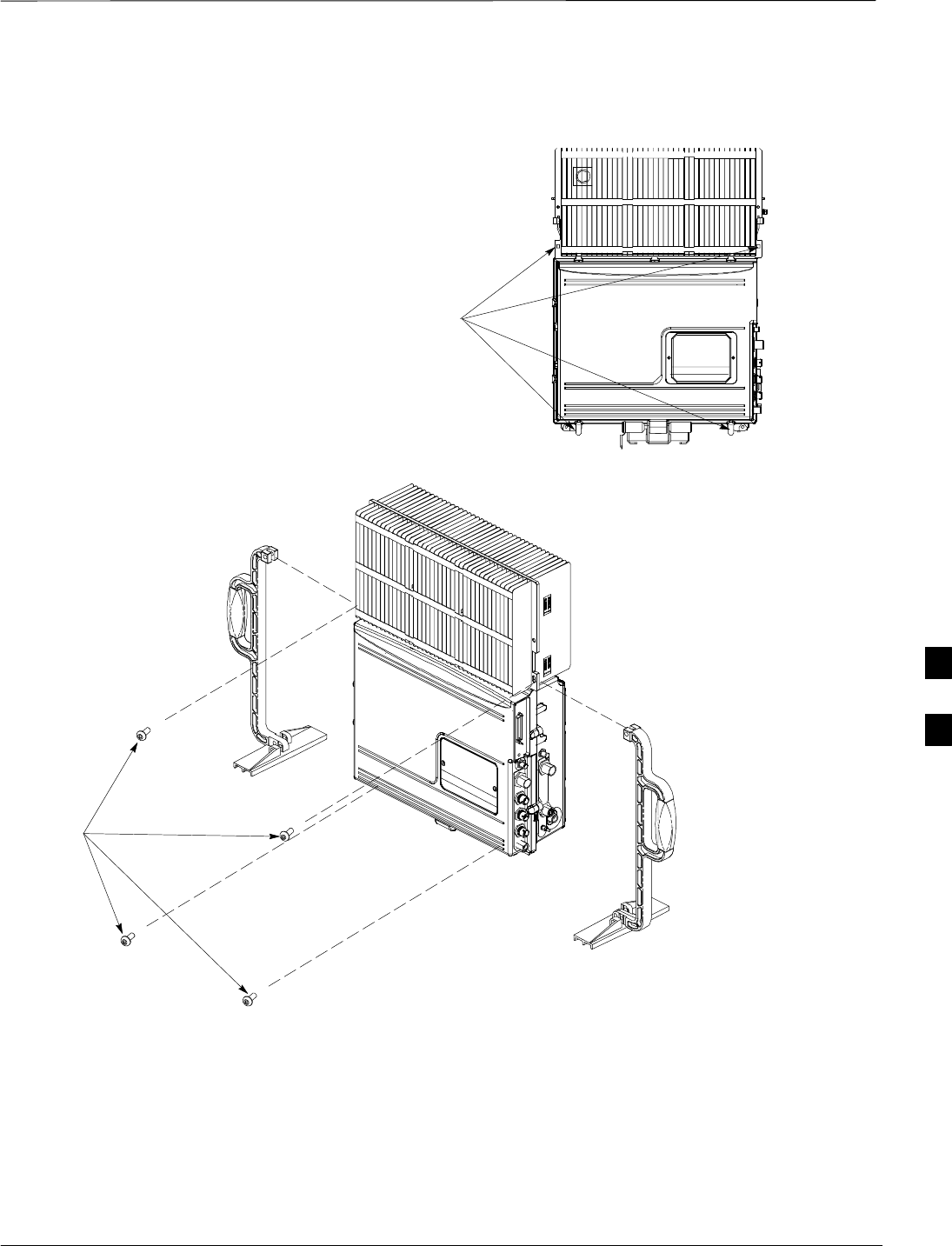
Attaching Installation Handles to the Unit – continued
JAN 2002 6-7
SCt300 1X BTS Hardware Installation, ATP, and FRU Procedures
DRAFT
Figure 6-5: Attaching the Installation Handles to the Unit
M6X19 (4)
INSTALLATION
HANDLE
HOLES USED FOR
MOUNTING HANDLES
INSTALLATION
HANDLE
6
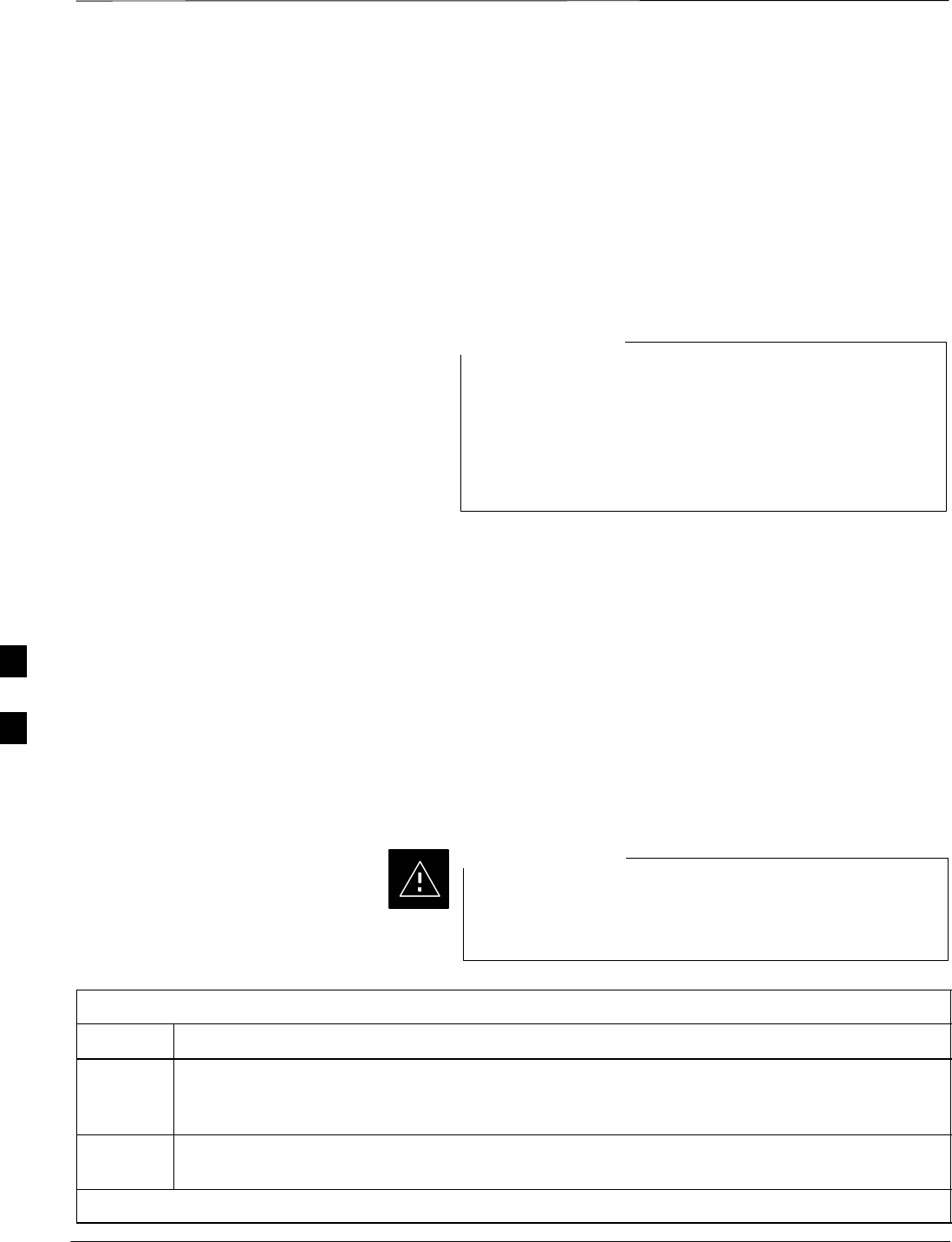
Attaching Unit to Mounting Bracket
DRAFT
SCt300 1X BTS Hardware Installation, ATP, and FRU Procedures JAN 2002
6-8
Objective
The objective of this procedure is to attach the unit to the mounting
bracket. This procedure applies to mounting brackets that are attached to
a rack, wall, or pole.
Background
The unit attaches to the mounting bracket with two (2) M6 screws and
the provided pin or a customer–supplied padlock.
The handles should be mounted to the unit before
mounting the unit to the bracket. The handles should be
used to lift the unit onto the bracket. If the solar cover is to
be used, the back cover must be attached prior to mounting
the unit. Remove the handles once the unit has been
secured to the mounting bracket.
NOTE
Required Tools and Equipment
The following tools and equipment are required to attach the unit to the
mounting bracket:
STorque driver wrench, 1/4–in. hex female drive, 0–10 N–M
ST30 Torx tamper bit
STwo M6X19 screws (Motorola Part Number 0387541C03)
Procedure to Attach the Unit to
the Mounting Bracket
Follow the procedure in Table 6-4 to attach the unit to the mounting
bracket. Refer to Figure 6-6.
Use caution when resting the MicroCell unit on the hooks
of the mounting bracket. Do not leave unit supported by
hooks only.
CAUTION
Table 6-4: Procedure to Attach the Unit to the Mounting Bracket
Step Action
1Lift the unit using the installation handles and place it on the mounting bracket by aligning the
bracket’s upper arms into the rectangular cutouts in the heatsink. The unit will need to be raised
up slightly so that the lower bracket flange does not contact the unit’s lower surface.
2Use a T30 Torx tamper bit to start, but not tighten, both screws in the location shown in
Figure 6-6.
. . . continued on next page
6
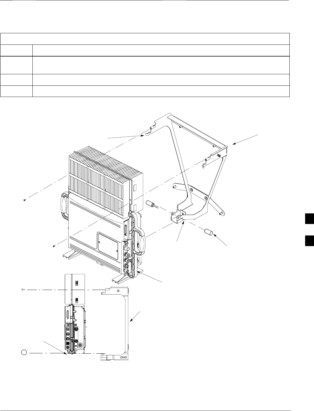
Attaching Unit to Mounting Bracket – continued
JAN 2002 6-9
SCt300 1X BTS Hardware Installation, ATP, and FRU Procedures
DRAFT
Table 6-4: Procedure to Attach the Unit to the Mounting Bracket
Step Action
3At the bottom of the unit, align the hole in the mounting bracket with the hole in the unit. Place
the pin or customer–supplied padlock through this hole. Screw pin together and tighten firmly.
4Use a T30 Torx tamper bit to torque the two mounting screws to 5.0 N–M.
5Use a T30 Torx tamper bit to remove the installation handles.
Figure 6-6: Attaching Unit to V–Style Mounting Bracket
ATTACH THE HANDLES TO
THE UNIT BEFORE LIFTING
HOOKS
MOUNTING
BRACKET
SLIDE PIN THROUGH
HOLES IN BRACKET AND
SCREW TOGETHER
M6 SCREWS (2)
LOCKING INTERFACE
MOUNTING BRACKET
PIN (P/N 5587660C01 OR,
5587660C02)
6

Earth Ground Cabling
DRAFT
SCt300 1X BTS Hardware Installation, ATP, and FRU Procedures JAN 2002
6-10
Objective
The objective of this procedure is to attach the earth ground cabling to
one or more MicroCell units. This procedure covers just the grounding
cables that attach to the MicroCell.
Other Grounding
Considerations
Grounding considerations beyond the ground cables that attach to the
MicroCell are summarized in Appendix A. Refer to Appendix A and the
site documentation for other grounding considerations.
If your site is equipped with the optional Primary Surge Suppressor,
refer to the “Power, Earth Ground, and Battery Cabling” Procedure in
chapter 4 for information about installing the Master Ground cable.
Required Cables
The following cables in Table 6-5 are necessary to do this procedure.
Table 6-5: Required Cables for Earth Ground Cabling
Cable Qty. Part Number Description
A 1–4 3087701C02 Ground cable, 8 -AWG, insulated copper wire. Requires one ring lug
connector. Used for Primary Surge Suppressor Installation.
B 1–4 3087701C01 Ground cable, Site I/O Junction Box to Bracket (for installations
without external Subscriber Unit).
L 1–4 3087701C04 Y–Ground Cable (for external SU and Site I/O).
Y 1 Customer
Supplied Master Ground Cable, 6 -AWG, insulated copper wire. Used for both
Primary Surge Suppressor and non–Primary Surge Suppressor
installations.
Required Tools and Materials
The following tools are required to attach ground cabling to the
MicroCell unit.
S13 mm torque wrench set to 5.0 N–M
SFlathead screwdriver bit
ST30 TORX bit
Procedure to Attach the Earth
Ground Cables
Use the following procedure to attach the ground cables. Refer to
Table 6-6 and Figure 6-7.
Table 6-6: Procedure to Attach the Earth Ground Cables
Step Action
1Remove the hex nuts and lock washers from the ground stud on the mounting bracket. Refer to
Figure 6-8.
. . . continued on next page
6
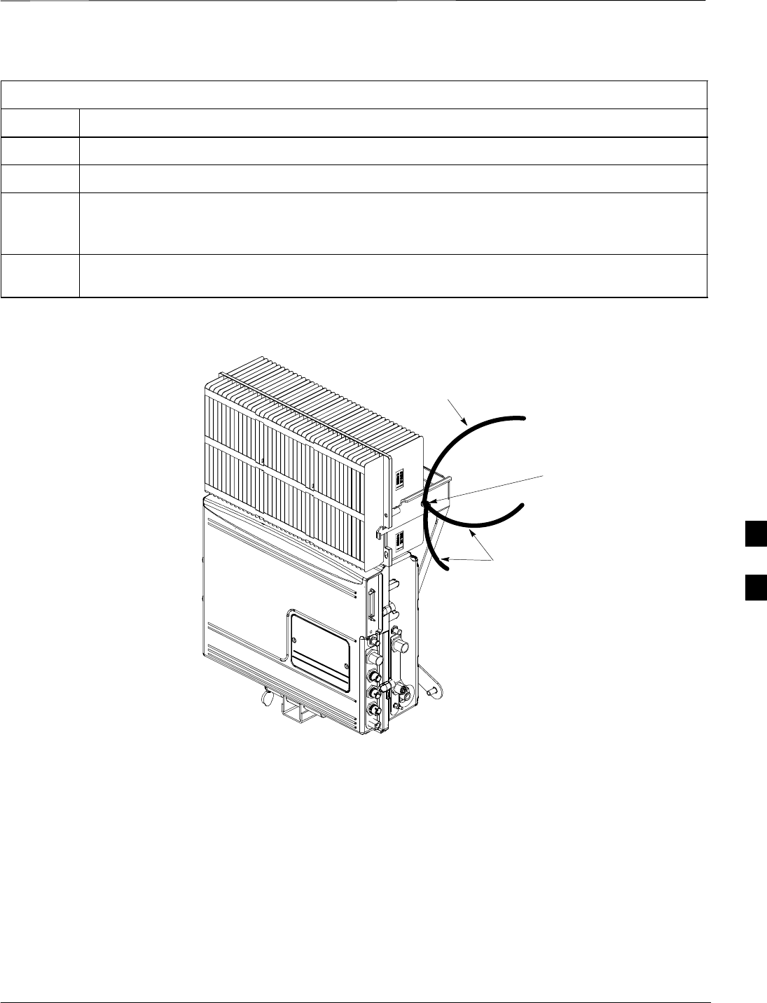
Earth Ground Cabling – continued
JAN 2002 6-11
SCt300 1X BTS Hardware Installation, ATP, and FRU Procedures
DRAFT
Table 6-6: Procedure to Attach the Earth Ground Cables
Step Action
2Attach the master ground cable (cable A or cable Y) to the ground stud on the mounting bracket.
3Replace one lock washer and nut on the ground stud and tighten to 5 N–m.
4Attach the single end of the Y–ground cable (cable L) to the ground stud on the mounting bracket.
If the unit is not equipped with a Site I/O, attach one end of the Site I/O ground cable (cable B) to
the ground stud on the mounting bracket.
5Replace the second lockwasher and hex nut to the ground stud on the mounting bracket. Use a
torque wrench and a 13mm socket to tighten to 5.0 N–m.
Figure 6-7: Detail Location of Ground Stud
GROUNDING STUD
CABLE A OR CABLE Y (MASTER
GROUND CABLE) TO CUSTOMER
DEFINED MASTER GROUND
PLATE
CABLE L (Y–GROUND CABLE) OR,
CABLE B (SITE I/O GROUND CABLE)
6
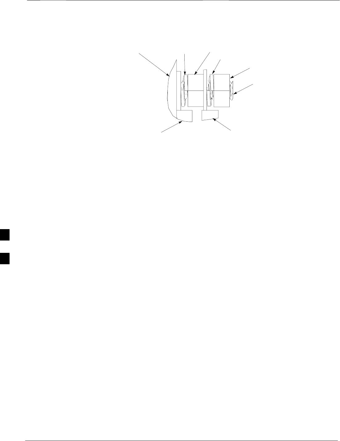
Earth Ground Cabling – continued
DRAFT
SCt300 1X BTS Hardware Installation, ATP, and FRU Procedures JAN 2002
6-12
Figure 6-8: Grounding Stud on Mounting Bracket
LOCK WASHER
NUT
NUT
LOCK WASHER
MOUNTING BRACKET
CUSTOMER UNIT
GROUND LUG
SITE I/O
GROUND LUG
GROUNDING STUD
6

Attaching the Site I/O Junction Box to the Unit
JAN 2002 6-13
SCt300 1X BTS Hardware Installation, ATP, and FRU Procedures
DRAFT
Objective
The objective of this procedure is to attach the Site I/O junction box to
the unit. The location for the Site I/O junction box is shown in
Figure 6-9.
If you do not mount a Site I/O Junction box to a unit, leave the installed
Site I/O caps on the Site I/O Junction box connectors.
Required Tools and Materials
The following tools and materials are necessary to do this procedure:
STorque driver wrench, 1/4–in. hex female drive, 0–10 N–M
ST30 Torx tamper bit
SSite I/O Junction box
Procedure to Attach the Site
I/O Junction Box to the Unit
Follow the procedure below to attach the site I/O junction box to the
unit.
Table 6-7: Procedure to Attach the Site I/O Junction Box to the Unit
Step Action
1Use a T30 TORX bit to remove Site I/O Cap from the Site I/O connector.
NOTE
Save Site I/O Cap for future use.
2Remove the Site I/O Plate from the Site I/O Junction Box.
3Attach the straight end of the Y–ground cable (cable L) or the Site I/O ground cable (cable B) to
the site I/O junction box. Use one M6x19 tamper–resistant screw. Torque to 5.0 N–m.
NOTE
The free end of the Site I/O junction box cable should be connected to the customer–supplied Site
I/O interface.
4The free end of the Site I/O junction box cable should be connected to the customer–supplied Site
I/O interface or to the Primary Surge Suppressor.
5Position the Site I/O junction box as shown in Figure 6-9.
6Insert the Site I/O junction box on to the housing, using the alignment feature on the housing.
7Use a T30 Torx tamper bit to tighten (but do not torque) the upper tamper resistant screw.
8Tighten but do not torque the lower tamper resistant screw.
9Use a T30 Torx tamper bit to torque the upper and lower screw to 5 N–m.
6
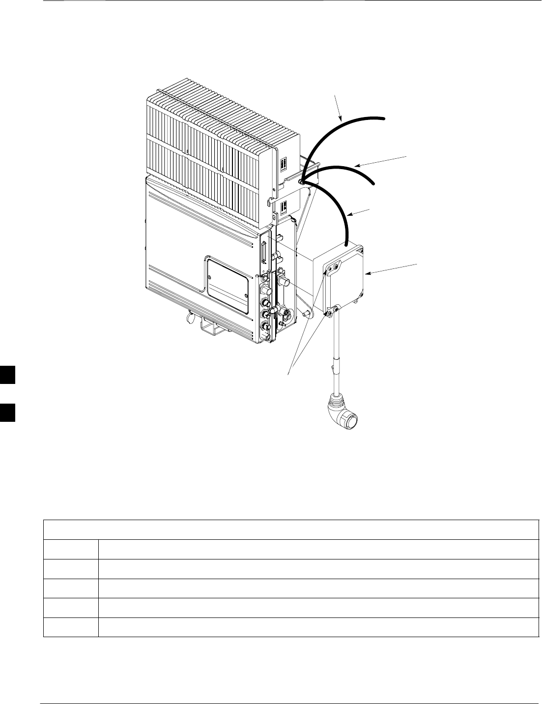
Attaching the Site I/O Junction Box to the Unit – continued
DRAFT
SCt300 1X BTS Hardware Installation, ATP, and FRU Procedures JAN 2002
6-14
Figure 6-9: Attaching the Site I/O Junction Box to the Unit
SITE I/O JUNCTION BOX
CAPTIVE SCREWS
Y–GROUND CABLE (CABLE L) OR,
SITE I/O GROUND CABLE (CABLE B)
MASTER GROUND
CABLE (CABLE Y)
TO SU (IF EQUIPPED)
Procedure to Attach a Site I/O
Cap to the Unit (optional)
Use the following procedure in Table 6-8 to attach a Site I/O Cap to the
unit.
Table 6-8: Procedure to Attach a Site I/O Cap to the Unit (optional)
Step Action
1Position the Site I/O cap, Motorola Part Number 1587667C06, over the Site I/O socket.
2Use a T30 Torx tamper bit to tighten (but do not torque) the upper tamper resistant screw.
3Tighten but do not torque the lower tamper resistant screw.
4Use a T30 Torx tamper bit to torque the upper and lower screw to 5 N–m.
6

Subscriber Unit (SU) Installation and Cabling
JAN 2002 6-15
SCt300 1X BTS Hardware Installation, ATP, and FRU Procedures
DRAFT
Objective
The objective of this procedure is to install the Subscriber Unit (SU) to
the unit and to install the necessary cables.
Cable Labels
The cable designations are referenced to Table 4-1 in the “Cable
Description” area of this chapter.
Required Tools and Materials
Required tools
STorque driver wrench
ST30 TORX tamper bit
S5/16–in. SMA 9 in–lb. break–away torque wrench
Motorola kits
The Motorola Kit described in Table 6-9 is required to do this procedure.
Table 6-9: External Subscriber Unit Kit – T529AA
Cable Qty. Part Number Description
n/a 1–4 SGLN5976A Subscriber Unit
P 1–4 3088120C03 SU RF cable
L 1–4 3087701C04 Y–Ground Cable (for external SU and Site I/O).
Motorola terminators
The following Motorola terminators in Table 6-10 are required to do this
procedure. The number of SU Terminators depends upon system
configuration.
Table 6-10: Terminations of Unused Connectors
Connector Motorola Part # Description
SU Digital 5887659C02 Terminator, Power
SC340 AC
SU Distribution 0187683C03 Terminator, SMA
(Microcell)
6
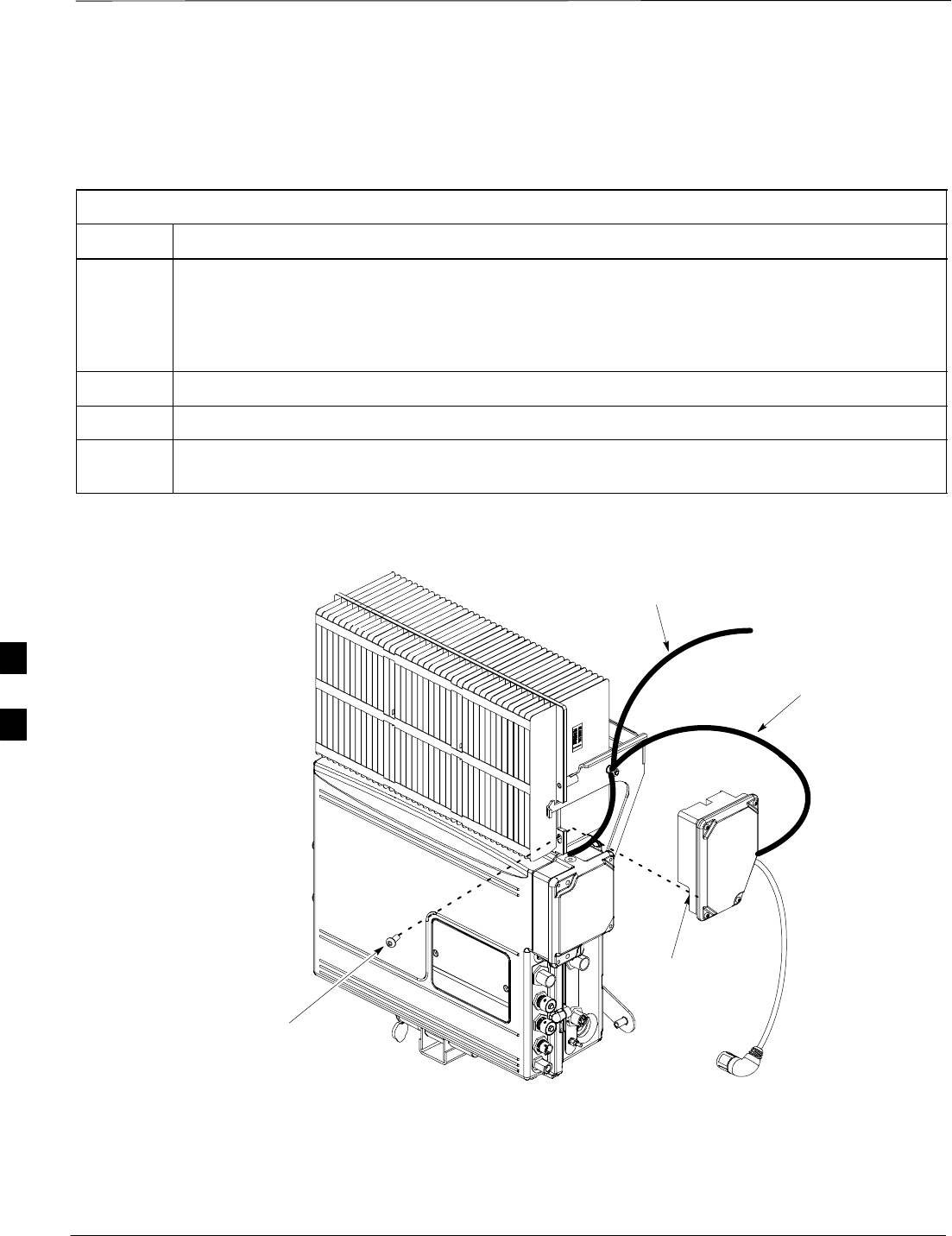
Subscriber Unit (SU) Installation and Cabling – continued
DRAFT
SCt300 1X BTS Hardware Installation, ATP, and FRU Procedures JAN 2002
6-16
Procedure to Install SU Box
Table 6-11 gives the procedure to install the SU box on a MicroCell unit.
You must install one SU on each unit at the BTS.
Table 6-11: Procedure to Install the SU Box
Step Action
1Attach one end of the Y–Ground cable (cable L) to the SU. Use one M6x19 tamper–resistant
screw. Torque to 5.0 N–m.
NOTE
If unit is not equipped with a Site I/O, then one end of the Y–ground cable will hang loose.
2Position the SU as shown in Figure 6-10.
3Insert the oval protrusion of the SU onto the slotted hole on the cooling fins.
4Use a torque driver and a T30 TORX bit to tighten the tamper–resistant screw. Tighten to 5.0
N–m.
Figure 6-10: Attaching Subscriber Unit (SU) to Unit
INSERT OVAL
PROTRUSION ONTO
SLOTTED HOLE OF
COOLING FINS
MASTER GROUND
CABLE (CABLE Y)
Y–GROUND CABLE
(CABLE L)
TAMPER–RESISTANT
SCREW
6
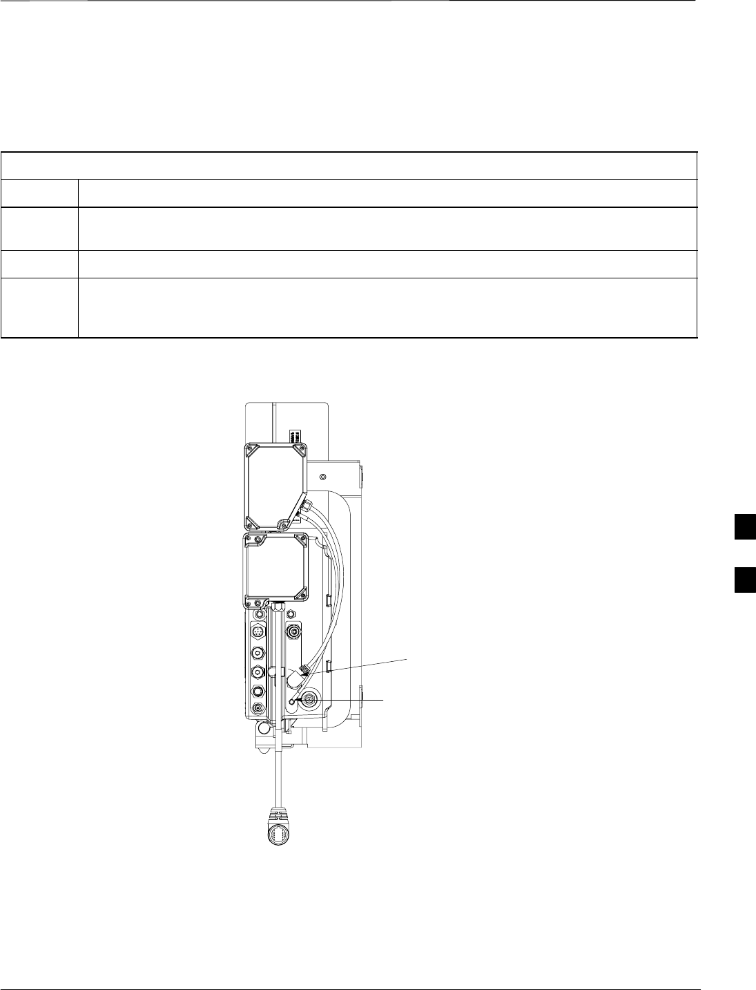
Subscriber Unit (SU) Installation and Cabling – continued
JAN 2002 6-17
SCt300 1X BTS Hardware Installation, ATP, and FRU Procedures
DRAFT
Procedure to Install SU Cabling
Table 6-11 gives the procedure to install the SU cabling on a MicroCell
unit.
Table 6-12: Procedure to Install the SU Cabling
Step Action
1Attach one end of the SU RF cable (cable P) to the SU 1 connector on the SU. Attach the other
end of cable P to the SU RF connector on the unit. Refer to Figure 6-11.
2Use the 5/16–in. SMA breakaway wrench to tighten the SMA connectors on the SU RF cable.
3Attach the free end of the SU Digital cable (cable Q) to the SU DIGITAL connector on the unit.
Refer to Figure 6-11. Hand tighten the SU Digital connector (you will hear soft clicks, this is
normal). When the red line on the connector on the unit is covered, the connection is complete.
Figure 6-11: Attaching SU Cables to Unit
SU DIGITAL CABLE (CABLE Q)
SU RF CABLE (CABLE P)
6
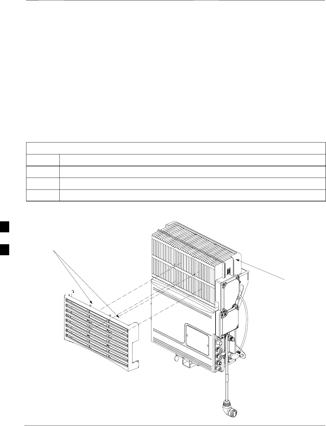
Attaching Front Fin Cover to Unit
DRAFT
SCt300 1X BTS Hardware Installation, ATP, and FRU Procedures JAN 2002
6-18
Objective
The objective of this procedure is to attach the front fin cover to the
MicroCell unit.
When to Use the Fin Covers
Always use fin covers for an indoor application.
Procedure to Attach the Front
Fin Cover to Unit
Follow the procedure in Table 6-13 to attach the front fin cover to the
unit. Refer to Figure 6-12.
Table 6-13: Procedure to Attach the Front Fin Cover to Unit
Step Action
1Center fin cover on the fins of the unit. See Figure 6-12 for snap locations.
2Align snap with center tab on fins.
3Push fin cover into place.
Figure 6-12: Attaching Front Fin Cover to Unit
MICROCELL FINS
LOCATION OF SNAPS TO ATTACH
FIN COVER TO UNIT
6

Attaching the Short Duration Battery to the Unit (optional)
JAN 2002 6-19
SCt300 1X BTS Hardware Installation, ATP, and FRU Procedures
DRAFT
Objective
The objective of this procedure is to attach the short duration battery to
the unit.
Required Tools and Materials
Attaching the battery to the unit requires:
ST30 Torx tamper bit, 1/4–in. hex
STorque driver wrench, 1/4–in. hex female drive, 0–10 N–M
STwo (2) Screws M6x19 (Motorola Part Number 0387541C03)
Procedure to Attach the Short
Duration Battery to the Unit
Follow the procedure in Table 6-14 to attach the short duration battery to
the unit. Refer to Figure 6-13.
Table 6-14: Procedure to Attach the Short Duration Battery to the Unit
Step Action
1Hold the battery in the position shown in Figure 6-13.
2The two holes at the end of the battery should align with the mounting holes on the unit. See
Figure 6-13.
3Start but do not tighten the M6x19 screws.
4Use a T30 Torx tamper bit wrench, 1/4–in. hex female drive, 0–10 N–M, to torque the screws to 5
N–M.
6
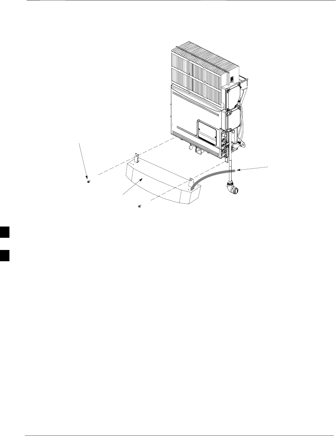
Attaching the Short Duration Battery to the Unit (optional) – continued
DRAFT
SCt300 1X BTS Hardware Installation, ATP, and FRU Procedures JAN 2002
6-20
Figure 6-13: Attach Short Duration Battery to Unit
M6X19 SCREWS (2)
CONNECT TO DC
INPUT CONNECTOR
WHEN BATTERY HAS
BEEN SECURED
SHORT DURATION
BATTERY
6

Short Duration Battery Cabling
JAN 2002 6-21
SCt300 1X BTS Hardware Installation, ATP, and FRU Procedures
DRAFT
Objective
The objective of this procedure is to attach the short duration battery
cable.
Battery Cable
The battery cable is part of the battery assembly. The same type
connector is used for the short duration battery and DC input cables.
Procedure to Install Short
Duration Battery Cable to the
Unit
Use the following procedure in Table 6-15 to attach the short duration
battery (DC input) cable to the DC input connector. Refer to
Figure 6-14. The cable should be connected before the solar cover is
attached.
The short duration battery should not be opened under any
circumstances. No wire termination is required by the user except
connection to the BTS, with the provided connector.
Table 6-15: Procedure to Install Short Duration Battery Cable to Unit
Step Action
1Ensure that the ground wire has a connection to unit and the Master Ground Bus (also called
Master Ground Plate).
2Verify that the DC power breaker is open. The white collar on the breaker is visible when it is
open.
3Place the round, black connector of the DC input cable onto the DC input connector on the BTS.
Refer to Figure 6-14. Turn the cable connector to align its key.
4Hand tighten the connector (a clicking sound is heard, this is normal). When the red line on the
connector on the unit is covered, connection is complete.
6
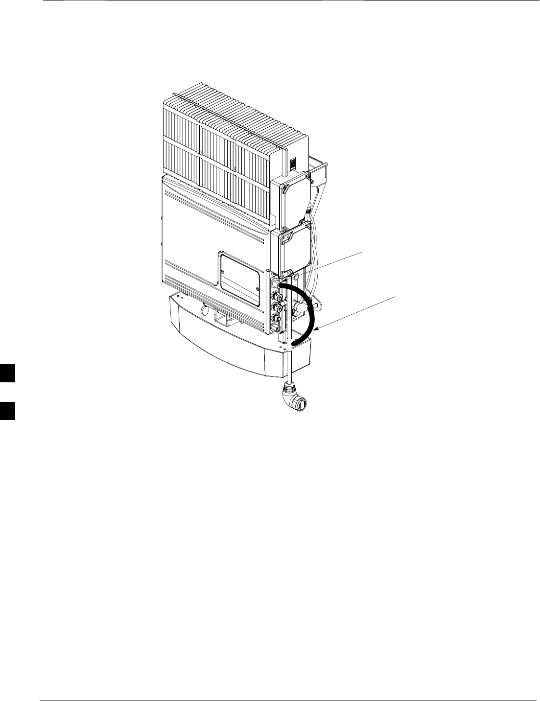
Short Duration Battery Cabling – continued
DRAFT
SCt300 1X BTS Hardware Installation, ATP, and FRU Procedures JAN 2002
6-22
Figure 6-14: Battery Cable Installation
DC INPUT CONNECTOR
BATTERY CABLE IS PART
OF BATTERY ASSEMBLY
6
AC Power Cabling
JAN 2002 6-23
SCt300 1X BTS Hardware Installation, ATP, and FRU Procedures
DRAFT
Objective
The objective of this procedure is to attach the AC input power cable to
the unit. Use this procedure only when AC power is used to power the
unit.
If the Primary Surge Suppressor is not used, the AC Installation Box is
required for all outdoor mounting applications.
This equipment uses dangerous voltages and is capable of
causing death. Use extreme caution when handling and
testing this equipment.
WARNING
Required Cables
The following cables in Table 4-1 are necessary to do this procedure:
Table 6-16: Required Cables for AC Input Power Cabling
Cable Qty. Part Number Description
S 1–4 3087854C02 AC input cable, 18 AWG, 5 m, is designed for 120–240 VAC power
input. Cable has Deutsche connector on both ends.
Power Cable and Connector
Signal Information
The AC input connector is located on the side of the unit as shown in
Figure 6-15. The unit is designed for 88–260 VAC power input.
Procedure to Connect AC Input
Power Cable to the Unit
Use the following procedure in Table 6-17 to connect the AC input cable
to the unit. The AC input cable should be connected before the solar
cover is attached.
Table 6-17: Procedure to Connect AC Power Cable to the Unit
Step Action
1Ensure that the ground wire has a connection to the Master Ground Bus (also called Master
Ground Plate).
2Verify that the AC power breaker is open. The white collar on the breaker is visible when it is
open.
3Place the round, black connector on the AC input cable (cable S) onto the AC input connector.
See Figure 6-15. Turn the cable connector to align its key.
4Hand tighten the connector (a clicking sound is heard, this is normal). When the red line on the
connector on the unit is covered, connection is complete.
6
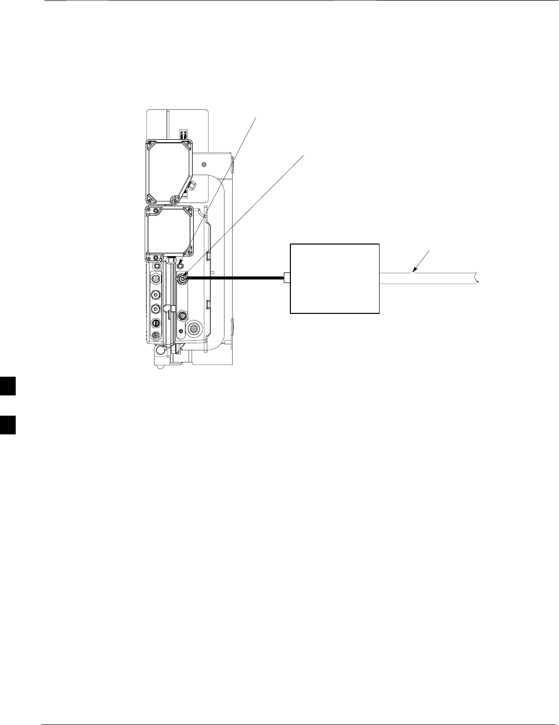
AC Power Cabling – continued
DRAFT
SCt300 1X BTS Hardware Installation, ATP, and FRU Procedures JAN 2002
6-24
Figure 6-15: AC Power Cabling Details
AC INSTALL BOX
OR AC POWER
SOURCE OR
OPTIONAL
PRIMARY SURGE
SUPPRESSOR
AC INPUT
CONNECTOR
AC POWER
BREAKER
S
AC CONDUIT
6
DC Power Cabling
JAN 2002 6-25
SCt300 1X BTS Hardware Installation, ATP, and FRU Procedures
DRAFT
Objective
The objective of this procedure is to attach the DC input cable to the
unit. Use this procedure only when DC power is used to power the unit.
This equipment uses dangerous voltages and is capable of
causing death. Use extreme caution when handling and
testing this equipment.
WARNING
Required Cables
The following cables in Table 6-18 are necessary to do this procedure.
Table 6-18: Required Cables for DC Input Power Cable Installation
Cable Qty. Part Number Description
U 1 3087854C04 DC input cable, 18 AWG, 5 m, is designed for 20 to 30 VDC power
input.
Power Cable and Connector
Signal Information
The DC input connector is located on the side of the unit. The unit is
designed for 20 to 30 VDC.
Procedure to Connect DC Input
Power Cabling to the Unit
Use the following procedure in Table 6-19 to connect the DC input cable
to the unit. Refer to Figure 6-16. The DC input cable should be
connected before the solar cover is attached.
Table 6-19: Procedure to Connect DC Input Power Cabling to the Unit
Step Action
1Ensure that the ground wire has a connection to the Master Ground Bus (also called Master
Ground Plate).
2Verify that the DC power breaker is open. The white collar on the breaker is visible when it is
open.
3Place the round, black connector of the DC input cable onto the DC input connector. See
Figure 6-16. Turn the cable connector to align its key.
4Hand tighten the connector (a clicking sound is heard, this is normal). When the red line on the
connector on the unit is covered, connection is complete.
6
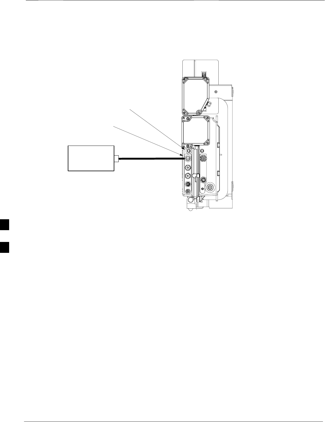
DC Power Cabling – continued
DRAFT
SCt300 1X BTS Hardware Installation, ATP, and FRU Procedures JAN 2002
6-26
Figure 6-16: DC Power Cabling Details
DC INPUT
CONNECTOR
DC POWER
SOURCE
DC POWER BREAKER
U
6
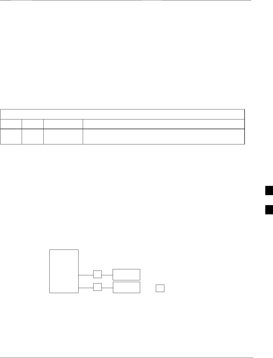
Antenna Cabling for Sites Equipped with Customer–Supplied Site I/O
Interface
JAN 2002 6-27
SCt300 1X BTS Hardware Installation, ATP, and FRU Procedures
DRAFT
Objective
The objective of this procedure is to attach the antenna cabling for one or
more units.
If your BTS is equipped with the optional Primary Surge Suppressor,
then proceed to the “Antenna Cabling for Sites Equipped with the
Optional Primary Surge Suppressor” procedure in Chapter 6.
Required Cables
The following cables in Table 6-20 are necessary to do this procedure.
Table 6-20: Required Cables for Antenna Cabling
Cable Qty. Part Number Description
C 1–8 Customer
Supplied Antenna cable, 50–Ohm coaxial terminated with at least one male,
N–type connector.
Procedure to Install Antenna
Cabling
The cabling is installed between the unit(s) and the external lightning
arrestors. If lightning arrestors are not present, it connects to the
antenna.
If your BTS has one unit, cable the unit as shown in Figure 6-17.
Torque the connectors to 4.3 N–M.
If your BTS has more than one unit (logical BTS), cable the unit as
shown in Figure 6-18, Figure 6-19, or Figure 6-20.
Figure 6-17: Antenna Cabling Details for One MicroCell Unit
ANT A
ANT B
MICROCELL 1
LA ANTENNA 2
TX/RX
B
LA ANTENNA 1
RX
B
LA = LIGHTNING ARRESTOR
KEY
6

Antenna Cabling for Sites Equipped with Customer–Supplied Site I/O
Interface – continued
DRAFT
SCt300 1X BTS Hardware Installation, ATP, and FRU Procedures JAN 2002
6-28
Figure 6-18: Antenna Cabling for Two MicroCells
ANT A
ANT B
RFT
ANT A
ANT B
RFT
LA
MICROCELL 1
MICROCELL 101
LA ANTENNA 2
TX/RX
LA ANTENNA 1
TX/RX
RFT
= LIGHTNING ARRESTOR
= 50 OHM RF TERMINATOR
KEY
C
C
Figure 6-19: Antenna Cabling for Three MicroCells
ANT A
ANT B
ANT A
ANT B
RFT
ANT A
ANT B
RFT
LA
LA
MICROCELL 1
MICROCELL 201
MICROCELL 101
ANTENNA 3
TX/RX
LA ANTENNA 4
RX
LA ANTENNA 2
TX/RX
LA ANTENNA 1
TX/RX
RFT
= LIGHTNING ARRESTOR
= 50 OHM RF TERMINATOR
KEY
C
C
C
C
6
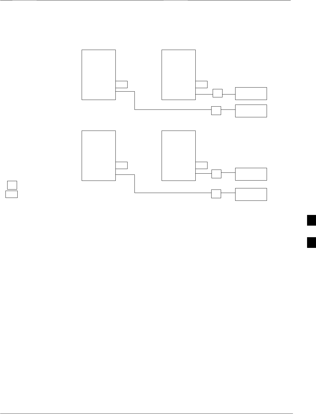
Antenna Cabling for Sites Equipped with Customer–Supplied Site I/O
Interface – continued
JAN 2002 6-29
SCt300 1X BTS Hardware Installation, ATP, and FRU Procedures
DRAFT
Figure 6-20: Antenna Cabling for Four MicroCells
ANT A
ANT B
RFT ANT A
ANT B
RFT
ANT A
ANT B
RFT ANT A
ANT B
RFT
LA
LA
MICROCELL 1
MICROCELL 201
MICROCELL 101MICROCELL 301
ANTENNA 3
TX/RX
LA ANTENNA 4
TX/RX
LA ANTENNA 2
TX/RX
LA ANTENNA 1
TX/RX
RFT
= LIGHTNING ARRESTOR
= 50 OHM RF TERMINATOR
KEY
C
C
C
C
6

Antenna Cabling for Sites Equipped with Optional Primary Surge
Suppressor
DRAFT
SCt300 1X BTS Hardware Installation, ATP, and FRU Procedures JAN 2002
6-30
Objective
The objective of this procedure is to attach the antenna cabling for one or
more units at a site equipped with the optional Primary Surge
Suppressor.
Cable Labels
The cable designations are referenced to Table 4-1 in the “Cable
Description” area of Chapter 4.
Required Cables
The following cables in Table 6-21 are necessary to do this procedure.
Table 6-21: Required Cables for Antenna Cabling
Cable Qty. Part Number Description
C 1–8 Customer
Supplied Antenna cable, 50–Ohm coaxial terminated with at least one male,
N–type connector.
D 2–6 Customer
Supplied Antenna cable, terminated with 2 male N–type connectors
Procedure to Install Antenna
Lightning Arrestors and
Antenna Cabling
Lightning arrestors are shipped/installed in the Primary Surge
Suppressor for one or two unit configurations. If you are expanding
from two to three or from three to four units, then you must install
lightning arrestors for units three and four. Refer to the procedure in
Table 6-22 to install antenna lightning arrestors.
If your BTS has one unit and is equipped with the Primary Surge
Suppressor, cable the unit as shown in Figure 6-22.
If your BTS has more than one unit and is equipped with the Primary
Surge Suppressor, cable the units as shown in Figure 6-23 through
Figure 6-25.
Table 6-22: Procedure to Install Antenna Lightning Arrestors
Step Action
1Remove the 3/4–in. nut and lock washer from N–type connector on antenna lightning arrestor.
Refer to Figure 6-21.
2Insert the antenna lightning arrestor through hole in mounting flange.
NOTENOTE
Antenna cable connectors may be connected to either side of the antenna protectors on the
Primary Surge Suppressor.
3Install the lockwasher and 3/4–in. nut on the N–type connector.
4Use a 3/4–in. wrench to tighten to 20 N–m.
6
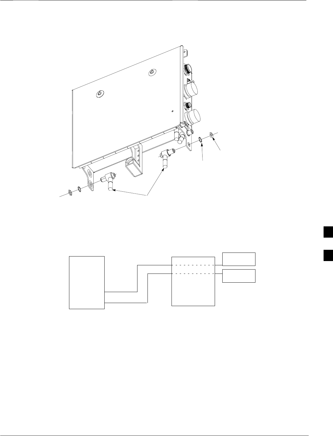
Antenna Cabling for Sites Equipped with Optional Primary Surge
Suppressor – continued
JAN 2002 6-31
SCt300 1X BTS Hardware Installation, ATP, and FRU Procedures
DRAFT
Figure 6-21: Installation of Third and Fourth Antenna Lightning Arrestors
ANTENNA LIGHTNING
ARRESTORS
LOCKWASHER
3/4–IN NUT
Figure 6-22: Antenna Cabling Details for MicroCell Equipped with Primary Surge Suppressor
ANT A
ANT B
MICROCELL 1
D
PRIMARY
SURGE
SUPPRESSOR
ANTENNA 1
TX/RX
ANTENNA 2
TX/RX
1
2
C
C
D
6
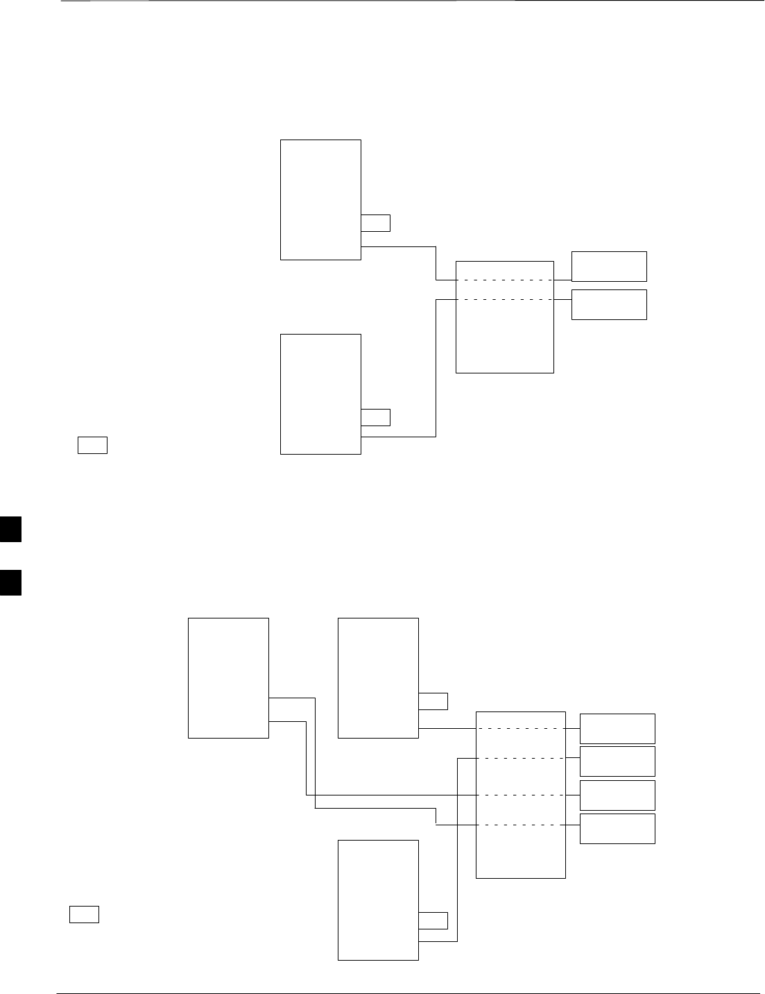
Antenna Cabling for Sites Equipped with Optional Primary Surge
Suppressor – continued
DRAFT
SCt300 1X BTS Hardware Installation, ATP, and FRU Procedures JAN 2002
6-32
Figure 6-23: Antenna Cabling for Two MicroCells Equipped with Primary Surge Suppressor
ANT A
ANT B
RFT
ANT A
ANT B
RFT
MICROCELL 1
MICROCELL 101
RFT = 50 OHM RF TERMINATOR
KEY
D
D
PRIMARY
SURGE
SUPPRESSOR
ANTENNA 1
TX/RX
ANTENNA 2
TX/RX
1
2
C
C
Figure 6-24: Antenna Cabling for Three MicroCells Equipped with Primary Surge Suppressor
ANT A
ANT B
ANT A
ANT B
RFT
ANT A
ANT B
RFT
MICROCELL 1
MICROCELL 201
MICROCELL 101
ANTENNA 3
TX/RX
ANTENNA 4
RX
ANTENNA 2
TX/RX
ANTENNA 1
TX/RX
RFT = 50 OHM RF TERMINATOR
KEY
D
DD
D
PRIMARY
SURGE
SUPPRESSOR
1
2
3
4
C
C
C
C
NOTE: YOU MUST INSTALL
ANTENNA PROTECTOR
6
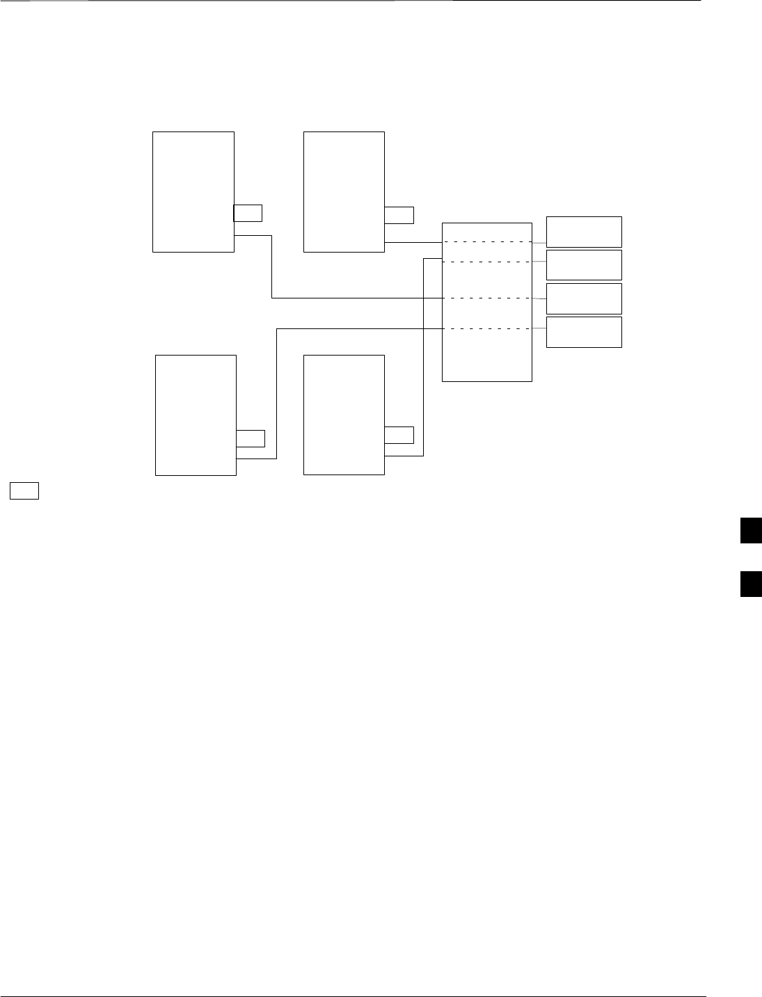
Antenna Cabling for Sites Equipped with Optional Primary Surge
Suppressor – continued
JAN 2002 6-33
SCt300 1X BTS Hardware Installation, ATP, and FRU Procedures
DRAFT
Figure 6-25: Antenna Cabling for Four MicroCells Equipped with Primary Surge Suppressor
ANT A
ANT B
ANT A
ANT B
RFT
ANT A
ANT B
RFT
MICROCELL 1MICROCELL 201
MICROCELL 101
ANTENNA 3
TX/RX
ANTENNA 4
TX/RX
ANTENNA 2
TX/RX
ANTENNA 1
TX/RX
RFT = 50 OHM RF TERMINATOR
KEY
DD
D
PRIMARY
SURGE
SUPPRESSOR
ANT A
ANT B
MICROCELL 301
RFT
RFT
D
1
2
3
4
C
C
C
C
6

MIB Cabling for Multi–Unit Logical BTS Configurations
DRAFT
SCt300 1X BTS Hardware Installation, ATP, and FRU Procedures JAN 2002
6-34
Overview
The objective of this procedure is to attach the MIB cabling for a
multi–unit logical BTS configuration.
Cable Labels
The cable designations are referenced in Table 4–1 in the “Cable
Descriptions” procedure in Chapter 4.
Required Tools and Equipment
Motorola parts
The following terminators in Table 6-23 are necessary to do this
procedure for a single–unit installation and are shipped with the unit:
Table 6-23: MIB Terminators
Quantity Part Number Description
3 3009865S04 Dust cap
1 3009865S02 Terminator, MIB (Microcell)
Motorola kits for multi–unit installations
Table 6-24 through Table 6-31 give the Motorola kit numbers, cable
descriptions and part numbers for the Motorola kits required to perform
a multi–unit installation. Several kits are available depending upon the
carrier installation.
Table 6-24: MicroCell Expansion Kit for Units 1 to 2 Short MIB A (Cubicle) – T448B
Cable Qty. Motorola Part
Number Description
n/a 2 5882106P01 50 Ohm Antenna Terminator
A 1 3087701C02 Ground cable, 8 -AWG, insulated copper wire. Requires one ring lug
connector.
K 1 3087707C09 MIB A cable (short, 1m; micro)
Table 6-25: Microcell Expansion Kit for Units 1 to 2 Long MIB A (Non–Cubicle) – T448A
Cable Qty. Motorola Part
Number Description
n/a 2 5882106P01 50 Ohm Antenna Terminator
A 1 3087701C02 Ground cable, 8 -AWG, insulated copper wire. Requires one ring lug
connector.
E 1 3087707C03 MIB A cable (current, 2m; micro)
6

MIB Cabling for Multi–Unit Logical BTS Configurations – continued
JAN 2002 6-35
SCt300 1X BTS Hardware Installation, ATP, and FRU Procedures
DRAFT
Table 6-26: Microcell (800 MHz) Expansion Kit for Units 2 to 3 Current 2m MIB B – T448AR
Cable Qty. Motorola Part
Number Description
A 1 3087701C02 Ground cable, 8 -AWG, insulated copper wire. Requires one ring lug
connector.
F 1 3087707C04 MIB B cable (current, 2m)
n/a 2 8009573X06 Lightning arrestor
Table 6-27: Microcell (800 MHz) Expansion Kit for Units 2 to 3 Long 5m MIB B – T448AS
Cable Qty. Motorola Part
Number Description
A 1 3087701C02 Ground cable, 8 -AWG, insulated copper wire. Requires one ring lug
connector.
I 1 3087707C07 MIB B cable (long, 5m)
n/a 2 8009573X06 Lightning arrestor
Table 6-28: Microcell (1.9 GHz) Expansion Kit for Units 2 to 3 Current 2m MIB B – T448AY
Cable Qty. Motorola Part
Number Description
A 1 3087701C02 Ground cable, 8 -AWG, insulated copper wire. Requires one ring lug
connector.
F 1 3087707C04 MIB B cable (current, 2m)
n/a 2 8009573X01 Lightning arrestor
Table 6-29: Microcell (1.9 GHz) Expansion Kit for Units 2 to 3 Long 5m MIB B – T448AZ
Cable Qty. Motorola Part
Number Description
A 1 3087701C02 Ground cable, 8 -AWG, insulated copper wire. Requires one ring lug
connector.
I 1 3087707C07 MIB B cable (long, 5m)
n/a 2 8009573X01 Lightning arrestor
Table 6-30: Microcell Expansion Kit for Units 3 to 4 Current 2m MIBs A and C – T448H
Cable Qty. Motorola Part
Number Description
A 1 3087701C02 Ground cable, 8 -AWG, insulated copper wire. Requires one ring lug
connector.
n/a 2 5882106P01 50 Ohm Antenna Terminator
E 1 3087707C03 MIB A cable (current, 2m; micro)
G 1 3087707C05 MIB C cable (current, 2m)
6
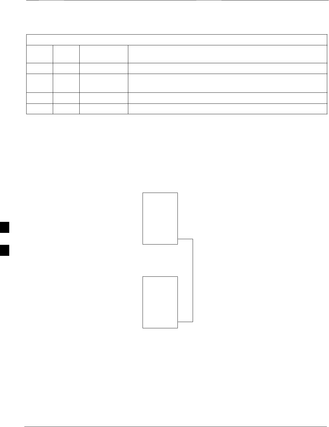
MIB Cabling for Multi–Unit Logical BTS Configurations – continued
DRAFT
SCt300 1X BTS Hardware Installation, ATP, and FRU Procedures JAN 2002
6-36
Table 6-31: Microcell Expansion Kit for Units 3 to 4 Longer 5M MIBs A and C – T448G
Cable Qty. Motorola Part
Number Description
n/a 2 5882106P01 50 Ohm Antenna Terminator
A 1 3087701C02 Ground cable, 8 -AWG, insulated copper wire. Requires one ring lug
connector.
E 1 3087707C03 MIB A cable (current, 5m; micro)
J 1 3087707C08 MIB C cable (long, 5m)
Procedure to Install MIB
Cabling
Cable the units as shown in Figure 6-28, Figure 6-27 or Figure 6-26.
Refer to the “Connector Locations” procedure in this chapter. Make sure
to terminate any unused connectors.
Figure 6-26: MIB Cabling for Two Units
UNIT 1
UNIT 101
MIB C
MIB B
MIB A
MIB C
MIB B
MIB A
E/1 MIB
OR
K/1 MIB
6
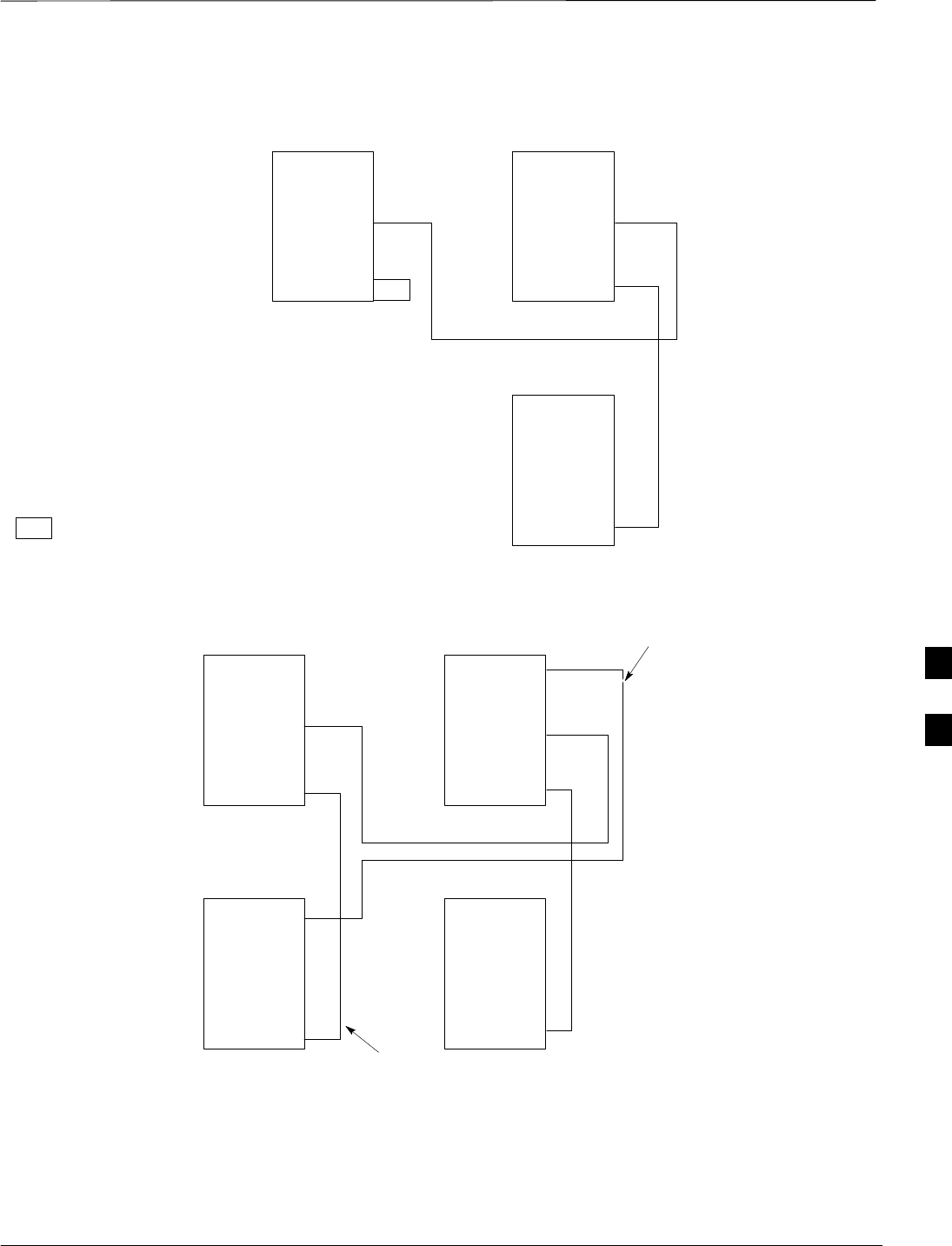
MIB Cabling for Multi–Unit Logical BTS Configurations – continued
JAN 2002 6-37
SCt300 1X BTS Hardware Installation, ATP, and FRU Procedures
DRAFT
Figure 6-27: MIB Cabling for Three Units
MT = MIB TERMINATOR
KEY
UNIT 1UNIT 201
UNIT 101
MIB C
MIB B
MIB A
MIB C
MIB B
MIB A
MIB C
MIB B
MIB A
MT
NOTE: MIB TERMINATOR
USED ON MICROCELL MIB A
CONNECTOR ONLY
E/1 MIB OR
K/1 MIB
F/1 MIB OR
I/1 MIB
Figure 6-28: MIB Cabling for Four Units
UNIT 1UNIT 301
UNIT 101UNIT 201
MIB C
MIB B
MIB A
MIB C
MIB B
MIB A
MIB C
MIB B
MIB A
MIB C
MIB B
MIB A
E/1 MIB OR
K/1 MIB
E/1 MIB OR
K/1 MIB
G/1 MIB
F/1 MIB
6
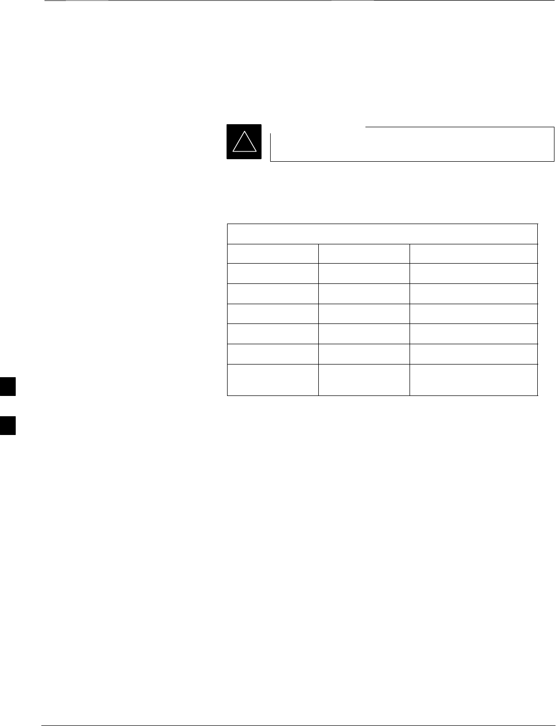
Terminating Unused Connections
DRAFT
SCt300 1X BTS Hardware Installation, ATP, and FRU Procedures JAN 2002
6-38
Objective
The objective of this procedure is to terminate any unused connections.
Terminate all unused connections.
IMPORTANT
*
List of Terminators for Unused
Connections
Table 6-32: List of Terminators for Unused Connections
Connector Motorola Part # Description
AC Input 5887659C02 Terminator, AC
DC Input 5887659C04 Terminator, DC
MIB A 3009865S02 Terminator, MIB
MIB B, C 3009865S04 Cap, MIB
SU Distribution 0187683C02 Terminator, SMA
SU Digital 5887659C02 Terminator, Power
SC300 AC
Procedure
The unit is shipped with the above terminators. Verify that a terminator
is on each unused connector. Tighten the SMA terminators using a
5/16 Breakaway 9 in. lb. Hand tighten all other terminators.
6

Powering on the Unit and Mounting the Solar Cover
JAN 2002 6-39
SCt300 1X BTS Hardware Installation, ATP, and FRU Procedures
DRAFT
Objective
The objective of this procedure is to power on the unit and mount the
solar cover on the chassis.
You May Want to Wait
Do not mount the front solar cover on the unit if you wish to perform the
Acceptance Test Procedures (ATP). Otherwise, mount the front solar
cover until you perform the ATP.
Required Tools and Materials
The following tamper–resistant keys are required to do this procedure.
SKey for tamper–resistant stud (provided) for the solar cover.
SKey for tamper–resistant locks (provided) for the Primary Surge
Suppressor.
Procedure to Power On the
Unit and Mount Solar Cover
Refer to the procedure in Table 6-33 to power on the unit and mount the
solar cover.
Table 6-33: Procedure to Power on the Unit and Mount the Solar Cover
Step Action
1n WARNING
Make sure the unit is properly grounded and that all connections are connected before powering
on unit.
on unit.
If not applying AC power, go to step 2. If applying AC power, push down on the AC power
breaker until it clicks and remains down. The white collar on the breaker is not visible when the
breaker is closed.
2If not applying DC power or providing for battery backup, go to step 3. If applying DC power or
have short or long duration batteries present, push down on the DC power breaker until it clicks
and remains down. The white collar on the breaker is not visible when the breaker is closed.
3Position the solar cover so the cooling vents are at the top and place the solar cover on the unit.
Use the key to tighten the four tamper–resistant studs (two on each side). Refer to Figure 6-29.
Procedure to Power On the
Surge Suppressor, the Unit,
and Mount the Solar Cover
If your BTS is equipped with the Primary Surge Suppressor, refer to the
procedure in Table 6-34 to power on the unit and mount the solar cover.
Table 6-34: Procedure to Power on the Surge Suppressor, the Unit, and Mount the Solar Cover
Step Action
1If closed, open the front cover of the Primary Surge Suppressor. Use the tamper–resistant key and
turn both the locks counter–clockwise. Refer to Figure 6-29.
. . . continued on next page
6
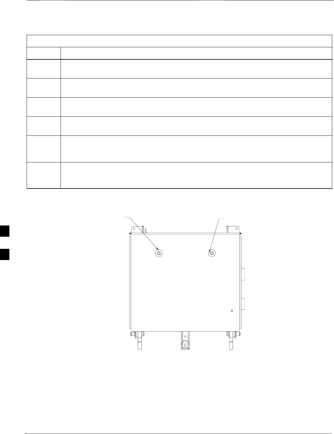
Powering on the Unit and Mounting the Solar Cover – continued
DRAFT
SCt300 1X BTS Hardware Installation, ATP, and FRU Procedures JAN 2002
6-40
Table 6-34: Procedure to Power on the Surge Suppressor, the Unit, and Mount the Solar Cover
Step Action
2If not applying AC power, go to step 6. If applying AC power, push the main AC power breaker
on the Surge Suppressor to the “On“ position. Refer to Figure 6-30.
3Push the AC power breakers for each individual carrier to the “On” position. All unused power
breakers must be in the “Off” position.
4Close the Primary Surge Suppressor door. Use the tamper–resistant key to turn the locks
clockwise to the “Locked” position.
5Push down on the AC power breaker on the unit until it clicks and remains down. The white
collar on the breaker is not visible when the breaker is closed.
6If not applying DC power or providing for battery backup, go to step 7. If applying DC power or
have short or long duration batteries present, push down on the DC power breaker until it clicks
and remains down. The white collar on the breaker is not visible when the breaker is closed.
7Position the solar cover so the cooling vents are at the top and place the solar cover on the unit.
Use the tamper–resistant key to tighten the four screws (two on each side) to 2.2 N–M. Refer to
Figure 6-31.
Figure 6-29: Lock Positions on Primary Surge Suppressor
LATCHED POSITION UNLATCHED POSITION
6
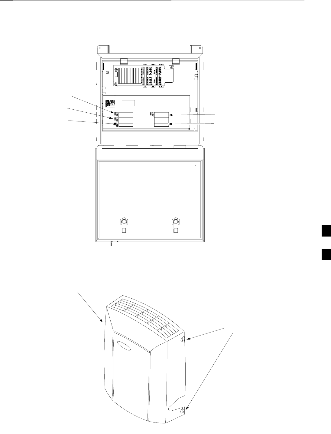
Powering on the Unit and Mounting the Solar Cover – continued
JAN 2002 6-41
SCt300 1X BTS Hardware Installation, ATP, and FRU Procedures
DRAFT
Figure 6-30: Location of AC Power Breakers on Primary Surge Suppressor
AC POWER BREAKER
CARRIER 1
AC POWER BREAKER
CARRIER 2
AC POWER BREAKER
CARRIER 3
AC POWER BREAKER
CARRIER 4
MAIN INPUT BREAKER
NOTE: INTERNAL CABLING
NOT SHOWN FOR CLARITY
Figure 6-31: Front Solar Cover
FRONT COVER
MOUNTING
SCREWS (4)
6

Site Cleanup
DRAFT
SCt300 1X BTS Hardware Installation, ATP, and FRU Procedures JAN 2002
6-42
Remove Protective Covering
Remove any antistatic plastic or cloth sheeting that was used to cover the
equipment.
Lighting Fixtures
Remove the masking tape from the fluorescent light fixtures.
Tools
Place all hand and power tools in the installation tool kit or other
appropriate place. Note any tools that need replacement, cleaning, or
adjustment.
Materials
Place any leftover materials in a location specified by the site manager.
Remove Debris
Remove any packing material.
Ensure that all scrap materials have been removed from any tables or
stands.
Clean/sweep the floor. Ensure that all alignment marks have been
removed.
Environment
Remove any temporary weather protection used for installation.
Check that all covers are in place.
Check that the power connections are tight.
Organize any items (manuals, materials, etc.) left on site and place them
in a location specified by the site manager.
Check that the unit lock is secure and key is removed.
Check that solar cover is secure.
Verify that cabling is properly secured between unit and enclosures.
6

Installation Completion Checklist
JAN 2002 6-43
SCt300 1X BTS Hardware Installation, ATP, and FRU Procedures
DRAFT
Directions
Fill out the installation completion checklist and make any necessary
copies. You may copy this check sheet as needed.
Installation Completion
Checklist
Date Hardware Installation Completed: ________________________
Site:___________________________________________________
Serial Number(s):_________________________________________
______________________________________________________
Checklist Completed By:____________________________________
Checklist Reviewed By:_____________________________________
Table 6-35: Installation Completion Checklist
Status No. Item Notes
1Air flow clearance requirements are met.
2Equipment is not damaged.
3Mounting bracket is level and secure.
4Back solar cover (if applicable) is securely
attached to the mounting bracket.
5RGPS head and mast are secure.
6RGPS head has a clear view of the sky and is
not in a location which accumulates debris.
Make sure the RGPS is located away from
the BTS transmit antenna.
7Mounting bracket is connected to the Master
ground.
8The connection to the AC source is secure (if
applicable).
9The AC source is protected by a lightning
arrestor (if applicable).
10 The connection to the DC source is secure (if
applicable).
11 The connection to the battery is secure (if
applicable).
12 The connection to the auxiliary device is
secure (if applicable).
13 The antenna connections are secure.
. . . continued on next page
6

Installation Completion Checklist – continued
DRAFT
SCt300 1X BTS Hardware Installation, ATP, and FRU Procedures JAN 2002
6-44
Table 6-35: Installation Completion Checklist
Status NotesItemNo.
14 The antenna cables are protected by lightning
arrestors (if applicable).
15 Customer input alarm connections are
complete between the Site I/O cable and the
Site I/O interface(s).
16 RGPS connections are complete between the
Site I/O cable and the Site I/O interface(s).
17 Phone (modem) connections are complete
between the Site I/O cable and the Site I/O
interface(s).
18 Span connections are complete between the
Site I/O cable and the Site I/O interface(s).
19 Span, phone, and RGPS connections are
protected by lightning arrestors (if
applicable).
20 The RGPS/HSO cabling for multi–BTS
configurations is secure (if applicable).
21 The span line daisy chain cabling for
multi–BTS configurations is secure.
22 The RGPS ground lead is connected to the
BTS digital ground reference.
23 Fin covers are secure.
24 Installation hardware is removed.
25 The lock is in place and the key removed.
26 The site I/O junction box is secure.
27 The short–duration battery is secure (if
applicable).
28 The short–duration battery cable (DC input
cable) is secure (if applicable).
29 The earth ground connection is secure
between the site I/O junction box and the
mounting bracket.
30 The AC input cable is securely attached to the
AC input connector (if applicable).
31 The DC input cable is securely attached to the
DC input connector (if applicable).
. . . continued on next page
6

Installation Completion Checklist – continued
JAN 2002 6-45
SCt300 1X BTS Hardware Installation, ATP, and FRU Procedures
DRAFT
Table 6-35: Installation Completion Checklist
Status NotesItemNo.
32 The DC output cable is securely attached to
the DC output connector (if applicable).
33 The unit–to–unit SU cabling is secure (if
applicable).
34 The unit–to–unit MIB cabling is secure (if
applicable)
35 The antenna N–type connectors are securely
attached to the antenna A and B connectors.
36 All unused ports are properly terminated.
37 All cables are dressed and tied.
38 The external power source (AC or DC) is
active.
39 The AC and/or DC power breakers on the
BTS are engaged (pushed in).
40 The front solar cover is secure (if applicable).
41 The auxiliary device is switched on (if
applicable).
42 The site is cleaned, swept and trash removed.
43 The site specific documentation is present at
the site.
6

Installation Completion Checklist – continued
DRAFT
SCt300 1X BTS Hardware Installation, ATP, and FRU Procedures JAN 2002
6-46
Notes
6