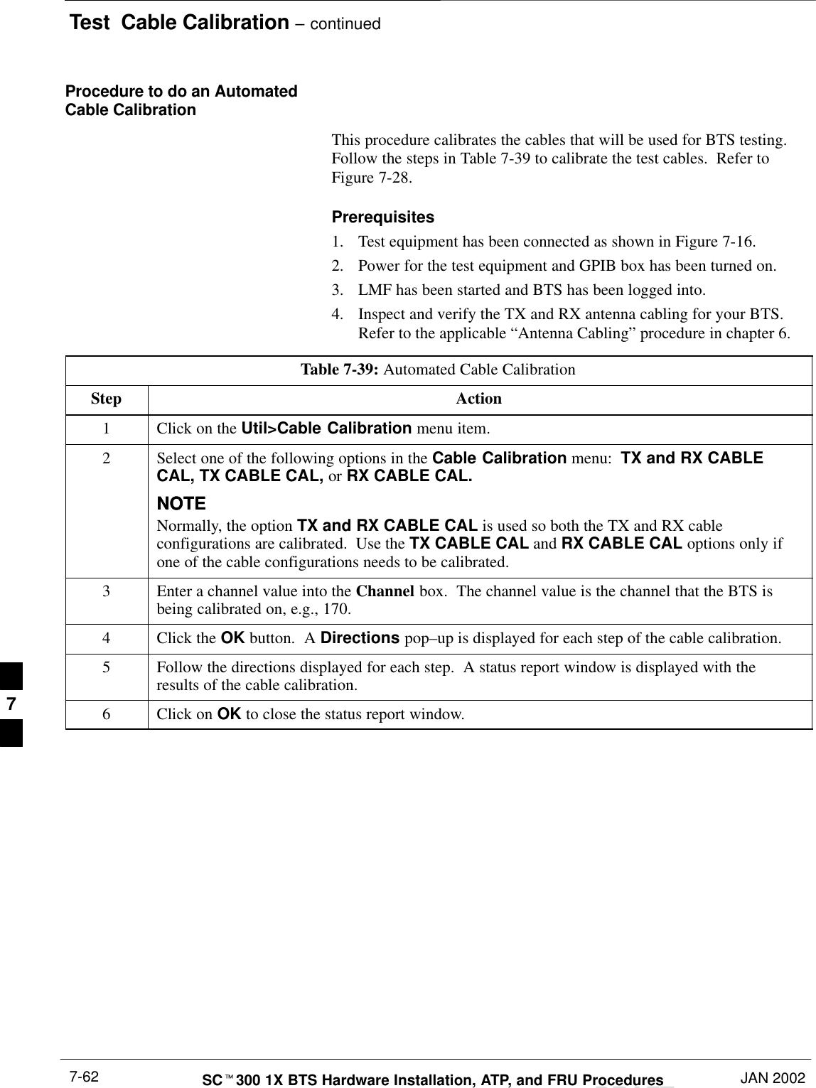
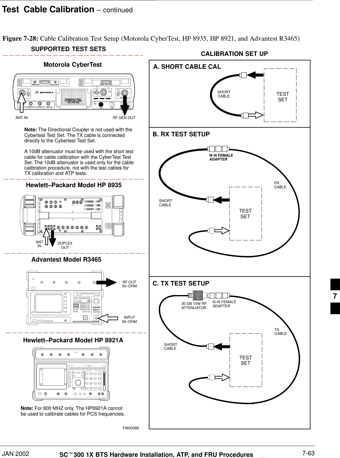
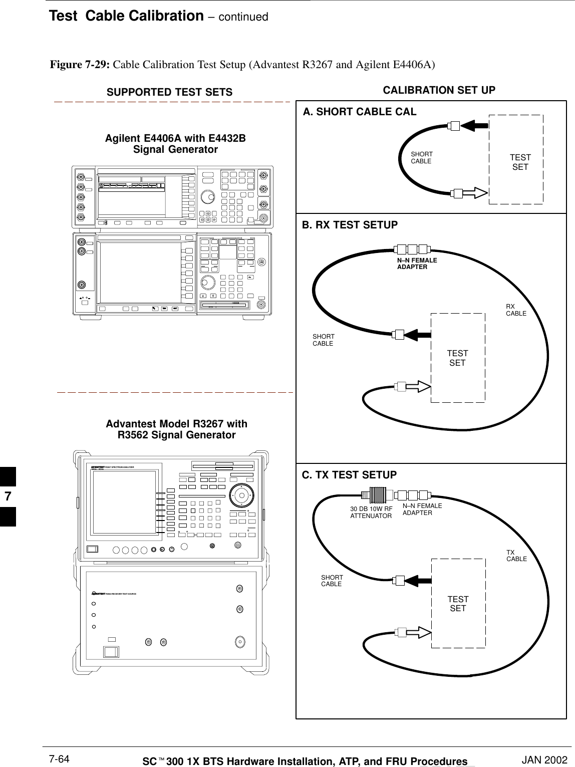
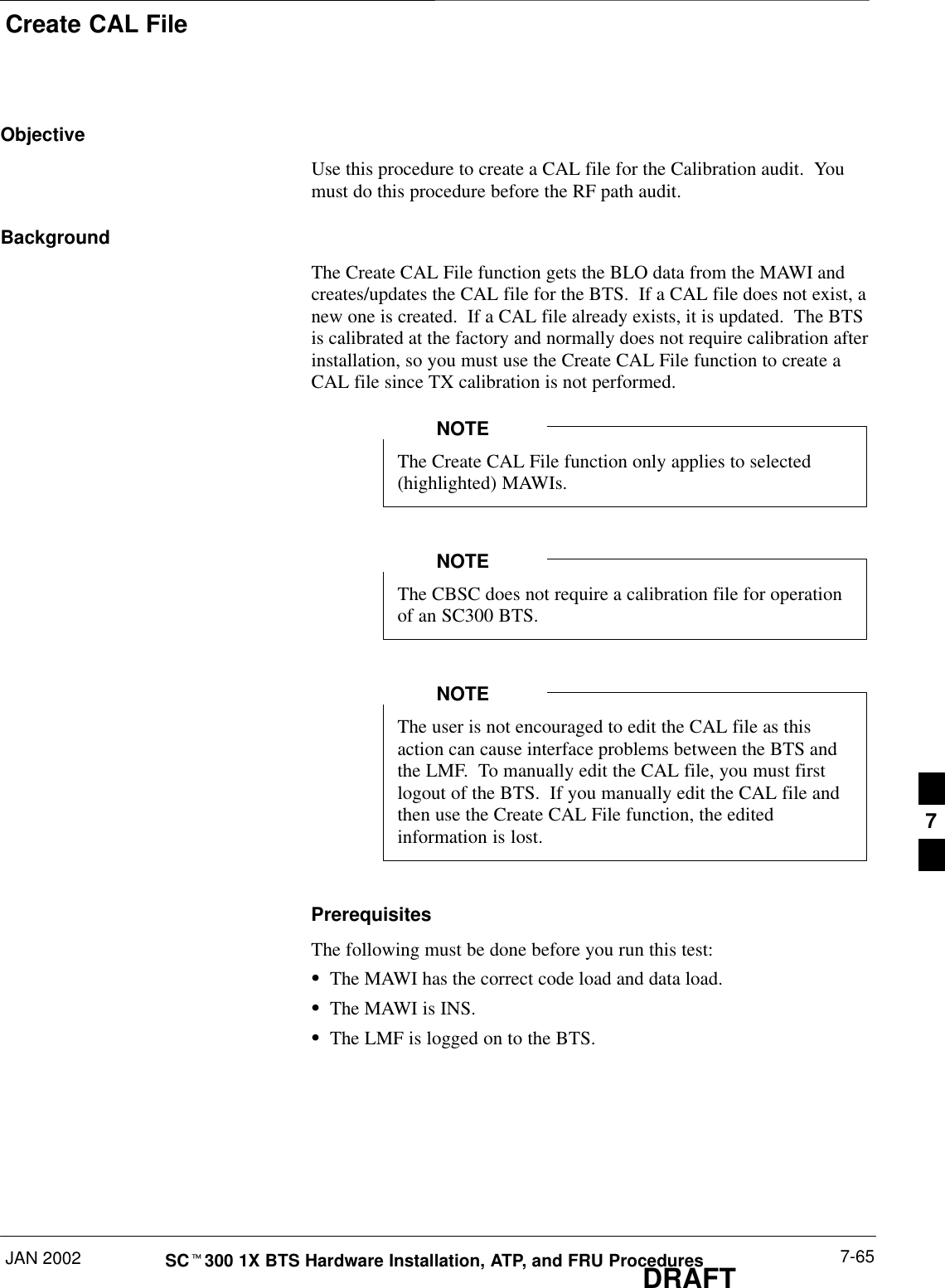
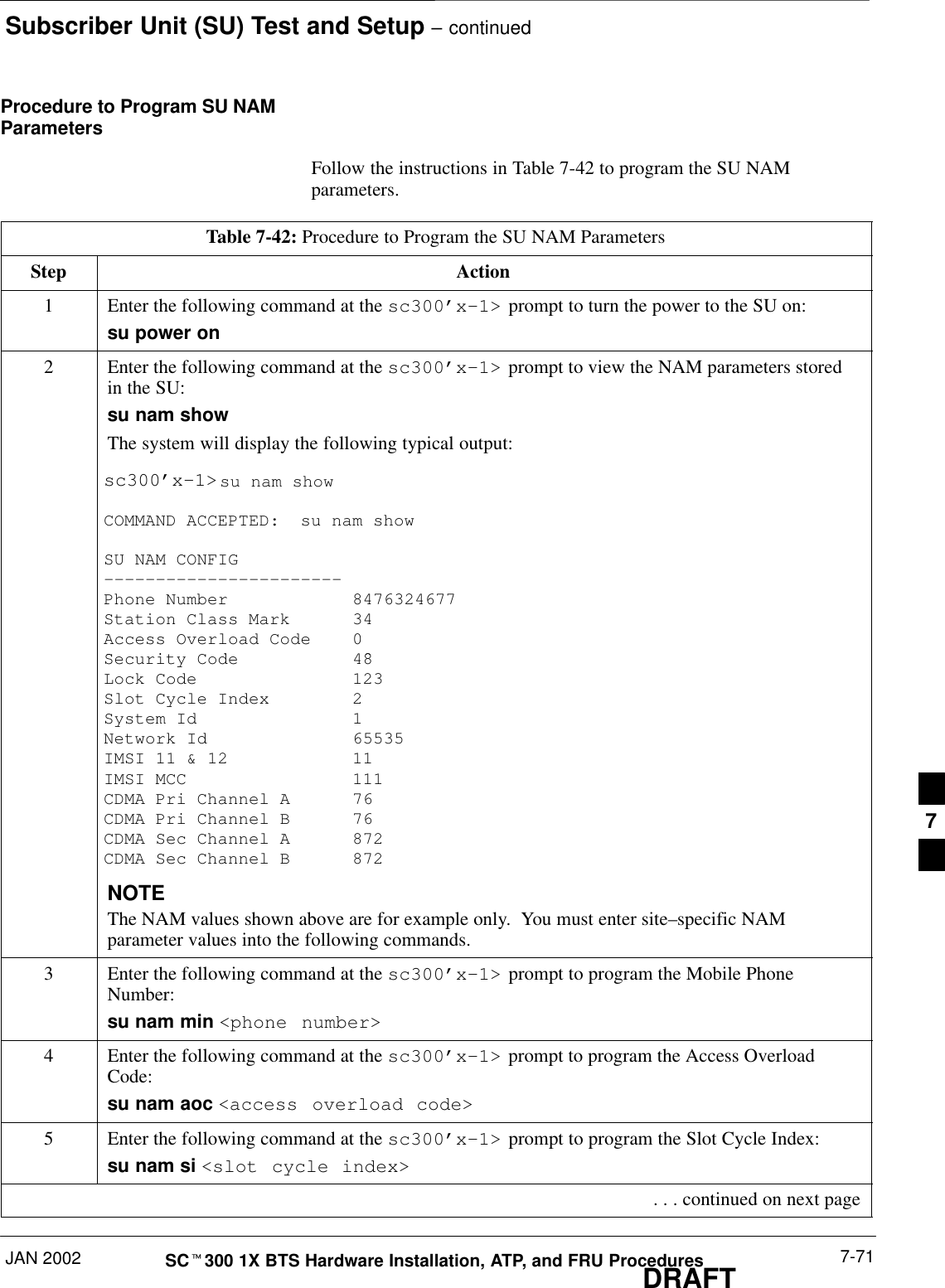
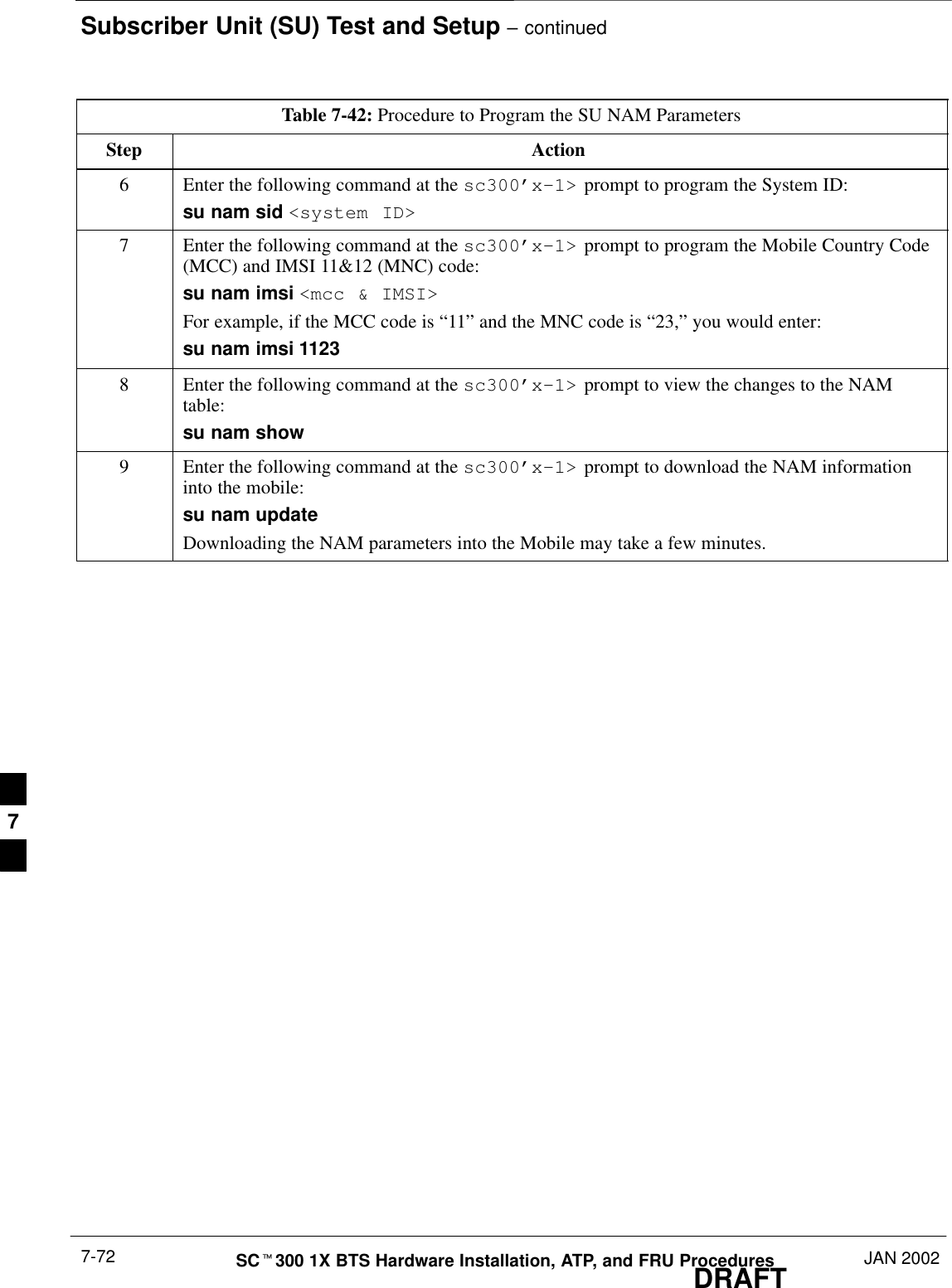
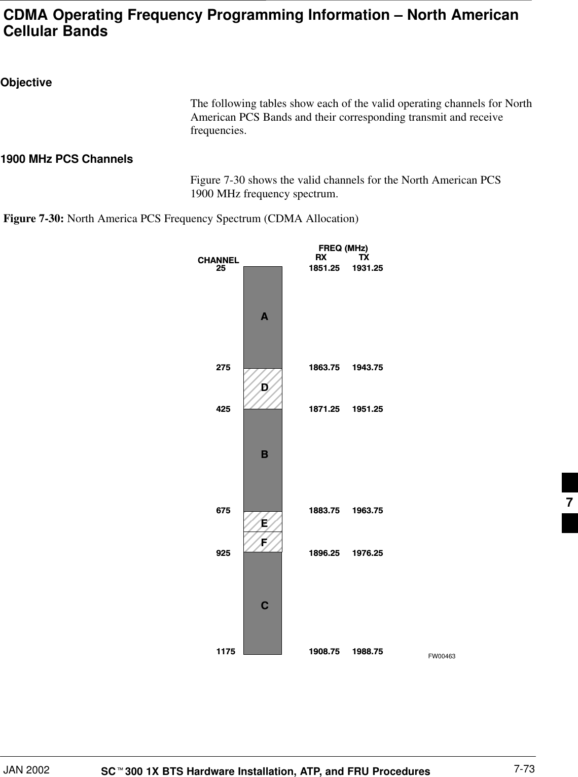
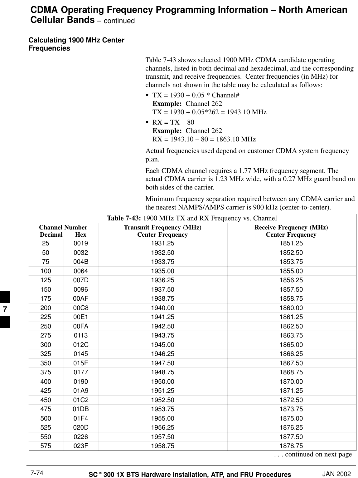
Nokia Solutions and Networks T6CB1 SC300 1X Microcell @ 1.9 GHz User Manual 3 of 3

Nokia Solutions and Networks SC300 1X Microcell @ 1.9 GHz Users Manual 3 of 3
Contents

Users Manual 3 of 3
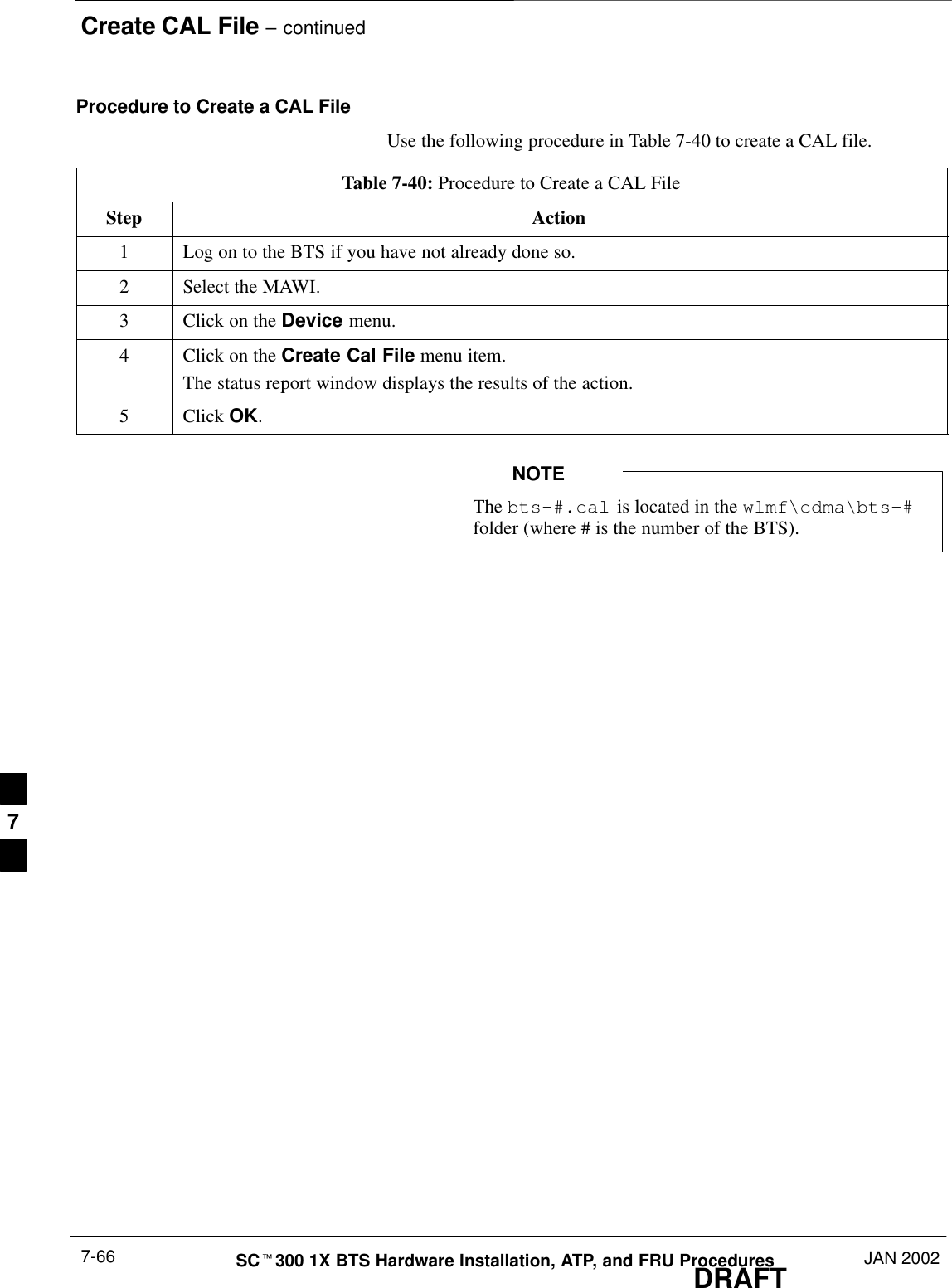
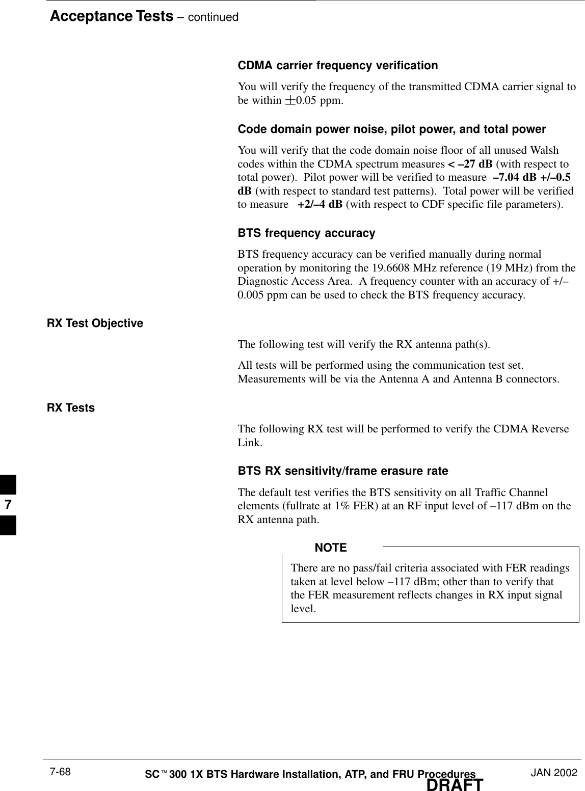
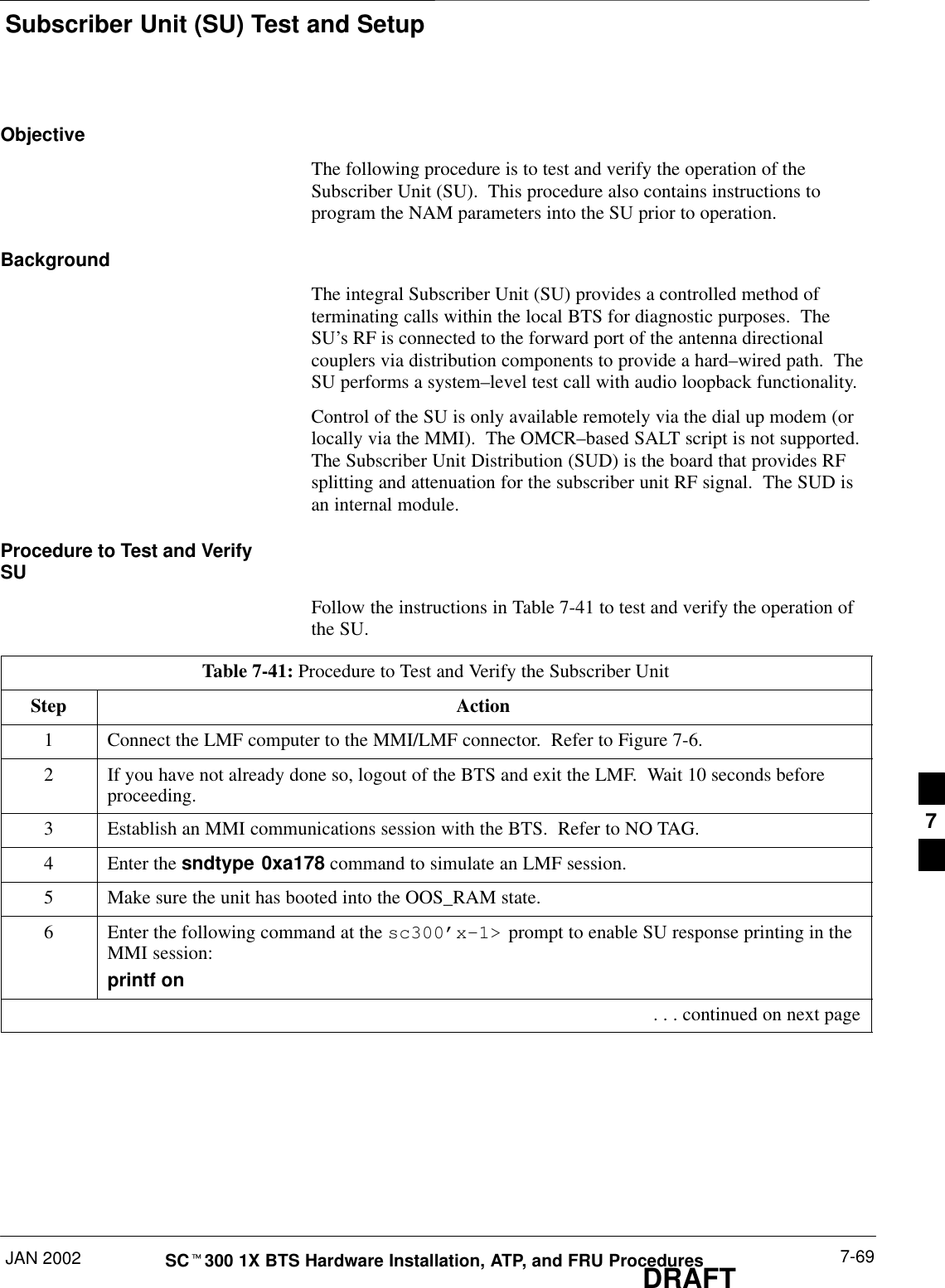
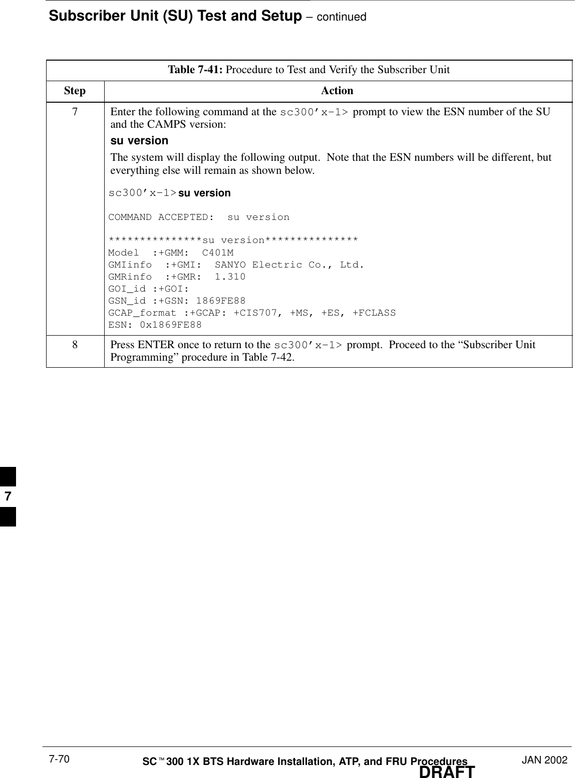
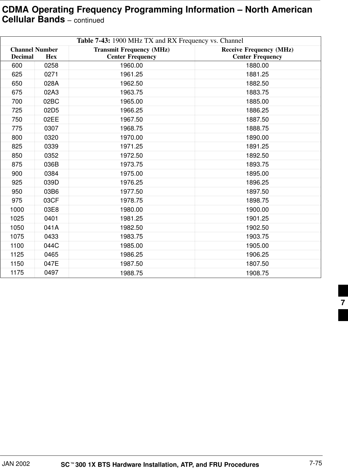
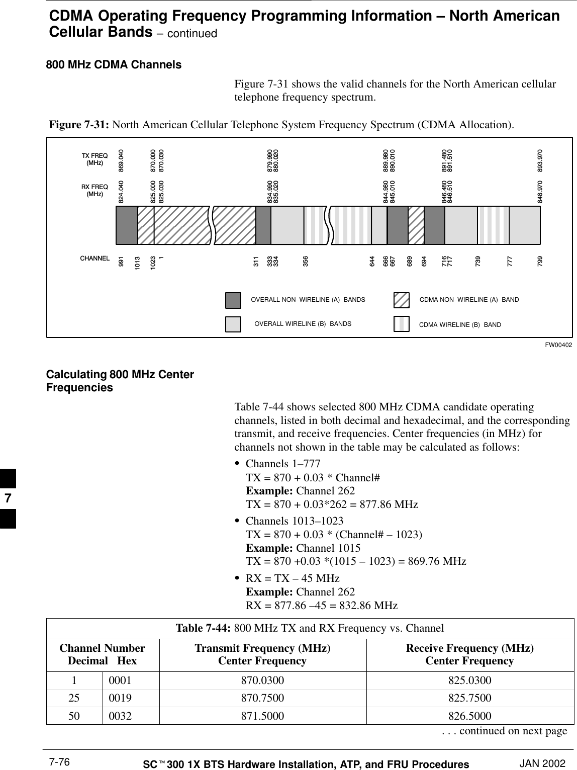
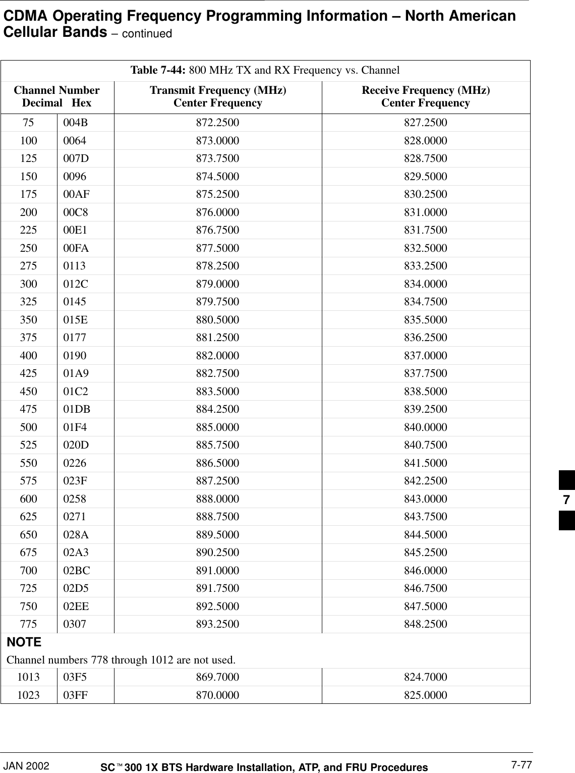
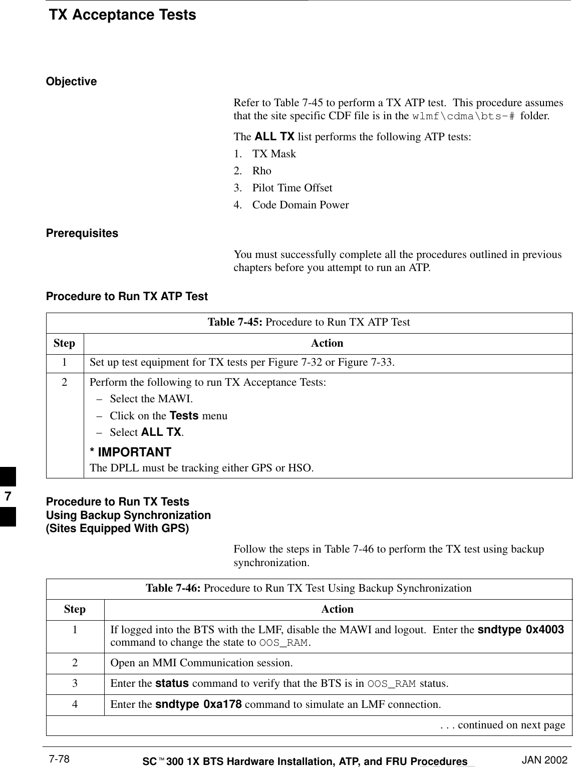
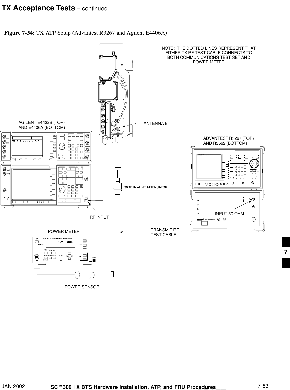
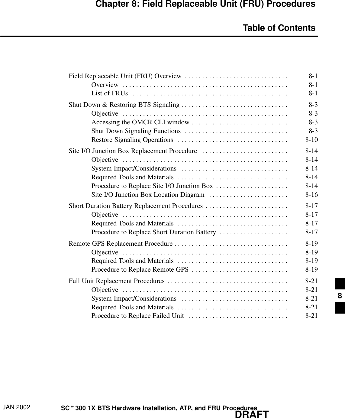
JAN 2002 SCt300 1X BTS Hardware Installation, ATP, and FRU ProceduresDRAFTChapter 7: Optimization and Optional Acceptance Test Procedures (ATP)Table of ContentsATP Overview 7-1. . . . . . . . . . . . . . . . . . . . . . . . . . . . . . . . . . . . . . . . . . . . . . . . . . . Overview 7-1. . . . . . . . . . . . . . . . . . . . . . . . . . . . . . . . . . . . . . . . . . . . . . . . BTS Preparation 7-2. . . . . . . . . . . . . . . . . . . . . . . . . . . . . . . . . . . . . . . . . . . . . . . . . Overview 7-2. . . . . . . . . . . . . . . . . . . . . . . . . . . . . . . . . . . . . . . . . . . . . . . . Required Tools and Equipment 7-2. . . . . . . . . . . . . . . . . . . . . . . . . . . . . . . Procedure to Remove the Solar Cover 7-2. . . . . . . . . . . . . . . . . . . . . . . . . . BTS Power Up 7-2. . . . . . . . . . . . . . . . . . . . . . . . . . . . . . . . . . . . . . . . . . . . Procedure to Remove Diagnostic Access Cover 7-4. . . . . . . . . . . . . . . . . . Connect LMF to BTS 7-6. . . . . . . . . . . . . . . . . . . . . . . . . . . . . . . . . . . . . . . . . . . . . Overview 7-6. . . . . . . . . . . . . . . . . . . . . . . . . . . . . . . . . . . . . . . . . . . . . . . . LMF to BTS Connection 7-6. . . . . . . . . . . . . . . . . . . . . . . . . . . . . . . . . . . . Procedure to Connect LMF to BTS via Serial Port Connection 7-6. . . . . . Procedure to Connect LMF to BTS via Ethernet Connection 7-7. . . . . . . . Connect Test Equipment to BTS 7-10. . . . . . . . . . . . . . . . . . . . . . . . . . . . . . . . . . . . Overview 7-10. . . . . . . . . . . . . . . . . . . . . . . . . . . . . . . . . . . . . . . . . . . . . . . . Procedure to Connect  Advantest R3465 to BTS 7-11. . . . . . . . . . . . . . . . . Procedure to Connect Advantest R3267 to BTS 7-13. . . . . . . . . . . . . . . . . . Procedure to Connect the Motorola CyberTest, HP 8935, and HP 8921 to BTS 7-15. . . . . . . . . . . . . . . . . . . . . . . . . . . . . . . . . . . . . . . . . . . Procedure to Connect the Agilent E4406A/E4432B to BTS 7-16. . . . . . . . . Connect Test Set and Power Meter to LMF 7-18. . . . . . . . . . . . . . . . . . . . . . . . . . . . Procedure to Connect the Communication Test Set and Power Meter to the LMF 7-18. . . . . . . . . . . . . . . . . . . . . . . . . . . . . . . . . . . . RS232 Cable Configuration 7-19. . . . . . . . . . . . . . . . . . . . . . . . . . . . . . . . . . BTS Configuration 7-20. . . . . . . . . . . . . . . . . . . . . . . . . . . . . . . . . . . . . . . . . . . . . . . Objective 7-20. . . . . . . . . . . . . . . . . . . . . . . . . . . . . . . . . . . . . . . . . . . . . . . . Procedure to Create a Named HyperTerminal Connection for MMICommunication 7-20. . . . . . . . . . . . . . . . . . . . . . . . . . . . . . . . . . . . . . . . . . . Procedure to Establish an MMI Communication Session 7-22. . . . . . . . . . . Procedure to Set IP Address 7-23. . . . . . . . . . . . . . . . . . . . . . . . . . . . . . . . . Procedure to Simulate an LMF Session 7-24. . . . . . . . . . . . . . . . . . . . . . . . Updating Default Channel Setting to Customer Operating Channel 7-25. . . Synchronization Background 7-26. . . . . . . . . . . . . . . . . . . . . . . . . . . . . . . . . Procedure to Verify and Change BTS Synchronization Mode 7-27. . . . . . . Procedure to Verify DPLL Tracking (RGPS/HSO) 7-28. . . . . . . . . . . . . . . . Procedure to Verify and Modify Default Location Coordinates 7-29. . . . . . 7
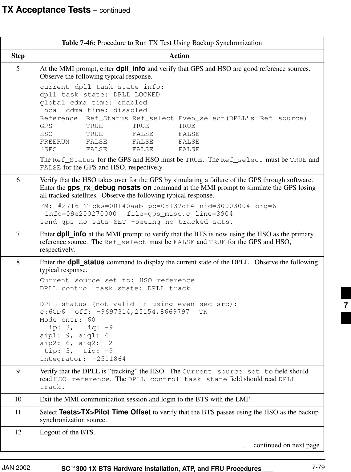
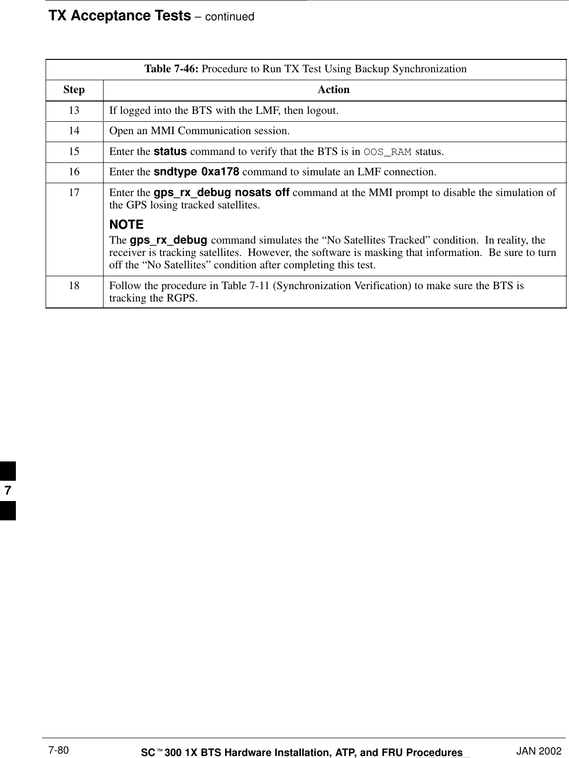
Table of Contents  – continuedDRAFTSCt300 1X BTS Hardware Installation, ATP, and FRU Procedures JAN 2002Procedure to Set Frame ID for Multi–Unit Logical BTS Configuration 7-31BTS Software 7-32. . . . . . . . . . . . . . . . . . . . . . . . . . . . . . . . . . . . . . . . . . . . . . . . . . . Objective 7-32. . . . . . . . . . . . . . . . . . . . . . . . . . . . . . . . . . . . . . . . . . . . . . . . Install the LMF Program and BTS Binaries 7-32. . . . . . . . . . . . . . . . . . . . . Create a Site–Specific BTS Directory 7-32. . . . . . . . . . . . . . . . . . . . . . . . . . Start the LMF and Login to the BTS 7-32. . . . . . . . . . . . . . . . . . . . . . . . . . . Update BTS Specific CDF File Device Load Version 7-33. . . . . . . . . . . . . Download/Enable MAWI 7-34. . . . . . . . . . . . . . . . . . . . . . . . . . . . . . . . . . . Configuration Data File (CDF) 7-35. . . . . . . . . . . . . . . . . . . . . . . . . . . . . . . System Status LED States 7-36. . . . . . . . . . . . . . . . . . . . . . . . . . . . . . . . . . . Verify and Set Span Line Settings 7-37. . . . . . . . . . . . . . . . . . . . . . . . . . . . . . . . . . . Objective 7-37. . . . . . . . . . . . . . . . . . . . . . . . . . . . . . . . . . . . . . . . . . . . . . . . Span Line Settings 7-37. . . . . . . . . . . . . . . . . . . . . . . . . . . . . . . . . . . . . . . . . Procedure to Verify and Set Span Line Settings 7-37. . . . . . . . . . . . . . . . . . SPAN_CONFIG Parameters 7-39. . . . . . . . . . . . . . . . . . . . . . . . . . . . . . . . . GPIB Addresses 7-40. . . . . . . . . . . . . . . . . . . . . . . . . . . . . . . . . . . . . . . . . . . . . . . . . Introduction 7-40. . . . . . . . . . . . . . . . . . . . . . . . . . . . . . . . . . . . . . . . . . . . . . Verify the Gigatronics 8541C Power Meter GPIB Address 7-40. . . . . . . . . Verify and Set Motorola CyberTest GPIB Address 7-41. . . . . . . . . . . . . . . . Verify and Set HP8935 Test Set GPIB Address 7-42. . . . . . . . . . . . . . . . . . Verify and Set the HP8921A and HP83236A/B GPIB Addresses 7-43. . . . Verify and Set Advantest R3465 GPIB Address 7-44. . . . . . . . . . . . . . . . . . RS232 GPIB Interface Box 7-45. . . . . . . . . . . . . . . . . . . . . . . . . . . . . . . . . . Verify and Set Advantest R3267  GPIB Address 7-45. . . . . . . . . . . . . . . . . Verify and Set Advantest R3562 Signal Generator GPIB Address 7-47. . . . Verify and Set Agilent E4406A Transmitter Tester GPIB Address 7-47. . . . Verify and Set Agilent E4432B Signal Generator GPIB Address 7-49. . . . . Test Equipment Calibration 7-51. . . . . . . . . . . . . . . . . . . . . . . . . . . . . . . . . . . . . . . . Background 7-51. . . . . . . . . . . . . . . . . . . . . . . . . . . . . . . . . . . . . . . . . . . . . . Procedure to Calibrate Test Equipment 7-52. . . . . . . . . . . . . . . . . . . . . . . . . Calibration Without the LMF 7-52. . . . . . . . . . . . . . . . . . . . . . . . . . . . . . . . Procedure to Calibrate R3465 Test Set 7-53. . . . . . . . . . . . . . . . . . . . . . . . . Procedure to Calibrate R3267 Test Set 7-53. . . . . . . . . . . . . . . . . . . . . . . . . Procedure to Calibrate Agilent E4406A 7-54. . . . . . . . . . . . . . . . . . . . . . . . Procedure to Setup Advantest R3465 Test Equipment 7-55. . . . . . . . . . . . . Procedure to Setup Advantest R3267 Test Equipment 7-56. . . . . . . . . . . . . Test Equipment Selection 7-57. . . . . . . . . . . . . . . . . . . . . . . . . . . . . . . . . . . . . . . . . . Objective 7-57. . . . . . . . . . . . . . . . . . . . . . . . . . . . . . . . . . . . . . . . . . . . . . . . Prerequisites 7-57. . . . . . . . . . . . . . . . . . . . . . . . . . . . . . . . . . . . . . . . . . . . . . Procedure to Select Test Equipment 7-57. . . . . . . . . . . . . . . . . . . . . . . . . . . Selecting Test Equipment Automatically or Manually 7-58. . . . . . . . . . . . . Procedure to Manually Select Test Equipment in a Serial Connection Tab 7-58. . . . . . . . . . . . . . . . . . . . . . . . . . . . . . . . . . . . . . Procedure to Automatically Select Test Equipment in a Serial Connection Tab 7-59. . . . . . . . . . . . . . . . . . . . . . . . . . . . . . . . . . . . . . Power Meter Calibration 7-60. . . . . . . . . . . . . . . . . . . . . . . . . . . . . . . . . . . . . . . . . . . 7
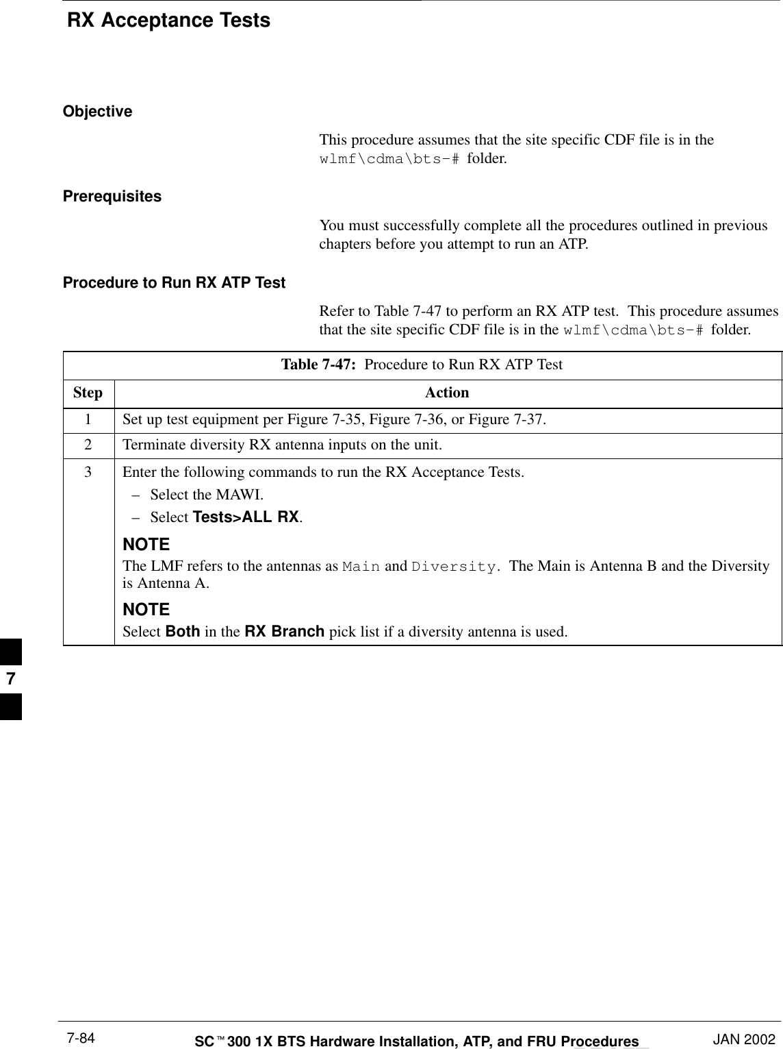
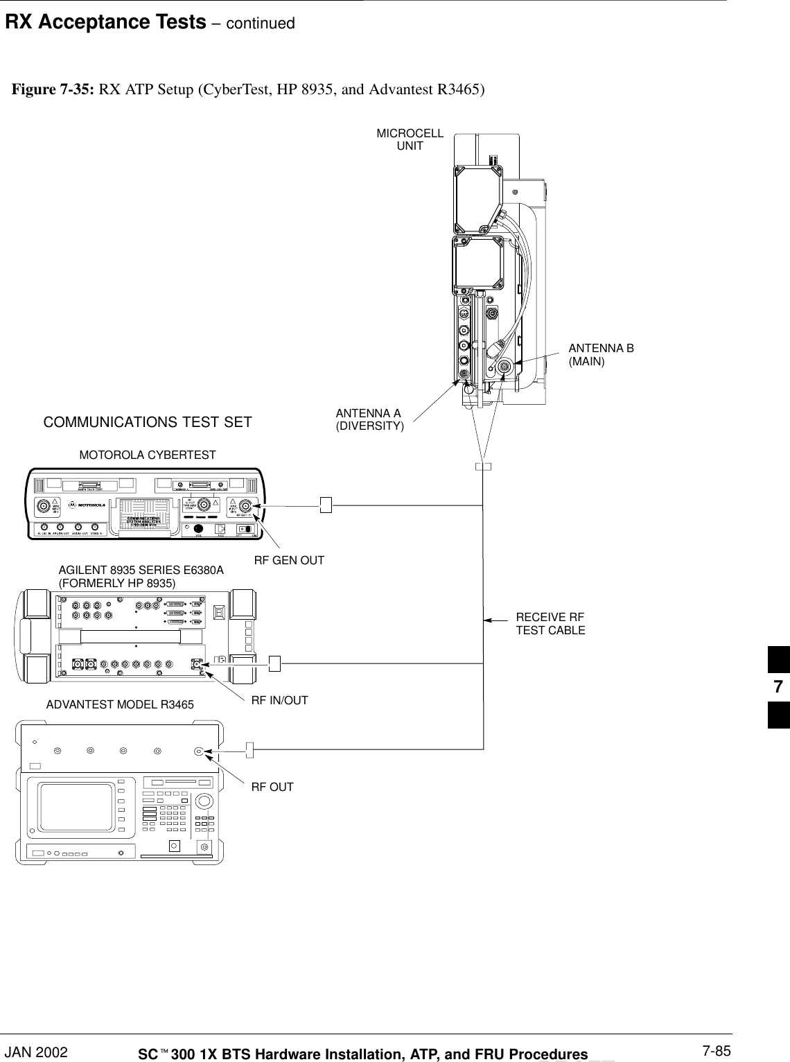
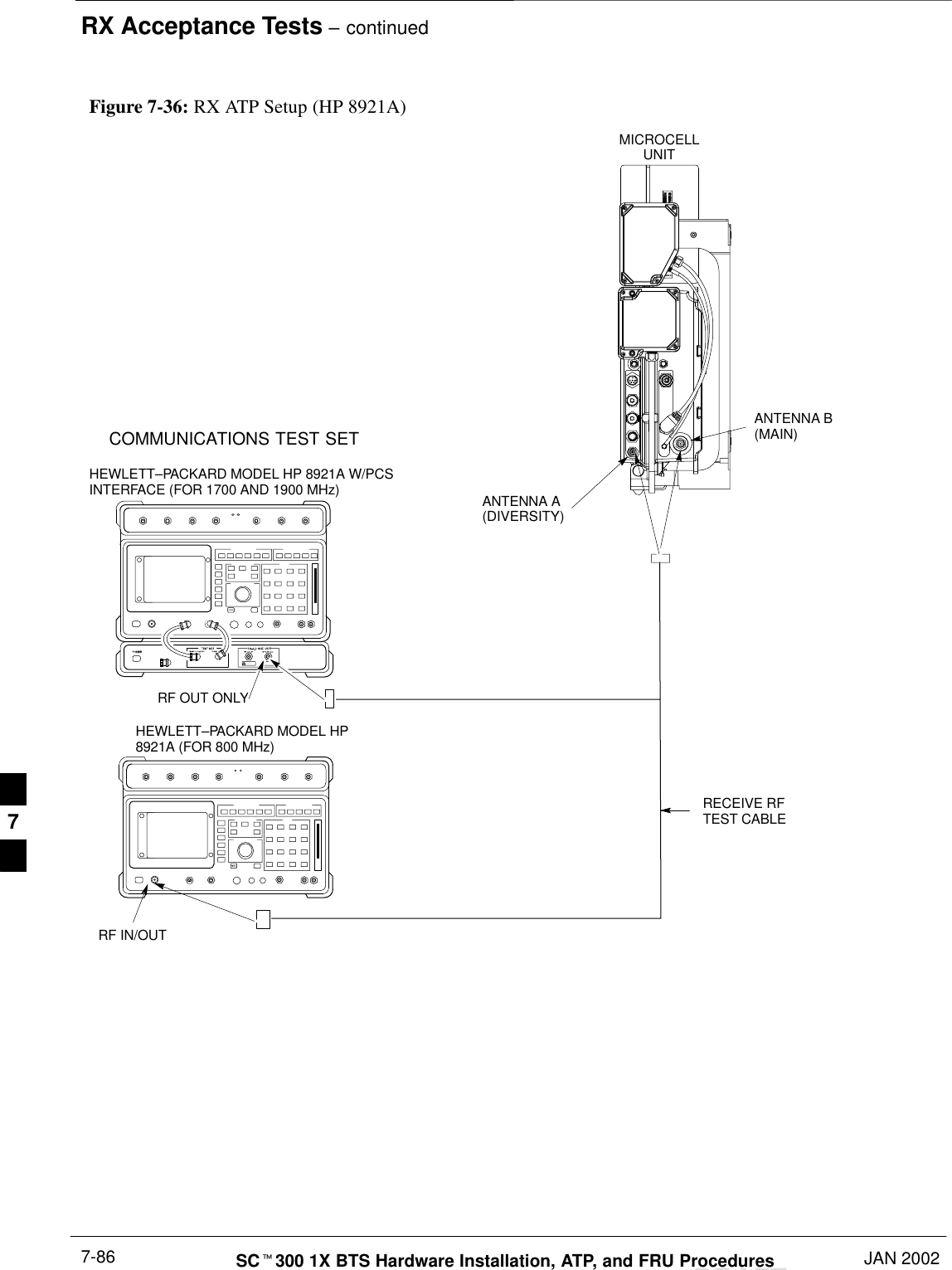
Table of Contents  – continuedJAN 2002 SCt300 1X BTS Hardware Installation, ATP, and FRU ProceduresDRAFTObjective 7-60. . . . . . . . . . . . . . . . . . . . . . . . . . . . . . . . . . . . . . . . . . . . . . . . Prerequisites 7-60. . . . . . . . . . . . . . . . . . . . . . . . . . . . . . . . . . . . . . . . . . . . . . Procedure to Calibrate the Power Meter 7-60. . . . . . . . . . . . . . . . . . . . . . . . Test Cable Calibration 7-61. . . . . . . . . . . . . . . . . . . . . . . . . . . . . . . . . . . . . . . . . . . . Background 7-61. . . . . . . . . . . . . . . . . . . . . . . . . . . . . . . . . . . . . . . . . . . . . . Purpose of Cable Calibration 7-61. . . . . . . . . . . . . . . . . . . . . . . . . . . . . . . . . Procedure to do an Automated Cable Calibration 7-62. . . . . . . . . . . . . . . . . Create CAL File 7-65. . . . . . . . . . . . . . . . . . . . . . . . . . . . . . . . . . . . . . . . . . . . . . . . . Objective 7-65. . . . . . . . . . . . . . . . . . . . . . . . . . . . . . . . . . . . . . . . . . . . . . . . Background 7-65. . . . . . . . . . . . . . . . . . . . . . . . . . . . . . . . . . . . . . . . . . . . . . Procedure to Create a CAL File 7-66. . . . . . . . . . . . . . . . . . . . . . . . . . . . . . . Acceptance Tests 7-67. . . . . . . . . . . . . . . . . . . . . . . . . . . . . . . . . . . . . . . . . . . . . . . . . Overview 7-67. . . . . . . . . . . . . . . . . . . . . . . . . . . . . . . . . . . . . . . . . . . . . . . . TX Test Objective 7-67. . . . . . . . . . . . . . . . . . . . . . . . . . . . . . . . . . . . . . . . . TX Tests 7-67. . . . . . . . . . . . . . . . . . . . . . . . . . . . . . . . . . . . . . . . . . . . . . . . . RX Test Objective 7-68. . . . . . . . . . . . . . . . . . . . . . . . . . . . . . . . . . . . . . . . . RX Tests 7-68. . . . . . . . . . . . . . . . . . . . . . . . . . . . . . . . . . . . . . . . . . . . . . . . . Subscriber Unit (SU) Test and Setup 7-69. . . . . . . . . . . . . . . . . . . . . . . . . . . . . . . . . Objective 7-69. . . . . . . . . . . . . . . . . . . . . . . . . . . . . . . . . . . . . . . . . . . . . . . . Background 7-69. . . . . . . . . . . . . . . . . . . . . . . . . . . . . . . . . . . . . . . . . . . . . . Procedure to Test and Verify SU 7-69. . . . . . . . . . . . . . . . . . . . . . . . . . . . . . Procedure to Program SU NAM Parameters 7-71. . . . . . . . . . . . . . . . . . . . . CDMA Operating Frequency Programming Information – North American Cellular Bands 7-73. . . . . . . . . . . . . . . . . . . . . . . . . . . . . . . . . . . . . . . . . . . . . . . . . . Objective 7-73. . . . . . . . . . . . . . . . . . . . . . . . . . . . . . . . . . . . . . . . . . . . . . . . 1900 MHz PCS Channels 7-73. . . . . . . . . . . . . . . . . . . . . . . . . . . . . . . . . . . Calculating 1900 MHz Center Frequencies 7-74. . . . . . . . . . . . . . . . . . . . . . 800 MHz CDMA Channels 7-76. . . . . . . . . . . . . . . . . . . . . . . . . . . . . . . . . . Calculating 800 MHz Center Frequencies 7-76. . . . . . . . . . . . . . . . . . . . . . . TX Acceptance Tests 7-78. . . . . . . . . . . . . . . . . . . . . . . . . . . . . . . . . . . . . . . . . . . . . Objective 7-78. . . . . . . . . . . . . . . . . . . . . . . . . . . . . . . . . . . . . . . . . . . . . . . . Prerequisites 7-78. . . . . . . . . . . . . . . . . . . . . . . . . . . . . . . . . . . . . . . . . . . . . . Procedure to Run TX ATP Test 7-78. . . . . . . . . . . . . . . . . . . . . . . . . . . . . . . Procedure to Run TX Tests Using Backup Synchronization (Sites Equipped With GPS) 7-78. . . . . . . . . . . . . . . . . . . . . . . . . . . . . . . . . . RX Acceptance Tests 7-84. . . . . . . . . . . . . . . . . . . . . . . . . . . . . . . . . . . . . . . . . . . . . Objective 7-84. . . . . . . . . . . . . . . . . . . . . . . . . . . . . . . . . . . . . . . . . . . . . . . . Prerequisites 7-84. . . . . . . . . . . . . . . . . . . . . . . . . . . . . . . . . . . . . . . . . . . . . . Procedure to Run RX ATP Test 7-84. . . . . . . . . . . . . . . . . . . . . . . . . . . . . . . Generate an ATP Report 7-88. . . . . . . . . . . . . . . . . . . . . . . . . . . . . . . . . . . . . . . . . . . Background 7-88. . . . . . . . . . . . . . . . . . . . . . . . . . . . . . . . . . . . . . . . . . . . . . ATP Report 7-88. . . . . . . . . . . . . . . . . . . . . . . . . . . . . . . . . . . . . . . . . . . . . . Procedure to Run ATP Report 7-88. . . . . . . . . . . . . . . . . . . . . . . . . . . . . . . . Copy LMF CAL File to CBSC 7-89. . . . . . . . . . . . . . . . . . . . . . . . . . . . . . . . . . . . . Objective 7-89. . . . . . . . . . . . . . . . . . . . . . . . . . . . . . . . . . . . . . . . . . . . . . . . 7
Table of Contents  – continuedDRAFTSCt300 1X BTS Hardware Installation, ATP, and FRU Procedures JAN 2002Background 7-89. . . . . . . . . . . . . . . . . . . . . . . . . . . . . . . . . . . . . . . . . . . . . . Procedure to Copy CAL Files from LMF to a Diskette 7-89. . . . . . . . . . . . Procedure to Copy CAL Files from Diskette to the CBSC 7-90. . . . . . . . . . Prepare to Leave the Site 7-91. . . . . . . . . . . . . . . . . . . . . . . . . . . . . . . . . . . . . . . . . . Remove External Test Equipment 7-91. . . . . . . . . . . . . . . . . . . . . . . . . . . . . Reset and Initialize Site Remotely 7-91. . . . . . . . . . . . . . . . . . . . . . . . . . . . . Bring BTS into Service with the CDMA LMF 7-91. . . . . . . . . . . . . . . . . . . Terminate LMF Session/Remove Terminal 7-92. . . . . . . . . . . . . . . . . . . . . . Replace Diagnostic Access Cover 7-93. . . . . . . . . . . . . . . . . . . . . . . . . . . . . Replace Solar Cover 7-93. . . . . . . . . . . . . . . . . . . . . . . . . . . . . . . . . . . . . . . 7
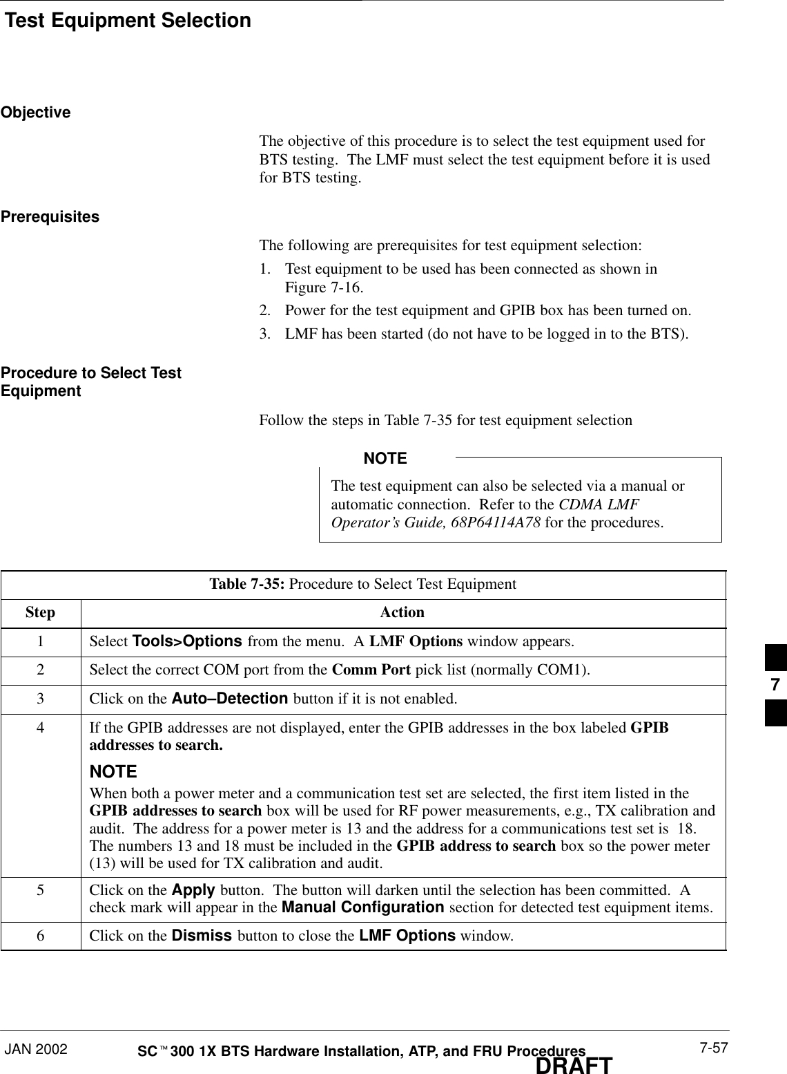
ATP OverviewJAN 2002 7-1SCt300 1X BTS Hardware Installation, ATP, and FRU ProceduresDRAFTOverviewThe purpose of this procedure is to outline the optimization and ATPafter a BTS installation. Calibration of the BTS is performed in thefactory and is not required.  The ATP is also performed in the factoryand is optional.All the procedures in this chapter are to be performed with the BTS outof service or under LMF control.  If necessary, refer to the “Shut Downand Restoring BTS Signaling” procedure in Chapter 7.For a complete listing of the required tools and equipment, refer to the“ATP Tools and Equipment” list in Chapter 1.You must run the ATP with LMF Software Release2.15.0.1.10 or higher.IMPORTANT*7
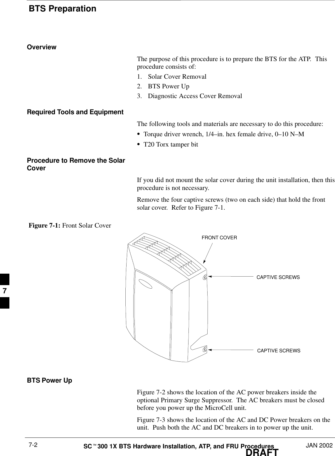
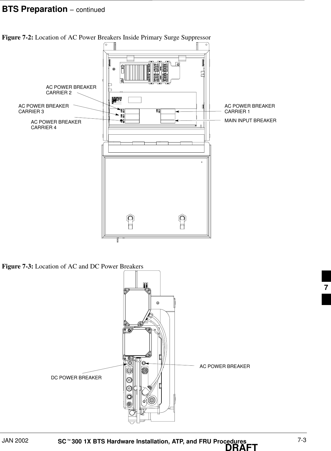
BTS PreparationDRAFTSCt300 1X BTS Hardware Installation, ATP, and FRU Procedures JAN 20027-2OverviewThe purpose of this procedure is to prepare the BTS for the ATP.  Thisprocedure consists of:1. Solar Cover Removal2. BTS Power Up3. Diagnostic Access Cover RemovalRequired Tools and EquipmentThe following tools and materials are necessary to do this procedure:STorque driver wrench, 1/4–in. hex female drive, 0–10 N–MST20 Torx tamper bitProcedure to Remove the SolarCoverIf you did not mount the solar cover during the unit installation, then thisprocedure is not necessary.Remove the four captive screws (two on each side) that hold the frontsolar cover.  Refer to Figure 7-1.Figure 7-1: Front Solar CoverFRONT COVERCAPTIVE SCREWSCAPTIVE SCREWSBTS Power UpFigure 7-2 shows the location of the AC power breakers inside theoptional Primary Surge Suppressor.  The AC breakers must be closedbefore you power up the MicroCell unit.Figure 7-3 shows the location of the AC and DC Power breakers on theunit.  Push both the AC and DC breakers in to power up the unit.7
BTS Preparation – continuedJAN 2002 7-3SCt300 1X BTS Hardware Installation, ATP, and FRU ProceduresDRAFTFigure 7-2: Location of AC Power Breakers Inside Primary Surge SuppressorAC POWER BREAKERCARRIER 1AC POWER BREAKERCARRIER 2AC POWER BREAKERCARRIER 3AC POWER BREAKERCARRIER 4MAIN INPUT BREAKERFigure 7-3: Location of AC and DC Power BreakersAC POWER BREAKERDC POWER BREAKER7
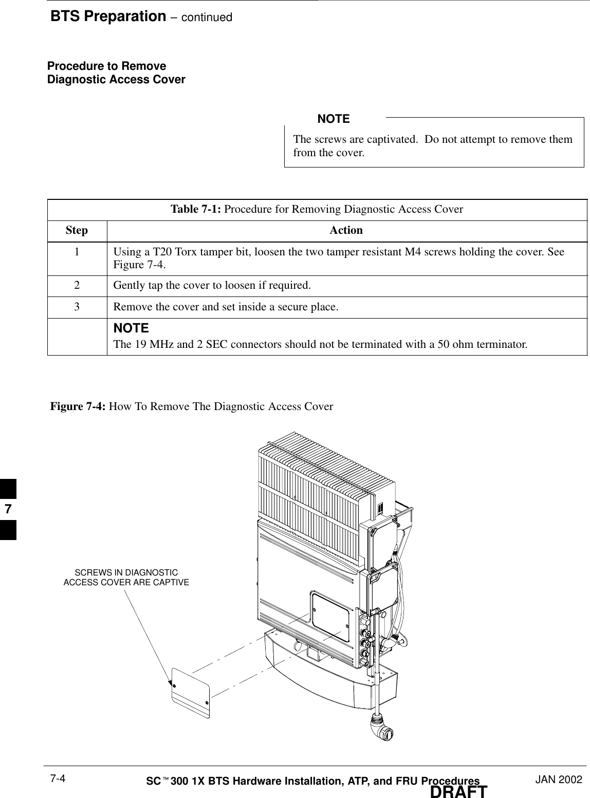
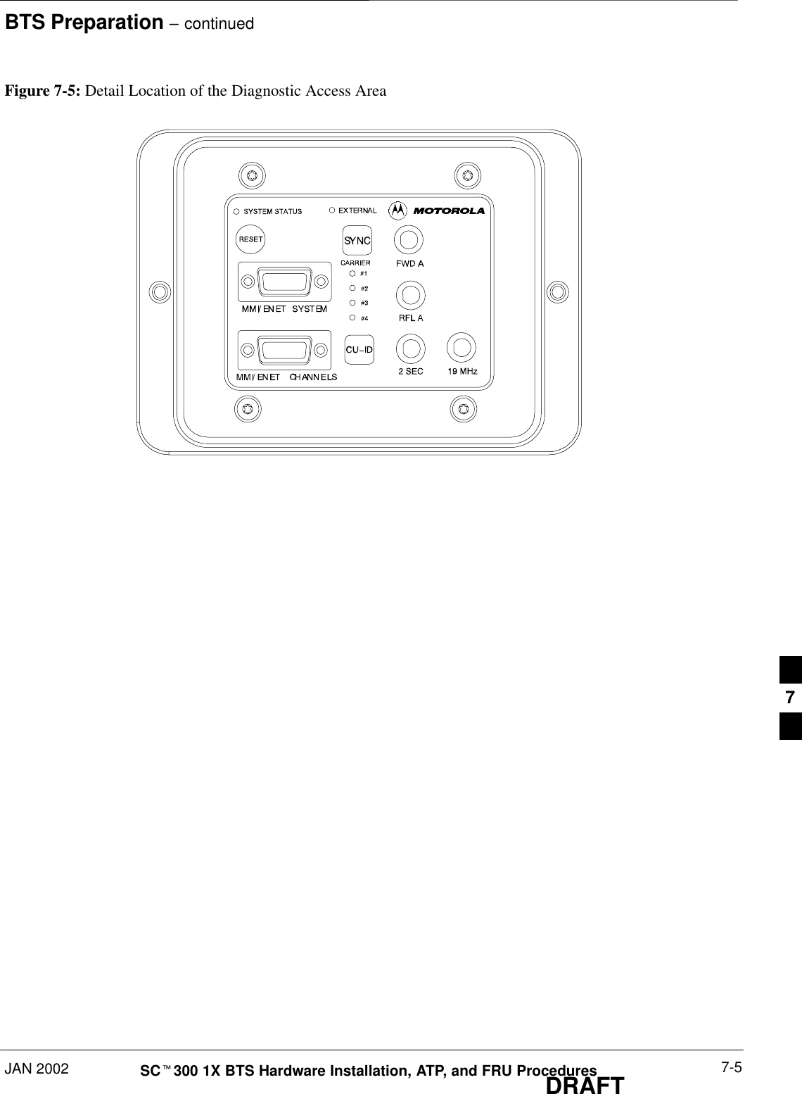
BTS Preparation – continuedDRAFTSCt300 1X BTS Hardware Installation, ATP, and FRU Procedures JAN 20027-4Procedure to RemoveDiagnostic Access CoverThe screws are captivated.  Do not attempt to remove themfrom the cover.NOTETable 7-1: Procedure for Removing Diagnostic Access CoverStep Action1Using a T20 Torx tamper bit, loosen the two tamper resistant M4 screws holding the cover. SeeFigure 7-4.2Gently tap the cover to loosen if required.3Remove the cover and set inside a secure place.NOTEThe 19 MHz and 2 SEC connectors should not be terminated with a 50 ohm terminator.Figure 7-4: How To Remove The Diagnostic Access CoverSCREWS IN DIAGNOSTICACCESS COVER ARE CAPTIVE7
BTS Preparation – continuedJAN 2002 7-5SCt300 1X BTS Hardware Installation, ATP, and FRU ProceduresDRAFTFigure 7-5: Detail Location of the Diagnostic Access Area7
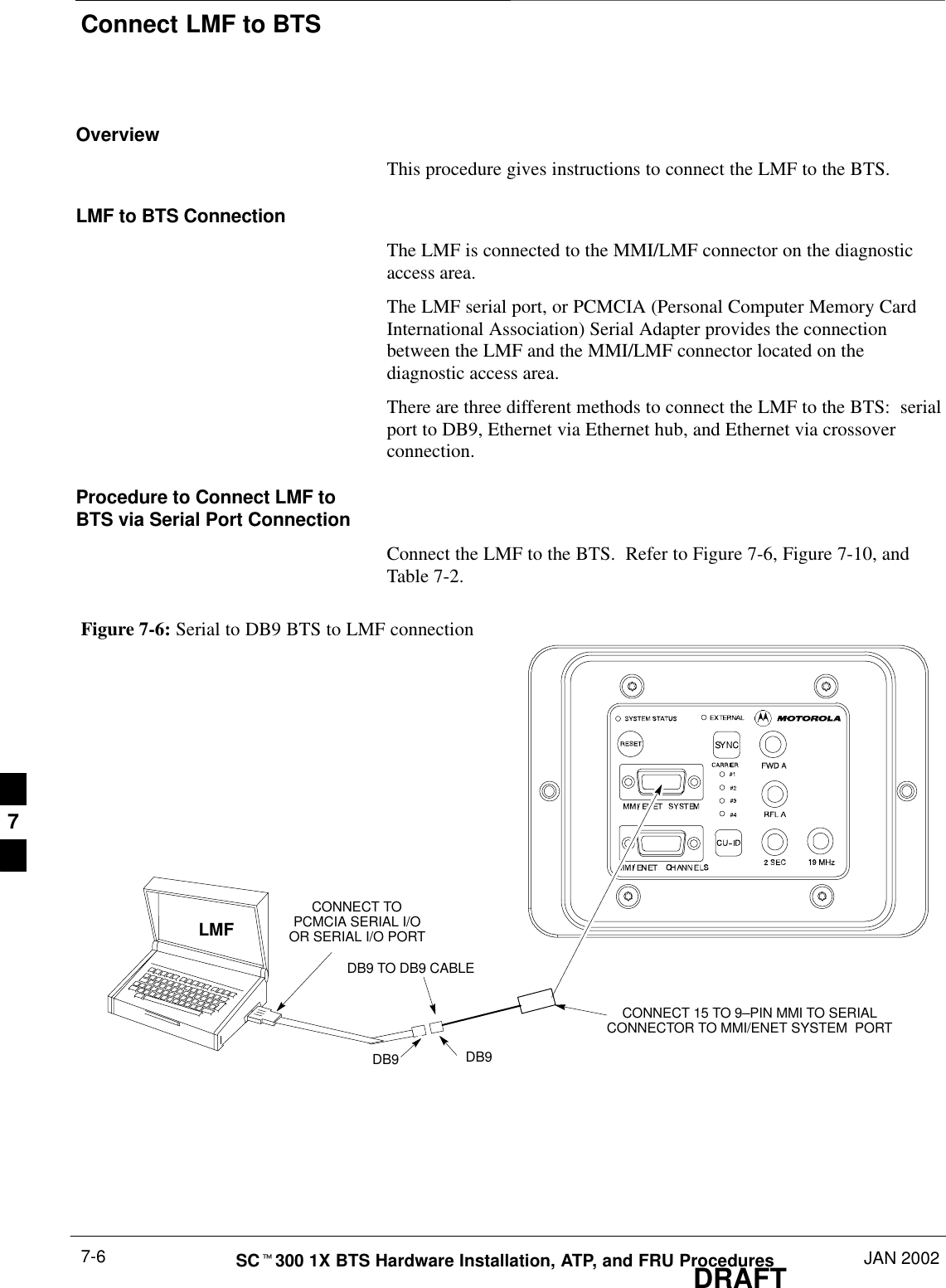
Connect LMF to BTSDRAFTSCt300 1X BTS Hardware Installation, ATP, and FRU Procedures JAN 20027-6OverviewThis procedure gives instructions to connect the LMF to the BTS.LMF to BTS ConnectionThe LMF is connected to the MMI/LMF connector on the diagnosticaccess area.The LMF serial port, or PCMCIA (Personal Computer Memory CardInternational Association) Serial Adapter provides the connectionbetween the LMF and the MMI/LMF connector located on thediagnostic access area.There are three different methods to connect the LMF to the BTS:  serialport to DB9, Ethernet via Ethernet hub, and Ethernet via crossoverconnection.Procedure to Connect LMF toBTS via Serial Port ConnectionConnect the LMF to the BTS.  Refer to Figure 7-6, Figure 7-10, andTable 7-2.Figure 7-6: Serial to DB9 BTS to LMF connectionDB9 DB9LMFDB9 TO DB9 CABLECONNECT 15 TO 9–PIN MMI TO SERIALCONNECTOR TO MMI/ENET SYSTEM  PORTCONNECT TOPCMCIA SERIAL I/OOR SERIAL I/O PORT7
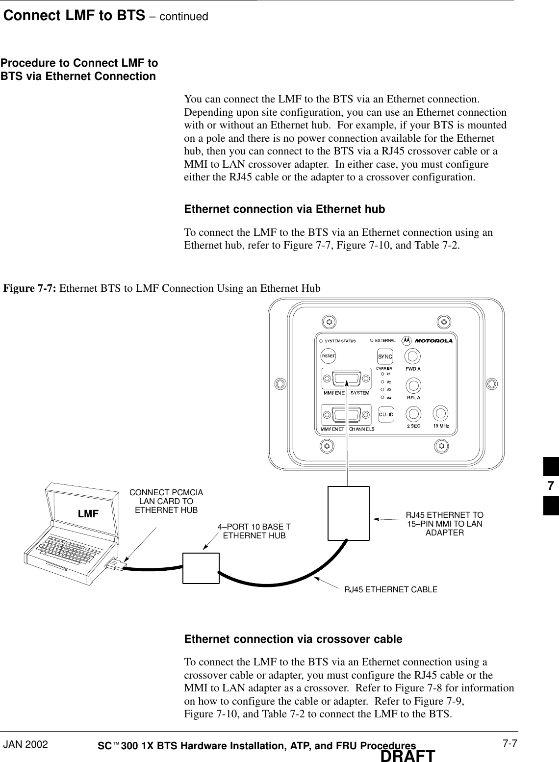
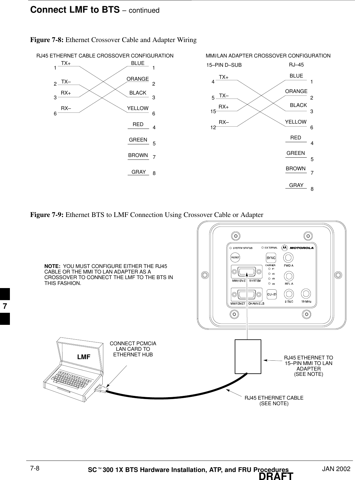
Connect LMF to BTS – continuedJAN 2002 7-7SCt300 1X BTS Hardware Installation, ATP, and FRU ProceduresDRAFTProcedure to Connect LMF toBTS via Ethernet ConnectionYou can connect the LMF to the BTS via an Ethernet connection.Depending upon site configuration, you can use an Ethernet connectionwith or without an Ethernet hub.  For example, if your BTS is mountedon a pole and there is no power connection available for the Ethernethub, then you can connect to the BTS via a RJ45 crossover cable or aMMI to LAN crossover adapter.  In either case, you must configureeither the RJ45 cable or the adapter to a crossover configuration.Ethernet connection via Ethernet hubTo connect the LMF to the BTS via an Ethernet connection using anEthernet hub, refer to Figure 7-7, Figure 7-10, and Table 7-2.Figure 7-7: Ethernet BTS to LMF Connection Using an Ethernet HubLMF4–PORT 10 BASE TETHERNET HUBCONNECT PCMCIALAN CARD TOETHERNET HUB RJ45 ETHERNET TO15–PIN MMI TO LANADAPTERRJ45 ETHERNET CABLEEthernet connection via crossover cableTo connect the LMF to the BTS via an Ethernet connection using acrossover cable or adapter, you must configure the RJ45 cable or theMMI to LAN adapter as a crossover.  Refer to Figure 7-8 for informationon how to configure the cable or adapter.  Refer to Figure 7-9,Figure 7-10, and Table 7-2 to connect the LMF to the BTS.7
Connect LMF to BTS – continuedDRAFTSCt300 1X BTS Hardware Installation, ATP, and FRU Procedures JAN 20027-8Figure 7-8: Ethernet Crossover Cable and Adapter Wiring RJ45 ETHERNET CABLE CROSSOVER CONFIGURATION12361236TX+TX–RX+RX– MMI/LAN ADAPTER CROSSOVER CONFIGURATION4515121236TX+TX–RX+RX–4578BLUEORANGEBLACKYELLOWREDGREENBROWNGRAY15–PIN D–SUB RJ–45REDGREENBROWNGRAY4578YELLOWBLACKORANGEBLUEFigure 7-9: Ethernet BTS to LMF Connection Using Crossover Cable or AdapterLMFCONNECT PCMCIALAN CARD TOETHERNET HUB RJ45 ETHERNET TO15–PIN MMI TO LANADAPTER(SEE NOTE)RJ45 ETHERNET CABLE(SEE NOTE)NOTE:  YOU MUST CONFIGURE EITHER THE RJ45CABLE OR THE MMI TO LAN ADAPTER AS ACROSSOVER TO CONNECT THE LMF TO THE BTS INTHIS FASHION.7
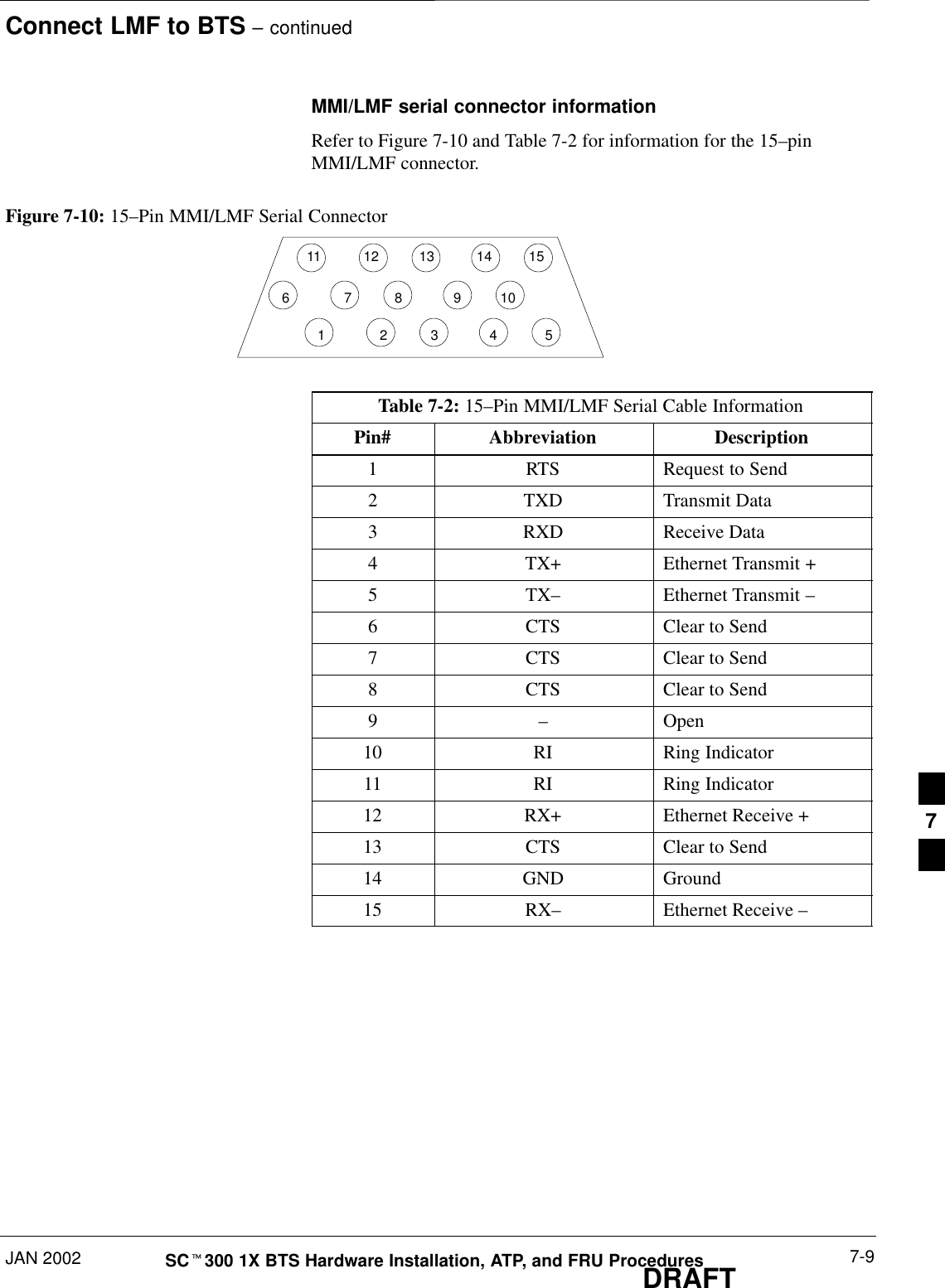
Connect LMF to BTS – continuedJAN 2002 7-9SCt300 1X BTS Hardware Installation, ATP, and FRU ProceduresDRAFTMMI/LMF serial connector informationRefer to Figure 7-10 and Table 7-2 for information for the 15–pinMMI/LMF connector.Figure 7-10: 15–Pin MMI/LMF Serial Connector11 12 13 14 1567891012345Table 7-2: 15–Pin MMI/LMF Serial Cable InformationPin# Abbreviation Description1RTS Request to Send2 TXD Transmit Data3 RXD Receive Data4 TX+ Ethernet Transmit +5 TX–Ethernet Transmit –6 CTS Clear to Send7 CTS Clear to Send8 CTS Clear to Send9–Open10 RI Ring Indicator11 RI Ring Indicator12 RX+ Ethernet Receive +13 CTS Clear to Send14 GND Ground15 RX–Ethernet Receive –7
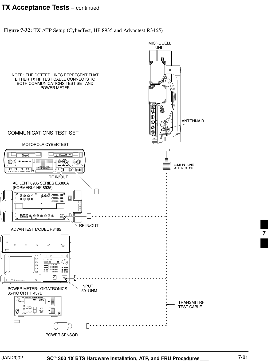
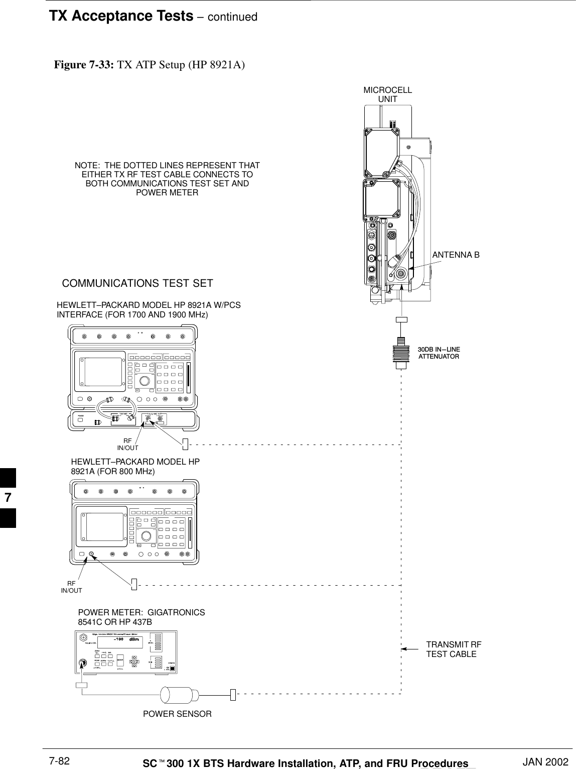
Connect Test Equipment to BTSDRAFTSCt300 1X BTS Hardware Installation, ATP, and FRU Procedures JAN 20027-10OverviewThe following test equipment setup applies to the BTS Acceptance TestProcedure (ATP).The SCt300 BTS supports the following test sets for IS95 A/B testing:1. Advantest R3465 with R3561 Signal Generator.2. Motorola CyberTest3. HP 8921A (for 800 MHz testing only)4. Aglient 8935 Series E6380A (formally HP8935)The 1X SCt300 BTS supports the following test sets for CDMA20001X testing:1. Advantest R3267 with R3562 Signal Generator2. Agilent E4406A with E4432B Signal GeneratorIf you are not going to perform the ATP, then proceed tothe “Creating a Named HyperTerminal Connection forMMI Communication” procedure in this chapter.NOTEEquipment warm-upWarm-up BTS equipment site for a minimum of 60minutes prior to the BTS ATP. This assures BTS sitestability and contributes to test accuracy.(Time spent running initial power–up,  hardware/firmwareaudit, and BTS download counts as warm–up time).IMPORTANT*Warm-up test equipment for a minimum of 60 minutesprior to their use in the BTS ATP. This assures maximumequipment measurement accuracy and consistency duringtesting.IMPORTANT*All test equipment is controlled by the LMF via a Serial Cable/GPIBbus. The LMF expects each piece of test equipment to have a factory-setGPIB address. If there is a communications problem between the LMFand any piece of test equipment, you should verify that the GPIBaddresses have been set correctly.7
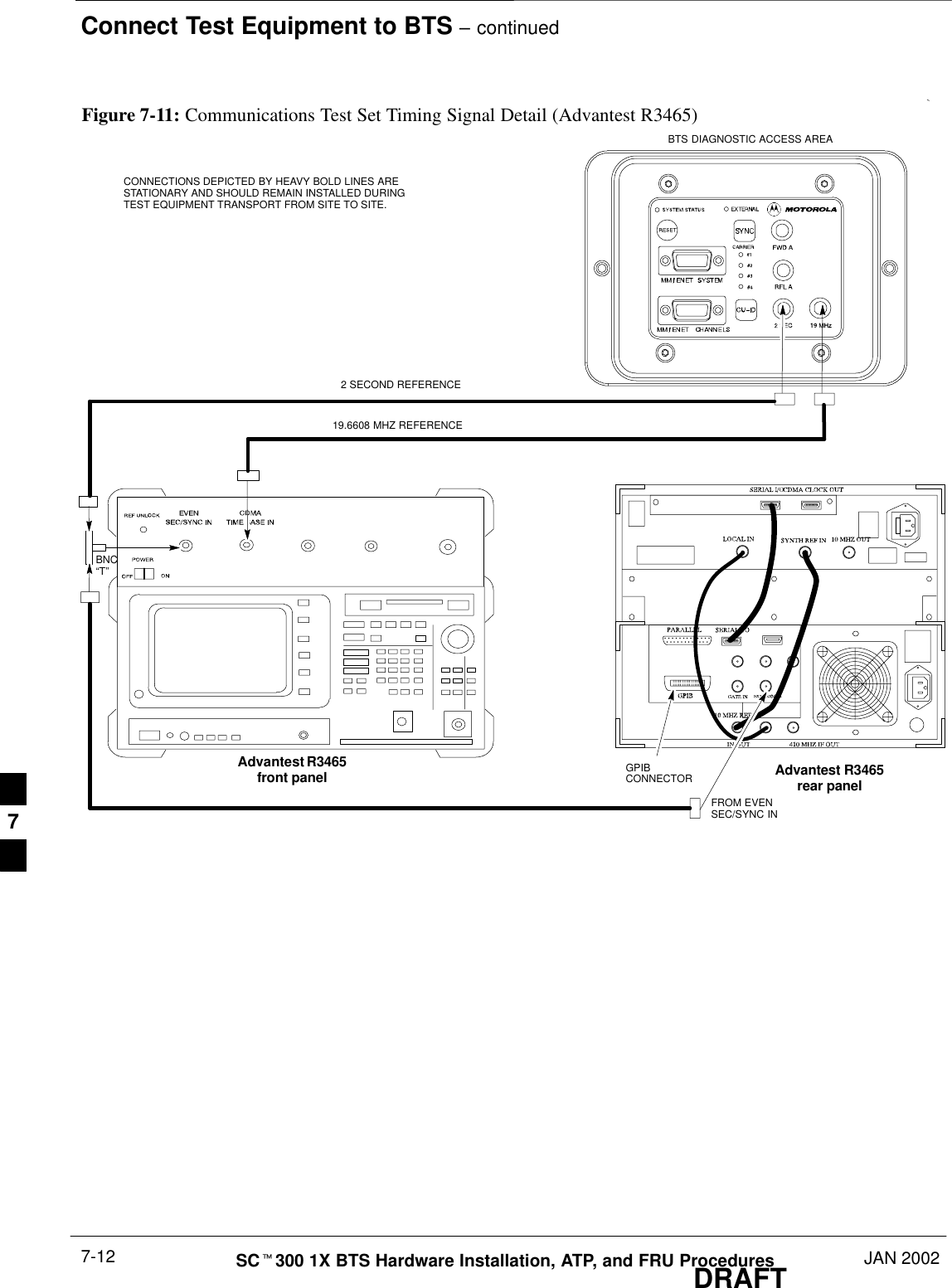
Connect Test Equipment to BTS – continuedJAN 2002 7-11SCt300 1X BTS Hardware Installation, ATP, and FRU ProceduresDRAFTIn the following procedure and illustrations, typical DIPswitch positions and/or configurations are shown. Ifrequired, refer to the test equipment OEM user manuals foradditional information.NOTEProcedure to ConnectAdvantest R3465 to BTSFollow the procedure in Table 7-3 to connect the Advantest R3465 to theBTS.  Refer to Figure 7-11.Table 7-3: Connecting Advantest R3465 to the BTSStep Action1Connect an SMA/BNC coax cable between the following points:–BNC on the Advantest CDMA TIMEBASE IN port.–SMA on the 19 MHz port on the diagnostic access area of the BTS.2Connect an SMA/BNC cable between the following points:–BNC to one end of the BNC “T.”–SMA on the 2 Sec port on the diagnostic access area of the BTS.3Connect a BNC/BNC cable between the following points:–BNC to one end of the BNC “T.”–BNC to the EXT TRIG port on the rear panel of the Advantest R3465.4Connect the BNC “T” to the EVEN SEC/SYNC IN port of the Advantest R356IL.5Verify the R3561 and R3465 rear panel connections are in place (These are common connections andshould already be installed):–Serial cable between 3465A rear panel SERIAL I/O port and R3561 SERIAL I/O port.–SMA cable between 3465A rear panel 1ST LO OUT port and R3561 LOCAL IN port.7
Connect Test Equipment to BTS – continuedDRAFTSCt300 1X BTS Hardware Installation, ATP, and FRU Procedures JAN 20027-12Advantest R3465front panel Advantest R3465rear panelBNC“T”CONNECTIONS DEPICTED BY HEAVY BOLD LINES ARESTATIONARY AND SHOULD REMAIN INSTALLED DURINGTEST EQUIPMENT TRANSPORT FROM SITE TO SITE.19.6608 MHZ REFERENCE2 SECOND REFERENCEGPIBCONNECTORFROM EVENSEC/SYNC INFigure 7-11: Communications Test Set Timing Signal Detail (Advantest R3465)BTS DIAGNOSTIC ACCESS AREA7
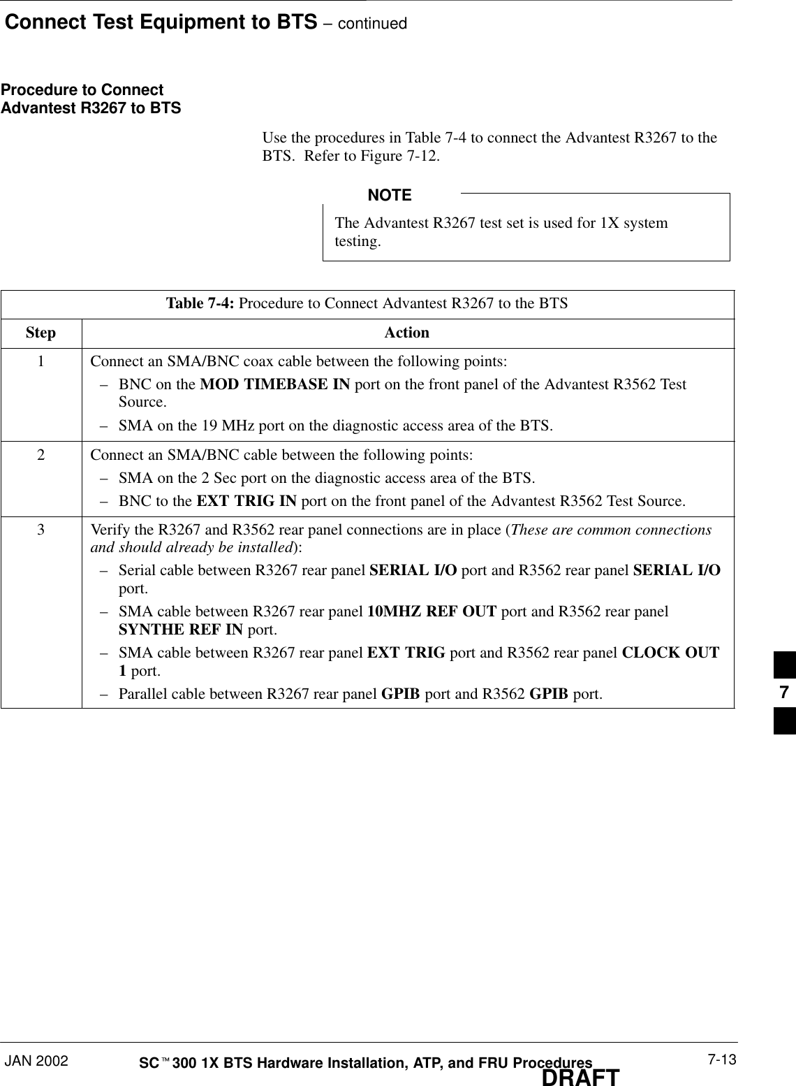
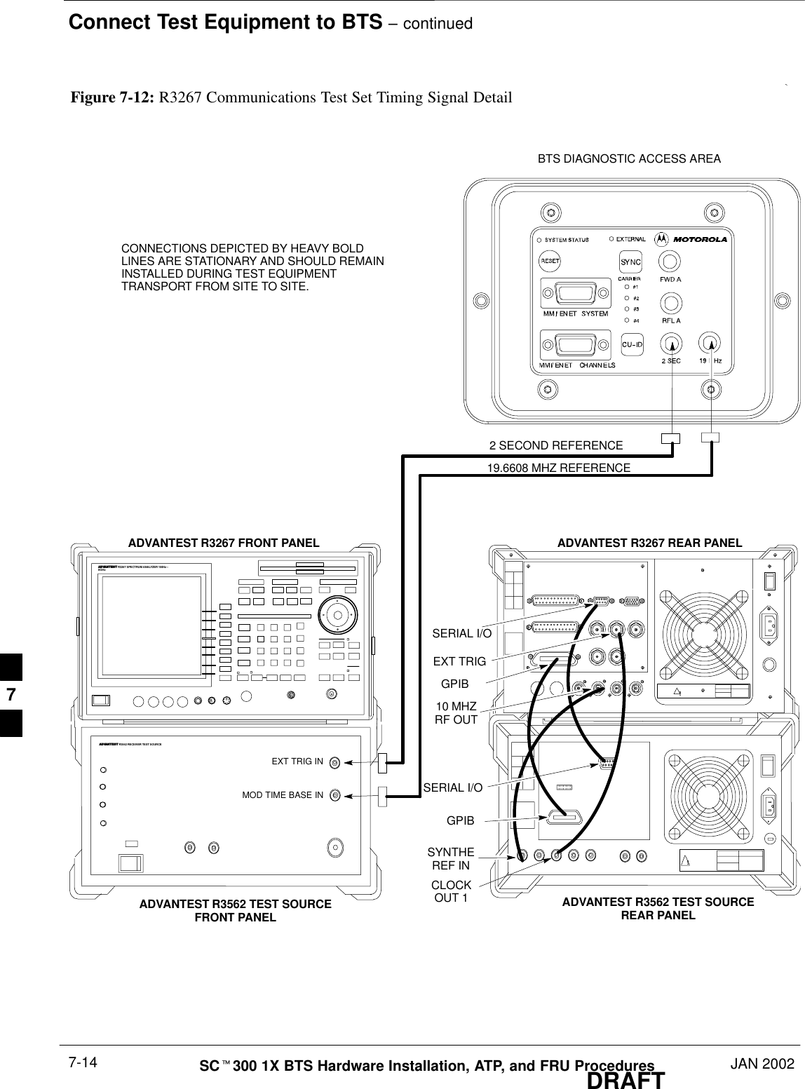
Connect Test Equipment to BTS – continuedJAN 2002 7-13SCt300 1X BTS Hardware Installation, ATP, and FRU ProceduresDRAFTProcedure to ConnectAdvantest R3267 to BTSUse the procedures in Table 7-4 to connect the Advantest R3267 to theBTS.  Refer to Figure 7-12.The Advantest R3267 test set is used for 1X systemtesting.NOTETable 7-4: Procedure to Connect Advantest R3267 to the BTSStep Action1Connect an SMA/BNC coax cable between the following points:–BNC on the MOD TIMEBASE IN port on the front panel of the Advantest R3562 TestSource.–SMA on the 19 MHz port on the diagnostic access area of the BTS.2Connect an SMA/BNC cable between the following points:–SMA on the 2 Sec port on the diagnostic access area of the BTS.–BNC to the EXT TRIG IN port on the front panel of the Advantest R3562 Test Source.3Verify the R3267 and R3562 rear panel connections are in place (These are common connectionsand should already be installed):–Serial cable between R3267 rear panel SERIAL I/O port and R3562 rear panel SERIAL I/Oport.–SMA cable between R3267 rear panel 10MHZ REF OUT port and R3562 rear panelSYNTHE REF IN port.–SMA cable between R3267 rear panel EXT TRIG port and R3562 rear panel CLOCK OUT1 port.–Parallel cable between R3267 rear panel GPIB port and R3562 GPIB port. 7
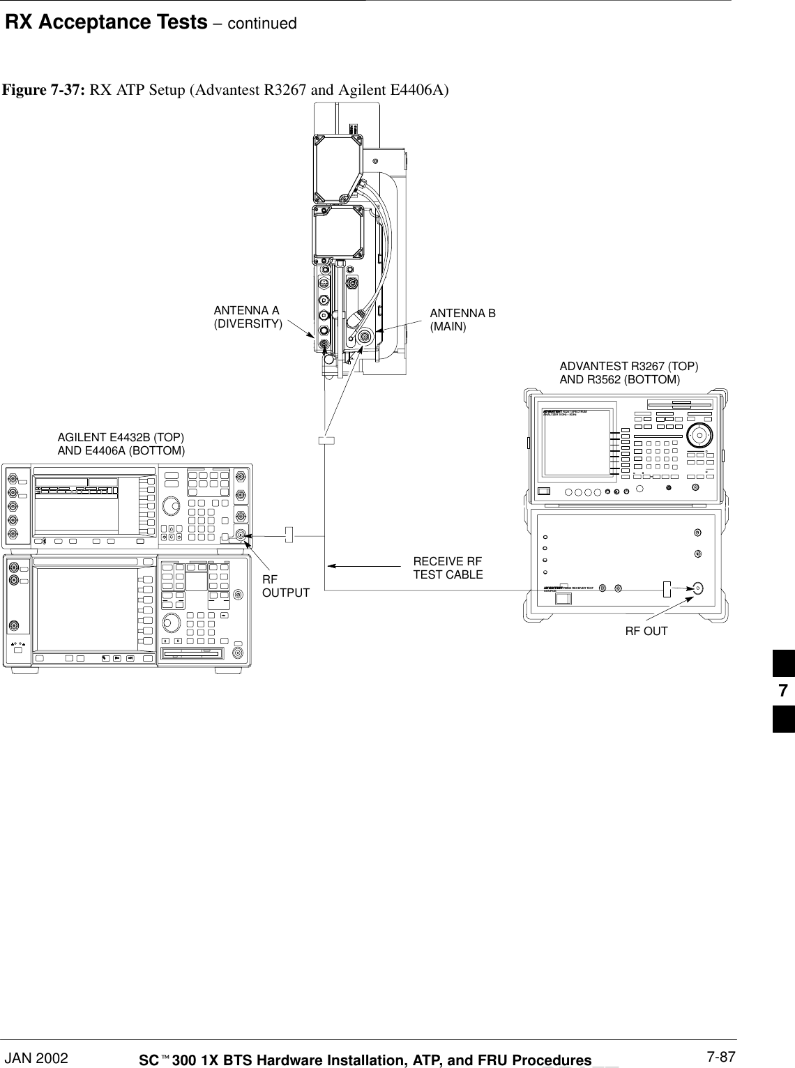
Connect Test Equipment to BTS – continuedDRAFTSCt300 1X BTS Hardware Installation, ATP, and FRU Procedures JAN 20027-14ADVANTEST R3267 FRONT PANEL ADVANTEST R3267 REAR PANELCONNECTIONS DEPICTED BY HEAVY BOLDLINES ARE STATIONARY AND SHOULD REMAININSTALLED DURING TEST EQUIPMENTTRANSPORT FROM SITE TO SITE.19.6608 MHZ REFERENCE2 SECOND REFERENCEFigure 7-12: R3267 Communications Test Set Timing Signal DetailBTS DIAGNOSTIC ACCESS AREAADVANTEST R3267 SPECTRUM ANALYZER 100Hz –8GHzADVANTEST R3562 RECEIVER TEST SOURCE!!ADVANTEST R3562 TEST SOURCEFRONT PANELADVANTEST R3562 TEST SOURCEREAR PANELEXT TRIG INMOD TIME BASE INSYNTHEREF IN10 MHZRF OUTSERIAL I/OSERIAL I/OEXT TRIGCLOCKOUT 1GPIBGPIB7
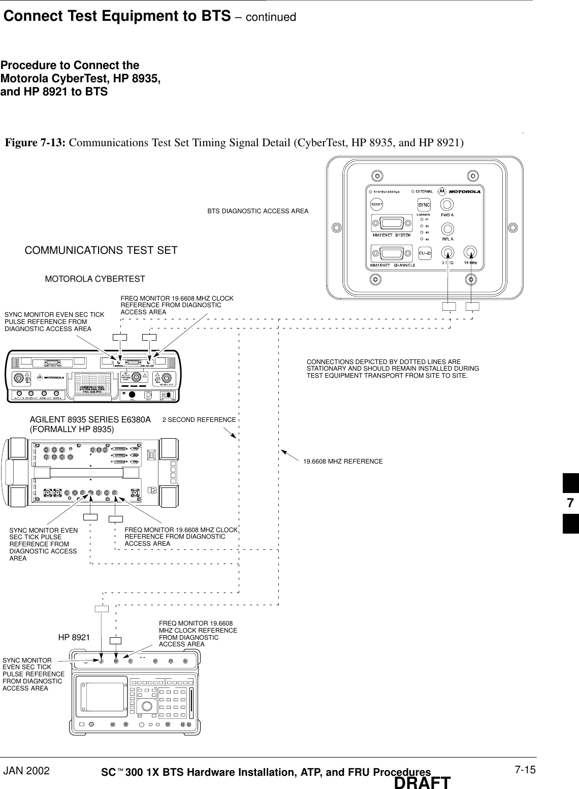
Connect Test Equipment to BTS – continuedJAN 2002 7-15SCt300 1X BTS Hardware Installation, ATP, and FRU ProceduresDRAFTProcedure to Connect theMotorola CyberTest, HP 8935,and HP 8921 to BTSCONNECTIONS DEPICTED BY DOTTED LINES ARESTATIONARY AND SHOULD REMAIN INSTALLED DURINGTEST EQUIPMENT TRANSPORT FROM SITE TO SITE.19.6608 MHZ REFERENCE2 SECOND REFERENCEFigure 7-13: Communications Test Set Timing Signal Detail (CyberTest, HP 8935, and HP 8921)BTS DIAGNOSTIC ACCESS AREAMOTOROLA CYBERTESTAGILENT 8935 SERIES E6380A(FORMALLY HP 8935)HP 8921COMMUNICATIONS TEST SETFREQ MONITOR 19.6608MHZ CLOCK REFERENCEFROM DIAGNOSTICACCESS AREAFREQ MONITOR 19.6608 MHZ CLOCKREFERENCE FROM DIAGNOSTICACCESS AREAFREQ MONITOR 19.6608 MHZ CLOCKREFERENCE FROM DIAGNOSTICACCESS AREASYNC MONITOR EVEN SEC TICKPULSE REFERENCE FROMDIAGNOSTIC ACCESS AREASYNC MONITOR EVENSEC TICK PULSEREFERENCE FROMDIAGNOSTIC ACCESSAREASYNC MONITOREVEN SEC TICKPULSE REFERENCEFROM DIAGNOSTICACCESS AREA7
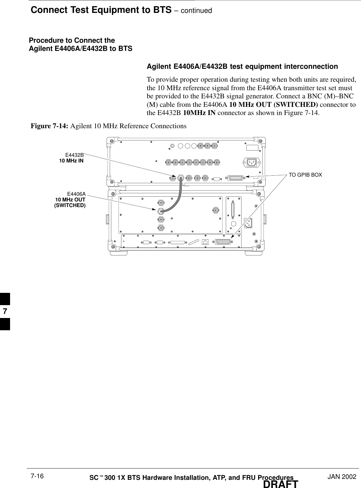
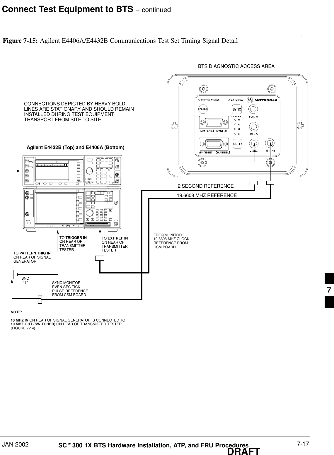
Connect Test Equipment to BTS – continuedDRAFTSCt300 1X BTS Hardware Installation, ATP, and FRU Procedures JAN 20027-16Procedure to Connect theAgilent E4406A/E4432B to BTSAgilent E4406A/E4432B test equipment interconnectionTo provide proper operation during testing when both units are required,the 10 MHz reference signal from the E4406A transmitter test set mustbe provided to the E4432B signal generator. Connect a BNC (M)–BNC(M) cable from the E4406A 10 MHz OUT (SWITCHED) connector tothe E4432B 10MHz IN connector as shown in Figure 7-14.Figure 7-14: Agilent 10 MHz Reference ConnectionsE4406A10 MHz OUT(SWITCHED)E4432B10 MHz INTO GPIB BOX7
Connect Test Equipment to BTS – continuedJAN 2002 7-17SCt300 1X BTS Hardware Installation, ATP, and FRU ProceduresDRAFTCONNECTIONS DEPICTED BY HEAVY BOLDLINES ARE STATIONARY AND SHOULD REMAININSTALLED DURING TEST EQUIPMENTTRANSPORT FROM SITE TO SITE.19.6608 MHZ REFERENCE2 SECOND REFERENCEFigure 7-15: Agilent E4406A/E4432B Communications Test Set Timing Signal DetailBTS DIAGNOSTIC ACCESS AREAAgilent E4432B (Top) and E4406A (Bottom)FREQ MONITOR19.6608 MHZ CLOCKREFERENCE FROMCSM BOARDSYNC MONITOREVEN SEC TICKPULSE REFERENCEFROM CSM BOARDBNC“T”TO TRIGGER INON REAR OFTRANSMITTERTESTERTO PATTERN TRIG INON REAR OF SIGNALGENERATORTO EXT REF IN ON REAR OFTRANSMITTERTESTER NOTE:10 MHZ IN ON REAR OF SIGNAL GENERATOR IS CONNECTED TO10 MHZ OUT (SWITCHED) ON REAR OF TRANSMITTER TESTER(FIGURE 7-14).7
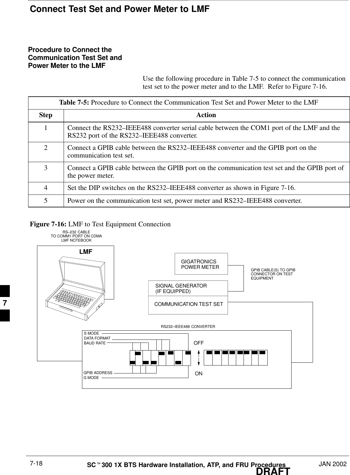
Connect Test Set and Power Meter to LMFDRAFTSCt300 1X BTS Hardware Installation, ATP, and FRU Procedures JAN 20027-18Procedure to Connect theCommunication Test Set andPower Meter to the LMFUse the following procedure in Table 7-5 to connect the communicationtest set to the power meter and to the LMF.  Refer to Figure 7-16.Table 7-5: Procedure to Connect the Communication Test Set and Power Meter to the LMFStep Action1Connect the RS232–IEEE488 converter serial cable between the COM1 port of the LMF and theRS232 port of the RS232–IEEE488 converter.2Connect a GPIB cable between the RS232–IEEE488 converter and the GPIB port on thecommunication test set.3Connect a GPIB cable between the GPIB port on the communication test set and the GPIB port ofthe power meter.4Set the DIP switches on the RS232–IEEE488 converter as shown in Figure 7-16.5Power on the communication test set, power meter and RS232–IEEE488 converter.Figure 7-16: LMF to Test Equipment ConnectionLMFOFFONS MODEDATA FORMATBAUD RATEGPIB ADDRESSG MODERS232–IEEE488 CONVERTERGIGATRONICSPOWER METERSIGNAL GENERATOR(IF EQUIPPED)COMMUNICATION TEST SETGPIB CABLE(S) TO GPIBCONNECTOR ON TESTEQUIPMENTRS–232 CABLETO COMM1 PORT ON CDMALMF NOTEBOOK7
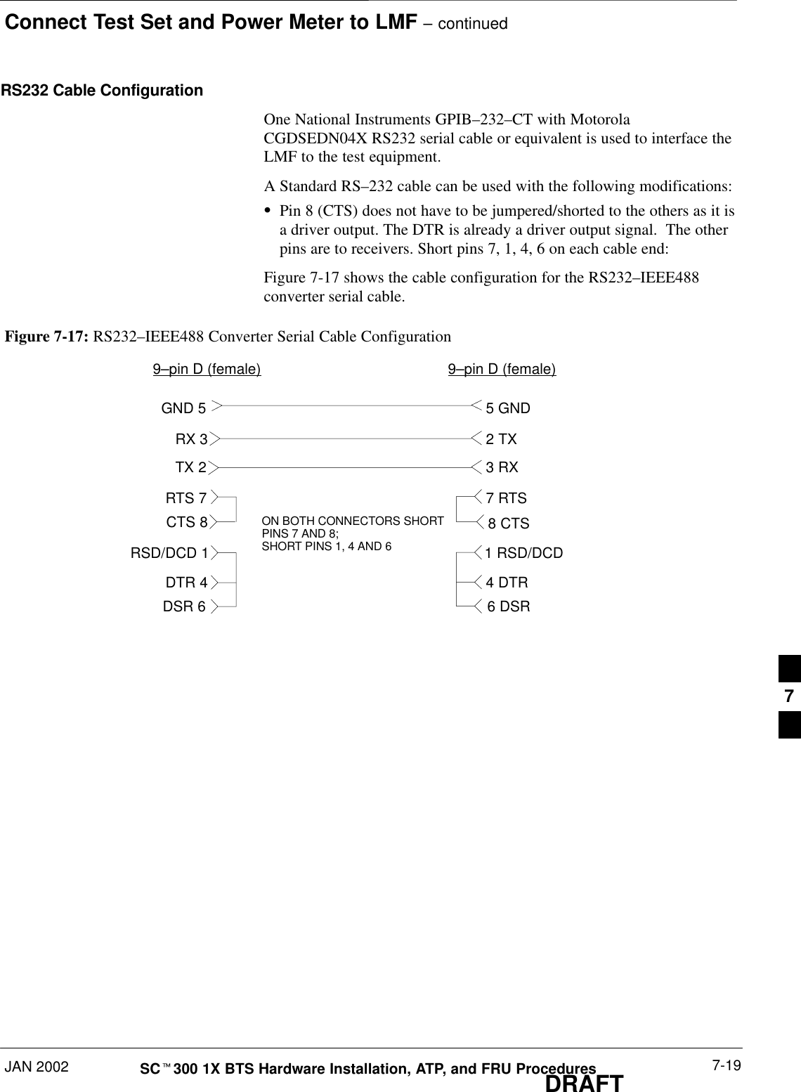
Connect Test Set and Power Meter to LMF – continuedJAN 2002 7-19SCt300 1X BTS Hardware Installation, ATP, and FRU ProceduresDRAFTRS232 Cable ConfigurationOne National Instruments GPIB–232–CT with MotorolaCGDSEDN04X RS232 serial cable or equivalent is used to interface theLMF to the test equipment.A Standard RS–232 cable can be used with the following modifications:SPin 8 (CTS) does not have to be jumpered/shorted to the others as it isa driver output. The DTR is already a driver output signal.  The otherpins are to receivers. Short pins 7, 1, 4, 6 on each cable end:Figure 7-17 shows the cable configuration for the RS232–IEEE488converter serial cable.9–pin D (female) 9–pin D (female)GND 5 5 GNDRX 33 RXTX 22 TXRTS 7 7 RTSRSD/DCD 1 1 RSD/DCDDTR 4 4 DTRDSR 6 6 DSRFigure 7-17: RS232–IEEE488 Converter Serial Cable ConfigurationCTS 8 8 CTSON BOTH CONNECTORS SHORTPINS 7 AND 8;SHORT PINS 1, 4 AND 67
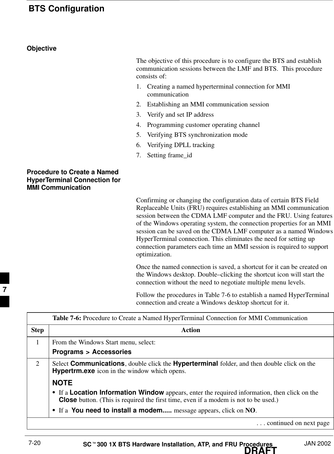
BTS ConfigurationDRAFTSCt300 1X BTS Hardware Installation, ATP, and FRU Procedures JAN 20027-20ObjectiveThe objective of this procedure is to configure the BTS and establishcommunication sessions between the LMF and BTS.  This procedureconsists of:1. Creating a named hyperterminal connection for MMIcommunication2. Establishing an MMI communication session3. Verify and set IP address4. Programming customer operating channel5. Verifying BTS synchronization mode6. Verifying DPLL tracking7. Setting frame_idProcedure to Create a NamedHyperTerminal Connection forMMI CommunicationConfirming or changing the configuration data of certain BTS FieldReplaceable Units (FRU) requires establishing an MMI communicationsession between the CDMA LMF computer and the FRU. Using featuresof the Windows operating system, the connection properties for an MMIsession can be saved on the CDMA LMF computer as a named WindowsHyperTerminal connection. This eliminates the need for setting upconnection parameters each time an MMI session is required to supportoptimization.Once the named connection is saved, a shortcut for it can be created onthe Windows desktop. Double–clicking the shortcut icon will start theconnection without the need to negotiate multiple menu levels.Follow the procedures in Table 7-6 to establish a named HyperTerminalconnection and create a Windows desktop shortcut for it.Table 7-6: Procedure to Create a Named HyperTerminal Connection for MMI CommunicationStep Action1From the Windows Start menu, select:Programs > Accessories2 Select Communications, double click the Hyperterminal folder, and then double click on theHypertrm.exe icon in the window which opens.NOTESIf a Location Information Window appears, enter the required information, then click on theClose button. (This is required the first time, even if a modem is not to be used.)SIf a  You need to install a modem..... message appears, click on NO. . . . continued on next page7
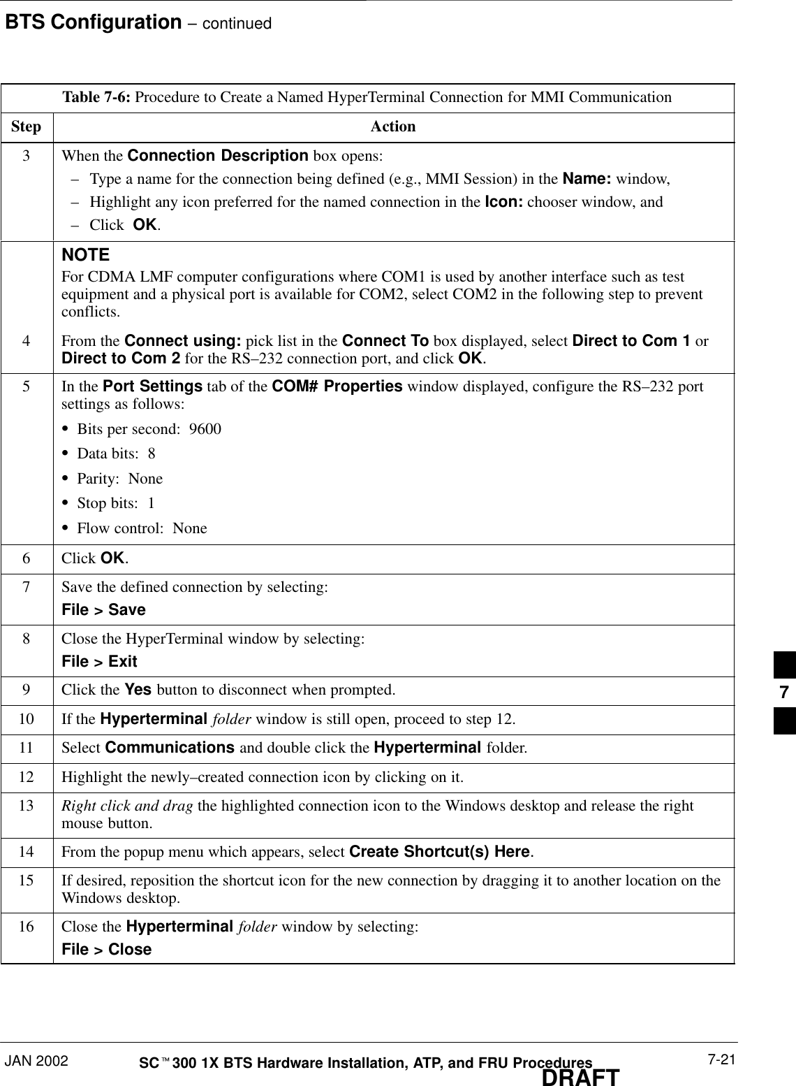
BTS Configuration – continuedJAN 2002 7-21SCt300 1X BTS Hardware Installation, ATP, and FRU ProceduresDRAFTTable 7-6: Procedure to Create a Named HyperTerminal Connection for MMI CommunicationStep Action3When the Connection Description box opens:–Type a name for the connection being defined (e.g., MMI Session) in the Name: window,–Highlight any icon preferred for the named connection in the Icon: chooser window, and–Click  OK.NOTEFor CDMA LMF computer configurations where COM1 is used by another interface such as testequipment and a physical port is available for COM2, select COM2 in the following step to preventconflicts.4From the Connect using: pick list in the Connect To box displayed, select Direct to Com 1 orDirect to Com 2 for the RS–232 connection port, and click OK.5In the Port Settings tab of the COM# Properties window displayed, configure the RS–232 portsettings as follows:SBits per second:  9600SData bits:  8SParity:  NoneSStop bits:  1SFlow control:  None6 Click OK.7Save the defined connection by selecting:File > Save8Close the HyperTerminal window by selecting:File > Exit9Click the Yes button to disconnect when prompted.10 If the Hyperterminal folder window is still open, proceed to step 12.11 Select Communications and double click the Hyperterminal folder.12 Highlight the newly–created connection icon by clicking on it.13 Right click and drag the highlighted connection icon to the Windows desktop and release the rightmouse button.14 From the popup menu which appears, select Create Shortcut(s) Here.15 If desired, reposition the shortcut icon for the new connection by dragging it to another location on theWindows desktop.16 Close the Hyperterminal folder window by selecting:File > Close7
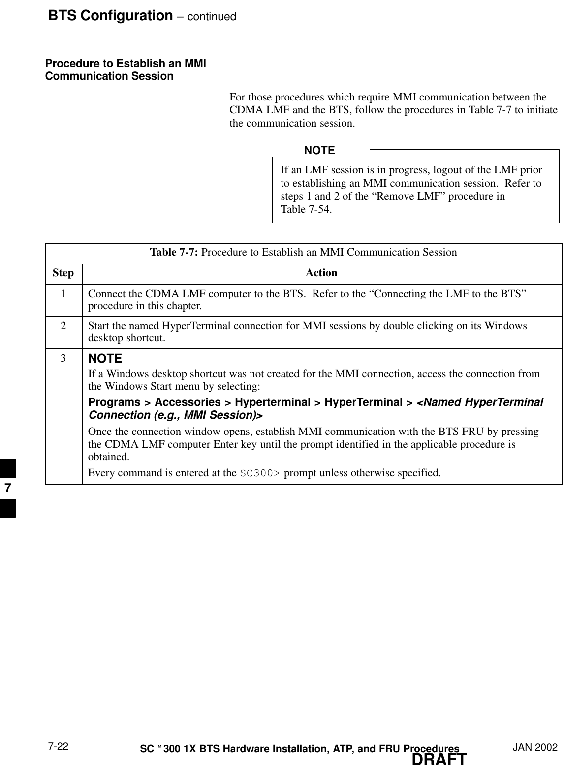
BTS Configuration – continuedDRAFTSCt300 1X BTS Hardware Installation, ATP, and FRU Procedures JAN 20027-22Procedure to Establish an MMICommunication SessionFor those procedures which require MMI communication between theCDMA LMF and the BTS, follow the procedures in Table 7-7 to initiatethe communication session.If an LMF session is in progress, logout of the LMF priorto establishing an MMI communication session.  Refer tosteps 1 and 2 of the “Remove LMF” procedure inTable 7-54.NOTETable 7-7: Procedure to Establish an MMI Communication SessionStep Action1Connect the CDMA LMF computer to the BTS.  Refer to the “Connecting the LMF to the BTS”procedure in this chapter.2Start the named HyperTerminal connection for MMI sessions by double clicking on its Windowsdesktop shortcut.3NOTEIf a Windows desktop shortcut was not created for the MMI connection, access the connection fromthe Windows Start menu by selecting:Programs > Accessories > Hyperterminal > HyperTerminal > <Named HyperTerminalConnection (e.g., MMI Session)>Once the connection window opens, establish MMI communication with the BTS FRU by pressingthe CDMA LMF computer Enter key until the prompt identified in the applicable procedure isobtained.Every command is entered at the SC300> prompt unless otherwise specified.7
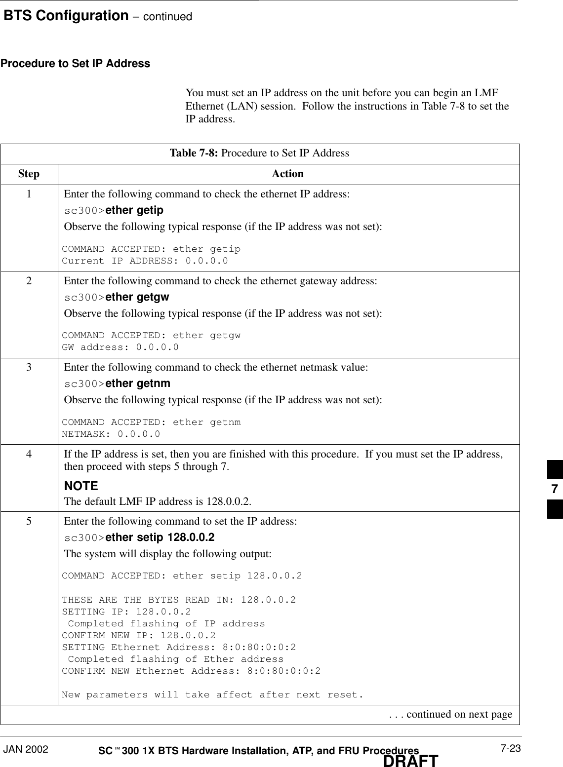
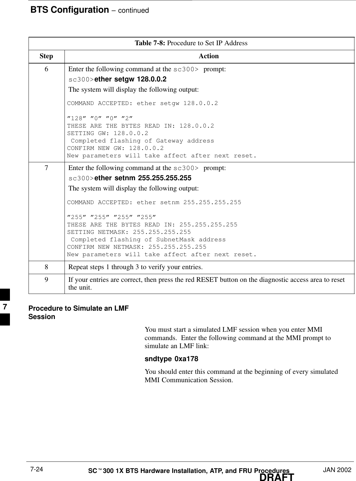
BTS Configuration – continuedJAN 2002 7-23SCt300 1X BTS Hardware Installation, ATP, and FRU ProceduresDRAFTProcedure to Set IP AddressYou must set an IP address on the unit before you can begin an LMFEthernet (LAN) session.  Follow the instructions in Table 7-8 to set theIP address.Table 7-8: Procedure to Set IP AddressStep Action1Enter the following command to check the ethernet IP address:sc300>ether getipObserve the following typical response (if the IP address was not set):COMMAND ACCEPTED: ether getipCurrent IP ADDRESS: 0.0.0.02Enter the following command to check the ethernet gateway address:sc300>ether getgwObserve the following typical response (if the IP address was not set):COMMAND ACCEPTED: ether getgwGW address: 0.0.0.03Enter the following command to check the ethernet netmask value:sc300>ether getnmObserve the following typical response (if the IP address was not set):COMMAND ACCEPTED: ether getnmNETMASK: 0.0.0.04If the IP address is set, then you are finished with this procedure.  If you must set the IP address,then proceed with steps 5 through 7.NOTEThe default LMF IP address is 128.0.0.2.5Enter the following command to set the IP address:sc300>ether setip 128.0.0.2The system will display the following output:COMMAND ACCEPTED: ether setip 128.0.0.2 THESE ARE THE BYTES READ IN: 128.0.0.2SETTING IP: 128.0.0.2 Completed flashing of IP addressCONFIRM NEW IP: 128.0.0.2SETTING Ethernet Address: 8:0:80:0:0:2 Completed flashing of Ether addressCONFIRM NEW Ethernet Address: 8:0:80:0:0:2New parameters will take affect after next reset. . . . continued on next page7
BTS Configuration – continuedDRAFTSCt300 1X BTS Hardware Installation, ATP, and FRU Procedures JAN 20027-24Table 7-8: Procedure to Set IP AddressStep Action6Enter the following command at the sc300> prompt:sc300>ether setgw 128.0.0.2The system will display the following output:COMMAND ACCEPTED: ether setgw 128.0.0.2 ”128” ”0” ”0” ”2”THESE ARE THE BYTES READ IN: 128.0.0.2SETTING GW: 128.0.0.2 Completed flashing of Gateway addressCONFIRM NEW GW: 128.0.0.2New parameters will take affect after next reset.7Enter the following command at the sc300> prompt:sc300>ether setnm 255.255.255.255The system will display the following output:COMMAND ACCEPTED: ether setnm 255.255.255.255”255” ”255” ”255” ”255”THESE ARE THE BYTES READ IN: 255.255.255.255SETTING NETMASK: 255.255.255.255 Completed flashing of SubnetMask addressCONFIRM NEW NETMASK: 255.255.255.255New parameters will take affect after next reset.8Repeat steps 1 through 3 to verify your entries.9If your entries are correct, then press the red RESET button on the diagnostic access area to resetthe unit.Procedure to Simulate an LMFSessionYou must start a simulated LMF session when you enter MMIcommands.  Enter the following command at the MMI prompt tosimulate an LMF link:sndtype 0xa178You should enter this command at the beginning of every simulatedMMI Communication Session.7
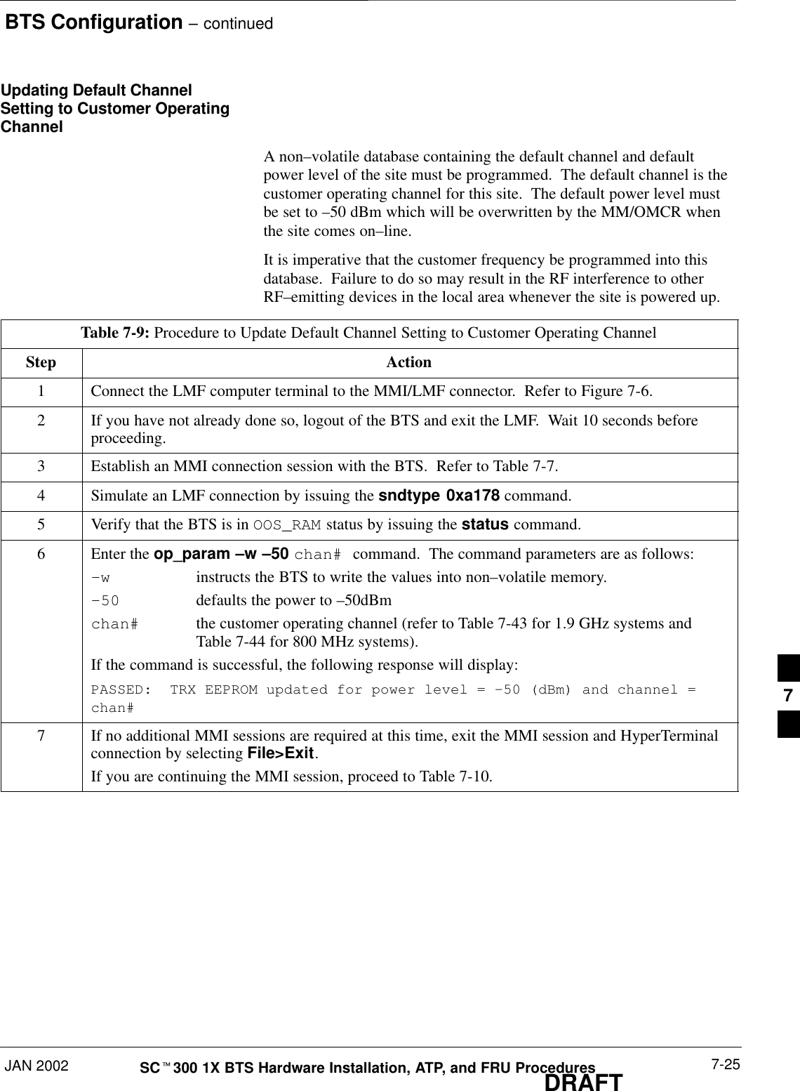
BTS Configuration – continuedJAN 2002 7-25SCt300 1X BTS Hardware Installation, ATP, and FRU ProceduresDRAFTUpdating Default ChannelSetting to Customer OperatingChannelA non–volatile database containing the default channel and defaultpower level of the site must be programmed.  The default channel is thecustomer operating channel for this site.  The default power level mustbe set to –50 dBm which will be overwritten by the MM/OMCR whenthe site comes on–line.It is imperative that the customer frequency be programmed into thisdatabase.  Failure to do so may result in the RF interference to otherRF–emitting devices in the local area whenever the site is powered up.Table 7-9: Procedure to Update Default Channel Setting to Customer Operating ChannelStep Action1Connect the LMF computer terminal to the MMI/LMF connector.  Refer to Figure 7-6.2If you have not already done so, logout of the BTS and exit the LMF.  Wait 10 seconds beforeproceeding.3Establish an MMI connection session with the BTS.  Refer to Table 7-7.4Simulate an LMF connection by issuing the sndtype 0xa178 command.5Verify that the BTS is in OOS_RAM status by issuing the status command.6Enter the op_param –w –50 chan# command.  The command parameters are as follows:–winstructs the BTS to write the values into non–volatile memory.–50 defaults the power to –50dBmchan# the customer operating channel (refer to Table 7-43 for 1.9 GHz systems and Table 7-44 for 800 MHz systems).If the command is successful, the following response will display:PASSED:  TRX EEPROM updated for power level = –50 (dBm) and channel =chan#7If no additional MMI sessions are required at this time, exit the MMI session and HyperTerminalconnection by selecting File>Exit.If you are continuing the MMI session, proceed to Table 7-10.7
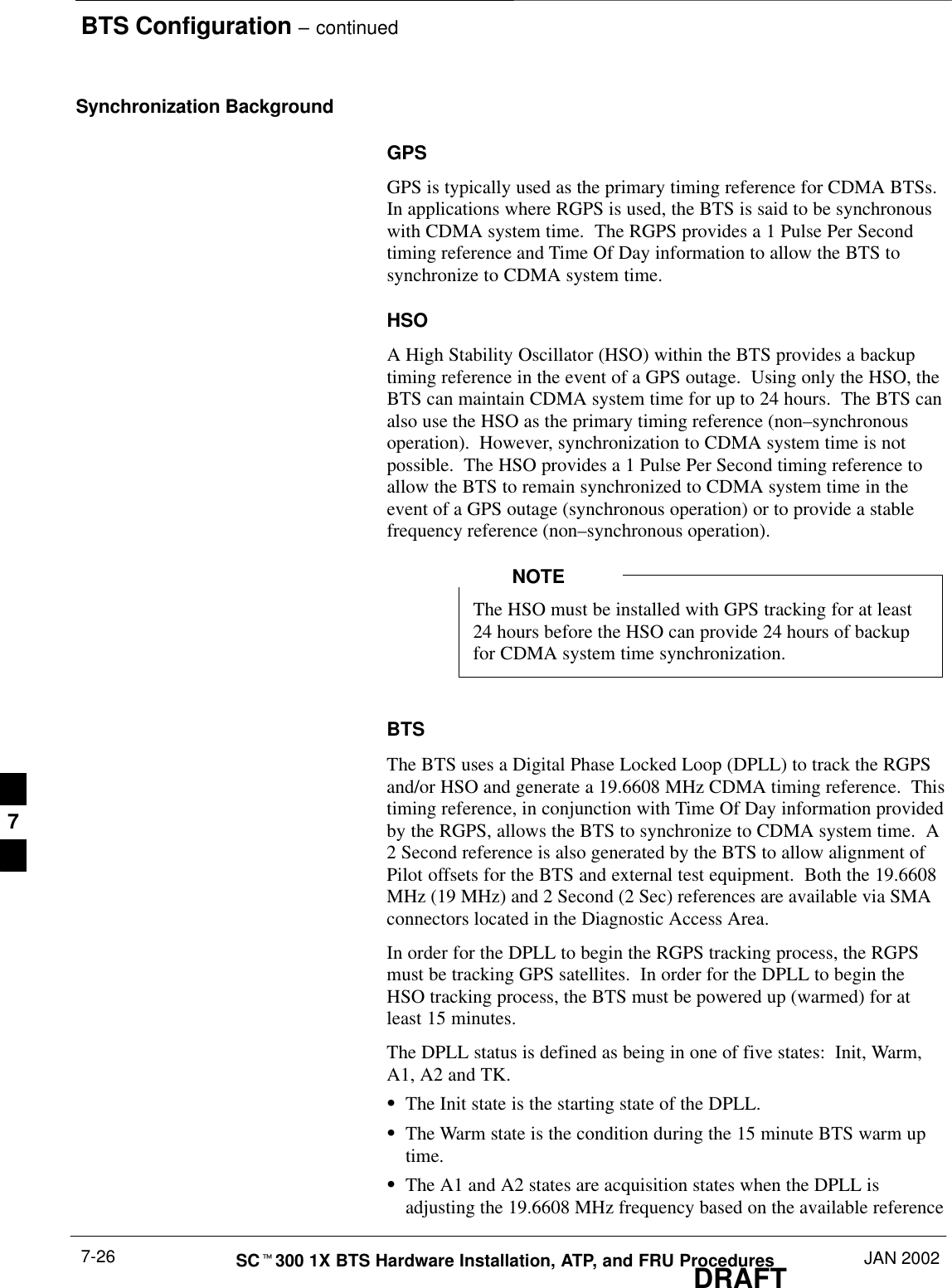
BTS Configuration – continuedDRAFTSCt300 1X BTS Hardware Installation, ATP, and FRU Procedures JAN 20027-26Synchronization BackgroundGPSGPS is typically used as the primary timing reference for CDMA BTSs.In applications where RGPS is used, the BTS is said to be synchronouswith CDMA system time.  The RGPS provides a 1 Pulse Per Secondtiming reference and Time Of Day information to allow the BTS tosynchronize to CDMA system time.HSOA High Stability Oscillator (HSO) within the BTS provides a backuptiming reference in the event of a GPS outage.  Using only the HSO, theBTS can maintain CDMA system time for up to 24 hours.  The BTS canalso use the HSO as the primary timing reference (non–synchronousoperation).  However, synchronization to CDMA system time is notpossible.  The HSO provides a 1 Pulse Per Second timing reference toallow the BTS to remain synchronized to CDMA system time in theevent of a GPS outage (synchronous operation) or to provide a stablefrequency reference (non–synchronous operation).The HSO must be installed with GPS tracking for at least24 hours before the HSO can provide 24 hours of backupfor CDMA system time synchronization.NOTEBTSThe BTS uses a Digital Phase Locked Loop (DPLL) to track the RGPSand/or HSO and generate a 19.6608 MHz CDMA timing reference.  Thistiming reference, in conjunction with Time Of Day information providedby the RGPS, allows the BTS to synchronize to CDMA system time.  A2 Second reference is also generated by the BTS to allow alignment ofPilot offsets for the BTS and external test equipment.  Both the 19.6608MHz (19 MHz) and 2 Second (2 Sec) references are available via SMAconnectors located in the Diagnostic Access Area.In order for the DPLL to begin the RGPS tracking process, the RGPSmust be tracking GPS satellites.  In order for the DPLL to begin theHSO tracking process, the BTS must be powered up (warmed) for atleast 15 minutes.The DPLL status is defined as being in one of five states:  Init, Warm,A1, A2 and TK.SThe Init state is the starting state of the DPLL.SThe Warm state is the condition during the 15 minute BTS warm uptime.SThe A1 and A2 states are acquisition states when the DPLL isadjusting the 19.6608 MHz frequency based on the available reference7
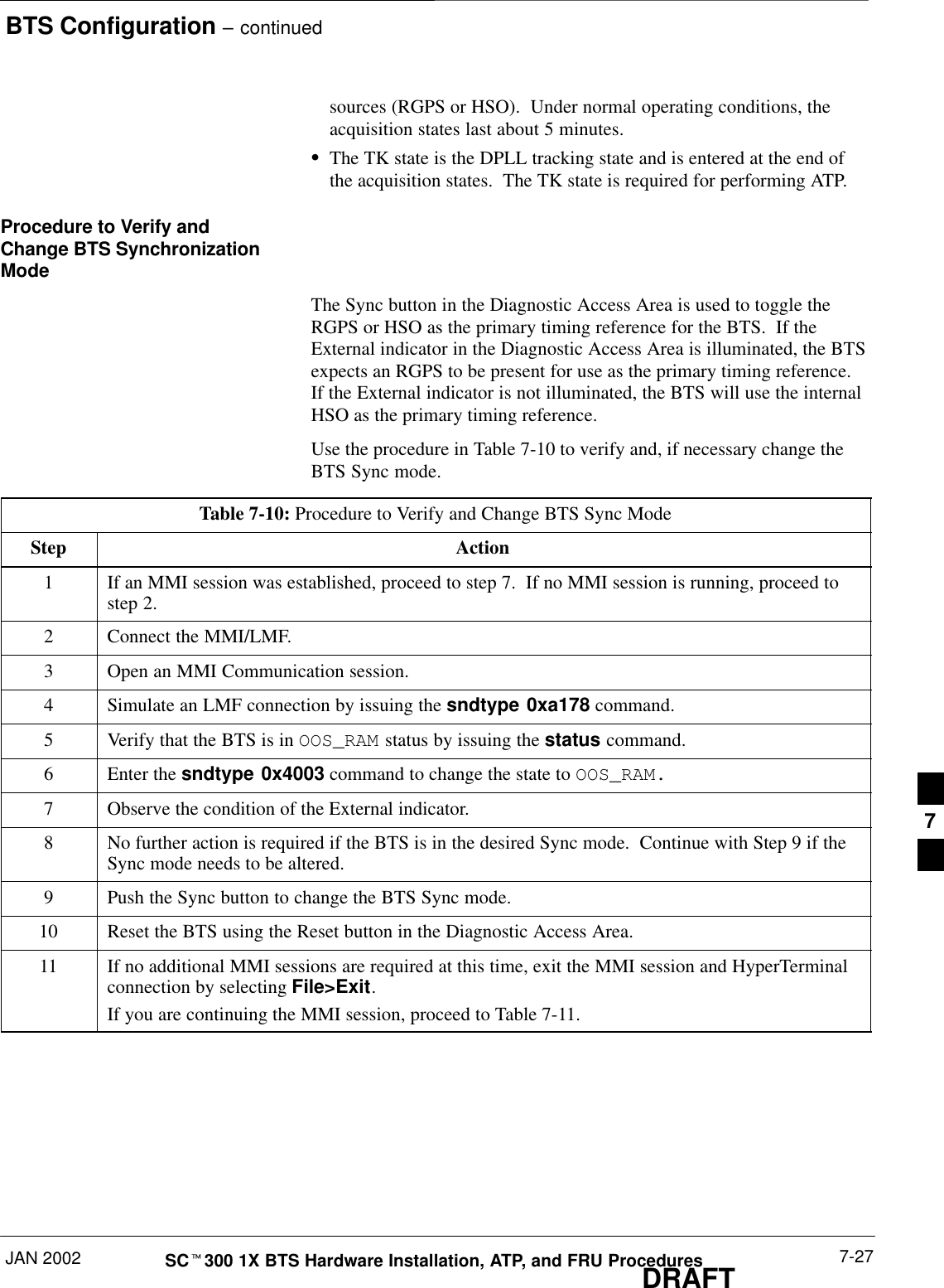
BTS Configuration – continuedJAN 2002 7-27SCt300 1X BTS Hardware Installation, ATP, and FRU ProceduresDRAFTsources (RGPS or HSO).  Under normal operating conditions, theacquisition states last about 5 minutes.SThe TK state is the DPLL tracking state and is entered at the end ofthe acquisition states.  The TK state is required for performing ATP.Procedure to Verify andChange BTS SynchronizationModeThe Sync button in the Diagnostic Access Area is used to toggle theRGPS or HSO as the primary timing reference for the BTS.  If theExternal indicator in the Diagnostic Access Area is illuminated, the BTSexpects an RGPS to be present for use as the primary timing reference.If the External indicator is not illuminated, the BTS will use the internalHSO as the primary timing reference.Use the procedure in Table 7-10 to verify and, if necessary change theBTS Sync mode.Table 7-10: Procedure to Verify and Change BTS Sync ModeStep Action1If an MMI session was established, proceed to step 7.  If no MMI session is running, proceed tostep 2.2Connect the MMI/LMF.3Open an MMI Communication session.4Simulate an LMF connection by issuing the sndtype 0xa178 command.5Verify that the BTS is in OOS_RAM status by issuing the status command.6Enter the sndtype 0x4003 command to change the state to OOS_RAM.7Observe the condition of the External indicator.8No further action is required if the BTS is in the desired Sync mode.  Continue with Step 9 if theSync mode needs to be altered.9Push the Sync button to change the BTS Sync mode.10 Reset the BTS using the Reset button in the Diagnostic Access Area.11 If no additional MMI sessions are required at this time, exit the MMI session and HyperTerminalconnection by selecting File>Exit.If you are continuing the MMI session, proceed to Table 7-11.7
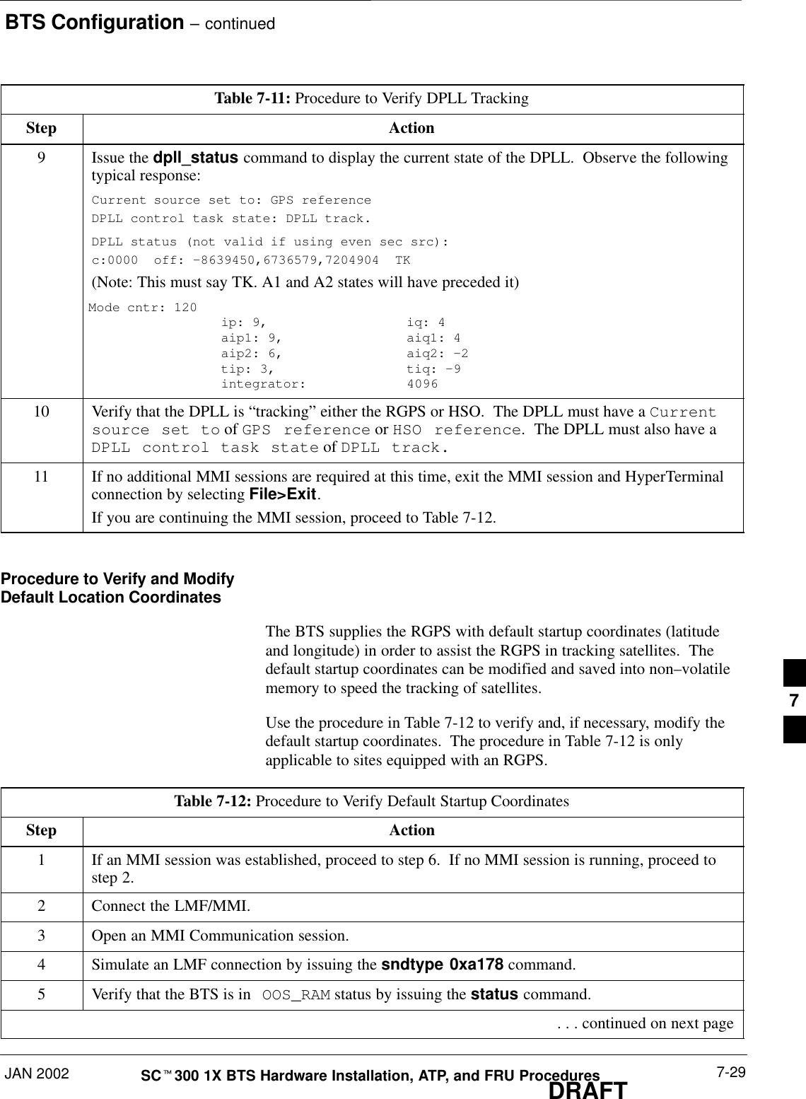
BTS Configuration – continuedDRAFTSCt300 1X BTS Hardware Installation, ATP, and FRU Procedures JAN 20027-28Procedure to Verify DPLLTracking (RGPS/HSO)The DPLL within the BTS must be tracking either RGPS or HSO inorder to perform ATP.  Use the procedure in Table 7-11 to verify DPLLtracking.Table 7-11: Procedure to Verify DPLL TrackingStep Action1If an MMI session was established, proceed to step 6.  If no MMI session is running, proceed tostep 2.2Connect the MMI/LMF.3Open an MMI Communication session.4Simulate an LMF connection by issuing the sndtype 0xa178 command.5Verify that the BTS is in OOS_RAM status by issuing the status command.6If an RGPS is not present, go to Step 9.7Enter the gps_status command to display the current state of the RGPS.  Observe the followingtypical response:gps_statusGPS Receiver Identification:Current GPS Time :8 03 1999   23:01:12Current GPS Receiver Status :8Number of Satellites Currently visible :11Number of Satellites Currently received :5Number of Satellites Currently tracked :5GPS Receiver Type :UTCurrent GPS Task State :GPS_TRACKCurrent Dilution of Precision (HDOP (2D)/antenna ok [0x01]): 0Chan: 0, SVID: 9, Mode: 8, RSSI: 44, Status: 0xaaChan: 1, SVID: 4, Mode: 8, RSSI: 46, Status: 0xaaChan: 2, SVID: 10, Mode: 8, RSSI: 44, Status: 0xaaChan: 3, SVID: 6, Mode: 8, RSSI: 41, Status: 0xaaChan: 4, SVID: 7, Mode: 8, RSSI: 43, Status: 0xaaChan: 5, SVID: 24, Mode: 8, RSSI: 47, Status: 0xaaChan: 6, SVID: 30, Mode: 8, RSSI: 45, Status: 0xaaChan: 7, SVID: 5, Mode: 8, RSSI: 48, Status: 0xaaCurrent Longitude: –350250952Current Latitude: 118244730Current Height: 240198The RGPS must have a Current GPS Task State of GPS_TRACK to proceed.NOTEGPS tracking times vary depending on location and installation. . . . continued on next page7
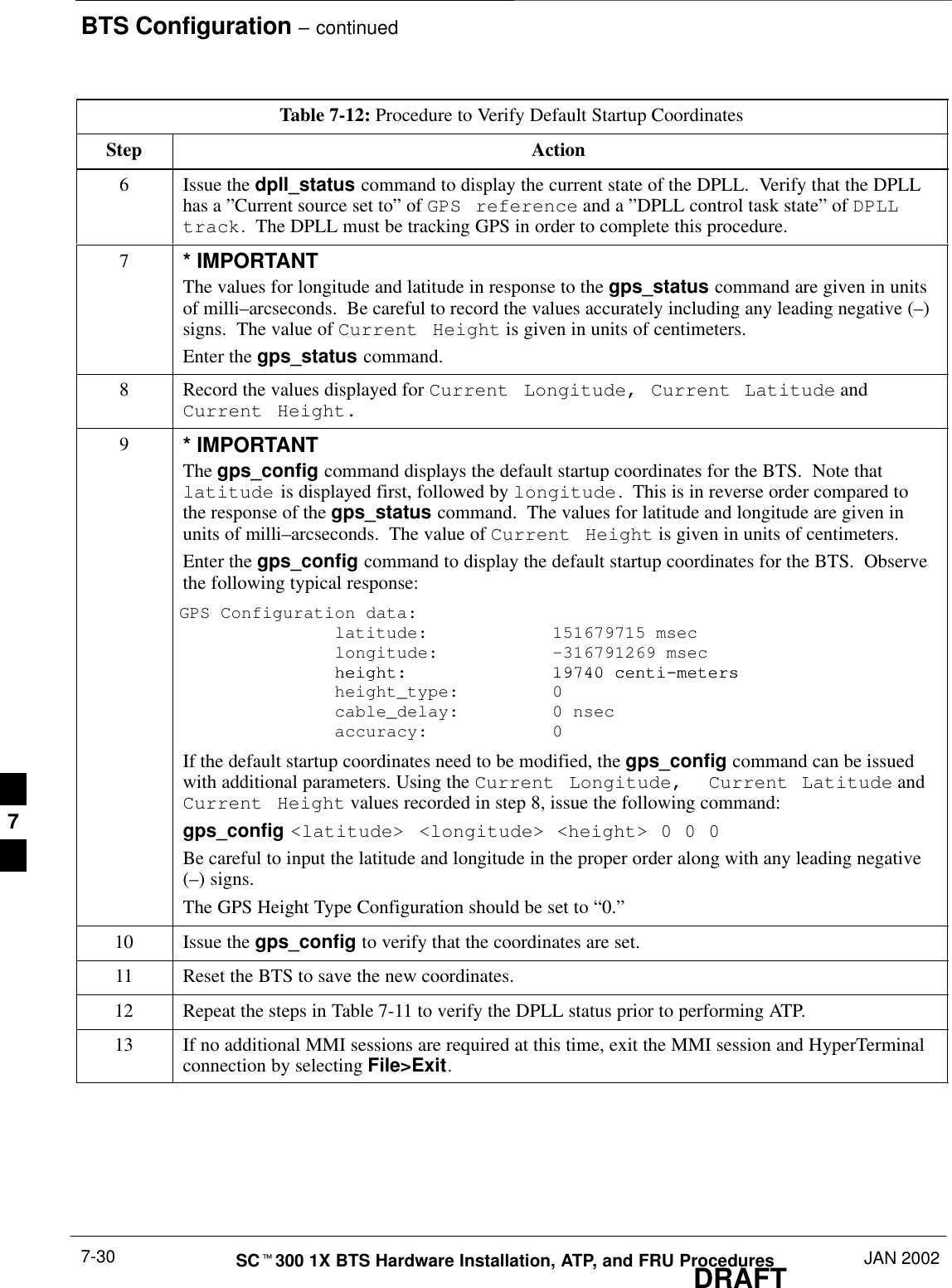
BTS Configuration – continuedJAN 2002 7-29SCt300 1X BTS Hardware Installation, ATP, and FRU ProceduresDRAFTTable 7-11: Procedure to Verify DPLL TrackingStep Action9Issue the dpll_status command to display the current state of the DPLL.  Observe the followingtypical response:Current source set to: GPS referenceDPLL control task state: DPLL track.DPLL status (not valid if using even sec src): c:0000  off: –8639450,6736579,7204904  TK(Note: This must say TK. A1 and A2 states will have preceded it)Mode cntr: 120   ip: 9,    iq: 4aip1: 9,  aiq1: 4aip2: 6,  aiq2: –2  tip: 3,   tiq: –9integrator:  409610 Verify that the DPLL is “tracking” either the RGPS or HSO.  The DPLL must have a Currentsource set to of GPS reference or HSO reference.  The DPLL must also have aDPLL control task state of DPLL track.11 If no additional MMI sessions are required at this time, exit the MMI session and HyperTerminalconnection by selecting File>Exit.If you are continuing the MMI session, proceed to Table 7-12.Procedure to Verify and ModifyDefault Location CoordinatesThe BTS supplies the RGPS with default startup coordinates (latitudeand longitude) in order to assist the RGPS in tracking satellites.  Thedefault startup coordinates can be modified and saved into non–volatilememory to speed the tracking of satellites.Use the procedure in Table 7-12 to verify and, if necessary, modify thedefault startup coordinates.  The procedure in Table 7-12 is onlyapplicable to sites equipped with an RGPS.Table 7-12: Procedure to Verify Default Startup CoordinatesStep Action1If an MMI session was established, proceed to step 6.  If no MMI session is running, proceed tostep 2.2Connect the LMF/MMI.3Open an MMI Communication session.4Simulate an LMF connection by issuing the sndtype 0xa178 command.5Verify that the BTS is in OOS_RAM status by issuing the status command. . . . continued on next page7
BTS Configuration – continuedDRAFTSCt300 1X BTS Hardware Installation, ATP, and FRU Procedures JAN 20027-30Table 7-12: Procedure to Verify Default Startup CoordinatesStep Action6Issue the dpll_status command to display the current state of the DPLL.  Verify that the DPLLhas a ”Current source set to” of GPS reference and a ”DPLL control task state” of DPLLtrack.  The DPLL must be tracking GPS in order to complete this procedure.7* IMPORTANTThe values for longitude and latitude in response to the gps_status command are given in unitsof milli–arcseconds.  Be careful to record the values accurately including any leading negative (–)signs.  The value of Current Height is given in units of centimeters.Enter the gps_status command.8Record the values displayed for Current Longitude, Current Latitude andCurrent Height.9* IMPORTANTThe gps_config command displays the default startup coordinates for the BTS.  Note thatlatitude is displayed first, followed by longitude.  This is in reverse order compared tothe response of the gps_status command.  The values for latitude and longitude are given inunits of milli–arcseconds.  The value of Current Height is given in units of centimeters.Enter the gps_config command to display the default startup coordinates for the BTS.  Observethe following typical response:GPS Configuration data:   latitude:   151679715 msec   longitude: –316791269 msecheight: 19740 centi–meters   height: 19740 centi–meters    height_type:  0    cable_delay:  0 nsec    accuracy:  0If the default startup coordinates need to be modified, the gps_config command can be issuedwith additional parameters. Using the Current Longitude,  Current Latitude andCurrent Height values recorded in step 8, issue the following command:gps_config <latitude> <longitude> <height> 0 0 0Be careful to input the latitude and longitude in the proper order along with any leading negative(–) signs.The GPS Height Type Configuration should be set to “0.”10 Issue the gps_config to verify that the coordinates are set.11 Reset the BTS to save the new coordinates.12 Repeat the steps in Table 7-11 to verify the DPLL status prior to performing ATP.13 If no additional MMI sessions are required at this time, exit the MMI session and HyperTerminalconnection by selecting File>Exit.7
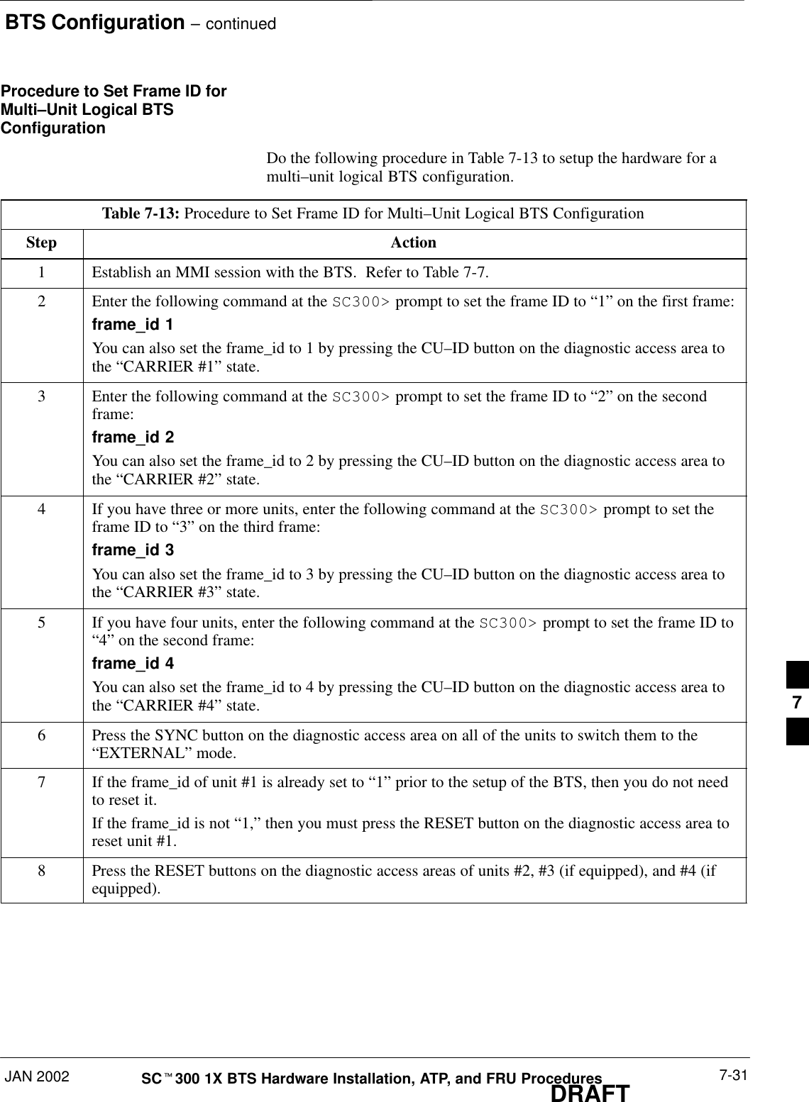
BTS Configuration – continuedJAN 2002 7-31SCt300 1X BTS Hardware Installation, ATP, and FRU ProceduresDRAFTProcedure to Set Frame ID forMulti–Unit Logical BTSConfigurationDo the following procedure in Table 7-13 to setup the hardware for amulti–unit logical BTS configuration.Table 7-13: Procedure to Set Frame ID for Multi–Unit Logical BTS ConfigurationStep Action1Establish an MMI session with the BTS.  Refer to Table 7-7.2Enter the following command at the SC300> prompt to set the frame ID to “1” on the first frame:frame_id 1You can also set the frame_id to 1 by pressing the CU–ID button on the diagnostic access area tothe “CARRIER #1” state.3Enter the following command at the SC300> prompt to set the frame ID to “2” on the secondframe:frame_id 2You can also set the frame_id to 2 by pressing the CU–ID button on the diagnostic access area tothe “CARRIER #2” state.4If you have three or more units, enter the following command at the SC300> prompt to set theframe ID to “3” on the third frame:frame_id 3You can also set the frame_id to 3 by pressing the CU–ID button on the diagnostic access area tothe “CARRIER #3” state.5If you have four units, enter the following command at the SC300> prompt to set the frame ID to“4” on the second frame:frame_id 4You can also set the frame_id to 4 by pressing the CU–ID button on the diagnostic access area tothe “CARRIER #4” state.6Press the SYNC button on the diagnostic access area on all of the units to switch them to the“EXTERNAL” mode.7If the frame_id of unit #1 is already set to “1” prior to the setup of the BTS, then you do not needto reset it.If the frame_id is not “1,” then you must press the RESET button on the diagnostic access area toreset unit #1.8Press the RESET buttons on the diagnostic access areas of units #2, #3 (if equipped), and #4 (ifequipped).7
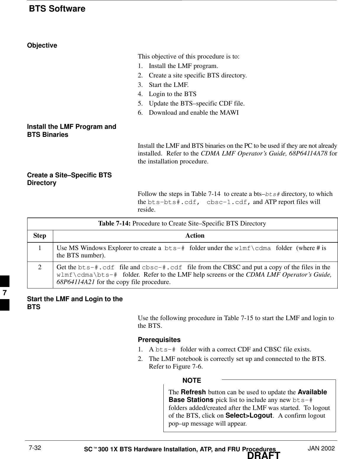
BTS SoftwareDRAFTSCt300 1X BTS Hardware Installation, ATP, and FRU Procedures JAN 20027-32ObjectiveThis objective of this procedure is to:1. Install the LMF program.2. Create a site specific BTS directory.3. Start the LMF.4. Login to the BTS5. Update the BTS–specific CDF file.6. Download and enable the MAWIInstall the LMF Program andBTS BinariesInstall the LMF and BTS binaries on the PC to be used if they are not alreadyinstalled.  Refer to the CDMA LMF Operator’s Guide, 68P64114A78 forthe installation procedure.Create a Site–Specific BTSDirectoryFollow the steps in Table 7-14  to create a bts–bts# directory, to whichthe bts–bts#.cdf,  cbsc–1.cdf, and ATP report files willreside.Table 7-14: Procedure to Create Site–Specific BTS DirectoryStep Action1Use MS Windows Explorer to create a  bts–# folder under the wlmf\cdma folder (where # isthe BTS number).2Get the bts–#.cdf file and cbsc–#.cdf file from the CBSC and put a copy of the files in thewlmf\cdma\bts–# folder.  Refer to the LMF help screens or the CDMA LMF Operator’s Guide,68P64114A21 for the copy file procedure.Start the LMF and Login to theBTSUse the following procedure in Table 7-15 to start the LMF and login tothe BTS.Prerequisites1. A bts–# folder with a correct CDF and CBSC file exists.2. The LMF notebook is correctly set up and connected to the BTS.Refer to Figure 7-6.The Refresh button can be used to update the AvailableBase Stations pick list to include any new bts–#folders added/created after the LMF was started.  To logoutof the BTS, click on Select>Logout.  A confirm logoutpop–up message will appear.NOTE7
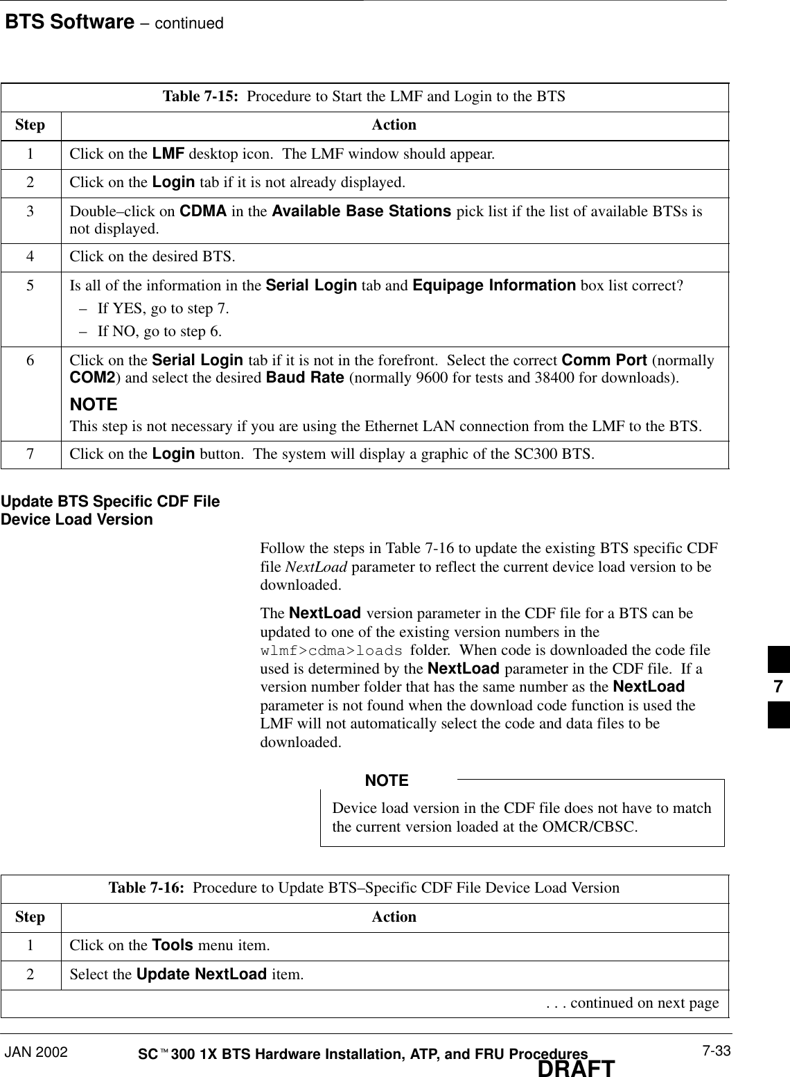
BTS Software – continuedJAN 2002 7-33SCt300 1X BTS Hardware Installation, ATP, and FRU ProceduresDRAFTTable 7-15:  Procedure to Start the LMF and Login to the BTSStep Action1Click on the LMF desktop icon.  The LMF window should appear.2Click on the Login tab if it is not already displayed.3 Double–click on CDMA in the Available Base Stations pick list if the list of available BTSs isnot displayed.4Click on the desired BTS.5Is all of the information in the Serial Login tab and Equipage Information box list correct?–If YES, go to step 7.–If NO, go to step 6.6Click on the Serial Login tab if it is not in the forefront.  Select the correct Comm Port (normallyCOM2) and select the desired Baud Rate (normally 9600 for tests and 38400 for downloads).NOTEThis step is not necessary if you are using the Ethernet LAN connection from the LMF to the BTS.7Click on the Login button.  The system will display a graphic of the SC300 BTS.Update BTS Specific CDF FileDevice Load VersionFollow the steps in Table 7-16 to update the existing BTS specific CDFfile NextLoad parameter to reflect the current device load version to bedownloaded.The NextLoad version parameter in the CDF file for a BTS can beupdated to one of the existing version numbers in thewlmf>cdma>loads  folder.  When code is downloaded the code fileused is determined by the NextLoad parameter in the CDF file.  If aversion number folder that has the same number as the NextLoadparameter is not found when the download code function is used theLMF will not automatically select the code and data files to bedownloaded.Device load version in the CDF file does not have to matchthe current version loaded at the OMCR/CBSC.NOTETable 7-16:  Procedure to Update BTS–Specific CDF File Device Load VersionStep Action1Click on the Tools menu item.2Select the Update NextLoad item. . . . continued on next page7
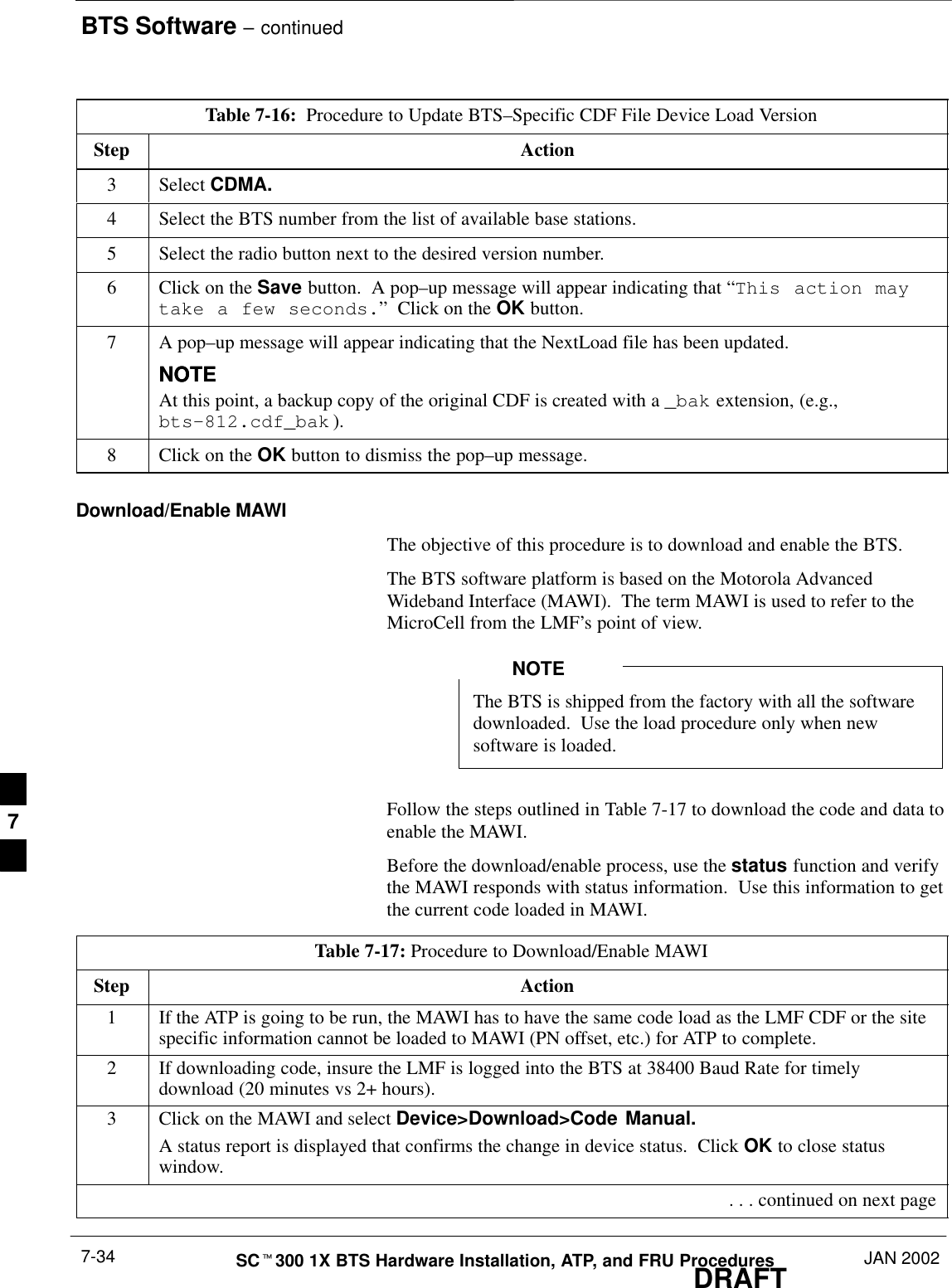
BTS Software – continuedDRAFTSCt300 1X BTS Hardware Installation, ATP, and FRU Procedures JAN 20027-34Table 7-16:  Procedure to Update BTS–Specific CDF File Device Load VersionStep Action3 Select CDMA.4Select the BTS number from the list of available base stations.5Select the radio button next to the desired version number.6Click on the Save button.  A pop–up message will appear indicating that “This action maytake a few seconds.”  Click on the OK button.7A pop–up message will appear indicating that the NextLoad file has been updated.NOTENOTEAt this point, a backup copy of the original CDF is created with a _bak extension, (e.g.,bts–812.cdf_bak ).8Click on the OK button to dismiss the pop–up message.Download/Enable MAWIThe objective of this procedure is to download and enable the BTS.The BTS software platform is based on the Motorola AdvancedWideband Interface (MAWI).  The term MAWI is used to refer to theMicroCell from the LMF’s point of view.The BTS is shipped from the factory with all the softwaredownloaded.  Use the load procedure only when newsoftware is loaded.NOTEFollow the steps outlined in Table 7-17 to download the code and data toenable the MAWI.Before the download/enable process, use the status function and verifythe MAWI responds with status information.  Use this information to getthe current code loaded in MAWI.Table 7-17: Procedure to Download/Enable MAWIStep Action1If the ATP is going to be run, the MAWI has to have the same code load as the LMF CDF or the sitespecific information cannot be loaded to MAWI (PN offset, etc.) for ATP to complete.2If downloading code, insure the LMF is logged into the BTS at 38400 Baud Rate for timelydownload (20 minutes vs 2+ hours).3Click on the MAWI and select Device>Download>Code Manual.A status report is displayed that confirms the change in device status.  Click OK to close statuswindow. . . . continued on next page7
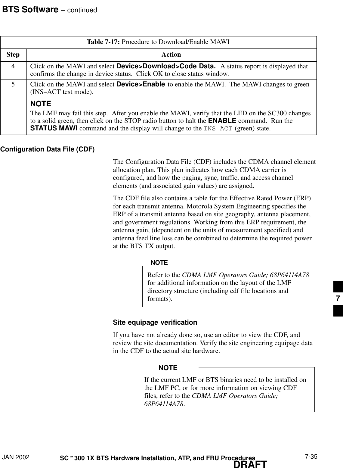
BTS Software – continuedJAN 2002 7-35SCt300 1X BTS Hardware Installation, ATP, and FRU ProceduresDRAFTTable 7-17: Procedure to Download/Enable MAWIStep Action4Click on the MAWI and select Device>Download>Code Data.  A status report is displayed thatconfirms the change in device status.  Click OK to close status window.5Click on the MAWI and select Device>Enable to enable the MAWI.  The MAWI changes to green(INS–ACT test mode).NOTENOTEThe LMF may fail this step.  After you enable the MAWI, verify that the LED on the SC300 changesto a solid green, then click on the STOP radio button to halt the ENABLE command.  Run theSTATUS MAWI command and the display will change to the INS_ACT (green) state.Configuration Data File (CDF)The Configuration Data File (CDF) includes the CDMA channel elementallocation plan. This plan indicates how each CDMA carrier isconfigured, and how the paging, sync, traffic, and access channelelements (and associated gain values) are assigned.The CDF file also contains a table for the Effective Rated Power (ERP)for each transmit antenna. Motorola System Engineering specifies theERP of a transmit antenna based on site geography, antenna placement,and government regulations. Working from this ERP requirement, theantenna gain, (dependent on the units of measurement specified) andantenna feed line loss can be combined to determine the required powerat the BTS TX output.Refer to the CDMA LMF Operators Guide; 68P64114A78for additional information on the layout of the LMFdirectory structure (including cdf file locations andformats).NOTESite equipage verificationIf you have not already done so, use an editor to view the CDF, andreview the site documentation. Verify the site engineering equipage datain the CDF to the actual site hardware.If the current LMF or BTS binaries need to be installed onthe LMF PC, or for more information on viewing CDFfiles, refer to the CDMA LMF Operators Guide;68P64114A78. NOTE7
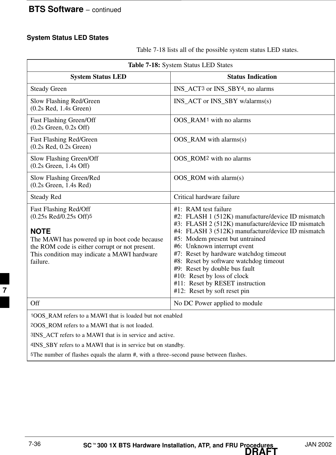
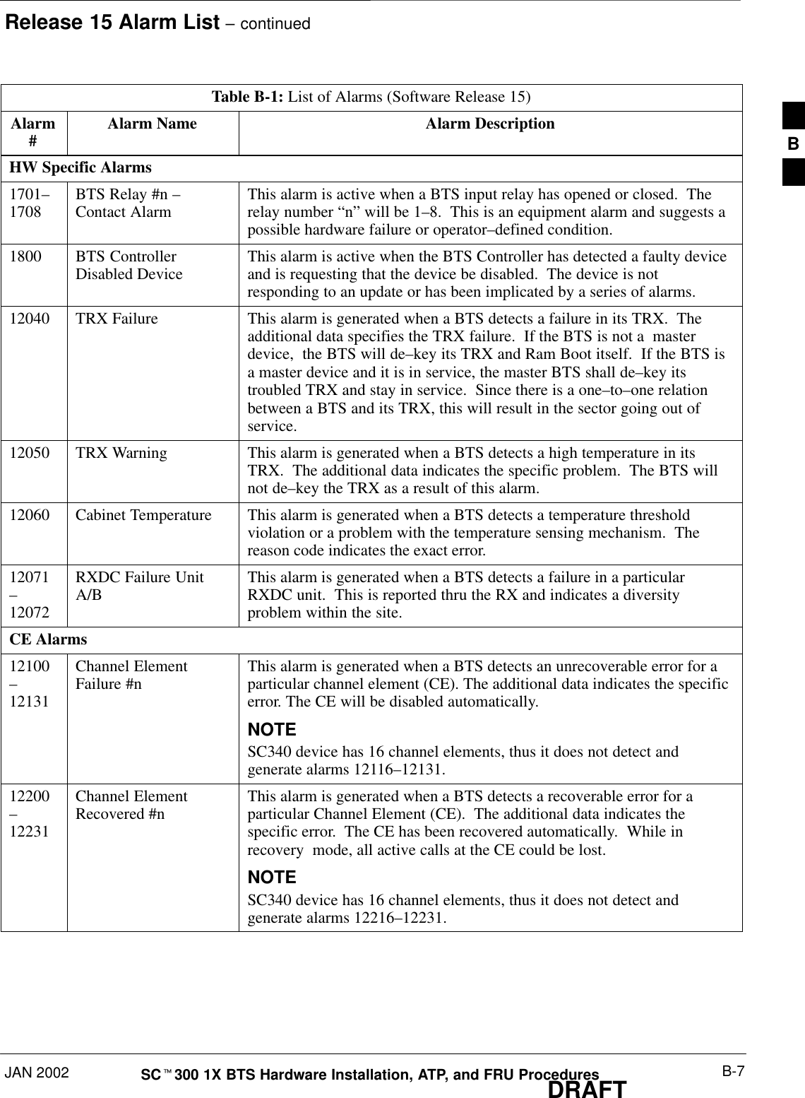
BTS Software – continuedDRAFTSCt300 1X BTS Hardware Installation, ATP, and FRU Procedures JAN 20027-36System Status LED StatesTable 7-18 lists all of the possible system status LED states.Table 7-18: System Status LED StatesSystem Status LED Status IndicationSteady Green INS_ACT# or INS_SBY$, no alarmsSlow Flashing Red/Green(0.2s Red, 1.4s Green) INS_ACT or INS_SBY w/alarms(s)Fast Flashing Green/Off(0.2s Green, 0.2s Off) OOS_RAM! with no alarmsFast Flashing Red/Green(0.2s Red, 0.2s Green) OOS_RAM with alarms(s)Slow Flashing Green/Off(0.2s Green, 1.4s Off) OOS_ROM@ with no alarmsSlow Flashing Green/Red(0.2s Green, 1.4s Red) OOS_ROM with alarm(s)Steady Red Critical hardware failureFast Flashing Red/Off(0.25s Red/0.25s Off)%NOTEThe MAWI has powered up in boot code becausethe ROM code is either corrupt or not present.This condition may indicate a MAWI hardwarefailure.#1:  RAM test failure#2:  FLASH 1 (512K) manufacture/device ID mismatch#3:  FLASH 2 (512K) manufacture/device ID mismatch#4:  FLASH 3 (512K) manufacture/device ID mismatch#5:  Modem present but untrained#6:  Unknown interrupt event#7:  Reset by hardware watchdog timeout#8:  Reset by software watchdog timeout#9:  Reset by double bus fault#10:  Reset by loss of clock#11:  Reset by RESET instruction#12:  Reset by soft reset pinOff No DC Power applied to module!OOS_RAM refers to a MAWI that is loaded but not enabled@OOS_ROM refers to a MAWI that is not loaded.#INS_ACT refers to a MAWI that is in service and active.$INS_SBY refers to a MAWI that is in service but on standby.%The number of flashes equals the alarm #, with a three–second pause between flashes.7
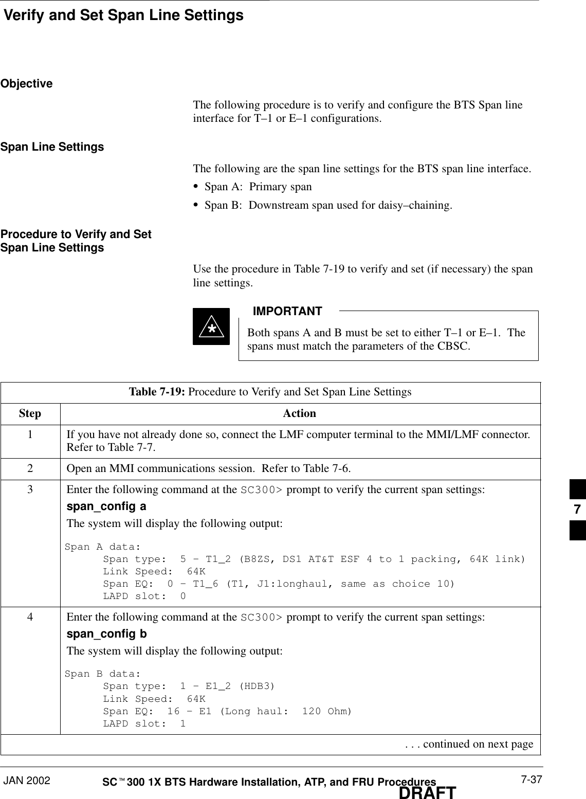
Verify and Set Span Line SettingsJAN 2002 7-37SCt300 1X BTS Hardware Installation, ATP, and FRU ProceduresDRAFTObjectiveThe following procedure is to verify and configure the BTS Span lineinterface for T–1 or E–1 configurations.Span Line SettingsThe following are the span line settings for the BTS span line interface.SSpan A:  Primary spanSSpan B:  Downstream span used for daisy–chaining.Procedure to Verify and SetSpan Line SettingsUse the procedure in Table 7-19 to verify and set (if necessary) the spanline settings.Both spans A and B must be set to either T–1 or E–1.  Thespans must match the parameters of the CBSC.IMPORTANT*Table 7-19: Procedure to Verify and Set Span Line SettingsStep Action1If you have not already done so, connect the LMF computer terminal to the MMI/LMF connector.Refer to Table 7-7.2Open an MMI communications session.  Refer to Table 7-6.3Enter the following command at the SC300> prompt to verify the current span settings:span_config aThe system will display the following output:Span A data:Span type:  5 – T1_2 (B8ZS, DS1 AT&T ESF 4 to 1 packing, 64K link)Link Speed:  64KSpan EQ:  0 – T1_6 (T1, J1:longhaul, same as choice 10)LAPD slot:  04Enter the following command at the SC300> prompt to verify the current span settings:span_config bThe system will display the following output:Span B data:Span type:  1 – E1_2 (HDB3)Link Speed:  64KSpan EQ:  16 – E1 (Long haul:  120 Ohm)LAPD slot:  1 . . . continued on next page7
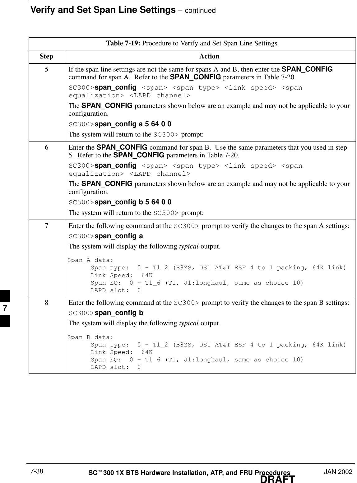
Verify and Set Span Line Settings – continuedDRAFTSCt300 1X BTS Hardware Installation, ATP, and FRU Procedures JAN 20027-38Table 7-19: Procedure to Verify and Set Span Line SettingsStep Action5If the span line settings are not the same for spans A and B, then enter the SPAN_CONFIGcommand for span A.  Refer to the SPAN_CONFIG parameters in Table 7-20.SC300>span_config <span> <span type> <link speed> <spanequalization> <LAPD channel>The SPAN_CONFIG parameters shown below are an example and may not be applicable to yourconfiguration.SC300>span_config a 5 64 0 0The system will return to the SC300> prompt:6Enter the SPAN_CONFIG command for span B.  Use the same parameters that you used in step5.  Refer to the SPAN_CONFIG parameters in Table 7-20.SC300>span_config <span> <span type> <link speed> <spanequalization> <LAPD channel>The SPAN_CONFIG parameters shown below are an example and may not be applicable to yourconfiguration.SC300>span_config b 5 64 0 0The system will return to the SC300> prompt:7Enter the following command at the SC300> prompt to verify the changes to the span A settings:SC300>span_config aThe system will display the following typical output.Span A data:Span type:  5 – T1_2 (B8ZS, DS1 AT&T ESF 4 to 1 packing, 64K link)Link Speed:  64KSpan EQ:  0 – T1_6 (T1, J1:longhaul, same as choice 10)LAPD slot:  08Enter the following command at the SC300> prompt to verify the changes to the span B settings:SC300>span_config bThe system will display the following typical output.Span B data:Span type:  5 – T1_2 (B8ZS, DS1 AT&T ESF 4 to 1 packing, 64K link)Link Speed:  64KSpan EQ:  0 – T1_6 (T1, J1:longhaul, same as choice 10)LAPD slot:  07
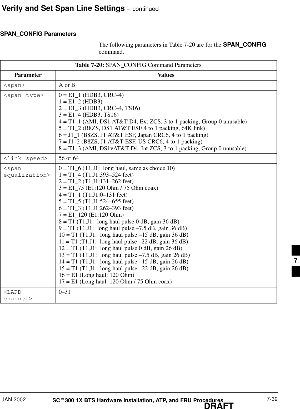
Verify and Set Span Line Settings – continuedJAN 2002 7-39SCt300 1X BTS Hardware Installation, ATP, and FRU ProceduresDRAFTSPAN_CONFIG ParametersThe following parameters in Table 7-20 are for the SPAN_CONFIGcommand.Table 7-20: SPAN_CONFIG Command ParametersParameter Values<span> A or B<span type> 0 = E1_1 (HDB3, CRC–4)1 = E1_2 (HDB3)2 = E1_3 (HDB3, CRC–4, TS16)3 = E1_4 (HDB3, TS16)4 = T1_1 (AMI, DS1 AT&T D4, Ext ZCS, 3 to 1 packing, Group 0 unusable)5 = T1_2 (B8ZS, DS1 AT&T ESF 4 to 1 packing, 64K link)6 = J1_1 (B8ZS, J1 AT&T ESF, Japan CRC6, 4 to 1 packing)7 = J1_2 (B8ZS, J1 AT&T ESF, US CRC6, 4 to 1 packing)8 = T1_3 (AMI, DS1vAT&T D4, Int ZCS, 3 to 1 packing, Group 0 unusable)<link speed> 56 or 64<spanequalization>0 = T1_6 (T1,J1:  long haul, same as choice 10)1 = T1_4 (T1,J1:393–524 feet)2 = T1_2 (T1,J1:131–262 feet)3 = E1_75 (E1:120 Ohm / 75 Ohm coax)4 = T1_1 (T1,J1:0–131 feet)5 = T1_5 (T1,J1:524–655 feet)6 = T1_3 (T1,J1:262–393 feet)7 = E1_120 (E1:120 Ohm)8 = T1 (T1,J1:  long haul pulse 0 dB, gain 36 dB)9 = T1 (T1,J1:  long haul pulse –7.5 dB, gain 36 dB)10 = T1 (T1,J1:  long haul pulse –15 dB, gain 36 dB)11 = T1 (T1,J1:  long haul pulse –22 dB, gain 36 dB)12 = T1 (T1,J1:  long haul pulse 0 dB, gain 26 dB)13 = T1 (T1,J1:  long haul pulse –7.5 dB, gain 26 dB)14 = T1 (T1,J1:  long haul pulse –15 dB, gain 26 dB)15 = T1 (T1,J1:  long haul pulse –22 dB, gain 26 dB)16 = E1 (Long haul: 120 Ohm)17 = E1 (Long haul: 120 Ohm / 75 Ohm coax)<LAPDchannel>0–317
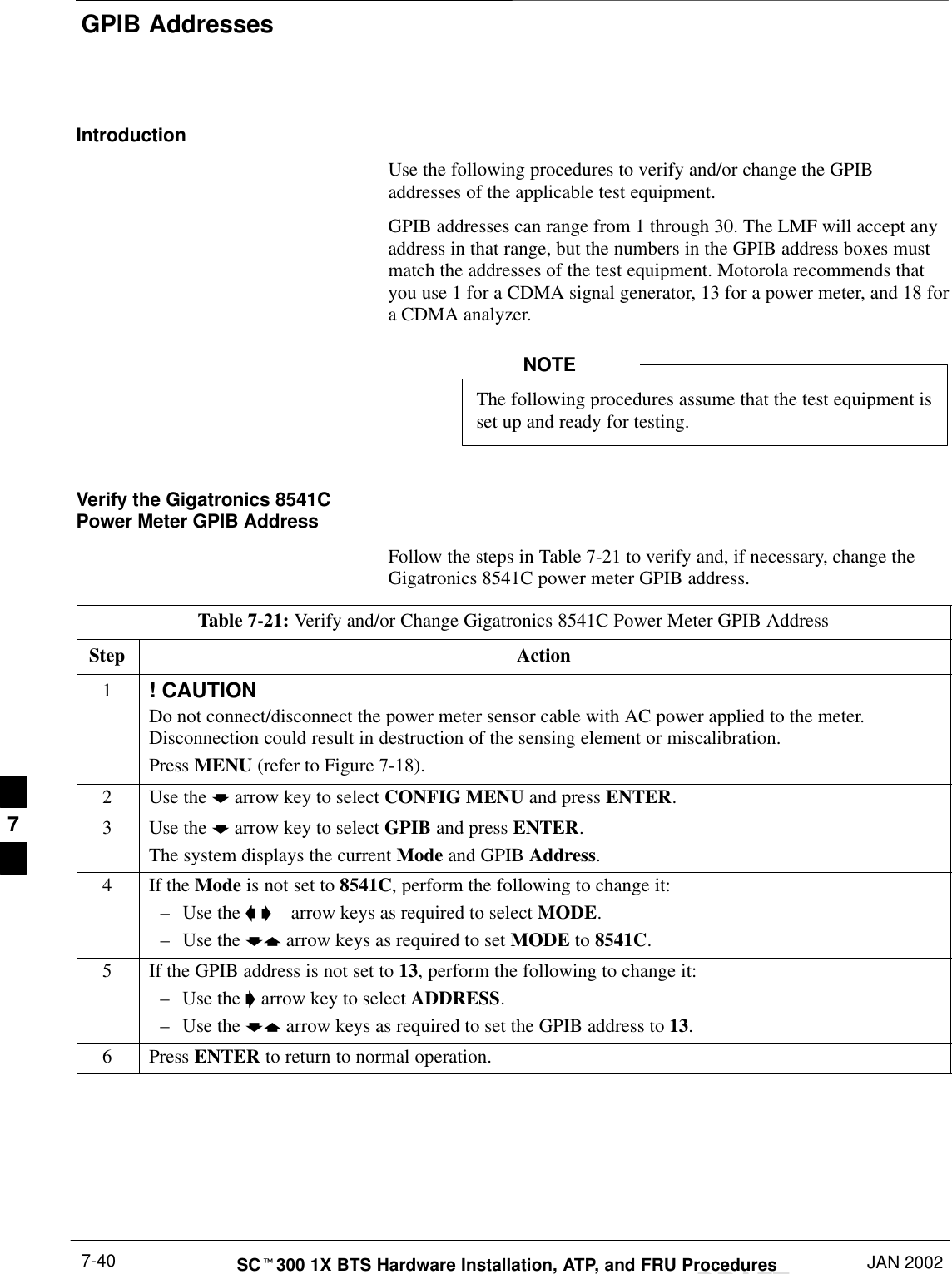
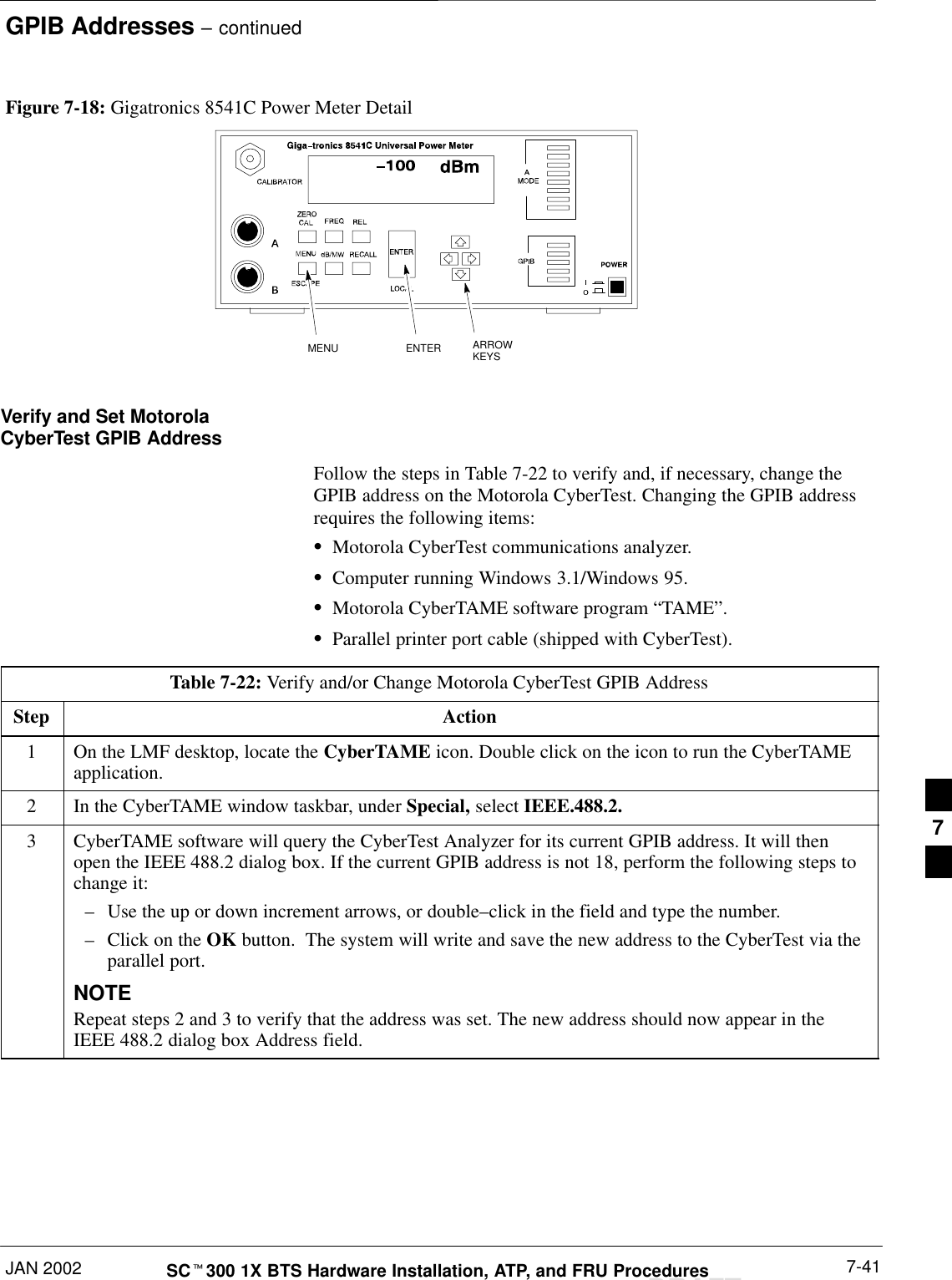
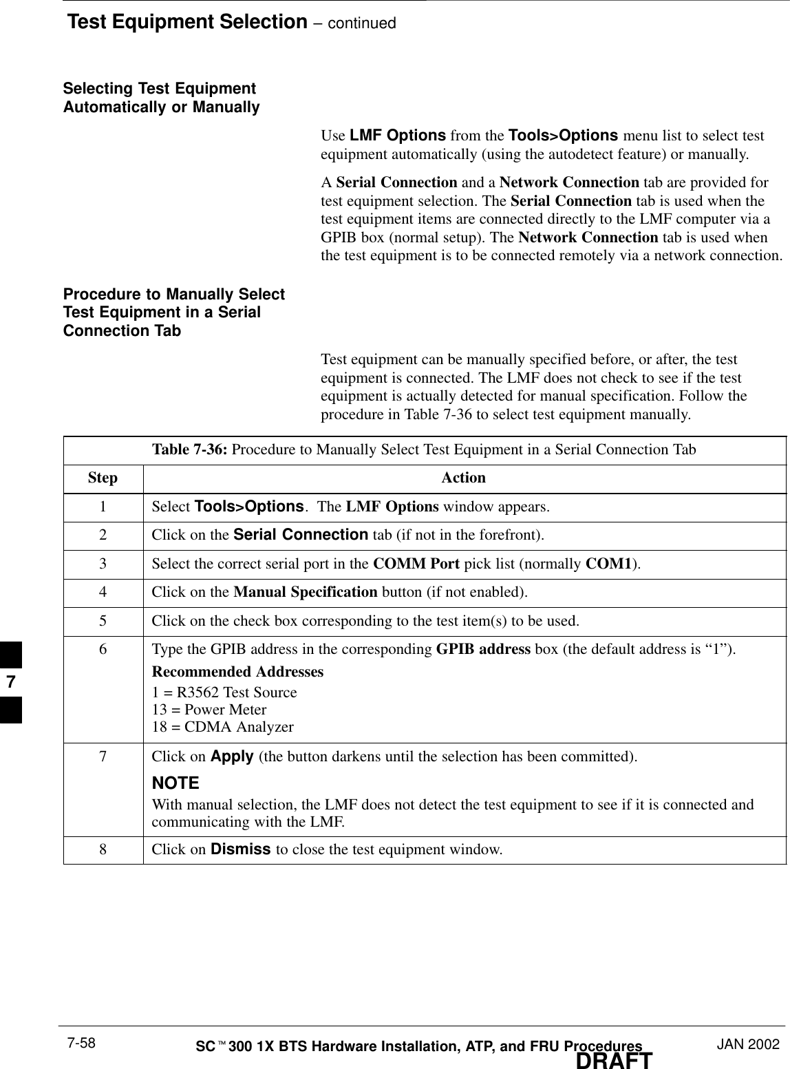
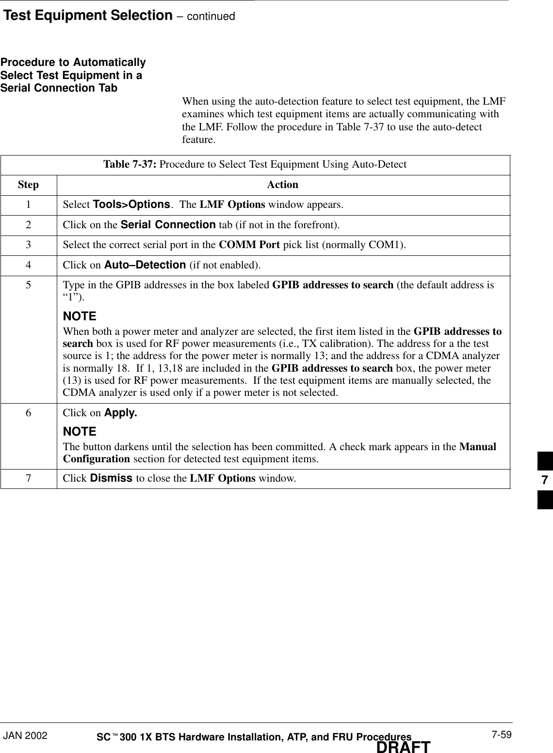
GPIB AddressesDRAFTSCt300 1X BTS Hardware Installation, ATP, and FRU Procedures JAN 20027-40IntroductionUse the following procedures to verify and/or change the GPIBaddresses of the applicable test equipment.GPIB addresses can range from 1 through 30. The LMF will accept anyaddress in that range, but the numbers in the GPIB address boxes mustmatch the addresses of the test equipment. Motorola recommends thatyou use 1 for a CDMA signal generator, 13 for a power meter, and 18 fora CDMA analyzer.The following procedures assume that the test equipment isset up and ready for testing.NOTEVerify the Gigatronics 8541CPower Meter GPIB AddressFollow the steps in Table 7-21 to verify and, if necessary, change theGigatronics 8541C power meter GPIB address.Table 7-21: Verify and/or Change Gigatronics 8541C Power Meter GPIB AddressStep Action1! CAUTIONDo not connect/disconnect the power meter sensor cable with AC power applied to the meter.Disconnection could result in destruction of the sensing element or miscalibration.Press MENU (refer to Figure 7-18).2Use the b arrow key to select CONFIG MENU and press ENTER.3Use the b arrow key to select GPIB and press ENTER.The system displays the current Mode and GPIB Address.4If the Mode is not set to 8541C, perform the following to change it:–Use the a '  arrow keys as required to select MODE.–Use the by arrow keys as required to set MODE to 8541C.5If the GPIB address is not set to 13, perform the following to change it:–Use the ' arrow key to select ADDRESS.–Use the by arrow keys as required to set the GPIB address to 13.6 Press ENTER to return to normal operation.7
GPIB Addresses – continuedJAN 2002 7-41SCt300 1X BTS Hardware Installation, ATP, and FRU ProceduresDRAFTMENU ENTER ARROWKEYS1Figure 7-18: Gigatronics 8541C Power Meter DetailVerify and Set MotorolaCyberTest GPIB AddressFollow the steps in Table 7-22 to verify and, if necessary, change theGPIB address on the Motorola CyberTest. Changing the GPIB addressrequires the following items:SMotorola CyberTest communications analyzer.SComputer running Windows 3.1/Windows 95.SMotorola CyberTAME software program “TAME”.SParallel printer port cable (shipped with CyberTest).Table 7-22: Verify and/or Change Motorola CyberTest GPIB AddressStep Action1On the LMF desktop, locate the CyberTAME icon. Double click on the icon to run the CyberTAMEapplication.2In the CyberTAME window taskbar, under Special, select IEEE.488.2.3CyberTAME software will query the CyberTest Analyzer for its current GPIB address. It will thenopen the IEEE 488.2 dialog box. If the current GPIB address is not 18, perform the following steps tochange it:–Use the up or down increment arrows, or double–click in the field and type the number.–Click on the OK button.  The system will write and save the new address to the CyberTest via theparallel port.NOTERepeat steps 2 and 3 to verify that the address was set. The new address should now appear in theIEEE 488.2 dialog box Address field.7
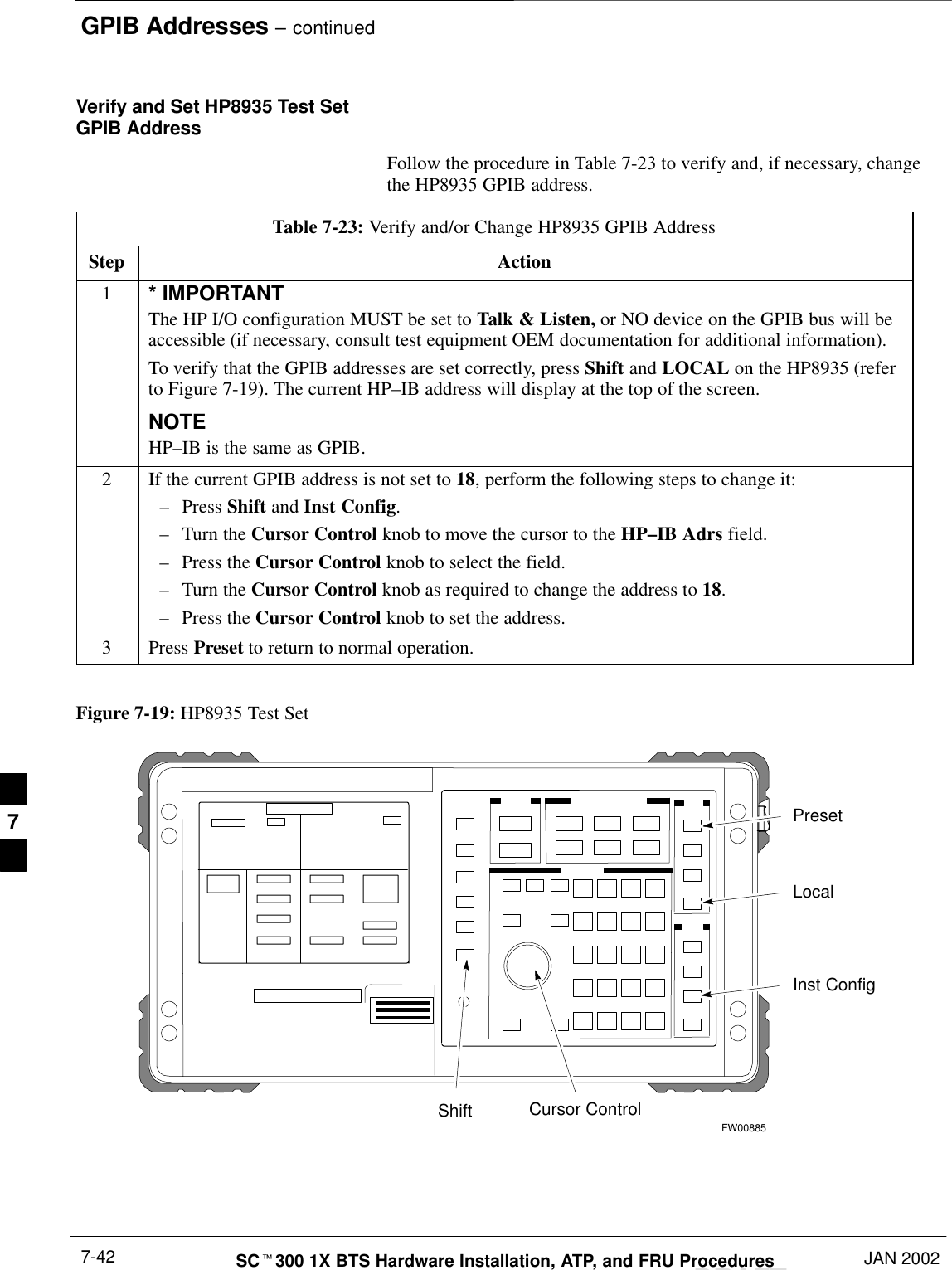
GPIB Addresses – continuedDRAFTSCt300 1X BTS Hardware Installation, ATP, and FRU Procedures JAN 20027-42Verify and Set HP8935 Test SetGPIB AddressFollow the procedure in Table 7-23 to verify and, if necessary, changethe HP8935 GPIB address.Table 7-23: Verify and/or Change HP8935 GPIB AddressStep Action1* IMPORTANTThe HP I/O configuration MUST be set to Talk & Listen, or NO device on the GPIB bus will beaccessible (if necessary, consult test equipment OEM documentation for additional information).To verify that the GPIB addresses are set correctly, press Shift and LOCAL on the HP8935 (referto Figure 7-19). The current HP–IB address will display at the top of the screen.NOTEHP–IB is the same as GPIB.2If the current GPIB address is not set to 18, perform the following steps to change it:–Press Shift and Inst Config.–Turn the Cursor Control knob to move the cursor to the HP–IB Adrs field.–Press the Cursor Control knob to select the field.–Turn the Cursor Control knob as required to change the address to 18.–Press the Cursor Control knob to set the address.3 Press Preset to return to normal operation. Figure 7-19: HP8935 Test SetFW00885PresetCursor ControlShiftInst ConfigLocal7
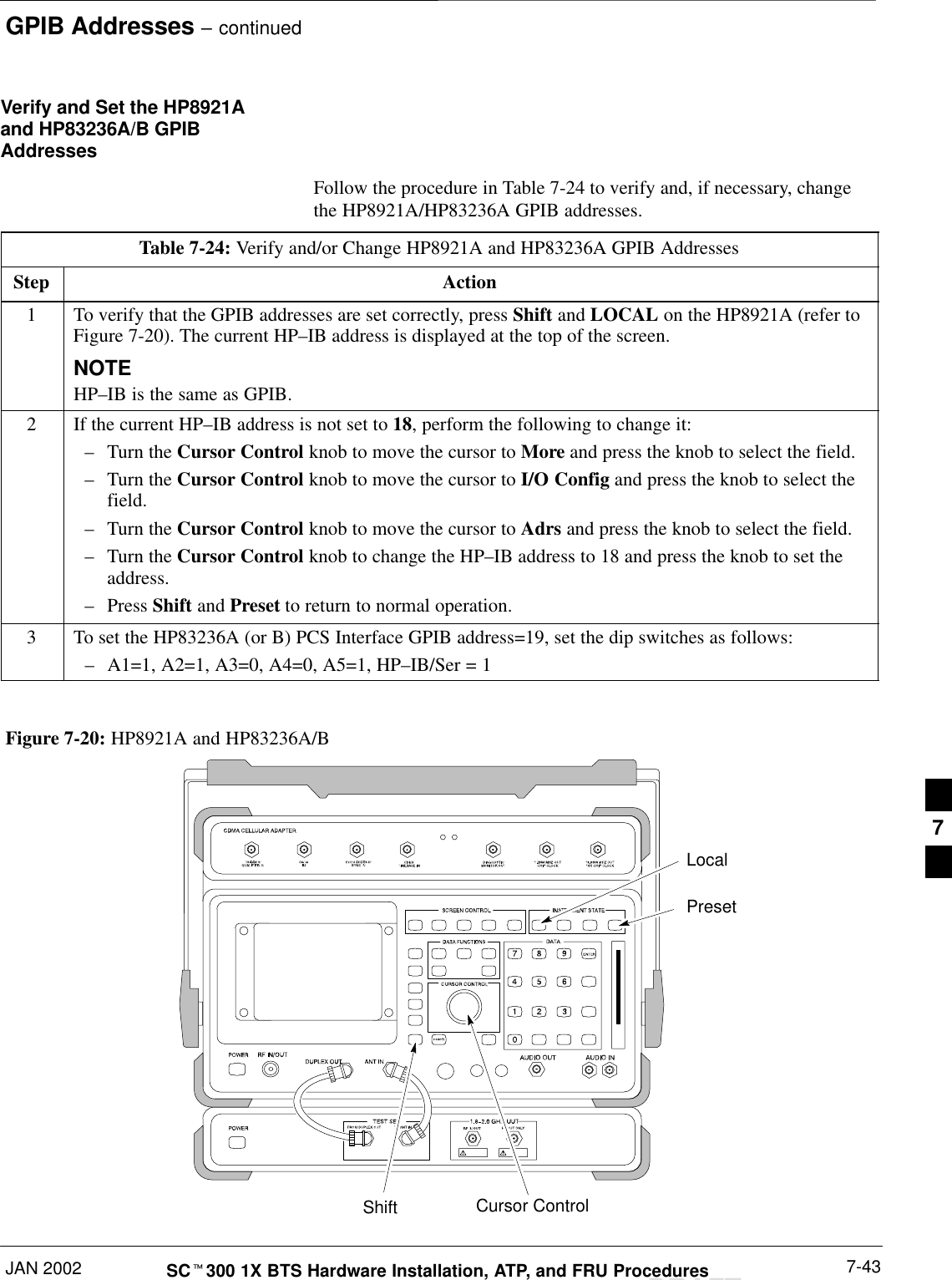
GPIB Addresses – continuedJAN 2002 7-43SCt300 1X BTS Hardware Installation, ATP, and FRU ProceduresDRAFTVerify and Set the HP8921Aand HP83236A/B GPIBAddressesFollow the procedure in Table 7-24 to verify and, if necessary, changethe HP8921A/HP83236A GPIB addresses.Table 7-24: Verify and/or Change HP8921A and HP83236A GPIB AddressesStep Action1To verify that the GPIB addresses are set correctly, press Shift and LOCAL on the HP8921A (refer toFigure 7-20). The current HP–IB address is displayed at the top of the screen.NOTEHP–IB is the same as GPIB.2If the current HP–IB address is not set to 18, perform the following to change it:–Turn the Cursor Control knob to move the cursor to More and press the knob to select the field.–Turn the Cursor Control knob to move the cursor to I/O Config and press the knob to select thefield.–Turn the Cursor Control knob to move the cursor to Adrs and press the knob to select the field.–Turn the Cursor Control knob to change the HP–IB address to 18 and press the knob to set theaddress.–Press Shift and Preset to return to normal operation.3To set the HP83236A (or B) PCS Interface GPIB address=19, set the dip switches as follows:–A1=1, A2=1, A3=0, A4=0, A5=1, HP–IB/Ser = 1PresetCursor ControlShiftLocalFigure 7-20: HP8921A and HP83236A/B7
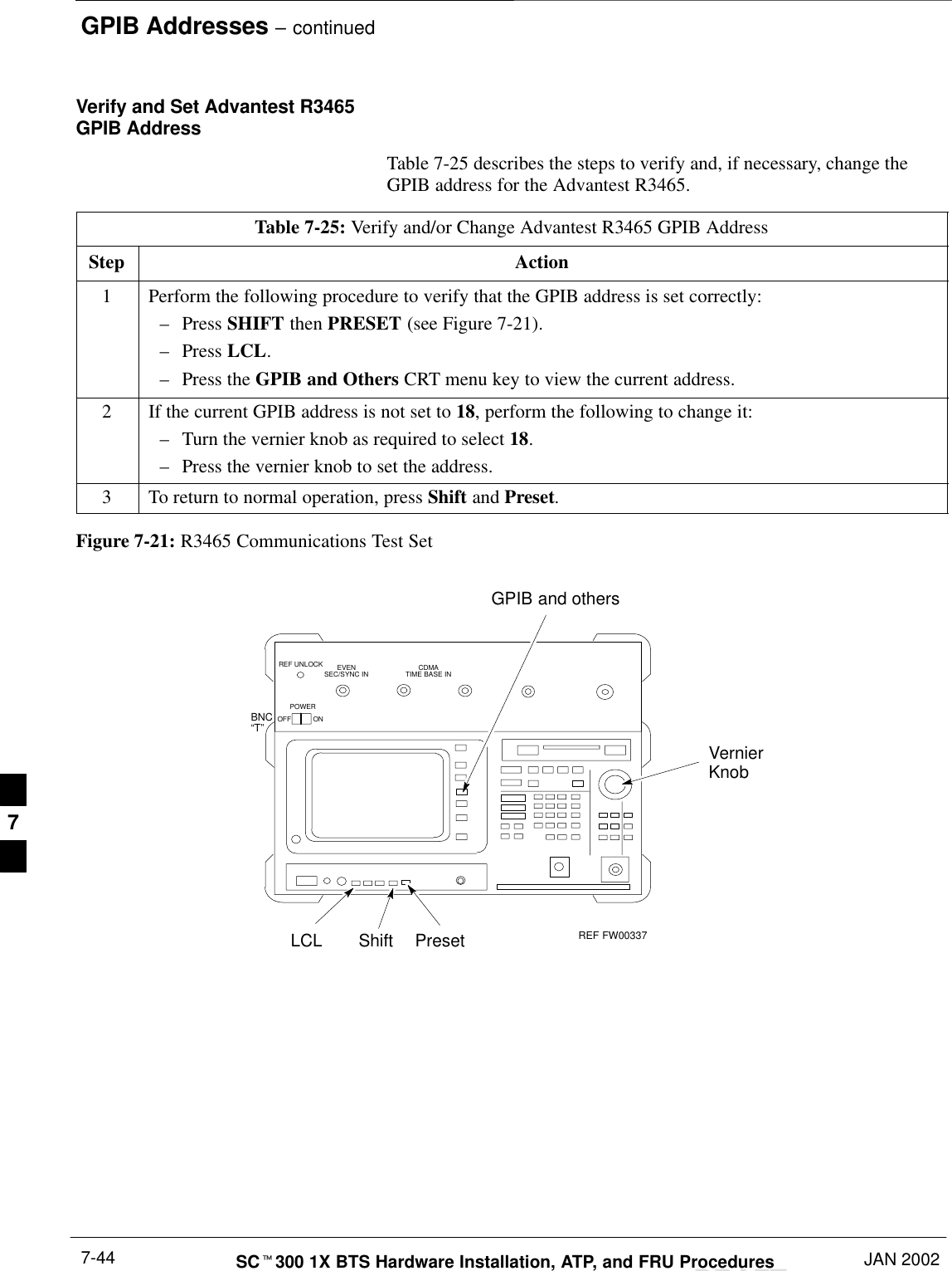
GPIB Addresses – continuedDRAFTSCt300 1X BTS Hardware Installation, ATP, and FRU Procedures JAN 20027-44Verify and Set Advantest R3465GPIB AddressTable 7-25 describes the steps to verify and, if necessary, change theGPIB address for the Advantest R3465.Table 7-25: Verify and/or Change Advantest R3465 GPIB AddressStep Action1Perform the following procedure to verify that the GPIB address is set correctly:–Press SHIFT then PRESET (see Figure 7-21).–Press LCL.–Press the GPIB and Others CRT menu key to view the current address.2If the current GPIB address is not set to 18, perform the following to change it:–Turn the vernier knob as required to select 18.–Press the vernier knob to set the address.3To return to normal operation, press Shift and Preset.Figure 7-21: R3465 Communications Test SetBNC“T”REF UNLOCK EVENSEC/SYNC IN CDMATIME BASE INPOWEROFF ONREF FW00337LCL Shift PresetGPIB and othersVernierKnob7
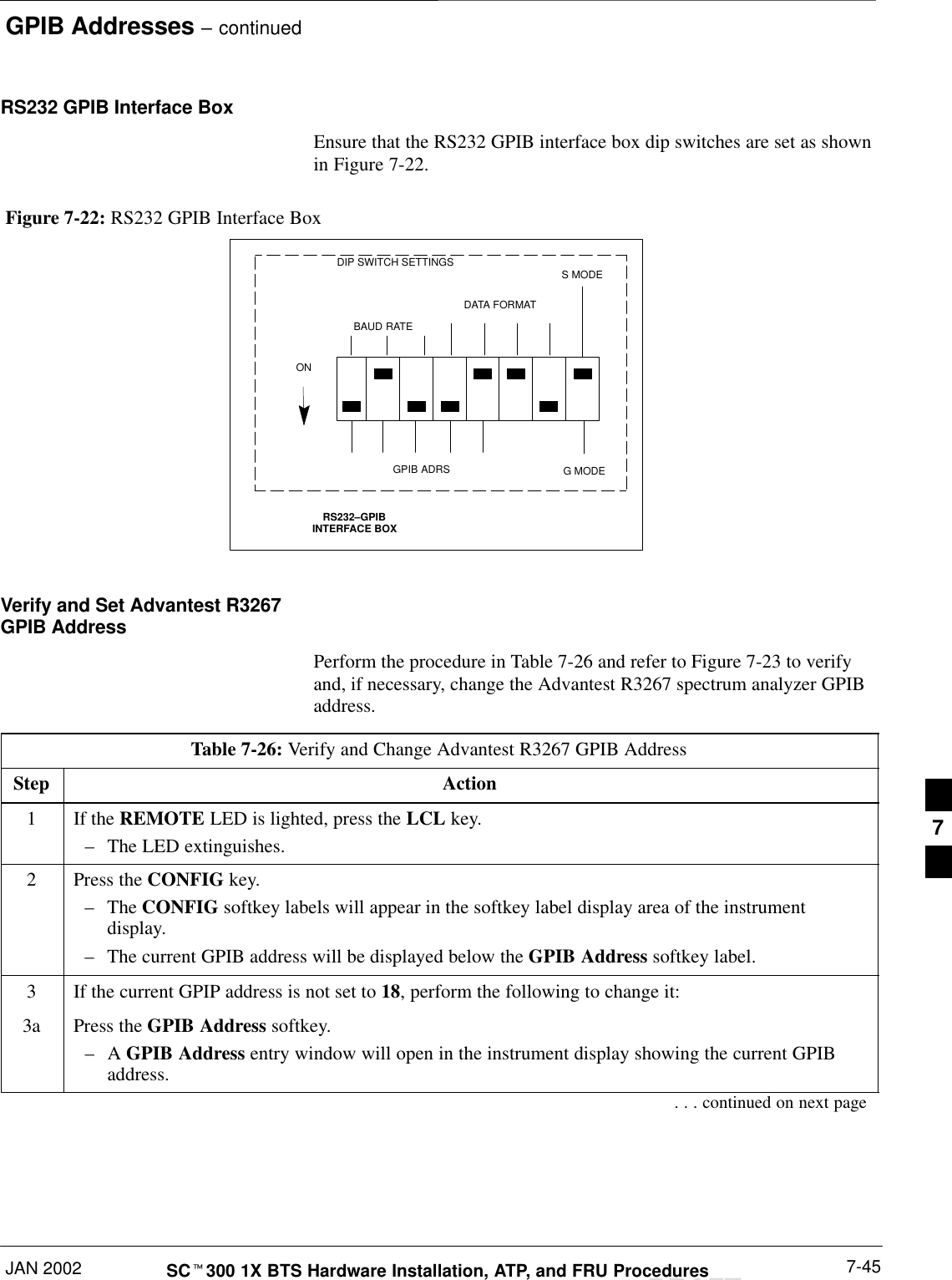
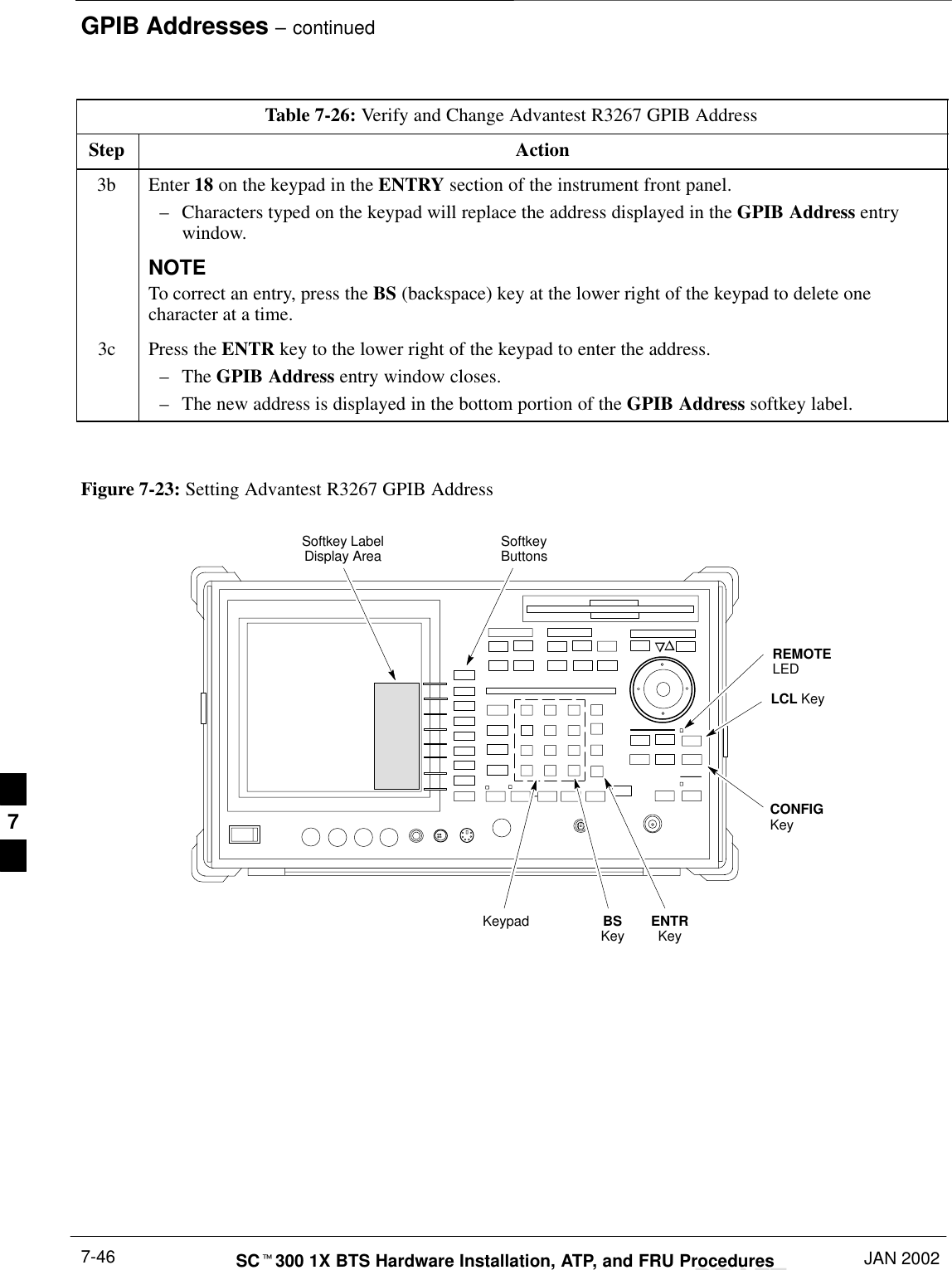
GPIB Addresses – continuedJAN 2002 7-45SCt300 1X BTS Hardware Installation, ATP, and FRU ProceduresDRAFTRS232 GPIB Interface BoxEnsure that the RS232 GPIB interface box dip switches are set as shownin Figure 7-22.RS232–GPIBINTERFACE BOXS MODEDATA FORMATBAUD RATEGPIB ADRSONDIP SWITCH SETTINGSG MODEFigure 7-22: RS232 GPIB Interface BoxVerify and Set Advantest R3267GPIB AddressPerform the procedure in Table 7-26 and refer to Figure 7-23 to verifyand, if necessary, change the Advantest R3267 spectrum analyzer GPIBaddress.Table 7-26: Verify and Change Advantest R3267 GPIB AddressStep Action1If the REMOTE LED is lighted, press the LCL key.–The LED extinguishes.2Press the CONFIG key.–The CONFIG softkey labels will appear in the softkey label display area of the instrumentdisplay.–The current GPIB address will be displayed below the GPIB Address softkey label.3If the current GPIP address is not set to 18, perform the following to change it:3a Press the GPIB Address softkey.–A GPIB Address entry window will open in the instrument display showing the current GPIBaddress.. . . continued on next page7
GPIB Addresses – continuedDRAFTSCt300 1X BTS Hardware Installation, ATP, and FRU Procedures JAN 20027-46Table 7-26: Verify and Change Advantest R3267 GPIB AddressStep Action3b Enter 18 on the keypad in the ENTRY section of the instrument front panel.–Characters typed on the keypad will replace the address displayed in the GPIB Address entrywindow.NOTETo correct an entry, press the BS (backspace) key at the lower right of the keypad to delete onecharacter at a time.3c Press the ENTR key to the lower right of the keypad to enter the address.–The GPIB Address entry window closes.–The new address is displayed in the bottom portion of the GPIB Address softkey label. Figure 7-23: Setting Advantest R3267 GPIB AddressonREMOTELEDLCL KeyCONFIGKeySoftkey LabelDisplay Area SoftkeyButtonsKeypad BSKey ENTRKey7
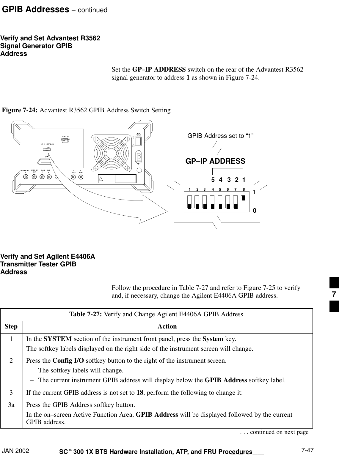
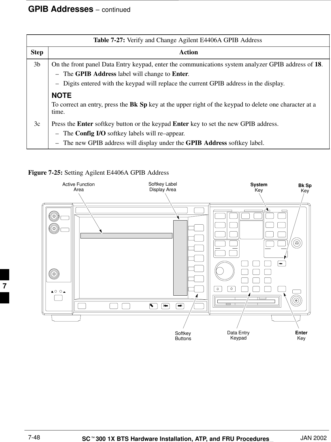
GPIB Addresses – continuedJAN 2002 7-47SCt300 1X BTS Hardware Installation, ATP, and FRU ProceduresDRAFTVerify and Set Advantest R3562Signal Generator GPIBAddressSet the GP–IP ADDRESS switch on the rear of the Advantest R3562signal generator to address 1 as shown in Figure 7-24.Figure 7-24: Advantest R3562 GPIB Address Switch Setting123 4567854321GP–IP ADDRESS10GPIB Address set to “1”Verify and Set Agilent E4406ATransmitter Tester GPIBAddressFollow the procedure in Table 7-27 and refer to Figure 7-25 to verifyand, if necessary, change the Agilent E4406A GPIB address.Table 7-27: Verify and Change Agilent E4406A GPIB AddressStep Action1In the SYSTEM section of the instrument front panel, press the System key.The softkey labels displayed on the right side of the instrument screen will change.2Press the Config I/O softkey button to the right of the instrument screen.–The softkey labels will change.–The current instrument GPIB address will display below the GPIB Address softkey label.3If the current GPIB address is not set to 18, perform the following to change it:3a Press the GPIB Address softkey button.In the on–screen Active Function Area, GPIB Address will be displayed followed by the currentGPIB address.. . . continued on next page7
GPIB Addresses – continuedDRAFTSCt300 1X BTS Hardware Installation, ATP, and FRU Procedures JAN 20027-48Table 7-27: Verify and Change Agilent E4406A GPIB AddressStep Action3b On the front panel Data Entry keypad, enter the communications system analyzer GPIB address of 18.–The GPIB Address label will change to Enter.–Digits entered with the keypad will replace the current GPIB address in the display.NOTETo correct an entry, press the Bk Sp key at the upper right of the keypad to delete one character at atime.3c Press the Enter softkey button or the keypad Enter key to set the new GPIB address.–The Config I/O softkey labels will re–appear.–The new GPIB address will display under the GPIB Address softkey label. Figure 7-25: Setting Agilent E4406A GPIB AddressSystemKey Bk SpKeyEnterKeyData EntryKeypadSoftkeyButtonsSoftkey LabelDisplay AreaActive FunctionArea7
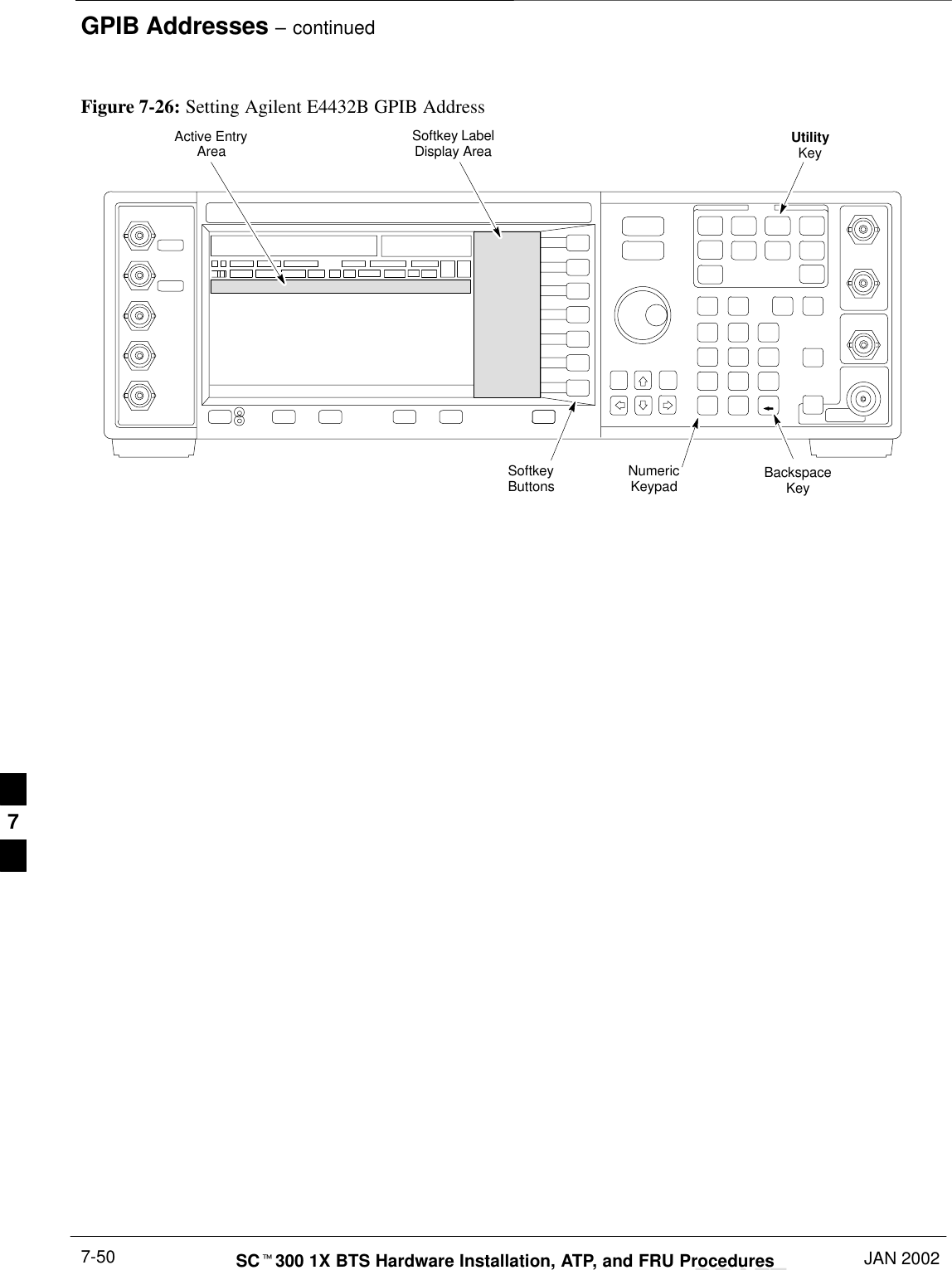
GPIB Addresses – continuedJAN 2002 7-49SCt300 1X BTS Hardware Installation, ATP, and FRU ProceduresDRAFTVerify and Set Agilent E4432BSignal Generator GPIBAddressRefer to Figure 7-26 and follow the procedure in Table 7-28 to verifyand, if necessary, change the Agilent E4432B GPIB address.Table 7-28: Verify and Change Agilent E4432B GPIB AddressStep Action1In the MENUS section of the instrument front panel, press the Utility key.–The softkey labels displayed on the right side of the instrument screen will change.2Press the GPIB/RS232 softkey button to the right of the instrument screen.–The softkey labels will change.–The current instrument GPIB address will be display below the GPIB Address softkey label.3If the current GPIB address is not set to 1, perform the following to change it:3a Press the GPIB Address softkey button.–The GPIB Address label and current GPIB address will change to boldface.–In the on–screen Active Entry Area, Address: and the current GPIB address will display.3b On the front panel Numeric keypad, enter the signal generator GPIB address of 1.–The GPIB Address label will change to Enter.–Digits entered with the keypad will replace the current GPIB address in the Active Entry display.NOTETo correct an entry, press the backspace key at the lower right of the keypad to delete one character ata time.3c Press the Enter softkey button to set the new GPIB address.–The new GPIB address will be display under the GPIB Address softkey label. 7
GPIB Addresses – continuedDRAFTSCt300 1X BTS Hardware Installation, ATP, and FRU Procedures JAN 20027-50Figure 7-26: Setting Agilent E4432B GPIB AddressNumericKeypadSoftkeyButtonsSoftkey LabelDisplay AreaActive EntryAreaBackspaceKeyUtilityKey7
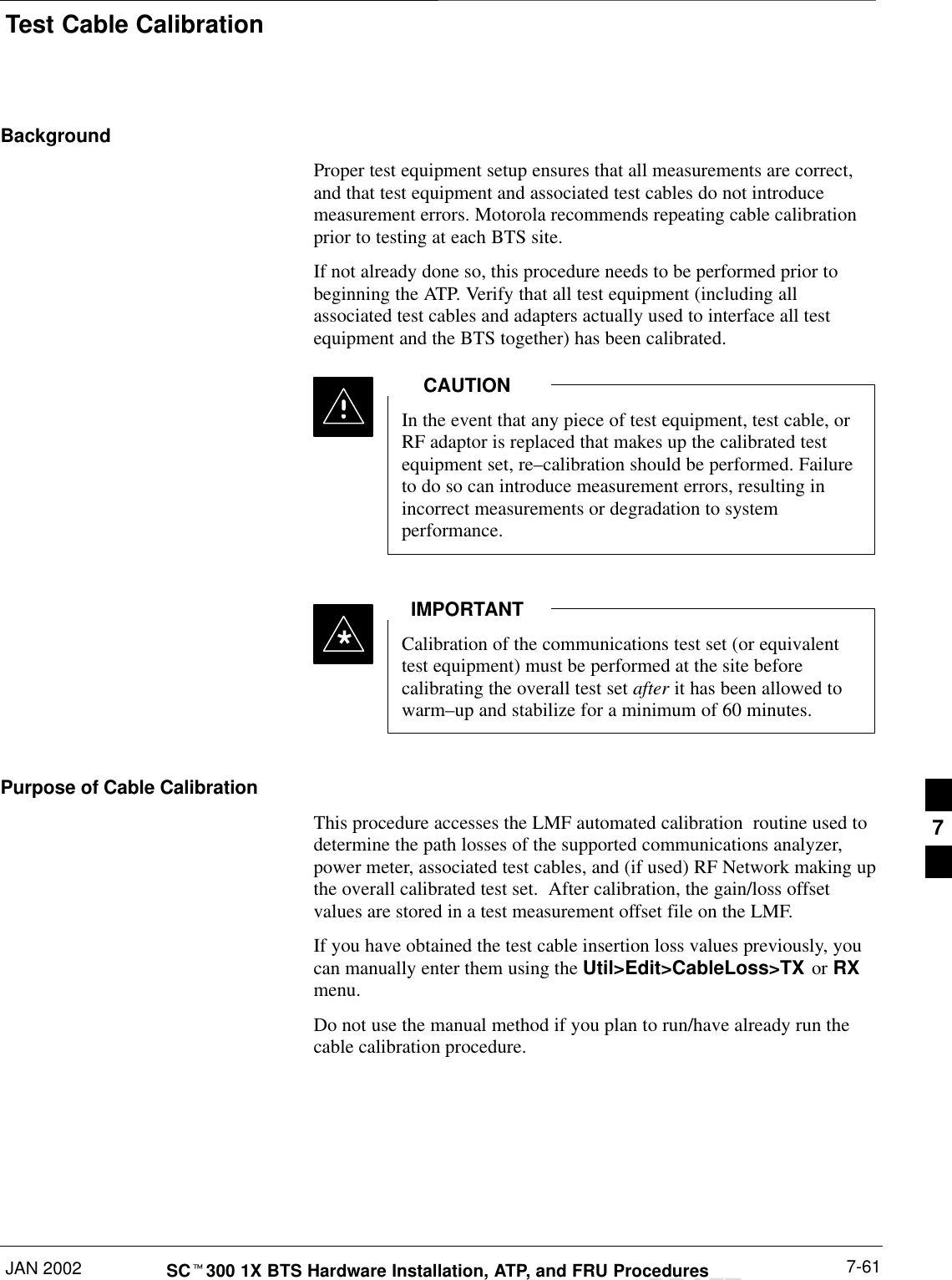
Test Equipment CalibrationJAN 2002 7-51SCt300 1X BTS Hardware Installation, ATP, and FRU ProceduresDRAFTBackgroundTo prevent damage to the test equipment, all Microcelltransmit (TX) tests must be made using the 30 dBattenuator.CAUTIONProper test equipment calibration ensures that the test equipment andassociated test cables do not introduce measurement errors, and thatmeasurements are correct.If the test set being used to interface with the BTS has beencalibrated and maintained as a set, this procedure does notneed to be performed. (Test Set includes LMF terminal,communications test set, additional test equipment,associated test cables, and adapters.)NOTEThis procedure must be performed prior to beginning the optimization.Verify all test equipment (including all associated test cables andadapters actually used to interface all test equipment and the BTS) hasbeen calibrated and maintained as a set.If any piece of test equipment, test cable, or RF adapter,that makes up the calibrated test equipment set, has beenreplaced, re-calibration must be performed. Failure to do socan introduce measurement errors, resulting in incorrectmeasurements and degradation to system performance.CAUTIONCalibration of the communications test set (or equivalenttest equipment) must be performed at the site beforecalibrating the overall test set. Calibrate the test equipmentafter it has been allowed to warm–up and stabilize for aminimum of 60 minutes.IMPORTANT*These procedures access the LMF automated calibration routine used todetermine the path losses of the supported communications analyzer,power meter, associated test cables, and (if used) antenna switch thatmake up the overall calibrated test set. After calibration, the gain/lossoffset values are stored in a test measurement offset file on the LMF.7
Test Equipment Calibration – continuedDRAFTSCt300 1X BTS Hardware Installation, ATP, and FRU Procedures JAN 20027-52Procedure to Calibrate TestEquipmentThe calibrate test equipment function zeros the power measurement levelof the test equipment item that is to be used for TX calibration and audit.If both a power meter and an analyzer are connected, only the powermeter is zeroed.Use the Calibrate Test Equipment menu item from the Util menu tocalibrate test equipment. The test equipment must be selected beforecalibration can begin. Follow the procedure in Table 7-29 to calibrate thetest equipment.PrerequisitesEnsure the following prerequisites have been met before proceeding:STest equipment to be calibrated has been connected correctly for teststhat are to be run.STest equipment has been selected.Table 7-29: Procedure to Calibrate Test EquipmentStep Action1From the Util menu, select Calibrate Test Equipment.A Directions window is displayed.2Follow the directions provided.3Click on Continue to close the Directions window.A status report window is displayed.4Click on OK to close the status report window.Calibration Without the LMFSeveral test equipment items used in the optimization process requirepre–calibration actions or calibration verification which are notsupported by the LMF. Procedures to perform these activities for theapplicable test equipment items are covered in this section.7
Test Equipment Calibration – continuedJAN 2002 7-53SCt300 1X BTS Hardware Installation, ATP, and FRU ProceduresDRAFTProcedure to Calibrate R3465Test SetFollow the steps inTable 7-30 to configure and calibrate the R3465communication test set.Table 7-30: Procedure to Calibrate R3465Step Action1* IMPORTANT–Perform this calibration only after the analyzer has warmed–up and stabilized for a minimumof 60 minutes.  Test equipment warm–up may vary depending on operating environment orinitial temperature of unit upon turn–on. Consult test equipment OEM documentation foradditional information as required.Connect the male BNC to male N cable between the CAL OUT connector and the INPUT 50 Wconnector.2 Select CW.3Push the SHIFT and CAL pushbuttons.4 Select Cal All in CRT menu.Internal calibration should complete in about 6 minutes.Procedure to Calibrate R3267Test SetFollow the steps in Table 7-31 to configure and calibrate the R3267communication test set.Table 7-31: Procedure to Calibrate R3267Step Action1* IMPORTANT–Perform this calibration only after the analyzer has warmed–up and stabilized for a minimumof 60 minutes.  Test equipment warm–up may vary depending on operating environment orinitial temperature of unit upon turn–on. Consult test equipment OEM documentation foradditional information as required.Connect the male BNC to male N cable between the CAL OUT connector and the INPUT 50 Wconnector.2 Select CW.3Push the SHIFT and CAL pushbuttons.4 Select Cal All in CRT menu.Internal calibration should complete in about 6 minutes.7
Test Equipment Calibration – continuedDRAFTSCt300 1X BTS Hardware Installation, ATP, and FRU Procedures JAN 20027-54Procedure to Calibrate AgilentE4406ARefer to Figure 7-27 and follow the procedure in Table 7-32 to performthe Agilent E4406A self–alignment (calibration).Table 7-32: Perform Agilent E4406A Self–alignment (Calibration)Step Action1In the SYSTEM section of the instrument front panel, press the System key.–The softkey labels displayed on the right side of the instrument screen will change.2Press the Alignments softkey button to the right of the instrument screen.–The softkey labels will change.3Press the Align All Now softkey button.–All other instrument functions will be suspended during the alignment.–The display will change to show progress and results of the alignments performed.–The alignment will take less than one minute. Figure 7-27: Performing Agilent E4406A Self–alignment (Calibration)SystemKeySoftkeyButtonsSoftkey LabelDisplay Area7
Test Equipment Calibration – continuedJAN 2002 7-55SCt300 1X BTS Hardware Installation, ATP, and FRU ProceduresDRAFTProcedure to Setup AdvantestR3465 Test EquipmentFollow the steps outlined in Table 7-33 (for Advantest R3465) orTable 7-34 (for Advantest R3267) to set up test equipment prior toperforming ATP tests.LMF based measurements factor in cable and attenuatorloss between the BTS and test equipment. No additionalattenuation can be inserted as the additional losses wouldnot be factored in.IMPORTANT*If you are logged in to the BTS, you must log out prior toloading the special JCDMA software on a PCMCIA RAMcard and inserting it in the Advantest R3465 PCMCIA slot.This must be done before using the Advantest R3465 testset for JCDMA tests.IMPORTANT*Table 7-33: Procedure to Setup Advantest R3465 Test  EquipmentStep Action1If you have not already done so, interface the CDMA LMF computer to the BTS and login to the BTS.2Perform the following steps  for the manual test procedure for Automated TX verification.Set up the communication test set by inserting the Automatic TX test PCMCIA card into theAdvantest PCMCIA card reader slot A. (software version=97.10.07 rev 0001 or later).Perform the following steps to access and use the Advantest Automatic TX test screen:3Press the Remote LCL button (located below the CRT).4Press the Loader ON button (located below the CRT).5Press the LOAD CRT menu button.6Use the DISPLAY CONTROL knob to select CDMA_BSR.BAS and then press the knob.7Press the RUN CRT menu button after the LOAD pop–up disappears.8Wait for *Idle Free space to appear at the bottom of the CRT.9Refer to Figure 7-34 to set up test equipment.Verify that the coaxial cable from the appropriate TX connector on the BTS is connected to the testequipment RF input port via the in line 30 dB high power attenuator for MicroCell BTSs.7
Test Equipment Calibration – continuedDRAFTSCt300 1X BTS Hardware Installation, ATP, and FRU Procedures JAN 20027-56Procedure to Setup AdvantestR3267 Test EquipmentTable 7-34: Procedure to Setup Advantest R3267 Test  EquipmentStep Action1If you have not already done so, interface the CDMA LMF computer to the BTS and login to the BTS.2Perform the following steps for the manual test procedure for Automated TX verification.Set up the communication test set by inserting the Automatic TX test PCMCIA card into theAdvantest PCMCIA card reader slot A. (software revision 0.0.0.4 or later).Perform the following steps to access and use the Advantest Automatic TX test screen:3Press the Remote LCL button (located below the CRT).4Press the Loader ON button (located below the CRT).5 Select LOAD on the CRT screen (button #6).6Use the DISPLAY CONTROL knob to select the REMOTE.BAS file, then press the knob.7 Select RUN on the CRT screen (button #1).8Wait for *Idle Free space to appear at the bottom of the CRT.9Refer to Figure 7-34 to set up test equipment.Verify that the coaxial cable from the appropriate TX connector on the BTS is connected to the testequipment RF input port via the in line 30 dB high power attenuator for MicroCell BTSs.7
Test Equipment SelectionJAN 2002 7-57SCt300 1X BTS Hardware Installation, ATP, and FRU ProceduresDRAFTObjectiveThe objective of this procedure is to select the test equipment used forBTS testing.  The LMF must select the test equipment before it is usedfor BTS testing.PrerequisitesThe following are prerequisites for test equipment selection:1. Test equipment to be used has been connected as shown inFigure 7-16.2. Power for the test equipment and GPIB box has been turned on.3. LMF has been started (do not have to be logged in to the BTS).Procedure to Select TestEquipmentFollow the steps in Table 7-35 for test equipment selectionThe test equipment can also be selected via a manual orautomatic connection.  Refer to the CDMA LMFOperator’s Guide, 68P64114A78 for the procedures.NOTETable 7-35: Procedure to Select Test EquipmentStep Action1 Select Tools>Options from the menu.  A LMF Options window appears.2Select the correct COM port from the Comm Port pick list (normally COM1).3Click on the Auto–Detection button if it is not enabled.4If the GPIB addresses are not displayed, enter the GPIB addresses in the box labeled GPIBaddresses to search.NOTEWhen both a power meter and a communication test set are selected, the first item listed in theGPIB addresses to search box will be used for RF power measurements, e.g., TX calibration andaudit.  The address for a power meter is 13 and the address for a communications test set is  18.The numbers 13 and 18 must be included in the GPIB address to search box so the power meter(13) will be used for TX calibration and audit.5Click on the Apply button.  The button will darken until the selection has been committed.  Acheck mark will appear in the Manual Configuration section for detected test equipment items.6Click on the Dismiss button to close the LMF Options window.7
Test Equipment Selection – continuedDRAFTSCt300 1X BTS Hardware Installation, ATP, and FRU Procedures JAN 20027-58Selecting Test EquipmentAutomatically or ManuallyUse LMF Options from the Tools>Options menu list to select testequipment automatically (using the autodetect feature) or manually.A Serial Connection and a Network Connection tab are provided fortest equipment selection. The Serial Connection tab is used when thetest equipment items are connected directly to the LMF computer via aGPIB box (normal setup). The Network Connection tab is used whenthe test equipment is to be connected remotely via a network connection.Procedure to Manually SelectTest Equipment in a SerialConnection TabTest equipment can be manually specified before, or after, the testequipment is connected. The LMF does not check to see if the testequipment is actually detected for manual specification. Follow theprocedure in Table 7-36 to select test equipment manually.Table 7-36: Procedure to Manually Select Test Equipment in a Serial Connection TabStep Action1 Select Tools>Options.  The LMF Options window appears.2Click on the Serial Connection tab (if not in the forefront).3Select the correct serial port in the COMM Port pick list (normally COM1).4Click on the Manual Specification button (if not enabled).5Click on the check box corresponding to the test item(s) to be used.6Type the GPIB address in the corresponding GPIB address box (the default address is “1”).Recommended Addresses1 = R3562 Test Source13 = Power Meter18 = CDMA Analyzer7Click on Apply (the button darkens until the selection has been committed).NOTEWith manual selection, the LMF does not detect the test equipment to see if it is connected andcommunicating with the LMF.8Click on Dismiss to close the test equipment window.7
Test Equipment Selection – continuedJAN 2002 7-59SCt300 1X BTS Hardware Installation, ATP, and FRU ProceduresDRAFTProcedure to AutomaticallySelect Test Equipment in aSerial Connection Tab When using the auto-detection feature to select test equipment, the LMFexamines which test equipment items are actually communicating withthe LMF. Follow the procedure in Table 7-37 to use the auto-detectfeature.Table 7-37: Procedure to Select Test Equipment Using Auto-DetectStep Action1 Select Tools>Options.  The LMF Options window appears.2Click on the Serial Connection tab (if not in the forefront).3Select the correct serial port in the COMM Port pick list (normally COM1).4Click on Auto–Detection (if not enabled).5Type in the GPIB addresses in the box labeled GPIB addresses to search (the default address is“1”).NOTEWhen both a power meter and analyzer are selected, the first item listed in the GPIB addresses tosearch box is used for RF power measurements (i.e., TX calibration). The address for a the testsource is 1; the address for the power meter is normally 13; and the address for a CDMA analyzeris normally 18.  If 1, 13,18 are included in the GPIB addresses to search box, the power meter(13) is used for RF power measurements.  If the test equipment items are manually selected, theCDMA analyzer is used only if a power meter is not selected.6Click on Apply.NOTEThe button darkens until the selection has been committed. A check mark appears in the ManualConfiguration section for detected test equipment items.7 Click Dismiss to close the LMF Options window. 7
Power Meter CalibrationDRAFTSCt300 1X BTS Hardware Installation, ATP, and FRU Procedures JAN 20027-60ObjectiveThis procedure calibrates the power meter that will be used for cablecalibration and BTS testing.PrerequisitesThe following are prerequisites for power meter calibration:1. The power meter is connected.  Refer to Figure 7-16 in the “TestEquipment Selection” procedure.2. Test equipment has been selected.Procedure to Calibrate thePower MeterFollow the steps in Table 7-38 to calibrate the power meter.Table 7-38: Procedure to Calibrate the Power MeterStep Action1Click on  Util>Calibrate Test Equipment.  A cable connection direction pop–up is displayed.2Follow the directions provided.3Click on the OK button to close the status results window.7
Test Cable CalibrationJAN 2002 7-61SCt300 1X BTS Hardware Installation, ATP, and FRU ProceduresDRAFTBackgroundProper test equipment setup ensures that all measurements are correct,and that test equipment and associated test cables do not introducemeasurement errors. Motorola recommends repeating cable calibrationprior to testing at each BTS site.If not already done so, this procedure needs to be performed prior tobeginning the ATP. Verify that all test equipment (including allassociated test cables and adapters actually used to interface all testequipment and the BTS together) has been calibrated.In the event that any piece of test equipment, test cable, orRF adaptor is replaced that makes up the calibrated testequipment set, re–calibration should be performed. Failureto do so can introduce measurement errors, resulting inincorrect measurements or degradation to systemperformance.CAUTIONCalibration of the communications test set (or equivalenttest equipment) must be performed at the site beforecalibrating the overall test set after it has been allowed towarm–up and stabilize for a minimum of 60 minutes.IMPORTANT*Purpose of Cable CalibrationThis procedure accesses the LMF automated calibration  routine used todetermine the path losses of the supported communications analyzer,power meter, associated test cables, and (if used) RF Network making upthe overall calibrated test set.  After calibration, the gain/loss offsetvalues are stored in a test measurement offset file on the LMF.If you have obtained the test cable insertion loss values previously, youcan manually enter them using the Util>Edit>CableLoss>TX or RXmenu.Do not use the manual method if you plan to run/have already run the cable calibration procedure.7
Test  Cable Calibration – continuedDRAFTSCt300 1X BTS Hardware Installation, ATP, and FRU Procedures JAN 20027-62Procedure to do an AutomatedCable CalibrationThis procedure calibrates the cables that will be used for BTS testing.Follow the steps in Table 7-39 to calibrate the test cables.  Refer toFigure 7-28.Prerequisites1. Test equipment has been connected as shown in Figure 7-16.2. Power for the test equipment and GPIB box has been turned on.3. LMF has been started and BTS has been logged into.4. Inspect and verify the TX and RX antenna cabling for your BTS.Refer to the applicable “Antenna Cabling” procedure in chapter 6.Table 7-39: Automated Cable CalibrationStep Action1Click on the Util>Cable Calibration menu item.2Select one of the following options in the Cable Calibration menu:  TX and RX CABLECAL, TX CABLE CAL, or RX CABLE CAL.NOTENOTENormally, the option TX and RX CABLE CAL is used so both the TX and RX cableconfigurations are calibrated.  Use the TX CABLE CAL and RX CABLE CAL options only ifone of the cable configurations needs to be calibrated.3Enter a channel value into the Channel box.  The channel value is the channel that the BTS isbeing calibrated on, e.g., 170.4Click the OK button.  A Directions pop–up is displayed for each step of the cable calibration.5Follow the directions displayed for each step.  A status report window is displayed with theresults of the cable calibration.6Click on OK to close the status report window.7
Test  Cable Calibration – continuedJAN 2002 7-63SCt300 1X BTS Hardware Installation, ATP, and FRU ProceduresDRAFTFigure 7-28: Cable Calibration Test Setup (Motorola CyberTest, HP 8935, HP 8921, and Advantest R3465)Motorola CyberTestHewlett–Packard Model HP 8935Advantest Model R3465DUPLEXOUTRF OUT50–OHMINPUT50–OHMRF GEN OUTANT INANTINSUPPORTED TEST SETSTESTSETA. SHORT CABLE CALSHORTCABLEB. RX TEST SETUPC. TX TEST SETUPCALIBRATION SET UPNote: The Directional Coupler is not used with theCybertest Test Set. The TX cable is connecteddirectly to the Cybertest Test Set.A 10dB attenuator must be used with the short testcable for cable calibration with the CyberTest TestSet. The 10dB attenuator is used only for the cablecalibration procedure, not with the test cables forTX calibration and ATP tests.TESTSETRXCABLESHORTCABLEFW00089Note: For 800 MHZ only. The HP8921A cannotbe used to calibrate cables for PCS frequencies.Hewlett–Packard Model HP 8921AN–N FEMALEADAPTERTESTSETTXCABLESHORTCABLEN–N FEMALEADAPTER30 DB 10W RFATTENUATOR7
Test  Cable Calibration – continuedDRAFTSCt300 1X BTS Hardware Installation, ATP, and FRU Procedures JAN 20027-64Figure 7-29: Cable Calibration Test Setup (Advantest R3267 and Agilent E4406A)SUPPORTED TEST SETSTESTSETA. SHORT CABLE CALSHORTCABLEB. RX TEST SETUPC. TX TEST SETUPCALIBRATION SET UPTESTSETRXCABLESHORTCABLEN–N FEMALEADAPTERTESTSETTXCABLESHORTCABLEN–N FEMALEADAPTER30 DB 10W RFATTENUATORAgilent E4406A with E4432BSignal GeneratorADVANTEST R3267 SPECTRUM ANALYZER100Hz – 8GHzADVANTEST R3562 RECEIVER TEST SOURCEAdvantest Model R3267 withR3562 Signal Generator7
Create CAL FileJAN 2002 7-65SCt300 1X BTS Hardware Installation, ATP, and FRU ProceduresDRAFTObjectiveUse this procedure to create a CAL file for the Calibration audit.  Youmust do this procedure before the RF path audit.BackgroundThe Create CAL File function gets the BLO data from the MAWI andcreates/updates the CAL file for the BTS.  If a CAL file does not exist, anew one is created.  If a CAL file already exists, it is updated.  The BTSis calibrated at the factory and normally does not require calibration afterinstallation, so you must use the Create CAL File function to create aCAL file since TX calibration is not performed.The Create CAL File function only applies to selected(highlighted) MAWIs.NOTEThe CBSC does not require a calibration file for operationof an SC300 BTS.NOTEThe user is not encouraged to edit the CAL file as thisaction can cause interface problems between the BTS andthe LMF.  To manually edit the CAL file, you must firstlogout of the BTS.  If you manually edit the CAL file andthen use the Create CAL File function, the editedinformation is lost.NOTEPrerequisitesThe following must be done before you run this test:SThe MAWI has the correct code load and data load.SThe MAWI is INS.SThe LMF is logged on to the BTS.7
Create CAL File – continuedDRAFTSCt300 1X BTS Hardware Installation, ATP, and FRU Procedures JAN 20027-66Procedure to Create a CAL FileUse the following procedure in Table 7-40 to create a CAL file.Table 7-40: Procedure to Create a CAL FileStep Action1Log on to the BTS if you have not already done so.2Select the MAWI.3Click on the Device menu.4Click on the Create Cal File menu item.The status report window displays the results of the action.5 Click OK.The bts–#.cal is located in the wlmf\cdma\bts–#folder (where # is the number of the BTS).NOTE7
Acceptance TestsJAN 2002 7-67SCt300 1X BTS Hardware Installation, ATP, and FRU ProceduresDRAFTOverviewThis chapter describes the various TX and RX acceptance tests.TX Test ObjectiveThe following tests will verify the TX antenna path. Output powercontrol will also be verified. All tests will be performed using the powermeter and communication test set.  Measurements will be via theAntenna B connectors.You must remove the antenna cables before you performthe ATP.NOTEThe BTS is keyed up to generate a CDMA carrier at 31 dBm.TX TestsThe following TX tests will be performed to verify the CDMA ForwardLink.Near band & in band spurious emissions and occupiedbandwidthYou will verify that the transmitted CDMA carrier waveform generatedmeets the Spurious Emissions specification (transmit spectral mask andOccupied Bandwidth as defined in IS95A/B) with respect to either apre–determined test pattern or test pattern generated by using assignedcdf file values.–+/– 750 kHz from center frequency to +/– 1980 kHz from centerfrequency – at least –45 dBc–+/– 1980 kHz from center frequency and out – at least –60 dBc–all near band and out of band spurious emissions are verified to beless than or equal to –60 dBc relative to reference power (measuredpreviously as total power).Waveform quality (Rho) and pilot time tolerance (offset) You will verify that the transmitted Pilot channel waveform quality (rho)exceeds the minimum specified value in ARIB STD T53.  Rhorepresents the correlation between actual and perfect CDMA modulationspectrum. 1.0000 represents 100% (or perfect correlation).–Waveform quality (Rho) should be > 0.912 (–0.4 dB).The Pilot Time Tolerance (Offset) is the difference between the CDMAanalyzer measurement interval (based on the BTS system time reference)and the incoming block of transmitted data from the BTS (Pilot only,Walsh code 0).–Pilot Time Tolerance (Offset) should be < 10 uS. (< 3 uS  typical).7
Acceptance Tests – continuedDRAFTSCt300 1X BTS Hardware Installation, ATP, and FRU Procedures JAN 20027-68CDMA carrier frequency verification You will verify the frequency of the transmitted CDMA carrier signal tobe within 0.05 ppm.Code domain power noise, pilot power, and total powerYou will verify that the code domain noise floor of all unused Walshcodes within the CDMA spectrum measures < –27 dB (with respect tototal power).  Pilot power will be verified to measure  –7.04 dB +/–0.5dB (with respect to standard test patterns).  Total power will be verifiedto measure   +2/–4 dB (with respect to CDF specific file parameters).BTS frequency accuracyBTS frequency accuracy can be verified manually during normaloperation by monitoring the 19.6608 MHz reference (19 MHz) from theDiagnostic Access Area.  A frequency counter with an accuracy of +/–0.005 ppm can be used to check the BTS frequency accuracy.RX Test ObjectiveThe following test will verify the RX antenna path(s).All tests will be performed using the communication test set.Measurements will be via the Antenna A and Antenna B connectors.RX TestsThe following RX test will be performed to verify the CDMA ReverseLink.BTS RX sensitivity/frame erasure rateThe default test verifies the BTS sensitivity on all Traffic Channelelements (fullrate at 1% FER) at an RF input level of –117 dBm on theRX antenna path.There are no pass/fail criteria associated with FER readingstaken at level below –117 dBm; other than to verify thatthe FER measurement reflects changes in RX input signallevel.NOTE7
Subscriber Unit (SU) Test and SetupJAN 2002 7-69SCt300 1X BTS Hardware Installation, ATP, and FRU ProceduresDRAFTObjectiveThe following procedure is to test and verify the operation of theSubscriber Unit (SU).  This procedure also contains instructions toprogram the NAM parameters into the SU prior to operation.BackgroundThe integral Subscriber Unit (SU) provides a controlled method ofterminating calls within the local BTS for diagnostic purposes.  TheSU’s RF is connected to the forward port of the antenna directionalcouplers via distribution components to provide a hard–wired path.  TheSU performs a system–level test call with audio loopback functionality.Control of the SU is only available remotely via the dial up modem (orlocally via the MMI).  The OMCR–based SALT script is not supported.The Subscriber Unit Distribution (SUD) is the board that provides RFsplitting and attenuation for the subscriber unit RF signal.  The SUD isan internal module.Procedure to Test and VerifySUFollow the instructions in Table 7-41 to test and verify the operation ofthe SU.Table 7-41: Procedure to Test and Verify the Subscriber UnitStep Action1Connect the LMF computer to the MMI/LMF connector.  Refer to Figure 7-6.2If you have not already done so, logout of the BTS and exit the LMF.  Wait 10 seconds beforeproceeding.3Establish an MMI communications session with the BTS.  Refer to NO TAG.4Enter the sndtype 0xa178 command to simulate an LMF session.5Make sure the unit has booted into the OOS_RAM state.6Enter the following command at the sc300’x–1> prompt to enable SU response printing in theMMI session:printf on . . . continued on next page7
Subscriber Unit (SU) Test and Setup – continuedDRAFTSCt300 1X BTS Hardware Installation, ATP, and FRU Procedures JAN 20027-70Table 7-41: Procedure to Test and Verify the Subscriber UnitStep Action7Enter the following command at the sc300’x–1> prompt to view the ESN number of the SUand the CAMPS version:su versionThe system will display the following output.  Note that the ESN numbers will be different, buteverything else will remain as shown below.sc300’x–1>su versionCOMMAND ACCEPTED:  su version***************su version***************Model  :+GMM:  C401MGMIinfo  :+GMI:  SANYO Electric Co., Ltd.GMRinfo  :+GMR:  1.310GOI_id :+GOI:GSN_id :+GSN: 1869FE88GCAP_format :+GCAP: +CIS707, +MS, +ES, +FCLASSESN: 0x1869FE888Press ENTER once to return to the sc300’x–1> prompt.  Proceed to the “Subscriber UnitProgramming” procedure in Table 7-42.7
Subscriber Unit (SU) Test and Setup – continuedJAN 2002 7-71SCt300 1X BTS Hardware Installation, ATP, and FRU ProceduresDRAFTProcedure to Program SU NAMParametersFollow the instructions in Table 7-42 to program the SU NAMparameters.Table 7-42: Procedure to Program the SU NAM ParametersStep Action1Enter the following command at the sc300’x–1> prompt to turn the power to the SU on:su power on2Enter the following command at the sc300’x–1> prompt to view the NAM parameters storedin the SU:su nam showThe system will display the following typical output:sc300’x–1>su nam showCOMMAND ACCEPTED:  su nam showSU NAM CONFIG–––––––––––––––––––––––Phone Number 8476324677Station Class Mark 34Access Overload Code 0Si d 8Security Code 48Lock Code 123Slot Cycle Index 2System Id 1Network Id 65535IMSI 11 & 12 11IMSI MCC 111CDMA Pri Channel A 76CDMA Pri Channel B 76CDMA Sec Channel A 872CDMA Sec Channel B 872NOTEThe NAM values shown above are for example only.  You must enter site–specific NAMparameter values into the following commands.3Enter the following command at the sc300’x–1> prompt to program the Mobile PhoneNumber:su nam min <phone number>4Enter the following command at the sc300’x–1> prompt to program the Access OverloadCode:su nam aoc <access overload code>5Enter the following command at the sc300’x–1> prompt to program the Slot Cycle Index:su nam si <slot cycle index> . . . continued on next page7
Subscriber Unit (SU) Test and Setup – continuedDRAFTSCt300 1X BTS Hardware Installation, ATP, and FRU Procedures JAN 20027-72Table 7-42: Procedure to Program the SU NAM ParametersStep Action6Enter the following command at the sc300’x–1> prompt to program the System ID:su nam sid <system ID>7Enter the following command at the sc300’x–1> prompt to program the Mobile Country Code(MCC) and IMSI 11&12 (MNC) code:su nam imsi <mcc & IMSI>For example, if the MCC code is “11” and the MNC code is “23,” you would enter:su nam imsi 11238Enter the following command at the sc300’x–1> prompt to view the changes to the NAMtable:su nam show9Enter the following command at the sc300’x–1> prompt to download the NAM informationinto the mobile:su nam updateDownloading the NAM parameters into the Mobile may take a few minutes.7
CDMA Operating Frequency Programming Information – North AmericanCellular BandsJAN 2002 7-73SCt300 1X BTS Hardware Installation, ATP, and FRU ProceduresDRAFTObjectiveThe following tables show each of the valid operating channels for NorthAmerican PCS Bands and their corresponding transmit and receivefrequencies.1900 MHz PCS ChannelsFigure 7-30 shows the valid channels for the North American PCS1900 MHz frequency spectrum. FREQ (MHz)RX              TX2751175CHANNEL1863.759251851.25251871.25425675 1883.751896.251908.751943.751931.251951.251963.751976.251988.75ADBEFCFW00463Figure 7-30: North America PCS Frequency Spectrum (CDMA Allocation)7
CDMA Operating Frequency Programming Information – North AmericanCellular Bands – continuedDRAFTSCt300 1X BTS Hardware Installation, ATP, and FRU Procedures JAN 20027-74Calculating 1900 MHz CenterFrequenciesTable 7-43 shows selected 1900 MHz CDMA candidate operatingchannels, listed in both decimal and hexadecimal, and the correspondingtransmit, and receive frequencies.  Center frequencies (in MHz) forchannels not shown in the table may be calculated as follows:STX = 1930 + 0.05 * Channel#Example:  Channel 262TX = 1930 + 0.05*262 = 1943.10 MHzSRX = TX – 80Example:  Channel 262RX = 1943.10 – 80 = 1863.10 MHzActual frequencies used depend on customer CDMA system frequencyplan.Each CDMA channel requires a 1.77 MHz frequency segment. Theactual CDMA carrier is 1.23 MHz wide, with a 0.27 MHz guard band onboth sides of the carrier.Minimum frequency separation required between any CDMA carrier andthe nearest NAMPS/AMPS carrier is 900 kHz (center-to-center).Table 7-43: 1900 MHz TX and RX Frequency vs. ChannelChannel NumberDecimal       Hex Transmit Frequency (MHz)Center Frequency Receive Frequency (MHz)Center Frequency25 0019 1931.25 1851.2550 0032 1932.50 1852.5075 004B 1933.75 1853.75100 0064 1935.00 1855.00125 007D 1936.25 1856.25150 0096 1937.50 1857.50175 00AF 1938.75 1858.75200 00C8 1940.00 1860.00225 00E1 1941.25 1861.25250 00FA 1942.50 1862.50275 0113 1943.75 1863.75300 012C 1945.00 1865.00325 0145 1946.25 1866.25350 015E 1947.50 1867.50375 0177 1948.75 1868.75400 0190 1950.00 1870.00425 01A9 1951.25 1871.25450 01C2 1952.50 1872.50475 01DB 1953.75 1873.75500 01F4 1955.00 1875.00525 020D 1956.25 1876.25550 0226 1957.50 1877.50575 023F 1958.75 1878.75. . . continued on next page7
CDMA Operating Frequency Programming Information – North AmericanCellular Bands – continuedJAN 2002 7-75SCt300 1X BTS Hardware Installation, ATP, and FRU ProceduresDRAFTTable 7-43: 1900 MHz TX and RX Frequency vs. ChannelChannel NumberDecimal       Hex Receive Frequency (MHz)Center FrequencyTransmit Frequency (MHz)Center Frequency600 0258 1960.00 1880.00625 0271 1961.25 1881.25650 028A 1962.50 1882.50675 02A3 1963.75 1883.75700 02BC 1965.00 1885.00725 02D5 1966.25 1886.25750 02EE 1967.50 1887.50775 0307 1968.75 1888.75800 0320 1970.00 1890.00825 0339 1971.25 1891.25850 0352 1972.50 1892.50875 036B 1973.75 1893.75900 0384 1975.00 1895.00925 039D 1976.25 1896.25950 03B6 1977.50 1897.50975 03CF 1978.75 1898.751000 03E8 1980.00 1900.001025 0401 1981.25 1901.251050 041A 1982.50 1902.501075 0433 1983.75 1903.751100 044C 1985.00 1905.001125 0465 1986.25 1906.251150 047E 1987.50 1807.501175 0497 1988.75 1908.75 7
CDMA Operating Frequency Programming Information – North AmericanCellular Bands – continuedDRAFTSCt300 1X BTS Hardware Installation, ATP, and FRU Procedures JAN 20027-76800 MHz CDMA ChannelsFigure 7-31 shows the valid channels for the North American cellulartelephone frequency spectrum.Figure 7-31: North American Cellular Telephone System Frequency Spectrum (CDMA Allocation).RX FREQ(MHz)991 1023 1 333 334 666 667 716 717 799 CHANNELOVERALL NON–WIRELINE (A)  BANDSOVERALL WIRELINE (B)  BANDS824.040825.000825.030834.990835.020844.980845.010846.480846.510848.970869.040870.000870.030879.990880.020889.980890.010891.480891.510893.970TX FREQ(MHz)1013694 689 311 356 644 739 777 CDMA NON–WIRELINE (A)  BANDCDMA WIRELINE (B)  BANDFW00402Calculating 800 MHz CenterFrequenciesTable 7-44 shows selected 800 MHz CDMA candidate operatingchannels, listed in both decimal and hexadecimal, and the correspondingtransmit, and receive frequencies. Center frequencies (in MHz) forchannels not shown in the table may be calculated as follows:SChannels 1–777TX = 870 + 0.03 * Channel#Example: Channel 262TX = 870 + 0.03*262 = 877.86 MHzSChannels 1013–1023TX = 870 + 0.03 * (Channel# – 1023)Example: Channel 1015TX = 870 +0.03 *(1015 – 1023) = 869.76 MHzSRX = TX – 45 MHzExample: Channel 262RX = 877.86 –45 = 832.86 MHzTable 7-44: 800 MHz TX and RX Frequency vs. ChannelChannel NumberDecimal   Hex Transmit Frequency (MHz)Center Frequency Receive Frequency (MHz)Center Frequency1 0001 870.0300 825.030025 0019 870.7500 825.750050 0032 871.5000 826.5000. . . continued on next page7
CDMA Operating Frequency Programming Information – North AmericanCellular Bands – continuedJAN 2002 7-77SCt300 1X BTS Hardware Installation, ATP, and FRU ProceduresDRAFTTable 7-44: 800 MHz TX and RX Frequency vs. ChannelChannel NumberDecimal   Hex Receive Frequency (MHz)Center FrequencyTransmit Frequency (MHz)Center Frequency75 004B 872.2500 827.2500100 0064 873.0000 828.0000125 007D 873.7500 828.7500150 0096 874.5000 829.5000175 00AF 875.2500 830.2500200 00C8 876.0000 831.0000225 00E1 876.7500 831.7500250 00FA 877.5000 832.5000275 0113 878.2500 833.2500300 012C 879.0000 834.0000325 0145 879.7500 834.7500350 015E 880.5000 835.5000375 0177 881.2500 836.2500400 0190 882.0000 837.0000425 01A9 882.7500 837.7500450 01C2 883.5000 838.5000475 01DB 884.2500 839.2500500 01F4 885.0000 840.0000525 020D 885.7500 840.7500550 0226 886.5000 841.5000575 023F 887.2500 842.2500600 0258 888.0000 843.0000625 0271 888.7500 843.7500650 028A 889.5000 844.5000675 02A3 890.2500 845.2500700 02BC 891.0000 846.0000725 02D5 891.7500 846.7500750 02EE 892.5000 847.5000775 0307 893.2500 848.2500NOTEChannel numbers 778 through 1012 are not used.1013 03F5 869.7000 824.70001023 03FF 870.0000 825.0000 7
TX Acceptance TestsDRAFTSCt300 1X BTS Hardware Installation, ATP, and FRU Procedures JAN 20027-78ObjectiveRefer to Table 7-45 to perform a TX ATP test.  This procedure assumesthat the site specific CDF file is in the wlmf\cdma\bts–# folder.The ALL TX list performs the following ATP tests:1. TX Mask2. Rho3. Pilot Time Offset4. Code Domain PowerPrerequisitesYou must successfully complete all the procedures outlined in previouschapters before you attempt to run an ATP.Procedure to Run TX ATP TestTable 7-45: Procedure to Run TX ATP TestStep Action1Set up test equipment for TX tests per Figure 7-32 or Figure 7-33.2Perform the following to run TX Acceptance Tests:–Select the MAWI.–Click on the Tests menu–Select ALL TX.* IMPORTANTThe DPLL must be tracking either GPS or HSO.Procedure to Run TX TestsUsing Backup Synchronization(Sites Equipped With GPS)Follow the steps in Table 7-46 to perform the TX test using backupsynchronization.Table 7-46: Procedure to Run TX Test Using Backup SynchronizationStep Action1If logged into the BTS with the LMF, disable the MAWI and logout.  Enter the sndtype 0x4003command to change the state to OOS_RAM.2Open an MMI Communication session.3Enter the status command to verify that the BTS is in OOS_RAM status.4Enter the sndtype 0xa178 command to simulate an LMF connection. . . . continued on next page7
TX Acceptance Tests – continuedJAN 2002 7-79SCt300 1X BTS Hardware Installation, ATP, and FRU ProceduresDRAFTTable 7-46: Procedure to Run TX Test Using Backup SynchronizationStep Action5At the MMI prompt, enter dpll_info and verify that GPS and HSO are good reference sources.Observe the following typical response.current dpll task state info: dpll task state: DPLL_LOCKED global cdma time: enabled local cdma time: disabled Reference Ref_Status Ref_select Even_select(DPLL’s Ref source)GPS TRUE TRUE TRUE HSO TRUE FALSE FALSE FREERUN FALSE FALSE FALSE 2SEC FALSE FALSE FALSEThe Ref_Status for the GPS and HSO must be TRUE.  The Ref_select must be TRUE andFALSE for the GPS and HSO, respectively.6Verify that the HSO takes over for the GPS by simulating a failure of the GPS through software.Enter the gps_rx_debug nosats on command at the MMI prompt to simulate the GPS losingall tracked satellites.  Observe the following typical response.FM: #2716 Ticks=00140aab pc=08137df4 nid=30003004 org=6  info=09e200270000  file=gps_misc.c line=3904 send gps no sats SET –seeing no tracked sats.7 Enter dpll_info at the MMI prompt to verify that the BTS is now using the HSO as the primaryreference source.  The Ref_select must be FALSE and TRUE for the GPS and HSO,respectively.8Enter the dpll_status command to display the current state of the DPLL.  Observe the followingtypical response.Current source set to: HSO reference DPLL control task state: DPLL track DPLL status (not valid if using even sec src): c:6CD6  off: –9697314,25154,8669797  TK Mode cntr: 60   ip: 3,   iq: –9 aip1: 9, aiq1: 4 aip2: 6, aiq2: –2  tip: 3,  tiq: –9 integrator:  –25118649Verify that the DPLL is “tracking” the HSO.  The Current source set to field shouldread HSO reference.  The DPLL control task state field should read DPLLtrack.10 Exit the MMI communication session and login to the BTS with the LMF.11 Select Tests>TX>Pilot Time Offset to verify that the BTS passes using the HSO as the backupsynchronization source.12 Logout of the BTS. . . . continued on next page7
TX Acceptance Tests – continuedDRAFTSCt300 1X BTS Hardware Installation, ATP, and FRU Procedures JAN 20027-80Table 7-46: Procedure to Run TX Test Using Backup SynchronizationStep Action13 If logged into the BTS with the LMF, then logout.14 Open an MMI Communication session.15 Enter the status command to verify that the BTS is in OOS_RAM status.16 Enter the sndtype 0xa178 command to simulate an LMF connection.17 Enter the gps_rx_debug nosats off command at the MMI prompt to disable the simulation ofthe GPS losing tracked satellites.NOTENOTEThe gps_rx_debug command simulates the “No Satellites Tracked” condition.  In reality, thereceiver is tracking satellites.  However, the software is masking that information.  Be sure to turnoff the “No Satellites” condition after completing this test.18 Follow the procedure in Table 7-11 (Synchronization Verification) to make sure the BTS istracking the RGPS.7
TX Acceptance Tests – continuedJAN 2002 7-81SCt300 1X BTS Hardware Installation, ATP, and FRU ProceduresDRAFTFigure 7-32: TX ATP Setup (CyberTest, HP 8935 and Advantest R3465)COMMUNICATIONS TEST SETMICROCELLUNITANTENNA B30DB IN-LINEATTENUATORTRANSMIT RFTEST CABLEPOWER SENSORNOTE:  THE DOTTED LINES REPRESENT THATEITHER TX RF TEST CABLE CONNECTS TOBOTH COMMUNICATIONS TEST SET ANDPOWER METERMOTOROLA CYBERTESTAGILENT 8935 SERIES E6380A(FORMERLY HP 8935)ADVANTEST MODEL R3465RF IN/OUTRF IN/OUTINPUT50–OHMPOWER METER:  GIGATRONICS8541C OR HP 437B7
TX Acceptance Tests – continuedDRAFTSCt300 1X BTS Hardware Installation, ATP, and FRU Procedures JAN 20027-82Figure 7-33: TX ATP Setup (HP 8921A)COMMUNICATIONS TEST SETMICROCELLUNITANTENNA BPOWER METER:  GIGATRONICS8541C OR HP 437B30DB IN-LINEATTENUATORTRANSMIT RFTEST CABLEPOWER SENSORNOTE:  THE DOTTED LINES REPRESENT THATEITHER TX RF TEST CABLE CONNECTS TOBOTH COMMUNICATIONS TEST SET ANDPOWER METERHEWLETT–PACKARD MODEL HP 8921A W/PCSINTERFACE (FOR 1700 AND 1900 MHz)RFIN/OUTHEWLETT–PACKARD MODEL HP8921A (FOR 800 MHz)RFIN/OUT7
TX Acceptance Tests – continuedJAN 2002 7-83SCt300 1X BTS Hardware Installation, ATP, and FRU ProceduresDRAFTFigure 7-34: TX ATP Setup (Advantest R3267 and Agilent E4406A)ANTENNA BPOWER METER30DB IN-LINE ATTENUATORTRANSMIT RFTEST CABLEPOWER SENSORNOTE:  THE DOTTED LINES REPRESENT THATEITHER TX RF TEST CABLE CONNECTS TOBOTH COMMUNICATIONS TEST SET ANDPOWER METERADVANTEST R3267 SPECTRUMANALYZER 100Hz – 8GHzADVANTEST R3562 RECEIVER TESTSOURCEADVANTEST R3267 (TOP)AND R3562 (BOTTOM)RF INPUT INPUT 50 OHMAGILENT E4432B (TOP)AND E4406A (BOTTOM)7
RX Acceptance TestsDRAFTSCt300 1X BTS Hardware Installation, ATP, and FRU Procedures JAN 20027-84ObjectiveThis procedure assumes that the site specific CDF file is in thewlmf\cdma\bts–# folder.PrerequisitesYou must successfully complete all the procedures outlined in previouschapters before you attempt to run an ATP.Procedure to Run RX ATP TestRefer to Table 7-47 to perform an RX ATP test.  This procedure assumesthat the site specific CDF file is in the wlmf\cdma\bts–# folder.Table 7-47:  Procedure to Run RX ATP TestStep Action1Set up test equipment per Figure 7-35, Figure 7-36, or Figure 7-37.2Terminate diversity RX antenna inputs on the unit.3Enter the following commands to run the RX Acceptance Tests.–Select the MAWI.–Select Tests>ALL RX.NOTEThe LMF refers to the antennas as Main and Diversity.  The Main is Antenna B and the Diversityis Antenna A.NOTESelect Both in the RX Branch pick list if a diversity antenna is used.7
RX Acceptance Tests – continuedJAN 2002 7-85SCt300 1X BTS Hardware Installation, ATP, and FRU ProceduresDRAFTFigure 7-35: RX ATP Setup (CyberTest, HP 8935, and Advantest R3465)COMMUNICATIONS TEST SETMICROCELLUNITANTENNA B(MAIN)RECEIVE RFTEST CABLEMOTOROLA CYBERTESTADVANTEST MODEL R3465RF GEN OUTRF IN/OUTRF OUTANTENNA A(DIVERSITY)AGILENT 8935 SERIES E6380A(FORMERLY HP 8935)7
RX Acceptance Tests – continuedDRAFTSCt300 1X BTS Hardware Installation, ATP, and FRU Procedures JAN 20027-86Figure 7-36: RX ATP Setup (HP 8921A)COMMUNICATIONS TEST SETMICROCELLUNITANTENNA B(MAIN)RECEIVE RFTEST CABLEANTENNA A(DIVERSITY)RF OUT ONLYRF IN/OUTHEWLETT–PACKARD MODEL HP 8921A W/PCSINTERFACE (FOR 1700 AND 1900 MHz)HEWLETT–PACKARD MODEL HP8921A (FOR 800 MHz)7
RX Acceptance Tests – continuedJAN 2002 7-87SCt300 1X BTS Hardware Installation, ATP, and FRU ProceduresDRAFTFigure 7-37: RX ATP Setup (Advantest R3267 and Agilent E4406A)ANTENNA B(MAIN)RECEIVE RFTEST CABLEADVANTEST R3267 SPECTRUMANALYZER 100Hz – 8GHzADVANTEST R3562 RECEIVER TESTSOURCEADVANTEST R3267 (TOP)AND R3562 (BOTTOM)RFOUTPUTRF OUTAGILENT E4432B (TOP)AND E4406A (BOTTOM)ANTENNA A(DIVERSITY)7
Generate an ATP ReportDRAFTSCt300 1X BTS Hardware Installation, ATP, and FRU Procedures JAN 20027-88BackgroundEach time an ATP test is run, an ATP report is updated to include theresults of the most recent ATP tests if the Save Results button is usedto close the status report window.  The ATP report will not be updated ifthe status reports window is closed with use of the Dismiss button.ATP ReportA separate report is created for each BTS and includes the following foreach test:STest nameSPASS or FAILSDescription information (if applicable)SMAWI numberSChannel numberSCarrier numberSSector numberSUpper test limitSLower test limitSTest resultSTime stampSDetails/Warning information (if applicable)Procedure to Run ATP ReportFollow the procedures in Table 7-48 to view and create a printable filefor the ATP report of a BTS.Table 7-48: Procedure to Generate an ATP ReportStep Action1Click on the Login tab if it is not in the forefront.2Select the desired BTS from the Available Base Stations pick list.3Click on the Report button.4Start the report if desired by clicking on a column heading.5Click on the Dismiss button if you do not want to create a printable file copy.6To create a printable file, select the desired file type in the picklist and then click on the Savebutton.Refer to the LMF help screens, or the CDMA LMFOperator’s Guide, 68P64114A21, for information on howto print an ATP report.NOTE7
Copy LMF CAL File to CBSCJAN 2002 7-89SCt300 1X BTS Hardware Installation, ATP, and FRU ProceduresDRAFTObjectiveThe following procedure is to copy the LMF CAL file to the CBSC afterperforming an ATP.BackgroundAfter you perform the ATP you must move a copy of the CAL file forthe BTS from the LMF to the CBSC.  This is normally done by putting acopy of the CAL file on a floppy disk and then using the floppy disk tomove the CAL file to the CBSC.PrerequisitesSA DOS formatted 1.44 MB 3 1/2–in. floppy disk is necessary to dothis procedure.SThe ATP and Audit procedures have successfully been performed.SThe Create CAL File procedure was performed.SYou logged out of the BTS.Procedure to Copy CAL Filesfrom LMF to a DisketteFollow the procedure in Table 7-49 to copy CAL files from an LMFcomputer to a 3.5 diskette.Table 7-49: Procedure to Copy CAL Files from LMF to a DisketteStep Action1Insert a diskette into your Windows A: drive.NOTEIf your diskette has not been formatted, format it using Windows.  The diskette must be DOSformatted before copying any files.  Consult your Windows/DOS documentation or online help onhow to format diskettes.2Click on the bold Start button to launch the Windows Explorer program from yourPrograms menu list.3Click on your C: drive4Double click on the wlmf folder.5 Double–click on the CDMA folder6Double click on the bts–# folder for the file you want to copy.7Drag the file (for example, BTS–#.cal, BTS–#.txt, BTS–#.htm, BTS–#.xls) to the3–1/2–in. floppy (A:) icon on the top left of  the screen and release the mouse button.8Repeat step 6 and 7 until you have copied each file desired and close the Windows Explorerprogram by selecting Close from the File menu option.7
Copy LMF CAL File to CBSC – continuedDRAFTSCt300 1X BTS Hardware Installation, ATP, and FRU Procedures JAN 20027-90Procedure to Copy CAL Filesfrom Diskette to the CBSCFollow the procedures in Table 7-50 to copy CAL file from a diskette tothe CBSC.Table 7-50: Procedure to Copy CAL Files from Diskette to the CBSCStep Action1Log in to the CBSC on the OMC–R Unix workstation using your account name and password.2Place your diskette containing calibration file(s) in the workstation diskette drive.3Type in eject –q and press the Enter key.4Type in mount and press the Enter key.NOTESCheck to see that the message floppy/no_name  is displayed on the last line.SIf the eject command was previously entered, floppy/no_name  will be appended with anumber. Use the explicit floppy/no_name reference displayed.5Type in cd /floppy/no_name and press the Enter key.6Type in ls –lia and press the Enter key. Verify that the bts–#.cal file is on the diskette.7Type in cd and press the Enter key.8Type in pwd and press the Enter key. Verify you are in your home directory (/home/<name>).9 With Solaris versions of Unix, create a Unix–formatted version of the bts–#.cal file in your homedirectory by entering the following command:dos2unix  /floppy/no_name/bts–#.cal  bts–#.cal and press the Enter key(where # is BTS number).NOTEOther versions of Unix do not support the dos2unix command. In these cases, use the Unix cp(copy) command. The copied files will contain DOS line feed characters which must be edited outwith a Unix text editor.10 Type in ls –l *.cal and press the Enter key. Verify the cal files have been copied.11 Type in eject and press the Enter key.12 Remove the diskette from the workstation. 7
Prepare to Leave the SiteJAN 2002 7-91SCt300 1X BTS Hardware Installation, ATP, and FRU ProceduresDRAFTRemove External TestEquipment Perform the procedure in Table 7-51 to disconnect the test equipmentand prepare the BTS for active service.Table 7-51: Remove External Test EquipmentStep Action1Disconnect all test equipment from the antenna connectors on the BTS.2Reconnect and visually inspect all antenna feed lines on the BTS.3Disconnect all test equipment from the diagnostic access area.Reset and Initialize SiteRemotelyThe BTS should not be left with data and code loaded from the CDMALMF.  The configuration data and code loads used for normal operationcould be different from those stored in the CDMA LMF files.  Byresetting the BTS, the required data and code can be loaded from theCBSC when spans are again active.To reset the BTS and have the OMCR/CBSC bring up the site remotely,perform the procedure in Table 7-52.Table 7-52: Reset BTS and Remote Site InitializationStep Action1Terminate the CDMA LMF session by following the procedures in Table 7-54.2Use the AC and DC power breakers to cycle BTS power off and on.3Notify the OMCR/CBSC to take control of the site and download code and data to the BTS.4Verify the CBSC can communicate with the MAWI. Bring BTS into Service with theCDMA LMFWhenever possible, have the OMCR/CBSC enable theBTS.IMPORTANT*If code and/or data could not be loaded remotely from theOMCR/CBSC, follow the steps outlined in Table 7-53 as required tobring the BTS from the OOS to INS mode.7
Prepare to Leave the Site  – continuedDRAFTSCt300 1X BTS Hardware Installation, ATP, and FRU Procedures JAN 20027-92Table 7-53: Procedure to Bring BTS into ServiceStep Action1On the CDMA LMF, select the MAWI.2Click on Device from the menu bar.3Click on Enable from the Device menu. A status report window is displayed.4 Click Cancel to close the transceiver parameters window, if applicable.5 Click OK to close the status report window.The selected devices that successfully change to INS change color to green. Terminate LMFSession/Remove TerminalPerform the procedure in Table 7-54 to terminate the LMF session andremove the CDMA LMF computer.Table 7-54: Procedure to Remove LMFStep Action! CAUTIONDo not power down the CDMA LMF terminal without performing the procedure below.Corrupted/lost data files may result.1Log out of all BTS sessions and exit CDMA LMF by clicking on the File selection in the menu barand selecting Exit from the File menu list.2 Click Yes in the Confirm Logout pop–up message which appears.3In the Windows Task Bar, click Start and select Shutdown.4 Click Yes when the Shut Down Windows message appears.5Wait for the system to shut down and the screen to go blank.6Disconnect the CDMA LMF terminal serial cable from the BTS.7Disconnect the CDMA LMF terminal serial port, the RS–232–IEEE488 converter and the GPIBcables as required for equipment transport. 7
Prepare to Leave the Site – continuedJAN 2002 7-93SCt300 1X BTS Hardware Installation, ATP, and FRU ProceduresDRAFTReplace Diagnostic AccessCoverUse a T20 Torx tamper bit to tighten the two tamper–resistant M4screws holding the cover.  Torque to 10 in–lb.  Refer to Figure 7-38.Figure 7-38: How To Replace The Diagnostic Access CoverSCREWS IN DIAGNOSTICACCESS COVER ARE CAPTIVEReplace Solar CoverReplace the solar cover.  Refer to the “Powering on Unit and Mountingthe Solar Cover” procedure in Chapter 5.7
Prepare to Leave the Site  – continuedDRAFTSCt300 1X BTS Hardware Installation, ATP, and FRU Procedures JAN 20027-94Notes7
JAN 2002 SCt300 1X BTS Hardware Installation, ATP, and FRU ProceduresDRAFTChapter 8: Field Replaceable Unit (FRU) ProceduresTable of ContentsField Replaceable Unit (FRU) Overview 8-1. . . . . . . . . . . . . . . . . . . . . . . . . . . . . . Overview 8-1. . . . . . . . . . . . . . . . . . . . . . . . . . . . . . . . . . . . . . . . . . . . . . . . List of FRUs 8-1. . . . . . . . . . . . . . . . . . . . . . . . . . . . . . . . . . . . . . . . . . . . . Shut Down & Restoring BTS Signaling 8-3. . . . . . . . . . . . . . . . . . . . . . . . . . . . . . . Objective 8-3. . . . . . . . . . . . . . . . . . . . . . . . . . . . . . . . . . . . . . . . . . . . . . . . Accessing the OMCR CLI window 8-3. . . . . . . . . . . . . . . . . . . . . . . . . . . . Shut Down Signaling Functions 8-3. . . . . . . . . . . . . . . . . . . . . . . . . . . . . . Restore Signaling Operations 8-10. . . . . . . . . . . . . . . . . . . . . . . . . . . . . . . . Site I/O Junction Box Replacement Procedure 8-14. . . . . . . . . . . . . . . . . . . . . . . . . Objective 8-14. . . . . . . . . . . . . . . . . . . . . . . . . . . . . . . . . . . . . . . . . . . . . . . . System Impact/Considerations 8-14. . . . . . . . . . . . . . . . . . . . . . . . . . . . . . . Required Tools and Materials 8-14. . . . . . . . . . . . . . . . . . . . . . . . . . . . . . . . Procedure to Replace Site I/O Junction Box 8-14. . . . . . . . . . . . . . . . . . . . . Site I/O Junction Box Location Diagram 8-16. . . . . . . . . . . . . . . . . . . . . . . Short Duration Battery Replacement Procedures 8-17. . . . . . . . . . . . . . . . . . . . . . . . Objective 8-17. . . . . . . . . . . . . . . . . . . . . . . . . . . . . . . . . . . . . . . . . . . . . . . . Required Tools and Materials 8-17. . . . . . . . . . . . . . . . . . . . . . . . . . . . . . . . Procedure to Replace Short Duration Battery 8-17. . . . . . . . . . . . . . . . . . . . Remote GPS Replacement Procedure 8-19. . . . . . . . . . . . . . . . . . . . . . . . . . . . . . . . . Objective 8-19. . . . . . . . . . . . . . . . . . . . . . . . . . . . . . . . . . . . . . . . . . . . . . . . Required Tools and Materials 8-19. . . . . . . . . . . . . . . . . . . . . . . . . . . . . . . . Procedure to Replace Remote GPS 8-19. . . . . . . . . . . . . . . . . . . . . . . . . . . . Full Unit Replacement Procedures 8-21. . . . . . . . . . . . . . . . . . . . . . . . . . . . . . . . . . . Objective 8-21. . . . . . . . . . . . . . . . . . . . . . . . . . . . . . . . . . . . . . . . . . . . . . . . System Impact/Considerations 8-21. . . . . . . . . . . . . . . . . . . . . . . . . . . . . . . Required Tools and Materials 8-21. . . . . . . . . . . . . . . . . . . . . . . . . . . . . . . . Procedure to Replace Failed Unit 8-21. . . . . . . . . . . . . . . . . . . . . . . . . . . . . 8
Table of Contents  – continuedDRAFTSCt300 1X BTS Hardware Installation, ATP, and FRU Procedures JAN 2002Notes8
Field Replaceable Unit (FRU) OverviewJAN 2002 8-1SCt300 1X BTS Hardware Installation, ATP, and FRU ProceduresDRAFTOverviewThe purpose of this chapter is to provide the Field Replaceable Unit(FRU) replacement procedures for the unit.  Figure 8-1, Figure 8-2 andFigure 8-3 show the FRUs associated with the unit.List of FRUsThe following is a list of FRUs for the unit:1. Site I/O Junction Box with Primary Surge Suppressor – Kit T450AE2. Site I/O Junction Box without Primary Surge Suppressor – KitT450AA3. RGPS Head – Kit T472AP4. Short Duration Battery – Kit T348AE5. Primary Surge Suppressor – Kit T449AA6. AC Installation Box – Kit T449ABMicroCell units1. A Band BTS with HSO – Kit SG1478AA2. A Band BTS without HSO – Kit SG1479AA3. B Band BTS with HSO – Kit SG1486AA4. B Band BTS without HSO – Kit SG1487AA5. Solar Cover – Kit T451AA6. Fin Cover – Kit T389ABFigure 8-1: FRU ItemsUNITSHORT DURATION BATTERYSITE I/O INTERFACERGPS HEADSITE I/OJUNCTIONBOXSUBSCRIBERUNIT8
Field Replaceable Unit (FRU) Overview – continuedDRAFTSCt300 1X BTS Hardware Installation, ATP, and FRU Procedures JAN 20028-2Figure 8-2: Front and Back Solar Covers for MicroCellFRONT COVERBACK COVERFigure 8-3: Front and Back Fin CoversBACK COVERFRONT COVER8
Shut Down & Restoring BTS SignalingJAN 2002 8-3SCt300 1X BTS Hardware Installation, ATP, and FRU ProceduresDRAFTObjectiveThe FRU procedures require the shut down of BTS signalling functions.Accessing the OMCR CLIwindowThe commands to manipulate the BTS in the following replacementprocedure must be entered via UNO or OMCR (Operations andMaintenance Center – Radio).Should there be any issues which affect CLI operations orthe UNO/OMCR, this replacement procedure cannot beperformed.IMPORTANT*Accessing the OMCR CLI windowThe commands used in the following replacement procedure in Table 8-1are entered at the OMCR.Table 8-1: Procedure to Login and Access Alarm WindowStep Action1Login by entering the user name.2Enter the password at the system prompt.3Open an Alarm Manager window and an OMCR CLI window from the pull down menu using themouse button.4Verify that the filter display is set to ALL. This is so that any alarms which may be encounteredwhile installing the hardware can be observed and rectified.Shut Down Signaling FunctionsTable 8-2 contains steps for shutting down the signaling functions for thesector/site.The BTS acts like a single sector and all sector commandsoperate on the BTS carrier.NOTE8
Shut Down & Restore BTS Signaling – continuedDRAFTSCt300 1X BTS Hardware Installation, ATP, and FRU Procedures JAN 20028-4The EDIT SECTOR REDIRECT or REDIRECT2command does NOT affect calls in progress and will NOTmove these calls to another sector/carrier. The commandonly prevents future calls from being originated on thetargeted sector/carrier. If active call processing is stilltaking place in the target sector/carrier, it is advisable towait for any active calls to terminate prior to disabling thesector.IMPORTANT*Table 8-2: Procedure to Shut Down Signaling FunctionsStep Action1Open a CLI window.  Refer to Table 8-1.2* IMPORTANTRecord the values shown in the following system display response. These values will be used toanswer the prompts for the EDIT SECTOR REDIRECT command when restoring signalingoperations at the end of the replacement procedure.View the status of the sector signaling redirect parameters for all carriers equipped for the sectorby entering the following command at the prompt:000000 bt # t#omc–000000>display sector–<bts#>–<sector#> redirectObserve the following typical system display response (this example shows initial standardvalues):Access Overload Class Redirect Flags ROTATECARRIER ID RETURN 0 0 0 0 0 0 0 0 0 0 1 1 1 1 1 1 TIMER RECORD EXP IGNORE SYS(bts–sector–carrier) IF FAIL 0 1 2 3 4 5 6 7 8 9 0 1 2 3 4 5 (SEC) TYPE SID CDMA ORDERING–––––––––––––––––––– ––––––– – – – – – – – – – – – – – – – – ––––– –––– ––– –––– –––––––CARRIER–1–1–1 N N N N N N N N N N N N N N N N N 4 1 0 N CUSTOM . . . continued on next page8
Shut Down & Restore BTS Signaling – continuedJAN 2002 8-5SCt300 1X BTS Hardware Installation, ATP, and FRU ProceduresDRAFTTable 8-2: Procedure to Shut Down Signaling FunctionsStep Action3NOTEThis step edits the redirect parameters so that the Global Service Redirect Message broadcast onthe paging channel redirects all subscribers away from the sector with the failed equipment andonto a different system.Enter the following command at the prompt:omc–000000>edit sector–<bts#>–<sector#> redirect !The system will prompt you to enter each command parameter value one at a time. Answer theprompts in the following order:<accolc0> enter Y, <accolc1> enter Y, ... <accolc15> enter YAll Access Overload Classes must be set to Y (yes) to ensure that all subscribers are redirected.<returniffail> , enter NMust be set to no to ensure that subscribers do not return if redirect is unsuccessful.<recordtype> , enter 1 or 2 A value of 2 will invoke REDIRECT2 which is used to redirect subscribers to a CDMA channelat a neighbor site.  A value of 1 redirects subscribers to an 800 MHz analog site.  This exampleuses 2.<expe tedsid><expectedsid> , enter 13 Use the Area ID the subscriber units should expect to find on the system they are being redirectedto. This example uses 13.<ignorecdma> , enter Y<sysordering> , enter custom The system acquisition ordering value tells the mobiles the order to use when attempting to obtainservice on the different analog systems.  The valid values are:  custom – use custom systemselection (default selection); aonly – try the A system only; bonly – use the B system only;afirst – try the A system first.  If unsuccessful, enter bfirst to try the B system first.  Ifunsuccessful, enter aorb to try the A or B.  If unsuccessful, enter custom to try the alternativesystem.<rotatetimer> , enter 4 Call processing continuously rotates, circular right–shifts, the Y/N values of Access OverloadClass Redirect Flags 0 to 9. Values are shifted one flag at the end of the timer period; then timerre–starts. Valid values are 0–255; 4 is default.The system will display the command that will be sent. Verify the command syntax.omc–000000>Accept [yes/no]?Enter Y to accept the command. . . . continued on next page8
Shut Down & Restore BTS Signaling – continuedDRAFTSCt300 1X BTS Hardware Installation, ATP, and FRU Procedures JAN 20028-6Table 8-2: Procedure to Shut Down Signaling FunctionsStep Action4View the status of the sector signaling redirect parameters to verify that the sector is ready formaintenance.omc–000000>display sector–<bts#>–<sector#> redirectEnsure that the values in the system display response match the values input in step 3 (seeexample below).Access Overload Class Redirect Flags ROTATECARRIER ID RETURN 0 0 0 0 0 0 0 0 0 0 1 1 1 1 1 1 TIMER RECORD EXP IGNORE SYS(bts–sector–carrier) IF FAIL 0 1 2 3 4 5 6 7 8 9 0 1 2 3 4 5 (SEC) TYPE SID CDMA ORDERING–––––––––––––––––––– ––––––– – – – – – – – – – – – – – – – – ––––– –––– –––– ––– ––––––––CARRIER–1–1–1 N Y Y Y Y Y Y Y Y Y Y Y Y Y Y Y Y 4 4 13 Y CUSTOM5If you entered 2 for <recordtype> in step 3, go to step 6.If you entered 1 for <recordtype> in step 3, go to step 9.6* IMPORTANTRecord the values shown in the following system display response. These values will be used toanswer the prompts for the EDIT SECTOR REDIRECT2 command when restoring signalingoperations at the end of the replacement procedure.View the status of the BTS signaling redirect parameters for all carriers equipped for the BTS.Enter the following command at the prompt:omc–000000>display sector–<bts#>–<sector#> redirect2omc 000000>display sector–<bts#> <sector#> redirect2Ensure that the values in the system display response match the values input in step 3.Observe the following typical system output:Access Overload Class Redirect FlagsCARRIER ID EXP BAND 123456 789101112131415(bts–sector–carrier) NID CLASS–––––––––––––––––––– –––– ––––– –––––––––––––––––––––––––––––––––––––––––––––––––––––––CARRIER–1–1–1 65535 AMPS –––––– ––––––––– . . . continued on next page8
Shut Down & Restore BTS Signaling – continuedJAN 2002 8-7SCt300 1X BTS Hardware Installation, ATP, and FRU ProceduresDRAFTTable 8-2: Procedure to Shut Down Signaling FunctionsStep Action7NOTEThis step edits the REDIRECT2 parameters so that the Global Service Redirect Messagebroadcast on the paging channel redirects all subscribers away from the BTS with the failedequipment and onto a CDMA channel at a neighbor site.Enter the following command at the prompt:omc–000000>edit sector–<bts#>redirect2!The system prompts you to enter each command parameter value one at a time.  Answer theprompts in the following order:expecting an integer number (from 0 to 65535)<EXPNID= ?>Use the Network ID the subscriber units should expect to find on the system they are beingredirected to.  This example uses 555.redirected to.  This example uses 555.expecting an integer number (from 0 to 2047)<CHAN1=?>, <CHAN2=?>...<CHAN15=?>A list of CDMA channels for neighbor sites that the subscriber units can use for redirection.  Thisexample uses 200, 350, 400, 725, 75, 175, 100, 575, and 950.expecting an enumerated value:CDMA1900 CDMA800 CDMA900 JAPANCDMA<BANDCLASS=?>Use CDMA1900 for 1.9 GHz systems and CDMA800 for 800 MHz systems.  This example usesCDMA1900.The system displays the command to be sent.  Verify the command syntax.omc–000000>Accept  [yes/no]?Enter Y to accept the command or N to go back and enter the correct value(s).8View the status of the BTS signalling REDIRECT2 parameters to verify that the BTS is ready formaintenance.omc–000000>display sector–<bts#> redirect2Make sure that the values in the system display response match the values input in step 7 (seeexample below):Access Overload Class Redirect Flags ROTATECARRIER ID RETURN 0 0 0 0 0 0 0 0 0 0 1 1 1 1 1 1 TIMER RECORD EXP IGNORE SYS(bts–sector–carrier) IF FAIL 0 1 2 3 4 5 6 7 8 9 0 1 2 3 4 5 (SEC) TYPE SID CDMA ORDERING–––––––––––––––––––– ––––––– – – – – – – – – – – – – – – – – ––––– –––– –––– ––– ––––––––CARRIER–1–1–1 N Y Y Y Y Y Y Y Y Y Y Y Y Y Y Y Y 4 4 13 Y CUSTOM . . . continued on next page8
Shut Down & Restore BTS Signaling – continuedDRAFTSCt300 1X BTS Hardware Installation, ATP, and FRU Procedures JAN 20028-8Table 8-2: Procedure to Shut Down Signaling FunctionsStep Action9View the existing congestion control parameters for all carriers equipped for the sector by enteringthe following command at the prompt:omc–000000>display sector–<bts#>–<sector#> congestconfObserve the following typical system display response:CARRIER NEWCALL REG AGG(bts#–sector#–carrier#) SET ALARMFLAG ALARMFLAG ALARMFLAG ANALOGREDIRECT GLOBALREDIRECT––––––––––––––––––––––– ––– ––––––––– –––––––––– –––––––––– –––––––––––––– ––––––––––––––300–1–4 1 ENABLE ENABLE ENABLE DISABLE DISABLE10 NOTEIn this step, you will change the value of the Global Service Redirection Flag(GLOBALREDIRECT) in the congestion control parameters so that the Global Service RedirectMessage is broadcast on the sector paging channel.Enter the following command at the prompt:omc–000000>edit sector–<bts#>–<sector#> congestconf !The system will prompt you to enter each control parameter value one at a time. Skip through theprompts until you get to the following:<globalredirect> , enter enable <globalredirect> , enter enable (This will force the Global Service Redirect Message to be broadcast on the sector pagingchannel.)The system will display the values of the control parameters. Verify that only theglobalredirect  value changed.omc–000000>Accept [yes/no]?Enter Y to accept the change.Now the Global Service Redirection Message is sent over the sector paging channels. Allsubscribers are redirected away from the sector and onto a different system. This effectively shutsdown the sector.11 Display the status of the MAWI at the BTS by entering the following command at the prompt:omc–000000>display bts–<bts#> statusObserve the following typical system response for the entry of:  DISPLAY BTS – 300 STATUSDEVSYNCConfig Calibration Calibration ISO RELATEDDEVICE CBSC STATUS Data Data Sync STATE–––––––––––––––––– –––– –––––– –––– –––– ––––––– ––––––––––––BTS–300 1 INS n/a n/a UNLOCKED UNLOCKEDBTSSPAN–300–1 1 INS n/a n/a n/a n/aBTSLINK–300–1 1 INS n/a n/a n/a n/aLPA–300–1 1 OOS_PARENT n/a n/a n/a n/aMDM–300–1 1 PRECUT n/a n/a n/a n/aMAWI–300–1 1 INS GOOD GOOD GOOD KEYED . . . continued on next page8
Shut Down & Restore BTS Signaling – continuedJAN 2002 8-9SCt300 1X BTS Hardware Installation, ATP, and FRU ProceduresDRAFTTable 8-2: Procedure to Shut Down Signaling FunctionsStep Action12 Display the status of the MAWI at the BTS to verify the status of the MAWI (which CEs areINS_IDLE or INS_BUSY) by entering the following command at the prompt:omc–000000>status mawi–<bts#>–<mawi#> addObserve the following typical system response:MAWI–300–1  00–05–24 15:10:31 omcr5 MM–5 M000109.00046 045519/479457INFO:42 ”Mawi Status Response”TELSTATE=INS_ACTIVE PROCEDURE=NONEPHYSTATE=INS_ACTIVE HDWR_TYPE=MAWIDEVICE_ASSUMED=NONE CLOCK_SRC=REMOTE_GPSLATITUDE=”+032:50:41.502”LONGITUDE=”–097:17:38.645”ALTITUDE=”+0019865”NUM_SATELLITES=”8”CF MMCONF MMSTATE MMSECTOR PHYCONF PHYSTATE PHYREASON PHYSECTOR–– –––––– –––––––– –––––––– ––––––– –––––––– ––––––––– ––––––––– 0 PCH_ACH INS_BUSY 1 PCH_ACH INS_BUSY NONE 11 SCH INS_BUSY 1 SCH INS_BUSY NONE 12 TCH INS_IDLE FLOAT TCH INS_IDLE NONE FLOAT3 TCH INS_IDLE FLOAT TCH INS_IDLE NONE FLOAT4 TCH INS_IDLE FLOAT TCH INS_IDLE NONE FLOAT5 TCH INS_IDLE FLOAT TCH INS_IDLE NONE FLOAT6 TCH INS_IDLE FLOAT TCH INS_IDLE NONE FLOAT7 TCH INS_IDLE FLOAT TCH INS_IDLE NONE FLOAT8 TCH INS_IDLE FLOAT TCH INS_IDLE NONE FLOAT9 TCH INS_IDLE FLOAT TCH INS_IDLE NONE FLOAT10 TCH INS_IDLE FLOAT TCH INS_IDLE NONE FLOAT11 TCH INS_IDLE FLOAT TCH INS_IDLE NONE FLOAT12 TCH INS_IDLE FLOAT TCH INS_IDLE NONE FLOAT13 TCH INS_IDLE FLOAT TCH INS_IDLE NONE FLOAT14 TCH INS_IDLE FLOAT TCH INS_IDLE NONE FLOAT15 TCH INS_IDLE FLOAT TCH INS_IDLE NONE FLOAT13 Disable the MAWI in the INS–IDLE or the INS–BUSY state (predetermine number of active callsremaining to be terminated prematurely) by entering the following command at the prompt:omc–000000>disable mawi–<bts#>–<mawi#> unc14 Disable the BTS where the replacement procedure will be performed by entering the followingcommand at the prompt:omc–000000>disable bts–<bts#> unc 8
Shut Down & Restore BTS Signaling – continuedDRAFTSCt300 1X BTS Hardware Installation, ATP, and FRU Procedures JAN 20028-10Restore Signaling OperationsFollow the steps in Table 8-3 to restore signaling operations to the site.Table 8-3: Procedure to Restore Signaling OperationsStep Action1Open a CLI window.  Refer to Table 8-1.2Enable the BTS by entering the following command at the prompt:omc–000000>enable bts–<bts#> unc3Enable the MAWI by entering the following command at the prompt:omc–000000>enable mawi–<bts#> unc4View the status of the sector signaling redirect parameters for all carriers equipped for the sectorby entering the following command at the prompt:omc–000000>display sector–<bts#>–<sector#> redirectObserve that the values in the system display response should match the values input in step 3 ofthe shut down signaling functions table.Access Overload Class Redirect Flags ROTATECARRIER ID RETURN 0 0 0 0 0 0 0 0 0 0 1 1 1 1 1 1 TIMER RECORD EXP IGNORE SYS(bts–sector–carrier) IF FAIL 0 1 2 3 4 5 6 7 8 9 0 1 2 3 4 5 (SEC) TYPE SID CDMA ORDERING–––––––––––––––––––– ––––––– – – – – – – – – – – – – – – – – ––––– –––– ––– –––– ––––––––CARRIER–1–1–1 N Y Y Y Y Y Y Y Y Y Y Y Y Y Y Y Y 4 4 13 Y CUSTOM . . . continued on next page8
Shut Down & Restore BTS Signaling – continuedJAN 2002 8-11SCt300 1X BTS Hardware Installation, ATP, and FRU ProceduresDRAFTTable 8-3: Procedure to Restore Signaling OperationsStep Action5* IMPORTANTIn this step, use the values recorded in step 2 of the shut down signaling functions table to answerthe prompts for the EDIT SECTOR REDIRECT command; except for record type enter 2.NOTEThis step shows the entry of initial standard values which is consistent with the original example;except record type must be 2. Your entries may be different.Restore the values of all redirect parameters by entering the following command at the prompt:omc–000000>edit sector–<bts#>–<sector#> redirect !The system will prompt you to enter each command parameter one at a time. Answer the promptsin the following order (Note that the following specified values are consistent with the originalexample. Yours may be different):<accolc0> Enter N, <accolc1> Enter N, ... <accolc15> enter N<returniffail> , enter N<recordtype> , enter 2<expe tedsid><expectedsid> , enter 0<ignorecdma> , enter N<sysordering> , enter custom<rotatetimer> , enter 4The system will display the command that will be sent. Verify the command syntax.omc–000000>Accept [yes/no]?Enter Y to accept the command.6View the status of the sector signaling redirect parameters to verify that the sector is ready formaintenance.omc–000000>display sector–<bts#>–<sector#> redirectEnsure that the values in the system display response match the values input by the operator instep 5 (see example below).Access Overload Class Redirect Flags ROTATECARRIER ID RETURN 0 0 0 0 0 0 0 0 0 0 1 1 1 1 1 1 TIMER RECORD EXP IGNORE SYS(bts–sector–carrier) IF FAIL 0 1 2 3 4 5 6 7 8 9 0 1 2 3 4 5 (SEC) TYPE SID CDMA ORDERING–––––––––––––––––––– ––––––– – – – – – – – – – – – – – – – – ––––– –––– ––– –––– ––––––––CARRIER–1–1–1 N N N N N N N N N N N N N N N N N 4 2 0 N CUSTOM . . . continued on next page8
Shut Down & Restore BTS Signaling – continuedDRAFTSCt300 1X BTS Hardware Installation, ATP, and FRU Procedures JAN 20028-12Table 8-3: Procedure to Restore Signaling OperationsStep Action7View the congestion control parameters for all carriers equipped for the sector by entering thefollowing command at the prompt:omc–000000>display sector–<bts#>–<sector#> congestconfObserve the following typical system display response:CARRIER NEWCALL REG AGG(bts#–sector#–carrier#) SET ALARMFLAG ALARMFLAG ALARMFLAG ANALOGREDIRECT GLOBALREDIRECT––––––––––––––––––––––– ––– ––––––––– ––––––––– ––––––––– –––––––––––––– ––––––––––––––300–1–4 1 ENABLE ENABLE ENABLE DISABLE ENABLE8NOTEIn this step, you will change the value of the Global Service Redirection Flag(GLOBALREDIRECT) in the congestion control parameters so that the Global Service RedirectMessage is only broadcast on the sector paging channel when there is traffic congestion in thesector.Enter the following command at the prompt:omc–000000>edit sector–<bts#>–<sector#> congestconf !The system will prompt you to enter each control parameter value one at a time. Skip through theprompts until you get to the following:<globalredirect> , enter disable (This will revert the Global Service Redirect Message to congestion control.)The system will display the values of the control parameters. Verify that only theGLOBALREDIRECT value changed.omc–000000>Accept [yes/no]?Enter Y to accept the change.Now the Global Service Redirection Message will only be sent over the sector paging channelswhen there is traffic congestion in the sector.9Display the status of the MAWI at the BTS by entering the following command at the prompt:omc–000000>display bts–<bts#> statusObserve the following typical system response:DEVSYNCConfig Calibration Calibration ISO RELATEDDEVICE CBSC STATUS Data Data Sync STATE–––––––––––––––––– –––– –––––– –––– –––– ––––––– ––––––––––––BTS–300 1 INS n/a n/a UNLOCKED UNLOCKEDBTSSPAN–300–1 1 INS n/a n/a n/a n/aBTSLINK–300–1 1 INS n/a n/a n/a n/aLPA–300–1 1 OOS_PARENT n/a n/a n/a n/aMDM–300–1 1 PRECUT n/a n/a n/a n/aMAWI–300–1 1 INS GOOD GOOD GOOD KEYED . . . continued on next page8
Shut Down & Restore BTS Signaling – continuedJAN 2002 8-13SCt300 1X BTS Hardware Installation, ATP, and FRU ProceduresDRAFTTable 8-3: Procedure to Restore Signaling OperationsStep Action10 Display the status of the MAWI in the BTS by entering the following command at the prompt:omc–000000>status mawi–<bts#>–<mawi#> addObserve the following typical system response for entry of:  STATUS MAWI – 300 –1 ADDMAWI–300–1  00–05–24 15:10:31 omcr5 MM–5 M000109.00046 045519/479457INFO:42 ”Mawi Status Response”TELSTATE=INS_ACTIVE PROCEDURE=NONEPHYSTATE=INS_ACTIVE HDWR_TYPE=MAWIDEVICE_ASSUMED=NONE CLOCK_SRC=REMOTE_GPSLATITUDE=”+032:50:41.502”LONGITUDE=”–097:17:38.645”ALTITUDE=”+0019865”NUM_SATELLITES=”8”CF MMCONF MMSTATE MMSECTOR PHYCONF PHYSTATE PHYREASON PHYSECTOR–– –––––– –––––––– –––––––– ––––––– –––––––– ––––––––– ––––––––– 0 PCH_ACH INS_BUSY 1 PCH_ACH INS_BUSY NONE 11 SCH INS_BUSY 1 SCH INS_BUSY NONE 12 TCH INS_IDLE FLOAT TCH INS_IDLE NONE FLOAT3 TCH INS_IDLE FLOAT TCH INS_IDLE NONE FLOAT4 TCH INS_IDLE FLOAT TCH INS_IDLE NONE FLOAT5 TCH INS_IDLE FLOAT TCH INS_IDLE NONE FLOAT6 TCH INS_IDLE FLOAT TCH INS_IDLE NONE FLOAT7 TCH INS_IDLE FLOAT TCH INS_IDLE NONE FLOAT8 TCH INS_IDLE FLOAT TCH INS_IDLE NONE FLOAT9 TCH INS_IDLE FLOAT TCH INS_IDLE NONE FLOAT10 TCH INS_IDLE FLOAT TCH INS_IDLE NONE FLOAT11 TCH INS_IDLE FLOAT TCH INS_IDLE NONE FLOAT12 TCH INS_IDLE FLOAT TCH INS_IDLE NONE FLOAT13 TCH INS_IDLE FLOAT TCH INS_IDLE NONE FLOAT14 TCH INS_IDLE FLOAT TCH INS_IDLE NONE FLOAT15 TCH INS_IDLE FLOAT TCH INS_IDLE NONE FLOAT8
Site I/O Junction Box Replacement ProcedureDRAFTSCt300 1X BTS Hardware Installation, ATP, and FRU Procedures JAN 20028-14ObjectiveThe objective of this procedure is to replace the Site I/O junction box.System Impact/ConsiderationsThe removal of the failed Site I/O junction box will require systemdowntime.  The BTS cannot report alarms without the Site I/O junctionbox.  The other system level alarms are too numerous and outside thescope of this document.Required Tools and MaterialsThe following tools are required to remove the solar cover and install thenew Site I/O junction box.ToolsSTorque driver wrench, 1/4–in. hex female drive, 0–10 N–MST20 Torx tamper bitST30 Torx tamper bitReplacement unitsOne Site I/O junction box is required – Kit T396AAProcedure to Replace Site I/OJunction BoxBefore you beginBefore you begin, enter the following information into the followingreplacement list table.Table 8-4: Item Number Replacement ListItem NumberBTS numberFailed Site I/O Junction Boxnumber8
Site I/O Junction Box Replacement Procedure – continuedJAN 2002 8-15SCt300 1X BTS Hardware Installation, ATP, and FRU ProceduresDRAFTRemove the failed site I/O junction boxFollow the steps in Table 8-5 to remove the failed Site I/O junction box.Table 8-5: Remove the Failed Site I/O Junction BoxStep Action1Place the BTS out of service using the “Shut Down Signaling Functions” procedure shown inTable 8-2.2Using a T20 Torx tamper bit, remove the Solar Cover if one is present and locate the failed SiteI/O junction box.3If DC power is being supplied to the unit or if the battery backup is present, open (pull) the DCpower breaker.  The white collar on the breaker is visible when the breaker is opened.4If AC power is being supplied to the unit, open (pull) the AC power breaker.  The white collar onthe breaker is visible when the breaker is open.5Disconnect the unit ground cable from the Site I/O junction box.6Using a T30 Torx tamper bit, remove the two tamper resistant captive screws to disconnect theSite I/O junction box from the unit. See Figure 8-4.7If your BTS is equipped with the customer–supplied Site I/O interface, then proceed to step 8.  Ifyour BTS is equipped with the optional Primary Surge Suppressor, then proceed to step 9.8Disconnect the Site I/O cable from the Deutsche connector on the Site I/O cable.  Location of SiteI/O interface is site– dependent.9Disconnect the Site I/O cable from the Primary Surge Suppressor.Install the replacement Site I/O junction boxFollow the steps in Table 8-6 to install the replacement Site I/O junctionbox.Table 8-6: Install the Replacement Site I/O Junction BoxStep Action1Reconnect the Site I/O cable according to the “Site I/O, Span Line, RGPS and Modem Cabling”procedure in Chapter 4.2Install the replacement Site I/O junction box according to the “Mounting the Site I/O JunctionBox to the Unit” procedure in Chapter 5.3Attach the ground cable from the mounting bracket to the Site I/O junction box.4If AC power is being supplied to the unit, close (push) the AC power breaker.  The white collar onthe breaker is not visible when the breaker is closed.5If DC power is being supplied to the unit or if battery backup is present, close (push) the DCpower breaker.  The white collar on the breaker is not visible when the breaker is closed.6Install the Solar Cover if one is present according to the “Mounting Solar Cover and Powering onUnit” procedure in Chapter 5.7Place the BTS back in service using the “Restore Signaling Operations” procedure in Table 8-3.8
Site I/O Junction Box Replacement Procedure – continuedDRAFTSCt300 1X BTS Hardware Installation, ATP, and FRU Procedures JAN 20028-16Site I/O Junction Box LocationDiagramFigure 8-4: Site I/O Junction Box ReplacementREMOVE TWO   M6CAPTIVE SCREWSSITE I/OJUNCTION BOXDISCONNECT SITE I/OCABLE FROM SITE I/OINTERFACEDISCONNECT GROUNDNOTE:  SU REMOVED FOR CLARITY8
Short Duration Battery Replacement ProceduresJAN 2002 8-17SCt300 1X BTS Hardware Installation, ATP, and FRU ProceduresDRAFTObjectiveThe objective of this procedure is to replace the short duration battery.Required Tools and MaterialsThe following tools are required to remove the solar cover and install thenew battery.ToolsAttaching the battery to the unit requires:ST20 Torx tamper bit, 1/4–in. hexST30 Torx tamper bit, 1/4–in. hexSTorque driver wrench, 1/4–in. hex female drive, 0–10 N–MSTwo (2) Screws M6x19 (Motorola Part Number 0387541C03)Replacement unitsOne  Battery – Kit T392AA is necessary for this procedure.Procedure to Replace ShortDuration BatteryBefore you beginBefore you begin, enter the following information into the followingreplacement list table.Table 8-7: Item Number Replacement ListItem NumberBTS numberFailed Battery numberRemove the failed batteryFollow the steps in Table 8-8 to remove the failed battery.  Refer toNO TAG.The short duration battery is designed to be replaced withthe DC breaker closed (pushed).  If the DC breaker isopened (pulled) during this procedure, the BTS must betaken off–line and restarted to ensure proper battery faultmanagement.NOTETable 8-8: Procedure to Remove the Failed Short Duration BatteryStep Action1Turn the DC Power Breaker off.2Use a T20 Torx tamper bit to remove the Solar Cover (if one is present) and locate the battery. . . . continued on next page8
Short Duration Battery Replacement Procedure – continuedDRAFTSCt300 1X BTS Hardware Installation, ATP, and FRU Procedures JAN 20028-18Table 8-8: Procedure to Remove the Failed Short Duration BatteryStep Action3Turn the connector on the short duration battery cable counterclockwise to disconnect the cablefrom the unit.  See NO TAG.  An alarm will be generated.4Using a T30 Torx tamper bit remove the two screws that are holding the battery to the unit.  SeeNO TAG.Install the replacement batteryFollow the steps in Table 8-8 to install the replacement short durationbattery.  Refer to NO TAG.Table 8-9: Procedure to Install the Replacement Short Duration BatteryStep Action1Install the replacement battery according to the “Attaching the Battery to the Unit” installationprocedure in Chapter 5.2 Re–connect the short–duration battery cable to DC input connector. See Figure 8-5.  The alarmwill  clear.3 Re–install the Solar Cover if one is present.8
Short Duration Battery Replacement  Procedure – continuedJAN 2002 8-19SCt300 1X BTS Hardware Installation, ATP, and FRU ProceduresDRAFTFigure 8-5: Short Duration Battery ReplacementREMOVE TWO SCREWS HOLDINGBATTERY TO THE UNITCABLE IS PART OFTHE BATTERYASSEMBLYTURNCOUNTERCLOCKWISETO REMOVE CABLEDC POWER BREAKERAC POWER BREAKER8
Remote GPS Replacement ProcedureDRAFTSCt300 1X BTS Hardware Installation, ATP, and FRU Procedures JAN 20028-20ObjectiveThe objective of this procedure is to replace the RGPS head.Required Tools and MaterialsReplacement unitsOne RGPS head with cable attached (Motorola Kit T472AP) is requiredto do this procedure.Procedure to Replace RemoteGPSBefore you beginBefore you begin, enter the following information into the followingreplacement list table.Table 8-10: Item Number Replacement ListItem NumberBTS numberFailed RGPS head numberRemove the failed RGPS headFollow the steps in Table 8-11 to remove the failed RGPS head.  Refer toFigure 8-6.Table 8-11: Procedure to Remove the Failed RGPS HeadStep Action1NOTETo prevent twisting of cables, do not unscrew or screw the RGPS head while holding thepipe/conduit.Loosen the pipe/conduit mounting hardware until the pipe/conduit is free to be unscrewed fromthe RGPS head.2Grasp the RGPS head with one hand and the pipe/conduit with the other hand.Unscrew the pipe/conduit from the head and separate the head from the pipe/conduit.Grasp the cable just below the head and pull about 16 inches of cable out of the pipe/conduit untilthe mating cable connectors are exposed.3Separate the mating cable connectors to disconnect the RGPS head from the RGPS cable.8
Remote GPS Replacement  Procedures – continuedJAN 2002 8-21SCt300 1X BTS Hardware Installation, ATP, and FRU ProceduresDRAFTInstall the replacement RGPS headFollow the steps in Table 8-12 to install the replacement RGPS head.Refer to Figure 8-6.Table 8-12: Procedure to Install the Replacement RGPS HeadStep Action1Connect the cable connector of the replacement RGPS head to the RGPS cable connector. Securethe connection by tightening the spinning connector flange.2Feed the cable slack into the RGPS head end of the mounting pipe/conduit.3Grasp the RGPS head with one hand and the pipe/conduit with the other hand.Be careful not to cross–thread the fitting on the RGPS head, screw the pipe/conduit into the head.Hand tighten only!4Tighten the pipe/conduit mounting hardware until the pipe/conduit is securely mounted.Figure 8-6: RGPS Head ReplacementSITE I/O INTERFACEUNSCREW PIPE, PULL CABLE THROUGH ANDDISCONNECT CABLE CONNECTORCABLE CONNECTOR LOCATEDINSIDE PIPE8
Full Unit Replacement ProceduresDRAFTSCt300 1X BTS Hardware Installation, ATP, and FRU Procedures JAN 20028-22ObjectiveThe objective of this procedure is to replace a Microcell unit.  SeeNO TAG.System Impact/ConsiderationsThe removal of the failed unit will require system downtime.Required Tools and MaterialsThe following tools and materials are required to do this procedure:ToolsThe following tools are required to do this procedure:STorque driver wrench, 1/4–in. hex female drive, 0–10 N–MST20 TORX Tamper Bit, 1/4–in. hexST30 TORX Tamper Bit, 1/4–in. hexS13 mm torque wrench set to 5.0 N–MS5/16 breakaway torque wrench 9–in. lb.S13/16 breakaway torque wrench 38–in. lbSKey for lock (optional)SHandles for unit (optional)Replacement unitsOne Microcell unit is required to do this procedure.Procedure to Replace FailedUnitBefore you beginBefore you begin, enter the following information into the followingreplacement list table.Table 8-13: Item Number Replacement ListItem DescriptionBTS NumberFailed Unit NumberRemove the failed unitFollow the steps in Table 8-14 to remove the failed unit.Table 8-14: Procedure to Remove the Failed UnitStep Action1Place the BTS out of service.  Refer to the “Shut Down Signaling Functions” procedure inTable 8-2.2If necessary, use a T20 TORX Tamper bit to remove the Solar Cover. . . . continued on next page8
Full Unit Replacement Procedures – continuedJAN 2002 8-23SCt300 1X BTS Hardware Installation, ATP, and FRU ProceduresDRAFTTable 8-14: Procedure to Remove the Failed UnitStep Action3If DC power is being supplied to the unit or if battery backup is present, open (pull) the DC powerbreaker.  The white collar on the breaker is visible when the breaker is opened.4If AC power is being supplied to the unit, open (pull) the AC power breaker.  The white collar onthe breaker is visible when the breaker is opened.5Turn the power off at the main power source (AC and/or DC).6Use a T30 TORX tamper bit to remove the two tamper–resistant screws that hold the site I/Ojunction box (or site I/O cap) to the BTS.  Refer to Figure 8-4 in the “Site I/O Junction BoxReplacement” procedure.7Disconnect the AC input cable from the unit.  Refer to NO TAG.8Disconnect the DC input cable from the unit.  Refer to NO TAG.9Disconnect the antenna cable(s) from the unit.  Refer to NO TAG.10 Disconnect the MIB cables from the unit (if equipped).  Refer to NO TAG.11 Disconnect the SU cables from the unit (if equipped).  Refer to NO TAG.12 Remove the two mounting screws that hold the short duration battery (if present) to the unit.Refer to Table 8-8 in the “Short Duration Battery Replacement Procedures” procedure andNO TAG.13 Attach the installation handles to the unit.  Refer to the “Attaching Installation Handles to theUnit” procedure in Chapter 6.14 Use a T30 Tamper bit to remove the two screws that hold the unit to the mounting bracket.15 Remove the pin or lock (if equipped) from the unit.16 Remove the unit from the mounting bracket.8
Full Unit Replacement Procedures – continuedDRAFTSCt300 1X BTS Hardware Installation, ATP, and FRU Procedures JAN 20028-24Install the replacement unitFollow the steps in Table 8-15 to install the replacement unit.Table 8-15: Procedure to Install the New UnitStep Action1Attach the installation handles to the replacement unit.  Refer to the “Attaching InstallationHandles to Unit” procedure in Chapter 6.2Mount the replacement unit to the bracket.  Refer to the “Attaching Unit to the MountingBracket” procedure in Chapter 6.3Once the replacement unit has been secured to the mounting bracket, remove the installationhandles (reverse the installation order of the “Attaching Installation Handles to the Unit”procedure in Chapter 6).4Attach the site I/O junction box or site I/O cap to the unit.  Refer to the “Attaching the Site I/OJunction Box to the Unit” procedure in Chapter 6 and Figure 8-4.5Attach the short duration battery (if present) to the unit.  Refer to Table 8-9 in the “Short DurationBattery Replacement Procedure” and NO TAG.6Connect the AC input cable.  Refer to the “AC Power Cabling” procedure in Chapter 6.7Connect the DC input cable.  Refer to the “DC Power Cabling” procedure in Chapter 6.8Connect the antenna cable(s).  Refer to the “Antenna Cabling” procedure in Chapter 6.9Connect the MIB cables (if equipped).  Refer to the “MIB Cabling” procedure in Chapter 6.10 Connect the SU cables (if equipped).  Refer to the “SU Cabling” procedure in Chapter 6.11 Turn power on at the main power source (AC and/or DC).12 If AC power is being supplied to the unit, close (push) the AC power breaker.  The white collar onthe breaker is not visible when the breaker is closed.13 If DC power is being supplied to the unit or if battery backup is present, close (push) the DCpower breaker.  The white collar is not visible when the breaker is closed.14 Perform the ATP, if necessary.  Refer to the ATP procedures in Chapter 7.15 Install the Solar Covers (if necessary).16 Place the BTS back in service using the “Restore Signaling Operations” procedure in Table 8-3.8
Full Unit Replacement Procedures – continuedJAN 2002 8-25SCt300 1X BTS Hardware Installation, ATP, and FRU ProceduresDRAFTREMOVE SCREWS USED TO HOLD UNIT ON BRACKETREMOVE SCREWS TOREMOVE SITE I/OJUNCTION BOX OR SITEI/O CAP (IF EQUIPPED)REMOVE DC INPUT CABLEREMOVE SCREWS TO REMOVE SHORT DURATION BATTERYREMOVE ANTENNA BFigure 8-7: Unit ReplacementREMOVE SU CABLE(IF EQUIPPED)REMOVE MIBCABLES (OPTIONAL)REMOVEANTENNA ACABLEREMOVELOCKNOTE:  REMOVE THE SITE I/O JUNCTION BOX (OR SITE I/O CAP), SUBSCRIBER UNIT, ANDBATTERY FROM THE FAILED UNIT AND RE–MOUNT THEM ON THE REPLACEMENT UNITREMOVE ACINPUT POWERCABLEREMOVE SCREWS TOREMOVE SUBSCRIBERUNIT (IF EQUIPPED)8
Full Unit Replacement Procedures – continuedDRAFTSCt300 1X BTS Hardware Installation, ATP, and FRU Procedures JAN 20028-26Notes8
JAN 2002 SCt300 1X BTS Hardware Installation, ATP, and FRU ProceduresDRAFTAppendix A: Outdoor Grounding Guidelines Overview Appendix ContentOutdoor Grounding Guidelines Summary A-1. . . . . . . . . . . . . . . . . . . . . . . . . . . . . Background A-1. . . . . . . . . . . . . . . . . . . . . . . . . . . . . . . . . . . . . . . . . . . . . . Chassis Isolation A-1. . . . . . . . . . . . . . . . . . . . . . . . . . . . . . . . . . . . . . . . . . Master Ground Plate A-1. . . . . . . . . . . . . . . . . . . . . . . . . . . . . . . . . . . . . . . Main AC Power A-1. . . . . . . . . . . . . . . . . . . . . . . . . . . . . . . . . . . . . . . . . . . Antenna A-1. . . . . . . . . . . . . . . . . . . . . . . . . . . . . . . . . . . . . . . . . . . . . . . . . Chassis A-2. . . . . . . . . . . . . . . . . . . . . . . . . . . . . . . . . . . . . . . . . . . . . . . . . . T1 Span Lines A-2. . . . . . . . . . . . . . . . . . . . . . . . . . . . . . . . . . . . . . . . . . . . Modem A-2. . . . . . . . . . . . . . . . . . . . . . . . . . . . . . . . . . . . . . . . . . . . . . . . . . Customer I/O A-2. . . . . . . . . . . . . . . . . . . . . . . . . . . . . . . . . . . . . . . . . . . . . A
Table of Contents  – continuedDRAFTSCt300 1X BTS Hardware Installation, ATP, and FRU Procedures JAN 2002NotesA
Outdoor Grounding Guidelines SummaryJAN 2002 A-1SCt300 1X BTS Hardware Installation, ATP, and FRU ProceduresDRAFTBackgroundThis is a summary of the outdoor grounding guidelines. Outdoorinstallations should be based on this summary and site specificdocumentation. Motorola publication 68P81150E62 should also befollowed to ground an antenna tower.This guideline assumes that auxiliary equipment is co–located at theinstallation site. All of the equipment referenced may not be present atevery site.Because outdoor MicroCell installations will involve a variety ofmethods, this information is not meant to represent actual physicallayout. It is meant to act as an aid to understanding an effective groundsystem.Chassis IsolationRegardless of the type of installation (wall, frame, pole), the groundingplan must have a single point ground to prevent surge/transient currentsfrom passing through the BTS and auxiliary equipment. The BTSincludes insulation hardware to insure that the chassis will be groundedby the intended ground path and not through the mounting structure(frame, pole, or wall).Master Ground PlateThe Master Ground Plate (MGP) is the key to the outdoor groundingscheme. The MGP is the single grounding point for all BTS input andoutput and provides a uniform ground potential through out the site.Although the MGP may be implemented differently at each installation,it must be a plate that is big enough to attach to all the lightning arrestorsand have a ground stud.The MGP ground stud is the only connection to earth ground for theBTS hardware.Main AC PowerThe AC power input is single–phase and connects to the BTS by a threeconductor cable. The cable is insulated and connects to the BTS on oneend and the AC source on the other end.  The AC power source shouldbe ground referenced to the MGP at a point closest to the access point.The line and neutral conductors must be protected by lightning arrestors.The lightning arrestors connect to the MGP at the same point as the ACground reference.If an external circuit breaker or an uninterruptible power supply are used,install them between the AC power lightning arrestor and the BTS.AntennaCoaxial cables are used to connect to the antenna(s). The groundconductor (shield) of the coaxial cable must be ground referenced to theA
Outdoor Grounding Guidelines Summary – continuedDRAFTSCt300 1X BTS Hardware Installation, ATP, and FRU Procedures JAN 2002A-2MGP at the antenna access point. The signal (center) conductor must beprotected by a lightning arrestor. The lightning arrestor connects to theMGP at the same point as the ground conductor (shield) of the antennacable.ChassisThe ground stud of the BTS chassis connects to the MGP.T1 Span LinesThe BTS can connect to two T1 span lines. For many applications theT1 cable is derived from an optical fiber interconnect. For cases wherethe optical interconnect is non–metallic, no special grounding is needed.If the optical fiber is encased in a metallic sheath, the sheath must begrounded to the MGP.  If the span lines are metallic, the conductors mustbe protected by lightning arrestors which connect to the MGP at a pointclosest to the demarcation point.ModemA single tip and ring pair is used for a dial–up modem connection. Thetip and ring pair must be protected by a lightning arrestor whichconnects to the MGP at a point closest to the demarcation point.Customer I/OThe BTS provides eight customer defined inputs.  These connections areinternal to the cell site and do not require special grounding unless theyoriginate from an area not protected by the MGP.Example: Signal light in tower configurationA
JAN 2002 SCt300 1X BTS Hardware Installation, ATP, and FRU ProceduresDRAFTAppendix B: Alarm List Appendix ContentRelease 15 Alarm List B-1. . . . . . . . . . . . . . . . . . . . . . . . . . . . . . . . . . . . . . . . . . . . Objective B-1. . . . . . . . . . . . . . . . . . . . . . . . . . . . . . . . . . . . . . . . . . . . . . . . List of Alarms B-1. . . . . . . . . . . . . . . . . . . . . . . . . . . . . . . . . . . . . . . . . . . . B
Table of Contents  – continuedDRAFTSCt300 1X BTS Hardware Installation, ATP, and FRU Procedures JAN 2002NotesB
Release 15 Alarm ListJAN 2002 B-1SCt300 1X BTS Hardware Installation, ATP, and FRU ProceduresDRAFTObjectiveTable B-1 lists all the alarms which can be generated by an  SCt300BTS.  Additional Data field values are not shown.  The list of alarms isbased on R15 SCt300 functionality.List of AlarmsTable B-1: List of Alarms (Software Release 15)Alarm#Alarm Name Alarm Description400 Traffic ChannelElement Failure This trouble notification indicates the availability of a single channelelement or a set of channel elements.  It is generated whenever the BTSdetects an alarm condition on a DSP, its internal path connection, or itsassociated span.  It is never displayed or latched in the MM and it is onlyused to update the MM’s call processing resource list.  This troublenotification contains the address of the channel card along with the list ofaffected channel elements.1200 BTS LAN ConnectionError This alarm causes the MM to take the BTS out of service.  The MMconverts the alarm ID from 1200 to 12–60 (MAWI out of service).Call Overload Alarms1950 BTS Overload: NewCalls Threshold 1ReachedA capacity overload alarm indicates that the new calls capacity ceilingwas reached and mobile restrictions associated with the alarm will be ineffect for the call setups.  This alarm is cleared when the overloadcondition is no longer in effect.  The reporting mechanism is disabled bydefault for all overload alarms in this category and can be changed via theRecent Change command EDIT CARRIER/SECTOR/BTSCONGESTCONF at the OMCR.  Supplemental data represents the stateof the system after the alarm actions have taken place.1951 BTS Overload: NewCalls Threshold 2ReachedA capacity overload alarm indicates that the new calls capacity ceilingwas reached and mobile restrictions associated with the alarm will be ineffect for the call setups.  This alarm is cleared when the overloadcondition is no longer in effect.  The reporting mechanism is disabled bydefault for all overload alarms in this category and can be changed via theRecent Change command EDIT CARRIER/SECTOR/BTSCONGESTCONF at the OMCR.  Supplemental data represents the stateof the system after the alarm actions have taken place.1952 BTS Overload: NewCalls Threshold 3ReachedA capacity overload alarm indicates that the new calls capacity ceilingwas reached and mobile restrictions associated with the alarm will be ineffect for the call setups.  This alarm is cleared when the overloadcondition is no longer in effect.  The reporting mechanism is disabled bydefault for all overload alarms in this category and can be changed via theRecent Change command EDIT CARRIER/SECTOR/BTSCONGESTCONF at the OMCR.  Supplemental data represents the stateof the system after the alarm actions have taken place.B
Release 15 Alarm List – continuedDRAFTSCt300 1X BTS Hardware Installation, ATP, and FRU Procedures JAN 2002B-2Table B-1: List of Alarms (Software Release 15)Alarm#Alarm DescriptionAlarm Name1953 BTS Overload:Registration Threshold1 ReachedA capacity overload alarm indicates that the new calls capacity ceilingwas reached and mobile restrictions associated with the alarm will be ineffect for the call setups.  This alarm is cleared when the overloadcondition is no longer in effect.  The reporting mechanism is disabled bydefault for all overload alarms in this category and can be changed via theRecent Change command EDIT CARRIER/SECTOR/BTSCONGESTCONF at the OMCR.  Supplemental data represents the stateof the system after the alarm actions have taken place.1954 BTS Overload:Registration Threshold2 ReachedA capacity overload alarm indicates that the new calls capacity ceilingwas reached and mobile restrictions associated with the alarm will be ineffect for the call setups.  This alarm is cleared when the overloadcondition is no longer in effect.  The reporting mechanism is disabled bydefault for all overload alarms in this category and can be changed via theRecent Change command EDIT CARRIER/SECTOR/BTSCONGESTCONF at the OMCR.  Supplemental data represents the stateof the system after the alarm actions have taken place.1955 BTS Overload:Registration Threshold3 ReachedA capacity overload alarm indicates that the new calls capacity ceilingwas reached and mobile restrictions associated with the alarm will be ineffect for the call setups.  This alarm is cleared when the overloadcondition is no longer in effect.  The reporting mechanism is disabled bydefault for all overload alarms in this category and can be changed via theRecent Change command EDIT CARRIER/SECTOR/BTSCONGESTCONF at the OMCR.  Supplemental data represents the stateof the system after the alarm actions have taken place.1956 BTS Overload:Aggregate AccessThreshold 1 ReachedA capacity overload alarm indicates that the new calls capacity ceilingwas reached and mobile restrictions associated with the alarm will be ineffect for the call setups.  This alarm is cleared when the overloadcondition is no longer in effect.  The reporting mechanism is disabled bydefault for all overload alarms in this category and can be changed via theRecent Change command EDIT CARRIER/SECTOR/BTSCONGESTCONF at the OMCR.  Supplemental data represents the stateof the system after the alarm actions have taken place.1957 BTS Overload:Aggregate AccessThreshold 2 ReachedA capacity overload alarm indicates that the new calls capacity ceilingwas reached and mobile restrictions associated with the alarm will be ineffect for the call setups.  This alarm is cleared when the overloadcondition is no longer in effect.  The reporting mechanism is disabled bydefault for all overload alarms in this category and can be changed via theRecent Change command EDIT CARRIER/SECTOR/BTSCONGESTCONF at the OMCR.  Supplemental data represents the stateof the system after the alarm actions have taken place.B
Release 15 Alarm List – continuedJAN 2002 B-3SCt300 1X BTS Hardware Installation, ATP, and FRU ProceduresDRAFTTable B-1: List of Alarms (Software Release 15)Alarm#Alarm DescriptionAlarm Name1958 BTS Overload:Aggregate AccessThreshold 3 ReachedA capacity overload alarm indicates that the aggregate of both call setupsand registration capacity ceiling was reached and mobile restrictionsassociated with the alarm will be in effect for the mobile originations andregistrations. This alarm is cleared when the overload condition is nolonger in effect. The reporting mechanism is disabled by default for alloverload alarms in this category and can be changed via Recent Changecommand EDIT CARRIER/SECTOR/BTS CONGESTCONF atOMCR. Supplemental data represents the state of the system after thealarm actions have taken place.1959 Global ServiceRedirection ThresholdReached: New CallsThis alarm indicates that all mobiles in the affected access class will beredirected to an overlaid analog system or to another CDMA system untilthe rate drops below the threshold level for new calls.  This alarm iscleared when the overload condition is no longer in effect.  The default isset to DISABLED for all overload alarms in this category and can bechanged via the Recent Change command EDIT CARRIER/SECTOR/BTS CONGESTCONF at the OMCR.  Supplemental data represents thestate of the system after the alarm actions have taken place.1960 Global ServiceRedirection ThresholdReached: RegistrationsThis alarm indicates that all mobiles in the affected access class will beredirected to an overlaid analog system or to another CDMA system untilthe rate drops below the threshold level for new calls.  This alarm iscleared when the overload condition is no longer in effect.  The default isset to DISABLED for all overload alarms in this category and can bechanged via the Recent Change command EDIT CARRIER/SECTOR/BTS CONGESTCONF at the OMCR.  Supplemental data represents thestate of the system after the alarm actions have taken place.1961 Global ServiceRedirection ThresholdReached: AggregateThis alarm indicates that all mobiles in the affected access class will beredirected to an overlaid analog system or to another CDMA system untilthe rate drops below the threshold level for new calls.  This alarm iscleared when the overload condition is no longer in effect.  The default isset to DISABLED for all overload alarms in this category and can bechanged via the Recent Change command EDIT CARRIER/SECTOR/BTS CONGESTCONF at the OMCR.  Supplemental data represents thestate of the system after the alarm actions have taken place.LPAC Alarms3901 LPAC: High PowerOver Limit Alarm –Unit AThe output detector on the unit monitors the output power.  An alarmgenerates when the output power surpasses a preset threshold.  At thispoint, the PA is outputting more power than it can sustain, and damagewill result if the PA continues to operate.  A typical scenario that wouldcause a high power over limit alarm would be when power into the PA ismore than it can safely sustain.  This would cause an input overload,which is detected by the output detector, and the BTS wouldautomatically reduce its output power.  The BTS will remain in serviceafter this alarm.  Some calls may be dropped.B
Release 15 Alarm List – continuedDRAFTSCt300 1X BTS Hardware Installation, ATP, and FRU Procedures JAN 2002B-4Table B-1: List of Alarms (Software Release 15)Alarm#Alarm DescriptionAlarm Name3921 LPAC: Very HighTemperature Alarm –Unit AThis alarm is generated when the temperature on the PA unit exceeds thethreshold value for very high temperatures.  This is either an equipmentalarm suggesting a hardware failure, or an alarm indicating environmentalextremes.  To avoid equipment damage, the PA will automatically shutdown.  This will also cause the BTS to reboot.3931 LPAC: HighTemperature Alarm –Unit AThis alarm is generated when the temperature on the PA unit exceeds thethreshold value for very high temperature.   This is either an equipmentalarm suggesting a hardware failure, or an alarm indicating environmentalextremes.  The BTS will reboot automatically to avoid equipmentdamage.3941 LPAC: VSWR Alarm– Unit A This alarm indicates a VSWR alarm was detected on the PA unit.  This isan equipment alarm, suggesting a hardware failure of the antenna system,which is external to the PA.This alarm is considered capacity–limiting because the BTS will rebootautomatically.3961 LPAC: IM Loop NotConverged Alarm –Unit AThis alarm is generated when the convergence loop on the PA unit isunable to cancel the distortion components created by the PA such that thePA meets proper specifications.  This alarm is detected by monitoring andmeasuring IM products.  An alarm will generate if the readings fall belowa preset threshold.  The BTS will reboot automatically.3980 LPAC CombinationAlarm, CompleteSector FailureThis alarm is generated when the LPAC reports at least one of thefollowing alarms:SVery High Temperature Alarm,SIM Loop Not Converged Alarm,SVSWR AlarmA combination alarm indicates a complete BTS reboot.  Therefore, thesector has lost power and is no longer transmitting.  Calls will neitheroriginate to the failed sector, nor will existing calls hand off.RF Related Alarms9141 Forward Power VeryHigh Alarm: Sector 1 This alarm is generated whenever the P out of N forward gain samples(where N and P may be configured) exceed a configurable forward gainthreshold.  Two alarm levels can be specified: a very high (first level) anda high (second level).  The order of alarming by increasing severity isnormal condition, then high (second level), followed by very high (firstlevel).  A forward power very high alarm clear is generated whenever Pout of N forward gain samples fall below the forward threshold minus aforward gain Delta.B
Release 15 Alarm List – continuedJAN 2002 B-5SCt300 1X BTS Hardware Installation, ATP, and FRU ProceduresDRAFTTable B-1: List of Alarms (Software Release 15)Alarm#Alarm DescriptionAlarm Name9151 Reverse Noise RiseVery High Alarm:Sector 1This alarm is generated whenever a reverse noise rise measurement(rolling average over a configurable number of samples) exceeds a reversenoise rise threshold.  Two alarm levels can be specified: a very high (firstlevel) and a high (second level).  The order of alarming by increasingseverity is normal condition, then high (second level), followed by veryhigh (first level).  A Reverse Noise Rise Very High Alarm clear isgenerated whenever the reverse noise rise measurement recedes below thereverse noise rise threshold minus a Delta.9161 Forward Power HighAlarm: Sector 1 This alarm is generated whenever the P out of N forward gain samples(where N and P may be configured) exceed a configurable forward gainthreshold.  Two alarm levels can be specified: a very high (first level) anda high (second level).  The order of alarms listed by increasing severity is:normal condition, high (second level), and very high (first level).  AForward Power High Alarm Clear is generated whenever P out of Nforward gain samples fall below the forward threshold minus a forwardgain Delta.9171 Reverse Noise RiseHigh Alarm: Sector 1 This alarm is generated whenever a reverse noise rise measurement(rolling average over a configurable number of samples) exceeds a reversenoise rise threshold.  Two alarm levels can be specified: a very high (firstlevel) and a high (second level).  The order of alarms listed by increasingseverity are:  normal condition, high (second level), and very high (firstlevel).  A Reverse Noise Rise High Alarm Clear is generated wheneverthe reverse noise rise measurement recedes below the reverse noise risethreshold minus a delta.9210 Forward PowerLimiting Alarm When the Forward Power Limiting alarm is activated, the BTS controllerwill instruct the CDMA transceiver to limit the forward power at or belowthe current peak power level (or at a fixed power level) or to reduce theforward gain by a fixed amount.  A Forward Power Limiting Alarm isgenerated whenever the forward power exceeds the user definable fixedpower threshold (fixed limit mode), or the forward gain measurementexceeds the forward gain limiting threshold (self–calibrating limit mode).A Forward Power Limiting Alarm Clear is generated whenever theforward power falls below the power limit threshold minus a clear eventdelta (fixed limit mode) or the forward gain measurement falls below theforward gain limiting threshold minus a forward gain limiting delta(self–calibrating limit mode).9211 Forward PowerLimiting Alarm –Recovery AttemptsExceededThis alarm is generated when the system has tried to recover the LPAover–driven condition for the user–configurable maximum number oftimes and the over–driven condition still exist.  This alarm is onlyapplicable for the self–calibrating limit mode.Synchronization Alarms10030 Lost Phase Lock This alarm is generated when the active BTS DPLL loses phase lock andre–enters acquisition mode.  If the BTS does not regain phase lock, orrepeatedly gains and loses phase lock, the problem is most likely ahardware problem in the unit.B
Release 15 Alarm List – continuedDRAFTSCt300 1X BTS Hardware Installation, ATP, and FRU Procedures JAN 2002B-6Table B-1: List of Alarms (Software Release 15)Alarm#Alarm DescriptionAlarm Name10040 GPS Reference SourceFailure This alarm is generated when the BTS detects a failure (missing clockpulses or associated device not ready) of its GPS reference source.  Theadditional alarm data will include information about the reference sourcepriority.  The reference source priority is the priority of the GPS referencesource in relation to the other available reference sources.This alarm will report when local conditions prevent proper GPSreception or when the GPS system is taken down for configuration.  If theGPS reference source does not recover or repeatedly fails, a problem mayexist in the GPS receiver hardware.  This alarm is only reported after theGPS is lost for more than 30 seconds.  The loss of GPS for shorter periodsof time is not considered unusual, especially if the antenna placement isless than optimum.  Short losses of GPS will have no impact on theperformance of the BTS.10060 GPS Message Failure This alarm is generated when the BTS receives a message from the GPSreceiver that cannot be processed.  The additional info will indicate if themessage problem was due to an unknown type, checksum failure, formatfailure, incomplete message (timeout during message reception) or remoteGPS cable delay compensation failure.  This alarm is provided to allowadditional status to be tracked.10091 HSO Reference SourceFailure This alarm is generated when the BTS detects a failure (missing clockpulses) of  its High Stability Oscillator (HSO) reference source.  Theadditional alarm data will include information about the reference sourcepriority.  The reference source priority is the priority of the Rubidiumreference source in relation to the other available reference sources.If the Rubidium reference source does not recover or repeatedly fails, aproblem may exist in the Rubidium Reference Source hardware.10100 No Reference SourceAvailable This alarm is generated when the BTS detects a failure of all of itsavailable reference sources.10110 Reference SourceSwitch This alarm is generated when the BTS switches to an alternate referencesource.  The additional alarm data will identify the alternate referencesource type (GPS, HSO,  HSO2 – if sync daisy chain is used or freerun).A reference source switch occurs when a reference source fails and analternate reference source is available.  The reference source switch isseamless and does not cause degradation in system performance10111 Reference SourceUnreliable This alarm is generated when the reporting device expires a given timeperiod during which its reference source is known to provide a reliableclock for the maintenance of CDMA system time.  Once the alarm isgenerated, it is possible that the reporting device is running with a clockthat has drifted from CDMA system time.  If so, the reporting device willcontinue to support call originations and maintenance, but cannotguarantee hand–off capability.  The additional data will identify thereference source the device is currently using as a timing reference.B
Release 15 Alarm List – continuedJAN 2002 B-7SCt300 1X BTS Hardware Installation, ATP, and FRU ProceduresDRAFTTable B-1: List of Alarms (Software Release 15)Alarm#Alarm DescriptionAlarm NameHW Specific Alarms1701–1708 BTS Relay #n –Contact Alarm This alarm is active when a BTS input relay has opened or closed.  Therelay number “n” will be 1–8.  This is an equipment alarm and suggests apossible hardware failure or operator–defined condition.1800 BTS ControllerDisabled Device This alarm is active when the BTS Controller has detected a faulty deviceand is requesting that the device be disabled.  The device is notresponding to an update or has been implicated by a series of alarms.12040 TRX Failure This alarm is generated when a BTS detects a failure in its TRX.  Theadditional data specifies the TRX failure.  If the BTS is not a  masterdevice,  the BTS will de–key its TRX and Ram Boot itself.  If the BTS isa master device and it is in service, the master BTS shall de–key itstroubled TRX and stay in service.  Since there is a one–to–one relationbetween a BTS and its TRX, this will result in the sector going out ofservice.12050 TRX Warning This alarm is generated when a BTS detects a high temperature in itsTRX.  The additional data indicates the specific problem.  The BTS willnot de–key the TRX as a result of this alarm.12060 Cabinet Temperature This alarm is generated when a BTS detects a temperature thresholdviolation or a problem with the temperature sensing mechanism.  Thereason code indicates the exact error.12071–12072RXDC Failure UnitA/B This alarm is generated when a BTS detects a failure in a particularRXDC unit.  This is reported thru the RX and indicates a diversityproblem within the site.CE Alarms12100–12131Channel ElementFailure #n This alarm is generated when a BTS detects an unrecoverable error for aparticular channel element (CE). The additional data indicates the specificerror. The CE will be disabled automatically.NOTESC340 device has 16 channel elements, thus it does not detect andgenerate alarms 12116–12131.12200–12231Channel ElementRecovered #n This alarm is generated when a BTS detects a recoverable error for aparticular Channel Element (CE).  The additional data indicates thespecific error.  The CE has been recovered automatically.  While inrecovery  mode, all active calls at the CE could be lost.NOTESC340 device has 16 channel elements, thus it does not detect andgenerate alarms 12216–12231.B
Release 15 Alarm List – continuedDRAFTSCt300 1X BTS Hardware Installation, ATP, and FRU Procedures JAN 2002B-8Table B-1: List of Alarms (Software Release 15)Alarm#Alarm DescriptionAlarm Name12300–12331Channel Element TSIMapping Failure #n This alarm is generated when a BTS detects a problem internallyallocating a SRCHAN to a particular channel element (CE).  Theadditional data indicates the specific error.  The CE is unusable for callprocessing.NOTEThe SC340 device has 16 channel elements, thus it does not detect andgenerate alarms 12316–12331.Span Alarms18001/18002 SPAN Degraded  –Remote Fault DailyThreshold Exceeded(source)/(sink)This alarm indicates that the count of remote faults exceeded the alarmthreshold (default threshold = 16) within a 24–hour period.  This alarm iscaused by the transmit span line path fading in and out.  This alarmcondition will have an insignificant impact on system performance andcall quality.  This alarm may provide an early warning of a more seriouscondition.This alarm will be sent by one of the two devices at the end of the span.In some cases, a second alarm will be sent by the device at the other endof the span.  One alarm will have “(source)” to indicate that it camefrom the source end point, and the other will have “(sink)” to indicatethat it came from the sink end point.18004/18005 SPAN Degraded  –Remote Fault HourlyThreshold Exceeded(source)/(sink)This alarm indicates that the count of remote alarms exceeded the alarmthreshold (default threshold = 20) within a 1–hour period.  This alarm iscaused by the transmit span line path fading in and out.  This alarmcondition may have a minor impact on system performance and callquality.  This alarm may provide an early warning of a more seriouscondition.  This alarm will be sent by one of the two devices at the end ofthe span.  In some cases, a second alarm will be sent by the device at theother end of the span.  One alarm will have “(source)” to indicate thatit came from the source end point, and the other will have “(sink)” toindicate that it came from the sink end point.18007/18008 SPAN Degraded  –Remote Fault CriticalThreshold Exceeded(source)/(sink)This alarm indicates that the count of remote faults exceeded the alarmthreshold (default threshold = 511) within a 24–hour period.  This alarm iscaused by the transmit span line path fading in and out.  This alarmindicates that system performance and call quality is seriously degraded.This alarm will be sent by one of the two devices at the end of the span.In some cases, a second alarm will be sent by the device at the other endof the span.  One alarm will have “(source)” to indicate that it camefrom the source end point, and the other will have “(sink)” to indicatethat it came from the sink end point.B
Release 15 Alarm List – continuedJAN 2002 B-9SCt300 1X BTS Hardware Installation, ATP, and FRU ProceduresDRAFTTable B-1: List of Alarms (Software Release 15)Alarm#Alarm DescriptionAlarm Name18010/18011 SPAN Out–of–Service– Continuous RemoteFaults (source)/(sink)This alarm indicates that the span is out–of–service due to continuousremote faults being received for more than 0.5 seconds.  This alarmindicates that the transmit span line signal was lost at the remote end, orthe transmit framing words were corrupted at the remote end.  This alarmwill be sent by one of the two devices at the end of the span.  In somecases, a second alarm will be sent by the device at the other end of thespan.  One alarm will have “(source)” to indicate that it came from thesource end point, and the other will have “(sink)” to indicate that itcame from the sink end point.18013/18014 SPAN Degraded  –Frame Slip DailyThreshold Exceeded(source)/(sink)This alarm indicates that the number of frame slips exceeded the alarmthreshold (default threshold = 4) within a 24–hour period.  This alarm iscaused by the master unit in the BTS not being synchronized with theinbound span line.  This alarm condition will have an insignificant impacton system performance and call quality.  This alarm may provide an earlywarning of a more serious condition.  This alarm will be sent by one ofthe two devices at the end of the span.In some cases, a second alarm will be sent by the device at the other endof the span.  One alarm will have “(source)” to indicate that it camefrom the source end point, and the other will have “(sink)” to indicatethat it came from the sink end point.18016/18017 SPAN Degraded  –Frame Slip HourlyThreshold Exceeded(source)/(sink)This alarm indicates that the number of frame slips exceeded the alarmthreshold (default threshold = 10) within a 1–hour period.  This alarm iscaused by the BTS unit not being synchronized with the inbound spanline.  This alarm condition may have a minor impact on systemperformance and call quality.  This alarm may provide an early warning ofa more serious condition. This alarm will be sent by one of the twodevices at the end of the span.In some cases, a second alarm will be sent by the device at the other endof the span. One alarm will have “(source)” to indicate that it camefrom the source end point, and the other will have “(sink)” to indicatethat it came from the sink end point.18019/18020 SPAN Degraded  –Frame Slip CriticalThreshold Exceeded(source)/(sink)This alarm indicates that the number of frame slips exceeded the alarmthreshold (default threshold = 255) within a 24–hour period.  This alarmis caused by the BTS unit not being synchronized with the inbound spanline.  This alarm indicates that system performance and call quality isseriously degraded.  This alarm will be sent by one of the two devices atthe end of the span.In some cases, a second alarm will be sent by the device at the other endof the span. One alarm will have “(source)” to indicate that it camefrom the source end point, and the other will have “(sink)” to indicatethat it came from the sink end point.B
Release 15 Alarm List – continuedDRAFTSCt300 1X BTS Hardware Installation, ATP, and FRU Procedures JAN 2002B-10Table B-1: List of Alarms (Software Release 15)Alarm#Alarm DescriptionAlarm Name18031/18032 SPAN Out–of–Service– Continuous FramedAIS Faults(source)/(sink)This alarm indicates that the span is out–of–service due to continuousFramed Alarm Indication Signal (AIS) faults being received for more than2.5 seconds.  This alarm indicates that the receive span signal was lost,the receive framing words were corrupted, or an incompatible remote spaninterface was detected by the network.  This alarm will be sent by one ofthe two devices at the end of the span.In some cases, a second alarm will be sent by the device at the other endof the span.  One alarm will have “(source)” to indicate that it camefrom the source end point, and the other will have “(sink)” to indicatethat it came from the sink end point.18034/18035 SPAN Degraded –Unframed AIS DailyThreshold Exceeded(source)/(sink)This alarm indicates that the number of Unframed Alarm IndicationSignal (AIS) alarms exceeded the alarm threshold (default threshold = 16)within a 24–hour period. This alarm is caused by the receive span fadingin and out. This alarm condition will have an insignificant impact onsystem performance and call quality. This alarm may provide an earlywarning of a more serious condition. This alarm will be sent by one of thetwo devices at the end of the span.In some cases, a second alarm will be sent by the device at the other endof the span.  One alarm will have “(source)” to indicate that it camefrom the source end point, and the other will have “(sink)” to indicatethat it came from the sink end point.18037/18038 SPAN Degraded –Unframed AIS HourlyThreshold Exceeded(source)/(sink)This alarm indicates that the number of Unframed Alarm IndicationSignal (AIS) alarms exceeded the alarm threshold (default threshold = 20)within a 1–hour period.  This alarm is caused by the receive span fadingin and out.  This alarm condition may have a minor impact on systemperformance and call quality.  This alarm may provide an early warning ofa more serious condition.  This alarm will be sent by one of the twodevices at the end of the span.In some cases, a second alarm will be sent by the device at the other endof the span. One alarm will have “(source)” to indicate that it camefrom the source end point, and the other will have “(sink)” to indicatethat it came from the sink end point.18040/18041 SPAN Degraded –Unframed AIS CriticalThreshold Exceeded(source)/(sink)This alarm indicates that the number of Unframed Alarm IndicationSignal (AIS) alarms exceeded the alarm threshold (default threshold =511) within a 24–hour period.  This alarm indicates that systemperformance and call quality is seriously degraded.  This alarm will besent by one of the two devices at the end of the span.In some cases, a second alarm will be sent by the device at the other endof the span.  One alarm will have “(source)” to indicate that it camefrom the source end point, and the other will have “(sink)” to indicatethat it came from the sink end point.B
Release 15 Alarm List – continuedJAN 2002 B-11SCt300 1X BTS Hardware Installation, ATP, and FRU ProceduresDRAFTTable B-1: List of Alarms (Software Release 15)Alarm#Alarm DescriptionAlarm Name18043/18044 SPAN Out–of–Service– ContinuousUnframed AIS Faults(source)/(sink)This alarm indicates that the span is out–of–service due to continuousUnframed Alarm Indication Signal (AIS) faults being received for morethan 2.5 seconds.  This alarm indicates that the receive span signal waslost, the receive framing words were corrupted, or an incompatible remotespan interface was detected by the network.  This alarm will be sent byone of the two devices at the end of the span.In some cases, a second alarm will be sent by the device at the other endof the span. One alarm will have “(source)” to indicate that it camefrom the source end point, and the other will have “(sink)” to indicatethat it came from the sink end point.18046/18047 SPAN Degraded –REC Fault DailyThreshold Exceeded(source)/(sink)This alarm indicates that the number of Receive Error Condition (REC)alarms exceeded the alarm threshold (default threshold = 16) within a24–hour period.  This alarm condition will have an insignificant impacton system performance and call quality.  This alarm may provide an earlywarning of a more serious condition.  This alarm will be sent by one ofthe two devices at the end of the span.In some cases, a second alarm will be sent by the device at the other endof the span. One alarm will have “(source)” to indicate that it camefrom the source end point, and the other will have “(sink)” to indicatethat it came from the sink end point.18049/18050 SPAN Degraded –REC Fault HourlyThreshold Exceeded(source)/(sink)This alarm indicates that the number of Receive Error Condition (REC)alarms exceeded the alarm threshold (default threshold = 20) within a1–hour period.  This alarm condition may have a minor impact on systemperformance and call quality.  This alarm may provide an early warning ofa more serious condition.  This alarm will be sent by one of the twodevices at the end of the span.In some cases, a second alarm will be sent by the device at the other endof the span.  One alarm will have “(source)” to indicate that it camefrom the source end point, and the other will have “(sink)” to indicatethat it came from the sink end point.18052/18053 SPAN Degraded –REC Fault CriticalThreshold Exceeded(source)/(sink)This alarm indicates that the number of Receive Error Condition (REC)alarms exceeded the alarm threshold (default threshold = 511) within a24–hour period.  This alarm indicates that system performance and callquality is seriously degraded.  This alarm will be sent by one of the twodevices at the end of the span.In some cases, a second alarm will be sent by the device at the other endof the span. One alarm will have “(source)” to indicate that it camefrom the source end point, and the other will have “(sink)” to indicatethat it came from the sink end point.B
Release 15 Alarm List – continuedDRAFTSCt300 1X BTS Hardware Installation, ATP, and FRU Procedures JAN 2002B-12Table B-1: List of Alarms (Software Release 15)Alarm#Alarm DescriptionAlarm Name18055/18056 SPAN Out–of–Service– Continuous RECFaults (source)/(sink)This alarm indicates that the span is out–of–service due to continuousReceive Error Condition (REC) faults being received for more than 2.5seconds.  This alarm indicates that the receive span signal was lost, thereceive framing words were corrupted, or an incompatible remote spaninterface was detected by the network.  This alarm will be sent by one ofthe two devices at the end of the span.In some cases, a second alarm will be sent by the device at the other endof the span.  One alarm will have “(source)” to indicate that it camefrom the source end point, and the other will have “(sink)” to indicatethat it came from the sink end point.18058/18059 SPAN Degraded –RED Fault DailyThreshold Exceeded(source)/(sink)This alarm indicates that the number of RED faults exceeded the alarmthreshold (default threshold = 16) within a 24–hour period.  A REDAlarm Event is generated when there is a Loss of Signal, Loss of FrameAlignment or the Bit Error Rate <= 10E–3.  This alarm is caused by thereceive span fading in and out.  This alarm condition will have aninsignificant impact on system performance and call quality.  This alarmmay provide an early warning of a more serious condition.  This alarmwill be sent by one of the two devices at the end of the span.In some cases, a second alarm will be sent by the device at the other endof the span.  One alarm will have “(source)” to indicate that it camefrom the source end point, and the other will have “(sink)” to indicatethat it came from the sink end point.18061/18062 SPAN Degraded –RED Fault HourlyThreshold Exceeded(source)/(sink)This alarm indicates that the number of RED alarms exceeded the alarmthreshold (default threshold = 20) within a 1–hour period.  A RED AlarmEvent is generated when there is a Loss of Signal, Loss of FrameAlignment or the Bit Error Rate <= 10E–3.  This alarm condition mayhave an minor impact on system performance and call quality.  This alarmmay provide an early warning of a more serious condition.  This alarmwill be sent by one of the two devices at the end of the span.In some cases, a second alarm will be sent by the device at the other endof the span.  One alarm will have “(source)” to indicate that it camefrom the source end point, and the other will have “(sink)” to indicatethat it came from the sink end point.18064/18065 SPAN Degraded –RED Fault CriticalThreshold Exceeded(source)/(sink)This alarm indicates that the number of RED alarms exceeded the alarmthreshold (default threshold = 511) within a 24–hour period.  A REDAlarm Event is generated when there is a Loss of Signal, Loss of FrameAlignment or the Bit Error Rate <= 10E–3.  This alarm indicates thatsystem performance and call quality is seriously degraded.  This alarmwill be sent by one of the two devices at the end of the span.In some cases, a second alarm will be sent by the device at the other endof the span.  One alarm will have “(source)” to indicate that it camefrom the source end point, and the other will have “(sink)” to indicatethat it came from the sink end point.B
Release 15 Alarm List – continuedJAN 2002 B-13SCt300 1X BTS Hardware Installation, ATP, and FRU ProceduresDRAFTTable B-1: List of Alarms (Software Release 15)Alarm#Alarm DescriptionAlarm Name18067/18068 SPAN Out–of–Service– Continuous REDFaults (source)/(sink)This alarm indicates that the span is out–of–service due to continuousRED faults being received for more than 2.5 seconds.  A RED AlarmEvent is generated when there is a Loss of Signal, Loss of FrameAlignment or the Bit Error Rate >= 10E–3.  This alarm indicates that thereceive span signal was lost, the receive framing words were corrupted, oran incompatible remote span interface was detected by the network.  Thisalarm will be sent by one of the two devices at the end of the span.In some cases, a second alarm will be sent by the device at the other endof the span.  One alarm will have “(source)” to indicate that it camefrom the source end point, and the other will have “(sink)” to indicatethat it came from the sink end point.18070/18071 SPAN Degraded –Sync Loss DailyThreshold Exceeded(source)/(sink)The alarm indicates that the count of synch loss alarms has exceeded thealarm threshold (default threshold = 16) within a 24 hour period.  Thisalarm condition will have an insignificant impact on system performanceand call quality.  This alarm may provide an early warning of a moreserious condition.  This alarm will be sent by one of the two devices at theend of the span.In some cases, a second alarm will be sent by the device at the other endof the span.  One alarm will have “(source)” to indicate that it camefrom the source end point, and the other will have “(sink)” to indicatethat it came from the sink end point.18073/18074 SPAN Degraded –Sync Loss HourlyThreshold Exceeded(source)/(sink)The alarm indicates that the count of synch loss alarms has exceeded thealarm threshold (default threshold = 20) within a 1 hour period.  Thisalarm condition may have an minor impact on system performance andcall quality.  This alarm may provide an early warning of a more seriouscondition.  This alarm will be sent by one of the two devices at the end ofthe span.In some cases, a second alarm will be sent by the device at the other endof the span. One alarm will have “(source)” to indicate that it camefrom the source end point, and the other will have “(sink)” to indicatethat it came from the sink end point.18076/18077 SPAN Degraded –Sync Loss CriticalThreshold Exceeded(source)/(sink)The alarm indicates that the count of synch loss alarms has exceeded thealarm threshold (default threshold = 511) within a 24 hour period.  Thisalarm indicates that system performance and call quality is seriouslydegraded.  This alarm will be sent by one of the two devices at the end ofthe span.In some cases, a second alarm will be sent by the device at the other endof the span.  One alarm will have “(source)” to indicate that it camefrom the source end point, and the other will have “(sink)” to indicatethat it came from the sink end point.B
Release 15 Alarm List – continuedDRAFTSCt300 1X BTS Hardware Installation, ATP, and FRU Procedures JAN 2002B-14Table B-1: List of Alarms (Software Release 15)Alarm#Alarm DescriptionAlarm Name18079/18080 SPAN Degraded –BER Daily ThresholdExceeded(source)/(sink)This error indicates that the Bit Error Rate (BER) has risen above thealarm threshold (default threshold = 10E–6).  This alarm condition willhave an insignificant impact on system performance and call quality.  Thisalarm may provide an early warning of a more serious condition.  Thisalarm will be sent by one of the two devices at the end of the span.In some cases, a second alarm will be sent by the device at the other endof the span.  One alarm will have “(source)” to indicate that it camefrom the source end point, and the other will have “(sink)” to indicatethat it came from the sink end point.18082/18083 SPAN Degraded –BER Hourly ThresholdExceeded(source)/(sink)This error indicates that the Bit Error Rate (BER) has risen above thealarm threshold (default threshold = 10E–4).  This alarm condition mayhave an minor impact on system performance and call quality.  This alarmmay provide an early warning of a more serious condition.  This alarmwill be sent by one of the two devices at the end of the span.In some cases, a second alarm will be sent by the device at the other endof the span. One alarm will have “(source)” to indicate that it camefrom the source end point, and the other will have “(sink)” to indicatethat it came from the sink end point.18085/18086 SPAN Degraded –BER CriticalThreshold Exceeded(source)/(sink)This error indicates that the Bit Error Rate (BER) has risen above thealarm threshold (default threshold = 10E–3).  This alarm indicates thatsystem performance and call quality is seriously degraded.  This alarmwill be sent by one of the two devices at the end of the span.In some cases, a second alarm will be sent by the device at the other endof the span.  One alarm will have “(source)” to indicate that it camefrom the source end point, and the other will have “(sink)” to indicatethat it came from the sink end point.18090 Span Type Mismatch This error indicates that the span type configuration downloaded from theOMC–R is not the same as the type programmed into the BTSs in themodem cage where the span terminates.  The span is operational while thealarm is present but may prevent a span from returning to service if a BTSfails or goes out of service for any reason.18091/18092 SPAN Out–of–Service– Continuous SyncLoss (source)/(sink)This alarm indicates that the span is out–of–service due to continuoussync loss faults being detected.  This alarm indicates that the receive spansignal was lost, the receive framing words were corrupted, or anin–compatible remote span interface was detected by the network.  Thisalarm will be sent by one of the two devices at the end of the span.In some cases, a second alarm will be sent by the device at the other endof the span.  One alarm will have “(source)” to indicate that it camefrom the source end point, and the other will have “(sink)” to indicatethat it came from the sink end point.B

Navigation menu