Nokia Solutions and Networks T6EK1 1X-EVDO SC480 BTS Microcell Base Station Transmtr User Manual print instructions
Nokia Solutions and Networks 1X-EVDO SC480 BTS Microcell Base Station Transmtr print instructions
Contents
- 1. User Manual Part 1 of 4
- 2. User Manual 2 of 4
- 3. User Manual 3 of 4
- 4. User Manual 4 of 4
User Manual Part 1 of 4

DRAFT
68P09262A08–1
JUN 2004
ENGLISH
CDMA2000 1X
SOFTWARE RELEASE 2.16.5.X
Technical
Information
1X SC480 BTS HARDWARE
INSTALLATION, OPTIMIZATION/ATP, AND
FRU
1.9 GHZ

DRAFT
SPECIFICATIONS SUBJECT TO CHANGE WITHOUT NOTICE
Notice
While reasonable efforts have been made to assure the accuracy of this document, Motorola, Inc. assumes no liability resulting from any
inaccuracies or omissions in this document, or from use of the information obtained herein. The information in this document has been
carefully checked and is believed to be entirely reliable. However, no responsibility is assumed for inaccuracies or omissions. Motorola,
Inc. reserves the right to make changes to any products described herein and reserves the right to revise this document and to make
changes from time to time in content hereof with no obligation to notify any person of revisions or changes. Motorola, Inc. does not
assume any liability arising out of the application or use of any product, software, or circuit described herein; neither does it convey
license under its patent rights or the rights of others.
It is possible that this publication may contain references to, or information about Motorola products (machines and programs),
programming, or services that are not announced in your country. Such references or information must not be construed to mean
that Motorola intends to announce such Motorola products, programming, or services in your country.
Copyrights
This instruction manual, and the Motorola products described in this instruction manual may be, include or describe copyrighted
Motorola material, such as computer programs stored in semiconductor memories or other media. Laws in the United States and
other countries preserve for Motorola and its licensors certain exclusive rights for copyrighted material, including the exclusive
right to copy, reproduce in any form, distribute and make derivative works of the copyrighted material. Accordingly, any
copyrighted material of Motorola and its licensors contained herein or in the Motorola products described in this instruction manual
may not be copied, reproduced, distributed, merged or modified in any manner without the express written permission of Motorola.
Furthermore, the purchase of Motorola products shall not be deemed to grant either directly or by implication, estoppel, or
otherwise, any license under the copyrights, patents or patent applications of Motorola, as arises by operation of law in the sale of a
product.
Usage and Disclosure Restrictions
License Agreement
The software described in this document is the property of Motorola, Inc and its licensors. It is furnished by express license
agreement only and may be used only in accordance with the terms of such an agreement.
Copyrighted Materials
Software and documentation are copyrighted materials. Making unauthorized copies is prohibited by law. No part of the software or
documentation may be reproduced, transmitted, transcribed, stored in a retrieval system, or translated into any language or
computer language, in any form or by any means, without prior written permission of Motorola, Inc.
High Risk Activities
Components, units, or third–party products used in the product described herein are NOT fault–tolerant and are NOT designed,
manufactured, or intended for use as on–line control equipment in the following hazardous environments requiring fail–safe
controls: the operation of Nuclear Facilities, Aircraft Navigation or Aircraft Communication Systems, Air Traffic Control, Life
Support, or Weapons Systems (“High Risk Activities”). Motorola and its supplier(s) specifically disclaim any expressed or implied
warranty of fitness for such High Risk Activities.
Trademarks
MOTOROLA and the Stylized M Logo are registered in the US Patent & Trademark Office. All other product or service names are
the property of their respective owners.
© Copyright 2003, 2004 Motorola, Inc.
Javat Technology and/or J2MEt: Java and all other Java–based marks are trademarks or registered trademarks of Sun
Microsystems, Inc. in the U.S. and other countries.
UNIXR: UNIX is a registered trademark of The Open Group in the United States and other countries.
REV091302

Jun 2004 1X SC480 BTS Hardware Installation, Optimization/ATP, and FRU i
DRAFT
Table of Contents
1X SC480 BTS Hardware Installation, Optimization/ATP, and FRU
Software Release 2.16.5.X
List of Figures vi . . . . . . . . . . . . . . . . . . . . . . . . . . . . . . . . . . . . . . . . . . . . . . . . . . .
List of Tables xii . . . . . . . . . . . . . . . . . . . . . . . . . . . . . . . . . . . . . . . . . . . . . . . . . . .
Foreword xxi . . . . . . . . . . . . . . . . . . . . . . . . . . . . . . . . . . . . . . . . . . . . . . . . . . . . . . .
FCC Requirements xxiii . . . . . . . . . . . . . . . . . . . . . . . . . . . . . . . . . . . . . . . . . . . . . . .
General Safety xxvi . . . . . . . . . . . . . . . . . . . . . . . . . . . . . . . . . . . . . . . . . . . . . . . . . . .
Revision History xxviii . . . . . . . . . . . . . . . . . . . . . . . . . . . . . . . . . . . . . . . . . . . . . . . . .
Chapter 1: Introduction
Introduction 1-1 . . . . . . . . . . . . . . . . . . . . . . . . . . . . . . . . . . . . . . . . . . . . . . . . . . . . .
Required Documents 1-5 . . . . . . . . . . . . . . . . . . . . . . . . . . . . . . . . . . . . . . . . . . . . . .
CDMA 1.9 GHz Operating Frequency Programming Information 1-8 . . . . . . . . . .
Installation Tools and Materials 1-11 . . . . . . . . . . . . . . . . . . . . . . . . . . . . . . . . . . . . .
ATP Tools and Materials 1-14 . . . . . . . . . . . . . . . . . . . . . . . . . . . . . . . . . . . . . . . . . .
BTS Equipment Identification 1-20 . . . . . . . . . . . . . . . . . . . . . . . . . . . . . . . . . . . . . .
Outdoor Enclosure Equipment Identification 1-29 . . . . . . . . . . . . . . . . . . . . . . . . . . .
Installation and ATP Order 1-32 . . . . . . . . . . . . . . . . . . . . . . . . . . . . . . . . . . . . . . . . .
Chapter 2: Site Preparation
Site Preparation Overview 2-1 . . . . . . . . . . . . . . . . . . . . . . . . . . . . . . . . . . . . . . . . .
Site Inspections 2-2 . . . . . . . . . . . . . . . . . . . . . . . . . . . . . . . . . . . . . . . . . . . . . . . . . .
Prepare Site for the Arrival of the Equipment 2-5 . . . . . . . . . . . . . . . . . . . . . . . . . .
Unpacking the Equipment 2-7 . . . . . . . . . . . . . . . . . . . . . . . . . . . . . . . . . . . . . . . . .
Dimensions and Clearances 2-14 . . . . . . . . . . . . . . . . . . . . . . . . . . . . . . . . . . . . . . . .
Chapter 3: BTS Cables
Cable Description 3-1 . . . . . . . . . . . . . . . . . . . . . . . . . . . . . . . . . . . . . . . . . . . . . . . .
Power, Earth Ground, and Battery Cabling 3-4 . . . . . . . . . . . . . . . . . . . . . . . . . . . .
Antenna Cabling 3-6 . . . . . . . . . . . . . . . . . . . . . . . . . . . . . . . . . . . . . . . . . . . . . . . . .
Span Line Cabling 3-7 . . . . . . . . . . . . . . . . . . . . . . . . . . . . . . . . . . . . . . . . . . . . . . .
Remote GPS Head and Cabling 3-8 . . . . . . . . . . . . . . . . . . . . . . . . . . . . . . . . . . . . .
Local GPS (RF–GPS) Antenna Cabling 3-11 . . . . . . . . . . . . . . . . . . . . . . . . . . . . . . .

Table of Contents – continued
ii 1X SC480 BTS Hardware Installation, Optimization/ATP, and FRU Jun 2004
DRAFT
Chapter 4: BTS and Cabling Installation
Installation Overview 4-1 . . . . . . . . . . . . . . . . . . . . . . . . . . . . . . . . . . . . . . . . . . . . .
Connector Locations 4-3 . . . . . . . . . . . . . . . . . . . . . . . . . . . . . . . . . . . . . . . . . . . . . .
Attaching BTS to Mounting Rack 4-5 . . . . . . . . . . . . . . . . . . . . . . . . . . . . . . . . . . .
Compact Combined Linear Power Amplifier Installation 4-10 . . . . . . . . . . . . . . . . .
Thermal Management Enclosure Installation 4-21 . . . . . . . . . . . . . . . . . . . . . . . . . . .
Compact BTS and HMS Installation 4-28 . . . . . . . . . . . . . . . . . . . . . . . . . . . . . . . . .
Power Distribution Enclosure Installation 4-32 . . . . . . . . . . . . . . . . . . . . . . . . . . . . .
Earth Ground Cabling 4-47 . . . . . . . . . . . . . . . . . . . . . . . . . . . . . . . . . . . . . . . . . . . . .
BTS DC Power Cabling 4-54 . . . . . . . . . . . . . . . . . . . . . . . . . . . . . . . . . . . . . . . . . . .
AC / DC Power Cabling Installation 4-57 . . . . . . . . . . . . . . . . . . . . . . . . . . . . . . . . .
Antenna Cabling 4-59 . . . . . . . . . . . . . . . . . . . . . . . . . . . . . . . . . . . . . . . . . . . . . . . .
Span Line, RGPS, and RF GPS Cabling 4-64 . . . . . . . . . . . . . . . . . . . . . . . . . . . . . .
Customer Input / Output Cables 4-76 . . . . . . . . . . . . . . . . . . . . . . . . . . . . . . . . . . . . .
Site Cleanup 4-78 . . . . . . . . . . . . . . . . . . . . . . . . . . . . . . . . . . . . . . . . . . . . . . . . . . . .
Installation Completion Checklist 4-79 . . . . . . . . . . . . . . . . . . . . . . . . . . . . . . . . . . .
Chapter 5: Power Installation
Frame Configuration DIP Switch 5-1 . . . . . . . . . . . . . . . . . . . . . . . . . . . . . . . . . . . .
Pre–Power Up Test (Indoor) 5-4 . . . . . . . . . . . . . . . . . . . . . . . . . . . . . . . . . . . . . . . .
AC Power Input (Outdoor Configuration) 5-7 . . . . . . . . . . . . . . . . . . . . . . . . . . . . .
Battery Backup DC Power Input (Outdoor Configuration) 5-9 . . . . . . . . . . . . . . . .
Initial Power–Up Test 5-11 . . . . . . . . . . . . . . . . . . . . . . . . . . . . . . . . . . . . . . . . . . . . .
Remove Power 5-14 . . . . . . . . . . . . . . . . . . . . . . . . . . . . . . . . . . . . . . . . . . . . . . . . . .
Chapter 6: Optimization and Calibration
Preliminary Operations: Overview 6-1 . . . . . . . . . . . . . . . . . . . . . . . . . . . . . . . . . . .
Preliminary Operations: Overview 6-2 . . . . . . . . . . . . . . . . . . . . . . . . . . . . . . . . . . .
Ethernet LAN 6-3 . . . . . . . . . . . . . . . . . . . . . . . . . . . . . . . . . . . . . . . . . . . . . . . . . . .
Introduction to Optimization and Calibration 6-4 . . . . . . . . . . . . . . . . . . . . . . . . . .
Preparing the LMF 6-7 . . . . . . . . . . . . . . . . . . . . . . . . . . . . . . . . . . . . . . . . . . . . . . .
Span Lines – Interface and Isolation 6-16 . . . . . . . . . . . . . . . . . . . . . . . . . . . . . . . . . .
LMF to BTS Connection 6-17 . . . . . . . . . . . . . . . . . . . . . . . . . . . . . . . . . . . . . . . . . .
Using the LMF 6-18 . . . . . . . . . . . . . . . . . . . . . . . . . . . . . . . . . . . . . . . . . . . . . . . . . .
Pinging the Processors 6-33 . . . . . . . . . . . . . . . . . . . . . . . . . . . . . . . . . . . . . . . . . . . .
Pinging the Processors 6-34 . . . . . . . . . . . . . . . . . . . . . . . . . . . . . . . . . . . . . . . . . . . .
Download the BTS 6-36 . . . . . . . . . . . . . . . . . . . . . . . . . . . . . . . . . . . . . . . . . . . . . . .
CSA System Time – GPS & HSO/MSO Verification 6-43 . . . . . . . . . . . . . . . . . . . .

Table of Contents – continued
Jun 2004 1X SC480 BTS Hardware Installation, Optimization/ATP, and FRU iii
DRAFT
Test Equipment Setup 6-51 . . . . . . . . . . . . . . . . . . . . . . . . . . . . . . . . . . . . . . . . . . . . .
Test Set Calibration 6-65 . . . . . . . . . . . . . . . . . . . . . . . . . . . . . . . . . . . . . . . . . . . . . . .
Bay Level Offset Calibration 6-76 . . . . . . . . . . . . . . . . . . . . . . . . . . . . . . . . . . . . . . .
Chapter 7: Automated Acceptance Test Procedure (ATP)
Automated Acceptance Test Procedure – Introduction 7-1 . . . . . . . . . . . . . . . . . . . .
Acceptance Tests – Test Set Up 7-4 . . . . . . . . . . . . . . . . . . . . . . . . . . . . . . . . . . . . .
Abbreviated (All–inclusive) Acceptance Tests 7-5 . . . . . . . . . . . . . . . . . . . . . . . . . .
Individual Acceptance Tests–Introduction 7-9 . . . . . . . . . . . . . . . . . . . . . . . . . . . . .
TX Spectral Purity Transmit Mask Acceptance Test 7-11 . . . . . . . . . . . . . . . . . . . . .
TX Waveform Quality (Rho) Acceptance Test 7-14 . . . . . . . . . . . . . . . . . . . . . . . . . .
TX Pilot Time Offset Acceptance Test 7-16 . . . . . . . . . . . . . . . . . . . . . . . . . . . . . . . .
TX Code Domain Power/Noise Floor Acceptance Test 7-18 . . . . . . . . . . . . . . . . . . .
RX FER Acceptance Test 7-21 . . . . . . . . . . . . . . . . . . . . . . . . . . . . . . . . . . . . . . . . . .
Generating an ATP Report 7-23 . . . . . . . . . . . . . . . . . . . . . . . . . . . . . . . . . . . . . . . . .
Chapter 8: Leave the Site
Updating Calibration Data Files 8-1 . . . . . . . . . . . . . . . . . . . . . . . . . . . . . . . . . . . . .
Prepare to Leave the Site 8-3 . . . . . . . . . . . . . . . . . . . . . . . . . . . . . . . . . . . . . . . . . .
Chapter 9: Field Replaceable Unit
Introduction 9-1 . . . . . . . . . . . . . . . . . . . . . . . . . . . . . . . . . . . . . . . . . . . . . . . . . . . . .
Fan Module 9-4 . . . . . . . . . . . . . . . . . . . . . . . . . . . . . . . . . . . . . . . . . . . . . . . . . . . . .
High and Medium Stability Oscillator Module 9-7 . . . . . . . . . . . . . . . . . . . . . . . . .
Global Positioning System (GPS) Receivers 9-11 . . . . . . . . . . . . . . . . . . . . . . . . . . .
RF–GPS Module 9-14 . . . . . . . . . . . . . . . . . . . . . . . . . . . . . . . . . . . . . . . . . . . . . . . . .
Power Supply Module (PSM) 9-18 . . . . . . . . . . . . . . . . . . . . . . . . . . . . . . . . . . . . . . .
Clock Synchronization Alarms Card 9-21 . . . . . . . . . . . . . . . . . . . . . . . . . . . . . . . . .
Group Line Interface Card 9-24 . . . . . . . . . . . . . . . . . . . . . . . . . . . . . . . . . . . . . . . . .
Multi–Channel CDMA Card 9-28 . . . . . . . . . . . . . . . . . . . . . . . . . . . . . . . . . . . . . . .
Broadband Transceiver Card 9-32 . . . . . . . . . . . . . . . . . . . . . . . . . . . . . . . . . . . . . . . .
Compact BTS Multi–Coupler Preselector Card 9-36 . . . . . . . . . . . . . . . . . . . . . . . . .
MCC Data Only (MCC–DO) Card 9-41 . . . . . . . . . . . . . . . . . . . . . . . . . . . . . . . . . . .
Compact BTS Input and Output Board 9-45 . . . . . . . . . . . . . . . . . . . . . . . . . . . . . . .
SDCX Module 9-50 . . . . . . . . . . . . . . . . . . . . . . . . . . . . . . . . . . . . . . . . . . . . . . . . . .
RF Filter Tray 9-55 . . . . . . . . . . . . . . . . . . . . . . . . . . . . . . . . . . . . . . . . . . . . . . . . . . .
Compact Combined Linear Power Amplifier 9-67 . . . . . . . . . . . . . . . . . . . . . . . . . . .
TME Power Distribution Assembly 9-70 . . . . . . . . . . . . . . . . . . . . . . . . . . . . . . . . . .

Table of Contents – continued
iv 1X SC480 BTS Hardware Installation, Optimization/ATP, and FRU Jun 2004
DRAFT
Heat Management System 9-74 . . . . . . . . . . . . . . . . . . . . . . . . . . . . . . . . . . . . . . . . .
Thermal Management Enclosure 9-82 . . . . . . . . . . . . . . . . . . . . . . . . . . . . . . . . . . . .
Power Distribution Enclosure 9-85 . . . . . . . . . . . . . . . . . . . . . . . . . . . . . . . . . . . . . . .
Master Item Number Failure List 9-86 . . . . . . . . . . . . . . . . . . . . . . . . . . . . . . . . . . . .
Chapter 10: Reference Procedures Performed At OMC–R
Reference Procedures Performed At OMC–R 10-1 . . . . . . . . . . . . . . . . . . . . . . . . . .
Accessing OMC–R CLI Window 10-2 . . . . . . . . . . . . . . . . . . . . . . . . . . . . . . . . . . . .
Circuit BTS Shut Down Procedures 10-3 . . . . . . . . . . . . . . . . . . . . . . . . . . . . . . . . . .
Circuit BTS Start–Up Procedures 10-23 . . . . . . . . . . . . . . . . . . . . . . . . . . . . . . . . . . . .
Packet BTS Shut Down Procedures 10-32 . . . . . . . . . . . . . . . . . . . . . . . . . . . . . . . . . .
Packet BTS Start–Up Procedures 10-53 . . . . . . . . . . . . . . . . . . . . . . . . . . . . . . . . . . . .
Chapter 11: Basic Troubleshooting
Basic Troubleshooting 11-1 . . . . . . . . . . . . . . . . . . . . . . . . . . . . . . . . . . . . . . . . . . . .
Appendix A: MCC–Data Only
MCC–DO Tests A-1 . . . . . . . . . . . . . . . . . . . . . . . . . . . . . . . . . . . . . . . . . . . . . . . . .
Appendix B: Test Equipment Preparation
Test Equipment Preparation B-1 . . . . . . . . . . . . . . . . . . . . . . . . . . . . . . . . . . . . . . . .
Verifying and Setting GPIB Addresses B-5 . . . . . . . . . . . . . . . . . . . . . . . . . . . . . . . .
Test Equipment Connection, Testing, and Control B-17 . . . . . . . . . . . . . . . . . . . . . . .
Equipment Calibration B-28 . . . . . . . . . . . . . . . . . . . . . . . . . . . . . . . . . . . . . . . . . . . .
Manual Cable Calibration B-32 . . . . . . . . . . . . . . . . . . . . . . . . . . . . . . . . . . . . . . . . . .
Appendix C: Download ROM Code
Downloading ROM Code C-1 . . . . . . . . . . . . . . . . . . . . . . . . . . . . . . . . . . . . . . . . . .
Appendix D: MMI Cable Fabrication
MMI Cable Fabrication D-1 . . . . . . . . . . . . . . . . . . . . . . . . . . . . . . . . . . . . . . . . . . .
Appendix E: Multiple BTS Configurations
Compact BTS Expansion Configuration (Indoor) E-1 . . . . . . . . . . . . . . . . . . . . . . .
Multiple Compact BTS Configuration (Outdoor) E-22 . . . . . . . . . . . . . . . . . . . . . . .
Appendix F: Logical BTS Configuration
Logical BTS LAN Configuration for Compact BTS (Indoor) F-1 . . . . . . . . . . . . . .
Appendix G: Integrated BTS Router Preliminary Operations
Integrated BTS Router Preliminary Operations – Introduction G-1 . . . . . . . . . . . . .
Verify GLI3 Software Version and Span Parameter Settings G-2 . . . . . . . . . . . . . . .

Table of Contents – continued
Jun 2004 1X SC480 BTS Hardware Installation, Optimization/ATP, and FRU v
DRAFT
Change GLI3 Span Parameter Settings G-6 . . . . . . . . . . . . . . . . . . . . . . . . . . . . . . .
Appendix H: Integrated BTS Router Installation
Integrated BTS Router Installation – Introduction H-1 . . . . . . . . . . . . . . . . . . . . . . .
New Packet BTS Installation with IBR H-2 . . . . . . . . . . . . . . . . . . . . . . . . . . . . . . .
BTS Span Connections for IBR H-4 . . . . . . . . . . . . . . . . . . . . . . . . . . . . . . . . . . . . .
BTS Span Connections for IBR – One Span H-5 . . . . . . . . . . . . . . . . . . . . . . . . . . .
Appendix I: Packet Backhaul Configuration
Packet Backhaul BTS I-1 . . . . . . . . . . . . . . . . . . . . . . . . . . . . . . . . . . . . . . . . . . . .
Appendix J: Highway Cell Configuration
BTS for Highway Cell Configuration J-1 . . . . . . . . . . . . . . . . . . . . . . . . . . . . . . . .
Index

vi 1X SC480 BTS Hardware Installation, Optimization/ATP, and FRU Jun 2004
DRAFT
List of Figures
1X SC480 BTS Hardware Installation, Optimization/ATP, and FRU
Software Release 2.16.5.X
FCC Label and Location xxv . . . . . . . . . . . . . . . . . . . . . . . . . . . . . . . . . . . . . . . . . . .
Figure 1-1: Mounted BTS and Rack 1-4 . . . . . . . . . . . . . . . . . . . . . . . . . . . . . . . . . .
Figure 1-2: North America PCS Frequency Spectrum (CDMA Allocation) 1-8 . . .
Figure 1-3: RS232–IEEE488 Converter Serial Cable Configuration 1-16 . . . . . . . . .
Figure 1-4: Front View of Compact BTS 1-22 . . . . . . . . . . . . . . . . . . . . . . . . . . . . . .
Figure 1-5: Rear View of Compact BTS 1-23 . . . . . . . . . . . . . . . . . . . . . . . . . . . . . .
Figure 1-6: CCP2 Shelf Layout 1-24 . . . . . . . . . . . . . . . . . . . . . . . . . . . . . . . . . . . . .
Figure 1-7: CBIO Board 1-27 . . . . . . . . . . . . . . . . . . . . . . . . . . . . . . . . . . . . . . . . . . .
Figure 1-8: +27VDC RF Connectors, Circuit Breaker, DC Power Terminal
Strip, and Ground Studs 1-28 . . . . . . . . . . . . . . . . . . . . . . . . . . . . . . . . . . . . . . . . . . .
Figure 1-9: Thermal Managment Enclosure and Heat Manaagement
System 1-29 . . . . . . . . . . . . . . . . . . . . . . . . . . . . . . . . . . . . . . . . . . . . . . . . . . . . . . . . .
Figure 1-10: Power Distribution Assembly 1-30 . . . . . . . . . . . . . . . . . . . . . . . . . . . .
Figure 1-11: Power Distribution Enclosure and Heat Exchanger 1-31 . . . . . . . . . . . .
Figure 1-12: Compact Combined Linear Power Amplifier 1-31 . . . . . . . . . . . . . . . .
Figure 2-1: Securing Lights with Tape 2-5 . . . . . . . . . . . . . . . . . . . . . . . . . . . . . . . .
Figure 2-2: Wood Shipping Container 2-9 . . . . . . . . . . . . . . . . . . . . . . . . . . . . . . . .
Figure 2-3: Cardboard Shipping Container 2-10 . . . . . . . . . . . . . . . . . . . . . . . . . . . .
Figure 2-4: Overall Dimensions of BTS 2-15 . . . . . . . . . . . . . . . . . . . . . . . . . . . . . . .
Figure 2-5: cCLPA Dimensions and Functional Clearances 2-17 . . . . . . . . . . . . . . .
Figure 2-6: Indoor Functional Clearances for BTS 2-18 . . . . . . . . . . . . . . . . . . . . . .
Figure 2-7: Indoor Functional Clearances for BTS Side–By–Side
Configuration 2-19 . . . . . . . . . . . . . . . . . . . . . . . . . . . . . . . . . . . . . . . . . . . . . . . . . . .
Figure 2-8: TME 2-20 . . . . . . . . . . . . . . . . . . . . . . . . . . . . . . . . . . . . . . . . . . . . . . . . .
Figure 2-9: Overall Dimensions of the Thermal Management Enclosure 2-21 . . . . .
Figure 2-10: Functional Clearances for TME 2-22 . . . . . . . . . . . . . . . . . . . . . . . . . . .
Figure 2-11: PDE 2-23 . . . . . . . . . . . . . . . . . . . . . . . . . . . . . . . . . . . . . . . . . . . . . . . .
Figure 2-12: PDE Overall Dimensions 2-24 . . . . . . . . . . . . . . . . . . . . . . . . . . . . . . . .
Figure 2-13: Functional Clearances for PDE 2-25 . . . . . . . . . . . . . . . . . . . . . . . . . . .
Figure 2-14: Mulitple Pole Installation and Functional Clearances for
Enclosures and PA 2-26 . . . . . . . . . . . . . . . . . . . . . . . . . . . . . . . . . . . . . . . . . . . . . . .

List of Figures – continued
Jun 2004 1X SC480 BTS Hardware Installation, Optimization/ATP, and FRU vii
DRAFT
Figure 2-15: Multiple Wall Installation and Functional Clearances for
TME and HMS, PDE, and cCLPA 2-27 . . . . . . . . . . . . . . . . . . . . . . . . . . . . . . . . . . .
Figure 3-1: Antenna Cabling Details 3-6 . . . . . . . . . . . . . . . . . . . . . . . . . . . . . . . . .
Figure 4-1: Rear View of BTS 4-3 . . . . . . . . . . . . . . . . . . . . . . . . . . . . . . . . . . . . . .
Figure 4-2: Detail of Antenna Connectors and DC Power (Rear of BTS) 4-4 . . . . .
Figure 4-3: Attaching Mounting Plate to Rack 4-6 . . . . . . . . . . . . . . . . . . . . . . . . .
Figure 4-4: Attaching Mounting Bracket to BTS 4-7 . . . . . . . . . . . . . . . . . . . . . . . .
Figure 4-5: Attaching BTS to Mounting Plate 4-8 . . . . . . . . . . . . . . . . . . . . . . . . . .
Figure 4-6: BTS Rear Attachment 4-9 . . . . . . . . . . . . . . . . . . . . . . . . . . . . . . . . . . .
Figure 4-7: Bottom View of cCLPA 4-11 . . . . . . . . . . . . . . . . . . . . . . . . . . . . . . . . . .
Figure 4-8: cCLPA Mounting to Rack 4-12 . . . . . . . . . . . . . . . . . . . . . . . . . . . . . . . .
Figure 4-9: cCLPA Grounding 4-13 . . . . . . . . . . . . . . . . . . . . . . . . . . . . . . . . . . . . . .
Figure 4-10: DC Power Connection to cCLPA 4-15 . . . . . . . . . . . . . . . . . . . . . . . . .
Figure 4-11: CBIO–to–cCLPA Data Cable RJ45 Connector 4-16 . . . . . . . . . . . . . . .
Figure 4-12: Data Cable Connection Diagram for Compact BTS to cCLPA 4-18 . . .
Figure 4-13: Pole Mounting BracketAssembly 4-20 . . . . . . . . . . . . . . . . . . . . . . . . .
Figure 4-14: Wall Mounting Bracket and cCLPA 4-20 . . . . . . . . . . . . . . . . . . . . . . .
Figure 4-15: Thermal Management Enclosure and Heat Management
System 4-21 . . . . . . . . . . . . . . . . . . . . . . . . . . . . . . . . . . . . . . . . . . . . . . . . . . . . . . . . .
Figure 4-16: Bottom View of TME 4-22 . . . . . . . . . . . . . . . . . . . . . . . . . . . . . . . . . .
Figure 4-17: Wall Mounting Bracket and Pole Mounting Bracket Assembly 4-25 . .
Figure 4-18: TME Screw Mounting Location 4-27 . . . . . . . . . . . . . . . . . . . . . . . . . .
Figure 4-19: Thermal Management Enclosure and BTS 4-29 . . . . . . . . . . . . . . . . . .
Figure 4-20: Heat Management System (HMS) 4-30 . . . . . . . . . . . . . . . . . . . . . . . . .
Figure 4-21: HMS Installation 4-31 . . . . . . . . . . . . . . . . . . . . . . . . . . . . . . . . . . . . . .
Figure 4-22: PDE and Heat Exchanger 4-32 . . . . . . . . . . . . . . . . . . . . . . . . . . . . . . . .
Figure 4-23: PDE Conduit Location 4-33 . . . . . . . . . . . . . . . . . . . . . . . . . . . . . . . . .
Figure 4-24: PDE Detail 4-35 . . . . . . . . . . . . . . . . . . . . . . . . . . . . . . . . . . . . . . . . . . .
Figure 4-25: Wall Mounting Bracket and Pole Mounting Bracket Assembly 4-36 . .
Figure 4-26: PDE Mounting Screw Locations 4-39 . . . . . . . . . . . . . . . . . . . . . . . . . .
Figure 4-27: PDE Heat Exchanger Dimensions 4-40 . . . . . . . . . . . . . . . . . . . . . . . . .
Figure 4-28: PDE Heat Exchanger Detail 4-41 . . . . . . . . . . . . . . . . . . . . . . . . . . . . .
Figure 4-29: PDE and Heat Exchanger 4-42 . . . . . . . . . . . . . . . . . . . . . . . . . . . . . . . .
Figure 4-30: Detail Location of Ground Studs 4-48 . . . . . . . . . . . . . . . . . . . . . . . . . .
Figure 4-31: Grounding Location on BTS 4-49 . . . . . . . . . . . . . . . . . . . . . . . . . . . . .
Figure 4-32: Typical Outdoor Grounding Configuration 4-51 . . . . . . . . . . . . . . . . .
Figure 4-33: Typical Multiple Outdoor Grounding Configuration 4-52 . . . . . . . . . .

List of Figures – continued
viii 1X SC480 BTS Hardware Installation, Optimization/ATP, and FRU Jun 2004
DRAFT
Figure 4-34: Rear View of PDE 4-53 . . . . . . . . . . . . . . . . . . . . . . . . . . . . . . . . . . . . .
Figure 4-35: DC Power Terminal Strip 4-55 . . . . . . . . . . . . . . . . . . . . . . . . . . . . . . .
Figure 4-36: TME Power Distribution Assembly for +27VDC 4-56 . . . . . . . . . . . . .
Figure 4-37: Antenna Cabling (With cCLPA) 4-60 . . . . . . . . . . . . . . . . . . . . . . . . . .
Figure 4-38: Antenna Cabling with 2 cCLPAs 4-61 . . . . . . . . . . . . . . . . . . . . . . . . . .
Figure 4-39: Two Antenna Cabling (Without cCLPA) 4-62 . . . . . . . . . . . . . . . . . . . .
Figure 4-40: Three Antenna Cabling (Without cCLPA) 4-63 . . . . . . . . . . . . . . . . . . .
Figure 4-41: Span and RGPS Cabling Details 4-65 . . . . . . . . . . . . . . . . . . . . . . . . . .
Figure 4-42: Connector Pins Numbering for Cables C and C1 4-67 . . . . . . . . . . . . .
Figure 4-43: Installing the Remote GPS Head 4-69 . . . . . . . . . . . . . . . . . . . . . . . . . .
Figure 4-44: RGPS Head 4-70 . . . . . . . . . . . . . . . . . . . . . . . . . . . . . . . . . . . . . . . . . .
Figure 4-45: RGPS to SC480 Connection Diagram 4-70 . . . . . . . . . . . . . . . . . . . . . .
Figure 4-46: RGPS Lightning Arrestor Wiring 4-71 . . . . . . . . . . . . . . . . . . . . . . . . .
Figure 4-47: RF–GPS Installation and Components 4-73 . . . . . . . . . . . . . . . . . . . . .
Figure 4-48: Span and RF–GPS Cabling Details 4-74 . . . . . . . . . . . . . . . . . . . . . . . .
Figure 4-49: EV–DO Connections 4-75 . . . . . . . . . . . . . . . . . . . . . . . . . . . . . . . . . . .
Figure 5-1: DIP Switch Configuration 5-1 . . . . . . . . . . . . . . . . . . . . . . . . . . . . . . . .
Figure 5-2: Expansion Frames DIP Switch Configuration 5-2 . . . . . . . . . . . . . . . . .
Figure 5-3: Location of Circuit Breaker 5-5 . . . . . . . . . . . . . . . . . . . . . . . . . . . . . . .
Figure 5-4: Bottom View of cCLPA 5-6 . . . . . . . . . . . . . . . . . . . . . . . . . . . . . . . . . .
Figure 6-1: LAN Connectors 6-3 . . . . . . . . . . . . . . . . . . . . . . . . . . . . . . . . . . . . . . .
Figure 6-2: WinLMF Folder Structure 6-9 . . . . . . . . . . . . . . . . . . . . . . . . . . . . . . . .
Figure 6-3: WinLMF Connection Detail 6-17 . . . . . . . . . . . . . . . . . . . . . . . . . . . . . .
Figure 6-4: BTS Login Screen – Identifying Circuit and Packet
BTS Files 6-20 . . . . . . . . . . . . . . . . . . . . . . . . . . . . . . . . . . . . . . . . . . . . . . . . . . . . . .
Figure 6-5: Self–Managed Network Elements (NEs) State of a
Packet Mode 6-21 . . . . . . . . . . . . . . . . . . . . . . . . . . . . . . . . . . . . . . . . . . . . . . . . . . . .
Figure 6-6: Available Packet Mode Commands 6-22 . . . . . . . . . . . . . . . . . . . . . . . . .
Figure 6-7: Packet Mode Site with MCC–1 and BBX–1 under
LMF Control 6-23 . . . . . . . . . . . . . . . . . . . . . . . . . . . . . . . . . . . . . . . . . . . . . . . . . . . .
Figure 6-8: LMF Computer Common MMI Connections – Motorola
MMI Interface Kit, SLN2006A 6-31 . . . . . . . . . . . . . . . . . . . . . . . . . . . . . . . . . . . . .
Figure 6-9: MMI Connection Detail – Fabricated MMI Cable 6-32 . . . . . . . . . . . . .
Figure 6-10: BTS Ethernet LAN Termination Diagram 6-33 . . . . . . . . . . . . . . . . . .
Figure 6-11: CSA MMI Terminal Connection 6-46 . . . . . . . . . . . . . . . . . . . . . . . . . .
Figure 6-12: IS–95A/B and CDMA 2000 1X Cable Calibration
Test Setup –Agilent E4406A/E4432B and Advantest R3267/R3562 6-56 . . . . . . . .
Figure 6-13: IS–95A/B and CDMA 2000 1X Cable Calibration Test Setup –
Agilent E4406A/E4432B and Advantest R3267/R3562 6-57 . . . . . . . . . . . . . . . . . .

List of Figures – continued
Jun 2004 1X SC480 BTS Hardware Installation, Optimization/ATP, and FRU ix
DRAFT
Figure 6-14: TX Calibration Test Setup –
CyberTest (IS–95A/B) and Agilent 8935 (IS–95A/B and CDMA2000 1X) 6-58 . . .
Figure 6-15: TX Calibration Test Setup – Using Power Meter 6-59 . . . . . . . . . . . . .
Figure 6-16: TX Calibration Test Setup –
Agilent E4406A and Advantest R3567 (IS–95A/B and CDMA2000 1X) 6-60 . . . . .
Figure 6-17: IS–95A/B ATP Test Set–up–
CyberTest, Advantest R3465, and Agilent 8935 6-61 . . . . . . . . . . . . . . . . . . . . . . . .
Figure 6-18: IS–95A/B ATP Test Setup – HP 8921A 6-62 . . . . . . . . . . . . . . . . . . . .
Figure 6-19: IS–95A/B and CDMA2000 1X ATP Test Setup Agilent
Test Equipment 6-63 . . . . . . . . . . . . . . . . . . . . . . . . . . . . . . . . . . . . . . . . . . . . . . . . . .
Figure 6-20: IS–95A/B and CDMA2000 1X Optimization/ATP Test Setup –
Agilent E4432B/8935 Series E6380A and E4432B/E4406A Test Equipment 6-64 .
Figure 6-21: Cal Setup for TX/Duplexed RX Test Cabling
Using Signal Generator & Spectrum Analyzer 6-72 . . . . . . . . . . . . . . . . . . . . . . . . . .
Figure 6-22: Cal Setup for Non–Duplexed RX Test Cabling Using
Signal Generator & Spectrum Analyzer 6-73 . . . . . . . . . . . . . . . . . . . . . . . . . . . . . . .
Figure 7-1: TX Mask Verification Spectrum Analyzer Display 7-13 . . . . . . . . . . . . .
Figure 7-2: Code Domain Analyzer CD Power/Noise Floor Display
Examples 7-20 . . . . . . . . . . . . . . . . . . . . . . . . . . . . . . . . . . . . . . . . . . . . . . . . . . . . . . .
Figure 9-1: Compact BTS Front Panel Layout without Front Panel
Cover 9-2 . . . . . . . . . . . . . . . . . . . . . . . . . . . . . . . . . . . . . . . . . . . . . . . . . . . . . . . . . .
Figure 9-2: Compact BTS Fan and CCP2 Shelf Layout 9-3 . . . . . . . . . . . . . . . . . .
Figure 9-3: Fan Module 9-5 . . . . . . . . . . . . . . . . . . . . . . . . . . . . . . . . . . . . . . . . . . .
Figure 9-4: HSO or MSO Module 9-9 . . . . . . . . . . . . . . . . . . . . . . . . . . . . . . . . . . .
Figure 9-5: HSO or MSO Location 9-10 . . . . . . . . . . . . . . . . . . . . . . . . . . . . . . . . . .
Figure 9-6: RGPS Head and Mounting Pipe/Conduit 9-13 . . . . . . . . . . . . . . . . . . . .
Figure 9-7: RF–GPS Module 9-16 . . . . . . . . . . . . . . . . . . . . . . . . . . . . . . . . . . . . . . .
Figure 9-8: RF–GPS Placement on CBIO Board 9-17 . . . . . . . . . . . . . . . . . . . . . . .
Figure 9-9: Power Supply Module (PSM) 9-20 . . . . . . . . . . . . . . . . . . . . . . . . . . . . .
Figure 9-10: Clock Synchronization and Alarm Card 9-23 . . . . . . . . . . . . . . . . . . . .
Figure 9-11: Group Line Interface 3 Card 9-27 . . . . . . . . . . . . . . . . . . . . . . . . . . . . .
Figure 9-12: MCC 1X Card 9-31 . . . . . . . . . . . . . . . . . . . . . . . . . . . . . . . . . . . . . . . .
Figure 9-13: BBX–1X Card 9-35 . . . . . . . . . . . . . . . . . . . . . . . . . . . . . . . . . . . . . . . .
Figure 9-14: Compact Multi–Coupler Preselector Card 9-39 . . . . . . . . . . . . . . . . . . .
Figure 9-15: Compact Multi–Coupler Preselector Card Jumper
Connection 9-40 . . . . . . . . . . . . . . . . . . . . . . . . . . . . . . . . . . . . . . . . . . . . . . . . . . . . .
Figure 9-16: MCC–DO Card 9-44 . . . . . . . . . . . . . . . . . . . . . . . . . . . . . . . . . . . . . . .
Figure 9-17: CBIO Board with SDCX Removed 9-49 . . . . . . . . . . . . . . . . . . . . . . . .
Figure 9-18: SDCX Module 9-52 . . . . . . . . . . . . . . . . . . . . . . . . . . . . . . . . . . . . . . . .
Figure 9-19: CBIO Board with SDCX 9-53 . . . . . . . . . . . . . . . . . . . . . . . . . . . . . . . .
Figure 9-20: CBIO Board with SDCX Removed 9-54 . . . . . . . . . . . . . . . . . . . . . . . .

List of Figures – continued
x 1X SC480 BTS Hardware Installation, Optimization/ATP, and FRU Jun 2004
DRAFT
Figure 9-21: cMPC Cable Clip 9-58 . . . . . . . . . . . . . . . . . . . . . . . . . . . . . . . . . . . . . .
Figure 9-22: Filter Tray Connectors and Cable Part Numbers (SGLN6221) 9-61 . . .
Figure 9-23: Filter Tray Connectors and Cable Part Numbers (SGLN6220) 9-62 . . .
Figure 9-24: Filter Tray Connectors and Cable Part Numbers (SGLN6219) 9-66 . . .
Figure 9-25: Compact Combined Linear Power Amplifier 9-69 . . . . . . . . . . . . . . . .
Figure 9-26: PDA Location 9-71 . . . . . . . . . . . . . . . . . . . . . . . . . . . . . . . . . . . . . . . .
Figure 9-27: Power Distribution Assembly 9-73 . . . . . . . . . . . . . . . . . . . . . . . . . . . .
Figure 9-28:Heat Management System 9-75 . . . . . . . . . . . . . . . . . . . . . . . . . . . . . . .
Figure 9-29: HMS Heater Elements 9-78 . . . . . . . . . . . . . . . . . . . . . . . . . . . . . . . . . .
Figure 9-30: HMS Controller 9-79 . . . . . . . . . . . . . . . . . . . . . . . . . . . . . . . . . . . . . . .
Figure 9-31: Blower Fan 9-81 . . . . . . . . . . . . . . . . . . . . . . . . . . . . . . . . . . . . . . . . . . .
Figure B-1: Agilent E7495A Pre–Power Sensor Calibration Connection B-4 . . . . .
Figure B-2: Agilent E7495A Power Sensor Calibration Connection B-4 . . . . . . . . .
Figure B-3: Setting Agilent E4406A GPIB Address B-5 . . . . . . . . . . . . . . . . . . . . .
Figure B-4: Setting Agilent E4432B GPIB Address B-6 . . . . . . . . . . . . . . . . . . . . .
Figure B-5: Setting Advantest R3267 GPIB Address B-8 . . . . . . . . . . . . . . . . . . . .
Figure B-6: Advantest R3562 GPIB Address Switch Setting B-9 . . . . . . . . . . . . . .
Figure B-7: Agilent 8935 Test Set B-9 . . . . . . . . . . . . . . . . . . . . . . . . . . . . . . . . . . .
Figure B-8: HP 8921A and HP 83236A/B B-11 . . . . . . . . . . . . . . . . . . . . . . . . . . . . .
Figure B-9: R3465 Communications Test Set B-12 . . . . . . . . . . . . . . . . . . . . . . . . . .
Figure B-10: HP 437 Power Meter B-14 . . . . . . . . . . . . . . . . . . . . . . . . . . . . . . . . . . .
Figure B-11: Gigatronics 8541C Power Meter Detail B-15 . . . . . . . . . . . . . . . . . . . .
Figure B-12: RS232 GPIB Interface Adapter B-16 . . . . . . . . . . . . . . . . . . . . . . . . . . .
Figure B-13: HP 8921A/600 Cable Connections for 10 MHz Signal and
GPIB without Rubidium Reference B-18 . . . . . . . . . . . . . . . . . . . . . . . . . . . . . . . . . .
Figure B-14: HP 8921A Cable Connections for 10 MHz Signal and GPIB
with Rubidium Reference B-20 . . . . . . . . . . . . . . . . . . . . . . . . . . . . . . . . . . . . . . . . . .
Figure B-15: Cable Connections for Test Set without 10 MHz Rubidium
Reference B-23 . . . . . . . . . . . . . . . . . . . . . . . . . . . . . . . . . . . . . . . . . . . . . . . . . . . . . .
Figure B-16: Cable Connections for Test Set with 10 MHz Rubidium
Reference B-24 . . . . . . . . . . . . . . . . . . . . . . . . . . . . . . . . . . . . . . . . . . . . . . . . . . . . . .
Figure B-17: Agilent 8935/E4432B 10MHz Reference and Even Second
Tick Connections B-26 . . . . . . . . . . . . . . . . . . . . . . . . . . . . . . . . . . . . . . . . . . . . . . . .
Figure B-18: Agilent 10 MHz Reference Connections B-26 . . . . . . . . . . . . . . . . . . .
Figure B-19: Advantest 10 MHz Reference and Serial I/O Connections B-27 . . . . . .
Figure B-20: Performing Agilent E4406A Self–alignment (Calibration) B-28 . . . . .
Figure B-21: Power Meter Detail B-29 . . . . . . . . . . . . . . . . . . . . . . . . . . . . . . . . . . . .
Figure B-22: Gigatronics 8541C Power Meter Detail B-31 . . . . . . . . . . . . . . . . . . . .
Figure B-23: Cable Calibration Using HP8921 with PCS Interface B-35 . . . . . . . . .

List of Figures – continued
Jun 2004 1X SC480 BTS Hardware Installation, Optimization/ATP, and FRU xi
DRAFT
Figure B-24: Cable Calibration Using Advantest R3465 B-38 . . . . . . . . . . . . . . . . . .
Figure D-1: Fabricated MMI Cable Details D-1 . . . . . . . . . . . . . . . . . . . . . . . . . . . .
Figure E-1: Three Expansion BTSes Cabling Diagram with Two cCLPAs E-4 . . .
Figure E-2: Two Expansion BTSes Cabling Diagram with Two cCLPAs E-6 . . . . .
Figure E-3: One Expansion BTS Cabling Diagram with Two cCLPAs E-8 . . . . . . .
Figure E-4: Three Expansion BTSes Cabling Diagram with One cCLPA E-11 . . . . .
Figure E-5: Two Expansion BTSes Cabling Diagram with One cCLPA E-13 . . . . . .
Figure E-6: One Expansion BTS Cabling Diagram with One cCLPA E-15 . . . . . . . .
Figure E-7: Three Expansion BTSes Cabling Diagram E-17 . . . . . . . . . . . . . . . . . . .
Figure E-8: Two Expansion BTSes Cabling Diagram E-18 . . . . . . . . . . . . . . . . . . . .
Figure E-9: One Expansion BTS Cabling Diagram E-19 . . . . . . . . . . . . . . . . . . . . . .
Figure E-10: Three Expansion BTSes Cabling Diagram E-24 . . . . . . . . . . . . . . . . . .
Figure E-11: Outdoor Two Expansion BTSes Cabling Diagram E-25 . . . . . . . . . . . .
Figure E-12: Outdoor One Expansion BTS Cabling Diagram E-26 . . . . . . . . . . . . . .
Figure F-1: Three Expansion BTSes LAN Cabling Diagram F-1 . . . . . . . . . . . . . .
Figure F-2: Two Expansion BTSes LAN Cabling Diagram F-2 . . . . . . . . . . . . . . . .
Figure F-3: One Expansion BTS LAN Cabling Diagram F-2 . . . . . . . . . . . . . . . . .
Figure H-1: Cabling Compact BTS Packet Operation Integrated BTS
Router Spans –
One Span H-5 . . . . . . . . . . . . . . . . . . . . . . . . . . . . . . . . . . . . . . . . . . . . . . . . . . . . . . .
Figure J-1: Typical Highway Cell Configuration Diagram J-2 . . . . . . . . . . . . . . . .

xii 1X SC480 BTS Hardware Installation, Optimization/ATP, and FRU Jun 2004
DRAFT
List of Tables
1X SC480 BTS Hardware Installation, Optimization/ATP, and FRU
Software Release 2.16.5.X
FCC Part 68 Registered Devices xxiv . . . . . . . . . . . . . . . . . . . . . . . . . . . . . . . . . . . .
Table 1-1: Abbreviations and Acronyms 1-5 . . . . . . . . . . . . . . . . . . . . . . . . . . . . . .
Table 1-2: 1900 MHz TX and RX Frequency vs. Channel 1-9 . . . . . . . . . . . . . . . .
Table 1-3: Recommended Tools and Materials for Rack Mounting 1-11 . . . . . . . . . .
Table 1-4: CCP2 Shelf Card/Module Device ID Numbers for Logical BTS 1-21 . . .
Table 1-5: Shelf Device ID Numbers 1-24 . . . . . . . . . . . . . . . . . . . . . . . . . . . . . . . . .
Table 2-1: Procedure to Prepare the Site for the BTS 2-6 . . . . . . . . . . . . . . . . . . . .
Table 2-2: Recommended Unpacking Tools 2-8 . . . . . . . . . . . . . . . . . . . . . . . . . . . .
Table 2-3: Unpacking Equipment from a Cardboard or Wood Container 2-11 . . . . .
Table 2-4: Procedure to Remove Outdoor Equipment from Container 2-11 . . . . . . .
Table 2-5: Procedure to Remove Indoor Equipment from Container 2-13 . . . . . . . . .
Table 2-6: Installation Dimensions for the BTS 2-14 . . . . . . . . . . . . . . . . . . . . . . . . .
Table 2-7: Minimum Clearances for the BTS 2-14 . . . . . . . . . . . . . . . . . . . . . . . . . . .
Table 2-8: Installation Dimensions for the cCLPA 2-16 . . . . . . . . . . . . . . . . . . . . . . .
Table 2-9: Minimum Clearances for the cCLPA 2-16 . . . . . . . . . . . . . . . . . . . . . . . .
Table 2-10: Installation Dimensions for the TME 2-20 . . . . . . . . . . . . . . . . . . . . . . .
Table 2-11: Minimum Clearances for the TME 2-20 . . . . . . . . . . . . . . . . . . . . . . . . .
Table 2-12: Installation Dimensions for the PDE 2-23 . . . . . . . . . . . . . . . . . . . . . . . .
Table 2-13: Minimum Clearances for the PDE 2-23 . . . . . . . . . . . . . . . . . . . . . . . . .
Table 3-1: Cable Descriptions and Part Numbers 3-2 . . . . . . . . . . . . . . . . . . . . . . . .
Table 3-2: Cables Needed for Antenna Connections 3-6 . . . . . . . . . . . . . . . . . . . . .
Table 3-3: Pin and Signal Information for Cable B (Antenna Cable) 3-6 . . . . . . . .
Table 3-4: Cables Needed for Span/RGPS Connections 3-7 . . . . . . . . . . . . . . . . . .
Table 3-5: Pin/Signal Information for Span Cable 3-7 . . . . . . . . . . . . . . . . . . . . . . .
Table 3-6: Cables Needed for Span/RGPS Connections 3-8 . . . . . . . . . . . . . . . . . .
Table 3-7: RGPS Pin/Signal Name Information 3-8 . . . . . . . . . . . . . . . . . . . . . . . . .
Table 3-8: Cabling for Local GPS 3-11 . . . . . . . . . . . . . . . . . . . . . . . . . . . . . . . . . . .
Table 3-9: Local GPS Antenna Mounting Considerations 3-12 . . . . . . . . . . . . . . . . .
Table 4-1: Procedure to Attach Mounting Plate to Rack 4-6 . . . . . . . . . . . . . . . . . .

List of Tables – continued
Jun 2004 1X SC480 BTS Hardware Installation, Optimization/ATP, and FRU xiii
DRAFT
Table 4-2: Procedure to Attach BTS Mounting Bracket 4-7 . . . . . . . . . . . . . . . . . .
Table 4-3: Procedure to Attach BTS to Mounting Plate 4-8 . . . . . . . . . . . . . . . . . . .
Table 4-4: DC Input Cable Description and Part Number 4-10 . . . . . . . . . . . . . . . . .
Table 4-5: Procedure to Mount the Power Amplifier 4-11 . . . . . . . . . . . . . . . . . . . . .
Table 4-6: Ground Cable and Lug Description and Part Number 4-12 . . . . . . . . . . .
Table 4-7: Procedure to Ground the cCLPA 4-13 . . . . . . . . . . . . . . . . . . . . . . . . . . . .
Table 4-8: Procedure to Attach DC Power Cable to the cCLPA 4-14 . . . . . . . . . . . .
Table 4-9: Data Cable Description and Part Number 4-16 . . . . . . . . . . . . . . . . . . . . .
Table 4-10: Data Cable Wiring Scheme 4-16 . . . . . . . . . . . . . . . . . . . . . . . . . . . . . . .
Table 4-11: Procedure to Attach BTS Data Cable to cCLPA 4-17 . . . . . . . . . . . . . . .
Table 4-12: Procedure to Pole or Wall Mount the cCLPA 4-19 . . . . . . . . . . . . . . . . .
Table 4-13: TME Conduit Sizes 4-23 . . . . . . . . . . . . . . . . . . . . . . . . . . . . . . . . . . . . .
Table 4-14: Procedure to Pole Mount the TME 4-24 . . . . . . . . . . . . . . . . . . . . . . . . .
Table 4-15: Procedure to Install Mounting Bracket on a Wall 4-26 . . . . . . . . . . . . . .
Table 4-16: Procedure to Install Compact BTS in a TME 4-28 . . . . . . . . . . . . . . . . .
Table 4-17: Procedure to Install the HMS 4-30 . . . . . . . . . . . . . . . . . . . . . . . . . . . . .
Table 4-18: Conduit Sizes 4-34 . . . . . . . . . . . . . . . . . . . . . . . . . . . . . . . . . . . . . . . . . .
Table 4-19: Procedure to Install Mounting Bracket Assembly on a Pole 4-37 . . . . .
Table 4-20: Procedure to Install the Wall Mounting Bracket on a Wall 4-38 . . . . . . .
Table 4-21: Procedure to Install the Heat Exchanger 4-41 . . . . . . . . . . . . . . . . . . . . .
Table 4-22: PDE Punchblock Wiring Descriptions 4-42 . . . . . . . . . . . . . . . . . . . . . .
Table 4-23: Ground Cable and Lug Description and Part Number 4-47 . . . . . . . . . .
Table 4-24: Procedure to Attach the Earth Ground Cable 4-48 . . . . . . . . . . . . . . . . .
Table 4-25: Procedure to Ground an Outdoor Site 4-50 . . . . . . . . . . . . . . . . . . . . . .
Table 4-26: DC Input Cable Description and Part Number 4-54 . . . . . . . . . . . . . . . .
Table 4-27: Procedure to Connect DC Power to the BTS 4-54 . . . . . . . . . . . . . . . . .
Table 4-28: Procedure to Connect DC Power to the BTS 4-56 . . . . . . . . . . . . . . . . .
Table 4-29: AC Input Cable Description and Part Number 4-57 . . . . . . . . . . . . . . . .
Table 4-30: Cable Descriptions and Part Numbers 4-59 . . . . . . . . . . . . . . . . . . . . . . .
Table 4-31: Procedure to Install Antenna Cables 4-59 . . . . . . . . . . . . . . . . . . . . . . . .
Table 4-32: List of Required Cables 4-64 . . . . . . . . . . . . . . . . . . . . . . . . . . . . . . . . . .
Table 4-33: Pin/Signal Information for Span Cable 4-66 . . . . . . . . . . . . . . . . . . . . . .
Table 4-34: Procedure to Install 1X or DO Span Cable 4-66 . . . . . . . . . . . . . . . . . . .
Table 4-35: Pinout for Cables C and C1 4-67 . . . . . . . . . . . . . . . . . . . . . . . . . . . . . . .
Table 4-36: Procedure for Installing the RGPS Head and Cabling 4-68 . . . . . . . . . .
Table 4-37: Procedure for Installing RF–GPS Antenna and Cabling 4-71 . . . . . . . . .
Table 4-38: Cable Descriptions and Part Numbers 4-76 . . . . . . . . . . . . . . . . . . . . . . .

List of Tables – continued
xiv 1X SC480 BTS Hardware Installation, Optimization/ATP, and FRU Jun 2004
DRAFT
Table 4-39: Customer Input Connector Pinouts 4-76 . . . . . . . . . . . . . . . . . . . . . . . . .
Table 4-40: Customer Input Connector Pinouts 4-77 . . . . . . . . . . . . . . . . . . . . . . . . .
Table 4-41: Procedure for Using Ferrite Core on Customer Input and
Output Wires 4-77 . . . . . . . . . . . . . . . . . . . . . . . . . . . . . . . . . . . . . . . . . . . . . . . . . . . .
Table 4-42: Indoor Installation Completion Checklist 4-79 . . . . . . . . . . . . . . . . . . . .
Table 5-1: Frame ID Switch Position – Single/Starter Frame 5-2 . . . . . . . . . . . . . .
Table 5-2: Frame ID Switch Position – Expansion 1 Frame 5-3 . . . . . . . . . . . . . . .
Table 5-3: Frame ID Switch Position – Expansion 2 Frame 5-3 . . . . . . . . . . . . . . .
Table 5-4: Frame ID Switch Position – Expansion 3 Frame 5-3 . . . . . . . . . . . . . . .
Table 5-5: BTS DC Pre–Power Test 5-4 . . . . . . . . . . . . . . . . . . . . . . . . . . . . . . . . . .
Table 5-6: cCLPA DC Pre–Power Test 5-6 . . . . . . . . . . . . . . . . . . . . . . . . . . . . . . . .
Table 5-7: PDE Initial Power –Up Test 5-7 . . . . . . . . . . . . . . . . . . . . . . . . . . . . . . .
Table 5-8: Cable Descriptions and Part Numbers 5-9 . . . . . . . . . . . . . . . . . . . . . . . .
Table 5-9: Procedure to Verify Battery Backup DC Power Test 5-9 . . . . . . . . . . . .
Table 5-10: Procedure for BTS Initial Power–Up 5-11 . . . . . . . . . . . . . . . . . . . . . . .
Table 5-11: Procedure cCLPA Initial Power–Up 5-11 . . . . . . . . . . . . . . . . . . . . . . . .
Table 5-12: TME DC Initial Power–Up Test 5-12 . . . . . . . . . . . . . . . . . . . . . . . . . . .
Table 5-13: Procedure to Remove Power to BTS 5-14 . . . . . . . . . . . . . . . . . . . . . . . .
Table 5-14: Procedure to Remove Power to cCLPA 5-14 . . . . . . . . . . . . . . . . . . . . .
Table 5-15: Procedure to Remove Power to PDE 5-14 . . . . . . . . . . . . . . . . . . . . . . .
Table 6-1: Initial Installation of Boards/Modules 6-2 . . . . . . . . . . . . . . . . . . . . . . . .
Table 6-2: Install WinLMF using CD ROM 6-11 . . . . . . . . . . . . . . . . . . . . . . . . . . . .
Table 6-3: Copying CDF or NECF Files to the WinLMF Computer 6-12 . . . . . . . . .
Table 6-4: Create HyperTerminal Connection 6-14 . . . . . . . . . . . . . . . . . . . . . . . . . .
Table 6-5: T1/E1 Span Isolation 6-16 . . . . . . . . . . . . . . . . . . . . . . . . . . . . . . . . . . . . .
Table 6-6: Connecting the WinLMF to the BTS 6-17 . . . . . . . . . . . . . . . . . . . . . . . .
Table 6-7: BTS GUI Login Procedure 6-25 . . . . . . . . . . . . . . . . . . . . . . . . . . . . . . . .
Table 6-8: BTS CLI Login Procedure 6-27 . . . . . . . . . . . . . . . . . . . . . . . . . . . . . . . .
Table 6-9: BTS GUI Logout Procedure 6-28 . . . . . . . . . . . . . . . . . . . . . . . . . . . . . . .
Table 6-10: BTS CLI Logout Procedure 6-29 . . . . . . . . . . . . . . . . . . . . . . . . . . . . . .
Table 6-11: Establishing MMI Communication 6-30 . . . . . . . . . . . . . . . . . . . . . . . . .
Table 6-12: Pinging the Processors 6-34 . . . . . . . . . . . . . . . . . . . . . . . . . . . . . . . . . . .
Table 6-13: Verify GLI ROM Code Loads 6-38 . . . . . . . . . . . . . . . . . . . . . . . . . . . . .
Table 6-14: Download and Enable GLI Device 6-39 . . . . . . . . . . . . . . . . . . . . . . . . .
Table 6-15: Download RAM Code and Data to Non–GLI Devices 6-40 . . . . . . . . . .
Table 6-16: Select CSA Clock Source 6-41 . . . . . . . . . . . . . . . . . . . . . . . . . . . . . . . .
Table 6-17: Enable CSA 6-41 . . . . . . . . . . . . . . . . . . . . . . . . . . . . . . . . . . . . . . . . . . .

List of Tables – continued
Jun 2004 1X SC480 BTS Hardware Installation, Optimization/ATP, and FRU xv
DRAFT
Table 6-18: Enable MCCs 6-42 . . . . . . . . . . . . . . . . . . . . . . . . . . . . . . . . . . . . . . . . .
Table 6-19: Test Equipment Setup (GPS & HSO/MSO Verification) 6-45 . . . . . . . .
Table 6-20: GPS Initialization/Verification 6-47 . . . . . . . . . . . . . . . . . . . . . . . . . . . .
Table 6-21: IS–95A/B–only Test Equipment Interconnection 6-53 . . . . . . . . . . . . . .
Table 6-22: CDMA2000 1X/IS–95A/B Test Equipment Interconnection 6-54 . . . . .
Table 6-23: Procedure for Selecting Test Equipment Manually in the
Serial Connection Tab 6-67 . . . . . . . . . . . . . . . . . . . . . . . . . . . . . . . . . . . . . . . . . . . . .
Table 6-24: Procedure for Selecting Test Equipment Using Auto-Detect 6-68 . . . . .
Table 6-25: Procedure for Test Equipment Calibration 6-69 . . . . . . . . . . . . . . . . . . .
Table 6-26: Procedure to Test Cabling Calibration using Communication
System Analyzer 6-70 . . . . . . . . . . . . . . . . . . . . . . . . . . . . . . . . . . . . . . . . . . . . . . . . .
Table 6-27: Procedure to Calibrate TX/Duplexed RX Test Cabling Using
Signal Generator & Spectrum Analyzer 6-71 . . . . . . . . . . . . . . . . . . . . . . . . . . . . . . .
Table 6-28: Procedure for Calibrating Non–Duplexed RX Test Cabling
Using Signal Generator & Spectrum Analyzer 6-72 . . . . . . . . . . . . . . . . . . . . . . . . . .
Table 6-29: Procedure for Setting Cable Loss Values 6-73 . . . . . . . . . . . . . . . . . . . .
Table 6-30: Procedure for Setting TX and RX Directional Coupler
Loss Values 6-74 . . . . . . . . . . . . . . . . . . . . . . . . . . . . . . . . . . . . . . . . . . . . . . . . . . . . .
Table 6-31: Procedure to Set Up Test Equipment for RF Path Calibration 6-78 . . . .
Table 6-32: Maximum and Minimum Power 6-79 . . . . . . . . . . . . . . . . . . . . . . . . . . .
Table 6-33: Test Patterns with Channels and Gain Settings Used 6-81 . . . . . . . . . . .
Table 6-35: Procedure for All Cal/Audit and TX Calibration 6-83 . . . . . . . . . . . . . .
Table 6-36: Procedure to Download BLO 6-85 . . . . . . . . . . . . . . . . . . . . . . . . . . . . .
Table 6-37: Procedure for BTS TX Path Audit 6-86 . . . . . . . . . . . . . . . . . . . . . . . . .
Table 6-38: Create CAL File 6-88 . . . . . . . . . . . . . . . . . . . . . . . . . . . . . . . . . . . . . . .
Table 7-1: Set Up Test Equipment – TX Output Verify/Control Tests 7-4 . . . . . . . .
Table 7-2: All TX/RX ATP Test Procedure 7-6 . . . . . . . . . . . . . . . . . . . . . . . . . . . .
Table 7-3: All TX ATP Test Procedure 7-7 . . . . . . . . . . . . . . . . . . . . . . . . . . . . . . . .
Table 7-4: All RX ATP Test Procedure 7-8 . . . . . . . . . . . . . . . . . . . . . . . . . . . . . . .
Table 7-5: Test Spectral Purity Transmit Mask 7-11 . . . . . . . . . . . . . . . . . . . . . . . . .
Table 7-6: Test Waveform Quality (Rho) 7-14 . . . . . . . . . . . . . . . . . . . . . . . . . . . . . .
Table 7-7: Test Pilot Time Offset 7-16 . . . . . . . . . . . . . . . . . . . . . . . . . . . . . . . . . . . .
Table 7-8: Test Code Domain Power/Noise Floor 7-19 . . . . . . . . . . . . . . . . . . . . . . .
Table 7-9: Test FER 7-21 . . . . . . . . . . . . . . . . . . . . . . . . . . . . . . . . . . . . . . . . . . . . . .
Table 7-10: Generating an ATP Report 7-23 . . . . . . . . . . . . . . . . . . . . . . . . . . . . . . . .
Table 8-1: Copying CAL Files to a Diskette 8-1 . . . . . . . . . . . . . . . . . . . . . . . . . . .
Table 8-2: Copying CAL Files from Diskette to the CBSC 8-2 . . . . . . . . . . . . . . . .
Table 8-3: Remove External Test Equipment 8-3 . . . . . . . . . . . . . . . . . . . . . . . . . . .
Table 8-4: Bring Modules into Service 8-3 . . . . . . . . . . . . . . . . . . . . . . . . . . . . . . . .

List of Tables – continued
xvi 1X SC480 BTS Hardware Installation, Optimization/ATP, and FRU Jun 2004
DRAFT
Table 8-5: Terminate the WinLMF Session and Remove the WinLMF 8-4 . . . . . . .
Table 8-6: Connect T1 or E1 Spans 8-4 . . . . . . . . . . . . . . . . . . . . . . . . . . . . . . . . . .
Table 8-7: Check Before Leaving the Site 8-5 . . . . . . . . . . . . . . . . . . . . . . . . . . . . .
Table 8-8: Reset BTS Devices and Remote Site Initialization 8-5 . . . . . . . . . . . . . .
Table 9-1: Procedure to Remove Fan Module 9-5 . . . . . . . . . . . . . . . . . . . . . . . . . .
Table 9-2: Procedure to Install Fan Module 9-6 . . . . . . . . . . . . . . . . . . . . . . . . . . . .
Table 9-3: Procedure to Remove HSO or MSO Module 9-8 . . . . . . . . . . . . . . . . . .
Table 9-4: Procedure to Install HSO or MSO Module 9-8 . . . . . . . . . . . . . . . . . . . .
Table 9-5: Procedure to Remove RGPS Head 9-12 . . . . . . . . . . . . . . . . . . . . . . . . . .
Table 9-6: Procedure to Install RGPS Head 9-12 . . . . . . . . . . . . . . . . . . . . . . . . . . . .
Table 9-7: Procedure to Remove RF–GPS 9-15 . . . . . . . . . . . . . . . . . . . . . . . . . . . . .
Table 9-8: Procedure to Install RF–GPS 9-15 . . . . . . . . . . . . . . . . . . . . . . . . . . . . . .
Table 9-9: Procedure to Remove Power Supply Module 9-19 . . . . . . . . . . . . . . . . . .
Table 9-10: Procedure to Install Power Supply Module 9-19 . . . . . . . . . . . . . . . . . . .
Table 9-11: Procedure to Remove CSA Module 9-21 . . . . . . . . . . . . . . . . . . . . . . . .
Table 9-12: Procedure to Install CSA Module 9-22 . . . . . . . . . . . . . . . . . . . . . . . . . .
Table 9-13: Procedure to Remove GLI3 Card 9-25 . . . . . . . . . . . . . . . . . . . . . . . . . .
Table 9-14: Procedure to Install GLI3 Card 9-25 . . . . . . . . . . . . . . . . . . . . . . . . . . . .
Table 9-15: Procedure to Recover GLI3 Card 9-26 . . . . . . . . . . . . . . . . . . . . . . . . . .
Table 9-16: Procedure to Remove MCC–1X Card 9-29 . . . . . . . . . . . . . . . . . . . . . . .
Table 9-17: Procedure to Install MCC–1X Card 9-30 . . . . . . . . . . . . . . . . . . . . . . . .
Table 9-18: Procedure to Remove BBX–1X Card 9-34 . . . . . . . . . . . . . . . . . . . . . . .
Table 9-19: Procedure to Install BBX–1X Card 9-34 . . . . . . . . . . . . . . . . . . . . . . . . .
Table 9-20: cMPC PWR/ALM LED State 9-36 . . . . . . . . . . . . . . . . . . . . . . . . . . . . .
Table 9-21: Procedure to Remove cMPC 9-37 . . . . . . . . . . . . . . . . . . . . . . . . . . . . . .
Table 9-22: Procedure to Install cMPC 9-38 . . . . . . . . . . . . . . . . . . . . . . . . . . . . . . .
Table 9-23: MCC–DO LED States 9-41 . . . . . . . . . . . . . . . . . . . . . . . . . . . . . . . . . . .
Table 9-24: Procedure to Remove MCC–DO Card 9-42 . . . . . . . . . . . . . . . . . . . . . .
Table 9-25: Procedure to Install MCC–DO Card 9-43 . . . . . . . . . . . . . . . . . . . . . . . .
Table 9-26: Procedure to Remove CBIO Board 9-46 . . . . . . . . . . . . . . . . . . . . . . . . .
Table 9-27: Procedure to Install CBIO Board 9-47 . . . . . . . . . . . . . . . . . . . . . . . . . .
Table 9-28: Procedure to Remove SDCX 9-50 . . . . . . . . . . . . . . . . . . . . . . . . . . . . . .
Table 9-29: Procedure to Install SDCX 9-51 . . . . . . . . . . . . . . . . . . . . . . . . . . . . . . .
Table 9-30: Preparation Procedure for Removing the Filter Tray 9-56 . . . . . . . . . . .
Table 9-31: Procedure to Remove Filter Tray Kit SGLN6221 9-57 . . . . . . . . . . . . . .
Table 9-32: Procedure to Remove cMPC Cable Clip 9-57 . . . . . . . . . . . . . . . . . . . . .
Table 9-33: Procedure to Install cMPC Cable Clip 9-58 . . . . . . . . . . . . . . . . . . . . . .

List of Tables – continued
Jun 2004 1X SC480 BTS Hardware Installation, Optimization/ATP, and FRU xvii
DRAFT
Table 9-34: Procedure to Install Filter Tray Kit SGLN6221 9-58 . . . . . . . . . . . . . . .
Table 9-35: Procedure to Remove Filter Tray Kit SGLN6220 9-61 . . . . . . . . . . . . . .
Table 9-36: Procedure to Install Filter Tray Kit SGLN6220 9-63 . . . . . . . . . . . . . . .
Table 9-37: Procedure to Remove Filter Tray Kit SGLN6219 9-65 . . . . . . . . . . . . . .
Table 9-38: Procedure to Install Filter Tray Kit SGLN6222 or SGLN6219 9-65 . . .
Table 9-39: Procedure to Remove cCLPA 9-67 . . . . . . . . . . . . . . . . . . . . . . . . . . . . .
Table 9-40: Procedure to Install cCLPA 9-68 . . . . . . . . . . . . . . . . . . . . . . . . . . . . . . .
Table 9-41: Procedure to Remove PDA 9-71 . . . . . . . . . . . . . . . . . . . . . . . . . . . . . . .
Table 9-42: Procedure to Install PDA 9-72 . . . . . . . . . . . . . . . . . . . . . . . . . . . . . . . . .
Table 9-43: Procedure to Remove HMS 9-76 . . . . . . . . . . . . . . . . . . . . . . . . . . . . . . .
Table 9-44: Procedure to Re–install HMS 9-76 . . . . . . . . . . . . . . . . . . . . . . . . . . . . .
Table 9-45: Procedure to Replace Heater Elements 9-77 . . . . . . . . . . . . . . . . . . . . . .
Table 9-46: Procedure to Install Heater Elements 9-77 . . . . . . . . . . . . . . . . . . . . . . .
Table 9-47: Procedure to Replace HMS Controller 9-78 . . . . . . . . . . . . . . . . . . . . . .
Table 9-48: Procedure to Install HMS Controller 9-79 . . . . . . . . . . . . . . . . . . . . . . . .
Table 9-49: Procedure to Replace Blower Fan 9-80 . . . . . . . . . . . . . . . . . . . . . . . . . .
Table 9-50: Procedure to Install Blower Fan 9-80 . . . . . . . . . . . . . . . . . . . . . . . . . . .
Table 9-51: Procedure to Remove TME 9-82 . . . . . . . . . . . . . . . . . . . . . . . . . . . . . . .
Table 9-52: Procedure to Install TME 9-83 . . . . . . . . . . . . . . . . . . . . . . . . . . . . . . . .
Table 9-53: Fan Module Item Number List 9-86 . . . . . . . . . . . . . . . . . . . . . . . . . . . .
Table 9-54: HSO or MSO Module Item Number List 9-86 . . . . . . . . . . . . . . . . . . . .
Table 9-55: RGPS Item Number List 9-86 . . . . . . . . . . . . . . . . . . . . . . . . . . . . . . . . .
Table 9-56: RF GPS Module Item Number List 9-86 . . . . . . . . . . . . . . . . . . . . . . . .
Table 9-57: PSM Item Number List 9-87 . . . . . . . . . . . . . . . . . . . . . . . . . . . . . . . . . .
Table 9-58: CSA Card Item Number List 9-87 . . . . . . . . . . . . . . . . . . . . . . . . . . . . . .
Table 9-59: GLI3 Card Item Number List 9-87 . . . . . . . . . . . . . . . . . . . . . . . . . . . . .
Table 9-60: MCC–1X Card Item Number List 9-87 . . . . . . . . . . . . . . . . . . . . . . . . . .
Table 9-61: BBX–1X Card Item Number List 9-88 . . . . . . . . . . . . . . . . . . . . . . . . . .
Table 9-62: Compact MPC Item Number List 9-88 . . . . . . . . . . . . . . . . . . . . . . . . . .
Table 9-63: MCC–DO Card Item Number List 9-88 . . . . . . . . . . . . . . . . . . . . . . . . .
Table 9-64: CBIO Board Item Number List 9-88 . . . . . . . . . . . . . . . . . . . . . . . . . . . .
Table 9-65: SDCX Module Item Number List 9-88 . . . . . . . . . . . . . . . . . . . . . . . . . .
Table 9-66: Filter Tray Kit Item Number List 9-89 . . . . . . . . . . . . . . . . . . . . . . . . . .
Table 9-67: cCLPA Item Number List 9-89 . . . . . . . . . . . . . . . . . . . . . . . . . . . . . . . .
Table 9-68: TME PDA Item Number List 9-89 . . . . . . . . . . . . . . . . . . . . . . . . . . . . .
Table 9-69: TME HMS Item Number List 9-89 . . . . . . . . . . . . . . . . . . . . . . . . . . . . .
Table 9-70: TME HMS Heater Element Item Number List 9-90 . . . . . . . . . . . . . . . .

List of Tables – continued
xviii 1X SC480 BTS Hardware Installation, Optimization/ATP, and FRU Jun 2004
DRAFT
Table 9-71: TME HMS Controller Item Number List 9-90 . . . . . . . . . . . . . . . . . . . .
Table 9-72: TME HMS Blower Fan Item Number List 9-90 . . . . . . . . . . . . . . . . . . .
Table 10-1: Login and Access Alarm Window Procedure 10-2 . . . . . . . . . . . . . . . . .
Table 10-2: Shut Down Site Signaling Functions Procedure For a
Circuit BTS 10-3 . . . . . . . . . . . . . . . . . . . . . . . . . . . . . . . . . . . . . . . . . . . . . . . . . . . . .
Table 10-3: Shut Down Sector Signaling Functions Procedure For a
Circuit BTS 10-9 . . . . . . . . . . . . . . . . . . . . . . . . . . . . . . . . . . . . . . . . . . . . . . . . . . . . .
Table 10-4: Shut Down Carrier Signaling Functions Procedure For a
Circuit BTS 10-16 . . . . . . . . . . . . . . . . . . . . . . . . . . . . . . . . . . . . . . . . . . . . . . . . . . . . .
Table 10-5: Restore Site Signaling Operations Procedure For a
Circuit BTS 10-23 . . . . . . . . . . . . . . . . . . . . . . . . . . . . . . . . . . . . . . . . . . . . . . . . . . . . .
Table 10-6: Restore Sector Signaling Operations Procedure For a
Circuit BTS 10-26 . . . . . . . . . . . . . . . . . . . . . . . . . . . . . . . . . . . . . . . . . . . . . . . . . . . . .
Table 10-7: Restore Carrier Signaling Operations Procedure For a
Circuit BTS 10-29 . . . . . . . . . . . . . . . . . . . . . . . . . . . . . . . . . . . . . . . . . . . . . . . . . . . . .
Table 10-8: Shut Down Site Signaling Functions Procedure For a
Packet BTS 10-33 . . . . . . . . . . . . . . . . . . . . . . . . . . . . . . . . . . . . . . . . . . . . . . . . . . . . .
Table 10-9: Shut Down Sector Signaling Functions Procedure For a
Packet BTS 10-40 . . . . . . . . . . . . . . . . . . . . . . . . . . . . . . . . . . . . . . . . . . . . . . . . . . . . .
Table 10-10: Shut Down Carrier Signaling Functions Procedure For a
Packet BTS 10-47 . . . . . . . . . . . . . . . . . . . . . . . . . . . . . . . . . . . . . . . . . . . . . . . . . . . . .
Table 10-11: Restore Site Signaling Operations Procedure For a
Packet BTS 10-53 . . . . . . . . . . . . . . . . . . . . . . . . . . . . . . . . . . . . . . . . . . . . . . . . . . . . .
Table 10-12: Restore Sector Signaling Operations Procedure For a
Packet BTS 10-56 . . . . . . . . . . . . . . . . . . . . . . . . . . . . . . . . . . . . . . . . . . . . . . . . . . . . .
Table 10-13: Restore Carrier Signaling Operations Procedure For a
Packet BTS 10-59 . . . . . . . . . . . . . . . . . . . . . . . . . . . . . . . . . . . . . . . . . . . . . . . . . . . . .
Table 11-1: Login Failure Troubleshooting Procedures 11-1 . . . . . . . . . . . . . . . . . . .
Table 11-2: Force Ethernet LAN A to Active State as Primary LAN 11-2 . . . . . . . .
Table 11-3: GLI IP Address Setting 11-3 . . . . . . . . . . . . . . . . . . . . . . . . . . . . . . . . . .
Table 11-4: Troubleshooting a Power Meter Communication Failure 11-5 . . . . . . . .
Table 11-5: Troubleshooting a Communications System Analyzer
Communication Failure 11-5 . . . . . . . . . . . . . . . . . . . . . . . . . . . . . . . . . . . . . . . . . . .
Table 11-6: Troubleshooting a Signal Generator Communication Failure 11-6 . . . . .
Table 11-7: Troubleshooting Code Download Failure 11-6 . . . . . . . . . . . . . . . . . . . .
Table 11-8: Troubleshooting Data Download Failure 11-7 . . . . . . . . . . . . . . . . . . . .
Table 11-9: Troubleshooting Device Enable (INS) Failure 11-7 . . . . . . . . . . . . . . . .
Table 11-10: cCLPA Errors 11-8 . . . . . . . . . . . . . . . . . . . . . . . . . . . . . . . . . . . . . . . . .
Table A-1: Procedure to Test MCC–DO Code Domain Power A-2 . . . . . . . . . . . . .
Table A-2:Procedure to Test the MCC–DO TX Mask A-4 . . . . . . . . . . . . . . . . . . . .
Table A-3: Procedure to Test MCC–DO Pilot Time Offset A-6 . . . . . . . . . . . . . . . .
Table A-4: Procedure to Test MCC–DO Rho A-8 . . . . . . . . . . . . . . . . . . . . . . . . . . .

List of Tables – continued
Jun 2004 1X SC480 BTS Hardware Installation, Optimization/ATP, and FRU xix
DRAFT
Table A-5: Procedure to Test MCC–DO Packet Error Rate A-10 . . . . . . . . . . . . . . . .
Table B-1: Set IP Address on Agilent E7495A test set B-2 . . . . . . . . . . . . . . . . . . .
Table B-2: Detecting Agilent E7495A Test Equipment B-3 . . . . . . . . . . . . . . . . . . .
Table B-3: E7495A Power Sensor Calibration B-3 . . . . . . . . . . . . . . . . . . . . . . . . . .
Table B-4: Verify and Change Agilent E4406A GPIB Address B-5 . . . . . . . . . . . . .
Table B-5: Verify and Change Agilent E4432B GPIB Address B-7 . . . . . . . . . . . . .
Table B-6: Verify and Change Advantest R3267 GPIB Address B-8 . . . . . . . . . . . .
Table B-7: Verify and/or Change Agilent 8935 (formerly HP 8935) GPIB
Address B-10 . . . . . . . . . . . . . . . . . . . . . . . . . . . . . . . . . . . . . . . . . . . . . . . . . . . . . . . .
Table B-8: Verify and/or Change HP 8921A and HP 83236A GPIB
Addresses B-11 . . . . . . . . . . . . . . . . . . . . . . . . . . . . . . . . . . . . . . . . . . . . . . . . . . . . . .
Table B-9: Verify and/or Change Advantest R3465 GPIB Address B-12 . . . . . . . . . .
Table B-10: Verify and/or Change Motorola CyberTest GPIB Address B-13 . . . . . .
Table B-11: Verify and/or Change HP 437 Power Meter GPIB Address B-14 . . . . . .
Table B-12: Verify and/or Change Gigatronics 8541C Power Meter GPIB
Address B-15 . . . . . . . . . . . . . . . . . . . . . . . . . . . . . . . . . . . . . . . . . . . . . . . . . . . . . . . .
Table B-13: HP 8921A/600 Communications Test Set Rear Panel
Connections Without Rubidium Reference B-17 . . . . . . . . . . . . . . . . . . . . . . . . . . . .
Table B-14: HP 8921A/600 Communications Test Set Rear Panel
Connections With Rubidium Reference B-19 . . . . . . . . . . . . . . . . . . . . . . . . . . . . . . .
Table B-15: System Connectivity B-21 . . . . . . . . . . . . . . . . . . . . . . . . . . . . . . . . . . . .
Table B-16: Pretest Setup for HP 8921A B-22 . . . . . . . . . . . . . . . . . . . . . . . . . . . . . .
Table B-17: Pretest Setup for Agilent 8935 B-22 . . . . . . . . . . . . . . . . . . . . . . . . . . . .
Table B-18: Advantest R3465 Clock Setup B-24 . . . . . . . . . . . . . . . . . . . . . . . . . . . .
Table B-19: Pretest Setup for Advantest R3465 B-25 . . . . . . . . . . . . . . . . . . . . . . . . .
Table B-20: Perform Agilent E4406A Self–alignment (Calibration) B-28 . . . . . . . . .
Table B-21: HP 437 Power Meter Calibration Procedure B-29 . . . . . . . . . . . . . . . . .
Table B-22: Calibrate Gigatronics 8541C Power Meter B-31 . . . . . . . . . . . . . . . . . . .
Table B-23: Calibrating Test Cable Setup (using the HP PCS Interface) B-32 . . . . .
Table B-24: Procedure for Calibrating Test Cable Setup Using
Advantest R3465 B-36 . . . . . . . . . . . . . . . . . . . . . . . . . . . . . . . . . . . . . . . . . . . . . . . .
Table C-1: Download ROM and RAM Code to Devices C-2 . . . . . . . . . . . . . . . . . .
Table D-1: Parts Required to Fabricate MMI Cable D-1 . . . . . . . . . . . . . . . . . . . . . .
Table D-2: Fabricated MMI Cable Wire Run List D-2 . . . . . . . . . . . . . . . . . . . . . . .
Table E-1: Combiner and Directional Coupler Specifications E-1 . . . . . . . . . . . . . .
Table E-2: Procedure for Installing Expansion Compact BTS with
Dual cCLPA E-2 . . . . . . . . . . . . . . . . . . . . . . . . . . . . . . . . . . . . . . . . . . . . . . . . . . . .
Table E-3: Starter and Three Expansion BTS Interconnect Cabling
for Circuit or Packet Configuration with Dual cCLPA E-3 . . . . . . . . . . . . . . . . . . .
Table E-4: Starter and Two Expansion BTS Interconnect Cabling
for Circuit or Packet Configuration with Dual cCLPA E-5 . . . . . . . . . . . . . . . . . . .

List of Tables – continued
xx 1X SC480 BTS Hardware Installation, Optimization/ATP, and FRU Jun 2004
DRAFT
Table E-5: Starter and One Expansion BTS Interconnect Cabling
for Circuit or Packet Configuration with Dual cCLPA E-7 . . . . . . . . . . . . . . . . . . .
Table E-6: Procedure for Installing Expansion Compact BTS with
Single cCLPA E-9 . . . . . . . . . . . . . . . . . . . . . . . . . . . . . . . . . . . . . . . . . . . . . . . . . . .
Table E-7: Starter and Three Expansion BTS Interconnect Cabling
for Circuit or Packet Configuration with Single cCLPA E-10 . . . . . . . . . . . . . . . . . .
Table E-8: Starter and Two Expansion BTS Interconnect Cabling
for Circuit or Packet Configuration with Single cCLPA E-12 . . . . . . . . . . . . . . . . . .
Table E-9: Starter and One Expansion BTS Interconnect Cabling
for Circuit or Packet Configuration with Single cCLPA E-14 . . . . . . . . . . . . . . . . . .
Table E-10: Procedure for Installing Expansion Compact BTS
without cCLPA E-16 . . . . . . . . . . . . . . . . . . . . . . . . . . . . . . . . . . . . . . . . . . . . . . . . . .
Table E-11: BBX (Carrier) to cCLPA Via RS485 E-20 . . . . . . . . . . . . . . . . . . . . . . .
Table E-12: Starter and Three Expansion BTS Cabling for
Circuit or Packet to Dual cCLPAs E-20 . . . . . . . . . . . . . . . . . . . . . . . . . . . . . . . . . . .
Table E-13: Starter and Two Expansion BTS Cabling for
Circuit or Packet to Dual cCLPAs E-21 . . . . . . . . . . . . . . . . . . . . . . . . . . . . . . . . . . .
Table E-14: Starter and One Expansion BTS Cabling for
Circuit or Packet to Dual cCLPAs E-21 . . . . . . . . . . . . . . . . . . . . . . . . . . . . . . . . . . .
Table E-15: Combiner and Directional Coupler Specifications E-22 . . . . . . . . . . . . .
Table E-16: Procedure for Installing Expansion Compact BTSes E-23 . . . . . . . . . . .
Table F-1: Procedure for Installing LAN Cabling for Logical BTS F-3 . . . . . . . . . .
Table G-1: Suggested Preliminary Verification Locations G-1 . . . . . . . . . . . . . . . . .
Table G-2: Verify GLI3 Software Version and Span Parameter Settings G-3 . . . . . .
Table G-3: Set GLI3 Span Parameter Configuration G-6 . . . . . . . . . . . . . . . . . . . . .
Table H-1: Implement IBR Functionality in New BTS H-2 . . . . . . . . . . . . . . . . . . .
Table H-2: BTS Span Cables H-4 . . . . . . . . . . . . . . . . . . . . . . . . . . . . . . . . . . . . . . .
Foreword
Jun 2004 1X SC480 BTS Hardware Installation, Optimization/ATP, and FRU xxi
DRAFT
Scope of manual
This manual is intended for use by cellular telephone system
craftspersons in the day-to-day operation of Motorola cellular system
equipment and ancillary devices.
This manual is not intended to replace the system and equipment
training offered by Motorola, although it can be used to supplement or
enhance the knowledge gained through such training.
Obtaining manuals
To view, download, or order manuals (original or revised), visit the
Motorola Lifecycles Customer web page at
https://mynetworksupport.motorola.com/, or contact your Motorola
account representative.
If Motorola changes the content of a manual after the original printing
date, Motorola publishes a new version with the same part number but a
different revision character.
Text conventions
The following special paragraphs are used in this manual to point out
information that must be read. This information may be set-off from the
surrounding text, but is always preceded by a bold title in capital letters.
The four categories of these special paragraphs are:
Presents additional, helpful, non-critical information that
you can use.
NOTE
Presents information to help you avoid an undesirable
situation or provides additional information to help you
understand a topic or concept.
IMPORTANT
*
Presents information to identify a situation in which
damage to software, stored data, or equipment could occur,
thus avoiding the damage.
CAUTION
Presents information to warn you of a potentially
hazardous situation in which there is a possibility of
personal injury.
WARNING

Foreword – continued
xxii 1X SC480 BTS Hardware Installation, Optimization/ATP, and FRU Jun 2004
DRAFT
The following typographical conventions are used for the presentation of
software information:
SIn text, sans serif BOLDFACE CAPITAL characters (a type style
without angular strokes: for example, SERIF versus SANS SERIF)
are used to name a command.
SIn text, typewriter style characters represent prompts and the
system output as displayed on an operator terminal or printer.
SIn command definitions, sans serif boldface characters represent
those parts of the command string that must be entered exactly as
shown and typewriter style characters represent command output
responses as displayed on an operator terminal or printer.
SIn the command format of the command definition, typewriter
style characters represent the command parameters.
Reporting manual errors
To report a documentation error, call the CNRC (Customer Network
Resolution Center) and provide the following information to enable
CNRC to open an SR (Service Request):
– the document type
– the manual title, part number, and revision character
– the page number(s) with the error
– a detailed description of the error and if possible the proposed solution
Motorola appreciates feedback from the users of our manuals.
Contact us
Send questions and comments regarding user documentation to the email
address below:
cdma.documentation@motorola.com
Motorola appreciates feedback from the users of our information.
Manual banner definitions
A banner (oversized text on the bottom of the page, for example,
PRELIMINARY) indicates that some information contained in the
manual is not yet approved for general customer use.
24-hour support service
If you have problems regarding the operation of your equipment, please
contact the Customer Network Resolution Center (CNRC) for immediate
assistance. The 24 hour telephone numbers are:
North America +1–800–433–5202
Europe, Middle East, Africa +44– (0) 1793–565444
Asia Pacific +86–10–88417733
Japan & Korea +81–3–5463–3550. . . . . . . . . . .
For further CNRC contact information, contact your Motorola account
representative.
FCC Requirements
Jun 2004 1X SC480 BTS Hardware Installation, Optimization/ATP, and FRU xxiii
DRAFT
Content
This section presents the Federal Communications Commission (FCC)
Rules Parts 15 and 68 requirements and compliance information for the
SC480 domestic series Radio Frequency Base TransceiverStations.
FCC Part 15 Requirements
Part 15.19a(3) – Information to User
This device complies with Part 15 of the FCC Rules.
Operationis subject to the following two conditions:
1. This device may not cause harmful interference, and
2. This device must accept any interference received,
includinginterference that may cause undesired
operation.
NOTE
Part 15.21 – Information to User
Changes or modifications not expressly approved by
Motorolacould void your authority to operate the
equipment.
CAUTION

FCC Requirements – continued
xxiv 1X SC480 BTS Hardware Installation, Optimization/ATP, and FRU Jun 2004
DRAFT
Part 15.105(b) – Information to User
This equipment has been tested and found to comply with
thelimits for a Class B digital device, pursuant to Part 15
of theFCC Rules. These limits are designed to provide
reasonableprotection against harmful interference in a
residentialinstallation. This equipment generates, uses and
can radiate radiofrequency energy and, if not installed and
used in accordancewith the instructions, may cause harmful
interference to radiocommunications. However, there is no
guarantee thatinterference will not occur in a particular
installation. If thisequipment does cause harmful
interference to radio or televisionreception, which can be
determined by turning the equipmentOFF and ON, the user
is encouraged to try to correct theinterference by one or
more of the following measures:
SReorient or relocate the receiving antenna.
SIncrease the separation between the equipment and
receiver.
SConnect the equipment into an outlet on a circuit
different from that to which the receiver is connected.
SConsult the dealer or an experienced radio/TV
technician for help.
NOTE
Part 68 Requirements
This equipment complies with Part 68 of the Federal
CommunicationsCommission (FCC) Rules. A label on the GLI3 board,
easily visiblewith the board removed, contains the FCC Registration
Number for thisequipment. If requested, this information must be
provided to the telephone company.
FCC Part 68 Registered Devices
Device FCC Part 68 ID
SC480–800MHz 1X/EVDO See Note US: IHEDENANSC4801XDO
NOTE
The SC480–800MHz 1X/EVDO BTS is registered with an FCC part number
(US: IHEDENANSC4801XDO) which will cover all the internal cards and
modules.
The telephone company may make changes in its facilities, equipment,
operations, or procedures that could affect the operation of your T1. If
this happens, the telephone company will provide advance notice so that
you can modify your equipment as required to maintain uninterrupted
service.
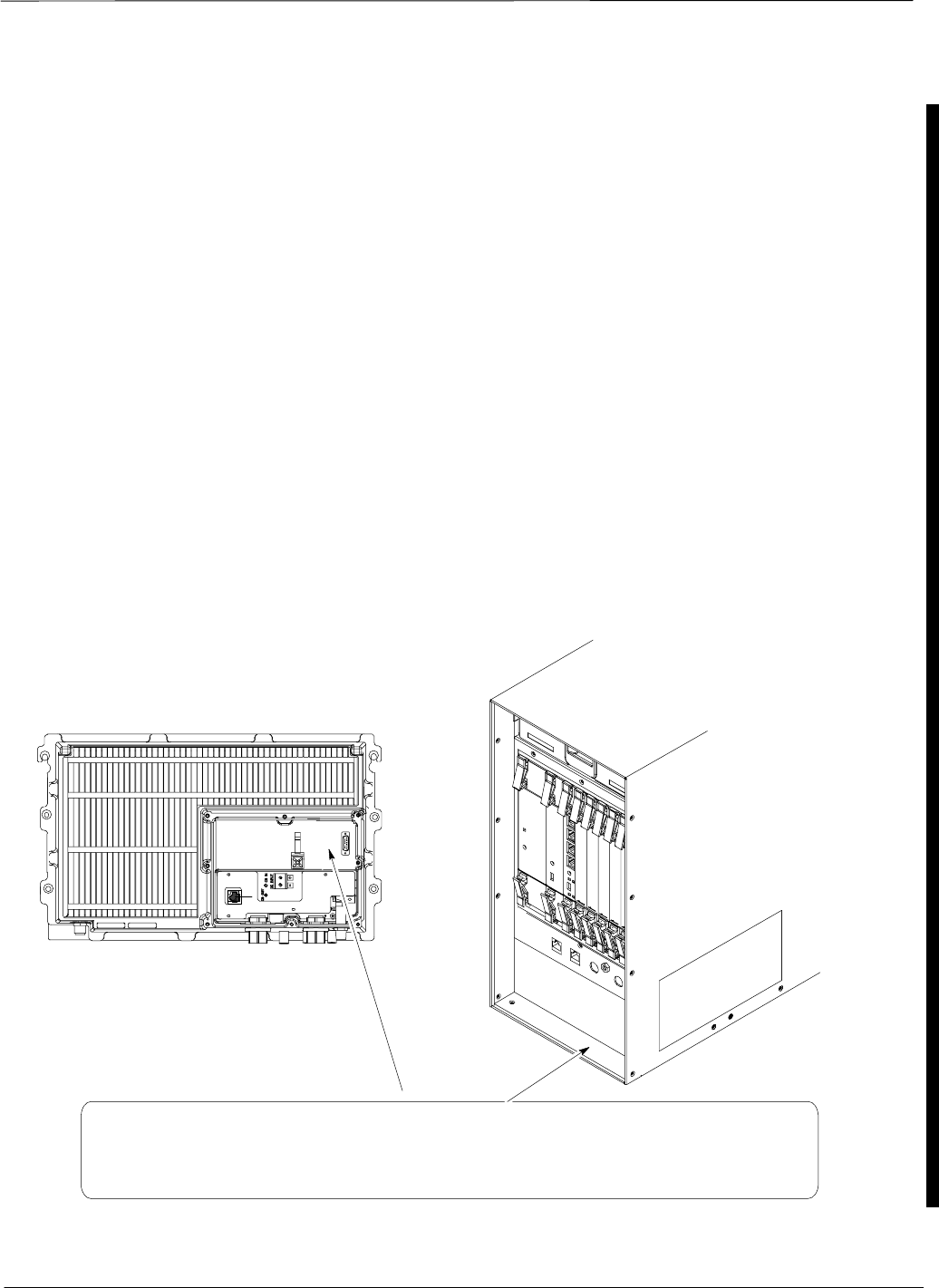
FCC Requriements – continued
Jun 2004 1X SC480 BTS Hardware Installation, Optimization/ATP, and FRU xxv
DRAFT
If this equipment causes harm to the telephone network, the telephone
company will notify you in advance that temporary discontinuance of
service may be required. If advance notice is not practical, the telephone
company will notify you as soon as possible. Also, you will be advised
of your right to file a complaint with the FCC if you believe it is
necessary.
If you experience trouble operating this equipment with the T1, please
contact:
Global Customer Network Resolution Center (CNRC)
1501 W. Shure Drive, 3436N
Arlington Heights, Illinois 60004
Phone Number: (847) 632–5390
for repair and/or warranty information. You should not attempt to repair
this equipment yourself. This equipment contains no customer or
user–serviceable parts.
Changes or modifications not expressly approved by Motorola could
void your authority to operate this equipment.
FCC Label and Location
Model No. ___________
Model No. Motorola
MOTOROLA
FCC ID IHET5EJ1
SERIAL NO.
FCC ID: IHET6EK1
Complies with Part 68, FCC Rules
FCC Reg. No.
US: IHEDENANSC4801XDO
Label placed
here
LABEL SHOWN ISFOR
DISPLAY PURPOSES
ONLY. BTS
CCLPA

General Safety
xxvi 1X SC480 BTS Hardware Installation, Optimization/ATP, and FRU Jun 2004
DRAFT
Remember! . . . Safety
depends on you!!
The following general safety precautions must be observed during all
phases of operation, service, and repair of the equipment described in
this manual. Failure to comply with these precautions or with specific
warnings elsewhere in this manual violates safety standards of design,
manufacture, and intended use of the equipment. Motorola, Inc. assumes
no liability for the customer’s failure to comply with these requirements.
The safety precautions listed below represent warnings of certain dangers
of which we are aware. You, as the user of this product, should follow
these warnings and all other safety precautions necessary for the safe
operation of the equipment in your operating environment.
Ground the instrument
To minimize shock hazard, the equipment chassis and enclosure must be
connected to an electrical ground. If the equipment is supplied with a
three-conductor ac power cable, the power cable must be either plugged
into an approved three-contact electrical outlet or used with a
three-contact to two-contact adapter. The three-contact to two-contact
adapter must have the grounding wire (green) firmly connected to an
electrical ground (safety ground) at the power outlet. The power jack and
mating plug of the power cable must meet International Electrotechnical
Commission (IEC) safety standards.
Refer to Grounding Guideline for Cellular Radio
Installations – 68P81150E62.
NOTE
Do not operate in an explosive
atmosphere
Do not operate the equipment in the presence of flammable gases or
fumes. Operation of any electrical equipment in such an environment
constitutes a definite safety hazard.
Keep away from live circuits
Operating personnel must:
Snot remove equipment covers. Only Factory Authorized Service
Personnel or other qualified maintenance personnel may remove
equipment covers for internal subassembly, or component
replacement, or any internal adjustment.
Snot replace components with power cable connected. Under certain
conditions, dangerous voltages may exist even with the power cable
removed.
Salways disconnect power and discharge circuits before touching them.
General Safety – continued
Jun 2004 1X SC480 BTS Hardware Installation, Optimization/ATP, and FRU xxvii
DRAFT
Do not service or adjust alone
Do not attempt internal service or adjustment, unless another person,
capable of rendering first aid and resuscitation, is present.
Do not substitute parts or
modify equipment
Because of the danger of introducing additional hazards, do not install
substitute parts or perform any unauthorized modification of equipment.
Contact Motorola Warranty and Repair for service and repair to ensure
that safety features are maintained.
Dangerous procedure
warnings
Warnings, such as the example below, precede potentially dangerous
procedures throughout this manual. Instructions contained in the
warnings must be followed. You should also employ all other safety
precautions that you deem necessary for the operation of the equipment
in your operating environment.
Dangerous voltages, capable of causing death, are present in this
equipment. Use extreme caution when handling, testing, and
adjusting.
WARNING

Revision History
xxviii 1X SC480 BTS Hardware Installation, Optimization/ATP, and FRU Jun 2004
DRAFT
Manual Number
68P09262A08–1
Manual Title
1X SC480 BTS Hardware Installation, Optimization/ATP, and FRU
Software Release 2.16.5.X
Version Information
The following table lists the manual version, date of version, and
remarks on the version.
Version
Level Date of Issue Remarks
–1 Jun 18, 2004 DRAFT – For General engineering review

Jun 2004 1X SC480 BTS Hardware Installation, Optimization/ATP, and FRU
DRAFT
Chapter 1: Introduction
Table of Contents
Introduction 1-1 . . . . . . . . . . . . . . . . . . . . . . . . . . . . . . . . . . . . . . . . . . . . . . . . . . . . .
Scope of this Document 1-1 . . . . . . . . . . . . . . . . . . . . . . . . . . . . . . . . . . . . .
Manual Order 1-1 . . . . . . . . . . . . . . . . . . . . . . . . . . . . . . . . . . . . . . . . . . . . .
Site Cleanliness 1-3 . . . . . . . . . . . . . . . . . . . . . . . . . . . . . . . . . . . . . . . . . . .
Site Manager 1-3 . . . . . . . . . . . . . . . . . . . . . . . . . . . . . . . . . . . . . . . . . . . . .
System Diagrams 1-3 . . . . . . . . . . . . . . . . . . . . . . . . . . . . . . . . . . . . . . . . . .
Configurations 1-3 . . . . . . . . . . . . . . . . . . . . . . . . . . . . . . . . . . . . . . . . . . . .
Required Documents 1-5 . . . . . . . . . . . . . . . . . . . . . . . . . . . . . . . . . . . . . . . . . . . . . .
Installation 1-5 . . . . . . . . . . . . . . . . . . . . . . . . . . . . . . . . . . . . . . . . . . . . . . .
Abbreviations and acronyms 1-5 . . . . . . . . . . . . . . . . . . . . . . . . . . . . . . . . .
CDMA 1.9 GHz Operating Frequency Programming Information 1-8 . . . . . . . . . .
Introduction 1-8 . . . . . . . . . . . . . . . . . . . . . . . . . . . . . . . . . . . . . . . . . . . . . .
1900 MHz PCS Channels 1-8 . . . . . . . . . . . . . . . . . . . . . . . . . . . . . . . . . . .
Calculating 1900 MHz Center Frequencies 1-9 . . . . . . . . . . . . . . . . . . . . . .
Installation Tools and Materials 1-11 . . . . . . . . . . . . . . . . . . . . . . . . . . . . . . . . . . . . .
Introduction 1-11 . . . . . . . . . . . . . . . . . . . . . . . . . . . . . . . . . . . . . . . . . . . . . .
Tools and Materials for Installation 1-11 . . . . . . . . . . . . . . . . . . . . . . . . . . . .
ATP Tools and Materials 1-14 . . . . . . . . . . . . . . . . . . . . . . . . . . . . . . . . . . . . . . . . . .
Policy 1-14 . . . . . . . . . . . . . . . . . . . . . . . . . . . . . . . . . . . . . . . . . . . . . . . . . . .
Test equipment calibration 1-14 . . . . . . . . . . . . . . . . . . . . . . . . . . . . . . . . . . .
Test cable calibration 1-14 . . . . . . . . . . . . . . . . . . . . . . . . . . . . . . . . . . . . . . .
Equipment Warm–up 1-14 . . . . . . . . . . . . . . . . . . . . . . . . . . . . . . . . . . . . . . .
Test Equipment List 1-15 . . . . . . . . . . . . . . . . . . . . . . . . . . . . . . . . . . . . . . . .
Optional Equipment 1-19 . . . . . . . . . . . . . . . . . . . . . . . . . . . . . . . . . . . . . . . .
BTS Equipment Identification 1-20 . . . . . . . . . . . . . . . . . . . . . . . . . . . . . . . . . . . . . .
Overview 1-20 . . . . . . . . . . . . . . . . . . . . . . . . . . . . . . . . . . . . . . . . . . . . . . . .
Shelf Device ID Numbers for Stand–Alone 1-24 . . . . . . . . . . . . . . . . . . . . .
HSO and MSO 1-26 . . . . . . . . . . . . . . . . . . . . . . . . . . . . . . . . . . . . . . . . . . . .
Modem 1-26 . . . . . . . . . . . . . . . . . . . . . . . . . . . . . . . . . . . . . . . . . . . . . . . . . .
BTS Rear Panel 1-26 . . . . . . . . . . . . . . . . . . . . . . . . . . . . . . . . . . . . . . . . . . .
Outdoor Enclosure Equipment Identification 1-29 . . . . . . . . . . . . . . . . . . . . . . . . . . .
Outdoor Enclosure Equipment Identification 1-29 . . . . . . . . . . . . . . . . . . . .
Thermal Management Enclosure 1-29 . . . . . . . . . . . . . . . . . . . . . . . . . . . . . .
Power Distribution Enclosure 1-30 . . . . . . . . . . . . . . . . . . . . . . . . . . . . . . . .
Combined Compact Linear Power Amplifier 1-31 . . . . . . . . . . . . . . . . . . . .
Installation and ATP Order 1-32 . . . . . . . . . . . . . . . . . . . . . . . . . . . . . . . . . . . . . . . . .
1

Table of Contents – continued
1X SC480 BTS Hardware Installation, Optimization/ATP, and FRU Jun 2004
DRAFT
Indoor Installation Order 1-32 . . . . . . . . . . . . . . . . . . . . . . . . . . . . . . . . . . . .
Outdoor Installation Order 1-32 . . . . . . . . . . . . . . . . . . . . . . . . . . . . . . . . . . .
ATP Order 1-32 . . . . . . . . . . . . . . . . . . . . . . . . . . . . . . . . . . . . . . . . . . . . . . .
1

Introduction
Jun 2004 1-1
1X SC480 BTS Hardware Installation, Optimization/ATP, and FRU
DRAFT
Scope of this Document
This document provides information pertaining to the hardware
installation, cabling installation, ATP and Field Replaceable Unit (FRU)
procedures of the Motorola SCt480 CDMA Base Transceiver
Subsystem (BTS), 1.9 GHz, +27 VDC versions. Information on Circuit
and Packet Backhaul, Expansion, and Logical BTS are also included.
The FRU procedures cover all components that are considered
replaceable.
An individual SCt480 BTS will be referred to as the “BTS” for the
remainder of this document.
For detailed installation information of non-Motorola equipment, refer to
the vendor manuals provided with such equipment.
Manual Order
The installation order is the order of the manual starting at Chapter 1 and
continuing through Chapter 5. After hardware installation has been
completed, run the ATP for the system by following the procedures
defined in Chapter 6 of this manual.
Chapter 1
“Introduction” — This is a brief outline of the manual. Also provided is
a list of additional documents and tools necessary to complete the
procedures.
Chapter 2
“Site Preparation” — This chapter contains the necessary information to
verify the condition of the site.
Chapter 3
“BTS Cables” — This chapter contains the general information on the
cables required for the Compact BTS.
Chapter 4
“Installation of Equipment, Cables, and GPS” — This chapter contains
procedures for installing the equipment, external AC, DC, data, ground
antenna, and GPS cabling.
Chapter 5
“Pre–Power–Up, Initial Power, and Removal of Power” — This chapter
contains procedures for performing electrical power checks.
Chapter 6
“Optimization and Calibration Procedures” – This chapter contains
general information and procedures for optimizing the BTS.
1

Introduction – continued
DRAFT
1X SC480 BTS Hardware Installation, Optimization/ATP, and FRU Jun 2004
1-2
Chapter 7
“Acceptance Test Procedures” – This chapter contains general
information and procedures for testing the BTS.
Chapter 8
“Leaving the Site” – This chapter contains general information and
procedures for preparing to leave and departing the site.
Chapter 9
“Field Replaceable Units” – This chapter contains general information
and procedures for removing and installing boards, cards and modules of
the BTS.
Chapter 10
“Reference Procedures Performed at OMC–R ” – This chapter contains
general information and procedures to be followed by the OMC–R
operator.
Appendix A
“MCC–Data Only ” – This appendix contains general information and
test procedures for the DO card.
Appendix B
“Test Equipment Preparation ” – This appendix contains general
information and procedures for setting up the test equipment.
Appendix C
“Download ROM Code ” – This appendix contains general information
and procedures for the loading ROM code into the BTS cards.
Appendix D
“MMI Cable ” – This appendix contains general information and
procedures for making an MMI cable.
Appendix E
“Expansion BTS Configuration” – This appendix contains general
information and interconnect diagrams for expansion configuration.
Appendix F
“Logical BTS LAN Configuration for Compact BTS (Indoor) ” – This
appendix contains general information and interconnect diagrams for
logical BTS.
Appendix G
“Integrated BTS Router Preliminary Operations” – This appendix
contains general information and procedures IBR and span line
verification.
1

Introduction – continued
Jun 2004 1-3
1X SC480 BTS Hardware Installation, Optimization/ATP, and FRU
DRAFT
Appendix H
“Integrated BTS Router Installation ” – This appendix contains general
information and procedures IBR and span line installation.
Appendix I
“Packet Backhaul BTS ” – This appendix contains general information
and procedures for packet backhaul operation with LMF Help.
Appendix J
“BTS Highway Cell Configuration” – This appendix contains general
information and procedures for highway configuration operation.
Site Cleanliness
While performing the procedures provided in this document, ensure
that:
Sfor an internal installation, the site is kept clean and free of tracked-in
dirt
Sall packing material has been removed from the equipment.
Sall tools not currently in use are picked-up as the installation
progresses.
Sall trash is removed from the site at the end of each day and after the
installation is complete.
Sequipment is covered with a tarpaulin whenever possible.
Suse a shop-vac whenever you perform an internal installation
procedure that generates dust, such as drilling or cutting.
Site Manager
The site manager is the person in charge of and responsible for the full
site. The installer will be verifying a variety of conditions with the site
manager.
System Diagrams
Figure 1-1 shows the BTS mounted on a rack. The configuration is for
indoor operation.
Configurations
The BTS supports the omni configuration.
The power configuration for the BTS is:
SDC power only
The synchronization configurations for the BTS are:
SRemote GPS Receiver – synchronous operation
SRF GPS
1
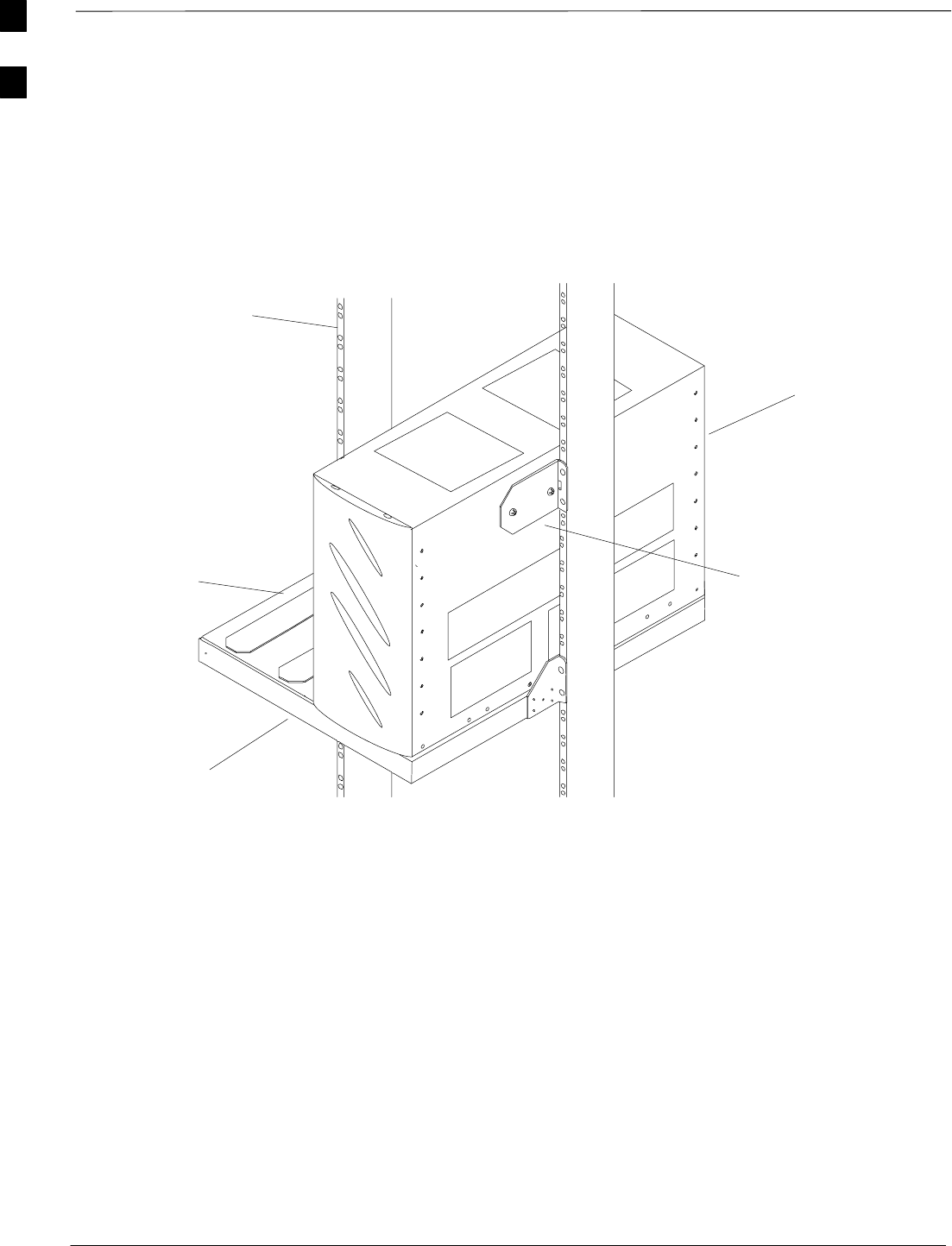
Introduction – continued
DRAFT
1X SC480 BTS Hardware Installation, Optimization/ATP, and FRU Jun 2004
1-4
ti–cdma–wp–00303–v01–ildoc–ah
BTS
Rack
Mounting Plate
Mounting
Bracket
Location for
Second BTS
NOTE:
SIngle BTS setup shown.
Compact PA and RGPS Head
are not shown
Figure 1-1: Mounted BTS and Rack
1

Required Documents
Jun 2004 1-5
1X SC480 BTS Hardware Installation, Optimization/ATP, and FRU
DRAFT
Installation
The following documents are required to perform the installation, ATP
and FRU procedures of the cell site equipment:
SSCt480 BTS Hardware Installation, Optimization/ATP and FRU –
68P09262A08 (This manual)
SStandards and Guidelines for Communication Sites
– Hard copy (Motorola Part Number 6881089E50–A)
– CD–ROM (Motorola Part Number 9882904Y01)
SGrounding Guidelines for Cellular Radio Installations
(Motorola part number 68P81150E62) or
– Appendix C of Standards and Guidelines for Communication Sites
SSite Document (generated by Motorola Systems Engineering), which
includes:
– site specific documentation
– channel allocation
– contact list (customer)
– ancillary/expendable equipment list
– site wiring lists
– contact list (Motorola support)
– job box inventory
SDemarcation Document (Scope of Work agreement)
SInstallation manuals for non-Motorola equipment (for reference
purposes).
Abbreviations and acronyms
Table 1–1 contains a list of the abbreviations and acronyms used in this
manual.
Table 1-1: Abbreviations and Acronyms
Acronym Description
ACT Active
ALM Alarm
ATP Acceptance Test Procedure
AUX Auxiliary
BLO Bay Level Offset
BSS Base Station System
BTS Base Transceiver Station or Subsystem
BBX Broad Band Transceiver
table continued on next page
1

Required Documents – continued
DRAFT
1X SC480 BTS Hardware Installation, Optimization/ATP, and FRU Jun 2004
1-6
Table 1-1: Abbreviations and Acronyms
Acronym Description
CAL Calibration
CBIO Compact BTS Input/Output
CBSC Centralized Base Station Controller
cCLPA Compact Combined Linear Power Amplifier
CCP2 CDMA Channel Processor 2
CDF Configuration Data File
CDMA Code Division Multiple Access
cMPC Compact Multi–coupler Preselector Card
CRMS Cellular Remote Monitoring System
CSA Clock Synchronization Alarms
DLM Download Manager
EMPC Expansion Compact Mulit–Preselector Card
ERP Effective Rated Power
ESD Electrostatic Discharge
EXP Expansion
FREQ Frequency
FRU Field Replaceable Unit
FTP File Transfer Protocol
GLI 3 Group Line Interface III
GPS Global Positioning System or Satellite
HMS Heat Management System
HSO High Stability Oscillator
HX Heat Exchanger
INS In–Service
INS_ACT In–Service Active
INS_SBY In–Service Standby
LAN Local Area Network
LIF Load Information File
LMF Local Maintenance Facility
table continued on next page
1

Required Documents – continued
Jun 2004 1-7
1X SC480 BTS Hardware Installation, Optimization/ATP, and FRU
DRAFT
Table 1-1: Abbreviations and Acronyms
Acronym Description
LMT Local Maintenance Tool
MCC Multi–Channel CDMA
MCC–DO Multi–Channel CDMA Data Only
MMI Man–Machine Interface
MON Monitor
MSO Medium Stability Oscillator
NECB Network Element Configuration Base
NECF Network Element Configuration File
NECJ Network Element Change Journal
OMC–R Operations and Maintenance Center – Radio
OOS Out–of–Service
PDE Power Distribution Enclosure
PSM Power Supply Module
PWR Power
RAM Random Access Memory
ROM Read Only Memory
RF GPS Radio Frequency Global Positioning System
RGPS Remote Global Positioning System
RX Receive
SDCX Synchronization Daisy–Chaining and
eXpansion
STA Status
SYNC Synchronization
TME Thermal Management Enclosure
TX Transmit
1

CDMA 1.9 GHz Operating Frequency Programming Information
1-8 1X SC480 BTS Hardware Installation, Optimization/ATP, and FRU Jun 2004
DRAFT
Introduction
Programming of each of the BTS BBX synthesizers is performed by the
BTS GLI cards over the Concentration Highway Interface (CHI) bus.
This programming data determines the transmit and receive operating
frequencies (channels) for each BBX.
1900 MHz PCS Channels
Figure 1-2 shows the valid channels for the North American PCS
1900 MHz frequency spectrum. There are 10 CDMA wireline or
non–wireline band channels used in a CDMA system (unique per
customer operating system).
FREQ (MHz)
RX TX
275
1175
CHANNEL
1863.75
925
1851.2525
1871.25425
675 1883.75
1896.25
1908.75
1943.75
1931.25
1951.25
1963.75
1976.25
1988.75
A
D
B
E
F
C
FW00463
Figure 1-2: North America PCS Frequency Spectrum (CDMA Allocation)
1

CDMA 1.9 GHz Operating Frequency Programming Information – continued
Jun 2004 1X SC480 BTS Hardware Installation, Optimization/ATP, and FRU 1-9
DRAFT
Calculating 1900 MHz Center
Frequencies
Table 1-2 shows selected 1900 MHz CDMA candidate operating
channels, listed in both decimal and hexadecimal, and the corresponding
transmit, and receive frequencies. Center frequencies (in MHz) for
channels not shown in the table may be calculated as follows:
STX = 1930 + 0.05 * Channel#
Example: Channel 262
TX = 1930 + 0.05 * 262 = 1943.10 MHz
SRX = TX – 80
Example: Channel 262
RX = 1943.10 – 50 = 1863.10 MHz
Actual frequencies used depend on customer CDMA system frequency
plan.
Each CDMA channel requires a 1.77 MHz frequency segment. The
actual CDMA carrier is 1.23 MHz wide, with a 0.27 MHz guard band on
both sides of the carrier.
Minimum frequency separation required between any CDMA carrier and
the nearest NAMPS/AMPS carrier is 900 kHz (center-to-center).
Table 1-2: 1900 MHz TX and RX Frequency vs. Channel
Channel Number
Decimal Hex Transmit Frequency (MHz)
Center Frequency Receive Frequency (MHz)
Center Frequency
25 0019 1931.25 1851.25
50 0032 1932.50 1852.50
75 004B 1933.75 1853.75
100 0064 1935.00 1855.00
125 007D 1936.25 1856.25
150 0096 1937.50 1857.50
175 00AF 1938.75 1858.75
200 00C8 1940.00 1860.00
225 00E1 1941.25 1861.25
250 00FA 1942.50 1862.50
275 0113 1943.75 1863.75
300 012C 1945.00 1865.00
325 0145 1946.25 1866.25
350 015E 1947.50 1867.50
375 0177 1948.75 1868.75
400 0190 1950.00 1870.00
425 01A9 1951.25 1871.25
450 01C2 1952.50 1872.50
475 01DB 1953.75 1873.75
500 01F4 1955.00 1875.00
525 020D 1956.25 1876.25
550 0226 1957.50 1877.50
table continued next page
1

CDMA 1.9 GHz Operating Frequency Programming Information – continued
1-10 1X SC480 BTS Hardware Installation, Optimization/ATP, and FRU Jun 2004
DRAFT
Table 1-2: 1900 MHz TX and RX Frequency vs. Channel
Channel Number
Decimal Hex Receive Frequency (MHz)
Center Frequency
Transmit Frequency (MHz)
Center Frequency
575 023F 1958.75 1878.75
600 0258 1960.00 1880.00
625 0271 1961.25 1881.25
650 028A 1962.50 1882.50
675 02A3 1963.75 1883.75
700 02BC 1965.00 1885.00
725 02D5 1966.25 1886.25
750 02EE 1967.50 1887.50
775 0307 1968.75 1888.75
800 0320 1970.00 1890.00
825 0339 1971.25 1891.25
850 0352 1972.50 1892.50
875 036B 1973.75 1893.75
900 0384 1975.00 1895.00
925 039D 1976.25 1896.25
950 03B6 1977.50 1897.50
975 03CF 1978.75 1898.75
1000 03E8 1980.00 1900.00
1025 0401 1981.25 1901.25
1050 041A 1982.50 1902.50
1075 0433 1983.75 1903.75
1100 044C 1985.00 1905.00
1125 0465 1986.25 1906.25
1150 047E 1987.50 1807.50
1175 0497 1988.75 1908.75
1

Installation Tools and Materials
Jun 2004 1-11
1X SC480 BTS Hardware Installation, Optimization/ATP, and FRU
DRAFT
Introduction
Many of the tools and materials depend on the style of the wall, pole, or
rack on which the mounting bracket is being installed. The tools and
materials required to install the BTS hardware are specified for each
mounting style. Due to the variability of mounting styles, additional
tools and materials may be required to meet specific site needs.
Tools and Materials for
Installation
The tools and materials listed in Table 1-3 are recommended to properly
and safely perform the installation procedures.
Table 1-3: Recommended Tools and Materials for Rack Mounting
Hand Tools Materials Purpose
Adjustable Torque ratchet and socket
set Customer Supplied General torquing of screws and nuts.
T10, T20, T30, Security T20,
Security T30 Torx, cross–recess,
flathead bits, 1/4–in. hex
Customer Supplied General purpose use
Torque driver wrench, 1/4–in. hex
female drive, 0–10 N–M (Utica P/N TCI–150 R/A
3/8–in. or equivalent)
Customer Supplied
General torquing of screws and nuts.
Power Drill, 1/4–in or 3/8–in drive Appropriate wood and
masonry drill bits (Standard
set may be adequate)
Customer Supplied
Drill holes in wood and light concrete
Hammer Drill Appropriate masonry drill
bits (Customer Supplied) Rack installation to floor and RGPS
to wall
Adjustable Wrench Customer Supplied General purpose use
Mechanical lifting device Customer Supplied For lifting equipment
Bucklestrap Cutting Tool (Motorola P/N
6604809N01) Pole Mounting
Tape Measure Customer Supplied General purpose measurement
Heavy Gloves Customer Supplied Hand Safety
Safety Glasses Customer Supplied Eye Safety
Tin Snips Customer Supplied General purpose metal cutting
Hacksaw Various blades
(Customer Supplied) Cutting large coax cable
Metal File Fine cut
(Customer Supplied) Coax cable preparation
Flashlight Customer Supplied General purpose use
Utility Knife Customer Supplied General purpose cutting
Small Flathead Screwdriver Customer Supplied General purpose use
1

Installation Tools and Materials – continued
DRAFT
1X SC480 BTS Hardware Installation, Optimization/ATP, and FRU Jun 2004
1-12
Table 1-3: Recommended Tools and Materials for Rack Mounting
Hand Tools PurposeMaterials
Small Phillips Screwdriver Customer Supplied General purpose use
Hex Crimping Tool Various die sets
(Customer Supplied) Create RF cabling and power/ground
cabling
RJ45 Crimping Tool (Tyco P/N 2–231652–1,
853400–0, 853400–1,
853400–7 or equivalent)
Customer Supplied
Create RJ11/RJ45 cabling
5/16 Breakaway Torque Wrench,
9–in. lb Customer Supplied SMA Connectors
13/16 Breakaway Torque Wrench
38–in. lb Customer Supplied N Connectors
Volt/Ohmmeter or Digital Multimeter Customer Supplied Voltage and continuity testing
Label Maker Customer Supplied General purpose marking
cCLPA Installation Handles Motorola P/N:
5587763T01 For installing the cCLPA
Wire Strippers Customer Supplied Accommodates 6 AWG to 26 AWG
RTV Sealant
(Customer Supplied) Weatherproofing openings for cable
pass through
electrical tape
(Customer Supplied) General purpose use
Fine Grit Sandpaper
(Customer Supplied) Finishing coax cable surfaces
Cable Tie–wraps various
sizes.
(Customer Supplied)
General purpose dressing of cables
15–pin D–sub plug and
termination equipment
(Customer Supplied)
For RGPS cabling
BNC male style connectors
(Customer Supplied) Coaxial span cable, interframe
cabling
N–male and N–female style
connectors for 1/2–in Heliax
(Customer Supplied)
Cabling between BTS, PA, and
Antenna
7/16 DIN connector for
1/2–in and 7/8–in Heliax
(Customer Supplied)
Antenna cabling
RF Cabling, 1/2–in and
7/8–in Heliax Cabling between BTS, PA, and
Antenna
Braided Coax
(Customer Supplied) Coaxial span cable, interframe
cabling
10AWG two–wire stranded
(Customer Supplied) Power cabling
1

Installation Tools and Materials – continued
Jun 2004 1-13
1X SC480 BTS Hardware Installation, Optimization/ATP, and FRU
DRAFT
Table 1-3: Recommended Tools and Materials for Rack Mounting
Hand Tools PurposeMaterials
6 AWG stranded
(Customer Supplied) Ground cabling
Assorted ground lugs
(6AWG, 10 AWG) ring style
(Customer Supplied)
Site ground cabling, Core power
input
Assortment of flat washers,
lock washers
(Customer Supplied)
Mounting equipment to racks and for
general purpose
Assortment of nuts M3 – M6
(Customer Supplied) Mounting equipment to racks and for
general purpose
Rack screws (depends on
rack style used)
(Customer Supplied)
Rack mounting
T1/E1 span cabling (4 or 8
wire TP style)
(Customer Supplied)
Span and cCLPA signal cabling
ILSCO p/n CRB–6L2–14–58
two–hole ground lugs or
equiv. Hole spacing 5/8”,
hole sizes for 1/4” bolt, tang
width 13/32”.
(Customer Supplied)
Ground Lugs
Chalk or marker to mark
location on rack
(Customer Supplied)
1

ATP Tools and Materials
DRAFT
1X SC480 BTS Hardware Installation, Optimization/ATP, and FRU Jun 2004
1-14
Policy
To ensure consistent, reliable, and repeatable test results, test equipment
meeting the following technical criteria should be used to perform the
ATP on the BTS equipment.
During manual testing, you can substitute supported test
equipment with other test equipment models not supported
by the LMF. However, they must meet the same technical
specifications.
NOTE
It is the responsibility of the customer to account for any measurement
variances and /or additional losses / inaccuracies that can be introduced
as a result of these substitutions. Before beginning the ATP, make sure
that the test equipment needed is on hand and operating properly.
Test equipment calibration
Optimal system performance and capacity depend on regular test
equipment service, calibration, and characterization. Follow the original
equipment manufacture (OEM) recommended maintenance and
calibration schedules closely.
Test cable calibration
Equipment test cables are very important in the ATP. It is recommended
that the cable calibration be run at every BTS with the test cables
attached. This method compensates for test cable insertion loss within
the test equipment itself. No other allowance for test cable insertion loss
needs to be made during the performance of tests.
Another method is to account for the loss by entering it into the Local
Maintenance Facility (LMF) during the optimization procedure. This
method requires accurate test cable characterization in a lab
environment. The cable should be tagged with the characterization
information prior to field optimization.
Equipment Warm–up
After arriving at the a site, the test equipment should be plugged in and
turned on to allow warm up and stabilization to occur for as long as
possible. The following pieces of test equipment must be warmed–up for
a minimum of 60 minutes prior to the ATP.
SCommunications Test Set
SPower Meter
1

ATP Tools and Materials – continued
Jun 2004 1-15
1X SC480 BTS Hardware Installation, Optimization/ATP, and FRU
DRAFT
Test Equipment List
The following pieces of test equipment are required during the ATP.
Common assorted tools like screwdrivers and keys are not listed, but are
still required. Read the owners manual on all of the following major
pieces of test equipment to understand their individual operation prior to
use in optimization.
Always refer to specific OEM test equipment
documentation for detailed operating instructions.
NOTE
CDMA LMF Hardware Requirements
A CDMA LMF computer platform that meets the following
requirements (or better) is recommended:
SNotebook computer
SPCMCIA to Serial I/O Adapter
S266 MHz (32 bit CPU) Pentium processor
S4 GigaByte internal hard disk drive
SSVGA 12.1 inch active matrix color display with 1024 x 768
(recommended) or 800 x 600 pixel resolution and capability to display
more than 256 colors
S128 MB RAM minimum (98SE) or 256 (Windows 2000)
S20X CD ROM drive
S3–1/2 inch floppy drive
SSerial port (COM 1)
SSerial Port (COM 2)
SParallel port (LPT 1)
SPCMCIA Ethernet interface card (for example, 3COM Etherlink III)
with a 10Base–T–to–coax adapter
SWindows 98 SE or higher operating system
If 800 x 600 pixel resolution is used, the CDMA LMF
window must be maximized after it is displayed.
NOTE
Ethernet LAN Transceiver (part of all LMF kits)
SPCMCIA Ethernet Adapter + Ethernet UTP Adapter 3COM Model –
Etherlink III 3C589B
used with
STransition Engineering Model E–CX–TBT–03 10BaseT/10Base 2
Converter
1

ATP Tools and Materials – continued
DRAFT
1X SC480 BTS Hardware Installation, Optimization/ATP, and FRU Jun 2004
1-16
CDMA LMF Software
The Local maintenance Facility (LMF) application program is a
graphical user interface (GUI)–based software tool. This product is
specifically designed to provide cellular communication field personnel
with the capability to support the following CDMA Base Transceiver
Station (BTS) operations:
SInstallation
SMaintenance
SCalibration
SOptimization
RS232 to GPIB Interface
One National Instruments GPIB–232–CT with Motorola
CGDSEDN04X RS232 serial cable or equivalent; used to interface the
LMF to the test equipment.
A Standard RS–232 cable can be used with the following modifications:
SPin 8 (CTS) does not have to be jumpered/shorted to the others as
it is a driver output. The DTR is already a driver output signal.
The other pins are to receivers. Short pins 7, 1, 4, 6 on each cable end:
9–pin D (female) 9–pin D (female)
GND 5 5 GND
RX 3
3 RXTX 2
2 TX
RTS 7 7 RTS
RSD/DCD 1 1 RSD/DCD
DTR 4 4 DTR
DSR 6 6 DSR
Figure 1-3: RS232–IEEE488 Converter Serial Cable Configuration
CTS 8 8 CTS
ON BOTH CONNECTORS SHORT
PINS 7 AND 8;
SHORT PINS 1, 4 AND 6
Communications system analyzer CDMA/analog
IS–95A/B–only test capability – The following communications system
analyzers which provide only IS–95A/B test capability are supported by
the LMF:
SMotorola CyberTest
SHewlett Packard Model HP 8921A/600 Analyzer including 83203B
CDMA Interface, manual control system card, and, for 1900 MHz
BTSs, 83236A/B PCS Interface
1

ATP Tools and Materials – continued
Jun 2004 1-17
1X SC480 BTS Hardware Installation, Optimization/ATP, and FRU
DRAFT
SAdvantest R3465 Analyzer with R3561L signal generator
CDMA2000 1X and IS–95A/B test capability – The following
communications system analyzers which provide both CDMA2000 1X
and IS–95A/B test capability are supported by the LMF:
SAgilent 8935 series E6380A communications test set (formerly HP
8935) with option 200 or R2K for CDMA2000 1X support
SAgilent E4406A
SAdvantest R3267 spectrum analyzer with Advantest R3562 Generator
for IS–95 and cdma200 1X testing
A combination of test equipment supported by the LMF may also be
used during optimization and testing of the RF communications portion
of BTS equipment when the communications system analyzer does not
perform all of the following functions:
SFrequency counter
SDeviation meter
SRF power meter (average and code domain)
SRF signal generator (capable of DSAT/CDMA modulation)
SAudio signal generator
SAC voltmeter (with 600–ohm balanced audio input and high
impedance input mode)
SNoise measurement meter
SC–Message filter
SSpectrum analyzer
SCDMA code domain analyzer
Advantest R3267 with Advantest R3562 Generator are
capable of performing IS–95B and cdma2000 1X tests, if
the required options are installed.
NOTE
GPIB cables
Two Hewlett Packard 10833A or equivalent; 1 or 2 meters long used to
interconnect test equipment and LMF terminal.
Power meter
Gigatronics Model 8541C with 80601A power sensor capable of
measuring from –70 dBm to +23 dBm; supported by the LMF to
perform BTS Total Power measurement.
1

ATP Tools and Materials – continued
DRAFT
1X SC480 BTS Hardware Installation, Optimization/ATP, and FRU Jun 2004
1-18
Model SLN2006A MMI Interface Kit
SMotorola Model TRN9666A null modem board. Connectors on
opposite sides of the board must be used as this performs a null
modem transformation between cables. This board can be used for
10–pin to 8–pin, 25–pin to 25–pin and 10–pin to 10–pin conversions.
SMotorola 30–09786R01 MMI cable or equivalent; used to interface
the LMF serial port connection to GLI, CSA and cCLPA debug serial
ports.
CDMA2000 1X signal generators
SAgilent E4432B signal generator (required for use with Agilent
E4406A when performing Frame Erasure Rate acceptance testing)
or
SAdvantest R3562 signal generator (required for use with Advantest
R3267 when performing Frame Erasure Rate acceptance testing)
Power meter
SHewlett Packard Model HP437B with HP8481A power sensor capable
of measuring from –30 dBm to 20 dBm
or
SGigatronics 8542B power meter
Timing Reference Cables
STwo BNC–male to BNC–male RG316 cables; 3.04 m. (10 ft.) long,
Two BNC–male to BNC–male RG316 cables; 0.61 m. (2 ft.) long
with Two BNC “T” connectors, used to interconnect the
Communications Analyzer to CSA front panel timing references in the
BTS.
RF Attenuators
S30 dB Fixed in–line attenuators, 150 W (Narda 769–30) used in
conjunction with calibration of test cables.
S50 dB attenuator for connection to 30 dB directional coupler
Misc. Components (RF Adaptors, Loads, Cables, etc.)
SAs required to interface test cables and BTS equipment and for
various test set ups. Should include at least (2) 50–Ohm loads (type
N) for calibration, (1) RF short, (2) RF cables, (1) GPIB Box, and (1)
ethernet cable.
RF Load
S150W non–radiating RF load; used (as required) to provide dummy
RF loading during BTS transmit tests.
High–Impedance Conductive Wrist Strap
SMotorola Model 42–80385A59; used to prevent damage from
Electrostatic Discharge (ESD) when handling or working with
modules.
1

ATP Tools and Materials – continued
Jun 2004 1-19
1X SC480 BTS Hardware Installation, Optimization/ATP, and FRU
DRAFT
Directional Coupler
S30 dB attenuation
Optional Equipment
Not all optional equipment specified here will be supported
by the LMF in automated tests or when executing various
measure type commands. It is meant to serve as a list of
additional equipment that might be required during
maintenance and troubleshooting operations.
NOTE
Digital Multimeter
SFluke Model 8062A with Y8134 test lead kit or equivalent; used for
precision dc and ac measurements, requiring 4–1/2 digits.
Frequency Counter
SStanford Research Systems SR620 or equivalent. If direct
measurement of the 3 MHz or 19.6608 MHz references are required.
Spectrum Analyzer
SSpectrum Analyzer (HP8594E with CDMA personality card) or
equivalent; required for manual tests other than standard Receive
band spectral purity and TX cCLPA IM reduction verification tests
performed by the LMF.
LAN Tester
SModel NETcat 800 LAN troubleshooter (or equivalent); Used to
supplement LAN tests using the ohm meter.
Span Line (T1 or E1) Verification Equipment
SAs required for local application
RF Test Cable (if not provided with test equipment)
SMotorola Model TKN8231A; used to connect test equipment to the
BTS transmitter output during optimization procedures.
Oscilloscope
STektronics Model 2445 or equivalent; used for waveform viewing,
timing, and measurements procedures.
CDMA Subscriber Mobile or Portable Radiotelephone
SCDMA compatible with power supply and antenna; used to provide
test transmission and reception during BTS maintenance. Two radios
will be required for system and drive around testing after optimization
and BTS ATP is completed.
1

BTS Equipment Identification
DRAFT
1X SC480 BTS Hardware Installation, Optimization/ATP, and FRU Jun 2004
1-20
Overview
Stand–Alone BTS
The 1X SC480 BTS consists of one shelf of cards and modules within a
metal cabinet. Depending on configuration the BTS may be powered by:
SConverted AC to +27 VDC
SBattery (–48 or +27 VDC)
S+27 VDC
The BTS can support up to two carriers in a non–redundant omni
configuration.
Figure 1-4 shows the two different front vies and Figure 1-5 shows the
rear view of the BTS.
Exapnsion BTS
When more than two carriers are desired, up to 3 additional BTSes may
be added. Up to 8 carriers can be supported in this configuration. The
Starter BTS has the Compact Multi–Preselector Card (cMPC) and the
expansion BTSes contain Expansion Compact Multi–Preselector Cards
(EMPC) in place of the cMPC. In expansion the BTSes are identified as
individual BTSes, (i.e.; BTS–100, BTS–200, BTS–300, BTS–400).
LAN connections are not used. The BTSes will share TX and RX
antennas. Reference Appendix E for interconnect diagrams.
Logical BTS
The BTS software implements the logical BTS capability. Previously, all
BTS frames co–located at a single site had to be identified in the
network with separate and distinct BTS ID numbers. In the Logical BTS
feature, all BTSes located at a single BTS site are identified with unique
Frame ID numbers (Frame ID Numbers 1, 101, 201, 301) under a single
(site) BTS ID number. A logical BTS can consist of up to three BTSes
(up to 8 carriers). When the LMF is connected to the Starter of a logical
BTS, you can access all devices in all of the BTSes that make up the
logical BTS. A logical BTS requires a CDF/NECF file that includes
equipage information for all of the logical BTSes and their devices and a
CBSC file that includes channel data for all of the logical BTSes.
In this configuration LAN connections are used. The Starter BTS has the
Compact Multi–Preselector Card (cMPC) and the expansion BTSes
contain Expansion Compact Multi–Preselector Cards (EMPC) in place
of the cMPC. The BTSes will share TX and RX antennas. Reference
Appendix F for interconnect diagrams.
CCP2 Shelf Card/Module Device ID Numbers Logical
BTS
All cards/modules/boards in the BTSes at a single site, assigned to a
single BTS number, are also identified with unique Device ID numbers
dependent upon the Frame ID number in which they are located. Refer to
Table 1-4 for specific device ID numbers. See Figure 1-6 for shelf
layout.
1

BTS Equipment Identification – continued
Jun 2004 1-21
1X SC480 BTS Hardware Installation, Optimization/ATP, and FRU
DRAFT
Table 1-4: CCP2 Shelf Card/Module Device ID Numbers for Logical BTS
BTS # PSM CSA GLI3 MCC BBX cMPC/E
MPC
1 – 1 1 1 2 3 1 4 –
101 – 101 101 101 102 103 101 104 –
201 – 201 201 201 202 203 201 204 –
301 – 301 301 301 302 303 301 304 –
1
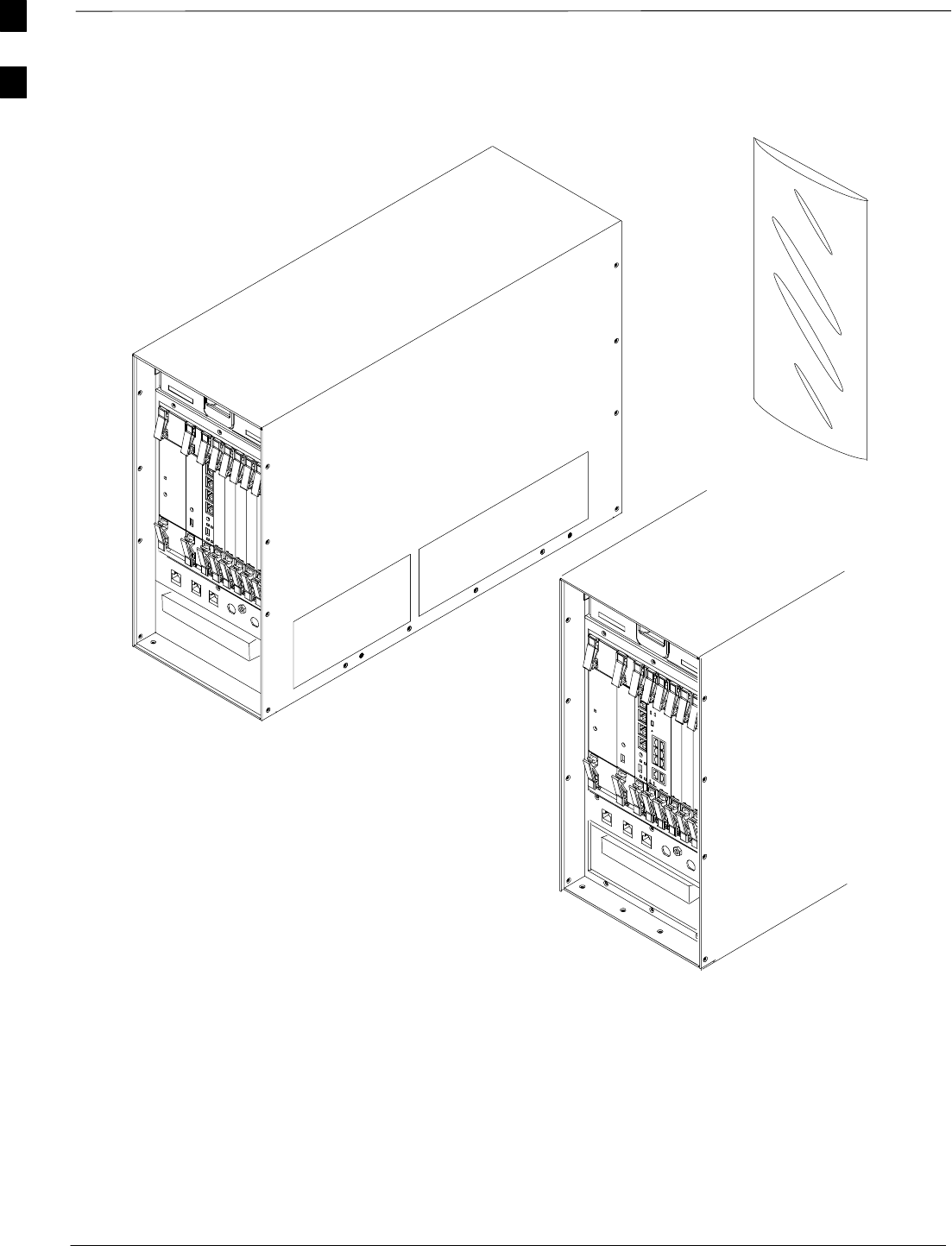
BTS Equipment Identification – continued
DRAFT
1X SC480 BTS Hardware Installation, Optimization/ATP, and FRU Jun 2004
1-22
Figure 1-4: Front View of Compact BTS
CCP2 Shelf with
MCC–DO card
Front Panel cover
removed
Standard CCP2 Shelf
Front Panel cover
removed
Front Panel
Cover
1
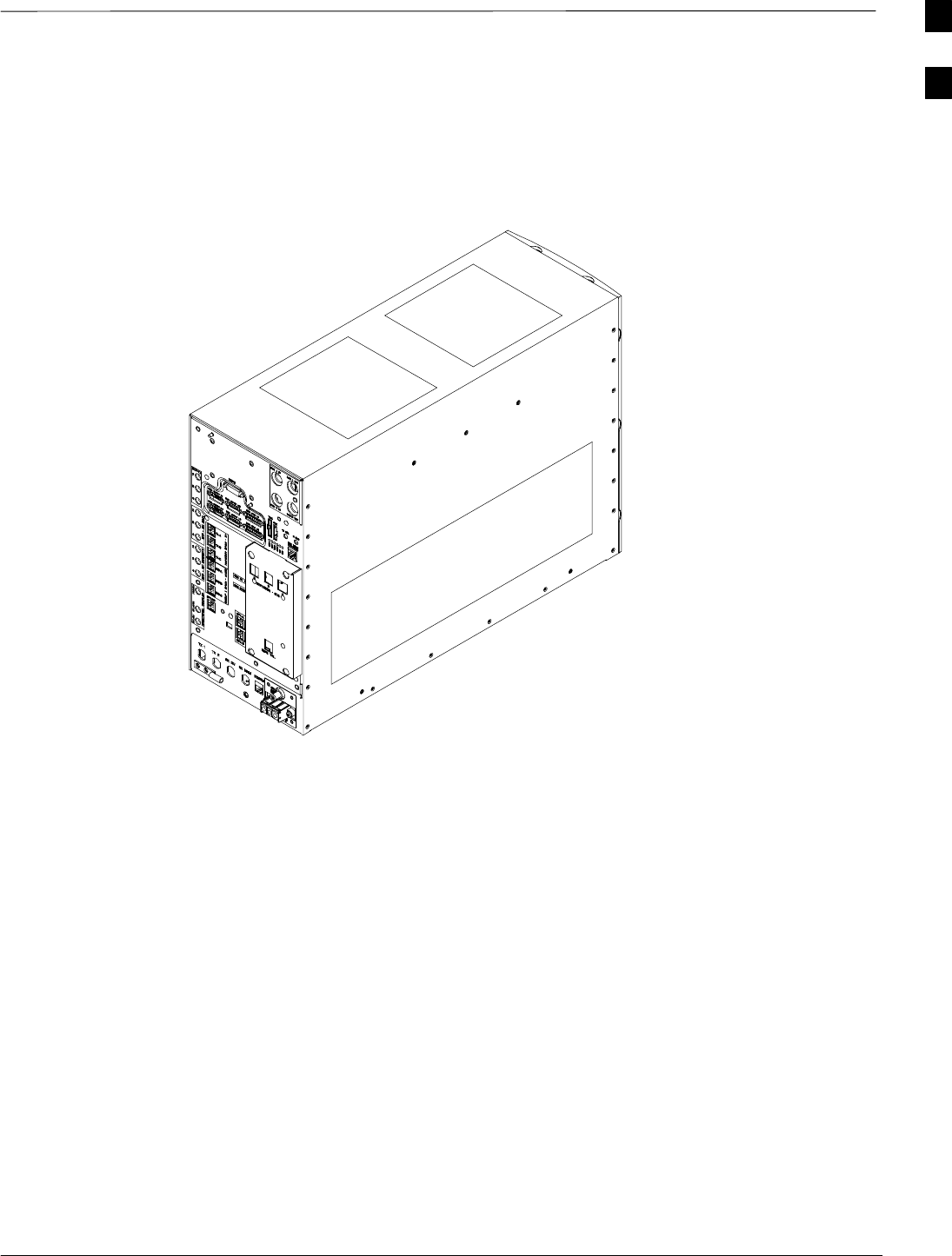
BTS Equipment Identification – continued
Jun 2004 1-23
1X SC480 BTS Hardware Installation, Optimization/ATP, and FRU
DRAFT
RF GPS not shown and
SDCX Module is shown.
Figure 1-5: Rear View of Compact BTS
1
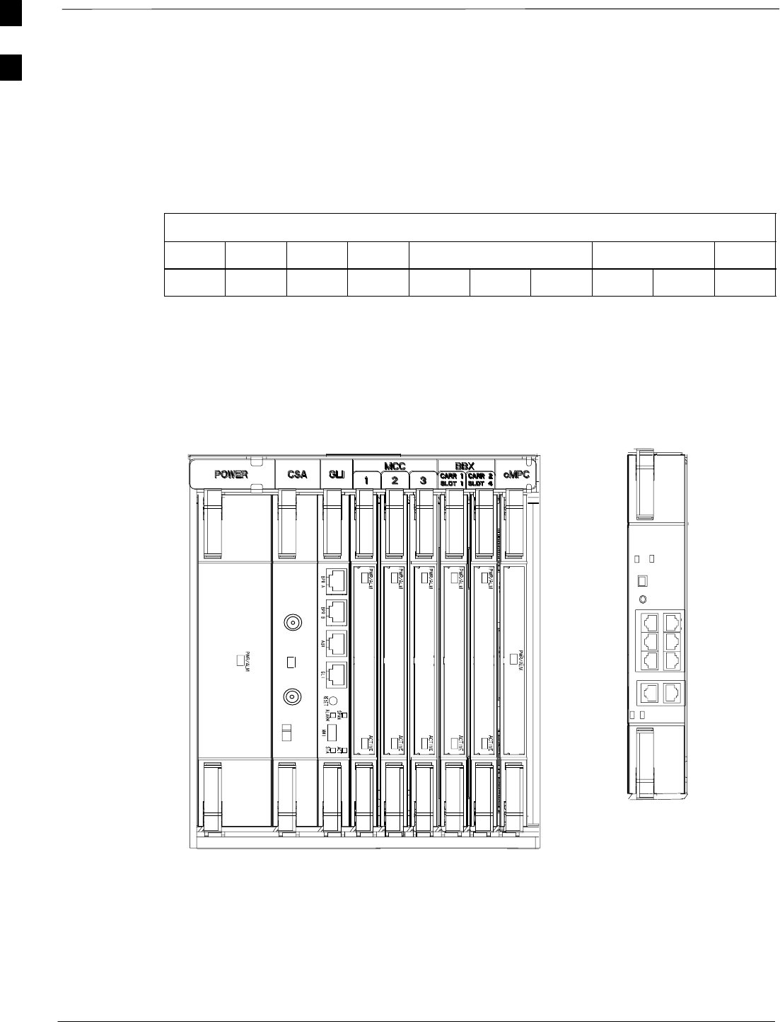
BTS Equipment Identification – continued
DRAFT
1X SC480 BTS Hardware Installation, Optimization/ATP, and FRU Jun 2004
1-24
Shelf Device ID Numbers for
Stand–Alone
All cards/modules/boards in the BTS at a single site assigned to a single
BTS are also identified with unique Device ID numbers. Refer to
Table 1-5 for the Device ID Numbers. Reference Figure 1-6 or
Figure 9-2 for the layout of the shelf.
Table 1-5: Shelf Device ID Numbers
BTS # PS1 CSA GLI MCC BBX cMPC
111112314–
Figure 1-6: CCP2 Shelf Layout
ti–cdma–wp–00310–v01–ildoc–ah
STA/ALM
SYNC MONITOR FREQ. MONITOR
MMI
When used, the MCC–DO
is seated in MCC slots 1
and 2. MCC slot 3 can be
an MCC–1X or a filler
panel.
The following is a list of the cards/modules in CCP 2 Shelf and a brief
description.
1. Power Supply Module
2. CSA
1

BTS Equipment Identification – continued
Jun 2004 1-25
1X SC480 BTS Hardware Installation, Optimization/ATP, and FRU
DRAFT
3. GLI3
4. MCC–1X (or MCC–DO)
5. MCC–1X (or MCC–DO)
6. MCC–1X or Filler Panel
7. BBX–1X (Carrier 1)
8. BBX–1X (Carrier 2)
9. cMPC
Power Supply Module
Occupies the first slot. The same assembly used in the SC48XX series.
Provides power to the cards on the CCP2 shelf.
CSA Card
Occupies the second slot. The Clock Synchronization Alarm card,
combines the functions of the SC4812’s CSM and AMR cards into one.
The CSA timing circuit receives a 1pps signal from the GPS. The CSA
timing circuit generates the CDMA timing signal to the BBX and MCC
cards.
During normal operation the CSA is set up to select the GPS as the first
reference source. With an HSO or MSO as backup, the CSA is set up to
select the HSO or MSO 1 pps as the backup reference source should the
GPS signal fail. .
GLI3 Card
Occupies the third slot. The same card used in the SC48XX series.
Provides interfaces, inter–card communications, operation, and
maintenance functions for all the devices in the CCP2 shelf.
MCC–1X Cards and MCC–DO
Occupies the fourth through sixth slots (MCC slots 1, 2, & 3).
Depending on configuration they will be MCC–1X cards (16s, 32s, 48s,
or 64s). MCC–1X 64s require packet backhaul configuration. This
implements the traffic and control (sync, paging, access) channels of the
BTS.
If the BTS is configured for MCC–Data Only (DO), then MCC slots 1
and 2 will be used with slot 3 containing an MCC–1X card or a filler
panel.
BBX–1X Cards
Occupies the seventh and eighth slots (BBX slots 1 & 4). The same
BBX–1X cards used in the SC48XX series. Provides the RF to digital
signal functions for the reverse and forward links.
cMPC
Occupies the ninth slot. Compact BTS Multicoupler Preselector Card.
Provides low–noise amplification for all RX path signals. DC voltages
are monitored on the RF devices and regulators and are used to generate
hard and soft alarms.
1

BTS Equipment Identification – continued
DRAFT
1X SC480 BTS Hardware Installation, Optimization/ATP, and FRU Jun 2004
1-26
HSO and MSO
The High Stability and Medium Stability Oscillator module provide a
backup reference source should the Global Positioning System (GPS)
fail. The HSO is capable of providing up to 24 hours and the MSO is
capable of providing up to 8 hours.
Only one of either the HSO or MSO is available in the Compact BTS.
The module is located in front, behind a cover, underneath the CCP2
Shelf. The unit slides into the top slot of the two that are present.
Modem
The slot underneath the HSO/MSO slot is reserved for a Modem
module, however it is not supported for the SC480.
BTS Rear Panel
LAN connectors, RF Connectors, circuit breaker, DC Power connection,
RF GPS, and SDCX are found at the rear of the BTS.
CBIO Board
Figure 1-7 shows the RF GPS, SDC, TME, PDE, cPA, Customer I/O
connectors, and Status indicators.
RF GPS
The optional Radio Frequency Global Positioning System (RF–GPS) is
contained in a module that plugs in to the CBIO board at the rear of the
BTS. It can be used in place of the RGPS. See Figure 1-7.
SDCX
The Synchronization Daisy–Chaining and eXpansion (SDCX) module is
only used when there are expansion BTSs at the site. It supports timing
distribution for up to three expansion frames, and also supports
synchronization daisy–chaining feature. See Figure 1-7.
LAN Connectors
LAN input and out put connectors for 10BaseT connection are found at
the upper right rear of the BTS. See Figure 1-7. There are LAN output
connectors on the front panel below the CCP2 Shelf. See Figure 1-4.
1
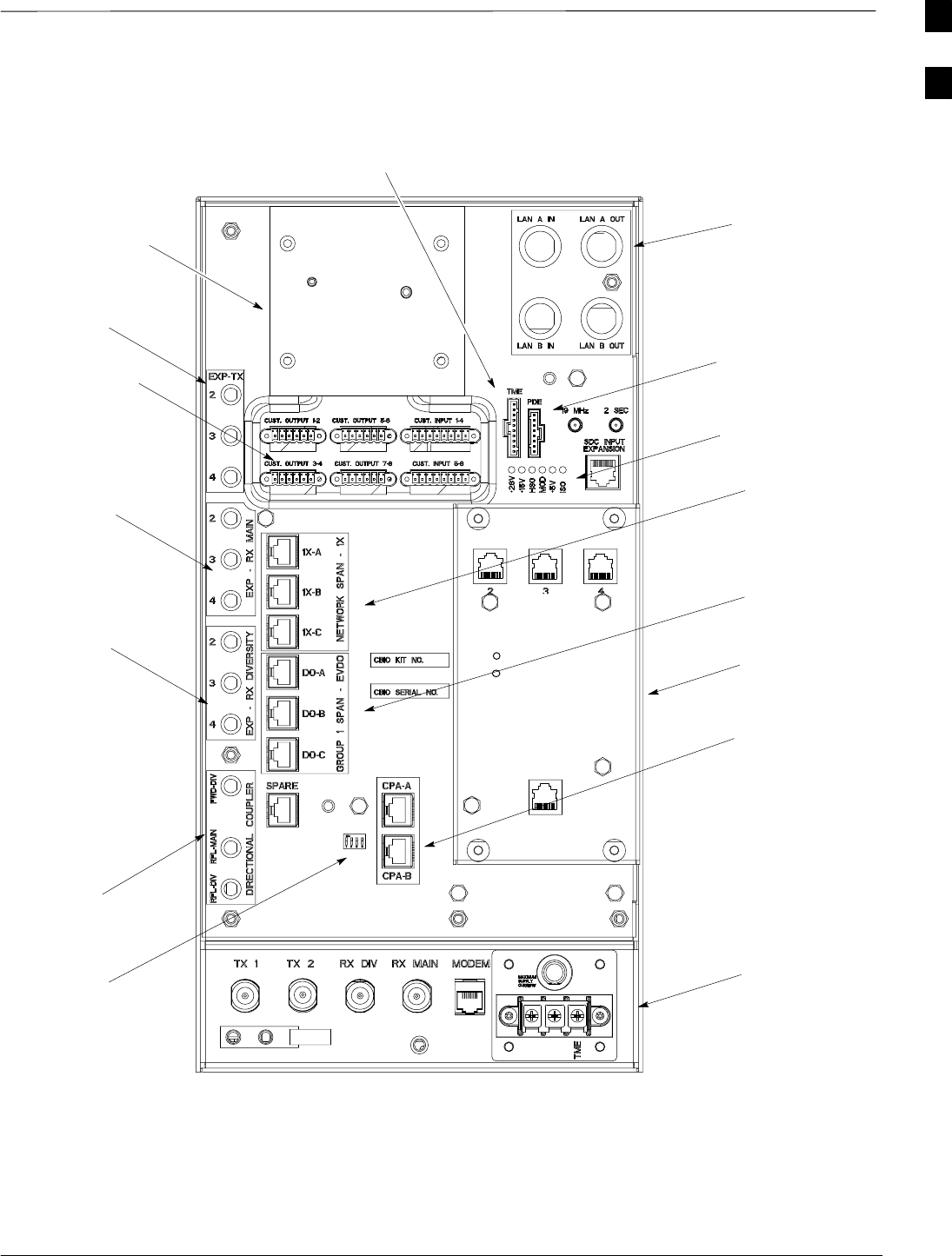
BTS Equipment Identification – continued
Jun 2004 1-27
1X SC480 BTS Hardware Installation, Optimization/ATP, and FRU
DRAFT
Figure 1-7: CBIO Board
ti–cdma–wp–00311–v01–ildoc–ah
RF–GPS LAN
CBIO LEDs
Network Span
1X–A, –B, & –C
Group 1 Span
DO–A, –B, & –C
SDCX
cCLPA
Data A & B
Frame ID
Switch
Directional
Coupler
Expansion RX
Diversity
Expansion RX
Main
Customer
Input/Output
Expansion
TX
PDE Alarm
TME Alarm
See
Figure 1-8
DAISY–CHAIN SYNC – OUT
SDCX KIT NO.
SDCX SERIAL NO.
DAISY–CHAIN POWER
SDCX POWER
EXPANSION FRAME SYNC – OUT
RF–GPS IN
PWR
1
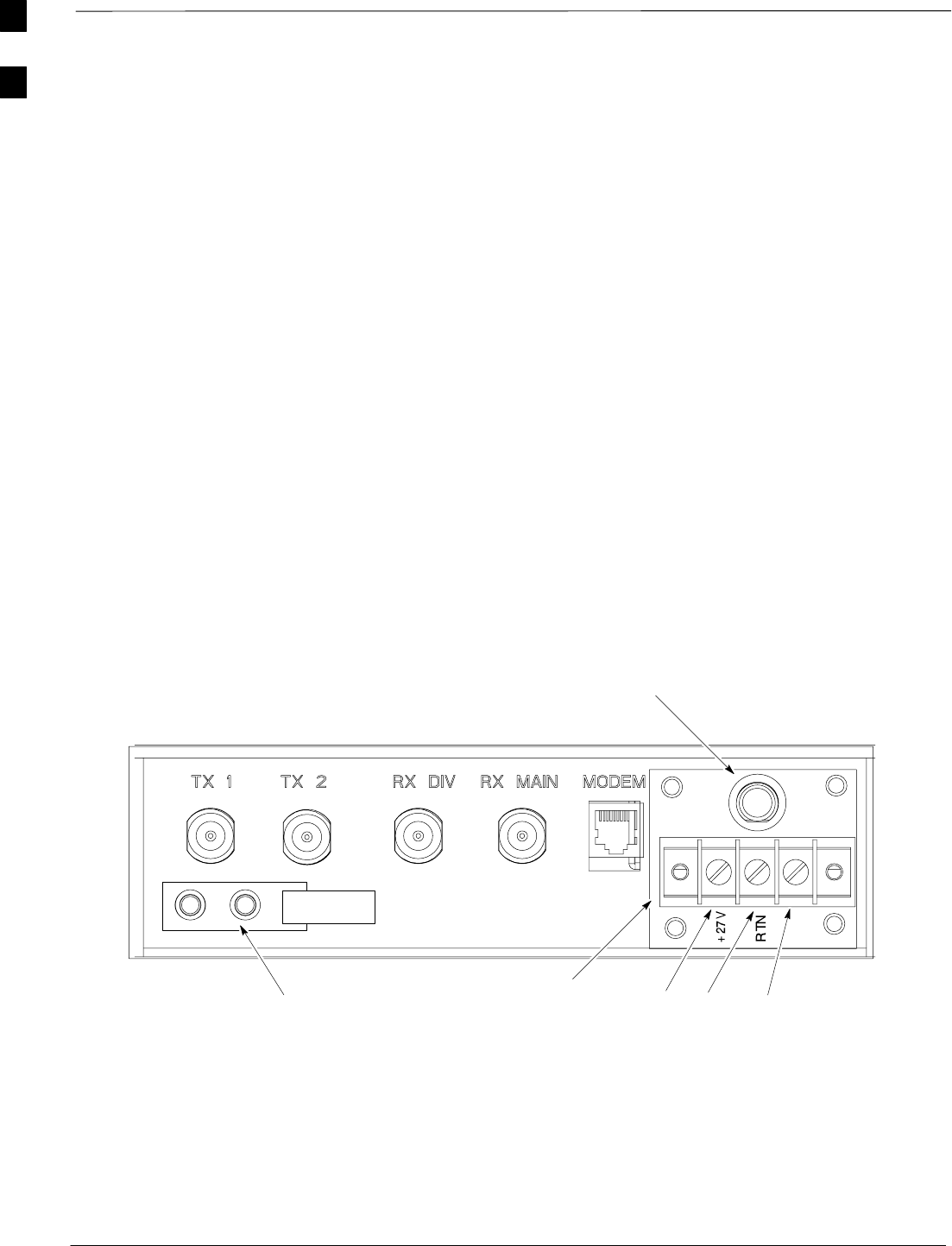
BTS Equipment Identification – continued
DRAFT
1X SC480 BTS Hardware Installation, Optimization/ATP, and FRU Jun 2004
1-28
RF Connectors
Figure 1-8 shows the RF connectors at the rear of the Compact BTS.
Modem Connector
Figure 1-8 shows the Modem connector at the rear of the Compact BTS
(not supported in SC480).
Circuit Breaker
Figure 1-8 shows the location of the +27VDC, 25A circuit breaker,
respectively.
DC Power Connection
Figure 1-8 and Figure 1-8 shows the location of the DC Power Terminal
Strip.
Ground
Figure 1-8 shows the location of the two ground screw holes for the
Compact BTS.
TME
25A
DC Power
Terminal Strip +27 V
RETURN TME
25A Circuit
Breaker
GROUND
(Screw Holes)
Figure 1-8: +27VDC RF Connectors, Circuit Breaker, DC Power Terminal Strip, and
Ground Studs
25
1
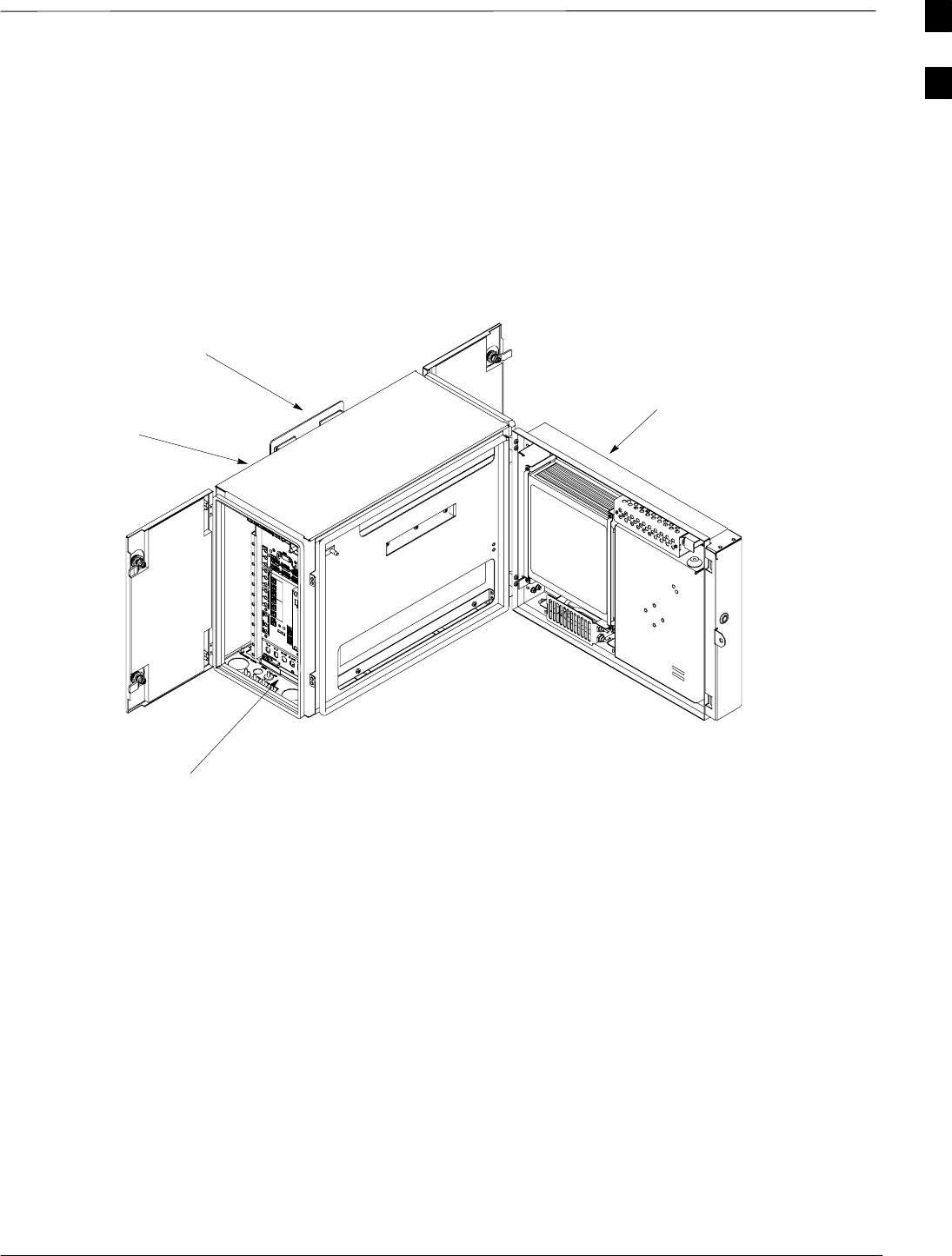
Outdoor Enclosure Equipment Identification
Jun 2004 1-29
1X SC480 BTS Hardware Installation, Optimization/ATP, and FRU
DRAFT
Outdoor Enclosure Equipment
Identification
Figure 1-9 shows the TME and HMS outdoor enclosures.
Figure 1-9: Thermal Managment Enclosure and Heat Manaagement System
Thermal
Management
Enclosure
Compact BTS
Heat Management
System
Wall Mounting
Bracket
Thermal Management
Enclosure
The following are brief descriptions of the components of the TME.
TME
The Thermal Management Enclosure surrounds the Compact BTS,
affording it protection against the weather. See Figure 1-9.
HMS
The Heat Management System attaches to the TME and provides
temperature regulation of the Compact BTS. See Figure 1-9.
PDA
The Power Distribution Assembly is the connection point for the +27
VDC. Also, it contains circuit breakers for the TME and 1U (optional
module). Connections to the HMS and BTS are also provided at the rear
of the unit.. See Figure 1-10.
1
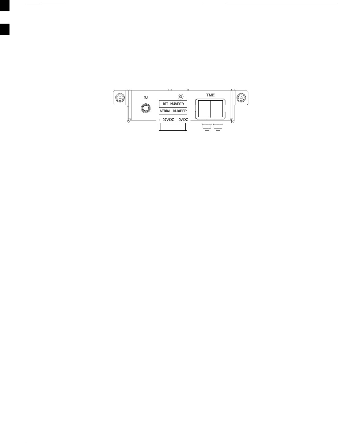
Outdoor Enclosure Equipment Identification – continued
DRAFT
1X SC480 BTS Hardware Installation, Optimization/ATP, and FRU Jun 2004
1-30
Figure 1-10: Power Distribution Assembly
ti–cdma–wp–00350–v01–ildoc–ah
Power Distribution Enclosure
The following are brief descriptions of the components of the PDE.
PDE
The Power Distribution Enclosure converts AC voltage to DC voltage
for use by the TME and Compact Combined Linear Power Amplifier
(cCLPA). Battery backup is routed through the PDE. See Figure 1-11.
SAC Load Center (ACLC) – Where the AC voltage is connected to the
PDE. Also contains AC surge protection.
SPower Supply Module (PSM) – Converts the 220–240 VAC to +27 V
DC for use by the TME, BTS, and cCLPA.
SPower Management Alarm Card (PMAC) – Monitors alarms for PDE
and battery backup.
SCircuit Breakers (CB) – Provides DC surge and DC short circuit
protection.
SPunch Block (PB) – Distribution point for incoming and outgoing
data signal lines.
SMultiple ground connections at the reaar of the PDE
SAntenna surge arrestors slots
HX
The Heat Exchanger attaches to the PDE and provides temperature
regulation.
1
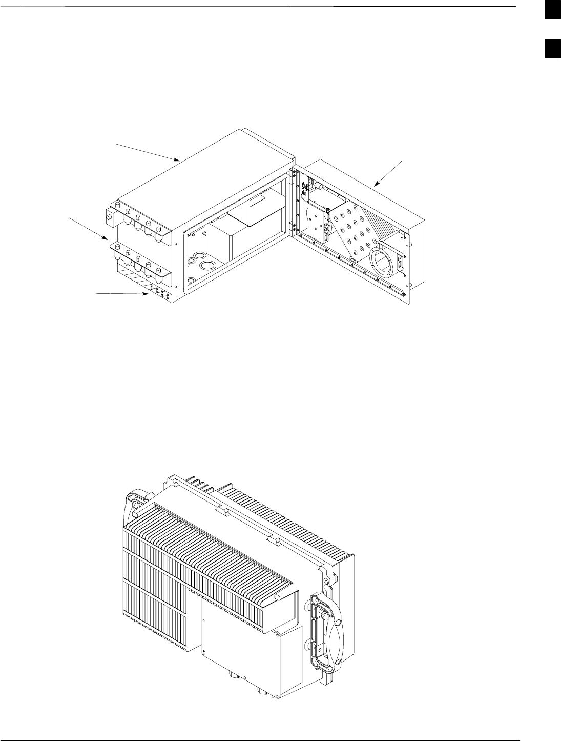
BTS Equipment Identification – continued
Jun 2004 1-31
1X SC480 BTS Hardware Installation, Optimization/ATP, and FRU
DRAFT
Figure 1-11: Power Distribution Enclosure and Heat Exchanger
Heat Exchanger
Power
Management
Enclosure
Antenna Surge
Arrestor Location
Ground
Location
Combined Compact Linear
Power Amplifier
Figure 1-12: Compact Combined Linear Power Amplifier
ti–cdma–wp–00300–v01–ildoc–ah
1

Installation and ATP Order
DRAFT
1X SC480 BTS Hardware Installation, Optimization/ATP, and FRU Jun 2004
1-32
Indoor Installation Order
The pieces of the BTS should be installed in the following order.
1. Unpack and inspect hardware
2. Install mounting hardware and bracket (s)
3. Attach and secure unit to mounting bracket
4. Install GPS
5. Prepare site cabling
6. Attach all ground cabling to unit(s)
7. Attach all cables to unit(s)
Outdoor Installation Order
The pieces of the BTS should be installed in the following order.
1. Unpack and inspect hardware
2. Install mounting hardware
3. Attach and secure units to mounting bracket(s).
4. Attach all ground cabling to unit(s).
5. Prepare site cabling
6. Install GPS.
7. Install antennas
8. Attach AC power cable to PDE
9. Connect DC Power cables between PDE and TME
10. Connect DC power cables between PDE and cCLPA
11. Connect optional Battery Backup cable to PDE
12. Attach all interconnection cables to unit(s).
ATP Order
The following should already be installed on the laptop computer
SWinLMF
The ATP for the BTS is performed in the following sequence:
1. BTS preparation
2. Connecting the LMF computer to the BTS
3. Connecting test equipment to the BTS and LMF
4. Establishing an MMI communications session
5. Setting customer operating channel
6. Synchronization verification
7. Start WinLMF and log on to BTS
8. Update BTS–specific CDF file device load version
9. Download and enable MCC
10. Test equipment setup (Calibration/GPIB address & clock setup)
1

Installation and ATP Order – continued
Jun 2004 1-33
1X SC480 BTS Hardware Installation, Optimization/ATP, and FRU
DRAFT
11. Test equipment selection
12. Power meter calibration
13. Test cable calibration
14. Create CAL file
15. RF path audit
16. TX and RX Acceptance tests
17. Generate an ATP Report
18. Copy WinLMF CAL file to Floppy Disc
19. Terminate LMF session/leave the site
1

Installation and ATP Order – continued
DRAFT
1X SC480 BTS Hardware Installation, Optimization/ATP, and FRU Jun 2004
1-34
Notes
1

Jun 2004 1X SC480 BTS Hardware Installation, Optimization/ATP, and FRU
DRAFT
Chapter 2: Site Preparation
Table of Contents
Site Preparation Overview 2-1 . . . . . . . . . . . . . . . . . . . . . . . . . . . . . . . . . . . . . . . . .
Overview 2-1 . . . . . . . . . . . . . . . . . . . . . . . . . . . . . . . . . . . . . . . . . . . . . . . .
Installation 2-1 . . . . . . . . . . . . . . . . . . . . . . . . . . . . . . . . . . . . . . . . . . . . . . .
Verifications and procedures 2-1 . . . . . . . . . . . . . . . . . . . . . . . . . . . . . . . . .
Site manager 2-1 . . . . . . . . . . . . . . . . . . . . . . . . . . . . . . . . . . . . . . . . . . . . .
Verifications and inspections 2-1 . . . . . . . . . . . . . . . . . . . . . . . . . . . . . . . . .
Site Inspections 2-2 . . . . . . . . . . . . . . . . . . . . . . . . . . . . . . . . . . . . . . . . . . . . . . . . . .
Inspection overview 2-2 . . . . . . . . . . . . . . . . . . . . . . . . . . . . . . . . . . . . . . . .
Deficiencies 2-2 . . . . . . . . . . . . . . . . . . . . . . . . . . . . . . . . . . . . . . . . . . . . . .
What to Inspect 2-2 . . . . . . . . . . . . . . . . . . . . . . . . . . . . . . . . . . . . . . . . . . .
Antenna and Transmission Line Inspections 2-2 . . . . . . . . . . . . . . . . . . . . .
Structural Inspections and Verifications 2-2 . . . . . . . . . . . . . . . . . . . . . . . .
Grounding Inspections 2-4 . . . . . . . . . . . . . . . . . . . . . . . . . . . . . . . . . . . . . .
Prepare Site for the Arrival of the Equipment 2-5 . . . . . . . . . . . . . . . . . . . . . . . . . .
Description 2-5 . . . . . . . . . . . . . . . . . . . . . . . . . . . . . . . . . . . . . . . . . . . . . . .
Equipment Arrival 2-5 . . . . . . . . . . . . . . . . . . . . . . . . . . . . . . . . . . . . . . . . .
Securing Fluorescent Lights 2-5 . . . . . . . . . . . . . . . . . . . . . . . . . . . . . . . . .
Procedure to Prepare the Site for the Equipment 2-6 . . . . . . . . . . . . . . . . . .
Unpacking the Equipment 2-7 . . . . . . . . . . . . . . . . . . . . . . . . . . . . . . . . . . . . . . . . .
Description 2-7 . . . . . . . . . . . . . . . . . . . . . . . . . . . . . . . . . . . . . . . . . . . . . . .
How Equipment is Shipped 2-7 . . . . . . . . . . . . . . . . . . . . . . . . . . . . . . . . . .
How Equipment Arrives 2-7 . . . . . . . . . . . . . . . . . . . . . . . . . . . . . . . . . . . .
Securing Fluorescent Lights 2-7 . . . . . . . . . . . . . . . . . . . . . . . . . . . . . . . . .
Unpacking Process 2-7 . . . . . . . . . . . . . . . . . . . . . . . . . . . . . . . . . . . . . . . . .
Recommended Tools 2-7 . . . . . . . . . . . . . . . . . . . . . . . . . . . . . . . . . . . . . . .
Unpacking Diagrams 2-8 . . . . . . . . . . . . . . . . . . . . . . . . . . . . . . . . . . . . . . .
Unpacking a Cardboard or Wood Container 2-11 . . . . . . . . . . . . . . . . . . . . .
Removing Outdoor Equipment from a Container 2-11 . . . . . . . . . . . . . . . . .
Removing Indoor Equipment from a Container 2-13 . . . . . . . . . . . . . . . . . .
Dimensions and Clearances 2-14 . . . . . . . . . . . . . . . . . . . . . . . . . . . . . . . . . . . . . . . .
BTS Overview 2-14 . . . . . . . . . . . . . . . . . . . . . . . . . . . . . . . . . . . . . . . . . . . .
Dimensions and Clearances 2-14 . . . . . . . . . . . . . . . . . . . . . . . . . . . . . . . . . .
BTS Dimensions 2-15 . . . . . . . . . . . . . . . . . . . . . . . . . . . . . . . . . . . . . . . . . .
cCLPA Dimensions and Clearances 2-16 . . . . . . . . . . . . . . . . . . . . . . . . . . .
Unit Clearances 2-18 . . . . . . . . . . . . . . . . . . . . . . . . . . . . . . . . . . . . . . . . . . .
TME Dimensions and Clearances 2-20 . . . . . . . . . . . . . . . . . . . . . . . . . . . . .
2

Table of Contents – continued
1X SC480 BTS Hardware Installation, Optimization/ATP, and FRU Jun 2004
DRAFT
TME Clearances 2-22 . . . . . . . . . . . . . . . . . . . . . . . . . . . . . . . . . . . . . . . . . .
PDE Dimensions and Clearances 2-23 . . . . . . . . . . . . . . . . . . . . . . . . . . . . .
PDE Clearances 2-25 . . . . . . . . . . . . . . . . . . . . . . . . . . . . . . . . . . . . . . . . . . .
Outdoor Clearances 2-25 . . . . . . . . . . . . . . . . . . . . . . . . . . . . . . . . . . . . . . . .
2

Site Preparation Overview
Jun 2004 2-1
1X SC480 BTS Hardware Installation, Optimization/ATP, and FRU
DRAFT
Overview
This chapter provides the procedures and information to verify that the
site is ready to have the equipment installed. It also provides procedures
to ensure the safety of the installation personnel, protect the equipment
from damage, and verify the site layout parameters.
Installation
This SCt480 BTS can be installed indoors or outdoors. The site
preparation depends on the type of installation and the site
characteristics. Battery back up is optional and provided by the
customer.
Verifications and procedures
The verifications and procedures provided in this chapter are:
SInternal site inspections
SPreparing site for the arrival of equipment
SSite layout verification
Site manager
The site manager is the person in charge of and responsible for the full
site.
Verifications and inspections
Verifications typically have the installer check with the site manager that
a condition has been previously checked or procedure previously
performed and meets a stated specification.
Inspections typically have the installer personally checking that a
condition or item meets stated specifications.
2

Site Inspections
DRAFT
1X SC480 BTS Hardware Installation, Optimization/ATP, and FRU Jun 2004
2-2
Inspection overview
Inspect the site to verify that the necessary equipment has been properly
installed. Also, as part of the inspection, verify that the equipment is
adequate to support the Motorola equipment. Not all inspections may
apply to every site. The site characteristics determine which inspections
apply.
Installation of ancillary equipment (e.g., power supplies,
terminal blocks, etc.) may be the responsibility of the
installer. Refer questions to your Motorola Program
Manager.
NOTE
Deficiencies
Notify responsible personnel of any deficiencies as soon as possible, if
the installer is not responsible for correcting the noted deficiencies.
Deficiencies may need to be corrected before any installation can start.
What to Inspect
The following external items should be inspected and compared against
any related site-specific documentation.
SAntennas
SExternal ground systems
SClearances for units
SMounting Structures
Additionally, for all sites the incoming power should be inspected and
compared against any related site-specific documentation.
Antenna and Transmission
Line Inspections
Documentation
The vendor(s) responsible for supplying other equipment have left
installation documentation at the site. Review this documentation and
compare it with any related site-specific documents.
Inspection
Inspect the following:
SAntenna and transmission line installation
SGrounding.
Structural Inspections and
Verifications
Site power
Verify with the site manager that site power has been previously checked
and meets the specifications stated in the site-specific documentation.
2
Site Inspections – continued
Jun 2004 2-3
1X SC480 BTS Hardware Installation, Optimization/ATP, and FRU
DRAFT
Cabling rack
Inspect the cable rack for proper installation. The cable racks should be
at least 7 ft from the floor. The cable racks should be electrically tied
together with 6 AWG wire, except cable racks that are in an isolated
ground zone.
Fire protection
For indoor installations verify with the site manager that some type of
fixed fire suppression equipment is installed. The possible types are:
SHalon gas system, recommended for cell sites because:
– Halon extinguishes a fire without removing oxygen from a room.
– Halon is clean, allowing for quick cleanup after a fire.
– Halon will not damage the cell site equipment.
SCO2 (carbon dioxide) system.
SSprinkler system. “Dry pipe” sprinkler systems that remove all power
to a room before filling the overhead sprinklers with water are
recommended.
In addition to the fixed fire suppression equipment, there
should be at least two 5-lb ABC class portable fire
extinguishers on the premises before equipment installation
begins.
WARNING
Fire Fighting Procedures
Cellular infrastructure equipment contains various materials which can
decompose into toxic compounds during intense heat. When fire
fighting conditions are severe, wear full protective clothing, including
helmet, self–contained, positive pressure or pressure demand breathing
apparatus, bunker coat and pants, bands around arms, waist and legs,
face mask, and protective covering for exposed areas of the head.
Antenna cables and ports
Inspect the antenna cables and ports to verify that:
SAll antenna cables have been properly labeled.
SAntenna ports have been properly weatherproofed.
SAn adequate number of ports exist to handle all of the required
antenna runs.
SLightning arrestors have been installed at the building or shelter entry
point.
SFor some systems, special ports may be required (refer to the
site-specific information for further details).
2
Site Inspections – continued
DRAFT
1X SC480 BTS Hardware Installation, Optimization/ATP, and FRU Jun 2004
2-4
Grounding Inspections
Indoor installations
For indoor installations refer to the Grounding Guideline for Cellular
Radio Installations (68P81150E62) for all grounding inspection
procedures.
Verify the following:
SAll ground cables have a bend radius of 20 cm (8 inches) or more.
SMetallic lines (span, phone[modem], RGPS, power and antenna) that
enter or leave the site should be equipped with a 3-electrode gas tube
protector. The ground side of the gas tubes should be tied to the
Master Ground Bus (MGB).
SAll installed cable racks (in the same ground zone) are jumpered
together.
Cable racks in an Isolated Ground Zone (IGZ) are not to be
connected to a cable rack in a non-IGZ. For more
information on IGZ, see Grounding Guideline for Cellular
Radio Installations, Motorola part number 68P81150E62
or Appendix C of Standards and Guidelines for
Communications Sites (Motorola part number
9882904Y01)
WARNING
Outdoor Installations
For outdoor installations refer to the Grounding Guideline for Cellular
Radio Installations (Motorola part number 68P81150E62) or Appendix
C of Standards and Guidelines for Communications Sites (Motorola part
number 9882904Y01) for all grounding inspection procedures.
Verify the following:
SAll outdoor enclosures are grounded to system masrter ground.
SAll enclosures have conduit attached.
SIt is recommended that all metallic lines (span, RGPS, power, and
antenna) that enter or leave the site are be equipped with a surge
suppression device (lightning arrestor).
2
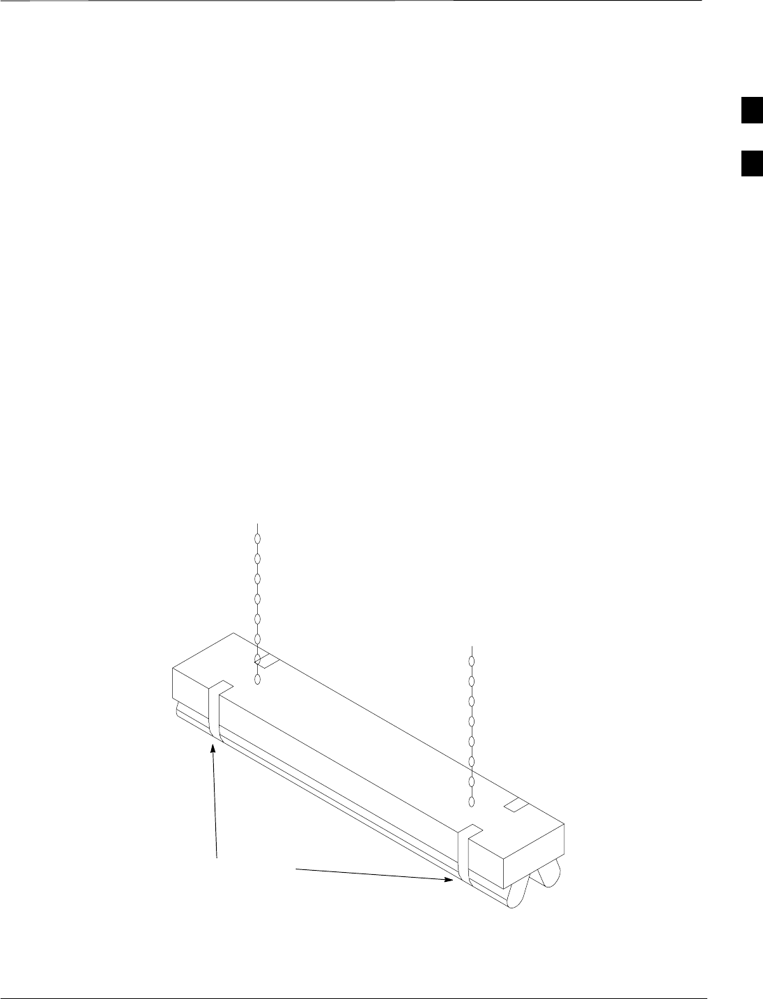
Prepare Site for the Arrival of the Equipment
Jun 2004 2-5
1X SC480 BTS Hardware Installation, Optimization/ATP, and FRU
DRAFT
Description
This information covers various topics not all of which are needed at
every site. Based on the site characteristics execute the steps that apply
to your site. Before installing the equipment, do the following to ensure
the safety of installation personnel and to protect the equipment.
Equipment Arrival
Before the equipment arrives, indicate to the transport company an area
at the site where the equipment can be unloaded and, if necessary,
unpacked. The equipment should be carefully delivered to the site, along
with all equipment dollies and padding required to safely move the
equipment from the unloading area to the cell site. The following should
also be provided, outdoor weather protection, temporary lighting and
power for lighting and power tools.
Securing Fluorescent Lights
Figure 2-1 illustrates the use of tape to secure fluorescent tubes. Secure
any fluorescent tubes that may be hit or damaged by any unit, cable, or
personnel.
Figure 2-1: Securing Lights with Tape
Apply masking tape to keep
fluorescent tubes in place in
the fixtures. 0150–O_IL.doc
2

Prepare Site for the Arrival of the Equipment – continued
DRAFT
1X SC480 BTS Hardware Installation, Optimization/ATP, and FRU Jun 2004
2-6
Procedure to Prepare the Site
for the Equipment
Table 2-1: Procedure to Prepare the Site for the BTS
Step Action
1If some type of protective padding is available install it around any existing equipment at the site that
could be damaged during installation of the unit(s).
2Hang plastic sheets around intended work areas to prevent dust and debris from damaging co-located
equipment during installation.
3Secure any fluorescent tubes in place using masking tape. (Refer to Figure 2-1.)
NOTE
This will prevent the tubes from being inadvertently jarred from the fixtures during the installation of
equipment or cables.
4Locate the demarcation blocks for external utilities.
Verify that they are shown on the Site Engineering documents, and determine the required cable
routing back to the equipment frames.
5Verify the following:
SDC power is available and meets the site documentation specifications (if applicable).
SCable rack is installed per site document specifications.
SOutdoor cable runs are installed and meet local building codes.
SSpan line termination tie points are available.
SCustomer input termination tie points are available.
SThere is clear access to move the equipment to the desired mounting area.
SThere is sufficient space for installation and service access to the equipment.
SCustomer supplied shelters are installed.
2

Unpacking the Equipment
Jun 2004 2-7
1X SC480 BTS Hardware Installation, Optimization/ATP, and FRU
DRAFT
Description
The Purpose of this section is to describe how the SC480 Compact BTS,
TME, PDE, and cCLPA are packaged for shipping and how to correctly
unpack the units in preparation for installation.
How Equipment is Shipped
The equipment are shipped in either cardboard or wood containers. The
equipment are shipped with all internal cabling installed. For an indoor
installation, the BTS is shipped in a single container. BTS accessories
are shipped in their own container. If used, the cCLPA and accessories
are shipped in a single container. Also, the Mounting Plate and BTS
Mounting Bracket are shipped in a separate container.
For an outdoor configuration, the Thermal Management Enclosure
(TME) and Wall Mounting Bracket are shipped in a single containter.
The Base Transceiver Station (BTS) is shipped in a separate container.
BTS accessories are packed separately and shipped in a container. The
Power Distribution Enclosure (PDE), and Compact Combined Linear
Power Amplifier (cCLPA) with their respective accessories, are shipped
in separate containers.
Conduit piping and batteries for backup power are customer supplied.
How Equipment Arrives
Before the equipment arrives, indicate to the transport company an area
at the site where the equipment can be unloaded and, if necessary,
unpacked. The equipment should be carefully delivered to the site, along
with all equipment dollies and padding required to safely move the
equipment from the unloading area to the cell site. The following should
also be provided, outdoor weather protection, temporary lighting and
power for lighting and power tools.
Securing Fluorescent Lights
For indoor configuration, Figure 2-1 illustrates the use of tape to secure
fluorescent tubes. Secure any fluorescent tubes that may be hit or
damaged by any unit, cable, mechanical lift, or personnel.
Unpacking Process
The unpacking process requires that the following procedures be
completed in the order shown:
1. Unpack the shipping container
2. Inventory the shipping container
3. Inspect equipment for damage
Recommended Tools
The tools in Table 2-2 are recommended to assist in opening the
containers housing the equipment.
2
Unpacking the Equipment – continued
DRAFT
1X SC480 BTS Hardware Installation, Optimization/ATP, and FRU Jun 2004
2-8
Table 2-2: Recommended Unpacking Tools
Qty Description
1Tin Snips
2Knife, Box Cutter, or Scissors
Unpacking Diagrams
The following diagrams show how to unpack the equipment.
The steel bands surrounding the container can spring out
from the container when the bands are cut. To avoid
personal injury, stand safely to one side of the bands while
cutting.
The approximate weights of the containers (with
packaging):
TME: 50 kgs (100 lbs)
BTS: 30 kgs (150 lbs)
PDE :40 kgs (85 lbs)
cCLPA: 22 kgs (48 lbs).
Mounting Plate/BTS Mounting Bracket: 7 kgs (15 lbs).
WARNING
2
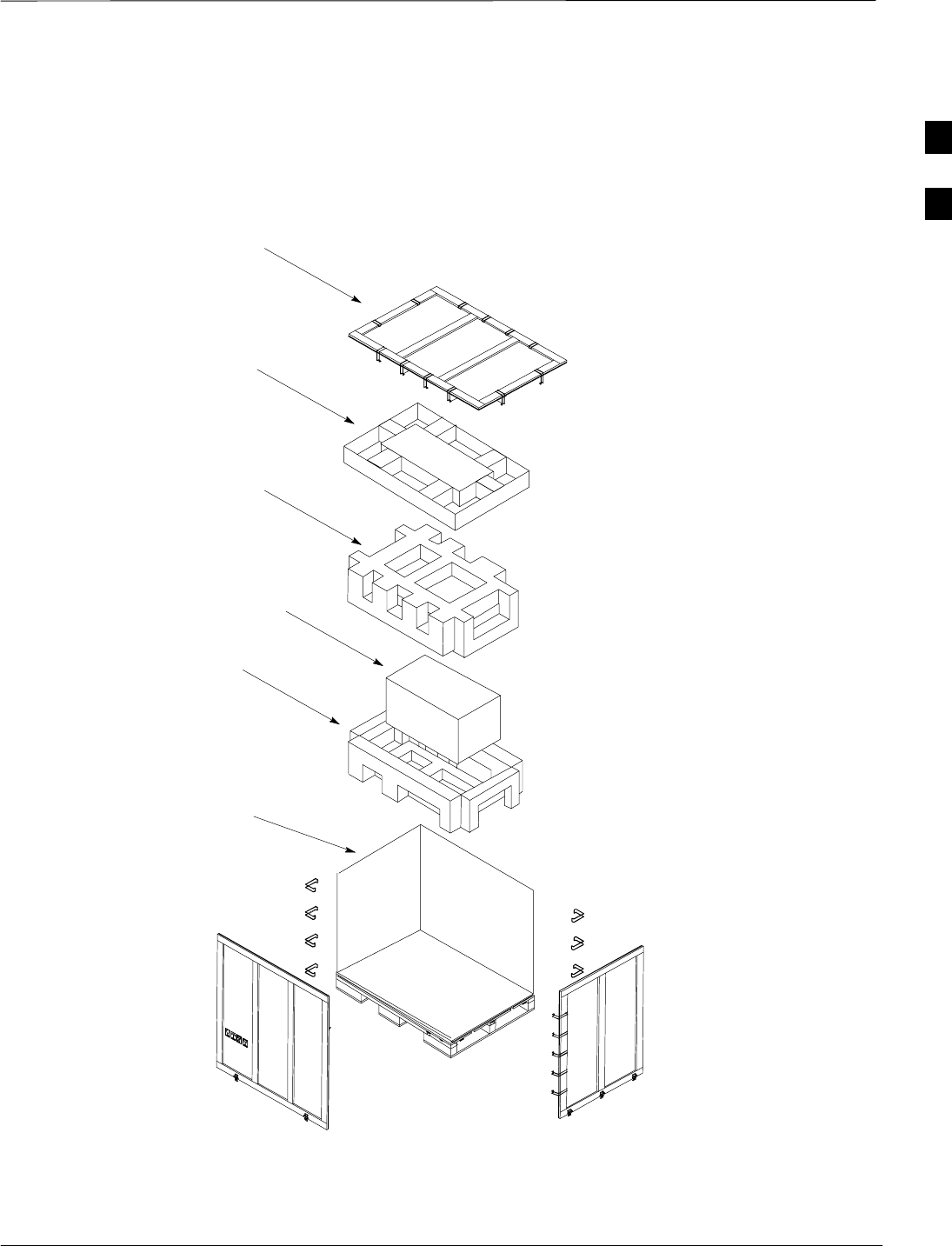
Unpacking the Equipment – continued
Jun 2004 2-9
1X SC480 BTS Hardware Installation, Optimization/ATP, and FRU
DRAFT
Figure 2-2: Wood Shipping Container
ti–cdma–wp–00347–v02–ildoc–ah
Wood Crate
Styrofoam
Packing
Styrofoam
Packing
Wall Mounting
Bracket
container
Wood Crate
Top
TME
NOTE:
1. Normally this styrofoam
packing is attached to the
pallet. it is shown exploded
for clarity
2. This example shows the TME
shipping container.
2
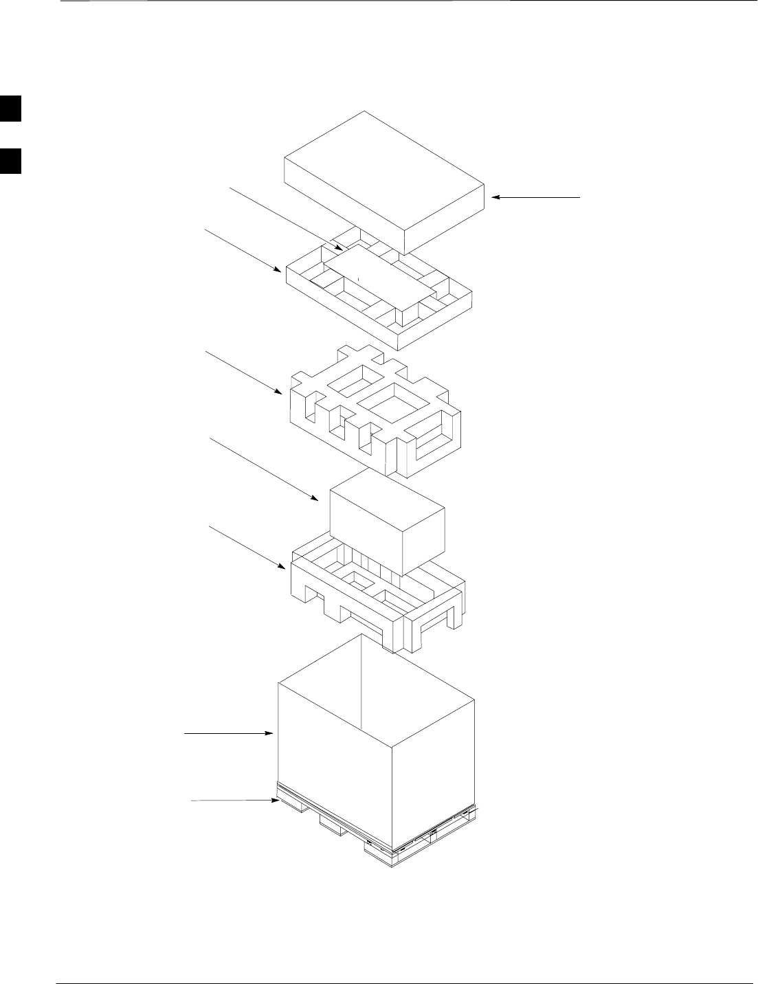
Unpacking the Equipment – continued
DRAFT
1X SC480 BTS Hardware Installation, Optimization/ATP, and FRU Jun 2004
2-10
Figure 2-3: Cardboard Shipping Container
NOTE:
1. Normally this styrofoam
packing is attached to the
pallet. it is shown exploded
for clarity
2. This example shows the TME
shipping container.
ti–cdma–wp–00347–v01–ildoc–ah
Styrofoam
Packing1
Cardboard
Box
TME
Styrofoam
Packing
Insert with
Packing
Wall Mounting
Bracket
cardboard Box Cardboard Lid
Wood Pallet
2

Unpacking the Equipment – continued
Jun 2004 2-11
1X SC480 BTS Hardware Installation, Optimization/ATP, and FRU
DRAFT
Unpacking a Cardboard or
Wood Container
Follow the procedure in Table 2-3 to unpack equipment from a container.
Table 2-3: Unpacking Equipment from a Cardboard or Wood Container
Step Action
1Inspect the container for damage.
Cardboard Container
2Open container using tin snips to cut each outer steel band or a knife (or equivalent) to cut the plastic
wrap that surrounds the container.
3Remove equipment door key from top of container.
4Lift off the cardboard cover.
5Proceed to Table 2-4 or Table 2-5.
Wood Container
6Perform step 1.
7Loosen latches at the bottom of the container.
8Remove clips holding the top pallet , and remove pallet from the container.
9Remove equipment door key from pallet.
10 Proceed to Table 2-4 or Table 2-5.
Removing Outdoor Equipment
from a Container
Follow the procedure in Table 2-4 to remove the outdoor equipment
from a container. The following procedure starts with the TME removal
and continues through to the Pole Mounting Assembly. The order of
opening containers is not important, it is just for demonstration
purposes. The procedure is written for one set. Perform procedure as
many times as required to accommodate the site configuration.
Table 2-4: Procedure to Remove Outdoor Equipment from Container
Step Action
1Open shipping container holding TME. Perform Table 2-3.
2Remove the box containing the Wall Mounting Bracket from the insert.
3Remove insert.
4Remove cage style packing material surrounding the TME.
5Using a knife or equivalent, carefuly cut through protective bag enclosing TME.
2

Unpacking the Equipment – continued
DRAFT
1X SC480 BTS Hardware Installation, Optimization/ATP, and FRU Jun 2004
2-12
Table 2-4: Procedure to Remove Outdoor Equipment from Container
Step Action
n WARNING
The TME and HMS are shipped as one unit. Together they weigh 39 kg (86 lbs). It is recommended
that the HMS be removed first; otherwise, two people are required to remove the TME with HMS
installed.
6Use the key to unlock the HMS and open.
7Use a wrench to remove two nuts and washers securing ground cable to HMS.
8Disconnect signal cable from TME.
9Remove HMS from TME hinges and place on a flat surface.
10 Remove TME and place on its backside on a flat surface.
11 Open shipping container holding PDE. Perform Table 2-3.
12 Remove box containing the Wall Mounting Bracket from insert.
13 Remove insert.
n WARNING
The PDE and HX are shipped as one unit. Together they weigh 52 kg (115 lbs). It is recommended
that a minimum of two people be required to remove the PDE with HX installed.
13a Remove PDE and place on its backside on a flat surface.
14 Open shipping container holding cCLPA. Perform Table 2-3.
! CAUTION
Be careful not to damage the cooling fins on the cCLPA.
14a Remove cCLPA and place on its backside on a flat surface.
15 Remove associated accessories and place on a flat surface.
16 Open shipping container holding BTS. Perform Table 2-3.
17 Remove box containing RGPS or Local GPS (RF–GPS) antenna and cabling, and place on a flat
surface.
NOTE
RGPS or RF–GPS may have been shipped in a separate container.
18 Remove packing surrounding BTS.
19 Remove BTS and place on a flat surface.
20 If system is to be pole mounted proceed to step 21; otherwise, proceed to step 23.
21 Open shipping container holding Pole Mounting Assembly.
22 Remove Pole Mounting Bracket Assembly from container and set on a flat surface.
23 Take inventory of equipment received. Report the extent of any equipment damage to the transport
company and to appropriate management personnel.
2

Unpacking the Equipment – continued
Jun 2004 2-13
1X SC480 BTS Hardware Installation, Optimization/ATP, and FRU
DRAFT
Removing Indoor Equipment
from a Container
Follow the procedure in Table 2-5 to remove the indoor equipment from
a container. The following procedure starts with the BTS removal and
continues through to the Mounting Plate. The order of opening
containers is not important, it is just for demonstration purposes. The
procedure is written for one set. Perform procedure as many times as
required to accommodate the site configuration.
Table 2-5: Procedure to Remove Indoor Equipment from Container
Step Action
1Inspect containers for damage. Use tin snips or knife to cut straps holding Mounting Plate container to
the BTS container.
2Open container holding Mounting Plate and accessories.
3Remove Mounting Plate and accessories and place on a flat surface.
4Open shipping container holding BTS.
5Remove box containing RGPS or Local GPS (RF–GPS) antenna and cabling, and place on a flat
surface.
6Remove insert.
7Remove packing surrounding BTS.
8Remove BTS and place on a flat surface.
NOTE
If a cCLPA has also been shipped, proceed to step 9; otherwise, proceed to step 12.
9Open shipping container holding cCLPA. Perform Table 2-3.
10 Remove packing surrounding cCLPA.
! CAUTION
Be careful not to damage the cooling fins on the cCLPA.
11 Remove cCLPA and place on a flat surface.
12 Take inventory of equipment received. Report the extent of any equipment damage to the transport
company and to appropriate management personnel.
2

Dimensions and Clearances
DRAFT
1X SC480 BTS Hardware Installation, Optimization/ATP, and FRU Jun 2004
2-14
BTS Overview
This information covers the dimensions and clearances associated with
the BTS for indoor configurations.
Dimensions and Clearances
Table 2-6, Table 2-7, and Figure 2-4 through Figure 2-7 show the
installed dimensions and recommended clearances for each item.
Table 2-6: Installation Dimensions for the BTS
Item Height Width Depth Weight
BTS
(fully
installed)
425 mm
(17 in.)
218 mm
(9 in.)
626 mm
(25 in.)
23 kg
(50 lbs)
Table 2-7: Minimum Clearances for the BTS
Item Front Back Left Right Top Bottom
Installation and
Maintenance
Requirements
680 mm
(27 in.) 400 mm
(16 in.) 50 mm
(2 in.) 50 mm
(2 in.) 50 mm
(2 in.) 0 mm
(0 in.)
Functional
Requirements 50 mm
(2 in.) 50 mm
(2 in.) 50 mm
(2 in.) 50 mm
(2 in.) 50 mm
(2 in.) 0 mm
(0 in.)
2
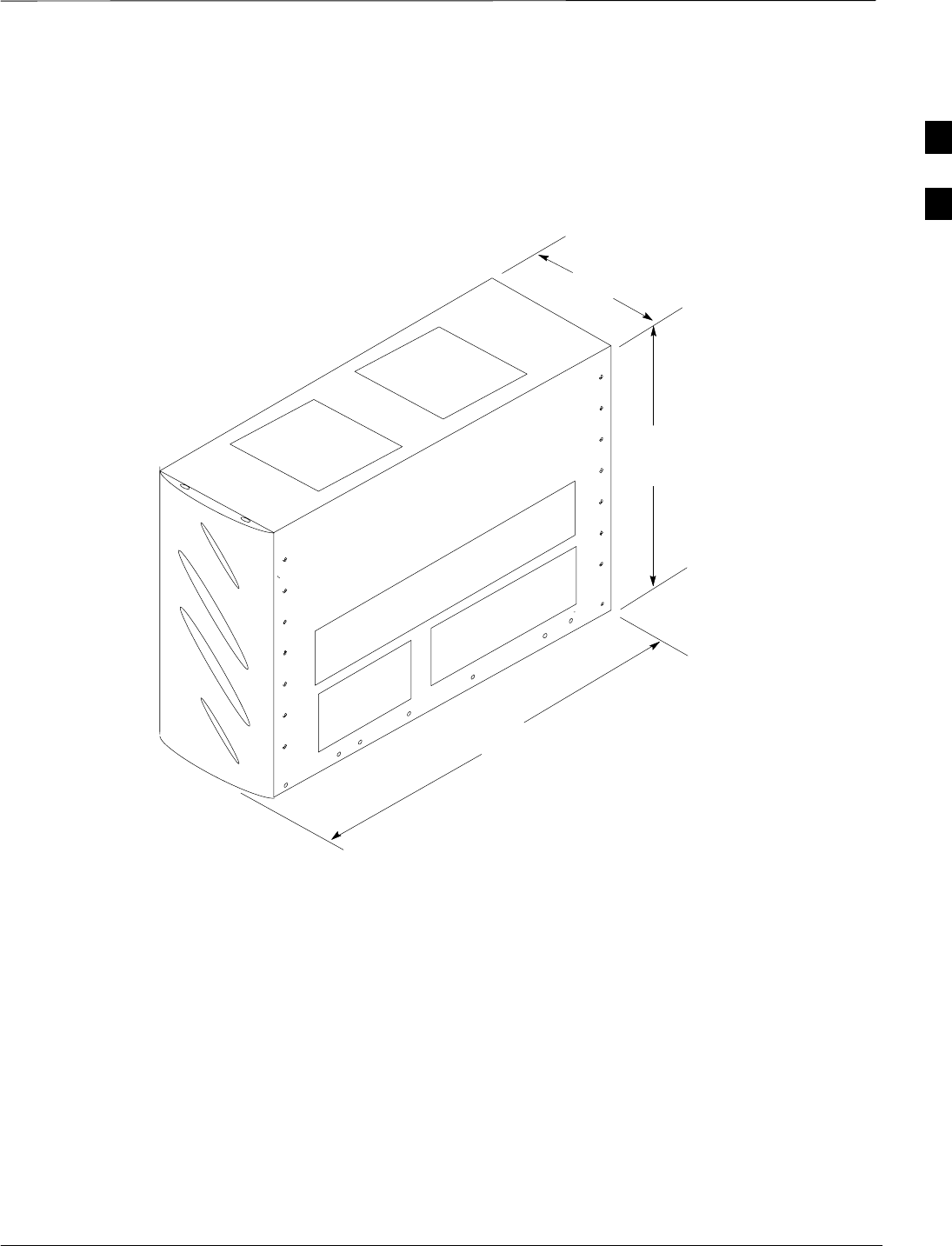
Dimensions and Clearances – continued
Jun 2004 2-15
1X SC480 BTS Hardware Installation, Optimization/ATP, and FRU
DRAFT
BTS Dimensions
The BTS dimensions are shown below.
Figure 2-4: Overall Dimensions of BTS
218 mm
425 mm
626 mm
Front cover installed
ti–cdma–wp–00302–v01–ildoc–ah
2
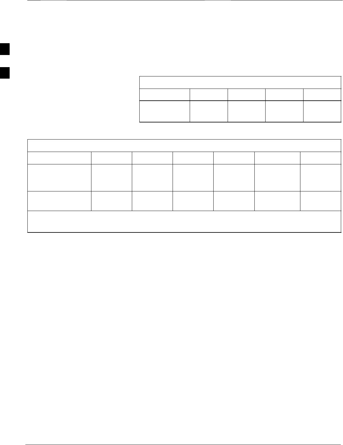
Dimensions and Clearances – continued
DRAFT
1X SC480 BTS Hardware Installation, Optimization/ATP, and FRU Jun 2004
2-16
cCLPA Dimensions and
Clearances
Table 2-8, Table 2-9, and Figure 2-5 show the installed dimensions and
recommended clearances for each item.
Table 2-8: Installation Dimensions for the cCLPA
Item Height Length Width Weight
cCLPA 261 mm
(10 in.)
495 mm
(19 in.)
295 mm
(12 in.)
20 kg
(44 lbs)
Table 2-9: Minimum Clearances for the cCLPA
Item Front Back Left Right Top Bottom
Installation and
Maintenance
Requirements
680 mm
(27 in.) 0 mm
(0 in.) *150 mm
(6 in.) *150 mm
(6 in.) 100 mm
(4 in.) **500 mm
(20 in.)
Functional
Requirements 680 mm
(27 in.) 0 mm
(0 in.) 150 mm
(6 in.) 150 mm
(6 in.) 100 mm
(4 in.) 500 mm
(20 in.)
* Dimension shown accommodates the handles. Without handles 0 mm is the minimum.
** Minimum of 1 M (40 in) for ground clearance.
2
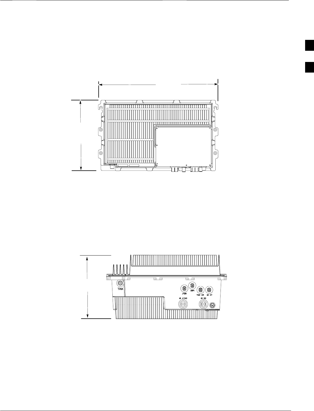
Dimensions and Clearances – continued
Jun 2004 2-17
1X SC480 BTS Hardware Installation, Optimization/ATP, and FRU
DRAFT
Figure 2-5: cCLPA Dimensions and Functional Clearances
295.0 mm
487.0 mm
260.0 mm
Bottom Clearance
500 mm minimum
Top Clearance
100 mm minimum
ti–cdma–wp–00301–v01–ildoc–ah
NOTE:
Overall length of cCLPA is from
mounting flange to mounting
flange.
Front Clearance
680 mm minimum
Rear Clearance
0 mm minimum
Side Clearance
150 mm minimum
Side Clearance
150 mm minimum
Bottom Clearance
1 M minimum above
ground
2
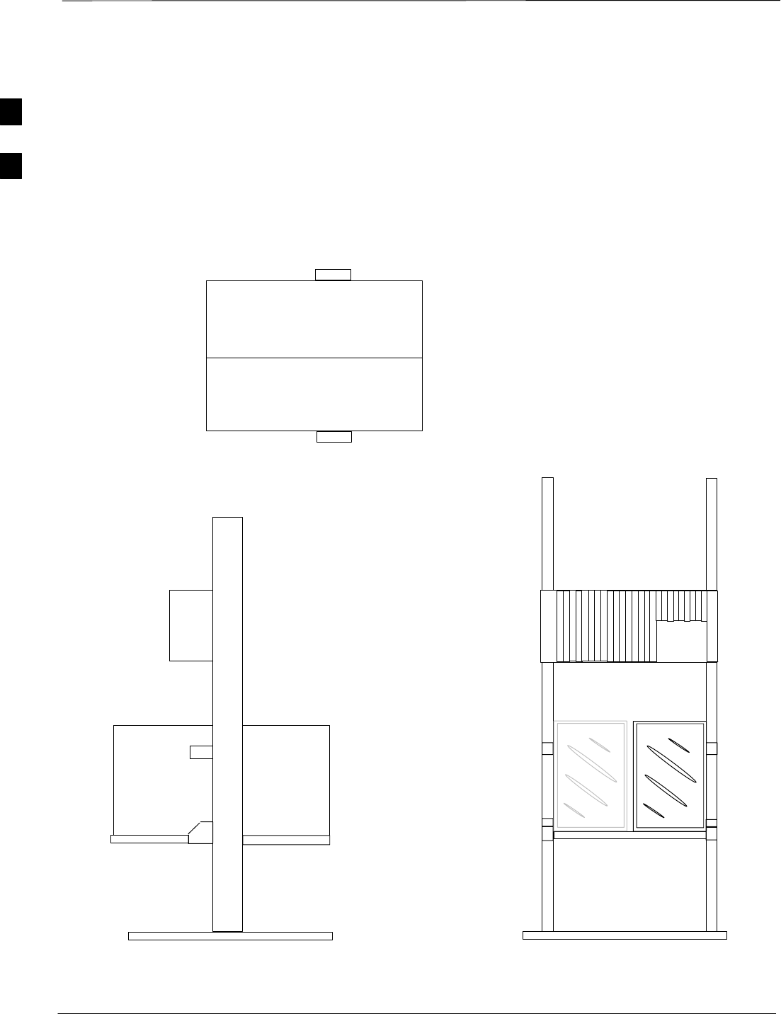
Dimensions and Clearances – continued
DRAFT
1X SC480 BTS Hardware Installation, Optimization/ATP, and FRU Jun 2004
2-18
Unit Clearances
The unit clearances are shown below.
Figure 2-6: Indoor Functional Clearances for BTS
Top View
Side View
NOTE:
For access to RF filter
tray, remove BTS from
the shelf.
Front View
Compact BTS
Mounting Plate
Side Clearance
50 mm minimum
Side Clearance
50 mm minimum
Rear Clearance
50 mm minimum
Front Clearance
50 mm minimum
100 mm minimum
clearance
125 mm minimum
clearance
NOTE:
If there is only one cCLPA, then
the top clearance is 100 mm (4
in.) minimum. The clearance
above a single BTS is 125 mm (5
in.) minimum.
For two BTSs the clearance is
250 mm (10 in.) minimum. See
Figure 2-7.
If two cCLPAs are used, the
clearance between them is 625
mm (20 in.) minimum. See
Figure 2-7.
BTS can be mounted
on either side of the
mounting plate
2
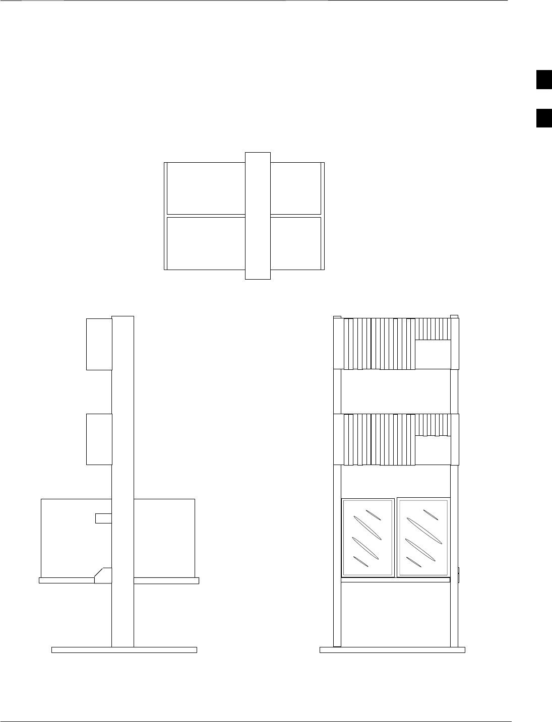
Dimensions and Clearances – continued
Jun 2004 2-19
1X SC480 BTS Hardware Installation, Optimization/ATP, and FRU
DRAFT
Figure 2-7: Indoor Functional Clearances for BTS Side–By–Side Configuration
Rear Clearance
50 mm minimum
Top View
Side View
Side Clearance
50 mm minimum
NOTE:
For access to RF filter tray
remove BTS from the shelf.
Seated side–by–side on the
mounting plate does not interfere
with BTS ventilation.
Front View
Front Clearance
50 mm minimum
Side Clearance
50 mm minimum
625 mm minimum
clearance
250 mm minimum
clearance
NOTE:
The 100 mm (4 in.) clearance above
the cCLPA only applies if there is a
single cCLPA present.
If two cCLPAs are used, the clearance
between the cCLPAs is 625 mm (25 in. )
minimum.
NOTE:
Normal clearance for cCLPA above
BTS is 125 mm (5 in.) minimum.
If two BTSs are used, the clearance
is 250 mm (10 in.) minimum.
Top Clearance
100 mm minimum
2
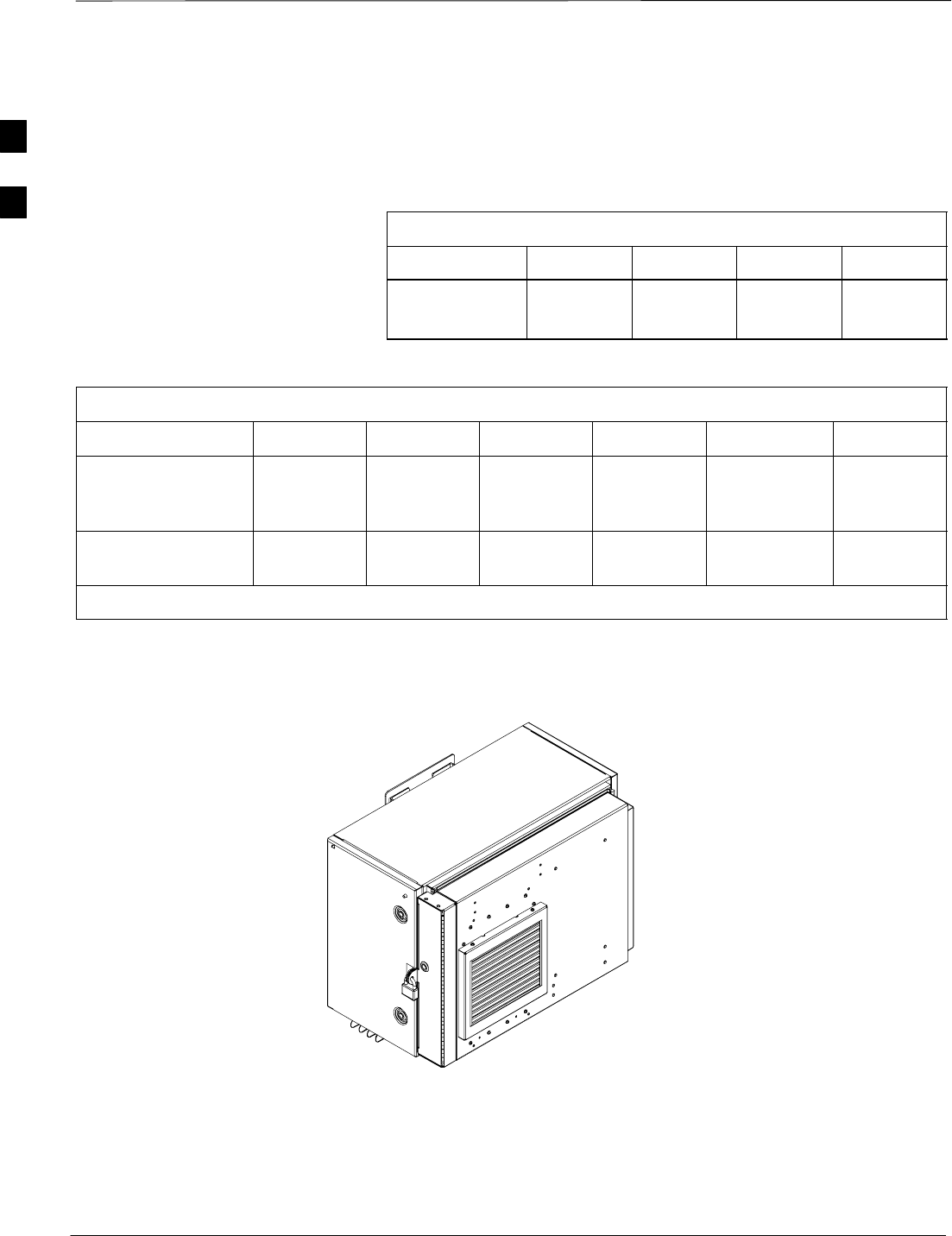
Dimensions and Clearances – continued
DRAFT
1X SC480 BTS Hardware Installation, Optimization/ATP, and FRU Jun 2004
2-20
TME Dimensions and
Clearances
Table 2-10, Table 2-11, Figure 2-9, and Figure 2-10 show the TME
installed dimensions and recommended clearances.
Table 2-10: Installation Dimensions for the TME
Item Height Length Width Weight
TME 530 mm
(21 in.)
738 mm
(29 in.)
448 mm
(18 in.)
34 kg
(75 lbs)
Table 2-11: Minimum Clearances for the TME
Item Front Back Left Right Top Bottom
Installation and
Maintenance
Requirements
705 mm
(30 in.) 51 mm
(2 in.) 600 mm
(24 in. 600 mm
(24 in.) 80 mm
(3 in.) *1000 mm
(39 in.)
Functional
Requirements 100 mm
(30 in.) 51 mm
(2 in.) 300 mm
(12 in.) 300 mm
(12 in.) 80 mm
(3 in.) *1000 mm
(39 in.)
* Minimum of 1 Meter for ground clearance.
Figure 2-8: TME
ti–cdma–wp–00357–v01–ildoc–ah
2
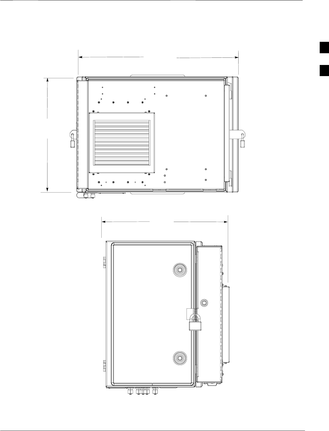
Dimensions and Clearances – continued
Jun 2004 2-21
1X SC480 BTS Hardware Installation, Optimization/ATP, and FRU
DRAFT
738 mm
448 mm
530 mm
Figure 2-9: Overall Dimensions of the Thermal Management Enclosure
ti–cdma–wp–00354–v01–ildoc–ah
ti–cdma–wp–00353–v01–ildoc–ah
2

Dimensions and Clearances – continued
DRAFT
1X SC480 BTS Hardware Installation, Optimization/ATP, and FRU Jun 2004
2-22
TME Clearances
Figure 2-10 shows the recommended clearances for the TME.
Figure 2-10: Functional Clearances for TME
Side Clearance
300 mm
Front Clearance
100 mm
Rear Clearance
51 mm
Top Clearance
80 mm
Bottom Clearance
1 M
Side Clearance
300 mm
2
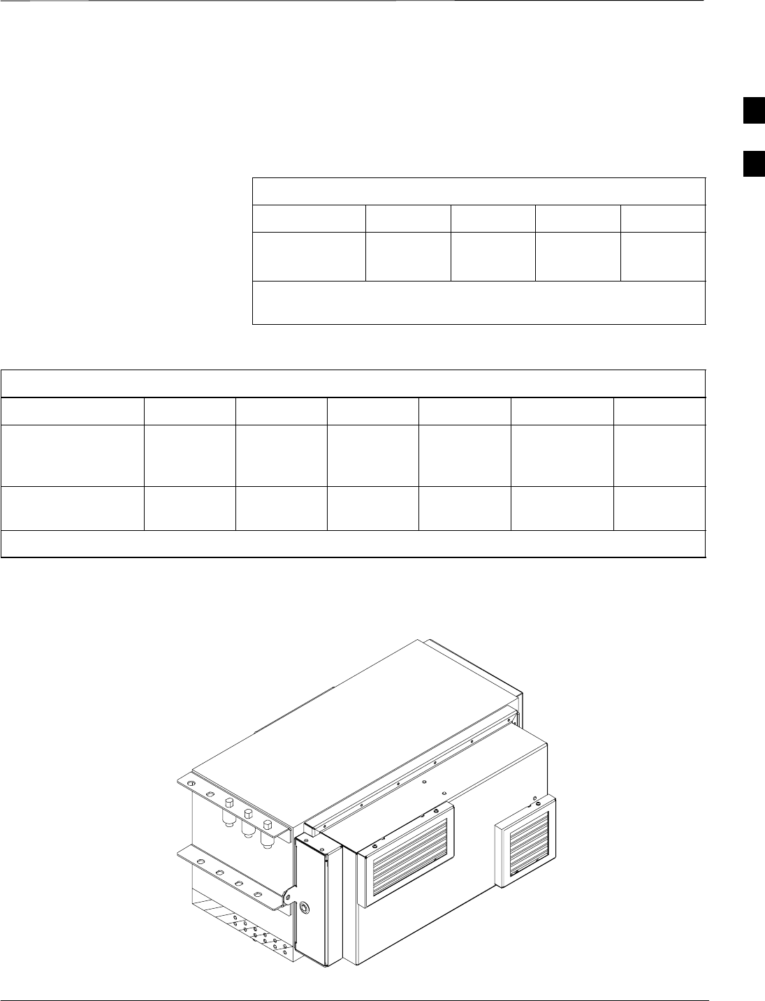
Dimensions and Clearances – continued
Jun 2004 2-23
1X SC480 BTS Hardware Installation, Optimization/ATP, and FRU
DRAFT
PDE Dimensions and
Clearances
Table 2-12, Table 2-13, and Figure 2-11 and Figure 2-12 show the
installed dimensions and recommended clearances for each item.
Table 2-12: Installation Dimensions for the PDE
Item Height Length Width Weight
PDE *350 mm
(14 in.)
810 mm
(32 in.)
473 mm
(19 in.)
52 kg
(115 lbs)
* Mounting Bracket extends an additional 186 mm (7 in) beyond
bottom of TME.
Table 2-13: Minimum Clearances for the PDE
Item Front Back Left Right Top Bottom
Installation and
Maintenance
Requirements
760 mm
(30 in.) 51 mm
(2 in.) 334 mm
(13 in.) 334 mm
(13 in.) 150 mm
(6 in.) *150 mm
(6 in.)
Functional
Requirements 300 mm
(12 in.) 51 mm
(2 in.) 150 mm
(6 in.) 150 mm
(6 in.) 150 mm
(6 in.) *150 mm
(6 in.)
* Minimum of 1 Meter for ground clearance.
Figure 2-11: PDE
ti–cdma–wp–00336–v01–ildoc–ah
2
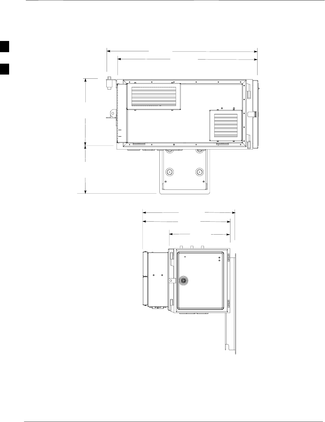
Dimensions and Clearances – continued
DRAFT
1X SC480 BTS Hardware Installation, Optimization/ATP, and FRU Jun 2004
2-24
Figure 2-12: PDE Overall Dimensions
186 mm
350 mm
760 mm
810 mm
473 mm
305mm
444 mm
ti–cdma–wp–00270–v01–ildoc–ah
2
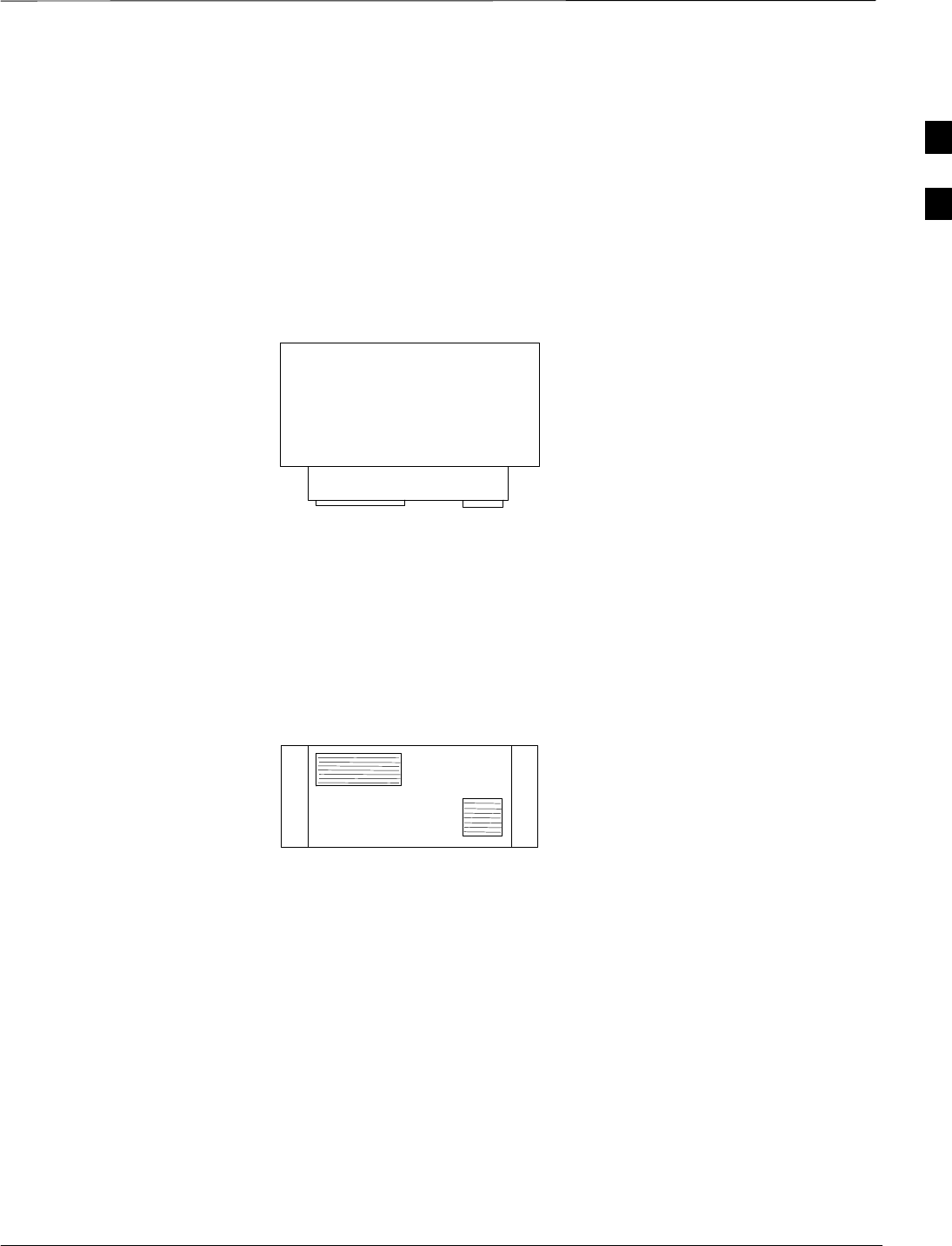
Dimensions and Clearances – continued
Jun 2004 2-25
1X SC480 BTS Hardware Installation, Optimization/ATP, and FRU
DRAFT
PDE Clearances
Figure 2-13 shows the recommended clearances for the PDE.
Figure 2-13: Functional Clearances for PDE
Side Clearance
150 mm
Front Clearance
300 mm
Rear Clearance
51 mm
Top Clearance
150 mm
Bottom Clearance
1 M
Side Clearance
150 mm
Outdoor Clearances
Figure 2-14 and Figure 2-15 show the minimum clearances for the
outdoor configuration.
2
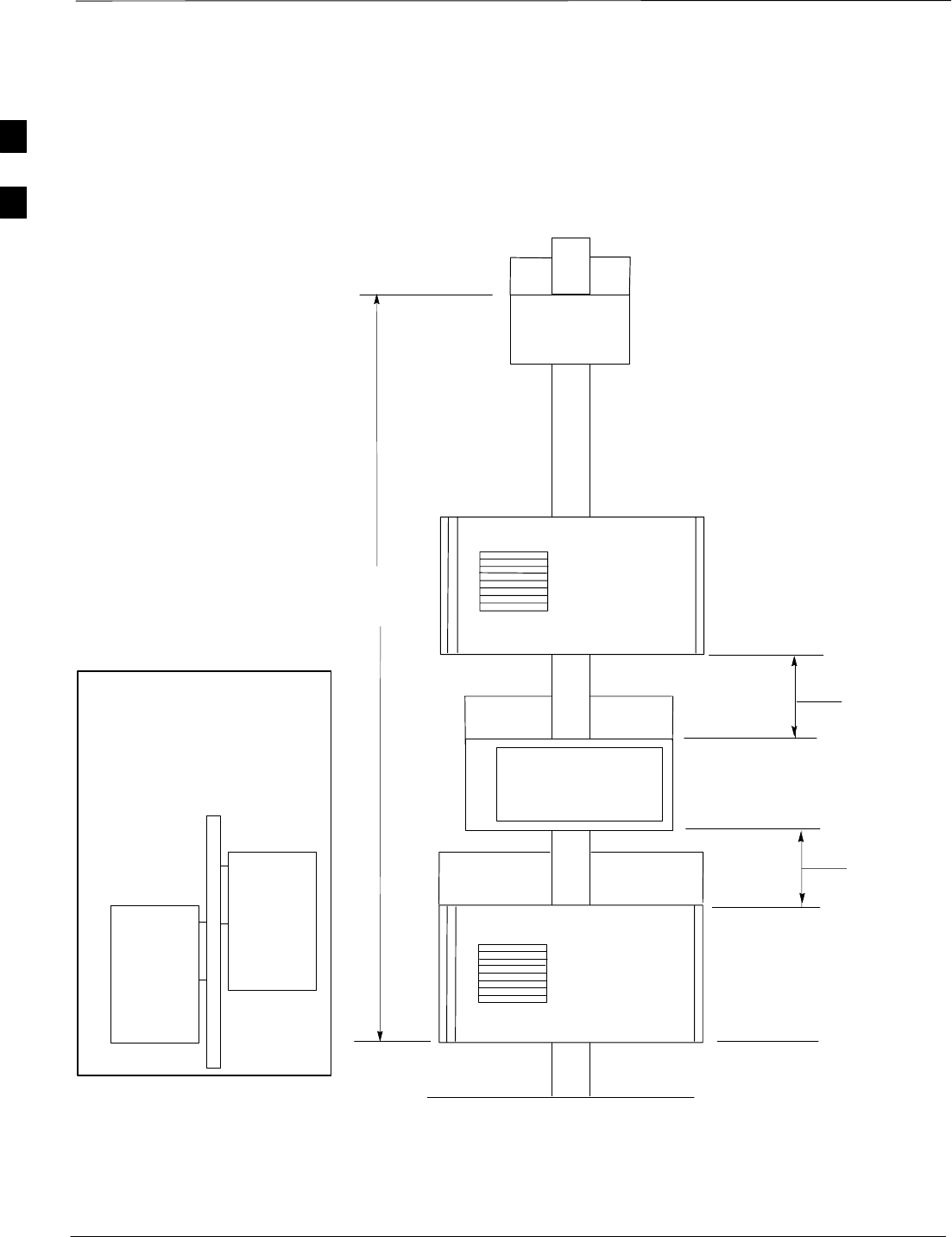
Dimensions and Clearances – continued
DRAFT
1X SC480 BTS Hardware Installation, Optimization/ATP, and FRU Jun 2004
2-26
Figure 2-14: Mulitple Pole Installation and Functional Clearances for Enclosures and PA
BTS with TME/HMS, PDE HX, & PA
Front View
PA 1
TME 3
1000 mm
Minimum
TME 1
PDE 1
1000 mm
Minimum
10 Meters
1000 mm
Minimum
Electrical connections
not shown
TME 2&4, PDE 2, and
PA2 are attached on
the opposite side of the
pole.
Ground Level
PDE 2
TME 2
PA 2
Partial
Side View
2
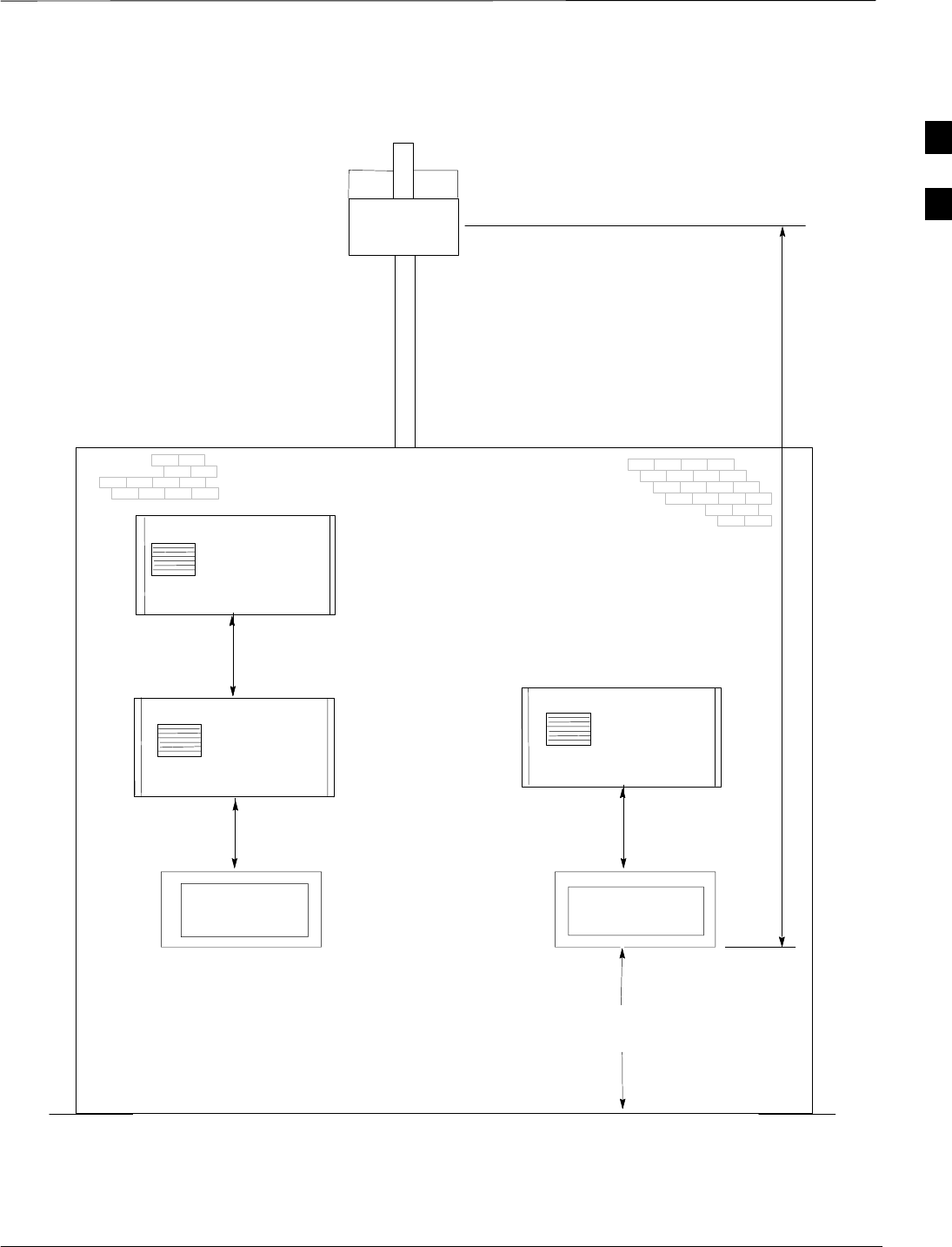
Dimensions and Clearances – continued
Jun 2004 2-27
1X SC480 BTS Hardware Installation, Optimization/ATP, and FRU
DRAFT
Figure 2-15: Multiple Wall Installation and Functional Clearances for TME and HMS, PDE, and
cCLPA
1000 mm
Minimum
TME #1 TME #3
TME #2
PDE #2PDE #1
PA #1
Battery Backup not
shown. Batteries are
connected through
the PDE.
Electrical connections
not shown
1000 mm
minimum
1000 mm
Minimum
1000 mm
Minimum
Ground Level
A possible layout is
shown.
10 Meters
Wall
PA #2
Front View
2

Dimensions and Clearances – continued
DRAFT
1X SC480 BTS Hardware Installation, Optimization/ATP, and FRU Jun 2004
2-28
Notes
2

Jun 2004 1X SC480 BTS Hardware Installation, Optimization/ATP, and FRU
DRAFT
Chapter 3: BTS Cables
Table of Contents
Cable Description 3-1 . . . . . . . . . . . . . . . . . . . . . . . . . . . . . . . . . . . . . . . . . . . . . . . .
Overview 3-1 . . . . . . . . . . . . . . . . . . . . . . . . . . . . . . . . . . . . . . . . . . . . . . . .
Configurations Supported 3-1 . . . . . . . . . . . . . . . . . . . . . . . . . . . . . . . . . . .
Cabling Installation Order 3-1 . . . . . . . . . . . . . . . . . . . . . . . . . . . . . . . . . . .
Cable Labels 3-1 . . . . . . . . . . . . . . . . . . . . . . . . . . . . . . . . . . . . . . . . . . . . .
Ground Lug Specification 3-1 . . . . . . . . . . . . . . . . . . . . . . . . . . . . . . . . . . .
Customer I/O Connector 3-2 . . . . . . . . . . . . . . . . . . . . . . . . . . . . . . . . . . . .
Cable Descriptions and Part Numbers 3-2 . . . . . . . . . . . . . . . . . . . . . . . . . .
Cabling for EV–DO 3-3 . . . . . . . . . . . . . . . . . . . . . . . . . . . . . . . . . . . . . . . .
Power, Earth Ground, and Battery Cabling 3-4 . . . . . . . . . . . . . . . . . . . . . . . . . . . .
Objective 3-4 . . . . . . . . . . . . . . . . . . . . . . . . . . . . . . . . . . . . . . . . . . . . . . . .
Grounding Considerations 3-4 . . . . . . . . . . . . . . . . . . . . . . . . . . . . . . . . . . .
Indoor Power Considerations 3-5 . . . . . . . . . . . . . . . . . . . . . . . . . . . . . . . .
Outdoor Power Considerations 3-5 . . . . . . . . . . . . . . . . . . . . . . . . . . . . . . .
Antenna Cabling 3-6 . . . . . . . . . . . . . . . . . . . . . . . . . . . . . . . . . . . . . . . . . . . . . . . . .
Cable Labels 3-6 . . . . . . . . . . . . . . . . . . . . . . . . . . . . . . . . . . . . . . . . . . . . .
Required Cables 3-6 . . . . . . . . . . . . . . . . . . . . . . . . . . . . . . . . . . . . . . . . . . .
Antenna Cable Pin and Signal Information 3-6 . . . . . . . . . . . . . . . . . . . . . .
Span Line Cabling 3-7 . . . . . . . . . . . . . . . . . . . . . . . . . . . . . . . . . . . . . . . . . . . . . . .
Cable Labels 3-7 . . . . . . . . . . . . . . . . . . . . . . . . . . . . . . . . . . . . . . . . . . . . .
Required Tools and Materials 3-7 . . . . . . . . . . . . . . . . . . . . . . . . . . . . . . . .
Cable Pin and Signal Information for Span Cabling 3-7 . . . . . . . . . . . . . . .
Remote GPS Head and Cabling 3-8 . . . . . . . . . . . . . . . . . . . . . . . . . . . . . . . . . . . . .
Objective 3-8 . . . . . . . . . . . . . . . . . . . . . . . . . . . . . . . . . . . . . . . . . . . . . . . .
Cable Labels 3-8 . . . . . . . . . . . . . . . . . . . . . . . . . . . . . . . . . . . . . . . . . . . . .
Required Tools and Materials 3-8 . . . . . . . . . . . . . . . . . . . . . . . . . . . . . . . .
Cable Pin and Signal Information for RGPS Cabling 3-8 . . . . . . . . . . . . .
RGPS Mounting Considerations 3-9 . . . . . . . . . . . . . . . . . . . . . . . . . . . . . .
Local GPS (RF–GPS) Antenna Cabling 3-11 . . . . . . . . . . . . . . . . . . . . . . . . . . . . . . .
Objective 3-11 . . . . . . . . . . . . . . . . . . . . . . . . . . . . . . . . . . . . . . . . . . . . . . . .
Cable labels 3-11 . . . . . . . . . . . . . . . . . . . . . . . . . . . . . . . . . . . . . . . . . . . . . .
Cabling diagram 3-11 . . . . . . . . . . . . . . . . . . . . . . . . . . . . . . . . . . . . . . . . . . .
Equipment needed 3-11 . . . . . . . . . . . . . . . . . . . . . . . . . . . . . . . . . . . . . . . . .
Mounting Considerations 3-12 . . . . . . . . . . . . . . . . . . . . . . . . . . . . . . . . . . .
3

Table of Contents – continued
1X SC480 BTS Hardware Installation, Optimization/ATP, and FRU Jun 2004
DRAFT
Notes
3

Cable Description
Jun 2004 1X SC480 BTS Hardware Installation, Optimization/ATP, and FRU 3-1
DRAFT
Overview
This chapter provides the procedures to install the BTS site cabling, but
not attach it to the BTS .
Connect the cables to the site and route them to the BTS location.
Procedures for attaching the cables to the BTS is contained in Chapter 4.
Cabling is one of the most noticeable aspects of
workmanship. Straight runs and proper turns are critical for
a positive evaluation of the work.
NOTE
Configurations Supported
This chapter supports cable installation for single carrier omni
configurations.
Cabling Installation Order
To install the cables, Motorola recommends that the following
procedures be completed in the order shown:
1. Earth ground cabling
2. Power cabling
3. Antenna cabling
4. Span cabling
5. cCLPA Data cable
6. RGPS/Local GPS/HSO/MSO cabling (HSO/MSO optional)
7. Customer I/O cabling
8. EV–DO (MCC–DO) Cabling
Cable Labels
The “Cable Descriptions and Part Numbers” in Table 3-1 provides cable
descriptions and part numbers. The labels used to designate the cables in
that area are used throughout this chapter.
Ground Lug Specification
Ground lugs with the following specification is recommended for use
with the system.
SILSCO P/N: CRB–6L2–14–58 – Two Hole, Long Barrel lug
connector, 6 AWG, 1/4–inch diameter, 5/8–inch stud hole spacing,
13/32 Tang width
3

Cable Description – continued
3-2 1X SC480 BTS Hardware Installation, Optimization/ATP, and FRU Jun 2004
DRAFT
Customer I/O Connector
The recommended connector for Customer Input and Output is listed
below:
SInput Connector: Molex, terminla plugs, P/N 39352–0106
SOutput Connector: Molex, terminla plugs, P/N 39352–0108
Cable Descriptions and Part
Numbers
Table 3-1 gives the cable descriptions and part numbers for the cables
used to install the BTS.
Table 3-1: Cable Descriptions and Part Numbers
Cable Qty. Part Number Description
A 2 Customer
Supplied Ground cable, 6 -AWG, insulated copper wire. Requires one two–hole
lug connectors.
B 1–6 Andrew
LDF4–50
Customer
Supplied
Antenna Cable, 800 MHz, length selections: 10 m (31 ft.)
C 1 T472AA RGPS cable, 15 m (50 ft.)
T472AB RGPS cable, 38 m (125 ft.)
T472AC RGPS cable, 76 m (250 ft.)
T472AD RGPS cable, 152 m (500 ft.)
T472AE RGPS cable, 304 m (1000 ft.)
T472AF RGPS cable, 608 m (2000 ft.)
C1 1 T650AA Punchblock to CBIO Board, 15 pin D–connector on one end and loose
wires on the other end.
D 1 Customer
Supplied Span cable, 4 or 8 conductors, 24–28 AWG stranded, twisted pair
E 1 Customer
Supplied Customer Input/Output cable, 0–8 conductors, 18–24 AWG stranded
wire
F 2 Customer
Supplied DC power cable with crimped lugs, 8–10 AWG, 10 m, stranded,
designed for –60 to –40 or +20 to +35 VDC power input
G 1 Customer
Supplied RJ45 cable for BTS to cCLPA
H 1–11 3086039H18 RGPS Synchronization cable (part of kit SGKN4351A)
3086039H19 RGPS Synchronization cable (part of kit SGKN4352A)
J** 1 Supplied in Kit
SGRG4030 Local GPS Cable, 1/2–inch coaxial, length = 50 ft. Two male N–type
connectors, one end to be terminated after routing of cable
table continued on next page
3

Cable Description – continued
Jun 2004 1X SC480 BTS Hardware Installation, Optimization/ATP, and FRU 3-3
DRAFT
Table 3-1: Cable Descriptions and Part Numbers
Cable DescriptionPart NumberQty.
K 1 Customer
Supplied AC power cable, 10 AWG, copper, designed for 200 – 240 VAC @ 25
A.
L{2–7 Customer
Supplied DC power cables, 8–10 AWG, stranded, designed for +20 to +34 VDC
power input
*Quantity of cables depends upon system configuration. Your system may require one or more Motorola kits.
Refer to Motorola Kits for Multi–Unit Installations for more information
** An SMA to N adapter is required; otherwise, a cable must be made with an SMA connector on one end
{ Length of cables are dependent upon BTS equipment layout.
Cabling for EV–DO
Information regarding EV–DO (MCC–DO) cabling can be found in
1xEV–DO Hardware Installation manual – 68P09257A95
3
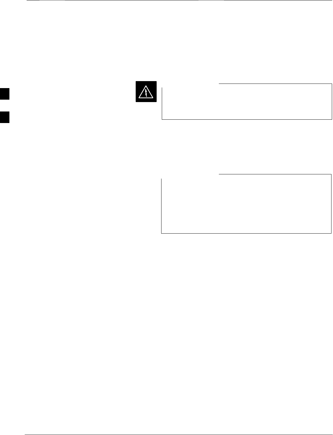
Power, Earth Ground, and Battery Cabling
DRAFT
1X SC480 BTS Hardware Installation, Optimization/ATP, and FRU Jun 2004
3-4
Objective
The objective of this procedure is to install the power and earth ground
cabling for the BTS at the site.
Dangerous voltages, capable of causing death, are present
in this equipment. Use extreme caution when handling and
testing this equipment.
WARNING
Grounding Considerations
This procedure covers only the grounding information for the cable that
attaches to the BTS.
Motorola recommends that you use an oxide inhibitor such
as Burndy PENETROXt or Ilsco DE–OXt on all the
external ground connections on the unit and on the site I/O
interface for all outdoor installations. This includes the
ground connections on the mounting bracket, the Site I/O,
and the lugs on the customer–supplied site I/O interface.
NOTE
Above Ground
For ground rings and the interconnection of internal and external ground
rings, #2 AWG or larger is required. For grounding of equipment and
miscellaneous metallic objects, #6 AWG miminum is required.
Exceptions – Connection from an isolated ground bar (IGB) to master
ground bar (MGB) is accomplished using #2 AWG as a minimum. The
external ground bar (EGB) is grounded through a 2–inch wide, 16–gauge
copper strap, if available; otherwise, 2–#2 AWG wires can be used. If the
#2AWG wires are used, then they must be connected at opposite ends of
the EGB and have a minimum separation of 12–inches between them.
Below Ground
All wire must be #2 AWG as a minimum. Ground rods are to be a
minimum of 8 feet long and 5/8–inch in diameter. In the case of a deep
basement next to the rod, the rod must be long enough to extend 3 feet
below the basement floor.
3

Power, Earth Ground, and Battery Cabling – continued
Jun 2004 3-5
1X SC480 BTS Hardware Installation, Optimization/ATP, and FRU
DRAFT
Indoor Power Considerations
The BTS is designed for +20 to +34 VDC power input.
The power for the Indoor BTS configuration is:
SDC power
Outdoor Power
Considerations
The TME/BTS and cCLPA are designed for +20 to +34 VDC power
input from the PDE.
The PDE is designed for 200–240 VAC input.
The power for the Outdoor BTS configuration is:
SAC power
SDC power (converted from AC)
SDC power (Battery Backup if used)
Neither the “+” or “–” terminal of the DC Input is
connected to the BTS ground. If a negative supply input is
provided, the “+” terminal of the DC input must be
connected to the Master Ground Bar. By connecting the
“+” terminal of the DC input to the MGB, a +27 VDC
(nominal) system is created.
NOTE
The system configuration determines which power cables are installed.
The ground cable is always installed first. Based on the system
configuration perform the appropriate procedures described in Chapter 4.
3
Antenna Cabling
DRAFT
1X SC480 BTS Hardware Installation, Optimization/ATP, and FRU Jun 2004
3-6
Cable Labels
The cable designations are referenced to Table 3-1 in the “Cable
Description” area of this chapter.
Required Cables
Table 3-2 provides the quantities and descriptions of the cables.
Table 3-2: Cables Needed for Antenna Connections
Cable Qty. Part Number Description
B1 to 4* Andrew
LDF4–50
Customer Supplied
Antenna Cable, 800 MHz, 10 m (31 ft.)
* Four cables are required if a cCLPA is used, otherwise, two are needed for the BTS only.
Antenna Cable Pin and Signal
Information
The antenna cabling uses a 50–Ohm coaxial cable. The inner conductor
provides signaling and the outer conductor provides shielding and
ground.
Figure 3-1: Antenna Cabling Details
OUTER
CONDUCTOR
INNER
CONDUCTOR
ANTENNA CABLE (COAXIAL)
CONNECTOR
Table 3-3: Pin and Signal Information for Cable B (Antenna Cable)
Antenna Inner Conductor Outer
Conductor
B TX/RX Ground
A RX Ground
3
Span Line Cabling
Jun 2004 3-7
1X SC480 BTS Hardware Installation, Optimization/ATP, and FRU
DRAFT
Cable Labels
The cable designations are referenced to Table 3-1 in the “Cable
Description” area of this chapter.
Required Tools and Materials
Table 3-4 provides the quantities and descriptions of the cables.
Table 3-4: Cables Needed for Span/RGPS Connections
Cable Qty. Part Number Description
D 1–3 Customer Supplied Span cable, 4 or 8 conductors, 24–28 AWG stranded, twisted pair
1 –4* 7687717T02 Ferrite, clip–on core
* One Ferrite bead per cable.
Cable Pin and Signal
Information for Span Cabling
Table 3-5 gives the pin and signal information for the Span cable.
Table 3-5: Pin/Signal Information for Span Cable
BTS Interface Pin Wire/Stripe
Color Description
1 White/Orange RX RING
2 Orange RX TIP
3 White/Green NC
Span Line Cable
4 Blue TX RING
Span Line Cable
5 White/Blue TX TIP
6 Green NC
7 White/Brown NC
8 Brown NC
3

Remote GPS Head and Cabling
DRAFT
1X SC480 BTS Hardware Installation, Optimization/ATP, and FRU Jun 2004
3-8
Objective
This section contains general information on the Remote Global
Positioning System (RGPS) cabling and RGPS head. For installation
information refer to Chapter 4, beginning with Table 4-36.
Cable Labels
The cable designations are referenced to Table 3-1 in the “Cable
Description” area of this chapter.
Required Tools and Materials
One RGPS Head (Motorola Part Number 0186012H03 or 0186012H04)
is required.
Table 3-6: Cables Needed for Span/RGPS Connections
Cable Qty. Part Number Description
C 1 T472AA RGPS cable, 15 m (50 ft.)
T472AB RGPS cable, 38 m (125 ft.)
T472AC RGPS cable, 76 m (250 ft.)
T472AD RGPS cable, 152 m (500 ft.)
T472AE RGPS cable, 304 m (1000 ft.)
T472AF RGPS cable, 608 m (2000 ft.)
C1 1 T650AA Punchblock to CBIO Board, 15 pin D–connector on one end and
loose wires on the other end.
1 –4* 7687717T02 Ferrite, clip–on core
* One Ferrite bead per cable.
Cable Pin and Signal
Information for RGPS Cabling
Table 3-7 gives the pin and signal information for the RGPS cable.
Connector must be a 15 pin, D–Sub, female.
Table 3-7: RGPS Pin/Signal Name Information
Pin Signal Name
1DATA + (From Head)
2SYNC + (From Head)
3SYNC + (Not used for RGPS connection, daisy
chain use between BTSs only)
4DATA + (To Head)
5 NC
3

Remote GPS Head and Cabling – continued
Jun 2004 3-9
1X SC480 BTS Hardware Installation, Optimization/ATP, and FRU
DRAFT
Table 3-7: RGPS Pin/Signal Name Information
Pin Signal Name
6 NC
7RGPS +28V Supply
8RGPS +28V Supply
9DATA – (From Head)
10 SYNC – (From Head)
11 SYNC – (To Head)
12 DATA – (To Head)
13 NC
14 RGPS Return
15 RGPS Return
RGPS Mounting
Considerations
The RGPS Head requires specific mounting considerations in order to
properly observe the GPS satellites.
SThe mounting pipe for the RGPS head should be mounted vertically
with less than five degrees (5_) of tilt.
SThe RGPS head mounting hardware which comes with the RGPS
head should be used in all installations. This mounting hardware
properly isolates the painted metal base of the RGPS head from other
conductive surfaces. If the metal base comes in contact with another
conductive surface, the electrical surge resistance of the RGPS head
can be significantly reduced leading to RGPS head failure.
– If the supplier of the RGPS mounting hardware cannot be used, the
installer MUST make certain that the metal base of the RGPS head
does not make contact with any conductive surface.
SPosition the RGPS head to have an unobstructed view of the sky and
to minimize the chance of debris (leaves, dirt, etc.) accumulating on
the radome of the RGPS head.
SThe RGPS head must have a clear view of the sky, preferably to
within ten degrees (10_) of the horizon in all directions. The total
blockage of the sky (due to buildings, mountains, etc.) should be less
than 50%.
SPlace the RGPS head as far away from the BTS transmit antenna as
possible to avoid RF interference issues.
3

Remote GPS Head and Cabling – continued
DRAFT
1X SC480 BTS Hardware Installation, Optimization/ATP, and FRU Jun 2004
3-10
SPlace the RGPS head at least 15 m away from lightning rods, towers,
or structures that attract lightning. RGPS head damage is usually not
the result of a direct lightning strike, but of a lightning strike on a
nearby structure. Also, since a lightning rod is connected to an earth
ground, it can act as a shield and create a shadow that may block or
reduce the signal from a satellite.
SAfter the BTS is powered up, check the RGPS signal strengths with
the “gstatus” command on the CSA MMI port.
– An optimal installation will have at least one satellite (SV) with an
RSSI value ≥ 50, and at least four (4) satellites with RSSI values
≥ 45.
– A minimal installation should have at least four (4) satellites with
RSSI values ≥ 40.
SThe RGPS head is rated for ambient air temperatures from –40°C
(–40°F) to 80°C (176°F), and has ratings for humidity, shock,
waterproof, UV light resistance, vibrations, salt fog, ESD, EMI, and
altitude.
SThe RGPS system used for the SCt480 BTS will support up to 604
m (2000 ft.) of overall cable length from the RGPS head to the last
connected BTS. If a long cable run needs to be broken into pieces,
minimize the number of breaks in the cable.
SA Compact BTS equipped with an SDCX is capable of providing up
to three other BTSs with timing signals.
3

Local GPS (RF–GPS) Antenna Cabling
Jun 2004 1X SC480 BTS Hardware Installation, Optimization/ATP, and FRU
DRAFT
3-11
Objective
This section contains general information on the Radio Frequency
Global Positioning System receiver (RF–GPS) antenna cabling. More
commonly referred to as Local GPS. Refer to Table 4-37 for installation
information.
Cable labels
The cable designations referenced to Table 3-1 in the “Overall Cabling
and Descriptions” area.
Cabling diagram
Figure 4-48 shows the Local GPS antenna connections.
Equipment needed
Table 3-8 contains a detailed description of the Local GPS Cabling.
Table 1-3 lists the tools needed.
Table 3-8: Cabling for Local GPS
Cable Qty. Part Number Description
J* 1 Receiver
SGRG4030
RF–GPS Cable, 1/2–inch coaxial, length = 50 ft. Two male N–type
connectors, one end loose.
If lengths greater than 50 ft. are required, cable style and length should
be determined by site configurations. Maximum loss <4.5 dB @ 1575
MHz for all cabling and connections between the Local GPS antenna
and the frame.
1 CGDSGPSKITF
4NM50 Assembly, Receiver, RF–GPS with 50 ft cable
*An SMA to N adapter is required; otherwise, a smaller diameter cable must be made with an SMA connector
on one end, with a maximum loss of <4.5 dB.
3

Local GPS (RF–GPS) Antenna Cabling – continued
DRAFT
1X SC480 BTS Hardware Installation, Optimization/ATP, and FRU Jun 2004
3-12
Mounting Considerations
Table 3-9 lists the Local GPS Head requires specific mounting
considerations in order to properly observe the GPS satellites.
Table 3-9: Local GPS Antenna Mounting Considerations
nConsideration
1The mounting pipe for the Local GPS Head should be mounted vertically with less than five (5)
degrees of tilt.
2The Local GPS Head requires a clear view of the sky, preferably to within ten (10) degrees of the
horizon in all directions. The more sky that is observed increases the number of potential satellites
that can be tracked, resulting in better Local GPS performance.
3During normal operation, the Local GPS Head continuously tracks a minimum of four (4) GPS
satellites. However, it is theoretically possible to operate the BTS by tracking only one (1) GPS
satellite. Motorola does not recommend tracking only one (1) GPS satellite unless there has been
an accurate site survey.
4Place the Local GPS Head where RF obstructions of the sky are minimal. The “sky” includes
everything to within ten (10) degrees of the horizon in all directions. RF obstructions include
buildings, towers, natural rock formations, snow, foliage, and debris.
5Separate the Local GPS Head from other radiating sources. Excessive RF energy can degrade the
Local GPS Head’s ability to observe the GPS satellites. The Local GPS Head receives on the GPS
L1 frequency of 1575.42 MHz and incorporates filters to minimize the effects of potential RF
interference, however, strong radiants can overwhelm the filters, thus degrading the units reception
capability.
6The Local GPS Head is rated for ambient air temperatures in the range –40 to + 50_C, and has
ratings for humidity, shock, waterproofing, UV light resistance, vibrations, salt, fog, ESD, EMI,
and altitude.
7If the overall length of the Local GPS Head to the BTS is greater than 50 feet, the cable style and
length should be determined by the site configurations. The maximum loss should be less than
4.5 dBm @ 1575 MHz for all cabling and connections between the Local GPS Head and the
frame.
3

Jun 2004 1X SC480 BTS Hardware Installation, Optimization/ATP, and FRU
DRAFT
Chapter 4: BTS and Cabling Installation
Table of Contents
Installation Overview 4-1 . . . . . . . . . . . . . . . . . . . . . . . . . . . . . . . . . . . . . . . . . . . . .
Overview 4-1 . . . . . . . . . . . . . . . . . . . . . . . . . . . . . . . . . . . . . . . . . . . . . . . .
Procedure order 4-1 . . . . . . . . . . . . . . . . . . . . . . . . . . . . . . . . . . . . . . . . . . .
Installation of EV–DO 4-2 . . . . . . . . . . . . . . . . . . . . . . . . . . . . . . . . . . . . . .
Connector Locations 4-3 . . . . . . . . . . . . . . . . . . . . . . . . . . . . . . . . . . . . . . . . . . . . . .
Connector Locations 4-3 . . . . . . . . . . . . . . . . . . . . . . . . . . . . . . . . . . . . . . .
Indoor/Outdoor Configuration Connectors 4-4 . . . . . . . . . . . . . . . . . . . . . .
Outdoor Configuration Connectors 4-4 . . . . . . . . . . . . . . . . . . . . . . . . . . . .
Attaching BTS to Mounting Rack 4-5 . . . . . . . . . . . . . . . . . . . . . . . . . . . . . . . . . . .
Objective 4-5 . . . . . . . . . . . . . . . . . . . . . . . . . . . . . . . . . . . . . . . . . . . . . . . .
Background 4-5 . . . . . . . . . . . . . . . . . . . . . . . . . . . . . . . . . . . . . . . . . . . . . .
Required Tools and Materials 4-5 . . . . . . . . . . . . . . . . . . . . . . . . . . . . . . . .
Procedure to Attach Mounting Plate to Rack 4-6 . . . . . . . . . . . . . . . . . . . .
BTS Mounting Bracket 4-7 . . . . . . . . . . . . . . . . . . . . . . . . . . . . . . . . . . . . .
BTS to Mounting Plate 4-8 . . . . . . . . . . . . . . . . . . . . . . . . . . . . . . . . . . . . .
Compact Combined Linear Power Amplifier Installation 4-10 . . . . . . . . . . . . . . . . .
Objective 4-10 . . . . . . . . . . . . . . . . . . . . . . . . . . . . . . . . . . . . . . . . . . . . . . . .
Cable Description 4-10 . . . . . . . . . . . . . . . . . . . . . . . . . . . . . . . . . . . . . . . . .
Required Tools 4-10 . . . . . . . . . . . . . . . . . . . . . . . . . . . . . . . . . . . . . . . . . . . .
Indoor cCLPA Installation 4-10 . . . . . . . . . . . . . . . . . . . . . . . . . . . . . . . . . . .
cCLPA Connectors 4-11 . . . . . . . . . . . . . . . . . . . . . . . . . . . . . . . . . . . . . . . .
cCLPA Mounting Procedure 4-11 . . . . . . . . . . . . . . . . . . . . . . . . . . . . . . . . .
cCLPA Grounding 4-12 . . . . . . . . . . . . . . . . . . . . . . . . . . . . . . . . . . . . . . . . .
DC Power Connection Procedure 4-14 . . . . . . . . . . . . . . . . . . . . . . . . . . . . .
Data Cable Description and Part Number 4-15 . . . . . . . . . . . . . . . . . . . . . . .
Data Cable Wiring Information 4-16 . . . . . . . . . . . . . . . . . . . . . . . . . . . . . . .
BTS Data Cable Connection Procedure 4-17 . . . . . . . . . . . . . . . . . . . . . . . .
Outdoor cCLPA Installation 4-19 . . . . . . . . . . . . . . . . . . . . . . . . . . . . . . . . .
Pole or Wall Mounting cCLPA 4-19 . . . . . . . . . . . . . . . . . . . . . . . . . . . . . . .
Thermal Management Enclosure Installation 4-21 . . . . . . . . . . . . . . . . . . . . . . . . . . .
Objective 4-21 . . . . . . . . . . . . . . . . . . . . . . . . . . . . . . . . . . . . . . . . . . . . . . . .
Electrical Requirements 4-21 . . . . . . . . . . . . . . . . . . . . . . . . . . . . . . . . . . . . .
Environmental Requirements 4-22 . . . . . . . . . . . . . . . . . . . . . . . . . . . . . . . .
Weight Requirement 4-22 . . . . . . . . . . . . . . . . . . . . . . . . . . . . . . . . . . . . . . .
TME Connectors and Conduit Locations 4-22 . . . . . . . . . . . . . . . . . . . . . . .
TME Conduit Sizes 4-23 . . . . . . . . . . . . . . . . . . . . . . . . . . . . . . . . . . . . . . . .
4

Table of Contents – continued
1X SC480 BTS Hardware Installation, Optimization/ATP, and FRU Jun 2004
DRAFT
Materials 4-23 . . . . . . . . . . . . . . . . . . . . . . . . . . . . . . . . . . . . . . . . . . . . . . . .
TME Installation 4-23 . . . . . . . . . . . . . . . . . . . . . . . . . . . . . . . . . . . . . . . . . .
Compact BTS and HMS Installation 4-28 . . . . . . . . . . . . . . . . . . . . . . . . . . . . . . . . .
Objective 4-28 . . . . . . . . . . . . . . . . . . . . . . . . . . . . . . . . . . . . . . . . . . . . . . . .
Compact BTS Installation 4-28 . . . . . . . . . . . . . . . . . . . . . . . . . . . . . . . . . . .
HMS Installation 4-30 . . . . . . . . . . . . . . . . . . . . . . . . . . . . . . . . . . . . . . . . . .
Power Distribution Enclosure Installation 4-32 . . . . . . . . . . . . . . . . . . . . . . . . . . . . .
Objective 4-32 . . . . . . . . . . . . . . . . . . . . . . . . . . . . . . . . . . . . . . . . . . . . . . . .
Electrical 4-33 . . . . . . . . . . . . . . . . . . . . . . . . . . . . . . . . . . . . . . . . . . . . . . . .
Environmental 4-33 . . . . . . . . . . . . . . . . . . . . . . . . . . . . . . . . . . . . . . . . . . . .
Weight 4-33 . . . . . . . . . . . . . . . . . . . . . . . . . . . . . . . . . . . . . . . . . . . . . . . . . .
PDE Conduit Sizes 4-34 . . . . . . . . . . . . . . . . . . . . . . . . . . . . . . . . . . . . . . . .
Materials 4-36 . . . . . . . . . . . . . . . . . . . . . . . . . . . . . . . . . . . . . . . . . . . . . . . .
PDE Installation 4-36 . . . . . . . . . . . . . . . . . . . . . . . . . . . . . . . . . . . . . . . . . . .
Mounting Bracket Assembly Procedure 4-37 . . . . . . . . . . . . . . . . . . . . . . . .
Heat Exchanger 4-40 . . . . . . . . . . . . . . . . . . . . . . . . . . . . . . . . . . . . . . . . . . .
Heat Exchanger Details 4-41 . . . . . . . . . . . . . . . . . . . . . . . . . . . . . . . . . . . . .
Heat Exchanger Installation 4-41 . . . . . . . . . . . . . . . . . . . . . . . . . . . . . . . . . .
PDE Cabling 4-42 . . . . . . . . . . . . . . . . . . . . . . . . . . . . . . . . . . . . . . . . . . . . .
Earth Ground Cabling 4-47 . . . . . . . . . . . . . . . . . . . . . . . . . . . . . . . . . . . . . . . . . . . . .
Objective 4-47 . . . . . . . . . . . . . . . . . . . . . . . . . . . . . . . . . . . . . . . . . . . . . . . .
Indoor Grounding Considerations 4-47 . . . . . . . . . . . . . . . . . . . . . . . . . . . . .
Cable Description 4-47 . . . . . . . . . . . . . . . . . . . . . . . . . . . . . . . . . . . . . . . . .
Required Tools and Materials 4-47 . . . . . . . . . . . . . . . . . . . . . . . . . . . . . . . .
BTS Ground Procedure 4-48 . . . . . . . . . . . . . . . . . . . . . . . . . . . . . . . . . . . . .
Outdoor Grounding Considerations 4-49 . . . . . . . . . . . . . . . . . . . . . . . . . . . .
Outdoor Grounding Procedure 4-50 . . . . . . . . . . . . . . . . . . . . . . . . . . . . . . . .
PDE Ground Connection 4-53 . . . . . . . . . . . . . . . . . . . . . . . . . . . . . . . . . . . .
BTS DC Power Cabling 4-54 . . . . . . . . . . . . . . . . . . . . . . . . . . . . . . . . . . . . . . . . . . .
Objective 4-54 . . . . . . . . . . . . . . . . . . . . . . . . . . . . . . . . . . . . . . . . . . . . . . . .
DC Cable Description 4-54 . . . . . . . . . . . . . . . . . . . . . . . . . . . . . . . . . . . . . .
Power Cable and Connector Signal Information 4-54 . . . . . . . . . . . . . . . . . .
Procedure 4-54 . . . . . . . . . . . . . . . . . . . . . . . . . . . . . . . . . . . . . . . . . . . . . . . .
Connect DC Power to TME Procedure 4-56 . . . . . . . . . . . . . . . . . . . . . . . . .
AC / DC Power Cabling Installation 4-57 . . . . . . . . . . . . . . . . . . . . . . . . . . . . . . . . .
Objective 4-57 . . . . . . . . . . . . . . . . . . . . . . . . . . . . . . . . . . . . . . . . . . . . . . . .
AC Cable Description 4-57 . . . . . . . . . . . . . . . . . . . . . . . . . . . . . . . . . . . . . .
AC and DC Power Cabling Procedure 4-57 . . . . . . . . . . . . . . . . . . . . . . . . .
Battery Backup Power Cabling Procedure 4-58 . . . . . . . . . . . . . . . . . . . . . .
PDE to TME and cCLPA DC Power Cabling Procedure 4-58 . . . . . . . . . . .
Antenna Cabling 4-59 . . . . . . . . . . . . . . . . . . . . . . . . . . . . . . . . . . . . . . . . . . . . . . . .
Objective 4-59 . . . . . . . . . . . . . . . . . . . . . . . . . . . . . . . . . . . . . . . . . . . . . . . .
Cable Descriptions 4-59 . . . . . . . . . . . . . . . . . . . . . . . . . . . . . . . . . . . . . . . . .
Procedure 4-59 . . . . . . . . . . . . . . . . . . . . . . . . . . . . . . . . . . . . . . . . . . . . . . . .
Span Line, RGPS, and RF GPS Cabling 4-64 . . . . . . . . . . . . . . . . . . . . . . . . . . . . . .
4

Table of Contents – continued
Jun 2004 1X SC480 BTS Hardware Installation, Optimization/ATP, and FRU
DRAFT
Objective 4-64 . . . . . . . . . . . . . . . . . . . . . . . . . . . . . . . . . . . . . . . . . . . . . . . .
Cable Labels 4-64 . . . . . . . . . . . . . . . . . . . . . . . . . . . . . . . . . . . . . . . . . . . . .
Required Tools and Materials 4-64 . . . . . . . . . . . . . . . . . . . . . . . . . . . . . . . .
Connecting the Span Line Cable 4-64 . . . . . . . . . . . . . . . . . . . . . . . . . . . . . .
Cable Pin and Signal Information for Span Cabling 4-66 . . . . . . . . . . . . . . .
Span Cable Procedure 4-66 . . . . . . . . . . . . . . . . . . . . . . . . . . . . . . . . . . . . . .
Connecting Customer–Defined Inputs to the CBIO 4-67 . . . . . . . . . . . . . . .
RGPS or RF–GPS Installation 4-67 . . . . . . . . . . . . . . . . . . . . . . . . . . . . . . .
Cable Pinout 4-67 . . . . . . . . . . . . . . . . . . . . . . . . . . . . . . . . . . . . . . . . . . . . .
Procedure to Install the RGPS Head 4-68 . . . . . . . . . . . . . . . . . . . . . . . . . . .
Connecting the RGPS Cable to Lightning Arrestor 4-70 . . . . . . . . . . . . . . .
Connecting the RF–GPS Cable 4-71 . . . . . . . . . . . . . . . . . . . . . . . . . . . . . . .
Procedure 4-71 . . . . . . . . . . . . . . . . . . . . . . . . . . . . . . . . . . . . . . . . . . . . . . . .
Connecting MCC–DO 4-74 . . . . . . . . . . . . . . . . . . . . . . . . . . . . . . . . . . . . . .
Customer Input / Output Cables 4-76 . . . . . . . . . . . . . . . . . . . . . . . . . . . . . . . . . . . . .
Introduction 4-76 . . . . . . . . . . . . . . . . . . . . . . . . . . . . . . . . . . . . . . . . . . . . . .
Cable Descriptions and Part Numbers 4-76 . . . . . . . . . . . . . . . . . . . . . . . . . .
Customer Input and Output Connector Pinouts 4-76 . . . . . . . . . . . . . . . . . . .
Procedure 4-77 . . . . . . . . . . . . . . . . . . . . . . . . . . . . . . . . . . . . . . . . . . . . . . . .
Site Cleanup 4-78 . . . . . . . . . . . . . . . . . . . . . . . . . . . . . . . . . . . . . . . . . . . . . . . . . . . .
Remove Protective Covering 4-78 . . . . . . . . . . . . . . . . . . . . . . . . . . . . . . . . .
Lighting Fixtures 4-78 . . . . . . . . . . . . . . . . . . . . . . . . . . . . . . . . . . . . . . . . . .
Tools 4-78 . . . . . . . . . . . . . . . . . . . . . . . . . . . . . . . . . . . . . . . . . . . . . . . . . . .
Materials 4-78 . . . . . . . . . . . . . . . . . . . . . . . . . . . . . . . . . . . . . . . . . . . . . . . .
Remove Debris 4-78 . . . . . . . . . . . . . . . . . . . . . . . . . . . . . . . . . . . . . . . . . . .
Environment 4-78 . . . . . . . . . . . . . . . . . . . . . . . . . . . . . . . . . . . . . . . . . . . . .
Installation Completion Checklist 4-79 . . . . . . . . . . . . . . . . . . . . . . . . . . . . . . . . . . .
Directions 4-79 . . . . . . . . . . . . . . . . . . . . . . . . . . . . . . . . . . . . . . . . . . . . . . . .
Indoor Installation Completion Checklist 4-79 . . . . . . . . . . . . . . . . . . . . . . .
4

Table of Contents – continued
1X SC480 BTS Hardware Installation, Optimization/ATP, and FRU Jun 2004
DRAFT
Notes
4

Installation Overview
Jun 2004 4-1
1X SC480 BTS Hardware Installation, Optimization/ATP, and FRU
DRAFT
Overview
This chapter provides the procedures for BTS installation and cabling.
The site cabling has been installed and routed to the location of the BTS.
In this chapter, the cables will be attached to the unit(s). Cabling
installation will be repeated as necessary for each unit at the BTS.
This chapter provides the information and procedures to:
SAssembling the BTS mounting hardware
SAttach cables to the BTS
SPower to BTS
SComplete the installation completion checklist
Procedure order
Indoor
The process of installing the indoor unit requires that the following
procedures be completed in the order shown:
1. Mount and secure Mounting Plate to rack
2. Attach angle bracket to BTS
3. Secure BTS to the Mounting Plate
4. Attach Earth ground cable to BTS
5. Connect DC Power cable to BTS
6. Attach antenna cable
7. Mount and secure cCLPA mounting bracket to rack (if used)
8. Mount and secure cCLPA to mounting bracket (if used).
9. Attach Earth ground cable to cCLPA
10. Connect DC Power cable to cCLPA
11. Connect data cable between cCLPA and BTS
12. Terminate unused connectors
13. Perform Pre–Power checks
14. Power on the units
15. Clean up site
16. Fill out the installation completion checklist
Outdoor
The process of installing the outdoor unit requires that the following
procedures be completed in the order shown:
1. Attach the mounting brackets to wall or pole mounting bracket
assemblies
2. Detach HMS from TME
3. Mount TME onto mounting bracket
4

Installation Overview – continued
DRAFT
1X SC480 BTS Hardware Installation, Optimization/ATP, and FRU Jun 2004
4-2
4. Mount BTS inside TME
5. Attach HMS to TME
6. Detach Heat Exchanger from PDE
7. Mount PDE onto mounting bracket
8. Attach Heat Exchanger to PDE
9. Mount PA onto mounting bracket
10. Attach earth ground cables
11. Attach the DC input power cable
12. Attach DC output power cables
13. Attach antenna cable
14. Attach PA data cables
15. Terminate unused connectors
16. Power on the unit
17. Clean up site
18. Fill out the installation completion checklist
Installation of EV–DO
Information regarding the installation of a BTS equipped with EV–DO
(MCC–DO) can be found in 1xEV–DO Hardware Installation manual –
68P09257A95
4
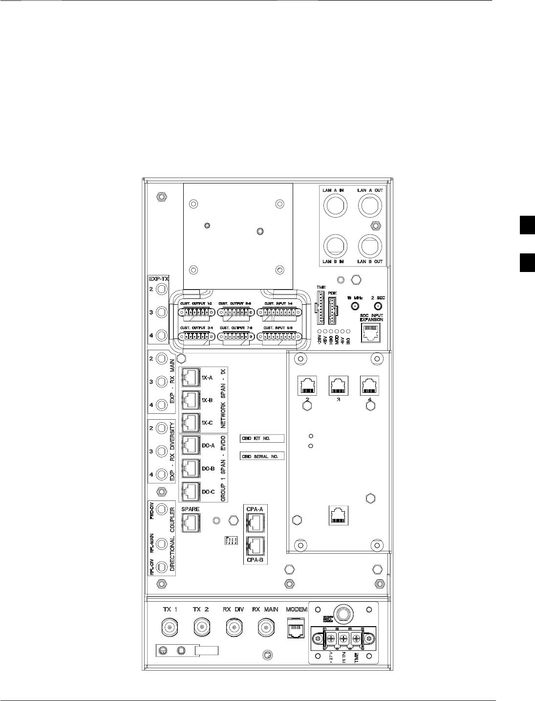
Connector Locations
Jun 2004 4-3
1X SC480 BTS Hardware Installation, Optimization/ATP, and FRU
DRAFT
Connector Locations
Figure 4-1 shows the location of the cable connectors on the BTS. The
system configuration determines which connectors are used. Figure 4-2
is a detail of the connectors on the rear of the BTS.
Figure 4-1: Rear View of BTS
RGPS Connector and
SDCX Module are
shown.
Note:
1. The LAN Connections
should be terminated with
50–Ohm loads.
2. The Expansion TX and RX
ports should be terminated
with SMA 50–Ohm loads.
ti–cdma–wp–00311–v01–ildoc–ah
DAISY–CHAIN SYNC – OUT
SDCX KIT NO.
SDCX SERIAL NO.
DAISY–CHAIN POWER
SDCX POWER
EXPANSION FRAME SYNC – OUT
RF–GPS IN
PWR
25
25A
4
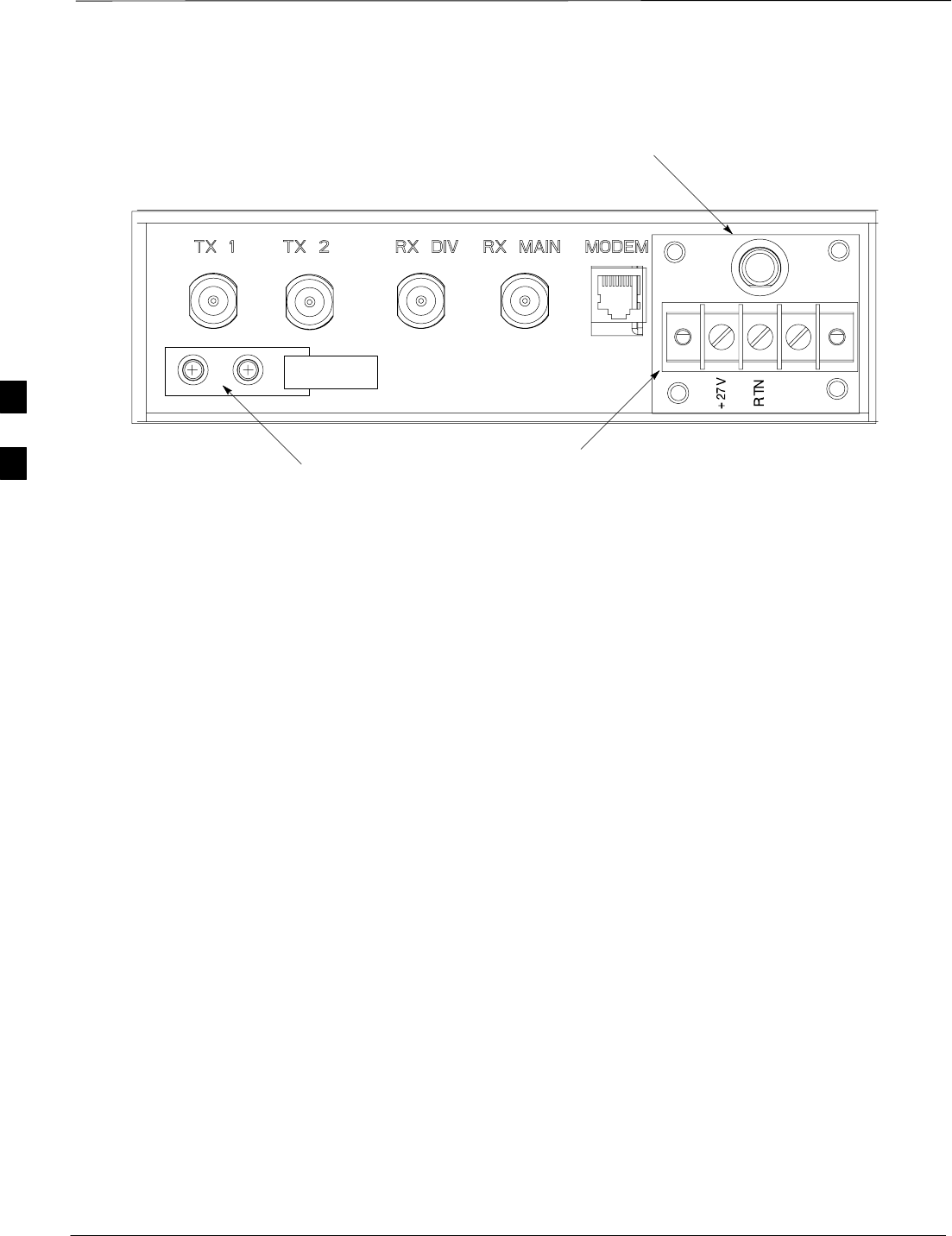
Connector Locations – continued
DRAFT
1X SC480 BTS Hardware Installation, Optimization/ATP, and FRU Jun 2004
4-4
Figure 4-2: Detail of Antenna Connectors and DC Power (Rear of BTS)
Circuit Breaker
DC Power
Terminal Strip
GROUND
Location and
GROUND LUG
TME
25A 25
Indoor/Outdoor Configuration
Connectors
cCLPA Connectors and Conduit Locations
Refer to Figure 4-7 for connectors and conduit locations
Outdoor Configuration
Connectors
TME Connectors and Conduit Locations
Refer to Figure 4-16 for connectors and conduit locations
PDE Conduit Locations
Refer to Figure 4-23 for conduit locations
4

Attaching BTS to Mounting Rack
Jun 2004 4-5
1X SC480 BTS Hardware Installation, Optimization/ATP, and FRU
DRAFT
Objective
The objective of this procedure is to attach the BTS to the Rack.
Background
The mounting plate is attached to the Rack, then a mounting bracket is
attached to the BTS. Finally, the BTS is attached to the Mounting Plate.
Required Tools and Materials
The following tools and materials are required to attach the BTS to the
Mounting Plate.
STorque driver wrench, 1/4–in. hex female drive, 0–10 N–M
ST30 Star tamper bit
SThree (3) M6X16 screws (Motorola Part No. 0310907D03)
SThree (3) isolation washers (Motorola Part No. 4309874U03)
SSix (6) customer supplied rack screws (Check manufacturer’s
specifications)
4
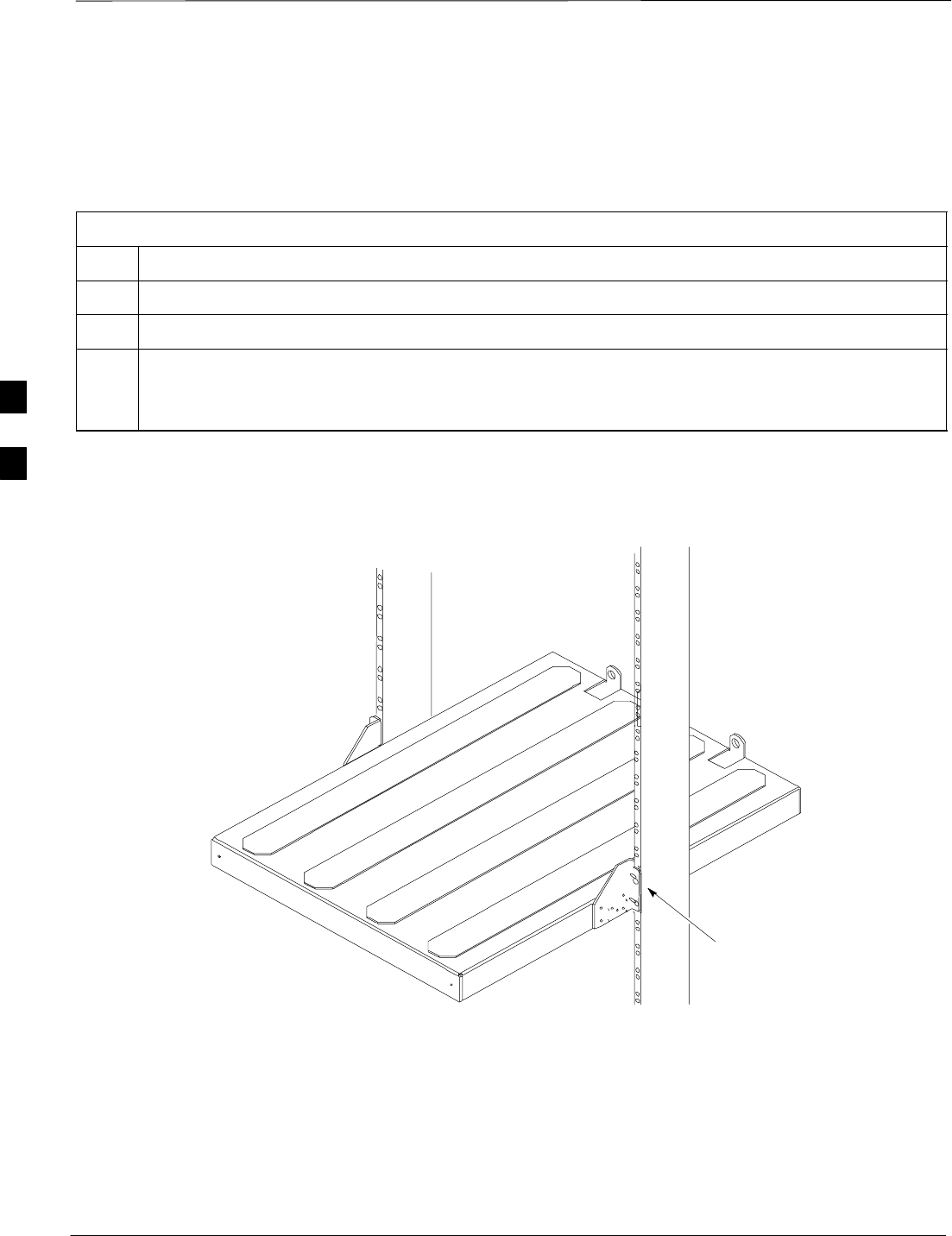
Attaching BTS to Mounting Rack – continued
DRAFT
1X SC480 BTS Hardware Installation, Optimization/ATP, and FRU Jun 2004
4-6
Procedure to Attach Mounting
Plate to Rack
Follow the procedure in Table 4-1 to attach the Mounting Plate to the
Rack. Refer to Figure 4-3.
Table 4-1: Procedure to Attach Mounting Plate to Rack
Step Action
1Determine where in the rack the Mounting Plate is to be attached.
2Ensure that the mounting plate is level.
3Set Mounting Plate similar to what is shown in Figure 4-3.
Attach Mounting Plate to Rack using four (4) customer supplied rack screws. Torque screws to
manufacturer’s specifications.
ti–cdma–wp–00301–v01–ildoc–ah
Figure 4-3: Attaching Mounting Plate to Rack
Four (4) rack screws
are required for
attching mounting plate
to rack. Two per side.
4
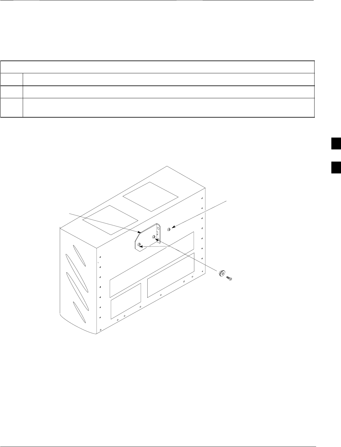
Attaching BTS to Mounting Rack – continued
Jun 2004 4-7
1X SC480 BTS Hardware Installation, Optimization/ATP, and FRU
DRAFT
BTS Mounting Bracket
Perform the procedure in Table 4-2 to attach the bracket to the BTS.
Table 4-2: Procedure to Attach BTS Mounting Bracket
Step Action
1Atttach mounting bracket as indicated in Figure 4-4.
2Using two (2) isolation washers and 2 M6 screws securely attach the mounting bracket to the forward
most holes on the BTS. Torque screws to 5 N–M (44 in–lbs).
MOUNTING
BRACKET
ti–cdma–wp–00302–v01–ildoc–ah
2 M6 SCREWS &
2 ISOLATION
WASHERS
Figure 4-4: Attaching Mounting Bracket to BTS
Hole not used.
4
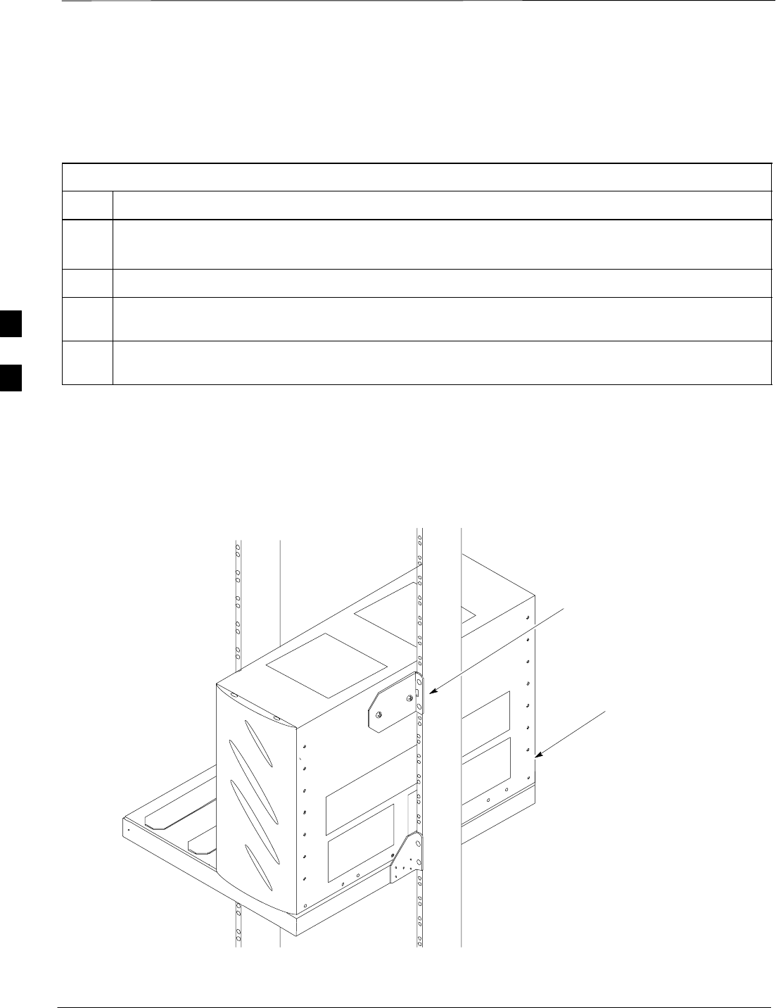
Attaching BTS to Mounting Rack – continued
DRAFT
1X SC480 BTS Hardware Installation, Optimization/ATP, and FRU Jun 2004
4-8
BTS to Mounting Plate
Perform the procedure in Table 4-3 to attach the BTS to the Mounting
Plate.
Table 4-3: Procedure to Attach BTS to Mounting Plate
Step Action
NOTE
The Compact BTS weighs 12 Kg (22 lbs).
1Place BTS on Mounting Plate as indicated in Figure 4-5. BTS bracket holes align with rack holes.
2Secure BTS bracket to rack using two (2) customer supplied screws. Torque screws to manufacturer’s
specification.
3At the rear of the BTS, use one M6 screw and isolation washer to secure the BTS to the mounting
plate. Torque screw to 5 N–M (44 in–lbs).
ti–cdma–wp–00303–v01–ildoc–ah
Figure 4-5: Attaching BTS to Mounting Plate
Two (2) rack screws are
required for attaching
BTS to rack.
One (1) M6 screw and
isolation washer is
required to attach BTS
to rack. See Figure 4-6.
4
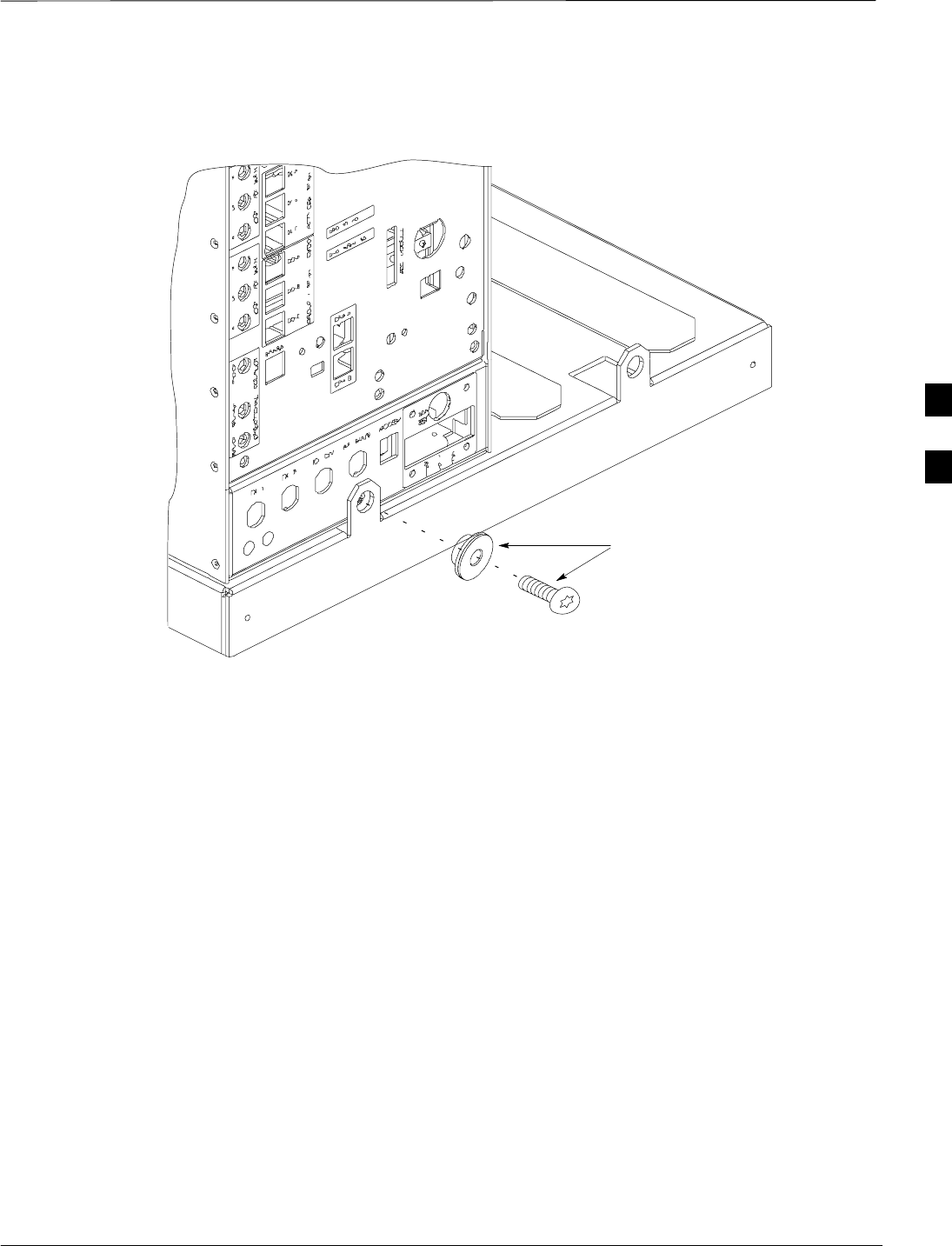
Attaching BTS to Mounting Rack – continued
Jun 2004 4-9
1X SC480 BTS Hardware Installation, Optimization/ATP, and FRU
DRAFT
Figure 4-6: BTS Rear Attachment
One M6 screw and
isolation washer for
attaching BTS to
mounting plate.
ti–cdma–wp–00305–v01–ildoc–ah
4
Compact Combined Linear Power Amplifier Installation
DRAFT
1X SC480 BTS Hardware Installation, Optimization/ATP, and FRU Jun 2004
4-10
Objective
This section contains general information for installing a Compact
Combined Linear Power Amplifier (cCLPA).
Cable Description
The following cable in Table 4-4 is necessary to do this procedure.
Table 4-4: DC Input Cable Description and Part Number
Cable Qty. Part Number Description
F 1 Customer
Supplied DC input cable with crimped lugs, 8–10 AWG, 10 m, designed for
+20 to +34 VDC power input.
Required Tools
The following are the tools required :
STorque driver wrench, 1/4–in. hex female drive, 0–10 N–m
ST20 Torx Tamper Bit, 1/4–in. hex
ST30 Torx Tamper Bit, 1/4–in. hex
SWire Crimping Tool
Indoor cCLPA Installation
The cCLPA is mounted directly to a 19–inch rack. Placement of cCLPA
is up to the customer. The maximum allowable TX cable loss (including
surge arrestor) from the cCLPA to the BTS is 2.0 dB for 800 MHz and
3.0 dB for 1.9 GHz. The maximum allowable RX cable loss (including
surge arrestor) from the cCLPA to the BTS is 3.0 dB.
The 1.9 GHz cCLPA receives +20 to +34 VDC from the DC power
source.
4
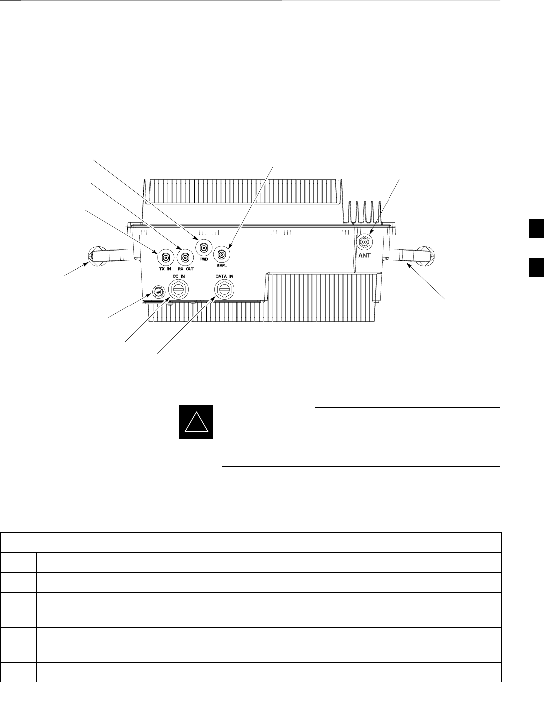
Compact Combined Linear Power Amplifier Installation – continued
Jun 2004 4-11
1X SC480 BTS Hardware Installation, Optimization/ATP, and FRU
DRAFT
cCLPA Connectors
Figure 4-7 shows the location of the cCLPA connectors.
REMOVABLE
HANDLE
ti–cdma–wp–00298–v01–ildoc–ah
DC INPUT
DATA INPUT
RX OUT
TX INPUT
FORWARD REFLECTED
ANTENNA
20A Circuit
Breaker
REMOVABLE
HANDLE
Figure 4-7: Bottom View of cCLPA
The cCLPA requires its own DC power source that is
different than the power source assigned to the Compact
BTS.
IMPORTANT
*
cCLPA Mounting Procedure
Follow the procedure in Table 4-5 to attach the cCLPA to the rack.
Table 4-5: Procedure to Mount the Power Amplifier
Step Action
1Place two screws (one each on each side of the rack). See Figure 4-8.
2Holding onto handles, mount the cCLPA onto the two screws.
Secure cCLPA to rack using 4 screws. See Figure 4-8. Torque screws to to10 N–M (88 in–lbs).
NOTE
Handles of cCLPA may be removed if mounting space is limited.
3Remove 2 screws each securing handles to cCLPA prior to mounting.
4
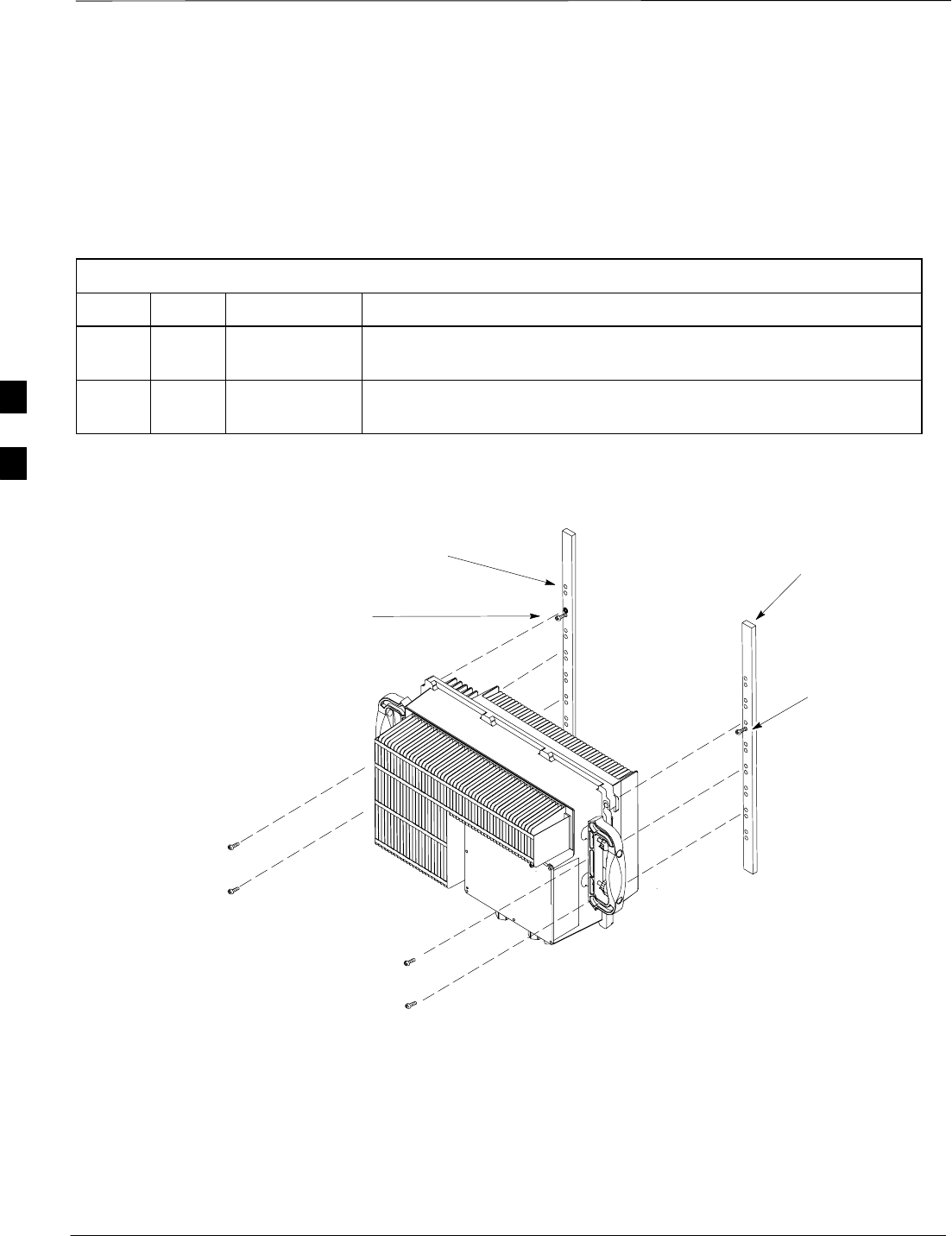
Compact Combined Linear Power Amplifier Installation – continued
DRAFT
1X SC480 BTS Hardware Installation, Optimization/ATP, and FRU Jun 2004
4-12
cCLPA Grounding
Cable Description
Since the length of this cable varies from site to site, no specific length is
assigned. Table 4-6 lists the components required to build a ground
cable.
Table 4-6: Ground Cable and Lug Description and Part Number
Cable Qty. Part Number Description
A 1 Customer
Supplied Ground cable, 6 -AWG, insulated copper wire.
1 Customer
Supplied Two Hole, Long Barrel lug connector, 6 AWG, 1/4–inch diameter,
5/8–inch stud hole spacing, 13/32 Tang width.
Figure 4-8: cCLPA Mounting to Rack
Rack
Screws
Screws
Mounting Hole
Location for
cCLPA
Screw for
Mounting
cCLPA
Screw for
Mounting
cCLPA
4
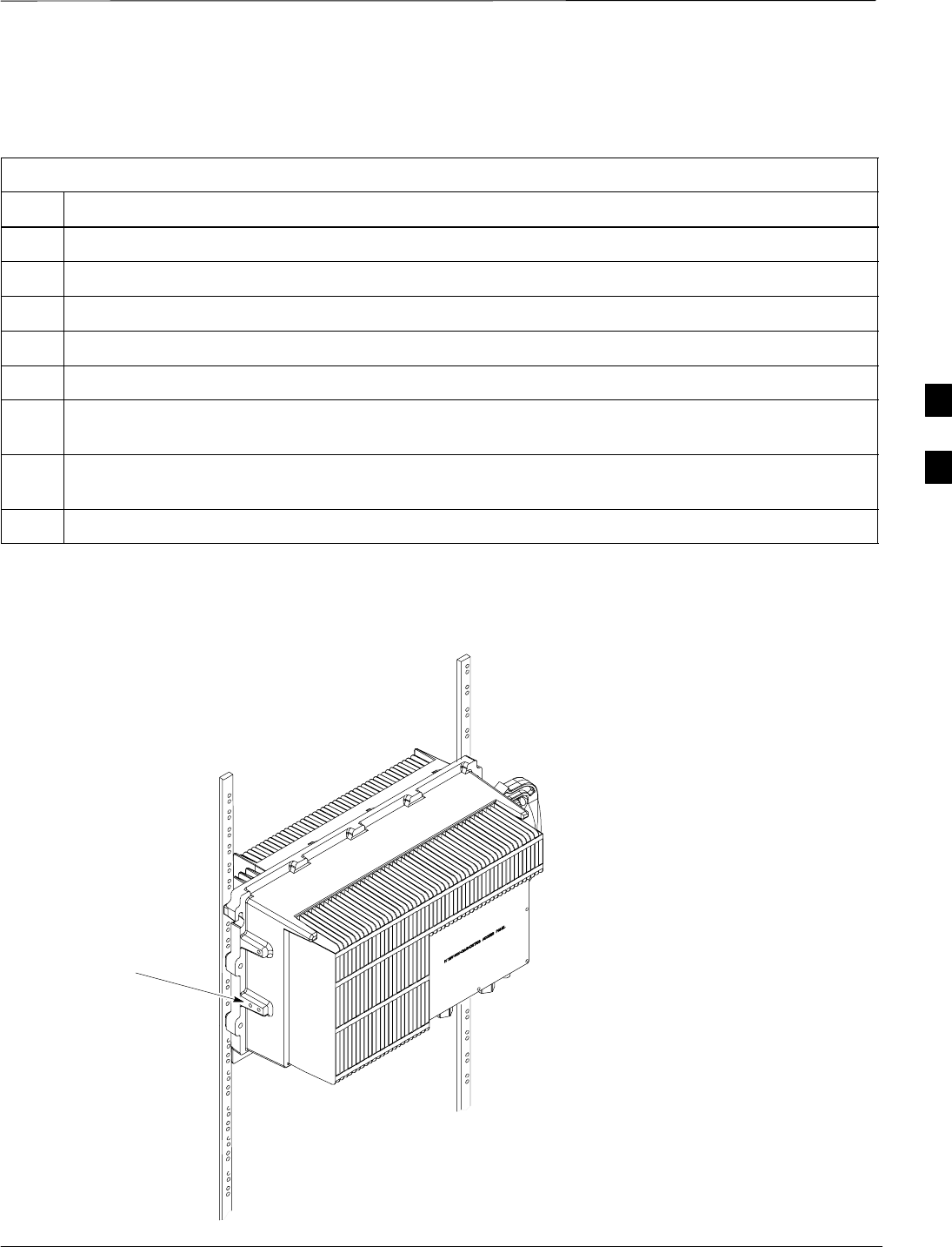
Compact Combined Linear Power Amplifier Installation – continued
Jun 2004 4-13
1X SC480 BTS Hardware Installation, Optimization/ATP, and FRU
DRAFT
Follow the procedure in Table 4-7 to attach the ground cable to the
cCLPA.
Table 4-7: Procedure to Ground the cCLPA
Step Action
1If not already done, remove handles from cCLPA.
2Retrieve ground lug and cabling.
2a Using a wire stripper, trim back 1/2–inch of the ground cable insulation from each end.
2b Using a crimp tool crimp the lug onto one end of the cable.
2c Attach the ground clamp to the opposite end of the ground cable.
3Using one screw attach the ground cable and lug to one of the holes left vacant by the removal of the
handles. See Figure 4-9.
4Slide ground clamp over ground anchor and secure using a lockwasher. Use a 13mm socket to tighten
the hex nut. Use a torque wrench to tighten hex nut to 10.0 N–M (88 in–lbs).
5Use tie–wraps as required to dress the ground cable.
After handle is
removed attach
ground lug
ti–cdma–wp–00361–v01–ildoc–ah
Figure 4-9: cCLPA Grounding
4

Compact Combined Linear Power Amplifier Installation – continued
DRAFT
1X SC480 BTS Hardware Installation, Optimization/ATP, and FRU Jun 2004
4-14
DC Power Connection
Procedure
A +27 VDC power source is required to supply the cCLPA. Follow the
procedure in Table 4-8 to attach the DC Power cable to the cCLPA.
Table 4-8: Procedure to Attach DC Power Cable to the cCLPA
Step Action
1Set DC Power source circuit breaker to OFF.
2Route cable (F) from DC Power source to the cCLPA. See Figure 4-10
3Remove 8 screws securing I/O Panel cover and remove.
4Route cable through connector to DC Power Terminal Block. See Figure 4-10.
5If not already loosened, loosen DC Power Terminal Block screws.
6Strip approximately 12 mm (1/2–inch) of sheathing from the end of each wire.
7Insert the ”+” wire (red) into the “+” opening of the DC Power Terminal Block, then secure it by
tightening the screw. Torque screw to 2.3 N–M (20 in–lbs).
8Perform step 6 for the “–” wire.
9Insert the “–” wire (blue) into the “–” opening of the DC Power Terminal Block, then secure it by
tightening the screw. Torque screw to 2.3 N–M (20 in–lbs).
10 If the Data Cable is not installed, proceed to Table 4-11; otherwise, proceed to Table 5-6 for
Pre–Power up Test.
4
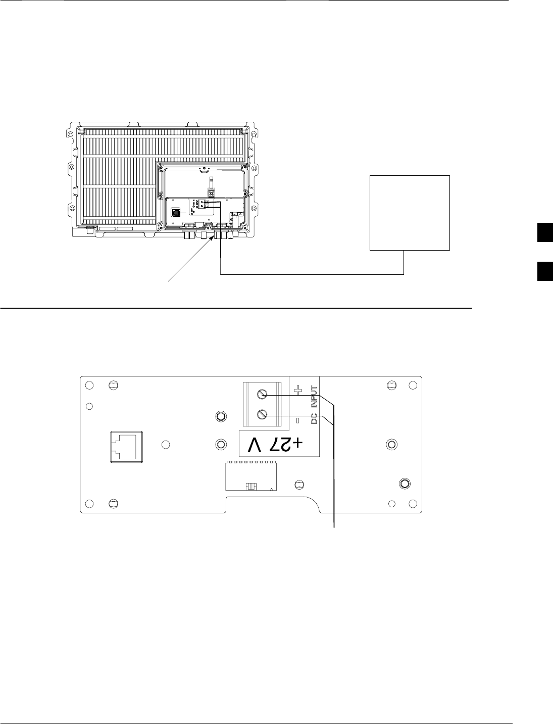
Compact Combined Linear Power Amplifier Installation – continued
Jun 2004 4-15
1X SC480 BTS Hardware Installation, Optimization/ATP, and FRU
DRAFT
Figure 4-10: DC Power Connection to cCLPA
+27 VDC CABLE
Separate DC
Power Source
cCLPA
DC IN
CONNECTOR
Close In View of +27 V cCLPA I/O
Board DC Power Connection
ti–cdma–wp–00297–v01–ildoc–ah
(F)
Data Cable Description and
Part Number
Table 4-9 lists the cable required to perform this procedure. Since the
cable length will vary from site to site, it will be left to the customer to
build the data cable desired.
4
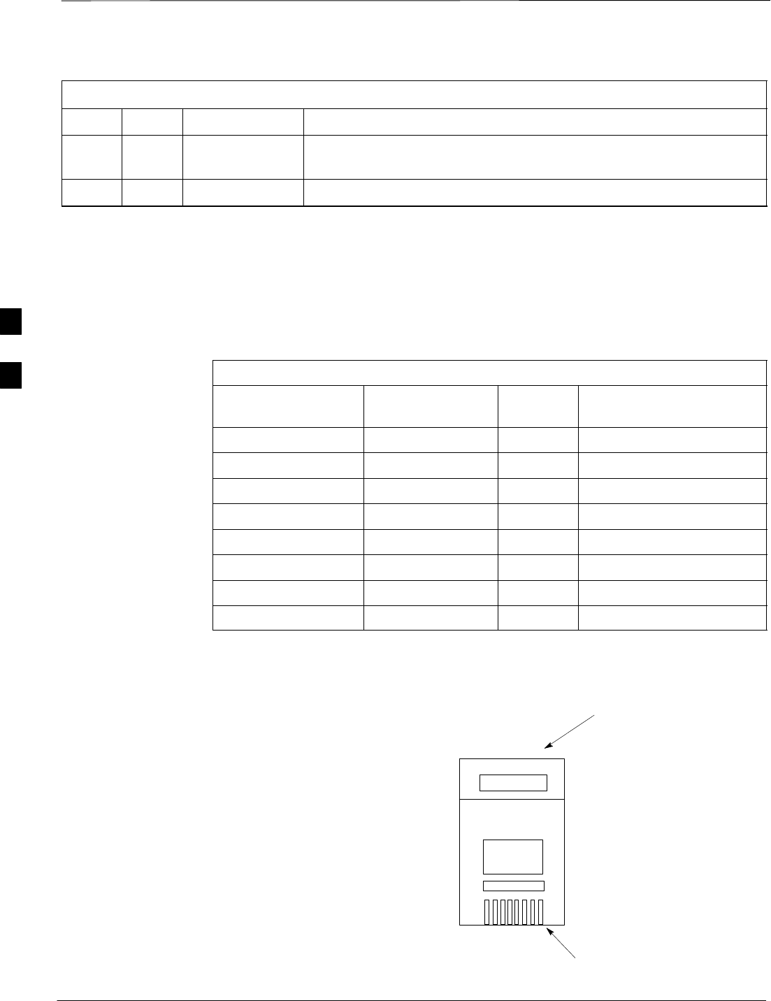
Compact Combined Linear Power Amplifier Installation – continued
DRAFT
1X SC480 BTS Hardware Installation, Optimization/ATP, and FRU Jun 2004
4-16
Table 4-9: Data Cable Description and Part Number
Cable Qty. Part Number Description
G 1 Customer
Supplied RJ45 cable for BTS to cCLPA
1 7687717T02 Ferrite, clip–on core
Data Cable Wiring Information
Table 4-10 lists the wiring information required to manufacture the
CBIO–to–cCLPA Data Cable. Figure 4-11 shows the location of Pin 1
on the RJ45 connector.
Table 4-10: Data Cable Wiring Scheme
CBIO Signal Name Wire Color RJ45 Pin
Outs cCLPA Signal Name
Txx_ACT_P White/Orange 1 CLPA_485_TX_ACT_P
Txx_ACT_N Orange 2 CLPA_485_TX_ACT_N
CLPA_x_ADDR White/Green 3 CLPA_485_ADD_0
RxD_x_P Blue 4 CLPA_485_TX_A_P
RxD_x_N White/Blue 5 CLPA_485_TX_A_N
GROUND Green 6 GROUND
TxD_P White/Brown 7 CLPA_485_RX_A_P
TxD_N Brown 8 CLPA_485_RX_A_N
Figure 4-11: CBIO–to–cCLPA Data Cable RJ45
Connector
Pin 1
Wires inserted
in this end
4

Compact Combined Linear Power Amplifier Installation – continued
Jun 2004 4-17
1X SC480 BTS Hardware Installation, Optimization/ATP, and FRU
DRAFT
BTS Data Cable Connection
Procedure
Once the Data Cable has been built, follow the procedure in Table 4-11
to connect the BTS Data cable to the cCLPA.
Table 4-11: Procedure to Attach BTS Data Cable to cCLPA
Step Action
1If not already performed, remove 8 screws securing I/O Panel cover.
2Route BTS Data cable to the cCLPA. See Figure 4-12.
3Mate Data cable RJ45 plug to I/O Board RJ45 socket. See Figure 4-12. Table 4-10 identifies the data
cable wiring.
4If there are two cCLPAs in use, bundle cables together and place ferrite core around cables. Ensure
that the cables are not being pinched before closing and latching the ferrite core.
5Slide ferrite core as close to the BTS connectors as possible without causing stress. Use a tie–wrap on
the ferrite core side away from the connector. The tie–wrap holds the ferrite core in place
6Install I/O Panel Cover and secure using 8 screws. Torque screws to 2.3 N–M (20 in–lbs).
4
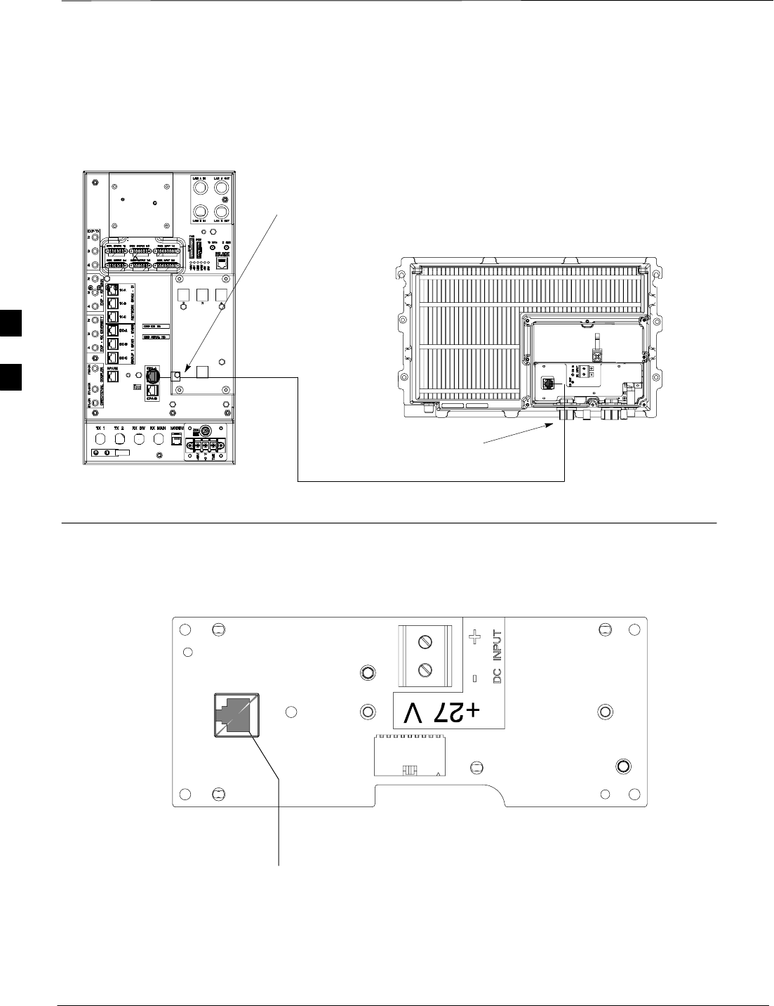
Compact Combined Linear Power Amplifier Installation – continued
DRAFT
1X SC480 BTS Hardware Installation, Optimization/ATP, and FRU Jun 2004
4-18
Figure 4-12: Data Cable Connection Diagram for Compact BTS to cCLPA
NOTE:
1. Not to scale.
2. Ferrite bead is used in
indoor configuration
only
Compact BTS
To cPA–A
Connector
on CBIO
DATA IN
CONNECTOR
DATA CABLE
Close In View of cCLPA I/O Board Data Cable
Connection
To RJ45 Connector on
cCLPA I/O Board
Ferrite Core
RF–
GP
D IN
P
W
R
4

Compact Combined Linear Power Amplifier Installation – continued
Jun 2004 4-19
1X SC480 BTS Hardware Installation, Optimization/ATP, and FRU
DRAFT
Outdoor cCLPA Installation
The cCLPA is mounted on a bracket assembly and secured to a pole.
Placement of cCLPA is up to the customer. The cCLPA is already
weatherproofed, so there are no special weather related precautions
required for outdoor installation. The maximum allowable TX cable loss
(including surge arrestor) from the cCLPA to the BTS is 2.0 dB for 800
MHz, and 3.0 dB for 1.9 GHz. The maximum allowable RX cable loss
(including surge arrestor) from the cCLPA to the BTS is 3.0 dB.
The 800 MHz cCLPA operates on –60 t0 –40 VDC supplied by the
Power Distribution Enclosure (PDE). The 1.9 GHz cCLPA operates on
+20 to +35 VDC supplied by the Power Distribution Enclosure (PDE).
Pole or Wall Mounting cCLPA
Follow the procedure in Table 4-12 to pole or wall mount the cCLPA.
Table 4-12: Procedure to Pole or Wall Mount the cCLPA
Step Action
1Determine where on the pole or structure the cCLPA will be mounted. Consult site configuration
documentation as required.
2For wall or other such structure, proceed to step 2a. For pole mount, proceed to step 2c.
2a Using the Wall Mounting Bracket as a template, drill starter holes, using the wider of the two sets
present. Screw in one each M6 anchor bolt in the upper holes.
2b Hang Wall Mounting Bracket on anchor bolts. Install remaining anchor bolts and secure bracket by
tightening the 4 M6 anchor bolts. Torque anchor bolts to 10 N–M (88 in–lbs). Proceed to step 3.
2c Center the Wall Mounting Bracket on Pole Mounting Bracket Assembly and install the 4 M6 screws in
the narrower of the two sets of holes present. Secure bracket by tightening the 4 M6 screws. Torque
screws to 10 N–M (88 in–lbs). Proceed to step 3. See Figure Figure 4-13.
3Install two M6 screws in the top holes of the Wall Mounting Bracket.
n WARNING
It is recommended that two people hang the cCLPA onto the Wall Mounting Bracket.
4Hang cCLPA and install remaining 4 M6 screws. Secure cCLPA to bracket by tightening screws.
Torque screws to 10 N–M (88 in–lbs).
5If not already done, remove handles from cCLPA.
6Perform Table 4-7 to install the ground cable.
4
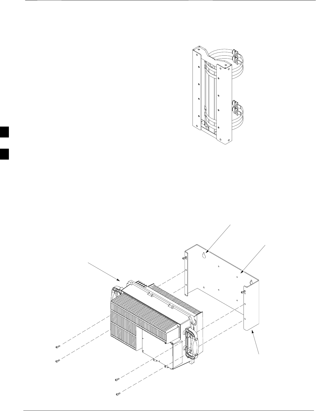
Compact Combined Linear Power Amplifier Installation – continued
DRAFT
1X SC480 BTS Hardware Installation, Optimization/ATP, and FRU Jun 2004
4-20
Figure 4-13: Pole Mounting BracketAssembly
Figure 4-14 shows the cCLPA being attached to the Wall Mounting
Bracket. Reference Figure 4-13 for the Pole Mounting Bracket
Assembly.
Figure 4-14: Wall Mounting Bracket and cCLPA
cCLPA
ti–cdma–wp–00278–v01–ildoc–ah
Wall Mounting Bracket
For wall mount
For pole mount
4
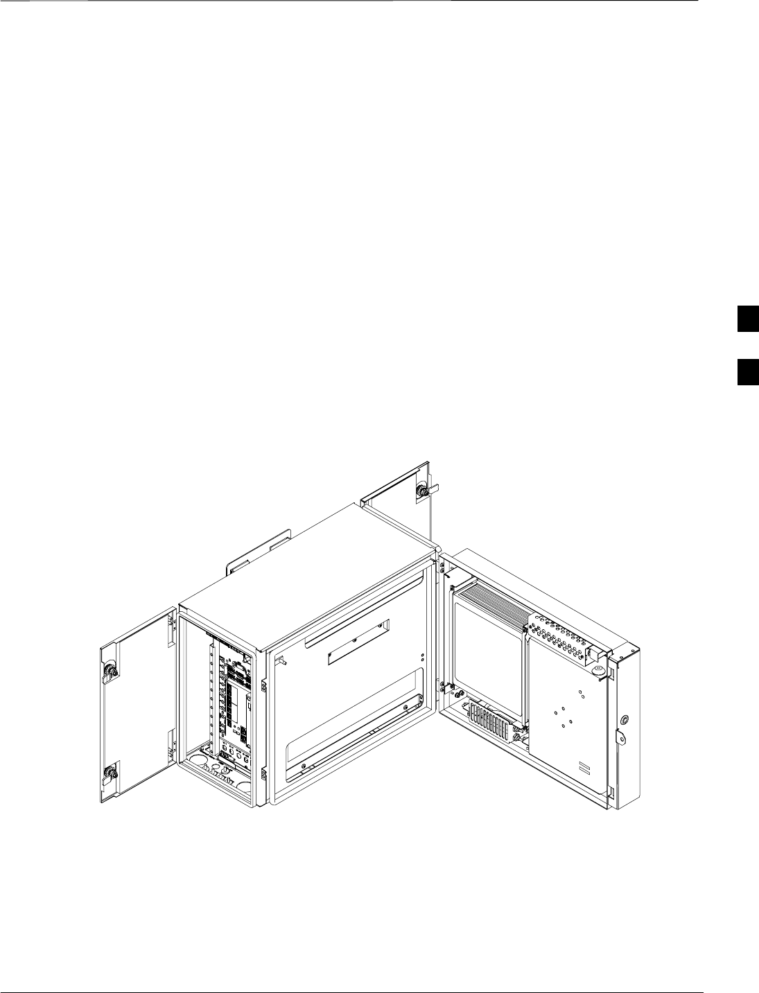
Thermal Management Enclosure Installation
Jun 2004 4-21
1X SC480 BTS Hardware Installation, Optimization/ATP, and FRU
DRAFT
Objective
This section contains general information for installing a Thermal
Management Enclosure (TME). These procedures are utilized if the
BTS site is configured for outdoor use.
The purpose of the TME (Figure 4-15) is to protect the BTS from the
weather. The Compact BTS is installed in the TME and some cables are
connected to interior TME connectors, while others are routed out
through access holes. Figure 4-17 shows the Wall Mounting Bracket and
Pole Mounting Bracket Assembly.
The TME can be pole or wall mounted. The Heat Management System
(HMS) is attached to the TME and is used to regulate temperature within
the TME.
The TME is replaced as a whole should damage to the exterior no longer
allow protection from the environment or if damage should occur to the
TME connectors .
Figure 4-15: Thermal Management Enclosure and Heat Management System
ti–cdma–wp–00320–v01–ildoc–a
h
Electrical Requirements
The TME is powered by DC voltage that has been converted from an AC
power source by the PDE or from battery backup routed through the
PDE. Power required is –48VDC nominal, range is –60 to –40 VDC.
4
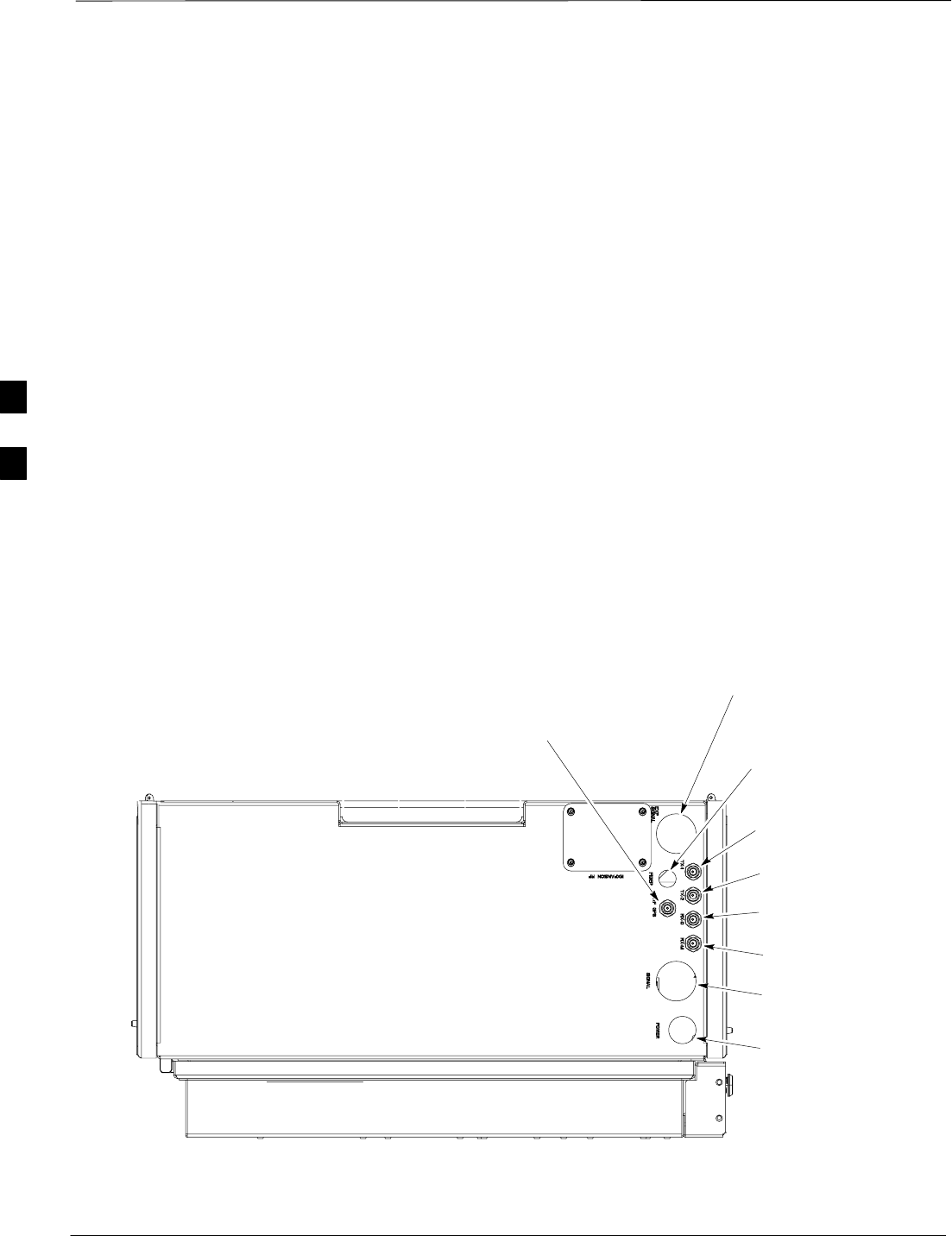
Thermal Management Enclosure Installation – continued
DRAFT
1X SC480 BTS Hardware Installation, Optimization/ATP, and FRU Jun 2004
4-22
Environmental Requirements
The following lists the environmental requirements of the TME:
SOperate Temperature: –50° to +75°C
SStorage Temperature: –40° to +60°C
SOperating/Storage Humidity: 10 to 95%, non–condensing
SCold Start: –40° to 0°C
SSeismic: Per Telecordia GR–63–CORE Zone 4
Weight Requirement
STME: 18 kg (40 lbs)
SHeat Management System: 11.5 kg (26 lbs)
SWall Mounting Bracket: 2.5 kg (5.5 lbs)
TME Connectors and Conduit
Locations
Figure 4-16 shows the connectors and conduit locations
Figure 4-16: Bottom View of TME
ti–cdma–wp–00321–v01–ildoc–ah
TX 1
Connector
TX 2
Connector
RX DIV
Connector
RX MAIN
Connector
FIBER OPTICS
Conduit Location
POWER Cable
Conduit Location
DATA Cable
Conduit Location
RF–GPS
Connector
EXPANSION Cable
Conduit Location
1
2
1
3
4
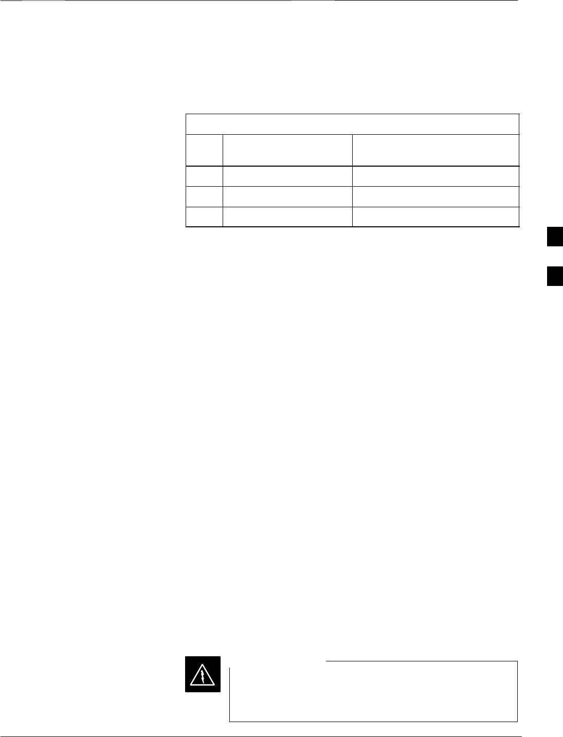
Thermal Management Enclosure Installation – continued
Jun 2004 4-23
1X SC480 BTS Hardware Installation, Optimization/ATP, and FRU
DRAFT
TME Conduit Sizes
The following are the conduit sizes required for connecting to the TME.
Reference Figure 4-16.
Table 4-13: TME Conduit Sizes
No. Designation Required Size
(Inches)
1Data and Expansion 1–1/2
2TME Power Input 1
3Fiber Optic 1/2
Materials
Tools
The following tools are required to install the TME:
STorque Screwdriver
SDrill, 3/8–inch or 1/2–inch drive
SAppropriate concrete or wood drill Bits
STie–Wraps
SAppropriate size conduit (Metallic sealtight)
SBucklestrap Cutting Tool (Motorola P/N 6604809N01)
SSafety Glasses
SHeavy Gloves
SElectrical Tape
STape Measure
SHammer, ball–peen
TME Installation
Pole Mount
Follow the procedure in Table 4-14 to pole mount the TME. Figure 4-17
shows the Mounting Bracket Assembly and Wall Mounting Bracket.
Check site documents to verify that pole and supporting hardware are
capable of handling the load created by mounting the BTS system.
Once TME is installed, DO NOT use it as a step ladder. It
will not support a person standing on top or hanging from
it.
WARNING
4

Thermal Management Enclosure Installation – continued
DRAFT
1X SC480 BTS Hardware Installation, Optimization/ATP, and FRU Jun 2004
4-24
Table 4-14: Procedure to Pole Mount the TME
Step Action
1Slide non–buckle end of strap through openings in Pole Mounting Bracket Assembly.
2Set Pole Mounting Bracket Assembly with straps at the desired height.
NOTE
Initial height is determined by customer. The bottom of the TME is a minimum of 1 meter from the
ground. Adjust Pole Mounting Bracket Assembly to account for this minimum distance.
3Wrap strap around the pole, slide non–buckle end through strap loop and pull snug.
4Attach Bucklestrap Cutting Tool (slide strap through openings in tool, pull gripper lever to slide strap
into spindle head), slide tool towards buckle. Place cutting tool end of tool as close to the buckle as
possible.
NOTE
The strap can be cut to a more manageable length prior to using the tool. Bucklestrap Cutting Tool is a
ratchet spindle and cutter in one.
5Turn spindle clockwise until strap is tight.
6Use cutter lever to cut strap.
7Using the tool bend the strap over towards the buckle .
8Remove tool and use a hammer to bend the strap more.
9Use the hammer to bend buckle tabs over strap.
10 Use electrical tape to cover over the buckle and straps.
11 Perform step 3 through step 10, for the remaining straps.
12 Secure Wall Mounting Bracket to Pole Mounting Bracket Assembly using 8 M6 screws. Torque
screws to 3.4 N–M (30 in–lbs). See Figure 4-17.
n WARNING
The TME weighs 22 kg (48 lbs). One person is able to mount the TME on the Wall Mounting Bracket.
It is recommended that two people or one person using a mechanical lift to mount the TME onto
mounting bracket.
Do not place the Compact BTS inside the TME prior to placing it on the mounting bracket.
Remove the HMS prior to mounting the TME.
13 Set the TME onto the Wall Mounting Bracket. Ensure that it rests in the slots of the Wall Mounting
Bracket. See Figure 4-17.
14 Secure the TME to the mounting bracket using 6 M6 screws. Torque screws to 3.4 N–M (30 in–lbs).
See Figure 4-18.
4
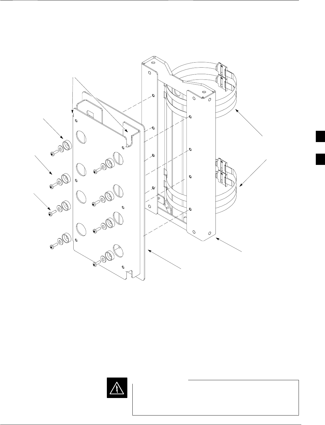
Thermal Management Enclosure Installation – continued
Jun 2004 4-25
1X SC480 BTS Hardware Installation, Optimization/ATP, and FRU
DRAFT
Figure 4-17: Wall Mounting Bracket and Pole Mounting Bracket Assembly
ti–cdma–wp–00317–v01–ildoc–ah
Slots for hanging the TME
Isolation Pad
Isolation
Washer
Shoulder
Washer
M6
Screw
Pole
Mounting
Straps
Pole Rest
Wall Mount
Follow the procedure in Table 4-15 to wall mount the TME. Refer to
Figure 4-17 for the Wall Mounting Bracket. Check site documents to
verify that wall structure and supporting hardware are capable of
handling the load created by mounting the BTS system.
Once TME is installed, DO NOT use it as a step ladder. It
will not support a person standing on top or hanging from
it. DO NOT mount HMS and leave it in the open position.
WARNING
4

Thermal Management Enclosure Installation – continued
DRAFT
1X SC480 BTS Hardware Installation, Optimization/ATP, and FRU Jun 2004
4-26
Table 4-15: Procedure to Install Mounting Bracket on a Wall
Step Action
1Select a suitable wall position such that the bottom of the TME is a minimum of 1 meter above the
ground.
NOTE
Check site documentation for further information.
2Position Wall Mounting Bracket on wall and mark hole locations.
3Drill starter holes for the anchor bolts.
4Secure Wall Mounting Bracket to wall using 8 M6 anchor bolts. Torque anchor bolts to 3.4 N–M (30
in–lbs).
n WARNING
The TME weighs 18 kg (40 lbs). One person is able to mount the TME on the Wall Mounting Bracket.
It is recommended that two people or one person using a mechanical lift mount the TME onto
mounting bracket.
Do not place the Compact BTS inside the TME prior to placing it on the mounting bracket.
Do not attach HMS to the TME prior to mounting the TME.
5Hang TME on Wall Mounting Bracket. Mounting bar on the rear of the TME is set into the cutouts on
the Wall Mounting Bracket.
6Secure the TME to the Wall Mounting Bracket using 6 M6 screws. Torque screws to 3.4 N–M (30
in–lbs). See Figure 4-18.
4
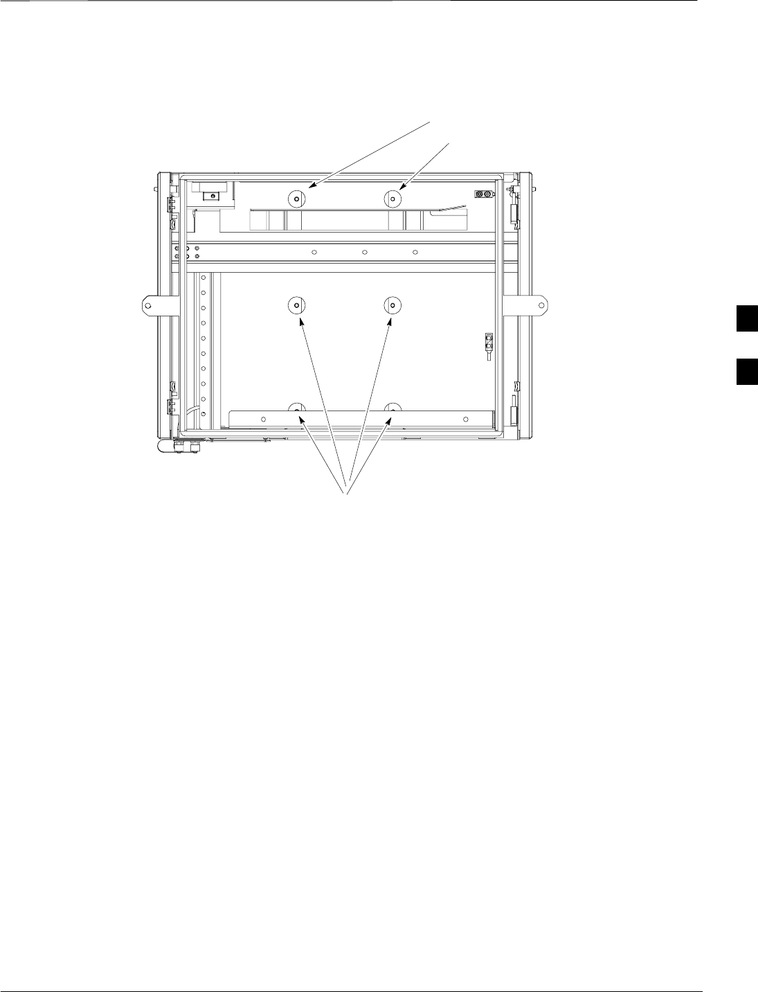
Thermal Management Enclosure Installation – continued
Jun 2004 4-27
1X SC480 BTS Hardware Installation, Optimization/ATP, and FRU
DRAFT
Figure 4-18: TME Screw Mounting Location
Screw Hole
Location
Screw Hole Locations
ti–cdma–wp–00334–v01–ildoc–ah
4
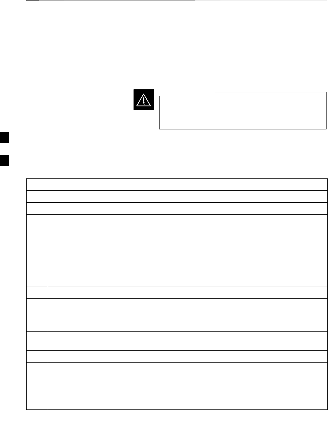
Compact BTS and HMS Installation
DRAFT
1X SC480 BTS Hardware Installation, Optimization/ATP, and FRU Jun 2004
4-28
Objective
This section contains general information for installing a Compact BTS
in a Thermal Management Enclosure (TME).
Once the outdoor enclosures are installed, they are not to
be used as steps or other types of climbing aids. They
were not designed to support a person.
WARNING
Compact BTS Installation
Follow the procedure in Table 4-16 to install the BTS inside the TME.
Table 4-16: Procedure to Install Compact BTS in a TME
Step Action
1Verify that the TME is securely fastened to the mounting bracket.
2Lift and slide the Compact BTS into the TME (See Figure 4-19).
n WARNING
The Compact BTS weighs 25 kg (55 lbs). One person is able to mount the BTS inside the TME. It is
recommended that two people or one person using a mechanical lift mount the BTS inside the TME.
3Once placed in the proper position, slide the Compact BTS inside the TME.
4Secure the Compact BTS to the TME with 5 M6 screws. (See Figure 4-19). Torque screws to 3.4 N–M
(30 in–lbs).
5If not already open, unlock and open the left–hand door to the TME.
! CAUTION
Ensure that DC power to TME/BTS is disengaged.
6Attach ground lug (part of TME) to BTS using two M6 screws.
7Remove protective cover from BTS DC Power connector and connect DC power cable from TME
Power Distribution Assembly.
8Connect the “+” wire (red, marked +27V) to the +27 V terminal.
9Connect the “–” wire (black, marked RETURN) to the RETURN terminal.
10 Connect the blue wire (marked TME) to the TME terminal.
11 Connect the TX and RX cables to the appropriate TME connectors.
12 Connect RGPS or Local GPS (RF–GPS) cable to CBIO.
4
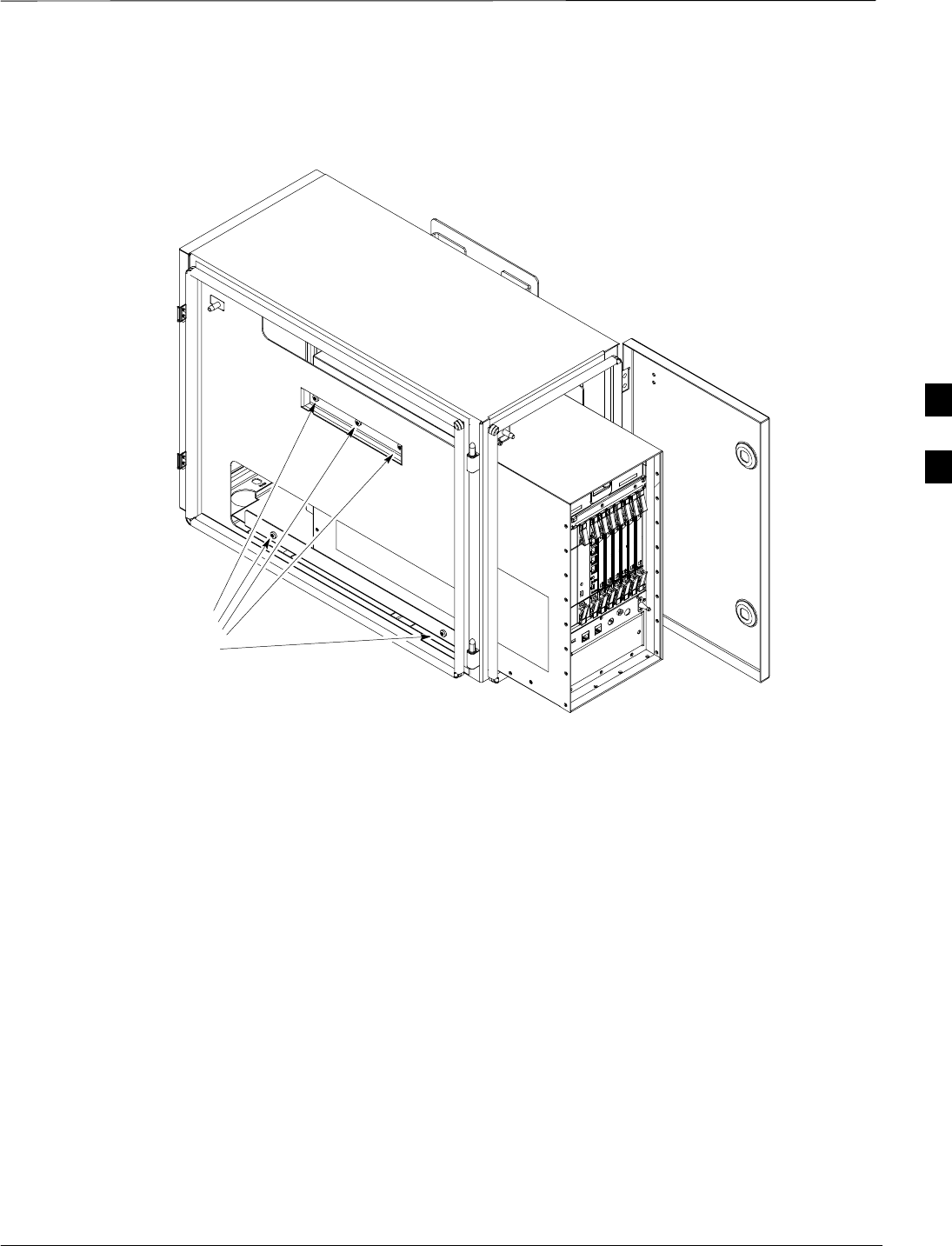
Compact BTS and HMS Installation – continued
Jun 2004 4-29
1X SC480 BTS Hardware Installation, Optimization/ATP, and FRU
DRAFT
Figure 4-19: Thermal Management Enclosure and BTS
ti–cdma–wp–00262–v01–ildoc–a
h
Once BTS is in place
install M6 screws at
these locations
HMS is removed for
clarity.
4
Compact BTS and HMS Installation – continued
DRAFT
1X SC480 BTS Hardware Installation, Optimization/ATP, and FRU Jun 2004
4-30
HMS Installation
In an outdoor configuration, the HMS module is part of the Thermal
Management Enclosure (TME). It is external to the TME and its
purpose is to regulate the heating and cooling of the Compact BTS
within the TME. See Figure 4-20.
Figure 4-20: Heat Management System (HMS)
INTERIOR VIEW
ti–cdma–wp–00318–v01–ildoc–ah
ti–cdma–wp–00319–v01–ildoc–ah
EXTERIOR VIEW
Follow the procedure in Table 4-17 to install the Heat Management
System (HMS).
Table 4-17: Procedure to Install the HMS
Step Action
1Once the TME and BTS are installed, attach the HMS to the TME.
NOTE
HMS weighs 11.5 kg (26 lbs).
table continued on next page
4
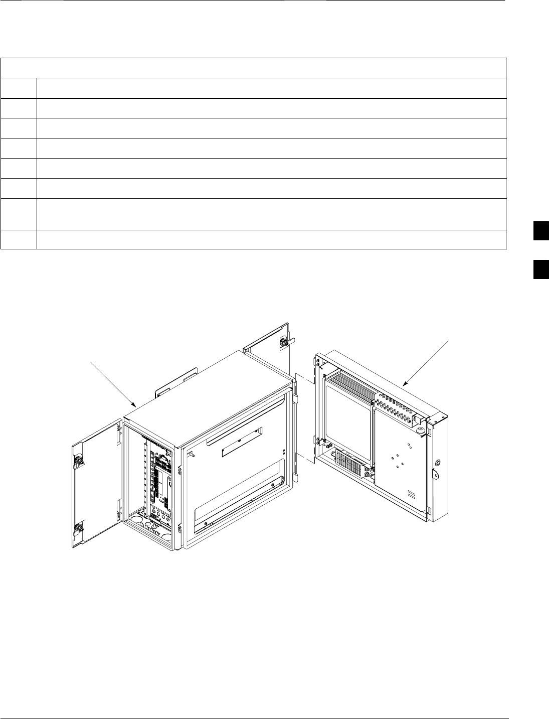
Compact BTS and HMS Installation – continued
Jun 2004 4-31
1X SC480 BTS Hardware Installation, Optimization/ATP, and FRU
DRAFT
Table 4-17: Procedure to Install the HMS
Step Action
2Set the HMS on the hinges located on the TME (See Figure 4-21).
3Use a driver wrench with socket to attach ground lug to HMS ground connection.
4Connect the Data/DC PowerCable to HMS controller.
5Dress cables as necessary.
6Ensure that door swings freely and does not pinch any cables.
7Close HMS and secure using the two draw latches. Fold draw latch handles down. Verify that HMS is
fully closed and seated.
8Close draw latch door and lock using key.
Figure 4-21: HMS Installation
ti–cdma–wp–00320–v02–ildoc–ah
Set HMS on TME hinges.
HMS
TME
4
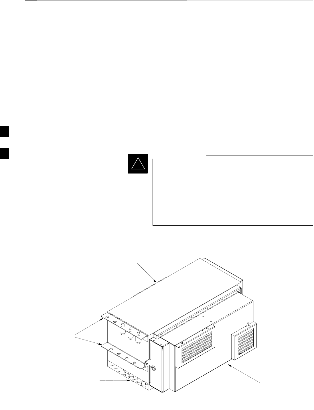
Power Distribution Enclosure Installation
DRAFT
1X SC480 BTS Hardware Installation, Optimization/ATP, and FRU Jun 2004
4-32
Objective
This section contains general information for installing a Power
Distribution Enclosure (PDE) with Heat Exchanger (HX). See
Figure 4-22.
The optional PDE is a stand–alone unit external to the TME.
When in use, the PDE provides Primary surge for input power, customer
alarms, GPS, external antenna(s) and span lines; in addition to AC/DC
power conversion for the SC480 base unit and optional external PAs.
If battteries are used as backup, their cabling is routed to the PDE.
The present manual contains high level information on only one of two
manufacturer’s of the PDE.
Motorola does not recommend the PDE be used to support
indoor configuration The PDE is not configurable for
indoor sites, and in general, it does not locate surge
protection functions appropriately for indoor cellsites.
For indoor, power and surge protection functions should be
implemented according to Standards and Guidelines for
Communication Sites using telecom–grade third party
equipment that is available through the ancillary group.
IMPORTANT
*
Figure 4-22: PDE and Heat Exchanger
ti–cdma–wp–00336–v01–ildoc–ah
PDE
HX
Brackets for
Antenna Surge
Arrestors
Ground Location
4
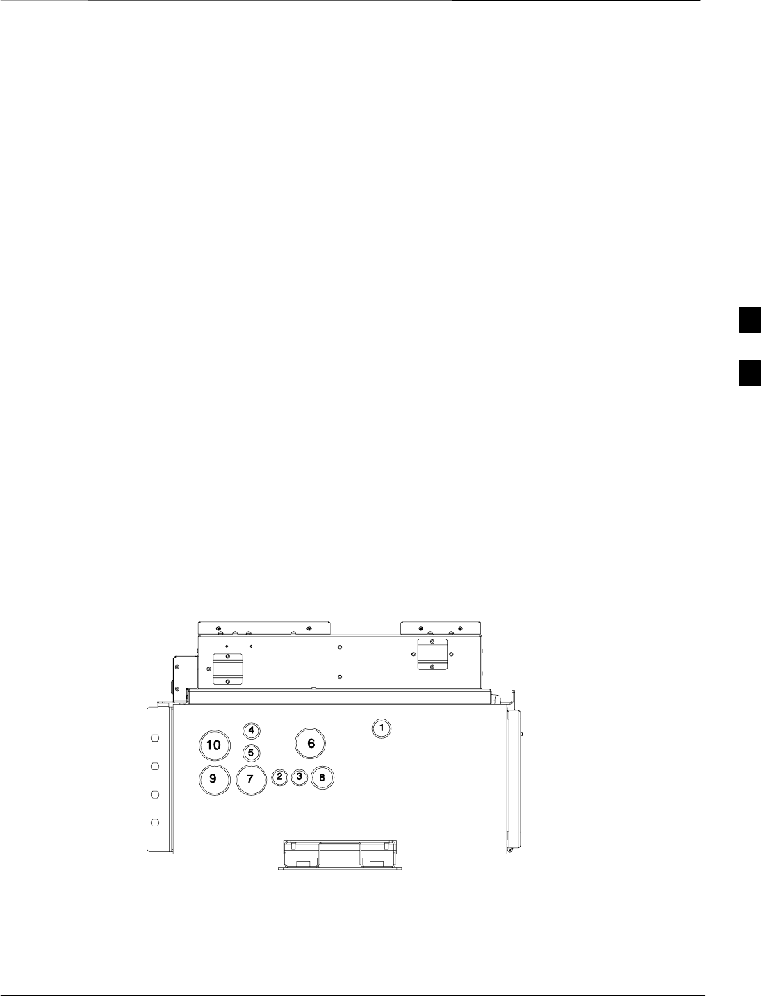
Power Distribution Enclosure Installation – continued
Jun 2004 4-33
1X SC480 BTS Hardware Installation, Optimization/ATP, and FRU
DRAFT
Electrical
The PDE is powered by AC voltage (customer supplied) in the range
154–286 VRMS at 47–63 Hz at 3100 Watts.
The PDE outputs –54 Vdc at 2000 Watts (China).
The PDE outputs +30 VDC at 2000 Watts (Domestic)
Batteries if used, are located in a customer supplied external cabinet.
Environmental
The following lists the environmental requirements of the PDE:
SOperate Temperature: –40° to +50°C
SStorage Temperature: –40° to +60°C
SOperating/Storage Humidity: 10 to 95%, non–condensing
SCold Start: –40° to 0°C
SSeismic: Per Telecordia GR–63–CORE Zone 4
Weight
SPDE: 52 kg (115 lbs)
– PDE cabinet: 25 kg (55 lbs)
– Heat Exchanger: 12 kg (26 lbs)
– Power Supply Module (PSM): 5 kg (11 lbs)
– Miscellaneous: 10 kg (22 lbs)
Figure 4-23: PDE Conduit Location
1 – PDE Power Input (AC) 6 – Battery Power (DC & TP)
2 – Compact PA #1 Power (DC) 7 – Expansion PDE (TP)
3 – Compact PA #2 Power (DC) 8 – TME Power (DC)
4 – Compact PA #1 Signal (TP) 9 – PDE Signal (TP)
5 – Compact PA #2 Signal (TP) 10 – Customer I/O (TP)
ti–cdma–wp–00338–v01–ildoc–ah
4

Power Distribution Enclosure Installation – continued
DRAFT
1X SC480 BTS Hardware Installation, Optimization/ATP, and FRU Jun 2004
4-34
PDE Conduit Sizes
The following are the conduit sizes required for connecting to the PDE.
Reference Figure 4-23.
Table 4-18: Conduit Sizes
No. Designation Required Size
(Inches)
1PDE Power Input 3/4
2Compact PA #1 Power 1/2
3Compact PA #2 Power 1/2
4Compact PA #1 Signal 1/2
5Compact PA #2 Signal 1/2
6Battery Power 1–1/2
7Expansion PDE 1–1/2
8TME Power 1
9TME Signal 1–1/2
10 Customer I/O 1–1/2
4
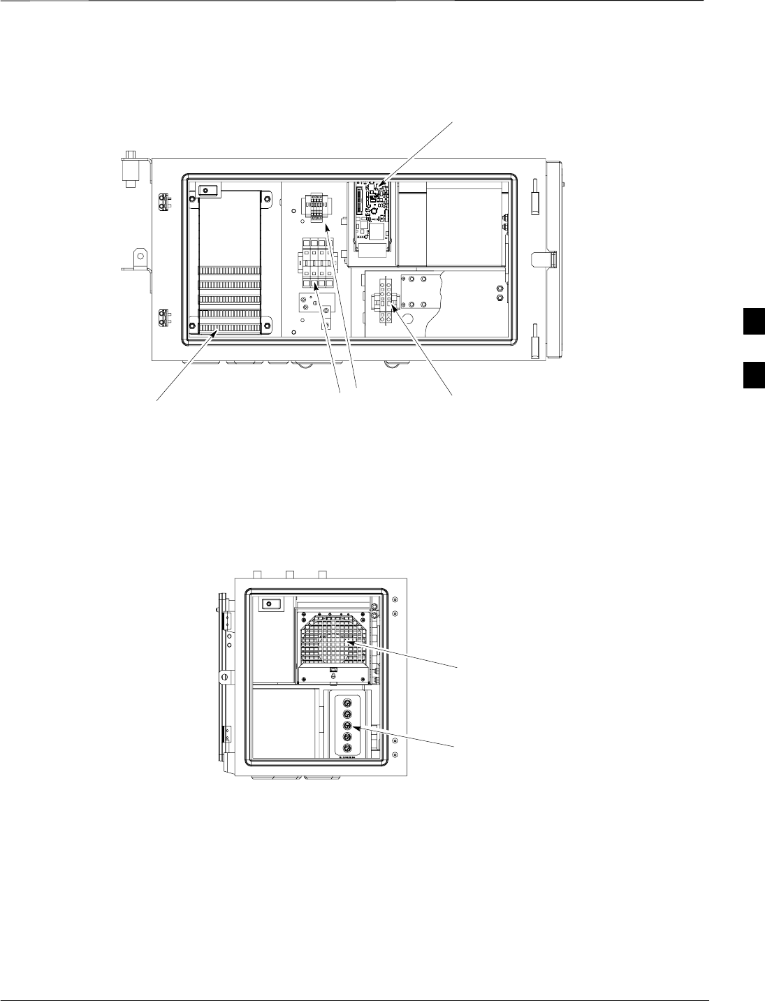
Power Distribution Enclosure Installation – continued
Jun 2004 4-35
1X SC480 BTS Hardware Installation, Optimization/ATP, and FRU
DRAFT
Figure 4-24: PDE Detail
Power Supply
Module
DC Circuit Breakers
Could be buttons or
switches
AC Terminal Block
DC Output
Terminal Block
Punch Block
Power Management
Alarms Card (PMAC)
ti–cdma–wp–00359–v01–ildoc–ah
ti–cdma–wp–00345–v01–ildoc–ah
4
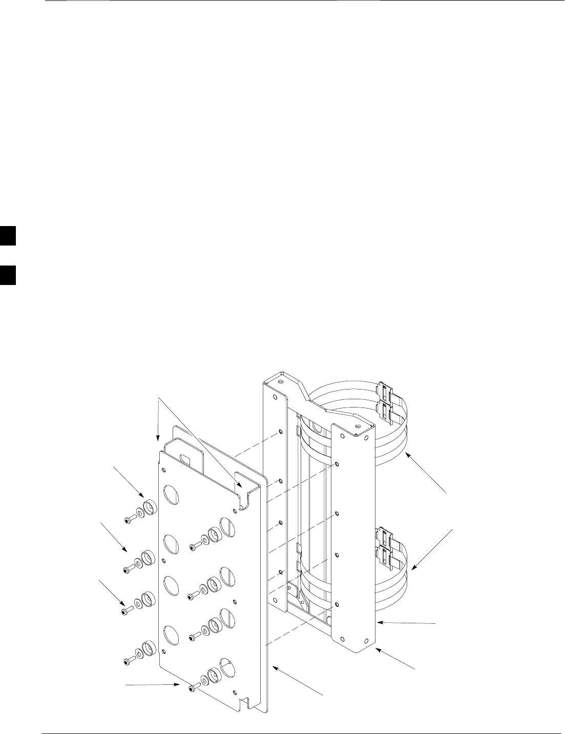
Power Distribution Enclosure Installation – continued
DRAFT
1X SC480 BTS Hardware Installation, Optimization/ATP, and FRU Jun 2004
4-36
Materials
Tools
The following tools are required to install the PDE:
STorque Screwdriver
SDrill, 3/8–inch or 1/2–inch drive
SAppropriate concrete or wood drill Bits
STie–wraps
SAlarms connector, 8–pin in–line, (Tyco, part number 103958–7)
customer supplied
SBucklestrap Cutting Tool (Motorola P/N 6604809N01) for pole
mounting bracket assembly
PDE Installation
Figure 4-25 shows the Wall Mounting Bracket. and Mounting Bracket
Assembly.
Slots for hangging the PDE
Isolation
Pad
Isolation
Washer
Shoulder
Washer
M6 Screw
Pole
Mounting
Straps
Pole Rest
Figure 4-25: Wall Mounting Bracket and Pole Mounting Bracket Assembly
ti–cdma–wp–00317–v01–ildoc–ah
Wall Mounting
Bracket
Pole Mounting
Bracket Assembly
4
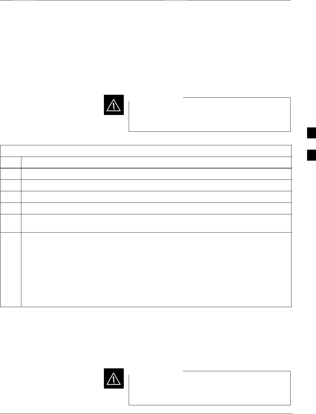
Power Distribution Enclosure Installation – continued
Jun 2004 4-37
1X SC480 BTS Hardware Installation, Optimization/ATP, and FRU
DRAFT
Mounting Bracket Assembly
Procedure
Pole Mount
Follow the procedure in Table 4-19 to install the pole mounting bracket
assembly and wall mounting bracket for pole mounting the PDE.
Once PDE is installed, DO NOT use it as a step ladder. It
will not support a person standing on top or hanging from
it.
WARNING
Table 4-19: Procedure to Install Mounting Bracket Assembly on a Pole
Step Action
1Wrap the mounting bracket straps around the pole to gauge the proper length.
2Cut straps to proper length.
3Slide straps through slots in mounting bracket assembly.
4Secure mounting bracket to pole using the straps.
5Secure Wall Mounting Bracket to Pole Mounting Bracket Assembly using 8 M6 bolts. Torque bolts to
3.4 N–M (30 in–lbs).
n WARNING
The PDE (less HX) weighs 25 kg (55 lbs) . It is recommended that a minimum of two people or one
person using a mechanical lift mount the PDE.
Remove the Heat Exchanger prior to mounting the PDE.
NOTE
Initial height is determined by customer. Minimum height from the ground is 1 meter.
6Hang PDE on Wall Mounting Bracket and secure using 4 M6 screws. Torque screws to 3.4 N–M (30
in–lbs).
Wall Mount
Follow the procedure in Table 4-20 to install the Wall Mounting Bracket
on a wall for the PDE.
Once PDE is installed, DO NOT use it as a step ladder. It
will not support a person standing on top or hanging from
it.
WARNING
4

Power Distribution Enclosure Installation – continued
DRAFT
1X SC480 BTS Hardware Installation, Optimization/ATP, and FRU Jun 2004
4-38
Table 4-20: Procedure to Install the Wall Mounting Bracket on a Wall
Step Action
1Select a suitable wall position such that the bottom of the PDE is a minimum of 1 meter above the
ground.
NOTE
Check site documentation for further information.
2Position Wall Mounting Bracket on wall and mark hole locations.
3Drill starter holes for the anchor bolts.
4Secure Wall Mounting Bracket to wall using 8 M6 anchor bolts. Torque anchor bolts to 3.4 N–M (30
in–lbs).
5Unlock and open PDE side door and remove Power Supply Module (PSM) and AC input cover prior
to mounitng PDE.
NOTE
Screw to secure PDE to Wall Mounting Bracket can only be seen with PSM removed.
n WARNING
The PDE (less HX) weighs 25 kg (55 lbs) . It is recommended that a minimum of two people or one
person using a mechanical lift mount the PDE.
Remove Heat Exchanger prior to mounting the PDE.
NOTE
Initial height is determined by customer. Minimum height from the ground is 1 meter.
6Hang PDE on Wall Mounting Bracket.
7Secure PDE to Wall Mounting Bracket using 4 M6 screws. Torque screws to 3.4 N–M (30 in–lbs). See
Figure 4-26.
8Install PSM after PDE is secured to Wall Mounting Bracket. AC cover may be left out for AC
connection later.
4
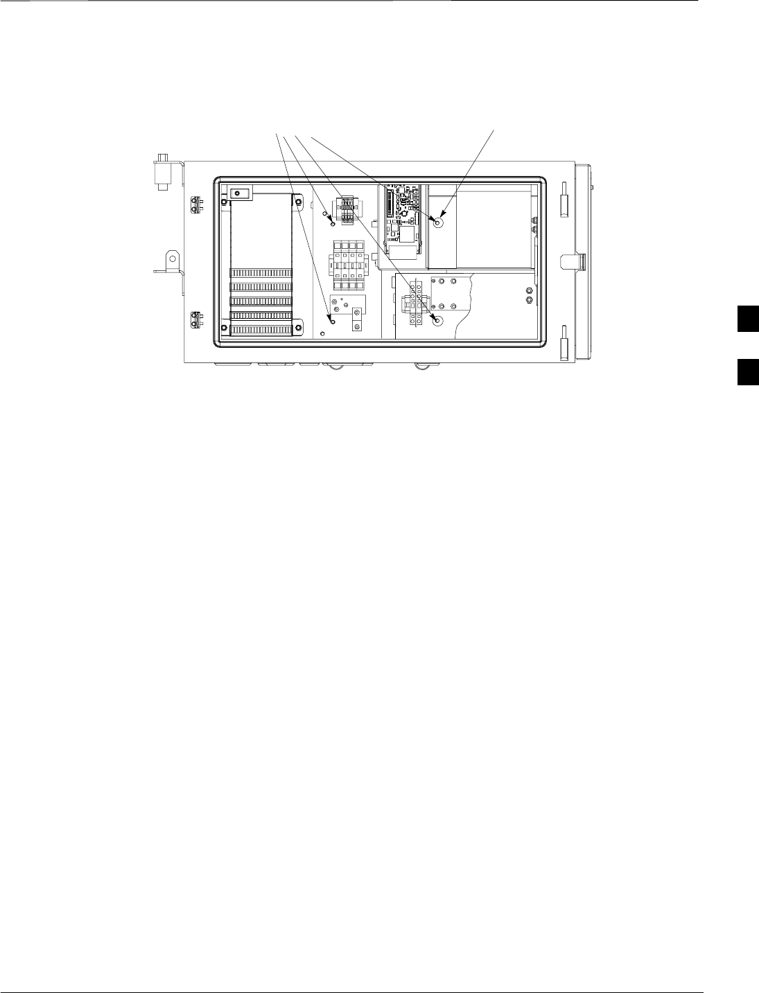
Power Distribution Enclosure Installation – continued
Jun 2004 4-39
1X SC480 BTS Hardware Installation, Optimization/ATP, and FRU
DRAFT
Figure 4-26: PDE Mounting Screw Locations
Screw Hole Location Screw can only be inserted if the
Power Converter is first removed.
4
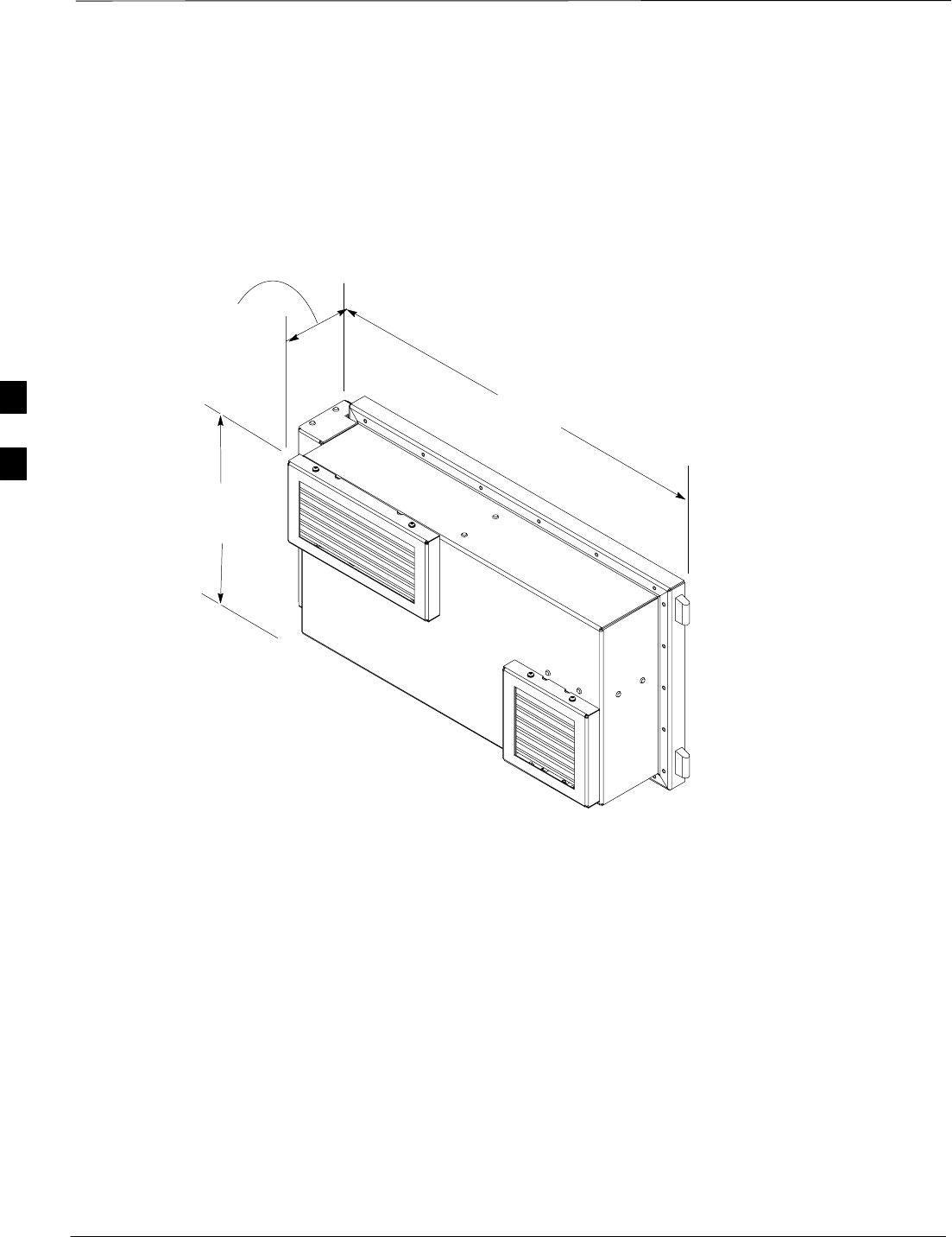
Power Distribution Enclosure Installation – continued
DRAFT
1X SC480 BTS Hardware Installation, Optimization/ATP, and FRU Jun 2004
4-40
Heat Exchanger
The Heat Exchanger (HX) is attached to the PDE and provides
temperature regulation. Figure 4-27 shows the HX.
Figure 4-27: PDE Heat Exchanger Dimensions
700 mm
140 mm
300 mm
ti–cdma–wp–00339–v01–ildoc–ah
4
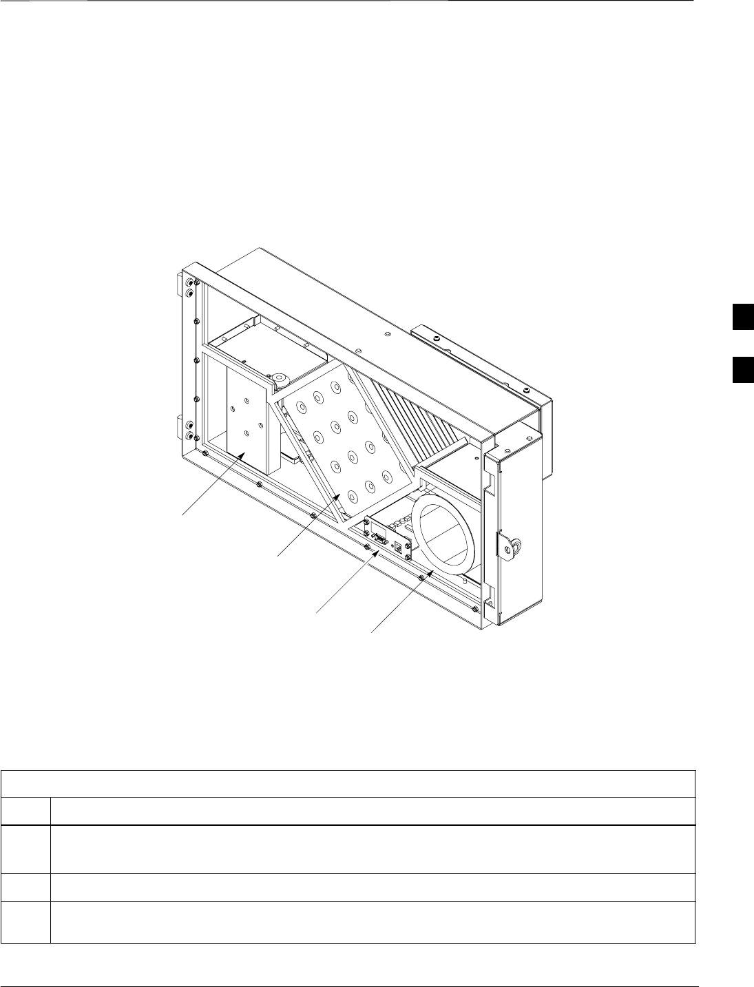
Power Distribution Enclosure Installation – continued
Jun 2004 4-41
1X SC480 BTS Hardware Installation, Optimization/ATP, and FRU
DRAFT
Heat Exchanger Details
Figure 4-28 shows the main components of the HX.
Figure 4-28: PDE Heat Exchanger Detail
Controller
Internal Loop
Inlet Blower
Internal Loop
Exhaust Blower
Internal Shield removed for clarity
Core
Heat Exchanger Installation
Follow the procedure in Table 4-21 to install the Heat Exchanger.
Table 4-21: Procedure to Install the Heat Exchanger
Step Action
NOTE
The HX weighs 12 kgs (26 lbs). One person is able to lift the HX and place it on the PDE.
1Once PDE is securely attached, place HX on hinges on the PDE.
2Connect Ground and DC/Alarm power, and RS232 Alarm cables. The Test connector should be
connected to a load.
table continued on next page
4
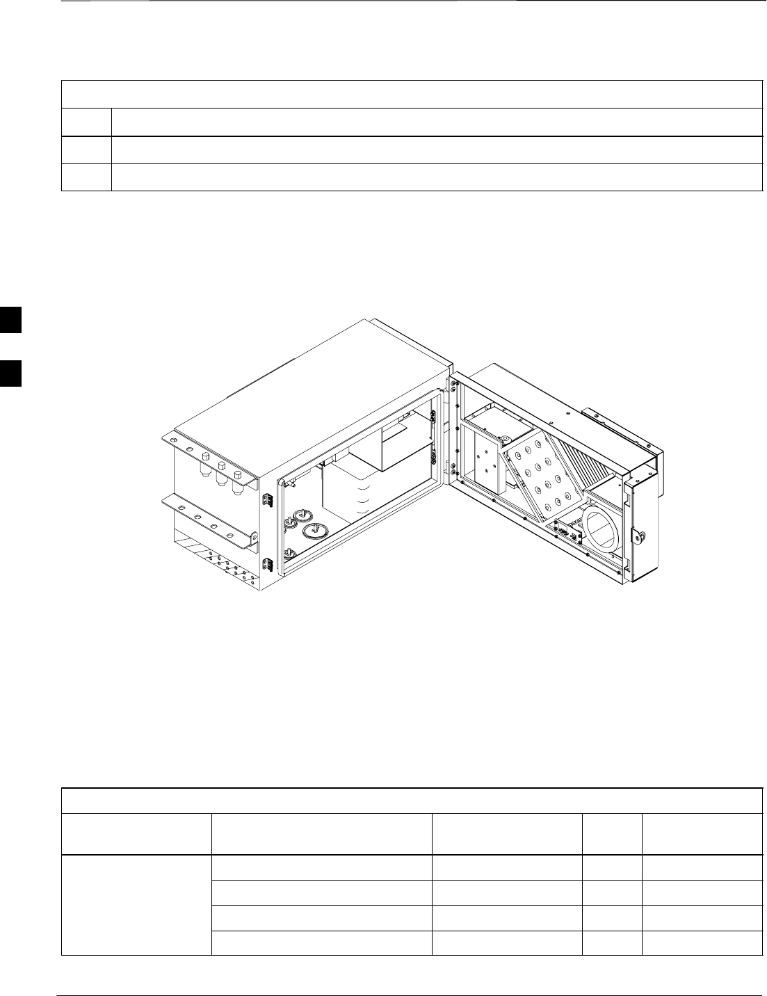
Power Distribution Enclosure Installation – continued
DRAFT
1X SC480 BTS Hardware Installation, Optimization/ATP, and FRU Jun 2004
4-42
Table 4-21: Procedure to Install the Heat Exchanger
Step Action
3Use tie–wraps to dress cables as necessary.
4Ensure that HX swings freely on the hinges and does not pinch any cable.
Figure 4-29: PDE and Heat Exchanger
Internal Shields removed for clarity
ti–cdma–wp–00342–v01–ildoc–ah
PDE Cabling
Table 4-22 shows the cabling pin–outs of the multiple layout
punchblock for the PDE. Consult manufacturer’s installation
specification for connecting wires to the punch block.
Use punchdown tool provided or an equivalent 110 punchdown tool.
Table 4-22: PDE Punchblock Wiring Descriptions
Unit Interface Signal Wire Color PB
Pin Output Pin
Customer Input CDI_1 101T
CDI_1_RTN 101R
CDI_2 102T
CDI_2_RTN 102R
table continued next page
4

Power Distribution Enclosure Installation – continued
Jun 2004 4-43
1X SC480 BTS Hardware Installation, Optimization/ATP, and FRU
DRAFT
Table 4-22: PDE Punchblock Wiring Descriptions
Unit Interface Output PinPB
Pin
Wire ColorSignal
CDI_3 103T
CDI_3_RTN 103R
CDI_4 104T
CDI_4_RTN 104R
CDI_5 105T
CDI_5_RTN 105R
CDI_6 106T
CDI_6_RTN 106R
CDI_7 107T
CDI_7_RTN 107R
CDI_8 108T
CDI_8_RTN 108R
Customer Output CDO NC_0 109T
CDO COM_0 109R
CDO NO_0 110T
CDO NC_1 110R
CDO COM_1 201T
CDO NO_1 201R
CDO NC_2 202T
CDO COM_2 202R
CDO NO_2 203T
CDO NC_3 203R
CDO COM_3 204T
CDO NO_3 204R
CDO NC_4 205T
CDO COM_4 205R
CDO NO_4 206T
CDO NC_5 206R
CDO COM_5 207T
CDO NO_5 207R
CDO NC_6 208T
table continued next page
4

Power Distribution Enclosure Installation – continued
DRAFT
1X SC480 BTS Hardware Installation, Optimization/ATP, and FRU Jun 2004
4-44
Table 4-22: PDE Punchblock Wiring Descriptions
Unit Interface Output PinPB
Pin
Wire ColorSignal
CDO COM_6 208R
CDO NO_6 209T
CDO NC_7 209R
CDO COM_7 210T
CDO NO_7 210R
RGPS DATA_FROM_HEAD_POS 301T
SYNC_FROM_HEAD_POS 301R
SYNC_TO_HEAD_POS 302T
DATA_TO_HEAD_POS 302R
RGPS_+28V 303T
RGPS_+28V 303R
DATA_FROM_HEAD_NEG 304T
SYNC_TO_HEAD_NEG 304R
SYNC_TO_HEAD_NEG 305T
DATA_TO_HEAD_NEG 305R
RGPS RTN 306T
RGPS RTN 306R
Combined Compact
Linear Power
CLPA_485_TX_ACT_P 307T
Linear Power
Amplifier 1 CLPA_485_TX_ACT_P 307R
CLPA_485_ADD_0 308T
CLPA_485_TX_A_P 308R
CLPA_485_TX_A_N 309T
GROUND 309R
CLPA_485_RX_A_P 320T
CLPA_485_RX_A_N 310R
Power Management
Enclosure
PDE_AC_FAILURE 401T
Enclosure
PDE_DOOR_ALARM 401R
PDE_HARD_FAILURE 402T
PDE_SOFT_FAILURE 402R
PDE_PRESENCE 403T
PDE_ALARM_RTN 403R
table continued next page
4

Power Distribution Enclosure Installation – continued
Jun 2004 4-45
1X SC480 BTS Hardware Installation, Optimization/ATP, and FRU
DRAFT
Table 4-22: PDE Punchblock Wiring Descriptions
Unit Interface Output PinPB
Pin
Wire ColorSignal
1X Span Line RX_RING_NET_A 404T
RX_TIP_NET_A 404R
TX_RING_NET_A 405T
TX_TIP_NET_A 405R
RX_RING_NET_B 406T
RX_TIP_NET_B 406R
TX_RING_NET_B 407T
TX_TIP_NET_B 407R
RX_RING_NET_C 408T
RX_TIP_NET_C 408R
TX_RING_NET_C 409T
TX_TIP_NET_C 409R
UNUSED 410T
UNUSED 410R
Battery Backup BAT_TP1_PRESENCE_DET 502T
BATT_TP1_PRESENCE_RTN 502R
BATT_TP2_+VE 503T
BATT_TP2_–VE 503R
BATT_TP2_PRESENCE_DET 504T
BAT_TP2_PRESENCE_RTN 504R
Combined Compact
Linear Power
CLPA_485_TX_ACT_P 505T
Linear Power
Amplifier 2 CLPA_485_TX_ACT_P 505R
CLPA_485_ADD_0 506T
CLPA_485_TX_A_P 506R
CLPA_485_TX_A_N 507T
GROUND 507R
CLPA_485_RX_A_P 508T
CLPA_485_RX_A_N 508R
DO Span Line RX_RING_NET_1 509T
RX_TIP_NET_1 509R
TX_RING_NET_1 510T
table continued next page
4

Power Distribution Enclosure Installation – continued
DRAFT
1X SC480 BTS Hardware Installation, Optimization/ATP, and FRU Jun 2004
4-46
Table 4-22: PDE Punchblock Wiring Descriptions
Unit Interface Output PinPB
Pin
Wire ColorSignal
TX_TIP_NET_1 510R
RX_RING_NET_2 601T
RX_TIP_NET_2 601R
TX_RING_NET_2 602T
TX_TIP_NET_2 603R
RX_RING_NET_3 603T
RX_TIP_NET_3 603R
TX_RING_NET_3 604T
TX_TIP_NET_3 604R
4

Earth Ground Cabling
Jun 2004 4-47
1X SC480 BTS Hardware Installation, Optimization/ATP, and FRU
DRAFT
Objective
The objective of this procedure is to attach the earth ground cabling to
the BTS.
Indoor Grounding
Considerations
Refer to the site documentation for other grounding considerations.
Rack Electrical Isolation on Concrete Slab – The onluy BTS and
cCLPA grounding permitted is through the power cable and chassis
ground connection. If the rack is installed on a concrete slab, it must be
electrically isolated from the slab. The rack should be placed on a
dielectric pad and the seismic mounting bolts should be installed through
the rack with dielectric isolating washers as is done with the BTS frame.
If this method cannot be used, the BTS must be electrically isolated from
the equipment rack.
Cable Description
The following cables in Table 4-23 are necessary to do this procedure.
Table 4-23: Ground Cable and Lug Description and Part Number
Cable Qty. Part Number Description
A 1 Customer
Supplied Ground cable, 6 -AWG, insulated copper wire.
1 Customer
Supplied Two Hole, Long Barrel lug connector, 6 AWG, 1/4–inch diameter,
5/8–inch stud hole spacing, 13/32 Tang width (ILSCO P/N
CRB–6L2–14–58)
Customer
Supplied 1–inch, 1–1/2–inch, 1/2–inch, and 3/4–inch metallic sealtight type
conduit or RF Solid Shielded cable – Sufficient quantity to meet the
outdoor site and local code requirements
Required Tools and Materials
The following tools are required to attach ground cabling to the BTS.
STorque wrench set to 5.0 N–M (44 in–lbs) and 13 mm socket
SFlathead screwdriver bit
S2 M6x10 screws for ground lug
SCrimping tool
SAnti–Oxidant grease, copper/aluminium mix (Penetrox, part number
P8A)
SUp to 10 of surge arrestors.
Eight of the ten surge arrestor holes on the PDE flange are
double flat sided. Requires a surge arrestor with a shaft that
is flat on the two opposite sides.
NOTE
4
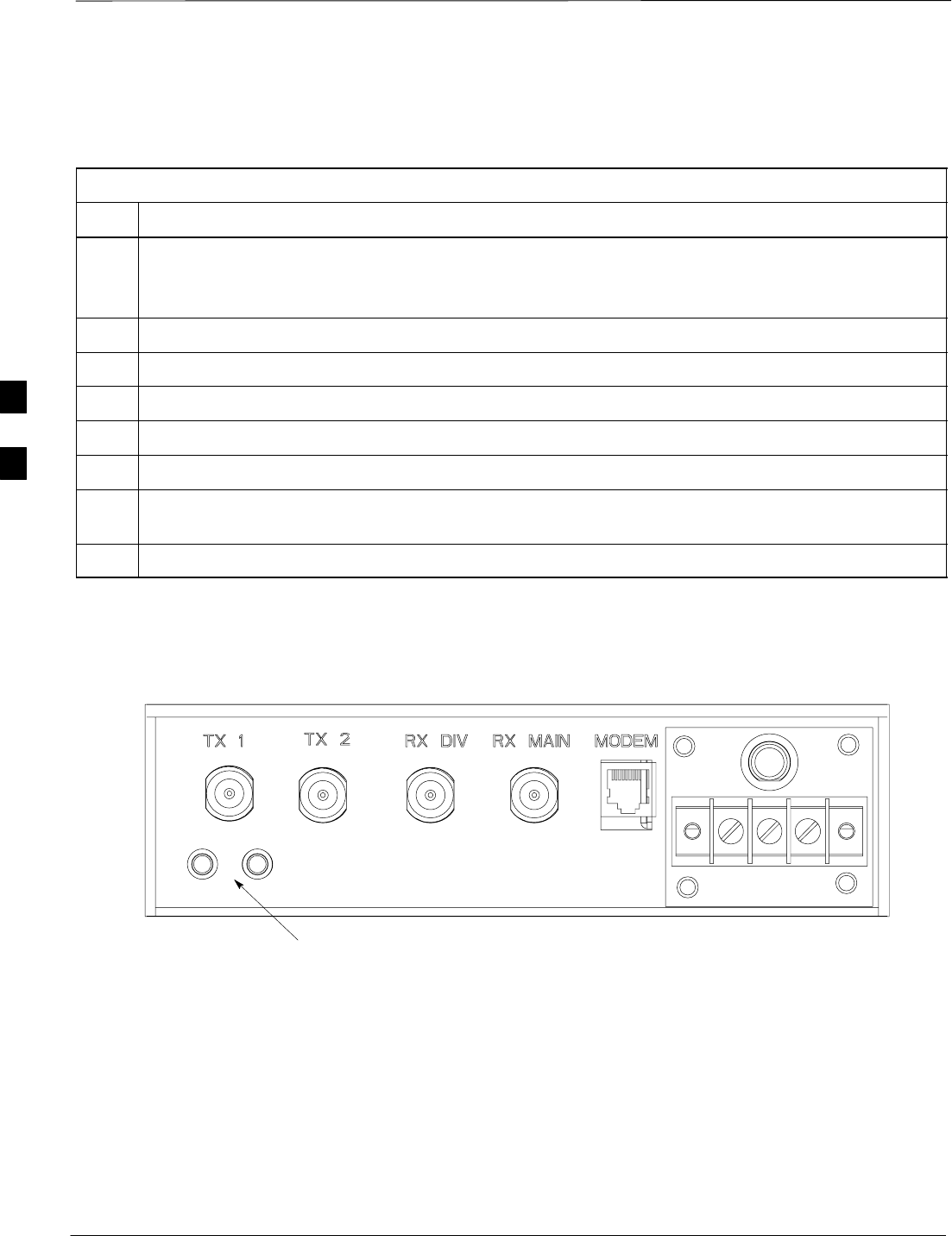
Earth Ground Cabling – continued
DRAFT
1X SC480 BTS Hardware Installation, Optimization/ATP, and FRU Jun 2004
4-48
BTS Ground Procedure
Follow the procedure in Table 4-24 to attach the ground cable.
Table 4-24: Procedure to Attach the Earth Ground Cable
Step Action
NOTE
Due to variability in rack placement, the rack is isolated from ground to reduce the chances of creating
ground loops.
1Retrieve ground lug and cabling.
1a Using a wire stripper, trim back 1/2–inch of the ground cable insulation from each end.
1b Using a crimp tool crimp the lug onto one end of the cable.
1c Attach the ground clamp to the opposite end of the ground cable.
2Using two screws attach the ground cable and lug to the BTS. See Figure 4-31.
3Slide ground clamp over ground anchor and secure using a lockwasher. Use a 13mm socket to tighten
the hex nut. Use a torque wrench to tighten hex nut to 5.0 N–M (44 in–lbs).
4Use tie–wraps as required to dress the ground cable, unless conduit is used.
GROUND LOCATION
Figure 4-30: Detail Location of Ground Studs
25A 25
4
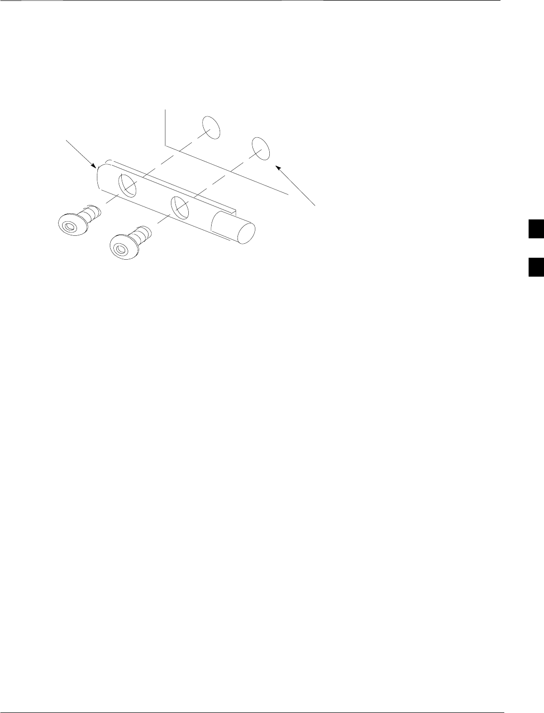
Earth Ground Cabling – continued
Jun 2004 4-49
1X SC480 BTS Hardware Installation, Optimization/ATP, and FRU
DRAFT
Figure 4-31: Grounding Location on BTS
GROUND SCREW
HOLES
P/O BTS RF Panel
GROUND LUG
M6 SCREWS
Outdoor Grounding
Considerations
cCLPA
The cCLPAs are designed to mount directly to the antenna tower. They
have primary lightning protection on all terminations. There is a ground
stud provided to connect the unit to the tower. If the cCLPAs are not
mounted on the tower, they should be mounted as close as possible to an
antenna ground system connection. All interconnect cables should be in
conduit or solid shield RF cables.
PDE
The Primary PDE is the master ground point for all the outdoor
equipment. This Primary PDE should be mounted within 2 meters of
the master ground connection of the antenna ground system. The
secondary PDE should be mounted within 1 meter of the primary PDE
and single point grounded to the same master ground point.
Compact BTS and TME
The Compact BTS and TME and all other outdoor expansion hardware
should be located within 5 meters of the primary PDE. They are all to
be single point grounded to the system master ground. All these
expansion enclosures are insulated from ground through their respective
mounting brackets. All interconnect cables should be in conduit or solid
shield RF cables. It is recommended that these cables be run in
raceways to reduce the loop dimensions of the cable runs. This
minimizes the effect of inducted currents caused by the intense
electromagnetic field of lightning current.
Antennas
The Compact BTS is being installed at an antenna site that has a proper
ground system for the antenna. Proper ground connection points are also
available for the cCLPA and PDE units.
4

Earth Ground Cabling – continued
DRAFT
1X SC480 BTS Hardware Installation, Optimization/ATP, and FRU Jun 2004
4-50
Site Requirements
The enclosures are mounted according to the site documentation. Refer
to Figure 2-10, Figure 2-13 through Figure 2-15 for dimensions and
clearances and spacing information.
Figure 4-32 shows an example of a mounted single system outdoor
grounding diagram. Figure 4-33 shows an example of a mounted
multiple unit system outdoor grounding diagram.
Outdoor Grounding Procedure
Follow the procedure in Table 4-25 to set up a site for grounding.
Table 4-25: Procedure to Ground an Outdoor Site
Step Action
1If not already known, consult site documentation for location to mount system.
2Verify that all master ground for the system is in place.
3Follow the procedures as described in Chapter 4 for installing the PDE, TME, and cCLPA.
4Once installation is complete, ground the Primary PDE to the system master ground.
5Route grounding cables from the other enclosures to the Primary PDE. Apply anti–oxidant grease to
ground lugs and connections.
* IMPORTANT
In order to route the TME to PDE Earth ground cable through the power conduit, a jumper cable must
be spliced from the conduit ground bushing to the earth cable.
6Ground the cCLPA to the system master ground. Apply anti–oxidant grease to ground lug and
connection.
7Ground the antennas to the system master ground.
8Once grounding is completed, layout conduit or solid shield RF (SSRF) cables.
9Route wires from PDE through conduit or route SSRF cables to the TME.
10 Route Data cabes from the TME to the cCLPAs.
11 Route AC power and battery backup (if used) to PDE.
12 Route DC power from PDE to cCLPA and TME.
13 Perform the procedures described in the remainder of this Chapter.
4
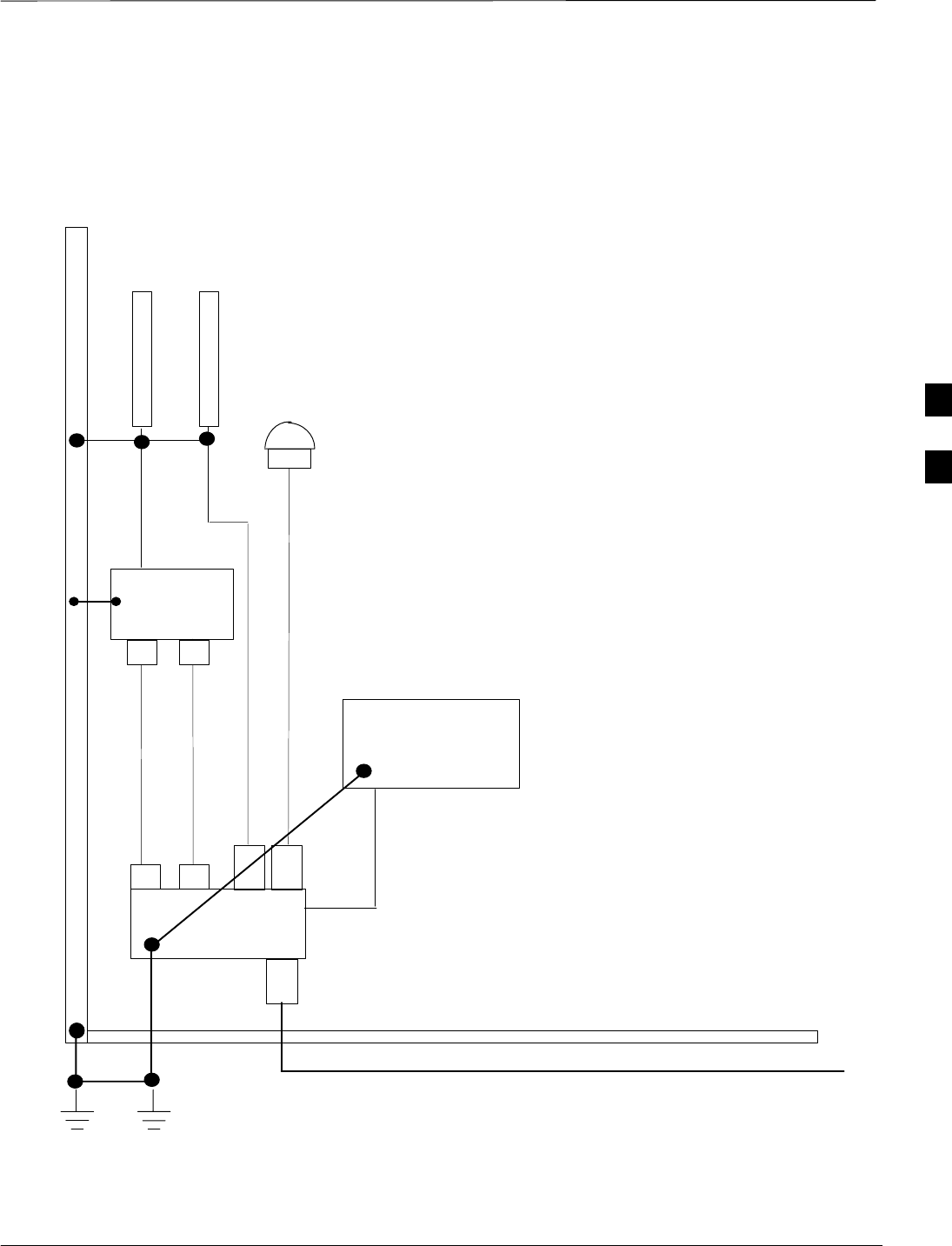
Earth Ground Cabling – continued
Jun 2004 4-51
1X SC480 BTS Hardware Installation, Optimization/ATP, and FRU
DRAFT
Figure 4-32: Typical Outdoor Grounding Configuration
LEGEND:
1. PSA – Primary Surge Arrestor
2. SSA – Secondary Surge Arrestor
3. CDT – Conduit
4. SLD – Shielded Cable
5. EGD – Earth Ground
6. TWR – Tower Ground
SLD
PDE
TME
GPS
cCLPA
ANTENNAS
ANTENNA
TOWER
PSA
PSA
PSA
SSA
CDT
POWER and DATA LINES
SINGLE POINT
MASTER GROUND
EGD
EGD
TWR
EGD
SLD
CDT
TWR
TME and PDE are electrically
isolated from ground.
In addition, there are shielded RF
cables connecting the TME and
PDE.
The TME to PDE Earth ground cable
can be routed through the power
conduit as long as a jumper cable is
spliced from the conduit ground
bushing to the earth cable
SSA
SSA
SSA
The SSAs are attached to the rear
flange of the PDE.
DC Power
4
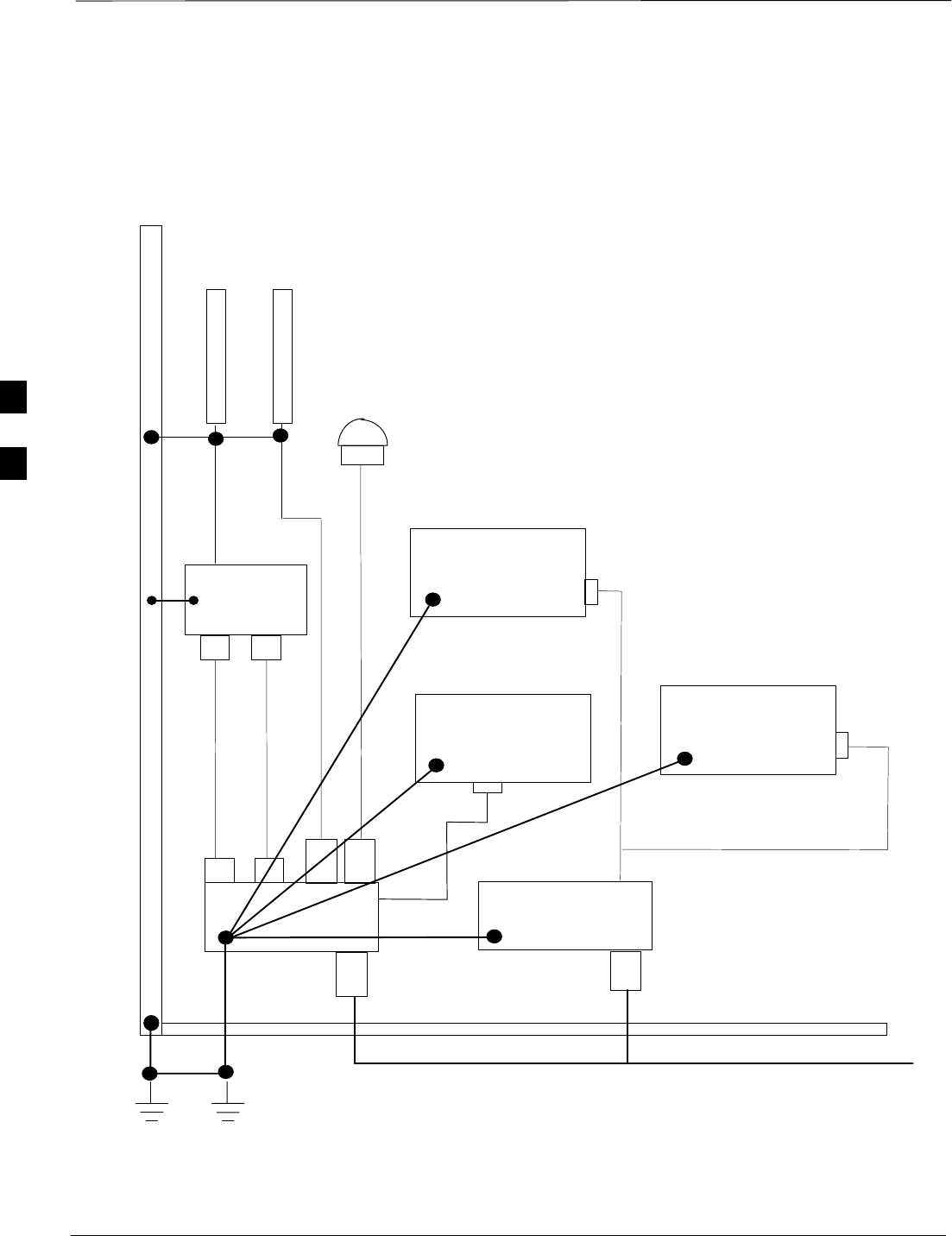
Earth Ground Cabling – continued
DRAFT
1X SC480 BTS Hardware Installation, Optimization/ATP, and FRU Jun 2004
4-52
Figure 4-33: Typical Multiple Outdoor Grounding Configuration
LEGEND:
1. PSA – Primary Surge Arrestor
2. SSA – Secondary Surge Arrestor
3. CDT – Conduit
4. SLD – Shielded Cable
5. EGD – Earth Ground
6. TWR –Tower Ground
7. TSA –Tertiary Surge Arrestor
SLD
PDE 1
TME 1
GPS
cCLPA
ANTENNAS
ANTENNA
TOWER
PSA
PSA
PSA
SSA CDT
POWER and DATA LINES
SINGLE POINT
MASTER GROUND
EGD
EGD
EGD
SLD
CDT
TWR
TWR
PDE 2
TME 2
TME 3
PSA
EGD
EGD
CDT
CDT
TSA
TSA
TSA
NOTE:
TME and PDE are electrically
isolated from ground.
In addition, there are shielded RF
cables connecting the TME and
PDE.
CDT
The TME to PDE Earth ground cable
can be routed through the power
conduit as long as a jumper cable is
spliced from the conduit ground
bushing to the earth cable
SSA SSA
SSA
The SSAs are attached to the rear
flange of the PDE.
DC Power
4
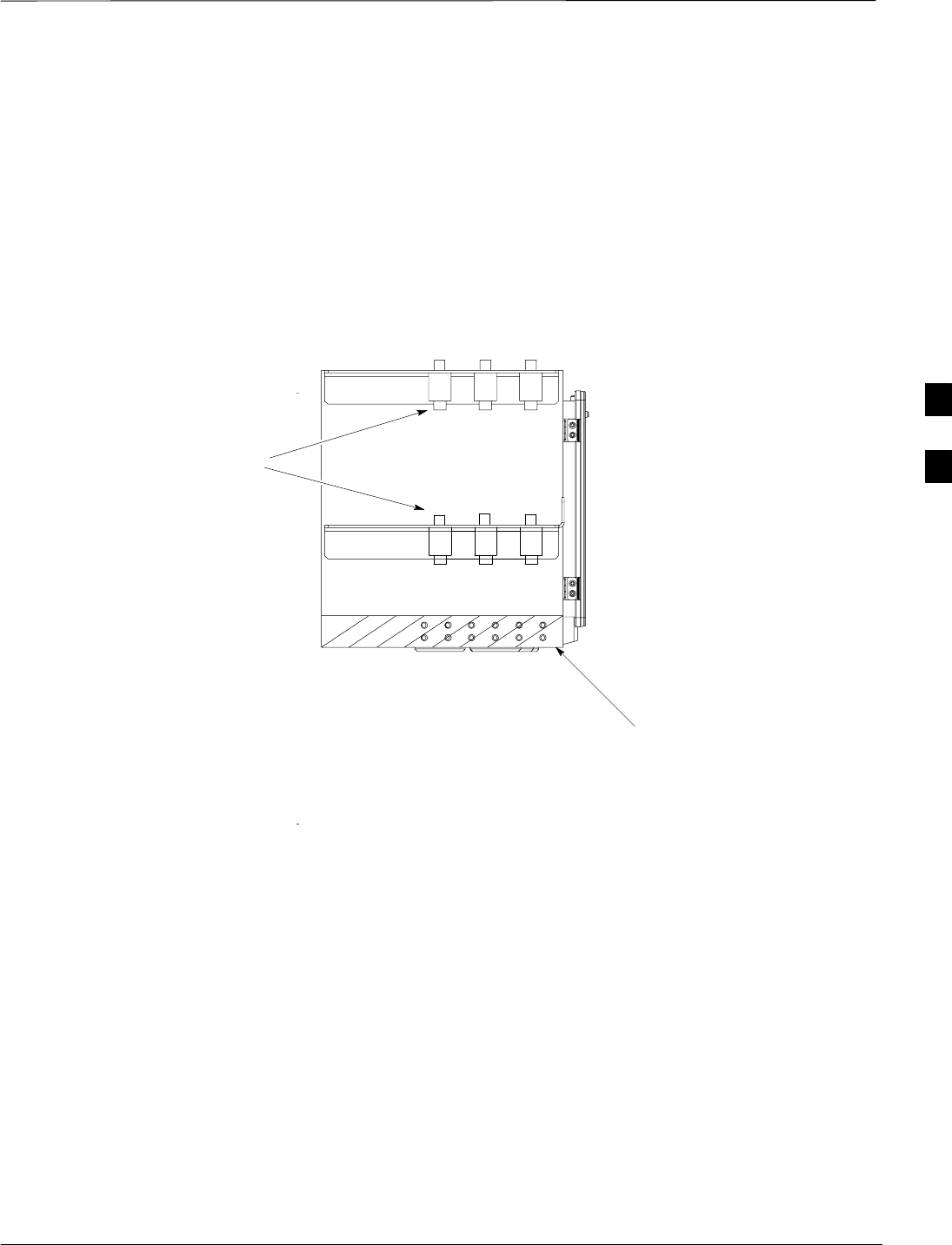
Earth Ground Cabling – continued
Jun 2004 4-53
1X SC480 BTS Hardware Installation, Optimization/ATP, and FRU
DRAFT
PDE Ground Connection
Figure 4-34 shows the ground location for the starter PDE and the other
outdoor enclosures.
Figure 4-34: Rear View of PDE
NOTE:
1. in a multiple unit setup,
all the grrounds are
connected to the rear
of the PDE (Starter).
2. Up to 10 surge
arrestors can be
attached to the rear
flange on the PDE.
GROUND Location
ti–cdma–wp–00356–v01–ildoc–ah
Surge Arrestors
4
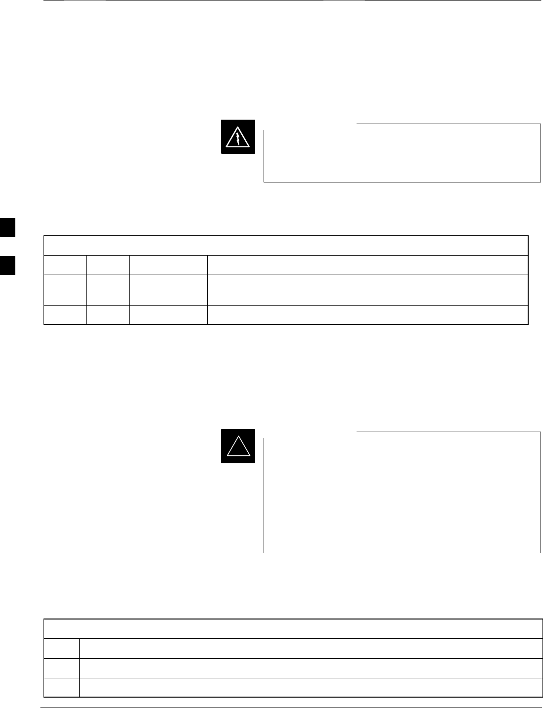
BTS DC Power Cabling
DRAFT
1X SC480 BTS Hardware Installation, Optimization/ATP, and FRU Jun 2004
4-54
Objective
The objective of this procedure is to attach the DC input cable to the
BTS for indoor configuration.
This equipment uses dangerous voltages and is capable of
causing death. Use extreme caution when handling and
testing this equipment.
WARNING
DC Cable Description
The following cable in Table 4-26 is necessary to do this procedure.
Table 4-26: DC Input Cable Description and Part Number
Cable Qty. Part Number Description
F 1 Customer
Supplied DC input cable with crimped lugs, 10 AWG, 10 m, designed to handle
+20 to +34 VDC power input.
1 7687717T02 Ferrite, Clip–on core
Power Cable and Connector
Signal Information
The DC input connector is located on the bottom, right side rear of the
BTS. The BTS is designed for –60 to –40 VDC.
The TME DC power connection is for outdoor configuration and only in
use if the Thermal Management Enclosure (TME) is used.
Motorola does not recommend the PDE be used to support
indoor configuration The PDE is not configurable for
indoor sites, and in general, it does not locate surge
protection functions appropriately for indoor cellsites.
For indoor, power and surge protection functions should be
implemented according to Standards and Guidelines for
Communication Sites using telecom–grade third party
equipment that is available through the ancillary group.
IMPORTANT
*
Procedure
Use the following procedure in Table 4-27 to connect the DC voltage
input cable to the BTS. Refer to Figure 4-35.
Table 4-27: Procedure to Connect DC Power to the BTS
Step Action
1Ensure that DC power source circuit breaker is disengaged (OFF).
2Route DC power cables to the rear of the BTS.
4
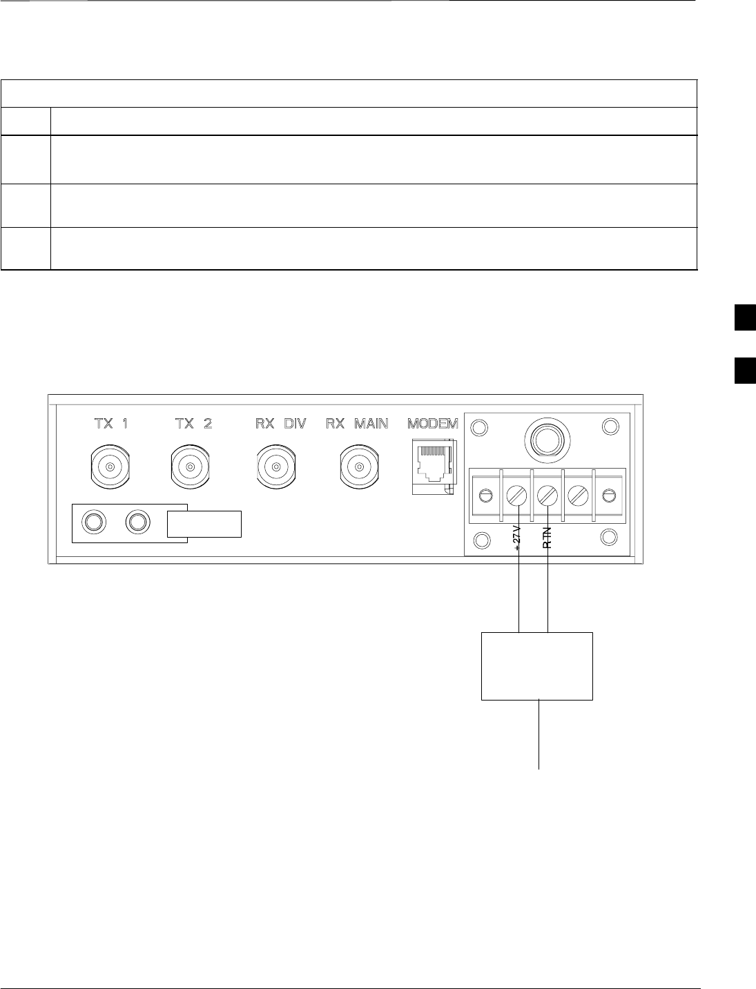
BTS DC Power Cabling – continued
Jun 2004 4-55
1X SC480 BTS Hardware Installation, Optimization/ATP, and FRU
DRAFT
Table 4-27: Procedure to Connect DC Power to the BTS
Step Action
3Connect the “–” wire (black) to the RTN terminal.
Connect the “+” wire (red) to the +27 V terminal.
4Bundle wires together and place ferrite core around wires. Ensure that the wires are not being pinched
before closing and latching the ferrite core.
5Slide ferrite core as close to the BTS connection as possible without causing stress. Use a tie–wrap on
the ferrite core side away from the connection. The tie–wrap holds the ferrite core in place.
Figure 4-35: DC Power Terminal Strip
NOTE:
1. The TME DC power connection is not
in use unless a TME is used.
2. A surge suppressor is recommended
between the BTS and the DC power
source.
TME
25A
SURGE
SUPPRESSOR
DC Power from
source
25
4
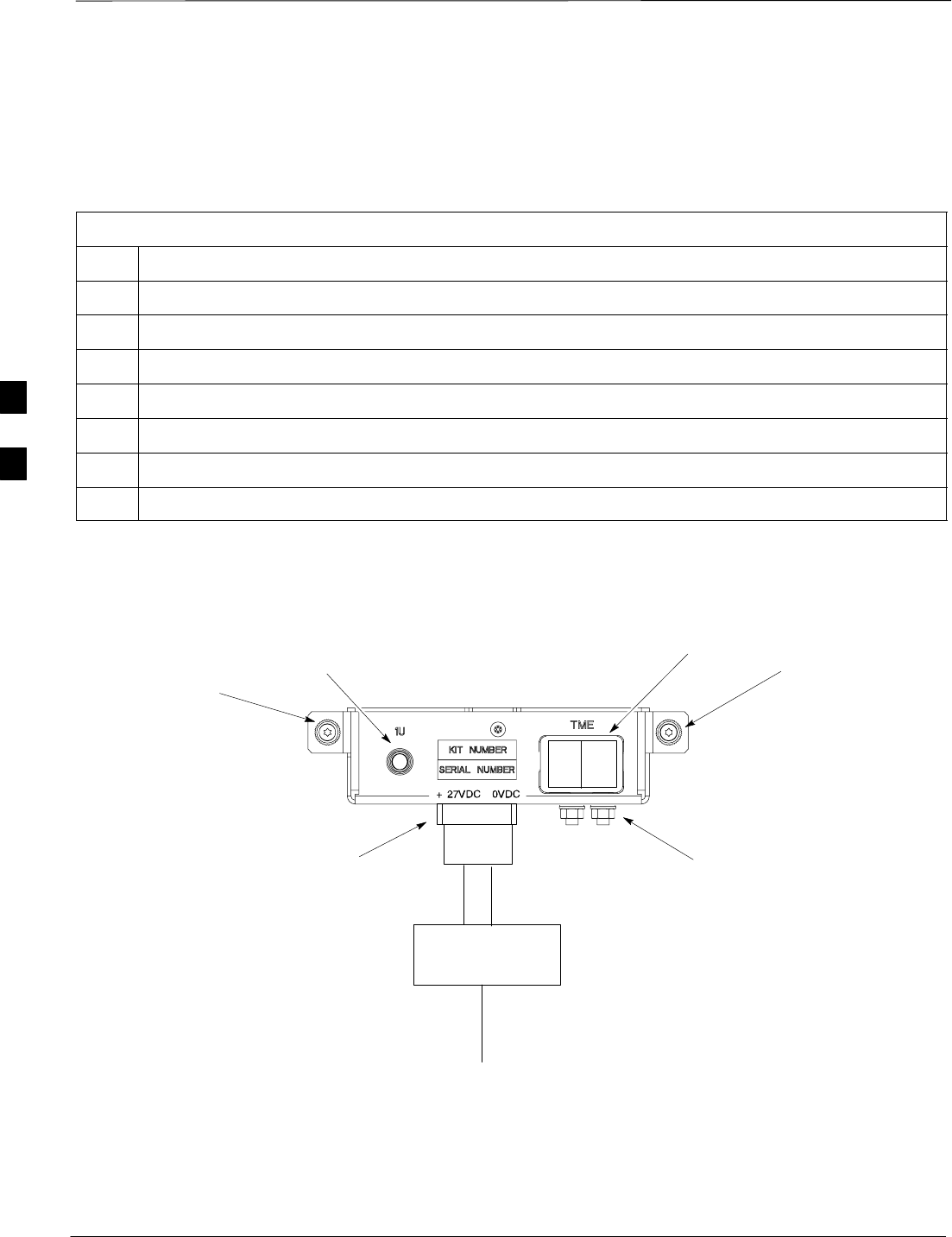
BTS DC Power Cabling (Indoor) – continued
DRAFT
1X SC480 BTS Hardware Installation, Optimization/ATP, and FRU Jun 2004
4-56
Connect DC Power to TME
Procedure
Use the following procedure in Table 4-28 to connect the DC voltage
input cable to the TME. Refer to Figure 4-36.
Table 4-28: Procedure to Connect DC Power to the BTS
Step Action
1Ensure that DC power from PDE is disengaged (ciruit breaker set to OFF).
2Route DC power cable through conduit to TME POWER Cable hole location.
3Ensure that 1U and TME circuit breakers are disengaged (pulled out).
4Remove protective cover from PDA DC power connector.
5If not already done, trim insulation back about 15 mm (1/2–in) on each wire.
6Insert the cable connector into the plug on the PDA. See Figure 4-36.
7Replace protective cover.
Captive
Screw
Captive
Screw
FRONT
ti–cdma–wp–00348–v01–ildoc–ah
Ground
Location
1U
Circuit
Breaker
TME Circuit
Breaker
(Rocker Style)
+27 VDC
Connector
Socket
Figure 4-36: TME Power Distribution Assembly for +27VDC
SURGE
SUPPRESSOR
DC Power from
source
4
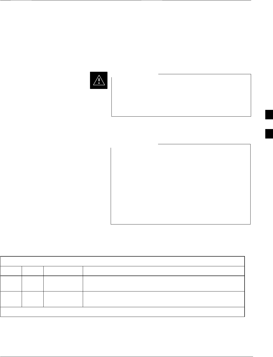
AC / DC Power Cabling Installation
Jun 2004 4-57
1X SC480 BTS Hardware Installation, Optimization/ATP, and FRU
DRAFT
Objective
The objective of this procedure is to install the AC power cabling and
Battery Backup input cables to the Power Distribution Enclosure (PDE).
This equipment uses dangerous voltages and is capable of
causing death. Use extreme caution when handling and
testing this equipment.
Earth connection is essential before connecting the power
due to the presence of high earth leakage current.
CAUTION
AC Cable Description
The Power Distribution Enclosure (PDE) is UL rated at 14
Amperes, in the range 200–240 VAC. The Customer Site
installation must provide a disconnect device and over
current protection device. A breaker size of 25 Amperes is
recommended or as appropriate by local electrical code.
The frame can accommodate an AC conductor range of 6
AWG to 12 AWG, as limited by the internal AC terminal
block. Cable sizing should be determined by Local
Electrical Codes, using 90C min rated conductors, with
derating for 50C operation. Motorola recommends not less
than 10AWG copper for buried/raceway cables.
NOTE
The cables listed in Table 4-29 are recommended for this installation.
However, consult the manufacturer’s installation guide for further
information.
Table 4-29: AC Input Cable Description and Part Number
Cable Qty. Part Number Description
K 1 Customer
Supplied AC power cable with crimped lugs, 10 AWG, copper, designed for
200 to 240 VAC @ 25 A.
{L 2–7 Customer
Supplied DC power cables, 10 AWG, stranded, designed for +20 to +34 VDC
power input
{ Length of cables are dependent upon BTS equipment site layout.
AC and DC Power Cabling
Procedure
After PDE is installed, connect the AC and DC power cables according
to the manufacturer’s installation specification.
4

AC / DC Power Cabling Installation (Outdoor) – continued
DRAFT
1X SC480 BTS Hardware Installation, Optimization/ATP, and FRU Jun 2004
4-58
Battery Backup Power Cabling
Procedure
After PDE is installed, connect the Battery Backup DC power cable to
the PDE according to the manufacturer’s installation specification.
PDE to TME and cCLPA DC
Power Cabling Procedure
After PDE is installed, connect the DC power cables from the TME and
cCLPA according to the manufacturer’s installation specification.
4

Antenna Cabling
Jun 2004 4-59
1X SC480 BTS Hardware Installation, Optimization/ATP, and FRU
DRAFT
Objective
The objective of this procedure is to install the cabling for the
antenna(s). This cabling is installed between the unit and the
customer–supplied lightning arrestor(s). If lightning arrestor(s) are not
required, the cabling connects directly to the antenna(s).
Cable Descriptions
The following cables in Table 4-30 are necessary to do this procedure.
Table 4-30: Cable Descriptions and Part Numbers
Cable Qty. Part Number Description
B 1–6* Andrew
LDF4–50
Customer
Supplied
RF Cable, 800 MHz, length selections: 10 m (31 ft.)
* Four antenna cables are required if one cCLPA is used. Six are required if two cCLPAs are used.
Procedure
Install the cabling between the BTS, external lightning arrestors, and the
cCLPA. If lightning arrestors are not present, the cables connect to the
antenna.
Cable the BTS as shown in Figure 4-37. Torque the connectors to 4.3
N–M (38 in–lbs).
Perform the procedure in Table 4-31 to install the antenna cables.
Table 4-31: Procedure to Install Antenna Cables
Step Action
1Check with site documentation to determine proper location for mounting antennas.
2If used, connect lightning arrestors. Surge arrestors are physically mounted to the rear flange of the
PDE.
3With cCLPA configuration, proceed to step 4.
Without cCLPA configuration, proceed to step 6.
4Route antenna cables to cCLPA and Compact BTS. See Figure 4-37 or Figure 4-38. Proceed to step 7.
5Route antenna cables between cCLPA and Compact BTS. See Figure 4-37 or Figure 4-38. Proceed to
step 7.
5a If a TME is used (outdoor configuration), route antenna cables to appropriate TME connectors.
6Route antenna cables to Compact BTS. See Figure 4-39. Proceed to step 7.
7Dress cables as necessary, unless conduit is used.
4
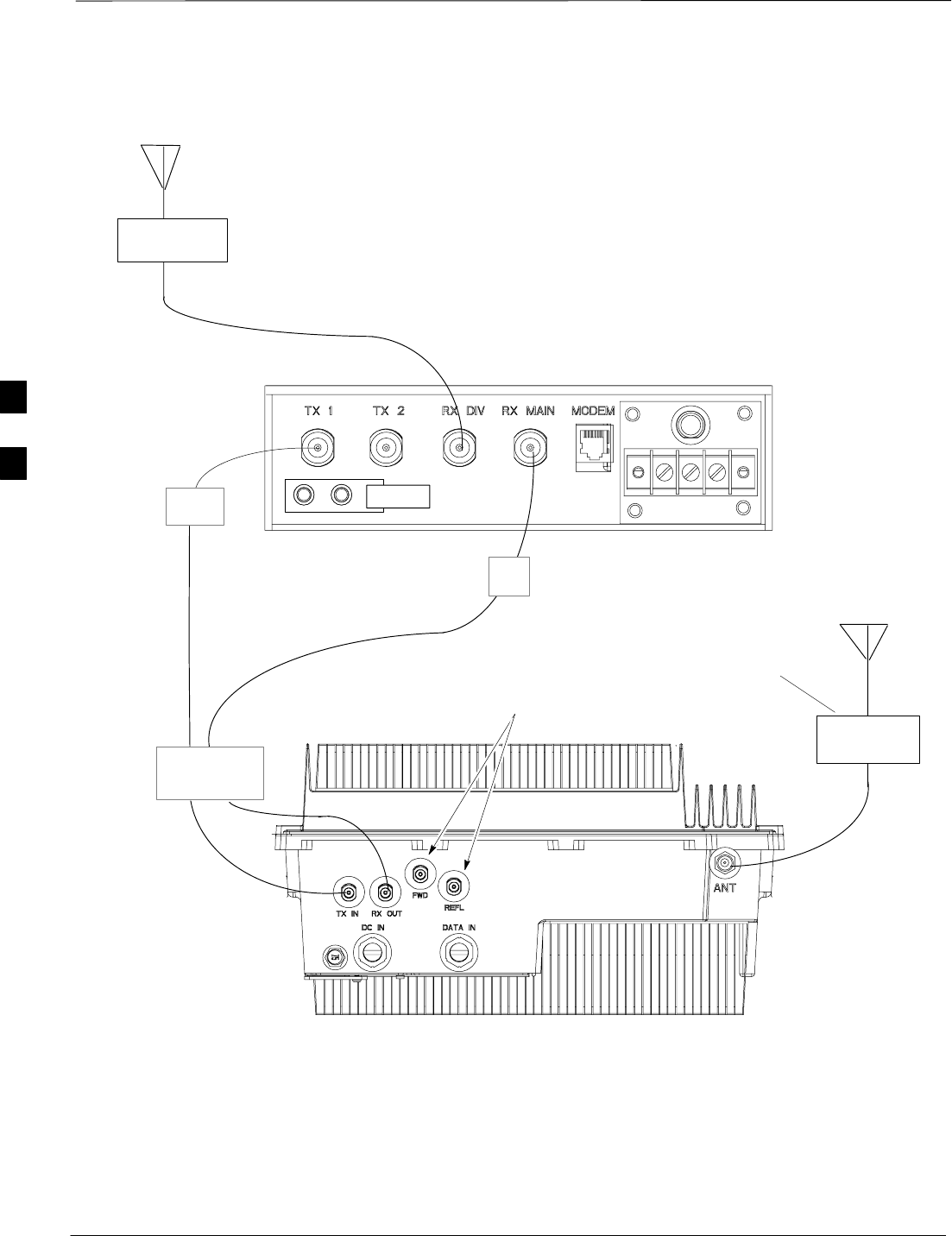
Antenna Cabling – continued
DRAFT
1X SC480 BTS Hardware Installation, Optimization/ATP, and FRU Jun 2004
4-60
LIGHTNING
ARRESTOR
Antenna A
(B)
Antenna B
50–Ohm
Loads
Figure 4-37: Antenna Cabling (With cCLPA)
(B)
(B)
(B)
NOTE:
If the antennas are located indoors the lightning arrestors
are not required.
If the antennas are located outdoor and the BTS indoor,
the arrrestors are required and located in the integrated
wall entry ground system panel
.
If this is an oudoor configuration then surge arrestors are
required on both ends of the TX1 and RX MAIN cables.
This LA is not required for
outdoor configuration.
LIGHTNING
ARRESTOR
SURGE
ARRESTORS
SA
SA
Surge Arrestors are required on both
ends of the antenna cables in an
outdoor configuration.
4
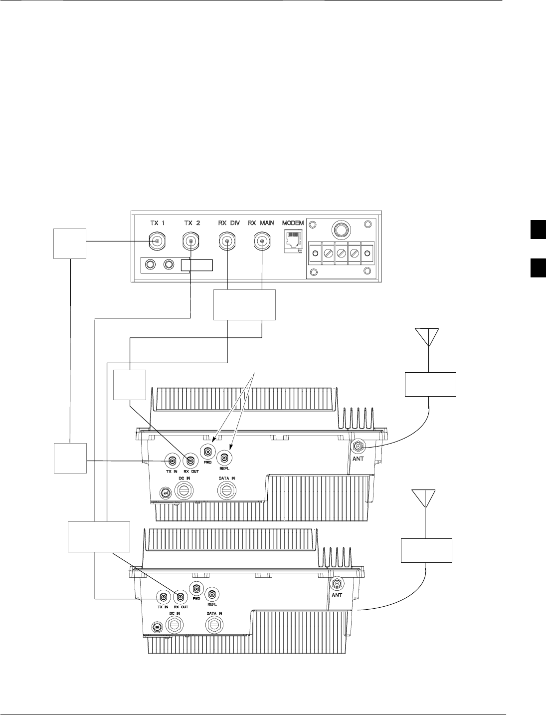
Antenna Cabling – continued
Jun 2004 4-61
1X SC480 BTS Hardware Installation, Optimization/ATP, and FRU
DRAFT
LIGHTNING
ARRESTOR
Antenna
A
(B)
50–Ohm
Loads
LIGHTNING
ARRESTOR
Antenna
B
(B)
cCLPA 1
cCLPA 2
(B)
(B)
(B)
(B)
Figure 4-38: Antenna Cabling with 2 cCLPAs
NOTE:
If the antennas are located indoors the lightning arrestors
are not required.
If the antennas are located outdoor and the BTS indoor,
the arrrestors are required and located in the integrated
wall entry ground system panel
.
If this is an oudoor configuration then surge arrestors are
required on both ends of the BTS to cCLPA TX and RX
cables.
These LAs are not
required for outdoor
configuration.
SURGE
ARRESTORS
SURGE
ARRESTORS
SA
SA
SA
Surge Arrestors are required on both
ends of the antenna cables in an
outdoor configuration.
4
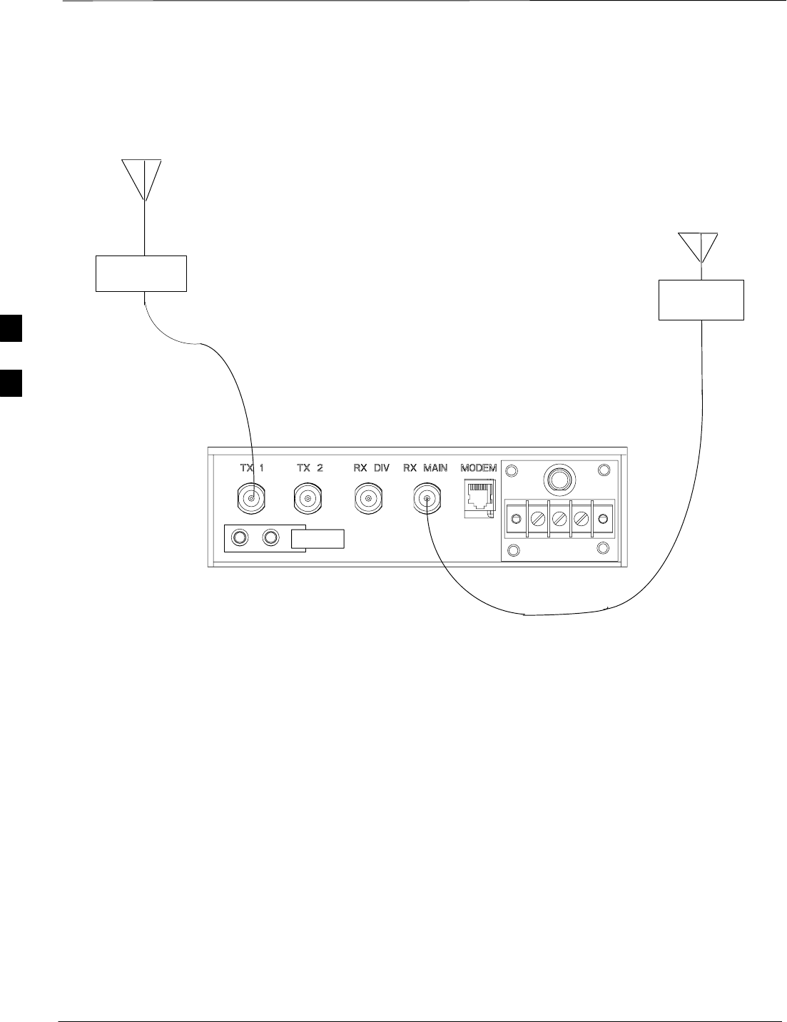
Antenna Cabling – continued
DRAFT
1X SC480 BTS Hardware Installation, Optimization/ATP, and FRU Jun 2004
4-62
LIGHTNING
ARRESTOR
Antenna A
(B)
LIGHTNING
ARRESTOR
Antenna B
(B)
Figure 4-39: Two Antenna Cabling (Without cCLPA)
NOTE:
If the antennas are located indoors the lightning arrestors
are not required.
If the antennas are located outdoor and the BTS indoor,
the arrrestors are required and located in the integrated
wall entry ground system panel.
If it is an outdoor configuration, then surge arrestors are
required on the antenna cables.
4
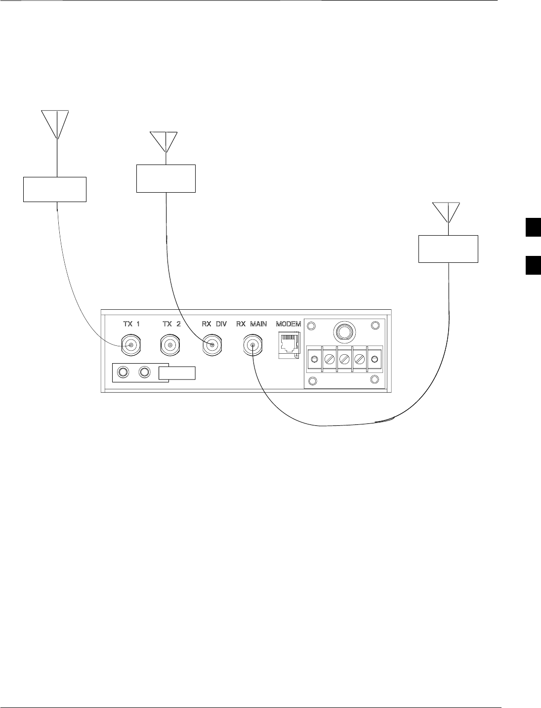
Antenna Cabling – continued
Jun 2004 4-63
1X SC480 BTS Hardware Installation, Optimization/ATP, and FRU
DRAFT
LIGHTNING
ARRESTOR
Antenna A
(B)
LIGHTNING
ARRESTOR
Antenna B
Figure 4-40: Three Antenna Cabling (Without cCLPA)
NOTE:
If the antennas are located indoors the lightning arrestors
are not required.
If the antennas are located outdoor and the BTS indoor,
the arrrestors are required and located in the integrated
wall entry ground system panel.
If it is an outdoor configuration, then surge arrestors are
required on the antenna cables.
LIGHTNING
ARRESTOR
Antenna C
(B) (B)
4

Span Line, RGPS, and RF GPS Cabling
DRAFT
1X SC480 BTS Hardware Installation, Optimization/ATP, and FRU Jun 2004
4-64
Objective
The objective of this procedure is to install the span line and RGPS
cabling.
Cable Labels
The cable designations are referenced to Table 3-1 in the “Cable
Description” area of this chapter.
Required Tools and Materials
Table 4-32 provides the quantities and descriptions of the cables.
Table 4-32: List of Required Cables
Cable Qty. Part Number Description
C 1 T472AA RGPS cable, 15 m (50 ft.)
T472AB RGPS cable, 38 m (125 ft.)
T472AC RGPS cable, 76 m (250 ft.)
T472AD RGPS cable, 152 m (500 ft.)
T472AE RGPS cable, 304 m (1000 ft.)
T472AF RGPS cable, 608 m (2000 ft.)
C1 1 T650AA Punchblock to CBIO Board, 15 pin D–connector on one end and
loose wires on the other end.
D 6 Customer Supplied Span cable, 4 or 8 conductors, 24–28 AWG stranded, twisted pair
J* 1 SGRG4030 RF–GPS Cable, 1/2–inch coaxial, length = 50 ft. Two male N–type
connectors, one end to be terminated after routing of cable
1–2** 7687717T02 Ferrite, clip–on core
* An SMA to N adapter is required; otherwise a cable must be made with an SMA connector on one end.
** Attach one ferrite bead per bundle of 3 (or less) span lines and one for RGPS cable. Ferrite core is not
required for RF–GPS cable.
Connecting the Span Line
Cable
The BTS provides for three 1X T1/E1 span lines and three MCC–Data
Only (MCC–DO) span lines (See Figure 4-41). Each interface is made
up of Transmit Tip/Ring and Receive Tip/Ring connections.
The Transmit and Receive data flow is given from the perspective of the
BTS.
4
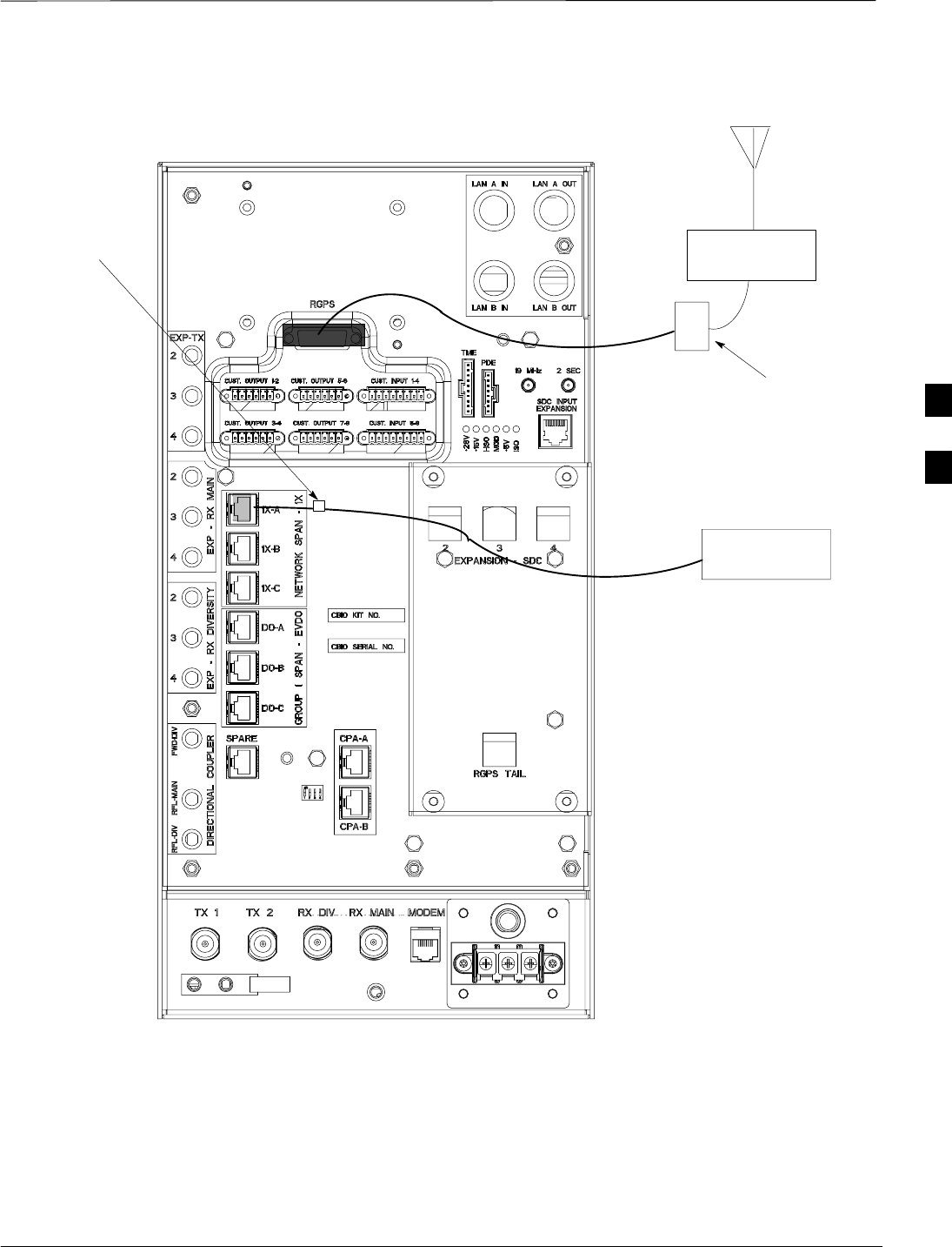
Span Line, RGPS, and RF–GPS Cabling – continued
Jun 2004 4-65
1X SC480 BTS Hardware Installation, Optimization/ATP, and FRU
DRAFT
D
C1
Ferrite
Beads
NOTE:
Ferrite Beads are used in
indoor configuration only.
Surge
Protected
Punchblock
(Customer
supplied)
C
LIGHTNING
ARRESTOR
LIGHTNING
ARRESTOR
ti–cdma–wp–00311–v01–ildoc–ah
Figure 4-41: Span and RGPS Cabling Details
4

Span Line, RGPS, and RF–GPS Cabling – continued
DRAFT
1X SC480 BTS Hardware Installation, Optimization/ATP, and FRU Jun 2004
4-66
Cable Pin and Signal
Information for Span Cabling
Table 4-33 gives the pin and signal information for the Span cable.
Table 4-33: Pin/Signal Information for Span Cable
BTS Interface Pin Wire/Stripe
Color Description
1 White/Orange RX RING
2 Orange RX TIP
3 White/Green NC
Span Line Cable
4 Blue TX RING
Span Line Cable
5 White/Blue TX TIP
6 Green NC
7 White/Brown NC
8 Brown NC
Span Cable Procedure
Follow the procedure in Table 4-34 to connect the span cable.
Table 4-34: Procedure to Install 1X or DO Span Cable
Step Action
1If BTS is configured for 1X operation, proceed to step 1a.
If BTS is confgiured for DO operation, proceed to step 1b.
1a Route 1X span line (Cable D) from site interface panel and connect to Network Span Group 1X
(1X–A) connector at the rear of the BTS.
1b Route DO span line (Cable D) from DO site interface panel and connect to Network Span Group 1 DO
(DO–A) connector at the rear of the BTS.
2If cable must be made, insert wires into RJ48 connector per Table 3-5.
3If more than one span cable is used, bundle them together and place ferrite core around cables. Ensure
that the cables are not being pinched before closing and latching the ferrite core.
4Slide ferrite core as close to the connectors as possible without causing stress. Use a tie–wrap on the
ferrite core side away from the connectors. The tie–wrap holds the ferrite core in place
5Secure cable to rack using tie–wraps, be sure to leave some slack.
4