Nokia Solutions and Networks T7GT1 2.5GHz DIVERSITY ACCESS POINT User Manual USERS MANUAL 2 OF 4
Nokia Solutions and Networks 2.5GHz DIVERSITY ACCESS POINT USERS MANUAL 2 OF 4
Contents
- 1. USERS MANUAL 1 OF 4
- 2. USERS MANUAL 2 OF 4
- 3. USERS MANUAL 3 OF 4
- 4. USERS MANUAL 4 OF 4
USERS MANUAL 2 OF 4
Access P oint Hardw are Installation Access P oint Equipment Identication
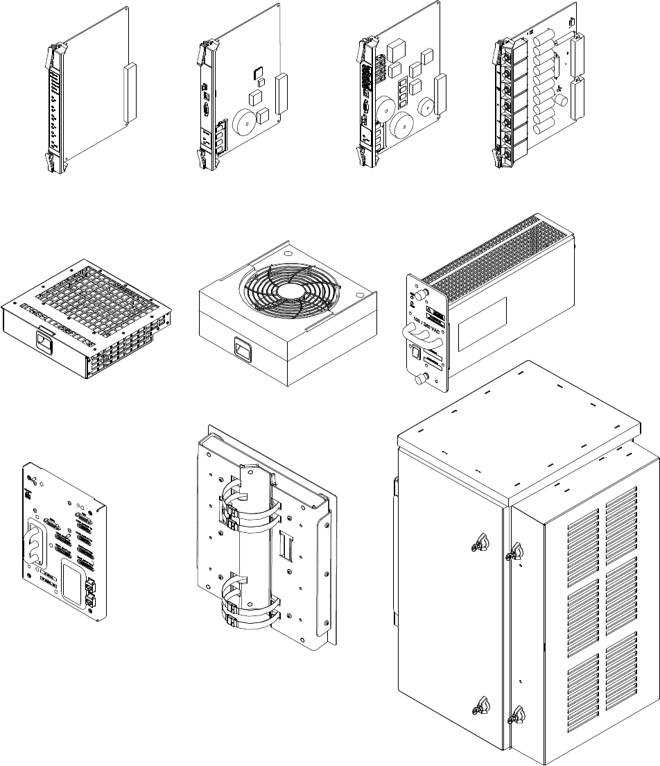
Figure 1 -3 BCU Hardw are
ti-cdma-04197.eps
Alarm Card
Fan Tray
BCU Chassis
I/O Panel
Pole Mount Bracket
Heater
Circuit Breaker CardModem Card CardController Card
PSU
68P09277A59 -5 1 -9
Draft OCT 2006
Access P oint Equipment Identication Chapter 1: Introduction
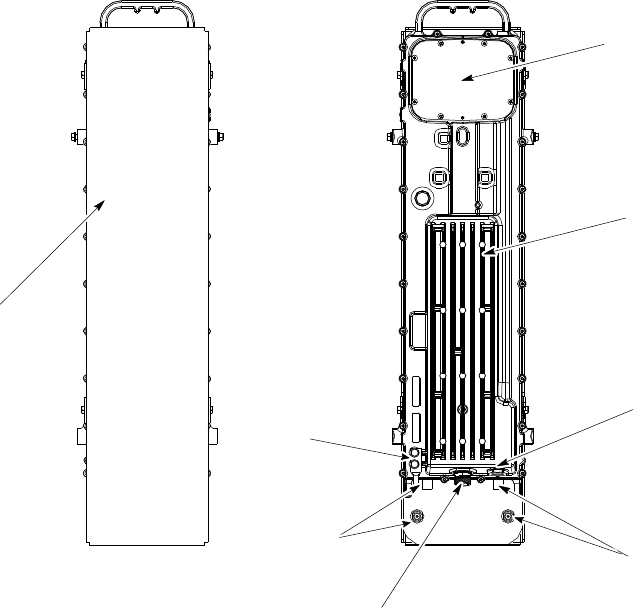
RF Head Hardware Identication
The Diversity Access P oint (DAP) RF Head Assembly consists of a two antenna element using a
single radome and a (one Transmit/Receive RF Module (RF Head)).
Figure 1 -4 DAP RF Head Hardw are
ti-cdma-04168.eps
RF Head
DC Power
Fiber Optic
RF Connector
Ground
Radome
RF Connector
Access
Panel
1 -10 68P09277A59 -5
Draft OCT 2006

C h a p t e r
2
Site Preparation
■■■■■■■■■■■■■■■■■■■■■■■■■■■■■■■■■■■■■■■■■■■■■■■■■■■■■■■■■■■■■■
■
■
■
■
68P09277A59 -5 2 -1
OCT 2006 Draft

Site Prepar ation Ov erview Chapter 2: Site Prepar ation
Site Preparation Overview■■■■■■■■■■■■■■■■■■■■■■■■■■■■■■■■■■■■■■■■■■■■■■■■■■■■■■■■■■■■■■
■
■
Overview
This chapter provides the procedures and information to verify that the site is ready for
equipment installation. It also provides procedures to ensure the safety of the installation
personnel, protect the equipment from damage, and verify the site layout parameters.
Ev ery effort should be made to pro vide a safe working en vironment for all installation
and service personnel.
Installation
This Base Control Unit (B CU) may be installed indoors or outdoors. The RF Head is installed
outdoors. The site preparation depends on the type of installation and the site characteristics.
Site Manager
The site manager is the person in charge of and responsible for the full site.
Verication and Procedures
V erifications typically have the installer check with the site manager that a condition has been
previously checked or procedure previously performed and meets a stated specification.
Inspections typically have the installer personally checking that a condition or item meets
stated specifications.
The verifications and procedures provided in this chapter are:
•Internal site inspections
•Preparing site for the arrival of equipment
•Site layout verification
2 -2 68P09277A59 -5
Draft OCT 2006

Access P oint Hardw are Installation Prepare Site for Equipment Arriv al
Prepare Site for Equipment Arrival■■■■■■■■■■■■■■■■■■■■■■■■■■■■■■■■■■■■■■■■■■■■■■■■■■■■■■■■■■■■■■
■
■
Description
This information covers various topics not all of which are needed at every site. Based on the
site characteristics execute the steps that apply to your site. Before installing the equipment, do
the following to ensure the safety of installation personnel and to protect the equipment.
Equipment Arrival
Before the equipment arrives, indicate to the transport company an area at the site where the
equipment can be unloaded and, if necessary , unpacked. The equipment should be carefully
delivered to the site, along with all equipment dollies and padding required to safely move the
equipment from the unloading area to the cell site. The following should also be provided,
outdoor weather protection, temporary lighting and power for lighting and power tools.
Procedure to Prepare the Site for the Equipment
Procedure 2 -1 Procedure to Prepare the Site for the B T S
1
Consult with site manager .
2
Locate the demarcation blocks for external utilities.
V erify that they are shown on the Site Engineering documents, and
determine the required cable routing back to the equipment frames.
3
V erify the following:
•AC power is available and meets the site documentation specifications
•P ole and/or wall mounting structures are adequate
•Outdoor cable runs are installed and meet local building codes
•Customer input termination tie points are available
•There is clear access to move the equipment to the desired mounting
area
•There is sufficient space for installation and service access to the
equipment
•Customer supplied shelters are installed
68P09277A59 -5 2 -3
Draft OCT 2006
Shipping and Handling Chapter 2: Site Prepar ation
Shipping and Handling■■■■■■■■■■■■■■■■■■■■■■■■■■■■■■■■■■■■■■■■■■■■■■■■■■■■■■■■■■■■■■
■
■
Overview
The purpose of this chapter is to describe how the Base Control Unit (B CU) and RF Head are
packaged for shipping and how to correctly unpack the units in preparation for installation.
How Equipment is Shipped
The B CU and RF Head will be shipped in separate containers or separate pallets. The
containers, if used will either be wood or card board, with packing material to protect the units.
If pallets are used, the units will be wrapped in packing material and strapped to the pallet.
Plastic wrapping will be used to encase the units and provide protection as well as securing the
units to the pallets.
The B CU is shipped with all cards/modules and internal cabling installed.
The RF Head is shipped fully assembled.
How Equipment Arrives
Before the equipment arrives, indicate to the transport company an area at the site where the
equipment can be unloaded and, if necessary , unpacked. The equipment should be carefully
delivered to the site, along with all equipment dollies and padding required to safely move the
equipment from the unloading area to the cell site. The site should also have the following items
available: outdoor weather protection and power for temporary lighting and power tools.
Unpacking
The unpacking process requires that the following procedures be completed in the order shown:
1. Unpack the shipping container
2. Inventory the shipping container
3. Inspect equipment for damage
Recommended Tools
The tools in T able 2 -1 are recommended to assist in opening the containers housing the
equipment. Tin snips Knife, box cutter , or scissors
2 -4 68P09277A59 -5
Draft OCT 2006

Access P oint Hardw are Installation Shipping and Handling
Table 2 -1 R ecommended Unpacking T ools
Qty
Description
1 Tin snips
1
Knife, box cutter , scissors
Unpacking Diagrams
The following diagrams show how to unpack the equipment.
Figure 2 -1 Shrink W r apped Shipment
Authors Note: Figure 2–1 will be new and Figure 2–2 will be changed.
68P09277A59 -5 2 -5
Draft OCT 2006
Shipping and Handling Chapter 2: Site Prepar ation
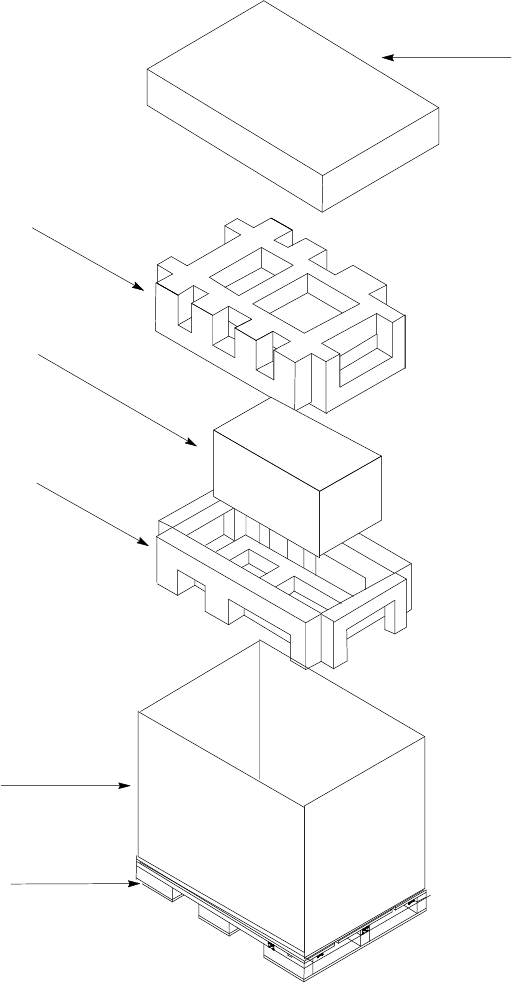
Figure 2 -2 Cardboard Shipping Container
ti-cdma-04170.eps
NOTE:
1. Normally this styrofoam
packing is attached to the
pallet. it is shown exploded
for clarity
2. This example shows the BCU
Styrofoam
Packing1
Cardboard
Box
BCU
Styrofoam
Packing
Cardboard Lid
Wood Pallet
2 -6 68P09277A59 -5
Draft OCT 2006

Access P oint Hardw are Installation Shipping and Handling
Unpacking a Cardboard Container or Shrink Wrapped Shipment
F ollow the procedure in Procedure 2 -2 to unpack equipment from a container or shrink wrap.
Procedure 2 -2 Unpacking Equipment from a Cardboard Container or Shrink W r ap
1
Inspect for damage.
Components may or may not be delivered on one pallet. Procedure
assumes components are delivered in separate containers on one
pallet.
2
If container is made of cardboard, proceed to step 3 .
3
Open container using tin snips to cut each outer steel band.
4
Cut bands securing pole mounting bracket container to top of B CU container .
Remove pole mounting bracket container , and place to one side.
5
Cut bands securing RF Head container and RF Head mounting bracket
container to pallet.
6
Cut bands securing RGPS container to pallet.
7
Proceed to Procedure 2-3 .
8
Using a knife or equivalent, carefully cut shrink wrap.
9
Carefully separate individual shipping containers.
Check for damage to containers.
10
Proceed to Procedure 2-3 .
Procedure 2 -3 Procedure to R emo v e Outdoor Equipment from Container
1
Lift cardboard container off of the B CU .
Find and remove equipment door key .
Open the shipping container holding the B CU mounting bracket.
Open the shipping container holding the RF Head.
Open shipping container holding RF Head mounting bracket assembly .
Open shipping container holding the GPS equipment.
2
Remove packing material from all containers.
3
Upon opening containers, if components are enclosed in plastic, use a knife
or equivalent to carefully cut plastic away .
Continued
68P09277A59 -5 2 -7
Draft OCT 2006

Shipping and Handling Chapter 2: Site Prepar ation
Procedure 2 -3 Procedure to R emo v e Outdoor Equipment from Container (Continued)
4
The B CU weighs a maximum of 68 kg (150 lbs). Recommend that
a minimum of two people be present to move the B CU .
Locate B CU door key . Remove B CU .
5
Use the key to open the door . V erify that cards and modules are installed.
6
If B CU is to be pole mounted, check that B CU has part of the mounting
bracket already attached. Remove B CU pole mounting bracket assembly
from its container .
7
The RF Head for the Diversity Access P oint (DAP) weighs 15.9
kg (35.0 lbs).
Remove the DAP RF Head from its container .
8
Remove DAP RF Head mounting bracket assembly from its container .
9
Remove GPS equipment from its container .
10
T ake inventory of equipment received.
Report the extent of any equipment damage to the
transport company and to appropriate management personnel.
2 -8 68P09277A59 -5
Draft OCT 2006

C h a p t e r
3
Cable Descriptions
■■■■■■■■■■■■■■■■■■■■■■■■■■■■■■■■■■■■■■■■■■■■■■■■■■■■■■■■■■■■■■
■
■
■
■
68P09277A59 -5 3 -1
OCT 2006 Draft