Nokia Solutions and Networks T7GT1 2.5GHz DIVERSITY ACCESS POINT User Manual USERS MANUAL 4 OF 4
Nokia Solutions and Networks 2.5GHz DIVERSITY ACCESS POINT USERS MANUAL 4 OF 4
Contents
- 1. USERS MANUAL 1 OF 4
- 2. USERS MANUAL 2 OF 4
- 3. USERS MANUAL 3 OF 4
- 4. USERS MANUAL 4 OF 4
USERS MANUAL 4 OF 4
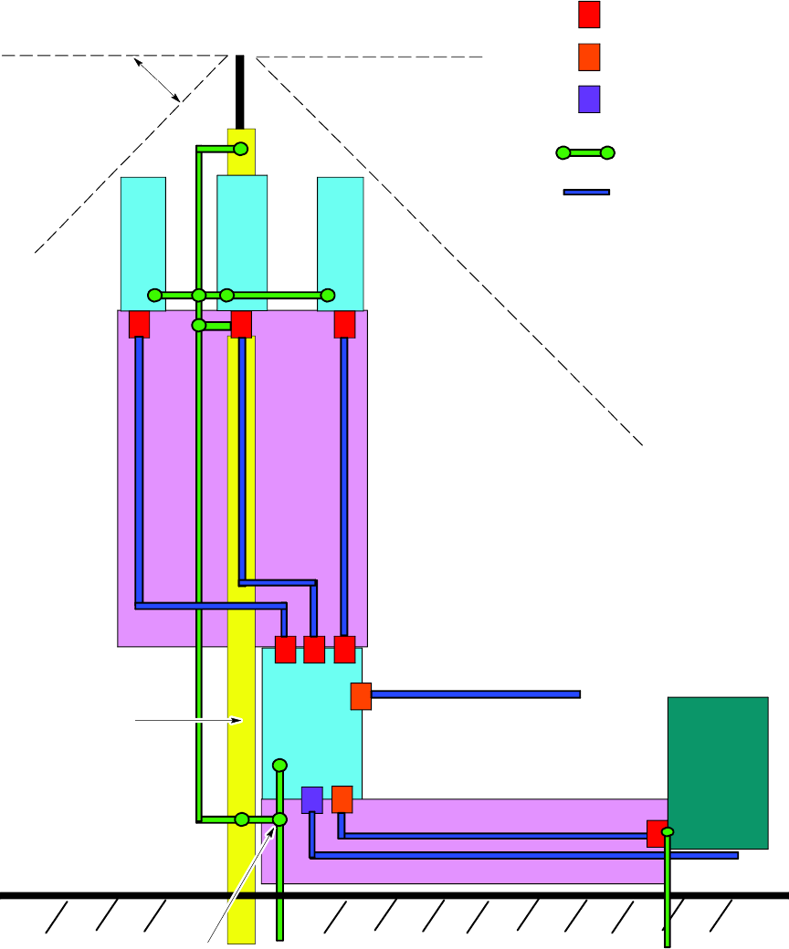
Access P oint Hardw are Installation Ground Cabling Installation
RGPS Grounding
Figure 4 -6 T ypical Outdoor Grounding Diagr am
ti-cdma-04180.eps
DC Primary Surge Arrestors
Backhaul & Customer I/O
Surge Arrestor
AC Primary Surge Protector
Bonded Ground / Earth
Connection
Conduit or
Shielded Cable
LPZ1
LPZ2 Secondary Protected Zone
LPZ0A
LPZ0B
Antenna Tower
45 Degree
IEC Recommended
Direct Strike
Protection Angle
RF
1
RF
2RF
3
BCU
BACKHAUL
CSU
AC Input
Backhaul
MASTER SINGLE
POINT EQUIPMENT
GROUND
LPZ0A-- Possible direct strike zone
LPZ0B-- No direct strike, but
unattenuated electromagnetic field
present
LPZ1 Primary Protected Zone
LPZ1
LPZ2
LPZ
2
LPZ
2
LPZ
2
Customer I/O
68P09277A59 -5 4 -21
Draft OCT 2006
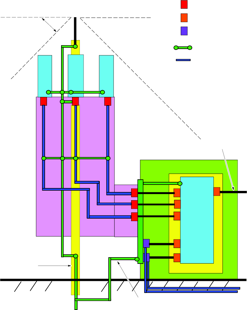
Ground Cabling Installation Chapter 4: Access P oint Hardw are Installation
Figure 4 -7 T ypical Indoor Grounding Diagr am
ti-cdma-04181.eps
DCPrimary Surge Arrestors
Secondary Surge Arrestor
AC & Backhaul Primary
Surge Arrestor
Bonded Ground / Earth
Connection
Conduit or
Shielded Cable
LPZ1
LPZ2 Secondary Protected Zone
LPZ0A
LPZ0B
Antenna Tower
45 Degree
IEC Recommended
Direct Strike
Protection Angle
RF
1
RF
2RF
3
BCU
INSULATOR
Customer I/O
MASTER SINGLE
POINT STRUCTURE
GROUND
LPZ0A-- Possible direct strike zone
LPZ0B-- No direct strike, but
unattenuated electromagnetic field
present
LPZ1 Primary Protected Zone
LPZ2
LPZ
2
LPZ
2
LPZ
2
Single Point
Ground
AC Input
Backhaul
STRUCTURE
4 -22 68P09277A59 -5
Draft OCT 2006

Access P oint Hardw are Installation AC P ower Cabling Installation
AC Power Cabling Installation■■■■■■■■■■■■■■■■■■■■■■■■■■■■■■■■■■■■■■■■■■■■■■■■■■■■■■■■■■■■■■
■
■
Objective
This section contains the procedure for installing the AC power cable.
This equipment uses dangerous v oltages and is capable of causing death. Use extreme
caution when handling and testing this equipment. Earth connection is essential before
connecting the power due to the presence of high earth leakage current.
AC Cable Description
Cable E as listed in T able 3 -1 is required for this installation.
The minimum bend radius for this cable is 90 mm.
Tools Required
The following tools are required to install the AC power cables.
•No . 2 Blade screw driver
AC Power Connection Procedure
F ollow the steps in Procedure 4 -4 to connect a 100/240 V AC (88–300 Vrms) Single Phase AC
power cable to the Base Control Unit (B CU). The AC power cable will be routed through one and
one -half inch conduit to the appropriate access hole on the underside of the B CU .
Continued
68P09277A59 -5 4 -23
Draft OCT 2006
AC P ower Cabling Installation Chapter 4: Access P oint Hardw are Installation
Procedure 4 -4 Procedure to Install AC P ower Cable
1
Ensure that AC power at the source is disabled before handling cable.
2
If not already done, route AC power cables through conduit to B CU Customer
Interface compartment.
3
In the B CU Customer Interface compartment, open the AC power cover , by
loosening two captive screws. AC P ower cover is hinged.
4
Loosen screws on AC power circuit breaker terminal block. Insert
AC power cables into LINE and NEUTRAL and tighten screws.
Ensure a good connection.
5
Close AC power cover and secure by tightening two captive screws.
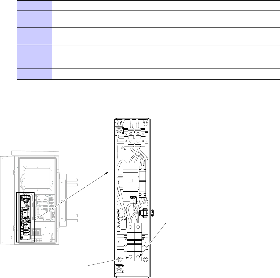
Figure 4 -8 BCU AC P ower Connection
ti-cdma-04182.eps
Neutral Connection
Line Connection
4 -24 68P09277A59 -5
Draft OCT 2006

Access P oint Hardw are Installation RF Head DC P ower Cabling Installation
RF Head DC Power Cabling Installation■■■■■■■■■■■■■■■■■■■■■■■■■■■■■■■■■■■■■■■■■■■■■■■■■■■■■■■■■■■■■■
■
■
Objective
This section contains the procedure for installing the RF Head DC power cables.
DC Cable Description
Cable G listed in T able 3 -1 is required for installation
Tools Required
The following tools are required to install the DC P ower cables.
DC Power Cable Installation
F ollow the steps in Procedure 4 -5 to install the DC P ower Cables.
Procedure 4 -5 Procedure to Install DC P ower Cables
1
If not already open, open the B CU Customer Interface compartment.
2
Before routing DC power cable, verify that it is properly color coded. If more
than one RF Head in use, ensure that they are all properly color coded.
Color coded labels and tie-wraps can be found on the
compartment side of the door of the B CU Customer Interface
compartment.Tie-wraps should be attached near the connnector .
3
Connect the DC power cables to connector RFU1 — RFU4, as required.
4
Route the DC P ower cables through conduit up to the tower . Bundle and
secure the cables (if RF Head is not present) or connect to the appropriate
RF Head.
68P09277A59 -5 4 -25
Draft OCT 2006
RF Head DC P ower Cabling Installation Chapter 4: Access P oint Hardw are Installation
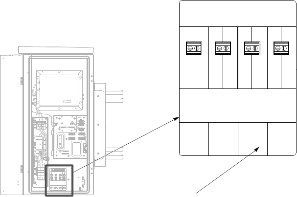
Figure 4 -9 Base Control Unit DC P ower Connection
ti-cdma-04183.eps
RFU 1, RFU 2, RFU 3, RFU4
CAUTION LIVE TERMINALS
CAUTION PRIOR TO INSTALLATION/REMOVAL OF WIRE TO TERMINAL
BLOCK. ASSOCIATED CIRCUIT BREAKER TO BE DISENGAGED
+54VDC
RETURN
+54VDC
RETURN
+54VDC
RETURN
+54VDC
RETURN
RFU 1 RFU 3 RFU 4RFU 2
4 -26 68P09277A59 -5
Draft OCT 2006
Access P oint Hardw are Installation Antenna Cabling Installation
Antenna Cabling Installation■■■■■■■■■■■■■■■■■■■■■■■■■■■■■■■■■■■■■■■■■■■■■■■■■■■■■■■■■■■■■■
■
■
Objective
This section contains the procedure for installing the antenna cables.
Installing Antenna Cables
The antenna cables will already be installed between the antenna and the RF Head.
68P09277A59 -5 4 -27
Draft OCT 2006
RGPS Cabling Installation Chapter 4: Access P oint Hardw are Installation
RGPS Cabling Installation■■■■■■■■■■■■■■■■■■■■■■■■■■■■■■■■■■■■■■■■■■■■■■■■■■■■■■■■■■■■■■
■
■
Objective
This section contains procedures for installing the Remote Global P ositioning System (RGPS).
Cable Description
Cables C and C1 as listed in T able 3 -1 are required for installation.
Tools Required
Cable Pinout
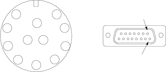
Figure 4 -10 Connector Pins Numbering for Cables C and C1
ti-cdma-04196.eps
1
2
3
4
5
6
7
8
9
10
11 12
CONNECTOR FOR CABLE C
PIN 1
CONNECTOR FOR CABLE C1
PIN 9
4 -28 68P09277A59 -5
Draft OCT 2006
Access P oint Hardw are Installation RGPS Cabling Installation
Table 4 -4 Pinout for Cables C and C1
Cable C Cable C1
Pin No.
Signal Name W ire Color
Connector A
Pin No.
Signal Name
Connector B
Pin No.
9
DC Ground 1 Blue–Black
15 RGPS Return 15
1 P ower 1
Blue
8
RGPS +54V Supply
8
8
DC Ground 2 Y ellow–Black
14 RGPS Return 14
10 P ower 2
Y ellow
7
RGPS +54V Supply
7
4
Transmit P ort (–) Green–Black
9
DA T A (-) From Head
12
5
Transmit P ort (+)
Green 1
DA T A (+) From Head
4
2
Receive P ort (–) White–Black
12
DA T A (-) T o Head
9
3
Receive P ort (+) White
4
DA T A (+) T o Head
1
7
No Connect
Red–Black
No Connect No Connect No Connect
6 No Connect
Red
No Connect No Connect No Connect
12
PPS Timing (–) Brown–Black
10
SYNC (-) From Head
10
11
PPS Timing (+)
Brown
2
SYNC (+) From Head
2
RGPS Installation
Figure 4 -11 shows the RF GPS Head and Figure 4 -12 shows the RGPS installation. Be sure to
factor in mounting considerations as described in Chapter 3 Cable Descriptions .
The RGPS head must not mak e contact with an y metal surface other than the pro vided
hardw are. Use only the equipment pro vided to mount the RGPS head. F ailure to do so
could damage the RGPS head.
Procedure 4 -6 Procedure for Installing the RGPS Head and Cabling
1
Determine the RGPS mounting location.
2
The structure of the w all should be v eried b y a qualied structur al
engineer .
Continued
68P09277A59 -5 4 -29
Draft OCT 2006
RGPS Cabling Installation Chapter 4: Access P oint Hardw are Installation
Procedure 4 -6 Procedure for Installing the RGPS Head and Cabling (Continued)
Mounting the RGPS head and hardware to an inadequate wall structure and/or
using inadequate installment methods can result in serious personal injury .
Use the appropriate mounting bolts for the mounting surface and install the
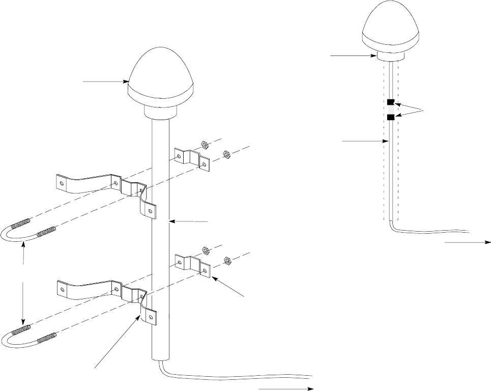
two wall mounting brackets. Refer to Figure 4-12 .
3
Route the 12-pin Deutsch connector of the RGPS cable (C) through the RGPS
mounting pipe.
4
Connect the RGPS cable (C) connector to the RGPS head 12-pin connector
as shown in Figure 4-12 and Figure 4-13 . Tighten the spinning flange on the
connector a quarter turn to secure the connection.
5
Insert the RGPS mounting pipe into the threaded mount of the RGPS head
and carefully hand-tighten.
6
Install the RGPS mounting pipe into the mounting brackets as shown in
Figure 4-12 . Tighten the U -bolt clamps to secure the assembly .
7
Route the free ends of the BTS RGPS cable (C1) and RGPS cable (C)
to the lightning arrestor . Remove any excess cable length and strip off
approximately 15 cm of the cables outer insulation.
8
Connect the 12 individual connectors and cable drain of each cable end to
the lightning arrestor as shown in Figure 4-14 . Double check the lightning
arrestor connections for compliance with those presented in Figure 4-14 .
9
Route the RGPS cable from the lightning arrestor to the bottom of the B CU .
10
If not already open, open the Customer Interface compartment.
If not already done, remove access hole cover .
1 1
Route the RGPS cable up through the access hole and conect to RGPS
D -Connector .
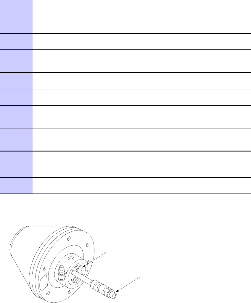
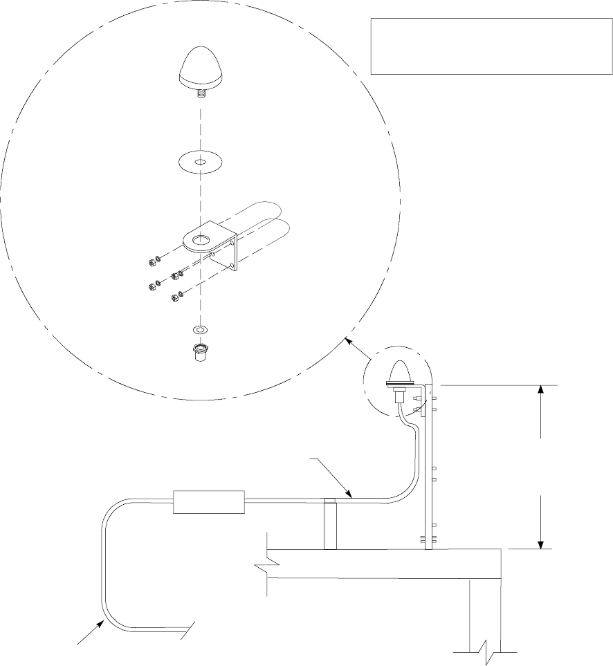
Figure 4 -11 RGPS Head
ti-cdma-04187.eps
THREADED MOUNT ADAPTER
12--PIN DEUTSCH TYPE MMP
CONNECTOR
4 -30 68P09277A59 -5
Draft OCT 2006
Access P oint Hardw are Installation RGPS Cabling Installation
Figure 4 -12 Installing the R emote GPS Head
ti-cdma-04188.eps
WALL MOUNTING
BRACKETS (2)
CLAMP BRACKETS (2)
U--BOLTS
CABLE TO LIGHTNING
ARRESTOR (CABLE C)
REFER TO VIEW A
RGPS HEAD WITH
12 PIN MALE
CONNECTOR
MATING
CONNECTORS
RGPS INTERFACE
CABLE WITH 12 PIN
FEMALE CONNECTOR
ON ONE END AND
UNTERMINATED WIRE
ON OTHER END
VIEW A
RGPS HEAD
(MOTOROLA PART
NUMBER 0186012H04)1
CABLE TO LIGHTNING
ARRESTOR (CABLE C)
Connecting the RGPS Cable to Lightning Arrestor
Figure 4 -13 is a diagram of the RGPS connections. Figure 4 -14 is a detail of the Lightning
Arrestor connections.
68P09277A59 -5 4 -31
Draft OCT 2006
RGPS Cabling Installation Chapter 4: Access P oint Hardw are Installation
Figure 4 -13 RGPS to Base Control Unit Connection Diagr am
ti-cdma-04189.eps
Blue/Black
Blue
Yellow/Black
Yellow
Green/Black
Green
White/Black
White
Red/Black
Red Brown/Black
Brown
1
2
3
45
6
7
8
9
1 0
1 1 12
Earth Ground
RGPS CABLE CONNECTOR
(VIEWED FROM CABLE PERSPECTIVE)
C
CABLE DRAIN
LIGHTNING ARRESTOR
(WNP CGDSO971017AA1
OR EQUIVALENT)
D--CONNECTOR
TO BCU
CELL SITE
GROUND =
C1
UNUSED 1
14
10
2
4
12
7
8
15
9
RGPS HEAD (MOTOROLA
P/N 0186012H04)
4 -32 68P09277A59 -5
Draft OCT 2006
Access P oint Hardw are Installation RGPS Cabling Installation
Figure 4 -14 RGPS Lightning Arrestor Wiring
ti-cdma-04190.eps
Blue/Black
Blue
Yellow/Black
Yellow
Green/Black
Green
White/Black
White
Red/Black
Red
Brown/Black
Brown
Cable Drain
Blue/Black
Blue
Yellow/Black
Yellow
Green/Black
Green
White/Black
White
Red/Black
Red
Brown/Black
Brown
Cable Drain
+40VDC Lines +17VDC Lines +17V DC Lines
+17VDC Equipm e nt+17VDC Equipment+ 40VDC E quipm e nt
C1 (RGPS)
TO BCU
UNIT
C (RGPS)
TO RGPS
RECEIVER
EARTH GROUND
MOUNTING PLATE
Blue/Black
Blue
Yellow/Black
Yellow
Green/Black
Green
White/Black
White
Red/Black
Red
Brown/Black
Brown
1
2
3
4
5
6
7
8
9
10
11
12
68P09277A59 -5 4 -33
Draft OCT 2006

RF GPS Cabling Installation Chapter 4: Access P oint Hardw are Installation
RF GPS Cabling Installation■■■■■■■■■■■■■■■■■■■■■■■■■■■■■■■■■■■■■■■■■■■■■■■■■■■■■■■■■■■■■■
■
■
Objective
The objective of this procedure is to install the Local (RF) Global P ositioning System (RF GPS)
cabling.
Tools and Materials
provides the quantities and descriptions of the cables.
•5/16 Breakaway T orque W rench 9 -in. lb
•Adjustable T orque R atchet with metric socket set
•Flathead screwdriver
•N -SMA Adapter
Cable Description
Cable K as listed in T able 3 -1 is required for installation.
Installing RF GPS Antenna and Cable
Figure 4 -15 shows the components of the RF GPS . The RF GPS is connected to the B CU via the
Customer Interface compartment.
Procedure 4 -7 Procedure for Installing RF GPS Antenna and Cabling
1
Determine the mounting location (see RF GPS Mounting Considerations,
T able 3-8 ).
2
Install the mounting kit at the RF GPS location of choice. Use the appropriate
mounting bolts for mounting surface.
Continued
4 -34 68P09277A59 -5
Draft OCT 2006
Access P oint Hardw are Installation RF GPS Cabling Installation
Procedure 4 -7 Procedure for Installing RF GPS Antenna and Cabling (Continued)
3
The roof structure on which the mounting pole is attached should
be v eried b y a qualied structur al engineer for the weight of the
RF GPS engine and mounting hardw are or under adv erse conditions
for the installation area
Mounting the RF GPS antenna and hardware to an inadequate roof surface
and/or using inadequate installation methods can result in serious injury .
4
A ttach the RF GPS antenna assembly to the post mounting assembly and
secure the assembly to the assembly to the mounting kit using the screws
and nuts supplied. See Figure 4-15
5
A ttach the grounding kit to the mounting pole.
6
Connect one (1) N connector of the 50-feet superflex cable to the N jack of
the RF GPS antenna cable and route the other end of the cable down to the
B CU . If not already equipped with an SMA connector , attach an N-to-SMA
adapter . Make allowances for strain relief .
7
Route the cable to the underside of the B CU to
bulkhead connector (Customer Interface compartment).
If a lightning arrestor is in use, it will already be connected to the
RF GPS Module in the Customer Interface compartment
Continued
68P09277A59 -5 4 -35
Draft OCT 2006
RF GPS Cabling Installation Chapter 4: Access P oint Hardw are Installation
Procedure 4 -7 Procedure for Installing RF GPS Antenna and Cabling (Continued)
Figure 4 -15 RF GPS Installation and Components Diagr am
ti-cdma-04199.eps
ANTENNA
(GCNTM20A3A)
RUBBER PAD
(P/O ANTENNA)
MOUNTING
BRACKET
(MNT62312B1)
WASHER P/O ANTENNA
CUSTOM HEX NUT M36 MM
P/O ANTENNA
(SEE NOTE 1)
(FSJ4--50B)
TO BCU
ROOF
NOTE:
1. TOTAL WEIGHT FOR GPS ANTENNA
ASSEMBLY -- 0.65 LBS
E/K
K
(CGDSVXL550)
U--BOLTS P/O
MOUNTING
BRACKET
NUTS AND LOCK
WASHERS
P/O MOUNTING
BRACKET
ANTENNA IS DESIGNED FOR A 1--IN DIA.
NOMINAL PIPE.
THE ANTENNA CAN BE INSTALLED ON A
3/4--IN DIA. PIPE, HOWEVER, NYLON
SPACERS ARE REQUIRED TO TAKE UP
THE SLACK ON THE U--BOLT.
SPACERS ARE CUSTOMER SUPPLIED
AND IT IS RECOMMENDED THAT THEY
MEET THE FOLLOWING REQUIREMENTS:
NYLON, 1/2--IN LG, 0.0742--IN OD AND
0.250--IN ID. QTY. OF 4.
ADJUSTABLE FROM
33.5 TO 47--IN.
N CONNECTOR
LA
4 -36 68P09277A59 -5
Draft OCT 2006
Access P oint Hardw are Installation Ethernet Cabling Installation
Ethernet Cabling Installation■■■■■■■■■■■■■■■■■■■■■■■■■■■■■■■■■■■■■■■■■■■■■■■■■■■■■■■■■■■■■■
■
■
Objective
This section contains the procedure for installing the ethernet cables.
Cable Description
Cable J as listed in T able 3 -1 is required for installation.
Installing Ethernet Cables
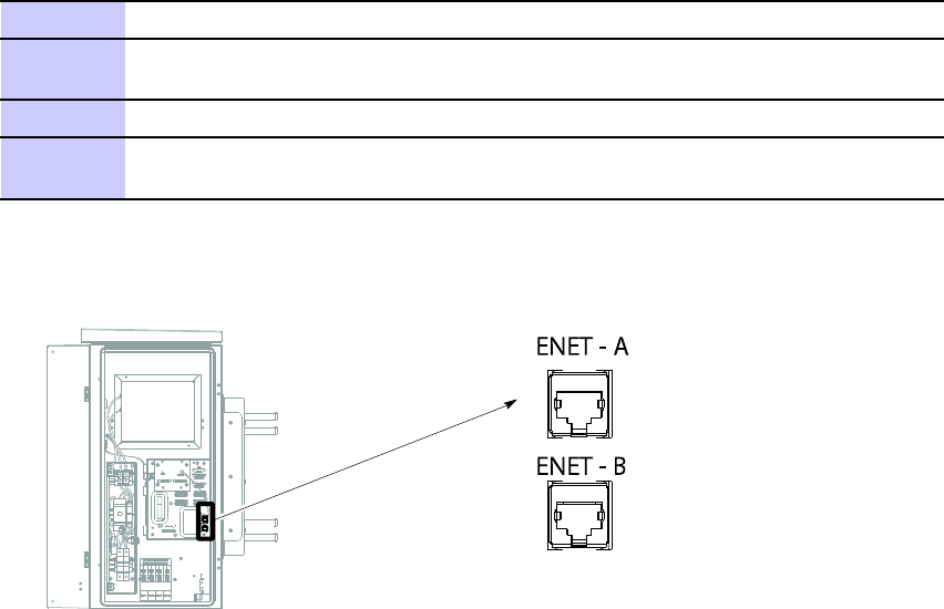
F ollow the steps in Procedure 4 -8 to install the ethernet cables.
Procedure 4 -8 Procedure to Install Ethernet Cables
1
If not already done, remove conduit plug at the bottom of the B CU .
2
If Ethernet cables are present, route them through conduit and through
access hole in the bottom of the B CU .
3
Insert cable connectors in the sockets labeled ENET A and ENET B.
4
If there are no more cables to connect close and lock Customer Interface
compartment.
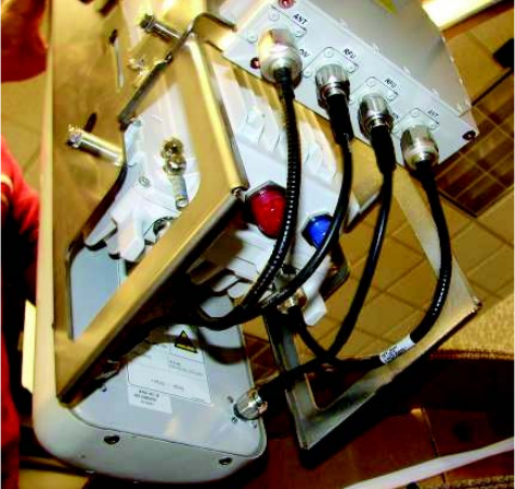
Figure 4 -16 Ethernet Cable Connection
ti-cdma-04184.eps
ENET - A
ENET - A
ENET - B
ENET - B
68P09277A59 -5 4 -37
Draft OCT 2006

Fiber Optic Cabling Installation Chapter 4: Access P oint Hardw are Installation
Fiber Optic Cabling Installation■■■■■■■■■■■■■■■■■■■■■■■■■■■■■■■■■■■■■■■■■■■■■■■■■■■■■■■■■■■■■■
■
■
Objective
This section contains the procedure for installing the fiber optic cables.
Cable Description
Cable H as listed in T able 3 -1 is required for installation.
The minimum bend radius for this cable is 90 mm.
Procedure 4 -9 Procedure to Install Fiber Optic Cables
1
Before routing the Fiber Optic cable up the
tower , verify that is properly color coded.
Red — RF Head 1
Blue — RF Head 2
Y ellow — RF Head 3
Green — RF Head 4
Color coded labels and tie-wraps can be found on the compartment
side of the door of the B CU Customer Interface compartment.
2
Connect the Fiber Optic cables to the bulkhead feedthroughs (FIBER) on the
underside of the B CU .
3
Route the cable(s) up the tower(s), bundle and secure to tower (if
RF Head is not present) or connect to the appropriate RF Head.
Use tie-wraps or appropriate clamps to secure cable to tower .
4 -38 68P09277A59 -5
Draft OCT 2006

Access P oint Hardw are Installation Customer Input/Output Cabling Installation
Customer Input/Output Cabling Installation■■■■■■■■■■■■■■■■■■■■■■■■■■■■■■■■■■■■■■■■■■■■■■■■■■■■■■■■■■■■■■
■
■
Objective
This section contains the procedures for installing the Customer Defined Input/Output cables.
Cable Descriptions
Cable F as listed in T able 3 -1 is required for installation.
Customer Input and Output Connector Pinouts
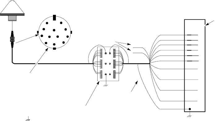
This section contains the procedures for installing the Customer Defined Input/Output cables.
The CDI/CDO cables will be routed through one inch conduit to the access hole on the underside
of the B CU .
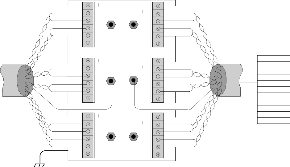
Figure 4 -17 Customer Dened Input and Output Connectors
Customer Dened Input/Output Cable Installation
F ollow the procedure in Procedure 4 -10 to install the Customer Defined Input/Output Cables
Procedure 4 -10 Procedure to Install the Customer Dened Input/Output Cables
1
If not already open, open the Customer Interface Compartment.
If not already done, remove conduit plug from access hole.
2
Route the Customer Defined Input (CDI) Cable 1–2 through conduit to the
underside of the B CU , through the access hole, and up to the connector
labeled
CUST . INP UT 1–2
3
P erform step 2 for CDI Cable 3–4.
4
Route the Customer Defined Output (CDO) Cable 1–4 through conduit to
the underside of the B CU , through the access hole, and up to the connector
labeled
CUST . OUTP UT 1–4
5
P erform step 4 for CDO Cables 5–8, 9–12, and 13–16.
6
Ensure a good connection.
Close and lock Customer Interface compartment.
68P09277A59 -5 4 -39
OCT 2006 Draft
Customer Input/Output Cabling Installation Chapter 4: Access P oint Hardw are Installation
4 -40 68P09277A59 -5
Draft OCT 2006

C h a p t e r
5
Optional Equipment
■■■■■■■■■■■■■■■■■■■■■■■■■■■■■■■■■■■■■■■■■■■■■■■■■■■■■■■■■■■■■■
■
■
■
■
68P09277A59 -5 5 -1
OCT 2006 Draft
Optional Band P ass Filters Chapter 5: Optional Equipment
Optional Band Pass Filters■■■■■■■■■■■■■■■■■■■■■■■■■■■■■■■■■■■■■■■■■■■■■■■■■■■■■■■■■■■■■■
■
■
Overview
This chapter contains general information and procedures for installing optional equipment.
Band pass filters are available as optional equipment to accommodate customers with specific
band allocations.
Filter Requirements
W eight and Dimensions The band pass filter(s) used should meet the following
requirements:
•W eight: 1.6 kg (3.5 lbs)
•Dimensions: 50 mm (2 in) Wx 150 mm (6 in) Hx 100 mm (4 in) D.
Figure 5 -1 Band P ass Filter
Filter Mounting Figure 5 -2 shows the optimal mounting position on the RF Carrier Unit
(RFCU). The filters are mounted such that cable lengths are kept to a minimum.
Figure 5 -2 Filter Mounting
5 -2 68P09277A59 -5
Draft OCT 2006
Access P oint Hardw are Installation Motorola Stabilit y Oscillator (MSO)
Motorola Stability Oscillator (MSO)■■■■■■■■■■■■■■■■■■■■■■■■■■■■■■■■■■■■■■■■■■■■■■■■■■■■■■■■■■■■■■
■
■
Overview
The Motorola Stability Oscillator (MSO) is available as optional equipment to accommodate
customers that want this backup timing module.
68P09277A59 -5 5 -3
OCT 2006 Draft
Motorola Stabilit y Oscillator (MSO) Chapter 5: Optional Equipment
5 -4 68P09277A59 -5
Draft OCT 2006

C h a p t e r
6
What’s Next and Cleanup■■■■■■■■■■■■■■■■■■■■■■■■■■■■■■■■■■■■■■■■■■■■■■■■■■■■■■■■■■■■■■
■
■
■
■
68P09277A59 -5 6 -1
OCT 2006 Draft
What ’ s Next Chapter 6: What ’ s Next and Cleanup
What’s Next■■■■■■■■■■■■■■■■■■■■■■■■■■■■■■■■■■■■■■■■■■■■■■■■■■■■■■■■■■■■■■
■
■
Introduction
Optimization is the next procedure you should perform. There are two things left to do before
you begin the optimization:
1. Clean up the site
2. Fill out the installation completion checklist
Clean Up Site
Clean up the site by following the information given in the
Site Cleanup
area in this chapter .
Fill Out Checklist
A fter the site is cleaned up, fill out the installation completion checklist. This checklist is located
in the
Installation Completion Checklist
area of this chapter .
Optimize the System
Optimize the system by following the procedures given in the appropriate optimization manual.
The hardware installation does not include card placement and turning on power . These things
and more are covered in the appropriate optimization manual.
6 -2 68P09277A59 -5
Draft OCT 2006
Access P oint Hardw are Installation Site Cleanup
Site Cleanup
■■■■■■■■■■■■■■■■■■■■■■■■■■■■■■■■■■■■■■■■■■■■■■■■■■■■■■■■■■■■■■
■
■
Tools
Place all hand and power tools in the installation tool kit or other appropriate place. Note any
tools that need replacement, cleaning, or adjustment.
Materials
Place any leftover materials in a location specified by the site manager .
Remove Debris
Remove any packing material. Ensure that all scrap materials have been removed. Clean/sweep
the floor . Ensure that all chalk line marks have been removed.
Environment
Organize any items (manuals, materials, etc.) left on site and place them in a location specified
by the site manager .
68P09277A59 -5 6 -3
Draft OCT 2006
Installation Completion Checklist Chapter 6: What ’ s Next and Cleanup
Installation Completion Checklist■■■■■■■■■■■■■■■■■■■■■■■■■■■■■■■■■■■■■■■■■■■■■■■■■■■■■■■■■■■■■■
■
■
Installation Completion Checklist
Check the items listed in T able 6 -1 .
Directions
Fill out the installation completion checklist and make any necessary copies. Y ou may copy
this check sheet as needed. The item numbers do not represent a specific order , they are
supplied for convenience.
Installation Checklist
Hardware Installation Completion Date: _______________________
Site: _________________________________________________
Serial Number: _________________________________________
Checklist Completed By: __________________________________
Checklist Reviewed By: __________________________________
6 -4 68P09277A59 -5
Draft OCT 2006

Access P oint Hardw are Installation Installation Completion Checklist
Table 6 -1 Hardw are Installation Checklist
Item
No.
Item Notes
1
Equipment is not damaged.
2
Air flow clearance requirements are met.
3
Base Control Unit (B CU) is securely mounted to wall
or pole.
4
B CU and RF Carrier Unit (RFCU) are RF cabled
correctly .
5
B CU and RFCU are DC power cabled correctly .
6
B CU is ethernet cabled. (If installed)
7
RF Head is securely mounted to pole.
8
Band P ass filters are cabled to RFCU correctly (If
used)
9
Conduit is sufficiently grounded
10
Antennas are grounded to tower
11
The antenna cables are protected by lightning
arrestors (if applicable).
12
B CU is grounded
13
RF Head is grounded.
14
RGPS is cabled to B CU .
15
RGPS head and mast are secure.
16
RGPS connection is protected by lightning arrestors
(if applicable).
17
RGPS head has a clear view of the sky and is not in a
location which accumulates debris. Make sure the
RGPS is located away from the transmit antennas.
18
Local GPS (RF GPS) antenna is secure. (If used)
19
Local GPS cabling is installed (If used).
20
Installation hardware is removed.
21
The site is cleaned, swept and trash removed.
22
The site specific documentation is present at the site.
68P09277A59 -5 6 -5
OCT 2006 Draft
Installation Completion Checklist Chapter 6: What ’ s Next and Cleanup
6 -6 68P09277A59 -5
Draft OCT 2006

A p p e n d i x
A
Alternate Installation Procedures
68P09277A59 -5 A -1
OCT 2006 Draft

Manual RF Head Installation Procedures Appendix A: Alternate Installation Procedures
Manual RF Head Installation Procedures■■■■■■■■■■■■■■■■■■■■■■■■■■■■■■■■■■■■■■■■■■■■■■■■■■■■■■■■■■■■■■
■
■
Overview
This section contains the procedures for installing the Diversity Access P oint RF Head which is
comprised of the TRX Module and antenna radome. Refer to Figure 1–2.
DAP RF Head
Refer to Figure 1 -4 for the major components of the DAP RF Head.
Electrical Requirements
The RF Head is designed to use 40 to 59 VDC (nominal +54 VDC) supplied through the Base
Control Unit (B CU).
Dimensions and Weight
•Dimension: 228.6 mm (9 in) Wx 712 mm (28 in) Hx 406 mm (16 in) D
•W eight: 27.2 kg (60 lbs)
The dimension measurements do not include connectors, hinges, handles, or latches.
Conduit Sizes
Refer to T able A -1 for conduit sizes.
Table A -1 Conduit R equirements
No. Designation
Required Size
1
P ower
1–1/4 in
2
Fiber Optic
None
A -2 68P09277A59 -5
Draft OCT 2006

Access P oint Hardw are Installation Manual RF Head Installation Procedures
Tools and Materials
•Mounting Bracket Assembly
•U -bolts
•Set of metric sockets (3/8–in or 1/4–in)
•Set of standard sockets (3/8–in or 1/4–in)
•3/8–in or 1/4–in driver
•T orque Driver
•Cordless P ower Driver
•Ground Lug
•Crimp T ool
•T30 T orx Screw Driver
•Adjustable Crescent W rench
U -Bolt Specications
Reference Figure A -1 and T able A -2 to determine the proper U -bolt to use.
Figure A -1 U -Bolt Sizing
Table A -2 DAP U -Bolt Sizing
Nominal
Pipe Size
Pipe OD
Minimum Dimension B
Minimum Dimension C
(in) (in) (mm) (in) (mm) (in) (mm)
2 2.067 52.50 3.886 98.70 0.6 15
2.5 2.469 62.71 4.429 112.50 0.6 15
3 3.068 77.93 5.098 129.50 0.6 15
Increasing dimension B beyond that indicated above will result in a corresponding increase in dimension C
in order to maintain proper clamping force
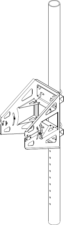
RF Head Mounting Bracket Assembly Installation
Figure A -2 shows the Mounting Bracket Assembly for the RF Head.
68P09277A59 -5 A -3
OCT 2006 Draft
Manual RF Head Installation Procedures Appendix A: Alternate Installation Procedures
Figure A -2 RF Head Mounting Br ack et Assembly
ti-cdma-04179.eps
RF Head Mounting Bracket Assembly Procedure
F ollow the steps in Procedure A -1 to install the pole mounting bracket for the RF Head.
A -4 68P09277A59 -5
Draft OCT 2006

Access P oint Hardw are Installation Manual RF Head Installation Procedures
Procedure A -1 Procedure to Install RF Head Main Support Br ack et Assembly
1
Remove nuts and plate (or washers) from both ends of the U -bolt.
2
Set Main Support Bracket Assembly at the required height.
It is recommended that two people perform attach the bracket
to the pole.
3
Slide first U -bolt around pole and through top slots of Main
Support Bracket Assembly . Slide plate (or washers) over threads.
Thread nuts on U -bolt and hand tighten.
4
Slide second U -bolt around pole and through bottom slots of Main
Support Bracket Assembly . Slide plate (or washers) over threads.
Thread nuts on U -bolt and hand tighten.
5
Align Main Support Bracket Assembly on pole facing the appropriate
direction and tighten nuts using a socket wrench or power driver . T orque
nuts to 45 in-lbs (5 N-m).
Installing the RF Head
F ollow the steps in Procedure A -2 to install the RF Head.
Procedure A -2 Procedure to Install the RF Head
1
Place the RF Head on a flat surface, large finned-side down.
2
A ttach the left and right side mounting brackets
to RF Head using a T30 T orx screw driver .
The brackets straight edges face away from Main Support Bracket Assembly .
3
If the optional filter is being used, proceed
to Procedure A-3 to attach it to the RF Head.
Otherwise, proceed with step 4
4
A ttach solar shield to side brackets by snapping the tabs on the bottom of the
shield into side bracket slots. Refer to Figure A-3 .
5
Lift shield and drop over the top of the RF Head.
Handle of RF Head slips through slot in solar shield.
Tighten two captive screws on solar shield to secure it to side mounting
bracket. T orque captive screws to 45 in-lbs (8.2 N-m)
6
Set the RF Head so that it is resting on the side brackets support arms and
RF Head bottom (filter if attached).
68P09277A59 -5 A -5
OCT 2006 Draft
Manual RF Head Installation Procedures Appendix A: Alternate Installation Procedures
Procedure A -2 Procedure to Install the RF Head (Continued)
7
Install the antenna (R adome). Hook the antenna top support
brackets over the bolts near the top of the RF Head.
Loosen antenna hook bolts as required.
Push the bottom of the antenna and hook those brackets
over the bolts near the bottom of the RF Head.
8
Secure antenna using a 10 mm socket and driver to tighten the 4 screws.
T orque the bolts to 45 in-lbs (8.2 N-m).
9
A ttach RF cables between antenna and RF Head.
T orque the bolts to 30 in-lbs (3.4 N-m).
If the Filter is used, connect antenna to RF Filter , then to
RF Head. Refer to Figure A-4 .
10
If more than one RF Head is in use tag the DC P ower cable pairs using
the color coded labels supplied inside the B CU Customer Interface
compartment. Label the cables RFU1 through RFU4 as required.
Place the color coded labesl close to the DC power and Fiber Optic connectors.
1 1
Connect DC power cables to RF Heads.
If not already done, use the color tie-wraps
to mark the cables near the connector .
Ensure that the cable for RFU 1 uses the Red tie-wrap, RFU 2 —
Blue, RFU 3 — Y ellow , and RFU 4 — Green.
Route DC power cables to bottom of the B CU and connect to RFU 1 —RFU
4 connectors in the B CU Customer Interface compartment. The B CU RFU
1 — RFU 4 connector locations are color coded.
12
A ttach (crimp) ground wire to ground lug.
A ttach opposite end of ground wire to master ground.
A ttach ground lug to RF Head.
Do the same for the remaining ground lugs, if
any .
13
Connect Fiber Optic Cables (color coded as well) to RF Head.
T orque nut 18 in-lbs (2.1 N-m).
14
A t this point, proceed to the Site Commissioning document for B CU and RF
Head test information and operational verification.
15
The B CU and RF Head have been verified as operational, proceed with step 16 .
16
V erify that the DC power cables are disconnected from the B CU .
A -6 68P09277A59 -5
Draft OCT 2006

Access P oint Hardw are Installation Manual RF Head Installation Procedures
Procedure A -2 Procedure to Install the RF Head (Continued)
17
A ttach solar shield.
Insert mushroom head knobs near bottom of shield
into keyhole slots on sides of mounting bracket.
Slide solar shield into position over handle
and into slots on top of mounting bracket.
Tighten screws to secure shield to brackets.
18
Prepare the RF Head for hoisting.
A ttach carabiner to handle of RF Head.
Use the block and tackle to hoist the RF
Head to the Main Support Bracket Assembly .
Carefully hoist RF Head (so cables will not be damaged) to Main Support
Bracket Assembly .
19
Loosen retention bracket screws on main support bracket.
Align to captive screws on side support bracket with the Main Support
Bracket Assembly curved slots and drop into place. (Retention
brackets on each side of the Main Support Bracket Assembly
should automatically slide upward to help hold the RF Head.)
If not, slide retention bracket on Main Support Bracket Assembly
up, aligning the RF Head screw with captive nut on the side support
bracket. Hand tighten captive screw . Do not fully tighten screw .
Refer to Figure A-3 .
20
Ensure that the RF Head is properly
mounted and its movement is not obstructed.
Adjust the azimuth (up/down angle) loosen two M6 screws
on each side of unit uisng a 10 mm socket or crescent
wrench. R ange of motion is 25 degrees from horizontal.
The retention bracket serves as an indicator of the azimuth in degrees.
When RF Head is set at the desired position, tighten captive
screws on retention bracket. T orque bolts to 45 in-lbs (8.2 N-m).
Tighten captive screws at pivot of each side of unit to secure RF Head.
T orque bolts to 45 in-lbs (8.2 N-m).
21
Route DC power cables through conduit to underside of
the B CU and up into the Customer Interface compartment.
Connect the color coded cables to the appropriate RF U connector .
22
Route Fiber Optic cables down the tower to the under side of the B CU .
Connect cable to the appropriate FIBER feedthrough connector .
68P09277A59 -5 A -7
OCT 2006 Draft
Manual RF Head Installation Procedures Appendix A: Alternate Installation Procedures
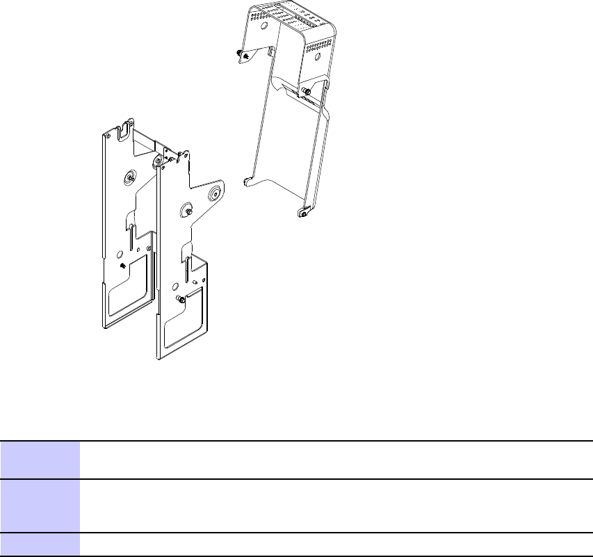
Figure A -3 RF Head Side Mounting Br ack ets and Solar Shield
ti-cdma-04195.eps
Procedure A -3 Procedure to Install Optional RF Filter
1
From Procedure A-2 ,step 3 , attach the filter mounting plate to the rear of
the RF Filter using four screws. T orque screws to 45 in-lbs (5 N-m).
2
Hook filter mounting plate to side support brackets. Secure filter mounting
plate to side support brackets by tightening the filter mounting plate captive
screws.
3
Return to Procedure A-2 ,step 4 .
A -8 68P09277A59 -5
Draft OCT 2006
Access P oint Hardw are Installation Manual RF Head Installation Procedures
Figure A -4 Antenna to Filter RF Cable Connection Diagr am
ti-cdma-04200.eps
68P09277A59 -5 A -9
OCT 2006 Draft