Nokia Solutions and Networks T7GT1 2.5GHz DIVERSITY ACCESS POINT User Manual USERS MANUAL 4 OF 4
Nokia Solutions and Networks 2.5GHz DIVERSITY ACCESS POINT USERS MANUAL 4 OF 4
Contents
- 1. USERS MANUAL 1 OF 4
- 2. USERS MANUAL 2 OF 4
- 3. USERS MANUAL 3 OF 4
- 4. USERS MANUAL 4 OF 4
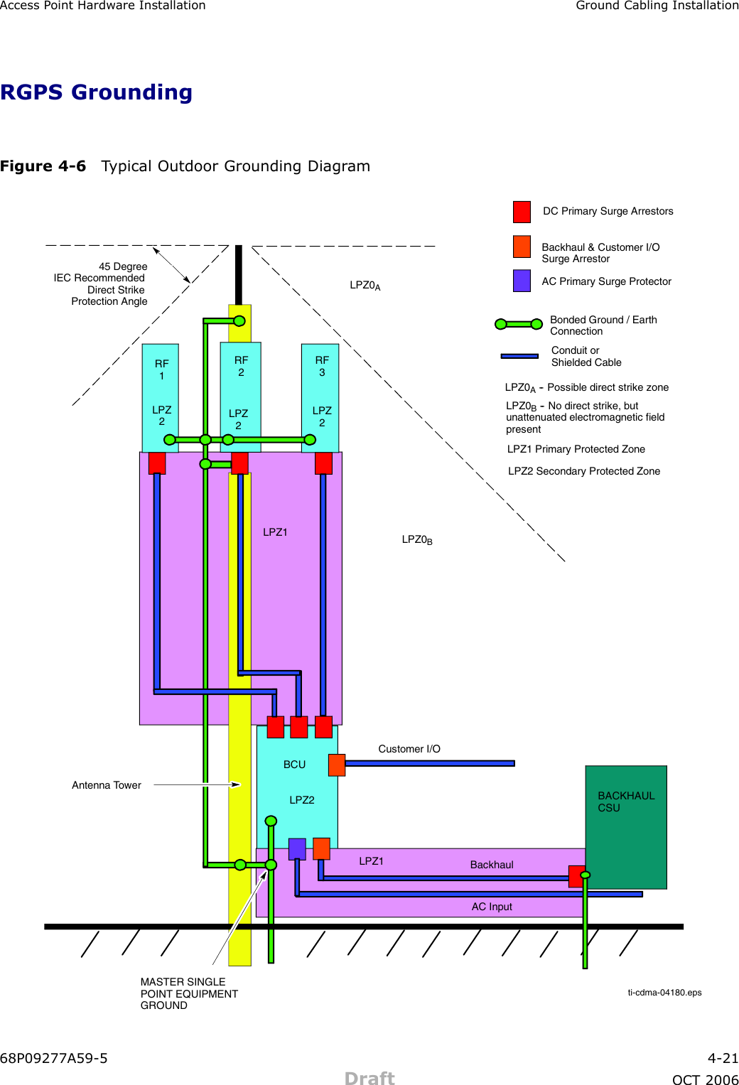
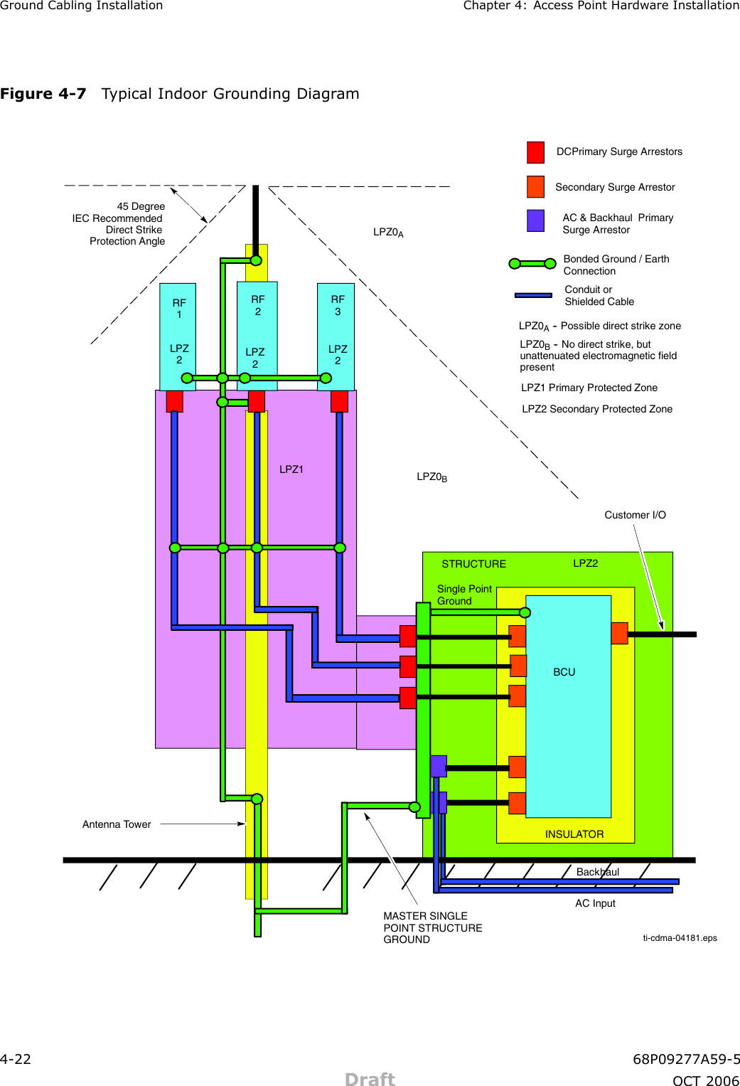
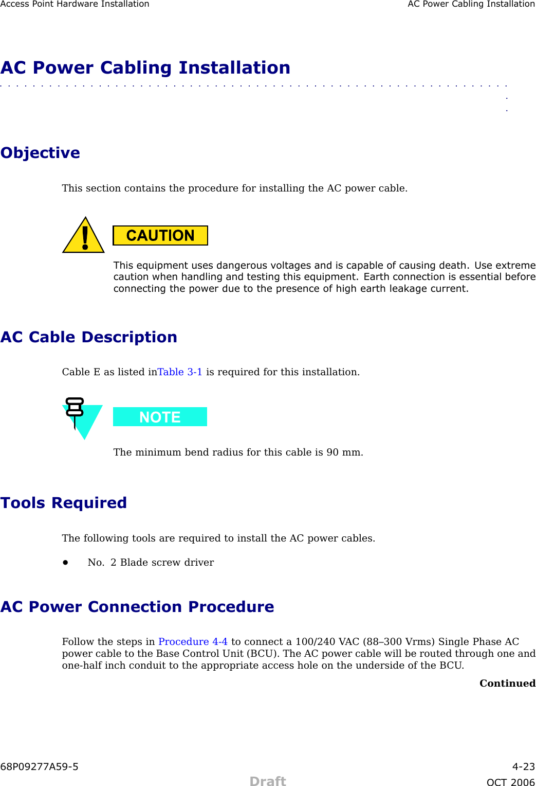
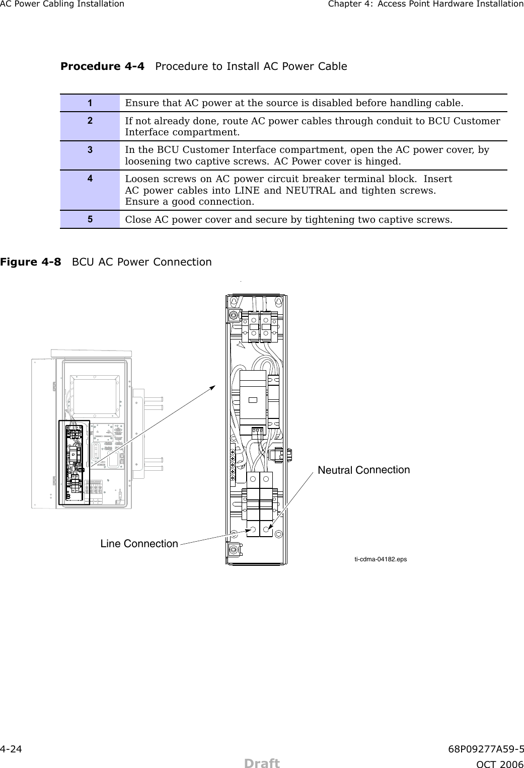
USERS MANUAL 4 OF 4