Nokia Solutions and Networks T7GT1 2.5GHz DIVERSITY ACCESS POINT User Manual USERS MANUAL 1 OF 4
Nokia Solutions and Networks 2.5GHz DIVERSITY ACCESS POINT USERS MANUAL 1 OF 4
Contents
- 1. USERS MANUAL 1 OF 4
- 2. USERS MANUAL 2 OF 4
- 3. USERS MANUAL 3 OF 4
- 4. USERS MANUAL 4 OF 4
USERS MANUAL 1 OF 4

M APPLICANT: MOTOROLA
Networks FCC ID: IHET7GT1
FCC Filing – WAP25400 MOTOwi4™ Diversity Access Point @ 2.5 GHz 1 of 1
Users Manual Exhibit
2.5GHz Diversity Access Point

Notice
While reasonable efforts have been made to assure the accuracy of this document, Motorola,
Inc. assumes no liability resulting from any inaccuracies or omissions in this document, or
from use of the information obtained herein. The information in this document has been
carefully checked and is believed to be entirely reliable. However , no responsibility is as-
sumed for inaccuracies or omissions. Motorola, Inc. reserves the right to make changes to
any products described herein and reserves the right to revise this document and to make
changes from time to time in content hereof with no obligation to notify any person of revi-
sions or changes. Motorola, Inc. does not assume any liability arising out of the application
or use of any product, software, or circuit described herein; neither does it convey license
under its patent rights or the rights of others.
It is possible that this publication may contain references to, or information about Motorola
products (machines and programs), programming, or services that are not announced in
your country . Such references or information must not be construed to mean that Motorola
intends to announce such Motorola products, programming, or services in your country .
Copyrights
This instruction manual, and the Motorola products described in this instruction manual may
be, include or describe copyrighted Motorola material, such as computer programs stored
in semiconductor memories or other media. Laws in the United States and other countries
preserve for Motorola and its licensors certain exclusive rights for copyrighted material, in-
cluding the exclusive right to copy , reproduce in any form, distribute and make derivative
works of the copyrighted material. Accordingly , any copyrighted material of Motorola and its
licensors contained herein or in the Motorola products described in this instruction manual
may not be copied, reproduced, distributed, merged or modified in any manner without the
express written permission of Motorola. Furthermore, the purchase of Motorola products
shall not be deemed to grant either directly or by implication, estoppel, or otherwise, any
license under the copyrights, patents or patent applications of Motorola, as arises by oper-
ation of law in the sale of a product.
Usage and Disclosure Restrictions
License Agreements
The software described in this document is the property of Motorola, Inc and its licensors.
It is furnished by express license agreement only and may be used only in accordance with
the terms of such an agreement.
Copyrighted Materials
Software and documentation are copyrighted materials. Making unauthorized copies is pro-
hibited by law . No part of the software or documentation may be reproduced, transmitted,
transcribed, stored in a retrieval system, or translated into any language or computer lan-
guage, in any form or by any means, without prior written permission of Motorola, Inc.
High Risk Materials
Components, units, or third -party products used in the product described herein are NOT
fault -tolerant and are NOT designed, manufactured, or intended for use as on -line control
equipment in the following hazardous environments requiring fail -safe controls: the opera-
tion of Nuclear F acilities, Aircraft Navigation or Aircraft Communication Systems, Air Traffic
Control, Life Support, or W eapons Systems (High Risk Activities). Motorola and its sup-
plier(s) specifically disclaim any expressed or implied warranty of fitness for such High Risk
Activities.
T rademarks
Motorola and the Stylized M Logo are registered in the US P atent & Trademark Office. All
other product or service names are the property of their respective owners.
Draft OCT 2006

T a b l e
o f
C o n t e n t s
Contents
■■■■■■■■■■■■■■■■■■■■■■■■■■■■■■■■■■■■■■■■■■■■■■■■■■■■■■■■■■■■■■
■
■
■
■
Access Point Hardware Installation
Revision History ......................................... 2
Version Information ..................................... 2
General information ..................................... 2
Contacting Motorola ....................................... 5
Errors ............................................ 5
Questions and comments .................................. 5
24 hour support ....................................... 5
Security Advice ......................................... 6
W arnings and cautions ...................................... 7
F ailure to comply with warnings . . . . . . . . . . . . . . . . . . . . . . . . . . . . . . . 7
W arnings ........................................... 7
Cautions ........................................... 7
Notes ............................................ 8
General Safety .......................................... 9
Ground the equipment .................................... 9
Do not operate in an explosive atmosphere . . . . . . . . . . . . . . . . . . . . . . . . . 9
K eep away from live circuits . . . . . . . . . . . . . . . . . . . . . . . . . . . . . . . . . 9
Do not service or adjust alone . . . . . . . . . . . . . . . . . . . . . . . . . . . . . . . . 9
Use caution when exposing or handling the CR T . . . . . . . . . . . . . . . . . . . . . . . 10
Do not substitute parts or modify equipment . . . . . . . . . . . . . . . . . . . . . . . . 10
P otentially hazardous procedure warnings . . . . . . . . . . . . . . . . . . . . . . . . . . 10
Devices sensitive to static . . . . . . . . . . . . . . . . . . . . . . . . . . . . . . . . . . . . 11
Special handling techniques . . . . . . . . . . . . . . . . . . . . . . . . . . . . . . . . . 11
Caring for the environment . . . . . . . . . . . . . . . . . . . . . . . . . . . . . . . . . . . 12
Disposal of Motorola Networks equipment in EU countries . . . . . . . . . . . . . . . . . 12
Disposal of Motorola Networks equipment in non -EU countries . . . . . . . . . . . . . . . 12
Third P arty Computer Software and Trademarks . . . . . . . . . . . . . . . . . . . . . . . . 13
Computer Software ..................................... 13
Trademarks ......................................... 13
Motorola manual set ....................................... 14
Ordering manuals and CD -ROMs . . . . . . . . . . . . . . . . . . . . . . . . . . . . . . 14
Manual banner definitions . . . . . . . . . . . . . . . . . . . . . . . . . . . . . . . . . . 14
Chapter 1: Introduction
Introduction ........................................... 1 - 2
Overview ........................................... 1 - 2
Manual Order ........................................ 1 - 2
Product Description ..................................... 1 - 3
Recommended Documents .................................. 1 - 3
Abbreviations and Acronyms . . . . . . . . . . . . . . . . . . . . . . . . . . . . . . . . . 1 - 3
Tools and Materials ....................................... 1 - 5
68P09277A59 -5 i
OCT 2006 Draft
Contents
Introduction ......................................... 1 - 5
Tools and Materials ..................................... 1 - 5
Base Control Unit Hardware Identification . . . . . . . . . . . . . . . . . . . . . . . . . 1 - 6
RF Head Hardware Identification . . . . . . . . . . . . . . . . . . . . . . . . . . . . . . 1 - 6
Access P oint Equipment Identification . . . . . . . . . . . . . . . . . . . . . . . . . . . . . . 1 - 8
Introduction ......................................... 1 - 8
B CU Hardware Identification . . . . . . . . . . . . . . . . . . . . . . . . . . . . . . . . 1 - 8
RF Head Hardware Identification . . . . . . . . . . . . . . . . . . . . . . . . . . . . . . 1 - 10
Chapter 2: Site Preparation
Site Preparation Overview .................................... 2 - 2
Overview ........................................... 2 - 2
Installation .......................................... 2 - 2
Site Manager ........................................ 2 - 2
V erification and Procedures . . . . . . . . . . . . . . . . . . . . . . . . . . . . . . . . . 2 - 2
Prepare Site for Equipment Arrival . . . . . . . . . . . . . . . . . . . . . . . . . . . . . . . 2 - 3
Description ......................................... 2 - 3
Equipment Arrival ...................................... 2 - 3
Procedure to Prepare the Site for the Equipment . . . . . . . . . . . . . . . . . . . . . . 2 - 3
Shipping and Handling ...................................... 2 - 4
Overview ........................................... 2 - 4
How Equipment is Shipped . . . . . . . . . . . . . . . . . . . . . . . . . . . . . . . . . 2 - 4
How Equipment Arrives ................................... 2 - 4
Unpacking .......................................... 2 - 4
Recommended Tools ..................................... 2 - 4
Unpacking Diagrams ..................................... 2 - 5
Unpacking a Cardboard Container or Shrink W rapped Shipment . . . . . . . . . . . . . . 2 - 7
Chapter 3: Cable Descriptions
Cable Descriptions ........................................ 3 - 2
Overview ........................................... 3 - 2
Configurations Supported . . . . . . . . . . . . . . . . . . . . . . . . . . . . . . . . . . 3 - 2
Cable Installation Order ................................... 3 - 2
Cable Labels ......................................... 3 - 2
Cable Descriptions and P art Numbers . . . . . . . . . . . . . . . . . . . . . . . . . . . . 3 - 3
Cable Lengths ........................................ 3 - 4
Earth Ground and P ower Cables . . . . . . . . . . . . . . . . . . . . . . . . . . . . . . . . . 3 - 5
Grounding Considerations . . . . . . . . . . . . . . . . . . . . . . . . . . . . . . . . . . 3 - 5
Power Considerations .................................... 3 - 5
DC Power (RF Head) ..................................... 3 - 5
Antenna Cable .......................................... 3 - 7
Objective ........................................... 3 - 7
Cable Label ......................................... 3 - 7
Antenna Cable Pin and Signal Information . . . . . . . . . . . . . . . . . . . . . . . . . . 3 - 7
Remote GPS Cable ........................................ 3 - 8
Objective ........................................... 3 - 8
Cable Label ......................................... 3 - 8
RGPS Cables ......................................... 3 - 8
Mounting Considerations . . . . . . . . . . . . . . . . . . . . . . . . . . . . . . . . . . 3 - 8
RF GPS Cable .......................................... 3 - 10
Objective ........................................... 3 - 10
Cable Label ......................................... 3 - 10
Surge Protection ....................................... 3 - 10
Mounting Considerations . . . . . . . . . . . . . . . . . . . . . . . . . . . . . . . . . . 3 - 10
Ethernet Cable .......................................... 3 - 12
Objective ........................................... 3 - 12
ii 68P09277A59 -5
Draft OCT 2006
Access P oint Hardw are Installation Contents
Cable Label ......................................... 3 - 12
Tools and Materials ..................................... 3 - 12
Fiber Optic Cable ........................................ 3 - 13
Objective ........................................... 3 - 13
Cable Label ......................................... 3 - 13
Cable Description and P art Number . . . . . . . . . . . . . . . . . . . . . . . . . . . . . 3 - 13
Customer Defined Input/Output Cables . . . . . . . . . . . . . . . . . . . . . . . . . . . . . 3 - 14
Objective ........................................... 3 - 14
Cable Label ......................................... 3 - 14
Cable Descriptions and P art Numbers . . . . . . . . . . . . . . . . . . . . . . . . . . . . 3 - 14
Customer Defined Input and Output Connector Pinouts . . . . . . . . . . . . . . . . . . . 3 - 15
Chapter 4: Access Point Hardware Installation
Installation Overview ...................................... 4 - 2
Overview ........................................... 4 - 2
Procedure Order ....................................... 4 - 2
Installation Kits ....................................... 4 - 3
GPS Kits ........................................... 4 - 4
Connector Locations ....................................... 4 - 5
Base Control Unit Connector Locations . . . . . . . . . . . . . . . . . . . . . . . . . . . 4 - 5
RF Head Connector Locations . . . . . . . . . . . . . . . . . . . . . . . . . . . . . . . . 4 - 5
Base Control Unit Installation . . . . . . . . . . . . . . . . . . . . . . . . . . . . . . . . . . 4 - 6
Overview ........................................... 4 - 6
B CU Compartments ..................................... 4 - 6
Electrical .......................................... 4 - 8
Battery Backup ....................................... 4 - 9
Dimension and W eight .................................... 4 - 9
Conduit Sizes ........................................ 4 - 9
Tools and Materials ..................................... 4 - 9
B CU Mounting Bracket Assembly Installation . . . . . . . . . . . . . . . . . . . . . . . . 4 - 10
B CU Mounting Bracket Assembly Procedure . . . . . . . . . . . . . . . . . . . . . . . . 4 - 11
Installing the B CU ...................................... 4 - 12
Diversity Access P oint (DAP) RF Head Assembly Installation . . . . . . . . . . . . . . . . . . 4 - 14
Overview ........................................... 4 - 14
DAP RF Head ........................................ 4 - 14
Electrical Requirements . . . . . . . . . . . . . . . . . . . . . . . . . . . . . . . . . . . 4 - 14
Dimensions and W eight ................................... 4 - 14
Conduit Sizes ........................................ 4 - 14
Tools and Materials ..................................... 4 - 15
U -Bolt Specifications ..................................... 4 - 15
RF Head Assembly Installation Procedure . . . . . . . . . . . . . . . . . . . . . . . . . . 4 - 16
Ground Cabling Installation . . . . . . . . . . . . . . . . . . . . . . . . . . . . . . . . . . . 4 - 20
Objective ........................................... 4 - 20
General Grounding Guidelines . . . . . . . . . . . . . . . . . . . . . . . . . . . . . . . . 4 - 20
B CU Grounding ....................................... 4 - 20
RF Head Grounding ..................................... 4 - 20
DC Power Grounding .................................... 4 - 20
Antenna Grounding ..................................... 4 - 20
RGPS Grounding ....................................... 4 - 21
AC P ower Cabling Installation . . . . . . . . . . . . . . . . . . . . . . . . . . . . . . . . . . 4 - 23
Objective ........................................... 4 - 23
AC Cable Description .................................... 4 - 23
Tools Required ........................................ 4 - 23
AC P ower Connection Procedure . . . . . . . . . . . . . . . . . . . . . . . . . . . . . . . 4 - 23
RF Head DC P ower Cabling Installation . . . . . . . . . . . . . . . . . . . . . . . . . . . . . 4 - 25
Objective ........................................... 4 - 25
DC Cable Description .................................... 4 - 25
68P09277A59 -5 iii
OCT 2006 Draft
Contents
Tools Required ........................................ 4 - 25
DC P ower Cable Installation . . . . . . . . . . . . . . . . . . . . . . . . . . . . . . . . . 4 - 25
Antenna Cabling Installation . . . . . . . . . . . . . . . . . . . . . . . . . . . . . . . . . . . 4 - 27
Objective ........................................... 4 - 27
Installing Antenna Cables . . . . . . . . . . . . . . . . . . . . . . . . . . . . . . . . . . 4 - 27
RGPS Cabling Installation .................................... 4 - 28
Objective ........................................... 4 - 28
Cable Description ...................................... 4 - 28
Tools Required ........................................ 4 - 28
Cable Pinout ......................................... 4 - 28
RGPS Installation ...................................... 4 - 29
Connecting the RGPS Cable to Lightning Arrestor . . . . . . . . . . . . . . . . . . . . . . 4 - 31
RF GPS Cabling Installation . . . . . . . . . . . . . . . . . . . . . . . . . . . . . . . . . . . 4 - 34
Objective ........................................... 4 - 34
Tools and Materials ..................................... 4 - 34
Cable Description ...................................... 4 - 34
Installing RF GPS Antenna and Cable . . . . . . . . . . . . . . . . . . . . . . . . . . . . 4 - 34
Ethernet Cabling Installation . . . . . . . . . . . . . . . . . . . . . . . . . . . . . . . . . . 4 - 37
Objective ........................................... 4 - 37
Cable Description ...................................... 4 - 37
Installing Ethernet Cables . . . . . . . . . . . . . . . . . . . . . . . . . . . . . . . . . . 4 - 37
Fiber Optic Cabling Installation . . . . . . . . . . . . . . . . . . . . . . . . . . . . . . . . . 4 - 38
Objective ........................................... 4 - 38
Cable Description ...................................... 4 - 38
Customer Input/Output Cabling Installation . . . . . . . . . . . . . . . . . . . . . . . . . . . 4 - 39
Objective ........................................... 4 - 39
Cable Descriptions ...................................... 4 - 39
Customer Input and Output Connector Pinouts . . . . . . . . . . . . . . . . . . . . . . . 4 - 39
Customer Defined Input/Output Cable Installation . . . . . . . . . . . . . . . . . . . . . . 4 - 39
Chapter 5: Optional Equipment
Optional Band Pass Filters .................................... 5 - 2
Overview ........................................... 5 - 2
Filter Requirements ..................................... 5 - 2
Motorola Stability Oscillator (MSO) . . . . . . . . . . . . . . . . . . . . . . . . . . . . . . . 5 - 3
Overview ........................................... 5 - 3
Chapter 6: What’s Next and Cleanup
What’s Next ........................................... 6 - 2
Introduction ......................................... 6 - 2
Clean Up Site ........................................ 6 - 2
Fill Out Checklist ...................................... 6 - 2
Optimize the System ..................................... 6 - 2
Site Cleanup ........................................... 6 - 3
Tools ............................................. 6 - 3
Materials ........................................... 6 - 3
Remove Debris ........................................ 6 - 3
Environment ......................................... 6 - 3
Installation Completion Checklist . . . . . . . . . . . . . . . . . . . . . . . . . . . . . . . . 6 - 4
Installation Completion Checklist . . . . . . . . . . . . . . . . . . . . . . . . . . . . . . 6 - 4
Directions .......................................... 6 - 4
Installation Checklist .................................... 6 - 4
Appendix A: Alternate Installation Procedures
Manual RF Head Installation Procedures . . . . . . . . . . . . . . . . . . . . . . . . . . . . A - 2
iv 68P09277A59 -5
Draft OCT 2006
Contents
Overview ........................................... A - 2
DAP RF Head ........................................ A - 2
Electrical Requirements . . . . . . . . . . . . . . . . . . . . . . . . . . . . . . . . . . . A - 2
Dimensions and W eight ................................... A - 2
Conduit Sizes ........................................ A - 2
Tools and Materials ..................................... A - 3
U -Bolt Specifications ..................................... A - 3
RF Head Mounting Bracket Assembly Installation . . . . . . . . . . . . . . . . . . . . . . A - 3
RF Head Mounting Bracket Assembly Procedure . . . . . . . . . . . . . . . . . . . . . . A - 4
Installing the RF Head .................................... A - 5
68P09277A59 -5 v
OCT 2006 Draft
Contents
vi 68P09277A59 -5
Draft OCT 2006

L i s t
o f
F i g u r e s
List of Figures
■■■■■■■■■■■■■■■■■■■■■■■■■■■■■■■■■■■■■■■■■■■■■■■■■■■■■■■■■■■■■■
■
■
■
■
Figure 1-1: B CU ......................................... 1 - 6
Figure 1-2: RF Head ....................................... 1 - 7
Figure 1-3: B CU Hardware ................................... 1 - 9
Figure 1 -4: DAP RF Head Hardware . . . . . . . . . . . . . . . . . . . . . . . . . . . . . . . 1 - 10
Figure 2 -1: Shrink W rapped Shipment . . . . . . . . . . . . . . . . . . . . . . . . . . . . . . 2 - 5
Figure 2 -2: Cardboard Shipping Container . . . . . . . . . . . . . . . . . . . . . . . . . . . 2 - 6
Figure 3 -1: Antenna Cable Detail . . . . . . . . . . . . . . . . . . . . . . . . . . . . . . . . 3 - 7
Figure 4 -1: B CU Card Cage Compartment . . . . . . . . . . . . . . . . . . . . . . . . . . . . 4 - 7
Figure 4 -2: B CU P ower and Customer Interface Compartment . . . . . . . . . . . . . . . . . 4 - 8
Figure 4 -3: B CU P ole Mounting Bracket Assembly . . . . . . . . . . . . . . . . . . . . . . . . 4 - 10
Figure 4-4: U -Bolt Sizing ..................................... 4 - 16
Figure 4 -5: RF Head Assembly . . . . . . . . . . . . . . . . . . . . . . . . . . . . . . . . . . 4 - 17
Figure 4 -6: Typical Outdoor Grounding Diagram . . . . . . . . . . . . . . . . . . . . . . . . 4 - 21
Figure 4 -7: Typical Indoor Grounding Diagram . . . . . . . . . . . . . . . . . . . . . . . . . 4 - 22
Figure 4 -8: B CU AC P ower Connection . . . . . . . . . . . . . . . . . . . . . . . . . . . . . 4 - 24
Figure 4 -9: Base Control Unit DC P ower Connection . . . . . . . . . . . . . . . . . . . . . . 4 - 26
Figure 4 -10: Connector Pins Numbering for Cables C and C1 . . . . . . . . . . . . . . . . . . 4 - 28
Figure 4-11: RGPS Head ..................................... 4 - 30
Figure 4 -12: Installing the Remote GPS Head . . . . . . . . . . . . . . . . . . . . . . . . . . 4 - 31
Figure 4 -13: RGPS to Base Control Unit Connection Diagram . . . . . . . . . . . . . . . . . . 4 - 32
Figure 4 -14: RGPS Lightning Arrestor W iring . . . . . . . . . . . . . . . . . . . . . . . . . . 4 - 33
Figure 4 -15: RF GPS Installation and Components Diagram . . . . . . . . . . . . . . . . . . . 4 - 36
Figure 4 -16: Ethernet Cable Connection . . . . . . . . . . . . . . . . . . . . . . . . . . . . . 4 - 37
Figure 4 -17: Customer Defined Input and Output Connectors . . . . . . . . . . . . . . . . . . 4 - 39
Figure 5 -1: Band P ass Filter . . . . . . . . . . . . . . . . . . . . . . . . . . . . . . . . . . . 5 - 2
Figure 5 -2: Filter Mounting . . . . . . . . . . . . . . . . . . . . . . . . . . . . . . . . . . . 5 - 2
Figure A -1: U -Bolt Sizing . . . . . . . . . . . . . . . . . . . . . . . . . . . . . . . . . . . . A - 3
Figure A -2: RF Head Mounting Bracket Assembly . . . . . . . . . . . . . . . . . . . . . . . . A - 4
Figure A -3: RF Head Side Mounting Brackets and Solar Shield . . . . . . . . . . . . . . . . . A - 8
Figure A -4: Antenna to Filter RF Cable Connection Diagram . . . . . . . . . . . . . . . . . . A - 9
68P09277A59 -5 vii
OCT 2006 Draft
List of Figures
viii 68P09277A59 -5
Draft OCT 2006

L i s t
o f
T a b l e s
List of Tables■■■■■■■■■■■■■■■■■■■■■■■■■■■■■■■■■■■■■■■■■■■■■■■■■■■■■■■■■■■■■■
■
■
■
■
T able 1: Manual version history . . . . . . . . . . . . . . . . . . . . . . . . . . . . . . . . . 2
T able 1 -1: Abbreviations and Acronyms . . . . . . . . . . . . . . . . . . . . . . . . . . . . . 1 - 4
T able 1 -2: T ools and Materials . . . . . . . . . . . . . . . . . . . . . . . . . . . . . . . . . . 1 - 5
T able 2 -1: Recommended Unpacking T ools . . . . . . . . . . . . . . . . . . . . . . . . . . . 2 - 5
T able 3 -1: Cable Description and P art Numbers . . . . . . . . . . . . . . . . . . . . . . . . . 3 - 3
T able 3 -2: Cable Length Requirements . . . . . . . . . . . . . . . . . . . . . . . . . . . . . 3 - 4
T able 3 -3: RF Head DC P ower Cable Description and P art Numbers . . . . . . . . . . . . . . . 3 - 6
T able 3 -4: Cable Description and P art Numbers . . . . . . . . . . . . . . . . . . . . . . . . . 3 - 7
T able 3 -5: Pin and Signal Information for Antenna Cable . . . . . . . . . . . . . . . . . . . . 3 - 7
T able 3 -6: Cables Needed for RGPS Connections . . . . . . . . . . . . . . . . . . . . . . . . 3 - 8
T able 3 -7: Local GPS Cable Description and P art Numbers . . . . . . . . . . . . . . . . . . . 3 - 10
T able 3 -8: Local GPS Antenna Mounting Considerations . . . . . . . . . . . . . . . . . . . . . 3 - 11
T able 3 -9: Fiber Optic Cable Description and P art Number . . . . . . . . . . . . . . . . . . . 3 - 13
T able 3 -10: Customer Defined I/O Cable Description and P art Numbers . . . . . . . . . . . . . 3 - 14
T able 3 -11: Customer Defined Input Connector Pins 1–4 and 5–8 . . . . . . . . . . . . . . . . 3 - 15
T able 3 -12: Customer Defined Input Connector Pins 9–12 and 13–16 . . . . . . . . . . . . . . 3 - 15
T able 3 -13: Customer Defined Output Connector Pins 1–2 and 3–4 . . . . . . . . . . . . . . . 3 - 16
T able 4 -1: Conduit Types and Sizes . . . . . . . . . . . . . . . . . . . . . . . . . . . . . . . 4 - 9
T able 4 -2: Conduit Requirements . . . . . . . . . . . . . . . . . . . . . . . . . . . . . . . . 4 - 14
T able 4 -3: DAP U -Bolt Sizing . . . . . . . . . . . . . . . . . . . . . . . . . . . . . . . . . . . 4 - 16
T able 4 -4: Pinout for Cables C and C1 . . . . . . . . . . . . . . . . . . . . . . . . . . . . . . 4 - 29
T able 6 -1: Hardware Installation Checklist . . . . . . . . . . . . . . . . . . . . . . . . . . . 6 - 5
T able A -1: Conduit Requirements . . . . . . . . . . . . . . . . . . . . . . . . . . . . . . . . A - 2
T able A -2: DAP U -Bolt Sizing . . . . . . . . . . . . . . . . . . . . . . . . . . . . . . . . . . . A - 3
68P09277A59 -5 ix
OCT 2006 Draft
List of T ables
x 68P09277A59 -5
Draft OCT 2006

L i s t
o f
P r o c e d u r e s
List of Procedures
■■■■■■■■■■■■■■■■■■■■■■■■■■■■■■■■■■■■■■■■■■■■■■■■■■■■■■■■■■■■■■
■
■
■
■
Procedure 2 -1: Procedure to Prepare the Site for the BTS . . . . . . . . . . . . . . . . . . . . 2 - 3
Procedure 2 -2: Unpacking Equipment from a Cardboard Container or Shrink W rap . . . . . . . 2 - 7
Procedure 2 -3: Procedure to Remove Outdoor Equipment from Container . . . . . . . . . . . . 2 - 7
Procedure 4 -1: Procedure to Install Mounting Bracket Assembly on a P ole . . . . . . . . . . . 4 - 11
Procedure 4 -2: Procedure to Install the B CU . . . . . . . . . . . . . . . . . . . . . . . . . . 4 - 12
Procedure 4 -3: Procedure to Install RF Head Assembly . . . . . . . . . . . . . . . . . . . . . 4 - 17
Procedure 4 -4: Procedure to Install AC P ower Cable . . . . . . . . . . . . . . . . . . . . . . . 4 - 23
Procedure 4 -5: Procedure to Install DC P ower Cables . . . . . . . . . . . . . . . . . . . . . . 4 - 25
Procedure 4 -6: Procedure for Installing the RGPS Head and Cabling . . . . . . . . . . . . . . 4 - 29
Procedure 4 -7: Procedure for Installing RF GPS Antenna and Cabling . . . . . . . . . . . . . . 4 - 34
Procedure 4 -8: Procedure to Install Ethernet Cables . . . . . . . . . . . . . . . . . . . . . . 4 - 37
Procedure 4 -9: Procedure to Install Fiber Optic Cables . . . . . . . . . . . . . . . . . . . . . 4 - 38
Procedure 4 -10: Procedure to Install the Customer Defined Input/Output Cables . . . . . . . . 4 - 39
Procedure A -1: Procedure to Install RF Head Main Support Bracket Assembly . . . . . . . . . A - 4
Procedure A -2: Procedure to Install the RF Head . . . . . . . . . . . . . . . . . . . . . . . . A - 5
Procedure A -3: Procedure to Install Optional RF Filter . . . . . . . . . . . . . . . . . . . . . A - 8
68P09277A59 -5 xi
OCT 2006 Draft
List of Procedures
xii 68P09277A59 -5
Draft OCT 2006

A b o u t
T h i s
M a n u a l
Access Point Hardware Installation■■■■■■■■■■■■■■■■■■■■■■■■■■■■■■■■■■■■■■■■■■■■■■■■■■■■■■■■■■■■■■
■
■
■
■
This manual contains general information and procedures for shipping and handling, site
preparation, installation, and site clean up of the Access P oint (AP) hardware.
68P09277A59 -5 1
OCT 2006 Draft

R evision History
Revision History■■■■■■■■■■■■■■■■■■■■■■■■■■■■■■■■■■■■■■■■■■■■■■■■■■■■■■■■■■■■■■
■
■
The following shows the issue status of this manual since it was first released.
Version Information
Table 1 Manual v ersion history
Manual
issue
Date of issue
Remarks
1 5/30/06
DRAFT
2 7/10/06
DRAFT Update 1
3 8/14/06
DRAFT Update 2
4 9/27/06
DRAFT Update 3
5
10/26/06
DRAFT Update 4
General information
Motorola disclaims all liability whatsoever , implied or express, for any risk of damage,
loss or reduction in system performance arising directly or indirectly out of the
failure of the customer , or anyone acting on the customers behalf , to abide by the
instructions, system parameters or recommendations made in this manual.
2 68P09277A59 -5
Draft OCT 2006

R evision History
Purpose
Motorola cellular communications manuals are intended to instruct and assist personnel in the
operation, installation and maintenance of the Motorola cellular infrastructure equipment and
ancillary devices. It is recommended that all personnel engaged in such activities be properly
trained by Motorola.
F ailure to comply with Motorola’ s oper ation, installation and maintenance instructions
ma y , in ex ceptional circumstances, lead to serious injury or death.
These manuals are not intended to replace the system and equipment training offered by
Motorola, although they can be used to supplement and enhance the knowledge gained through
such training.
Cross references
Throughout this manual, references are made to external publications, chapter numbers and
section names. The references to external publications are shown in italics. Chapter and
section name cross references are emphasized in blue text in electronic versions. These are
active links to the references.
This manual is divided into uniquely identified and numbered chapters that, in turn, are divided
into sections. Sections are not numbered, but are individually named at the top of each page,
and are listed in the table of contents.
Text conventions
The following conventions are used in the Motorola cellular infrastructure manuals to represent
keyboard input text, screen output text and special key sequences.
Input
Characters typed in at the keyboard are shown like this.
Output
Messages, prompts, file listings, directories, utilities, and environmental
variables that appear on the screen are shown like this.
68P09277A59 -5 3
OCT 2006 Draft

R evision History
Special key sequences
Special key sequences are represented as follows:
CTRL-c
Press the Control and c keys at the same time.
ALT-f
Press the Alt and f keys at the same time.
¦Press the pipe symbol key .
CR or RETURN
Press the Return key .
4 68P09277A59 -5
Draft OCT 2006
Contacting Motorola
Contacting Motorola■■■■■■■■■■■■■■■■■■■■■■■■■■■■■■■■■■■■■■■■■■■■■■■■■■■■■■■■■■■■■■
■
■
Motorola appreciates feedback from the users of our manuals.
Errors
T o report a documentation error , call the Customer Network Resolution Center (CNRC) and
provide the following information to enable CNRC to open an Service Request (SR):
•the document type
•the manual title, part number , and revision character
•the page number(s) with the error
•a detailed description of the error and if possible the proposed solution
Questions and comments
Send questions and comments regarding user documentation to the email address below:
cdma.documentation@motorola.com
24 hour support
If you have problems regarding the operation of your equipment, please contact the Customer
Network Resolution Center (CNRC) for immediate assistance. The 24 hour telephone numbers
are listed at https://mynetworksupport.motorola.com. Select Customer Network Resolution
Center contact information . F or additional CNRC contact information, contact your Motorola
account representative.
68P09277A59 -5 5
OCT 2006 Draft
Securit y Advice
Security Advice■■■■■■■■■■■■■■■■■■■■■■■■■■■■■■■■■■■■■■■■■■■■■■■■■■■■■■■■■■■■■■
■
■
Motorola systems and equipment provide configurable security parameters to be set by the
operator based on their particular operating environment. Motorola recommends setting and
using these parameters following industry recognized security practices. Security aspects
to be considered are protecting the confidentiality , integrity , and availability of information
and assets. Assets include the ability to communicate, information about the nature of the
communications, and information about the parties involved.
In certain instances Motorola makes specific recommendations regarding security practices,
however the implementation of these recommendations and final responsibility for the security
of the system lies with the operator of the system.
Please contact the Customer Network Resolution Center (CNRC) for assistance. The 24 hour
telephone numbers are listed at https://mynetworksupport.motorola.com/. Select Customer
Network Resolution Center contact information , from the menu located to the left of the
Login box. Alternatively if you do not have access to CNRC or the internet, contact the Local
Motorola Office.
6 68P09277A59 -5
Draft OCT 2006

W arnings and cautions
Warnings and cautions■■■■■■■■■■■■■■■■■■■■■■■■■■■■■■■■■■■■■■■■■■■■■■■■■■■■■■■■■■■■■■
■
■
The following describes how warnings and cautions are used in this manual and in all manuals
of this Motorola manual set.
Failure to comply with warnings
Observe all warnings during all phases of operation, installation and maintenance of the
equipment described in the Motorola manuals. F ailure to comply with these warnings,
or with specific warnings elsewhere in the Motorola manuals, or on the equipment
itself , violates safety standards of design, manufacture and intended use of the
equipment. Motorola assumes no liability for the customer ’s failure to comply with
these requirements.
Warnings
A definition and example follow below:
Denition of Warning
A warning is used to alert the reader to possible hazards that could cause loss of life, physical
injury , or ill health. This includes hazards introduced during maintenance, for example, the use
of adhesives and solvents, as well as those inherent in the equipment.
Example and format
Do not look directly into ber optic cables or data in/out connectors. Laser r adiation
can come from either the data in/out connectors or unterminated ber optic cables
connected to data in/out connectors.
Cautions
A definition and example follow below:
Denition of Caution
A caution means that there is a possibility of damage to systems, software or individual items of
equipment within a system. However , this presents no danger to personnel.
68P09277A59 -5 7
OCT 2006 Draft

W arnings and cautions
Example and format
Do not use test equipment that is bey ond its due calibr ation date; arr ange for
calibr ation to be carried out.
Notes
A definition and example follow below:
Denition of Note
A note means that there is a possibility of an undesirable situation or provides additional
information to help the reader understand a topic or concept.
Example and format
The UDR version number is configured at installation time by Motorola personnel
and is not accessible by the customer .
8 68P09277A59 -5
Draft OCT 2006

Gener al Safet y
General Safety■■■■■■■■■■■■■■■■■■■■■■■■■■■■■■■■■■■■■■■■■■■■■■■■■■■■■■■■■■■■■■
■
■
Ground the equipment
T o minimize shock hazard, the equipment chassis and enclosure must be connected to an
electrical ground. If the equipment is supplied with a three -conductor ac power cable, the
power cable must be either plugged into an approved three -contact electrical outlet or used
with a three -contact to two -contact adapter . The three -contact to two -contact adapter must
have the grounding wire (green) firmly connected to an electrical ground (safety ground) at
the power outlet. The power jack and mating plug of the power cable must meet International
Electrotechnical Commission (IEC) safety standards.
Refer to
Grounding Guideline for Cellular R adio Installations – 68P81150E62
.
Do not operate in an explosive atmosphere
Do not operate the equipment in the presence of flammable gases or fumes. Operation of any
electrical equipment in such an environment constitutes a definite safety hazard.
Keep away from live circuits
Operating personnel must:
•not remove equipment covers. Only F actory Authorized Service P ersonnel or other
qualified maintenance personnel may remove equipment covers for internal subassembly ,
or component replacement, or any internal adjustment.
•not replace components with power cable connected. Under certain conditions, dangerous
voltages may exist even with the power cable removed.
•always disconnect power and discharge circuits before touching them.
Do not service or adjust alone
Do not attempt internal service or adjustment, unless another person, capable of rendering first
aid and resuscitation, is present.
68P09277A59 -5 9
OCT 2006 Draft

Gener al Safet y
Use caution when exposing or handling the CRT
Breakage of the Cathode–R ay Tube (CR T) causes a high -velocity scattering of glass fragments
(implosion). T o prevent CR T implosion, avoid rough handling or jarring of the equipment. Only
qualified maintenance personnel wearing approved safety mask and gloves should handle the
CR T .
Do not substitute parts or modify equipment
Because of the danger of introducing additional hazards, do not install substitute parts or
perform any unauthorized modification of equipment. Contact Motorola W arranty and Repair
for service and repair to ensure that safety features are maintained.
Potentially hazardous procedure warnings
W arnings, such as the example below , precede potentially hazardous procedures throughout
this manual. Instructions contained in the warnings must be followed. Employ all other safety
precautions necessary for the operation of the equipment in the operating environment.
P otentially hazardous v oltages, capable of causing death, are present in this
equipment. Use extreme caution when handling, testing, and adjusting.
10 68P09277A59 -5
Draft OCT 2006
Devices sensitiv e to static
Devices sensitive to static■■■■■■■■■■■■■■■■■■■■■■■■■■■■■■■■■■■■■■■■■■■■■■■■■■■■■■■■■■■■■■
■
■
Certain metal oxide semiconductor (MOS) devices embody in their design a thin layer of
insulation that is susceptible to damage from electrostatic charge. Such a charge applied to the
leads of the device could cause irreparable damage.
These charges can be built up on nylon overalls, by friction, by pushing the hands into high
insulation packing material or by use of ungrounded soldering irons.
MOS devices are normally despatched from the manufacturers with the leads short circuited
together , for example, by metal foil eyelets, wire strapping, or by inserting the leads into
conductive plastic foam. Provided the leads are short circuited it is safe to handle the device.
Special handling techniques
In the event of one of these devices having to be replaced, observe the following precautions
when handling the replacement:
•Always wear a ground strap which must be connected to the electrostatic point on the
equipment.
•Leave the short circuit on the leads until the last moment. It may be necessary to replace
the conductive foam by a piece of wire to enable the device to be fitted.
•Do not wear outer clothing made of nylon or similar man made material. A cotton overall
is preferable.
•If possible work on an grounded metal surface or anti -static mat. W ipe insulated plastic
work surfaces with an anti -static cloth before starting the operation.
•All metal tools should be used and when not in use they should be placed on an grounded
surface.
•T ake care when removing components connected to electrostatic sensitive devices. These
components may be providing protection to the device.
When mounted onto printed circuit boards (PCBs), MOS devices are normally less susceptible to
electrostatic damage. However PCBs should be handled with care, preferably by their edges
and not by their tracks and pins, they should be transferred directly from their packing to the
equipment (or the other way around) and never left exposed on the workbench.
68P09277A59 -5 11
OCT 2006 Draft
Caring for the en vironment
Caring for the environment■■■■■■■■■■■■■■■■■■■■■■■■■■■■■■■■■■■■■■■■■■■■■■■■■■■■■■■■■■■■■■
■
■
The following information is provided to enable regulatory compliance with the European Union
(EU) Directive
2002/96/EC W aste Electrical and Electronic Equipment (WEEE)
when using
Motorola Networks equipment in EU countries.
Disposal of Motorola Networks equipment in EU countries
Please do not dispose of Motorola Networks equipment in landfill sites.
In the EU , Motorola Networks in conjunction with a recycling partner will ensure that equipment
is collected and recycled according to the requirements of EU environmental law .
Please contact the Customer Network Resolution Center (CNRC) for assistance. The 24 hour
telephone numbers are listed at https://mynetworksupport.motorola.com/. Select Customer
Network Resolution Center contact information . Alternatively if you do not have access
to CNRC or the internet, contact the Local Motorola Office.
Disposal of Motorola Networks equipment in non -EU countries
In non -EU countries, dispose of Motorola Networks equipment in accordance with national
and regional regulations.
12 68P09277A59 -5
Draft OCT 2006
FCC R equirements
Table 1
MPE Limits
FrequencyParameter
2500 MHz
Maximum Gain 16 dBi
Distance 0.85 cm (33.5 in)
FCC Part 15 Requirements
Part 15.19a(3) - INFORMATION TO USER
This device complies with P art 15 of the FCC Rules. Operation is subject to the
following two conditions:
1. This device may not cause harmful interference, and
2. This device must accept any interference received, including interference that
may cause undesired operation
Part 15.21 - INFORMATION TO USER
Changes or modications not expressly appro v ed b y Motorola could v oid the user ’ s
authorit y to oper ate the equipment.
28 P AR TNO
PRELIMINARY - UNDER DEVELOPMENT MMM YYYY

FCC R equirements
15.105(b) - INFORMATION TO USER
This equipment has been tested and found to comply with the limits for a Class B
digital device, pursuant to P art 15 of the FCC Rules. These limits are designed
to provide reasonable protection against harmful interference in a residential
installation. This equipment generates, uses and can radiate radio frequency
energy and, if not installed and used in accordance with the instructions, may cause
harmful interference to radio communications. However , there is no guarantee that
interference will not occur in a particular installation. If this equipment does cause
harmful interference to radio or television reception, which can be determined by
turning the equipment OFF and ON , the user is encouraged to try to correct the
interference by one or more of the following measures:
•Reorient or relocate the receiving antenna
•Increase the separation between the equipment and receiver .
•Connect the equipment into an outlet on a circuit different from that to which
the receiver is connected.
•Connect the equipment into an outlet on a circuit different from that to which
the receiver is connected.
•Consult the dealer or an experienced radio/TV technician for help.
P AR TNO 29
MMM YYYY PRELIMINARY - UNDER DEVELOPMENT
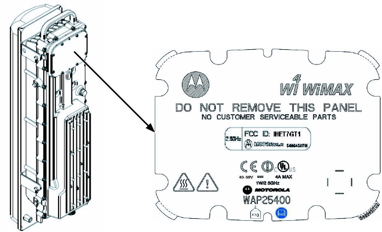
FCC R equirements
Label and Location
ti_cdma_WiMAXLabelLocation.eps
30 P AR TNO
PRELIMINARY - UNDER DEVELOPMENT MMM YYYY

Third P art y Computer Softw are and T r ademarks
Third Party Computer Software and Trademarks■■■■■■■■■■■■■■■■■■■■■■■■■■■■■■■■■■■■■■■■■■■■■■■■■■■■■■■■■■■■■■
■
■
Computer Software
The Motorola and 3rd P arty supplied Software (SW) products described in this instruction
manual may include copyrighted Motorola and other 3rd P arty supplied computer programs
stored in semiconductor memories or other media. Laws in the United States and other
countries preserve for Motorola and other 3rd P arty supplied SW certain exclusive rights for
copyrighted computer programs, including the exclusive right to copy or reproduce in any
form the copyrighted computer program. Accordingly , any copyrighted Motorola or other
3rd P arty supplied SW computer programs contained in the Motorola products described in
this instruction manual may not be copied (reverse engineered) or reproduced in any manner
without the express written permission of Motorola or the 3rd P arty SW supplier . Furthermore,
the purchase of Motorola products shall not be deemed to grant either directly or by implication,
estoppel, or otherwise, any license under the copyrights, patents or patent applications of
Motorola or other 3rd P arty supplied SW , except for the normal non -exclusive, royalty free
license to use that arises by operation of law in the sale of a product.
Vendor Copyright
Apache Software F oundation Copyright 2002-2003 All Rights Reserved
Artesyn
Copyright 2002-2003 All Rights Reserved
CMU *
Copyright 2002-2003 All Rights Reserved
Freeware T ools / Utilities * Copyright 2002-2003 All Rights Reserved
P erformance T echnologies Copyright 2002-2003 All Rights Reserved
T elelogic Copyright 2002-2003 All Rights Reserved
QNX *
Copyright 2002-2003 All Rights Reserved
*= Freeware
Trademarks
Java™ T echnology and/or J2ME™ : Java and all other Java -based marks are trademarks or
registered trademarks of Sun Microsystems, Inc. in the U .S . and other countries.
UNIX® : UNIX is a registered trademark of The Open Group in the United States and other
countries.
68P09277A59 -5 13
OCT 2006 Draft
Motorola manual set
Motorola manual set■■■■■■■■■■■■■■■■■■■■■■■■■■■■■■■■■■■■■■■■■■■■■■■■■■■■■■■■■■■■■■
■
■
The Motorola manual sets provide the information needed to install, operate, and maintain
the Motorola equipment.
Ordering manuals and CD -ROMs
W ith internet access available, to view , download, or order manuals (original or revised), visit
the Motorola Lifecycles Customer web page at https://mynetworksupport.motorola.com/, or
contact your Motorola account representative.
W ithout internet access available, order hard copy manuals or CD -ROMs with your Motorola
Local Office or Representative.
If Motorola changes the content of a manual after the original printing date, Motorola publishes
a new version with the same part number but a different revision character .
Manual banner denitions
A banner (oversized text on the bottom of the page, for example, PRELIMINARY ) indicates that
some information contained in the manual is not yet approved for general customer use.
14 68P09277A59 -5
Draft OCT 2006

C h a p t e r
1
Introduction
■■■■■■■■■■■■■■■■■■■■■■■■■■■■■■■■■■■■■■■■■■■■■■■■■■■■■■■■■■■■■■
■
■
■
■
68P09277A59 -5 1 -1
OCT 2006 Draft
Introduction Chapter 1: Introduction
Introduction
■■■■■■■■■■■■■■■■■■■■■■■■■■■■■■■■■■■■■■■■■■■■■■■■■■■■■■■■■■■■■■
■
■
Overview
This document provides information pertaining to the hardware and cabling installation for the
outdoor version of the Motorola Access P oint (AP) Hardware.
Manual Order
The manual order outlines the content make up starting with Chapter 1 and continuing through
Chapter X. A fter hardware installation has been completed, run the A TP for the system by
following the procedures defined in Chapter Y of this manual.
Chapter 1 Overview - This is a brief outline of the manual. It also provides a list of additional
documents and tools necessary to complete the procedures.
Chapter 2 Site Preparation - This chapter contains the information for site verification and
shipping and handling of the hardware.
Chapter 3 Cable Descriptions — This chapter contains general information on the cabling
available for the B CU and RF Head.
Chapter 4 Access P oint Hardware Installation — This chapter contains general information
and procedures for installing the Base Control Unit (B CU) and RF Head.
Chapter 5 Optional Equipment — This chapter contains general information and procedures
for installing optional equipment.
Chapter 6 Access P oint Hardware Operational check — This chapter contains general
information and operational checkout procedures for pre and post installation of the B CU
and RF Head.
Chapter 7 What’s Next - This chapter contains general information and procedures for site
clean up and installation checklist.
1 -2 68P09277A59 -5
Draft OCT 2006

Access P oint Hardw are Installation Introduction
Product Description
The Access P oint (AP) hardware is made up of two component assemblies: the B CU and the
RF Head. The B CU contains the signal processing and interface hardware, and the RF Head
contains the TX and RX components and B CU interface hardware.
Recommended Documents
The following documents may be required to assist in the installation of the AP Hardware.
•Grounding Guidelines for Cellular R adio Installations (Motorola part number
68P81150E62) or
Appendix C of Standards and Guidelines for Communication Sites
•Standards and Guidelines for Communication Sites
Hard copy (Motorola P art Number 6881089E50)
CD -ROM (Motorola P art Number 9882904Y01)
•Site Document (generated by Motorola Systems Engineering), which includes:
site specific documentation
channel allocation
contact list (customer)
ancillary/expendable equipment list
site wiring lists
contact list (Motorola support)
job box inventory
•Demarcation Document (Scope of W ork agreement)
•Installation manuals for non -Motorola equipment (for reference purposes).
Abbreviations and Acronyms
T able 1 -1 lists the uncommon abbreviations and acronyms that appear within the manual.
68P09277A59 -5 1 -3
Draft OCT 2006

Introduction Chapter 1: Introduction
Table 1 -1 Abbreviations and Acron yms
T erm
Denition
AP
Access P oint
B CU
Base Control Unit
CB C
Circuit Breaker Card
DAC
Direct Air Cooling
DAP
Diversity Access P oint
PSU
P ower Supply Unit
RFCU RF Carrier Unit
TRX
Transmit/Receive RF Module
1 -4 68P09277A59 -5
Draft OCT 2006

Access P oint Hardw are Installation T ools and Materials
Tools and Materials■■■■■■■■■■■■■■■■■■■■■■■■■■■■■■■■■■■■■■■■■■■■■■■■■■■■■■■■■■■■■■
■
■
Introduction
Many of the tools and materials depend on the style of the wall or pole on which the mounting
bracket is being installed. The tools and materials required to install the BTS hardware are
specified for each mounting style. Due to the variability of mounting styles, additional tools and
materials may be required to meet specific site needs.
Tools and Materials
The tools and materials listed in T able 1 -2 are recommended to properly and safely perform the
various installation procedures. Not all the tools will be used in all the procedures.
Table 1 -2 T ools and Materials
Hand T ool Materials Purpose
Adjustable T orque ratchet
and metric/standard socket
set
Customer Supplied F or general torquing of bolts and nuts.
Cordless P ower Drill, 1/4-in
or 3/8-in drive
Appropriate wood and
masonry drill bits (Standard
set may be adequate)
Customer Supplied
Drill holes in wood and light concrete
Bucklestrap Cutting T ool (Motorola P/N 6604809N01) F or the pole mounting brackets
T ape Measure
Customer Supplied General purpose measurement
Tin Snips
Customer Supplied General purpose metal cutting
Safety Glasses Customer Supplied Eye Safety
Knife or Box Cutter Customer Supplied General purpose cutting
13/16 Breakaway T orque
W rench 38-in. lb
Customer Supplied
N Connectors
Block and T ackle Customer Supplied R aising the RF Head
No . 2 Blade Screw Driver Customer Supplied General Purpose
Electrical T ape Customer Supplied General Purpose
Adjustable Crescent W rench Customer Supplied General Purpose
T30 T orx Screw Driver
Customer Supplied General Purpose
Tie- W raps
Customer Supplied General Purpose, varying lengths.
Crimp T ool Customer Supplied Ground wires
68P09277A59 -5 1 -5
Draft OCT 2006
T ools and Materials Chapter 1: Introduction
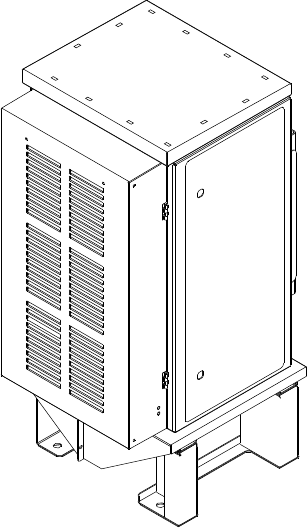
Base Control Unit Hardware Identication
Figure 1 -1 shows the B CU in an outdoor configuration.
Figure 1 -1 BCU
ti-cdma-04165.eps
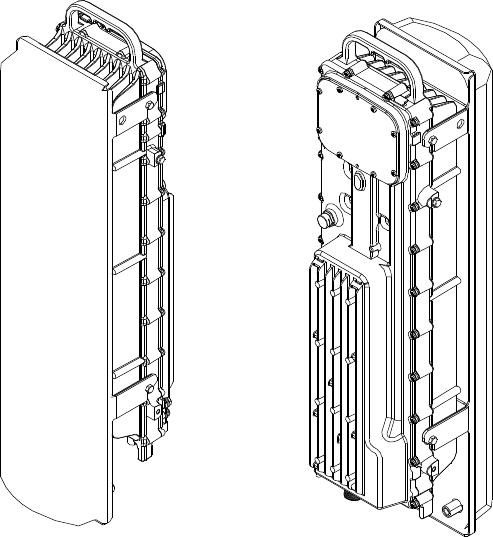
RF Head Hardware Identication
Figure 1 -2 shows the DAP RF Head hardware.
1 -6 68P09277A59 -5
Draft OCT 2006
Access P oint Hardw are Installation T ools and Materials
Figure 1 -2 RF Head
ti-cdma-04166.eps
68P09277A59 -5 1 -7
Draft OCT 2006
Access P oint Equipment Identication Chapter 1: Introduction
Access Point Equipment Identication■■■■■■■■■■■■■■■■■■■■■■■■■■■■■■■■■■■■■■■■■■■■■■■■■■■■■■■■■■■■■■
■
■
Introduction
The Base Control Unit (B CU) consists of one shelf of cards and modules within a metal
enclosure. The B CU is powered by AC or DC voltage.
BCU Hardware Identication
Figure 1 -3 displays the contents of the Base Control Unit (B CU . Except for the Mounting Bracket
Assembly all the items shown are already installed in the B CU . The number of cards installed
in the B CU card cage depends on the configuration that was ordered. Maximum number of
cards in the B CU card cage is listed below:
•1 — Alarms Card
•1 — Circuit Breaker Card
•4 — Modem Cards
•2 — Controller Cards
•3 — P ower Supply Units
The I/O P anel is always installed and is located in the Customer Interface compartment.
Heater is usually necessary if unit is used in a cold climate.
1 -8 68P09277A59 -5
Draft OCT 2006