Nokia of America ONEBTS-23 AWS DIGITAL HOST WIRELESS BASE STATION User Manual USERS MANUAL 2
Alcatel-Lucent USA Inc. AWS DIGITAL HOST WIRELESS BASE STATION USERS MANUAL 2
Contents
- 1. USERS MANUAL 1
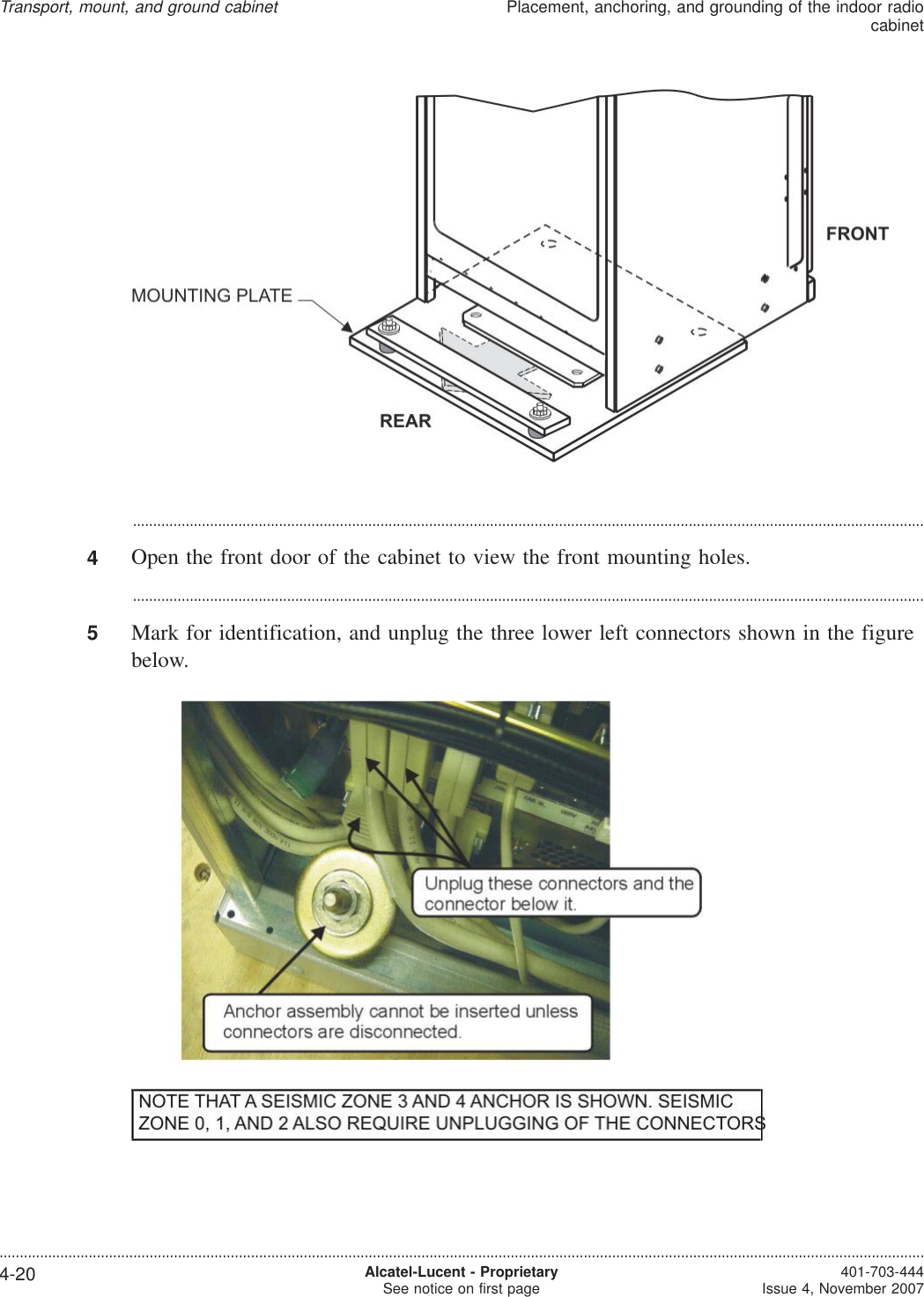
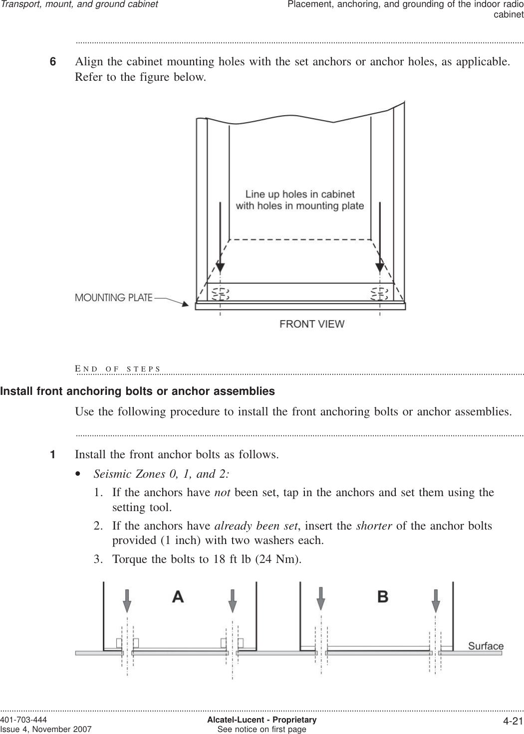
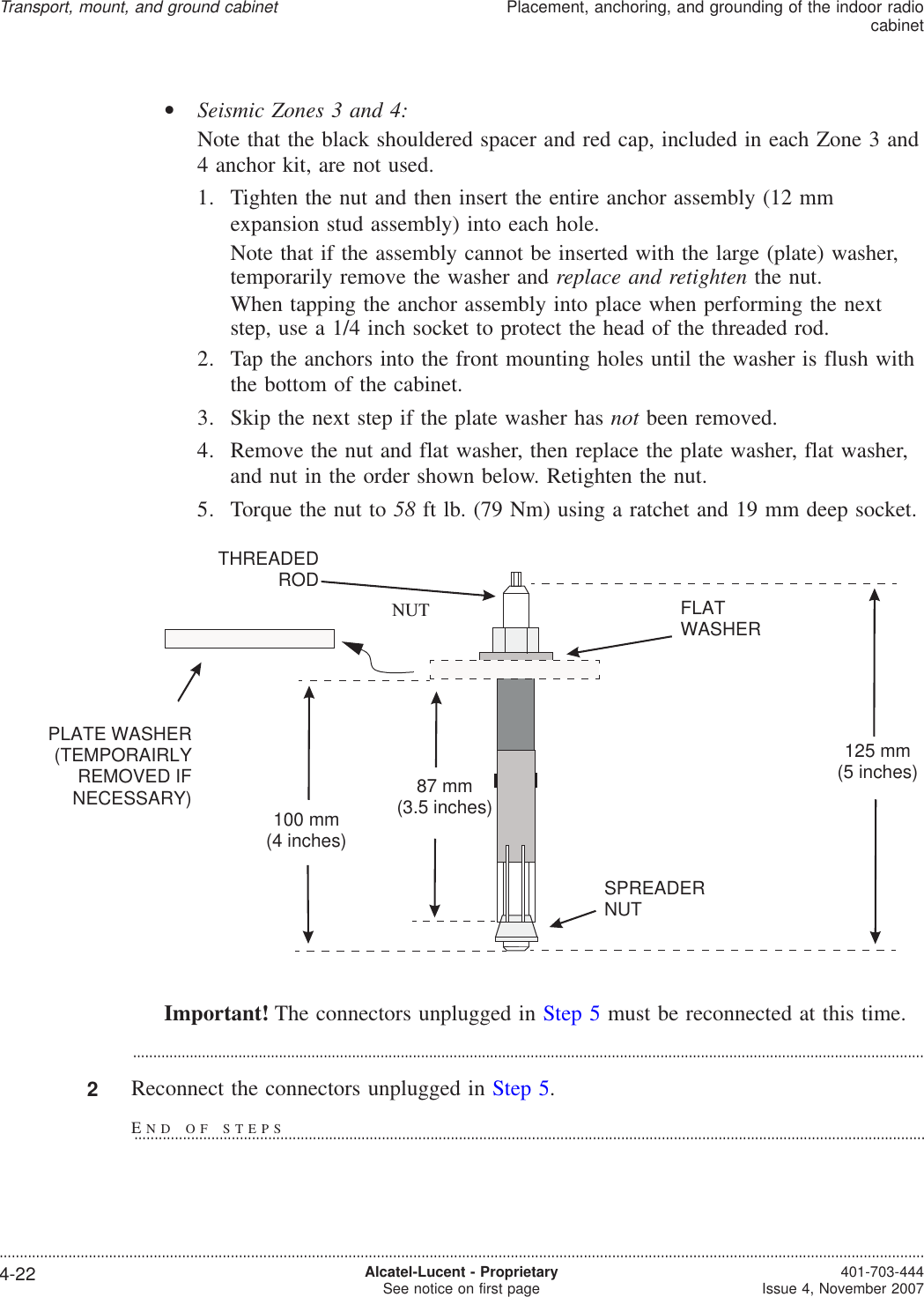
- 2. USERS MANUAL 2
- 3. USERS MANUAL 3
- 4. USERS MANUAL 4
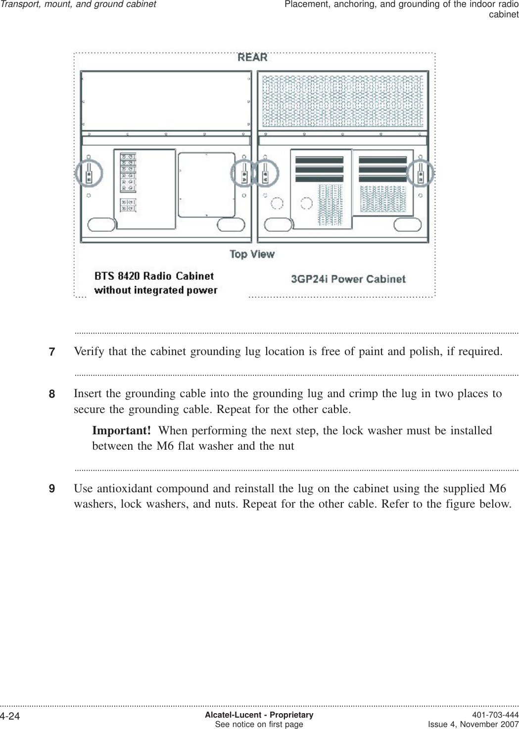
USERS MANUAL 2
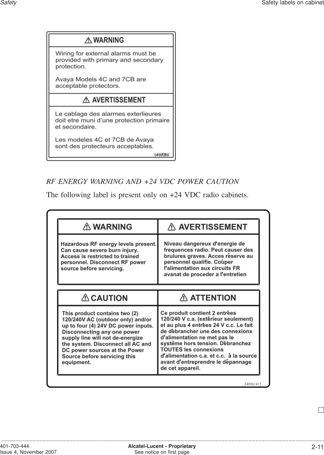
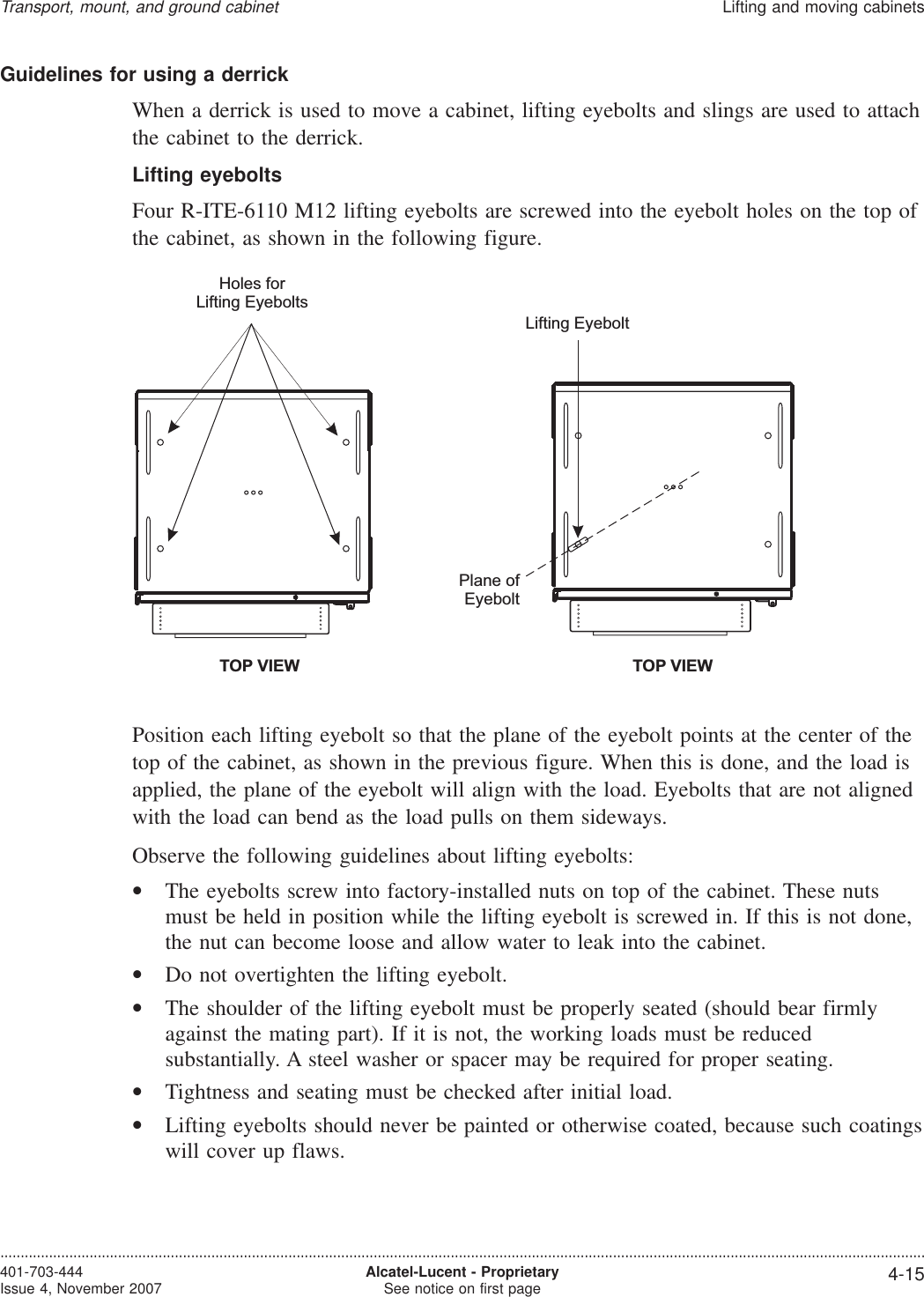
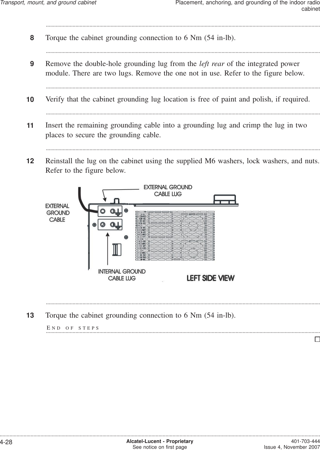
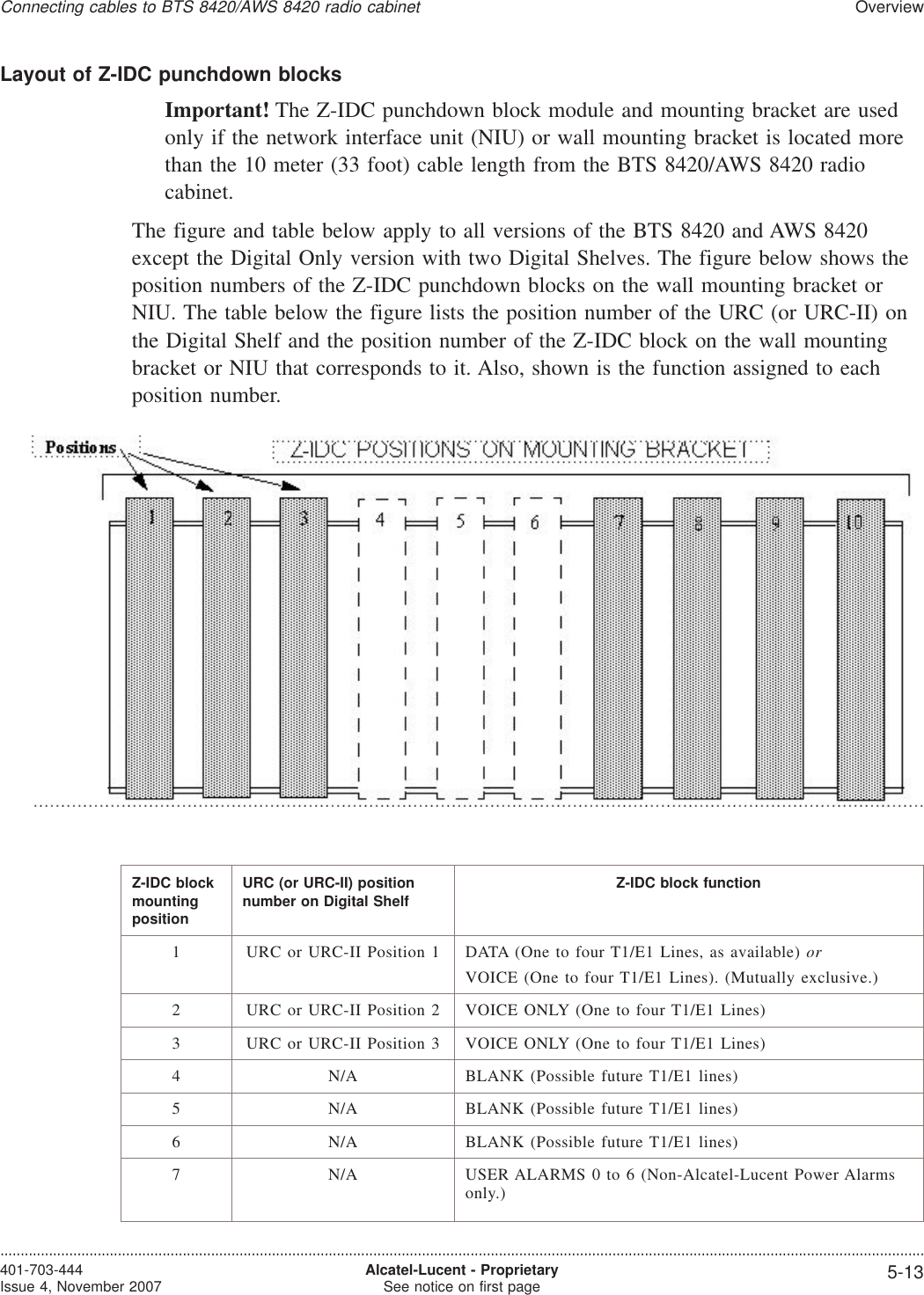
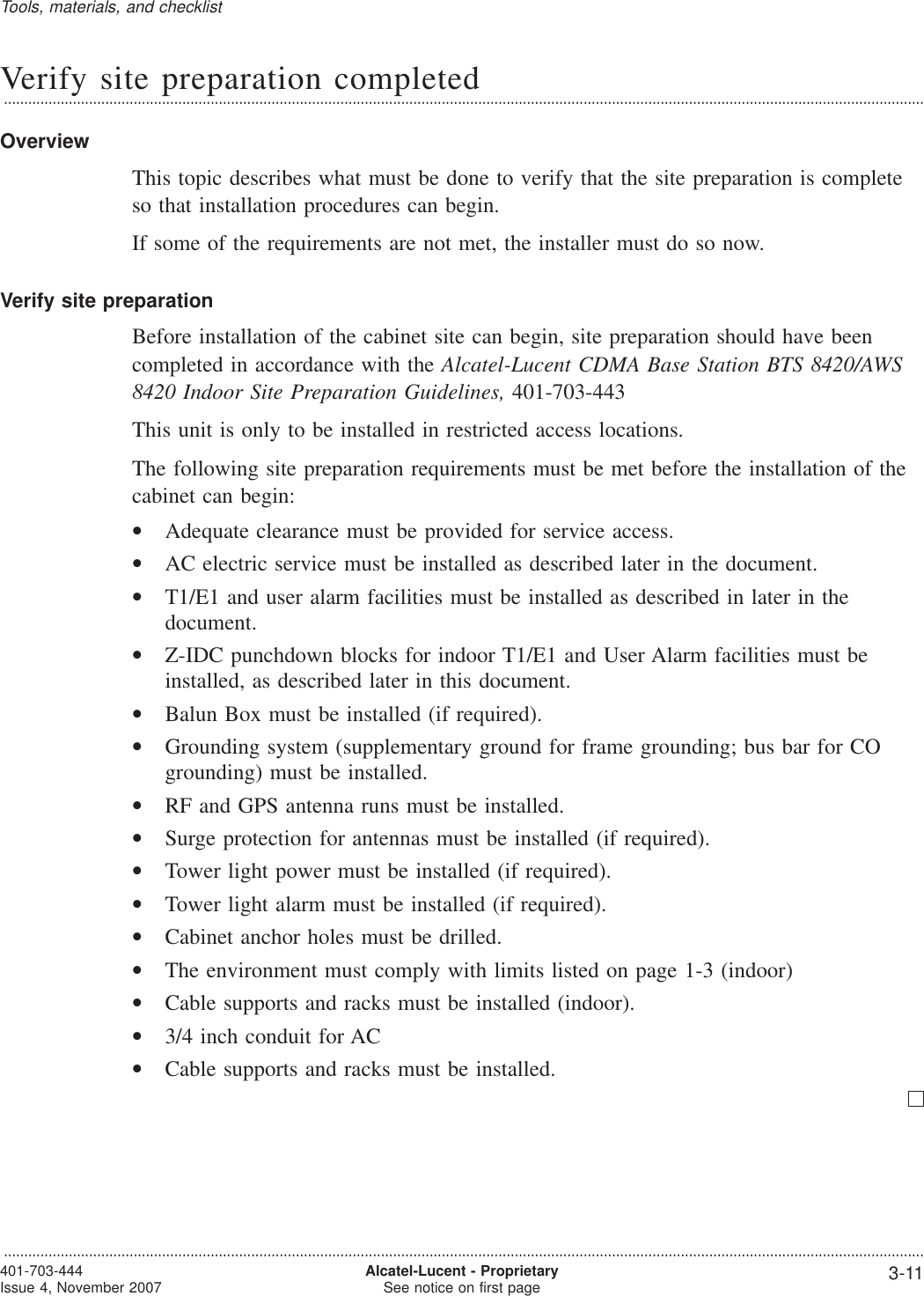
![Tools, supplies, and parts required (master list)...................................................................................................................................................................................................................................OverviewThis section provides a master list of all tools, materials, and parts required to performthe installation. If additional items are needed to perform a specific task, they are listedin the applicable chapter.ToolsCAUTIONPersonnel injury or equipment damageIf the installation is performed with energized DC circuits, be sure to use tools that areproperly insulated.The following is a master list, in alphabetical order, of all tools that may be utilizedduring installation.•Adjustable open-end wrench (or set of fixed open-end wrenches)•Antioxidant compound•B connecting links, or equivalent (quantity: 3)•Bolt anchor setting tool•Bonding clamps for facility and phone line cables (normally provided by telephonecompany)•Box cutter or equivalent, to open packaging•Chalk line•Channel-lock pliers [for 2-1/2 inch nuts, max. 19 mm (3/4 inch) wide]•Channel-lock pliers (standard)•Crimping tools, 5-120 mm2 (22-16 and 10-4/0 AWG), for installation of terminallugs and C-Taps•Derrick, capable of lifting 680-kg (1500 lb)•DIN connector stripping tool: part numbers•For Huber Suhner cable/connector: 74Z-0-12-15•For Andrew cable/connectors: ITE-7189•For RFS cable/connectors: TRIM-L12-A•Drill and drill bits [including 16 mm (5/8 inch) and 18 mm (11/16 inch) for drillinganchor holes)•Drill - Pneumatic Hammer (R-5006)Tools, materials, and checklist...................................................................................................................................................................................................................................401-703-444Issue 4, November 2007 Alcatel-Lucent - ProprietarySee notice on first page 3-3](https://usermanual.wiki/Nokia-of-America/ONEBTS-23.USERS-MANUAL-2/User-Guide-975664-Page-16.png)
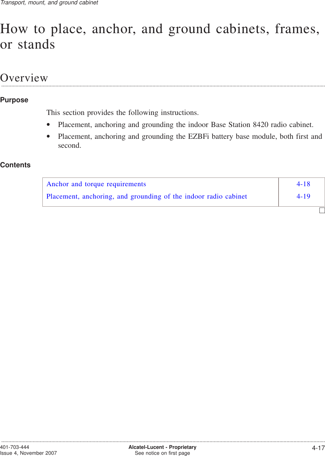
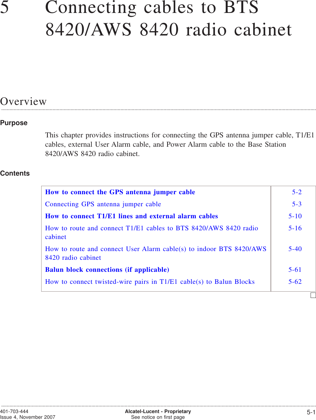
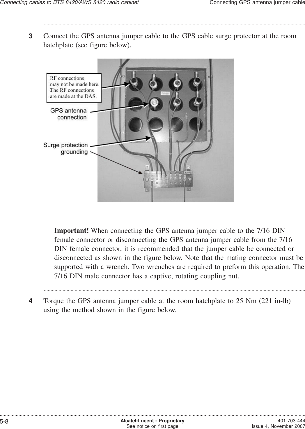
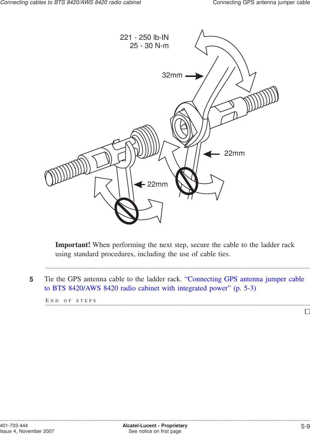
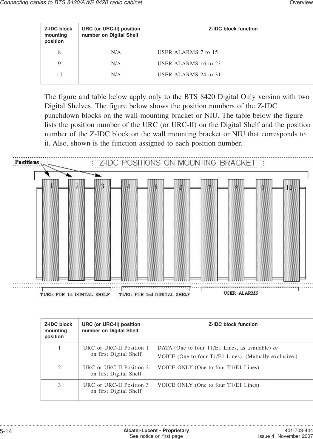
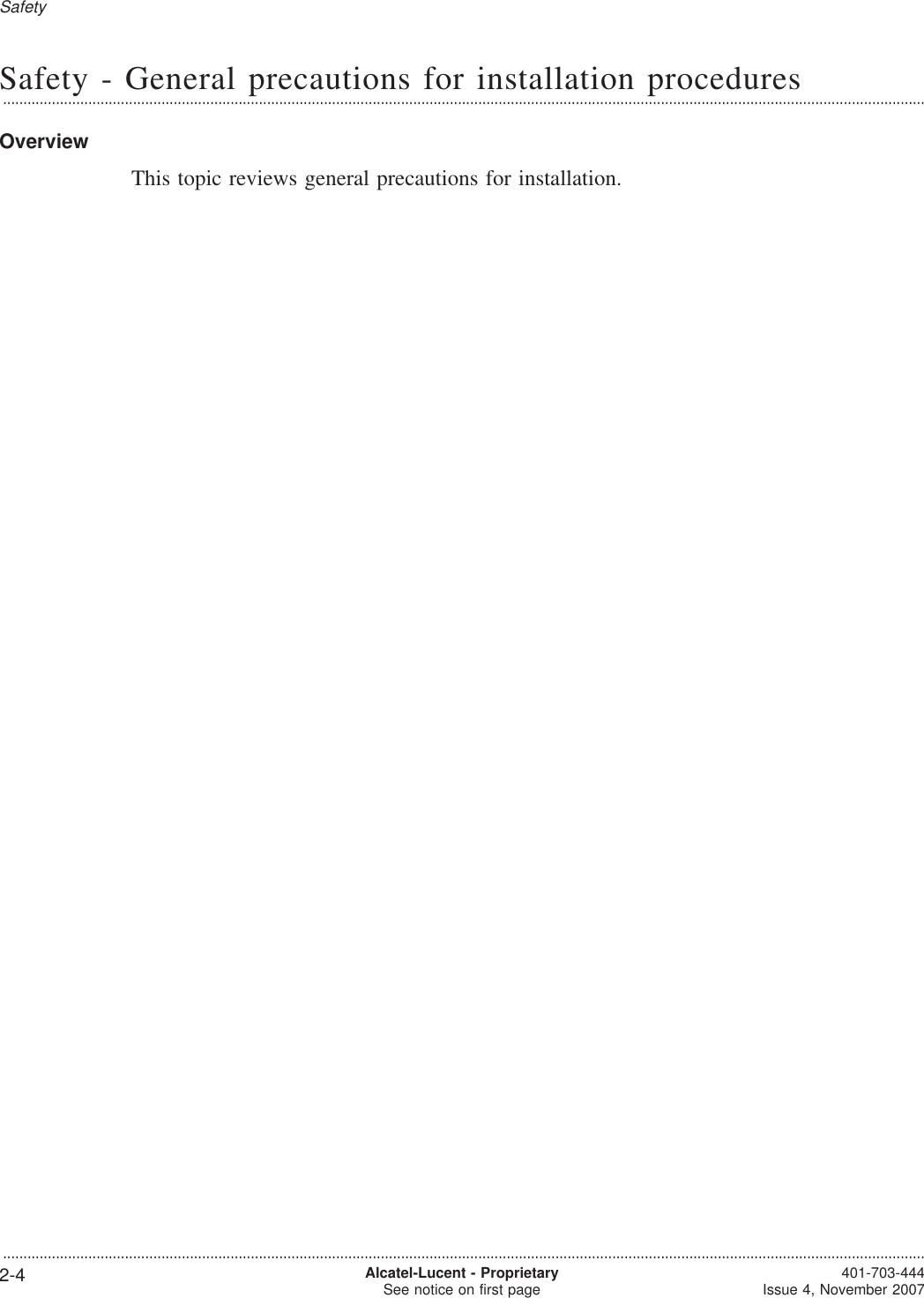
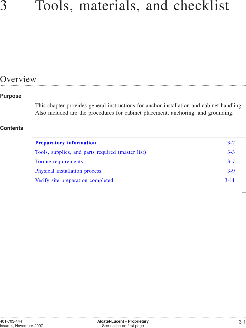
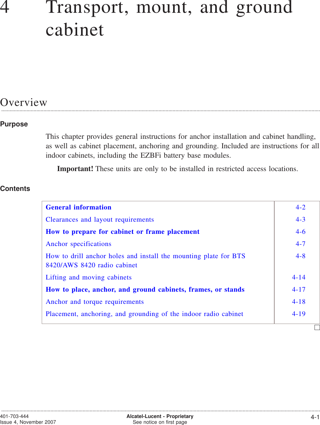
![Torque requirements...................................................................................................................................................................................................................................OverviewThis section provides mechanical torque requirements. Refer to the table below.Torque requirements for mechanical connectionsThe table below identifies the torque requirements to be followed when makingmechanical connections.Item Description TorqueNewtonMeters Inch PoundsAntenna jumper cable connections (7/16 inch DIN) 25 221GPS antenna jumper cable connection (N) at radiocabinet1.7 15GPS antenna jumper cable connection (DIN) atroom hatchplate25 221M6 x 16 mm thread rolling screw 4 30All other M6 fasteners (nuts, hex-head bolts, etc.) 4 30All M5 fasteners (pan-head screws, hex nut, etc.) 4 30All M4 fasteners (pan-head screws, hex nut, etc.) 1.5 14Generic torque requirements for electrical connectionsImportant! The table below must not be used for spanner head self-tapping screws,in or on cabinets. It is to be used exclusively for electrical connections. Refer tothe previous table for mechanical connections.The table below identifies the torque requirements to be followed when makingelectrical connections.MetricScrewSizeSAEScrewSizeTorque - in-lb [or ft-lb] and (Nm)Wire Connections Head Tightened Nut TightenedSlottedMachine Hex orSocketCapSlottedMachine Hex orSocketCapSlottedMachine Hex orSocketCapM4 8-32 15 (1.7) 15 (1.7) 19 (2.1) 19 (2.1) 19 (2.1) 23 (2.6)M5 10-24 21 (2.4) 21 (2.4) 27 (3.1) 27 (3.1) 27 (3.1) 33 (3.7)Tools, materials, and checklist...................................................................................................................................................................................................................................401-703-444Issue 4, November 2007 Alcatel-Lucent - ProprietarySee notice on first page 3-7](https://usermanual.wiki/Nokia-of-America/ONEBTS-23.USERS-MANUAL-2/User-Guide-975664-Page-20.png)
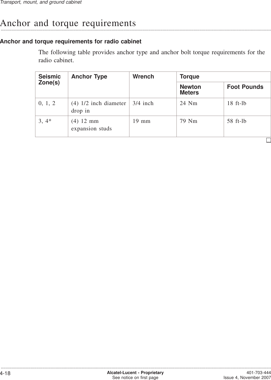
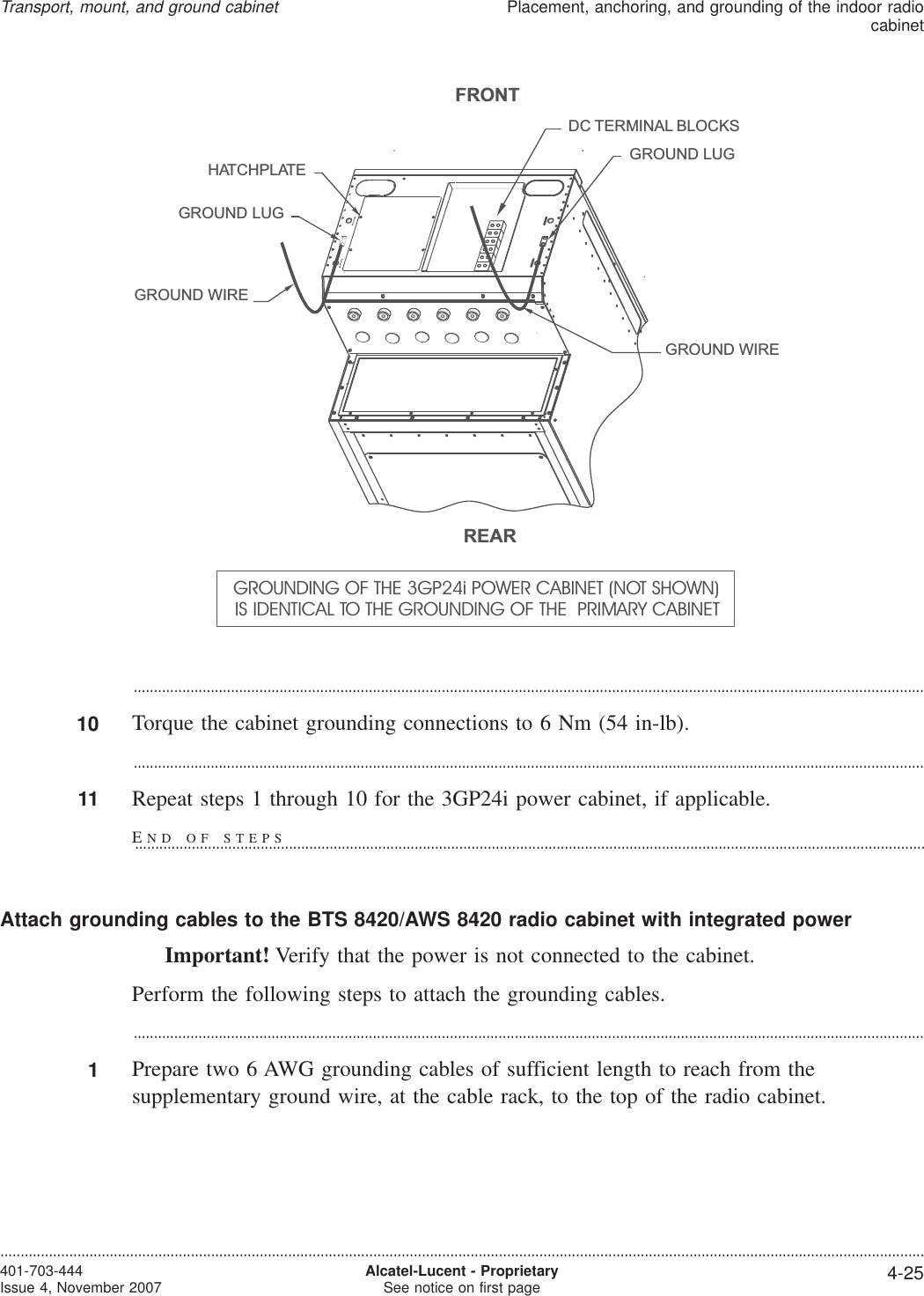
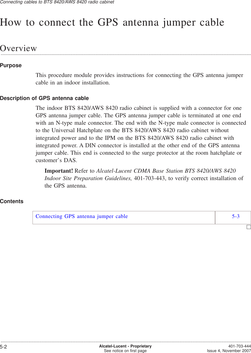
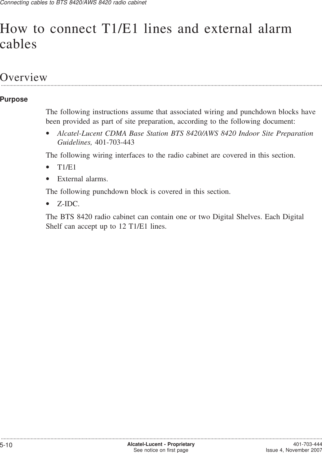
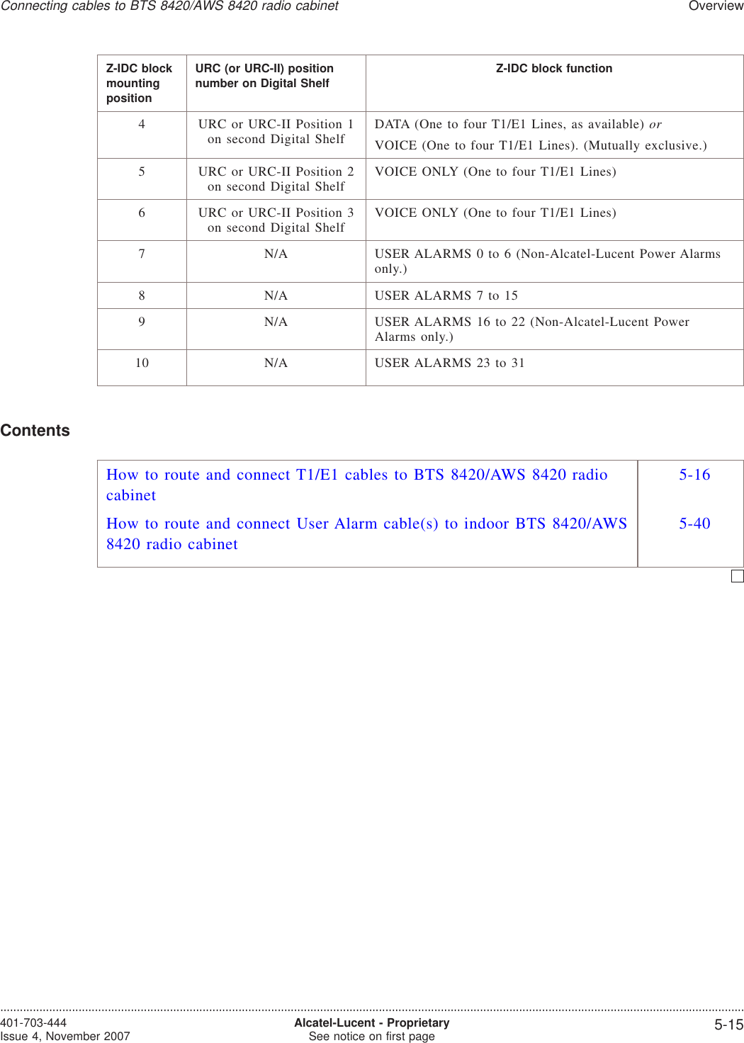
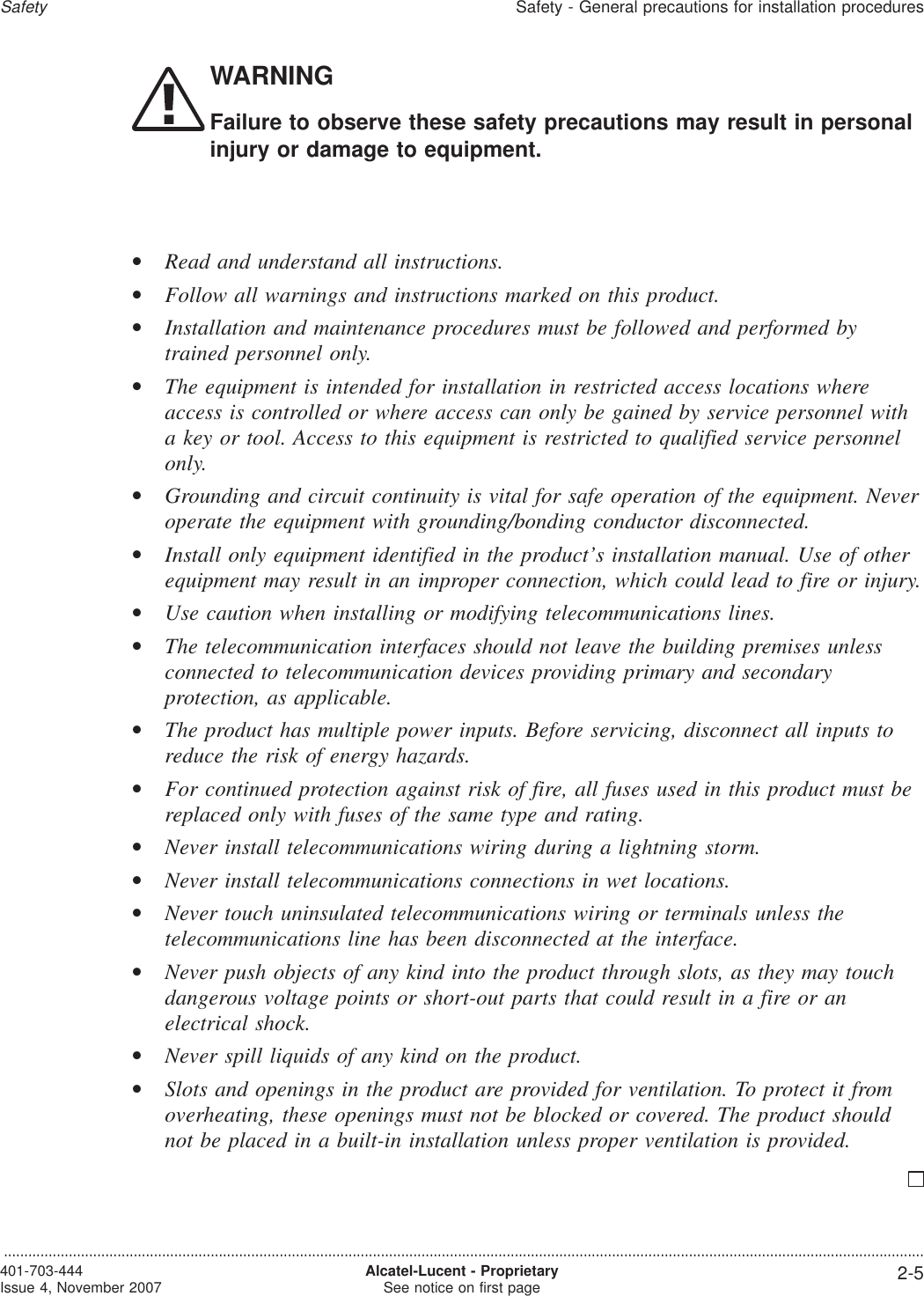
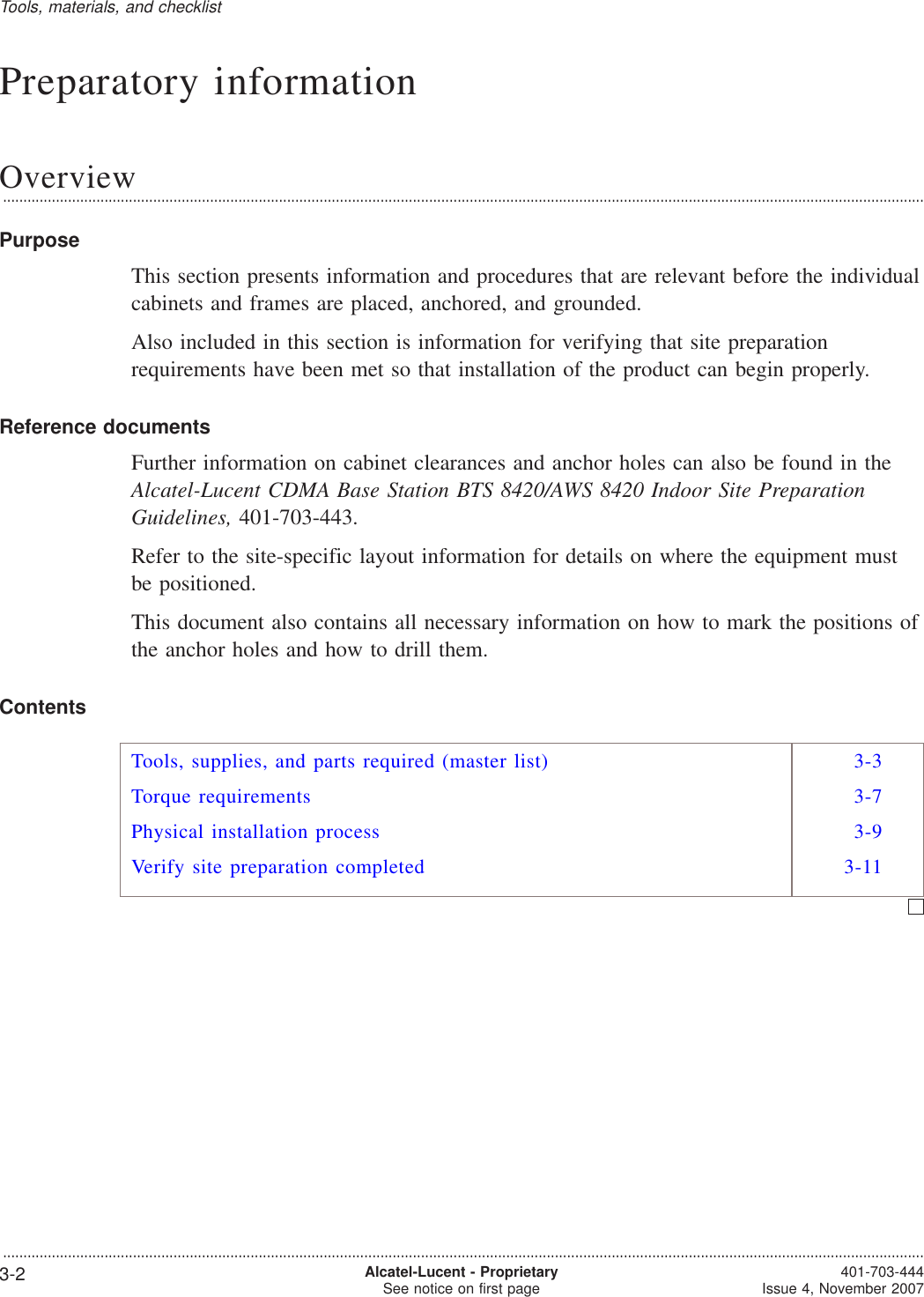
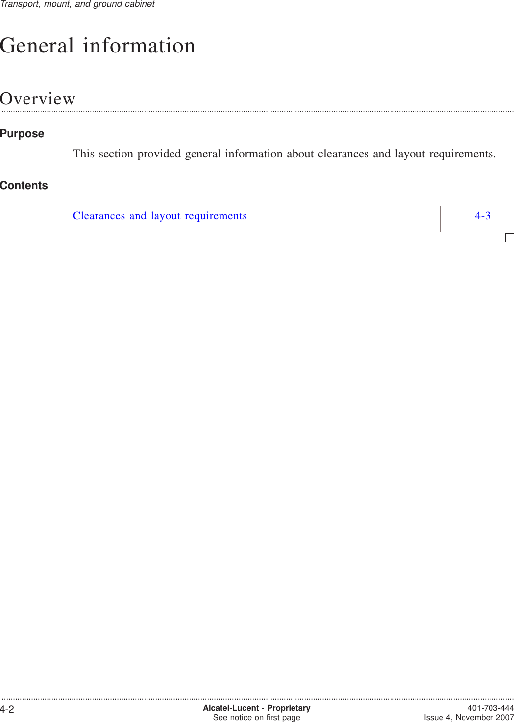
![MetricScrewSizeSAEScrewSizeTorque - in-lb [or ft-lb] and (Nm)Wire Connections Head Tightened Nut TightenedSlottedMachine Hex orSocketCapSlottedMachine Hex orSocketCapSlottedMachine Hex orSocketCapM6 1/4-20 50 (5.6) 50 (5.6) 65 (7.3) 65 (7.3) 65 (7.3) 80 (9.0)M8* 5/16-18 - 100 (11.3) - 135 (15.3) 135 (15.3) 165 (18.6)M10 3/8-16 - 180 (20.3) - 240 (27.1) 240 (27.1) 290 (32.8)M12 7/16-14 - 280 (31.6) - 385 (43.5) 385 (43.5) 465 (52.5)M14 1/2-13 - 500 (56.5) - 585 (66.1) 585 (66.1) 710 (80.2)M16 5/8-11 - [71](96.3)- [97](131.5)[97](131.5)[118](160.0)M20 3/4-10 - [125](169.5)- [172](233.2)[172](233.2)[209](283.4)Notes:1. *Do not use 7.3 Nm (65 in-lb) or 9.0 Nm (80 in-lb) for battery connections. Use the value given inChapter 5 for the appropriate battery.Torque requirements for terminal blocksThe table below provides torque requirements for the terminal blocks on the radiocabinet.Terminal block Minimum torque Nm(in-lb) Maximum torque Nm(in-lb)AC terminal block 1.5 (13.1) 1.8 (15.8)DC terminal block 3.2 (28) 3.7(32.4 )Tools, materials, and checklistTorque requirements....................................................................................................................................................................................................................................3-8 Alcatel-Lucent - ProprietarySee notice on first page 401-703-444Issue 4, November 2007](https://usermanual.wiki/Nokia-of-America/ONEBTS-23.USERS-MANUAL-2/User-Guide-975664-Page-21.png)
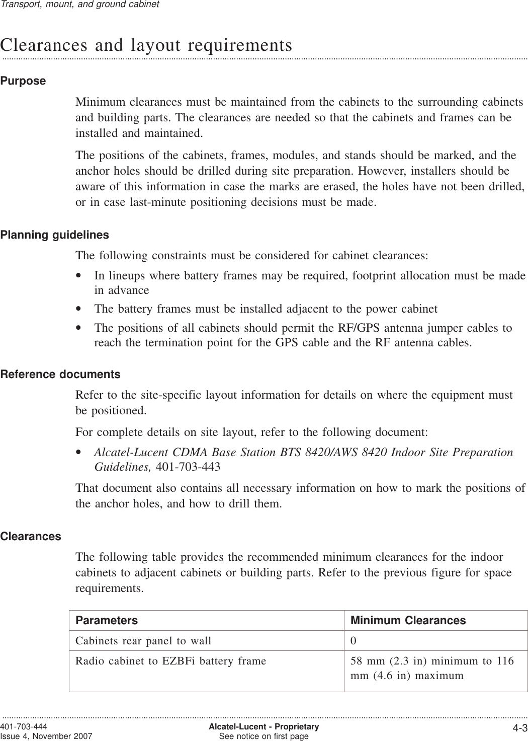
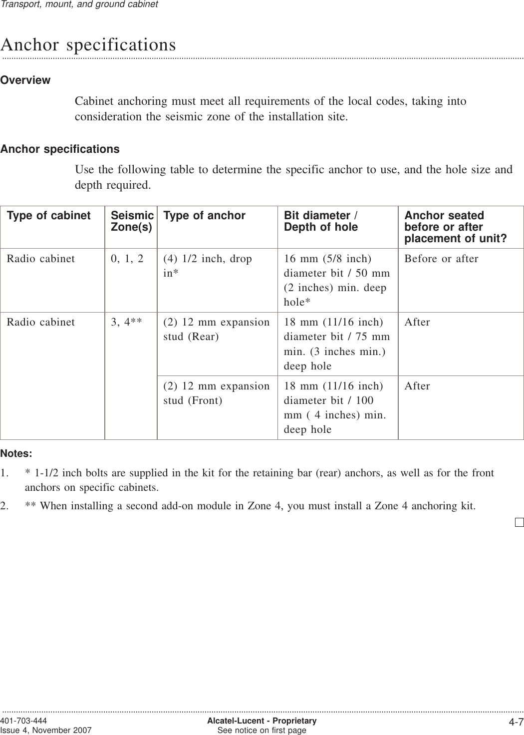
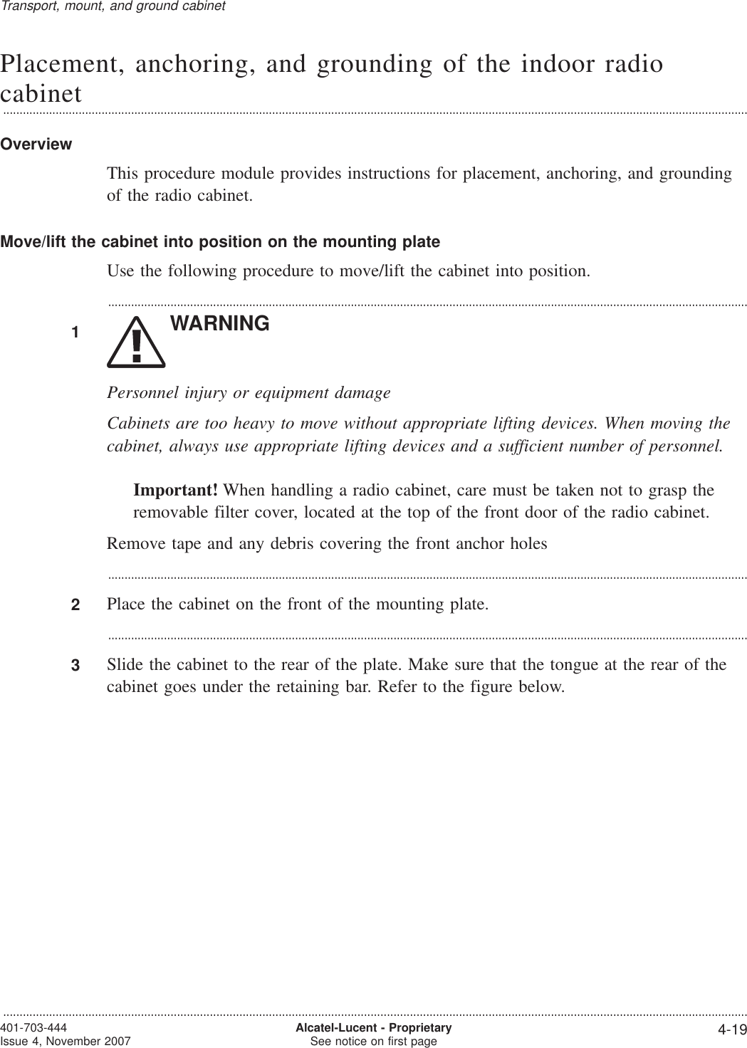
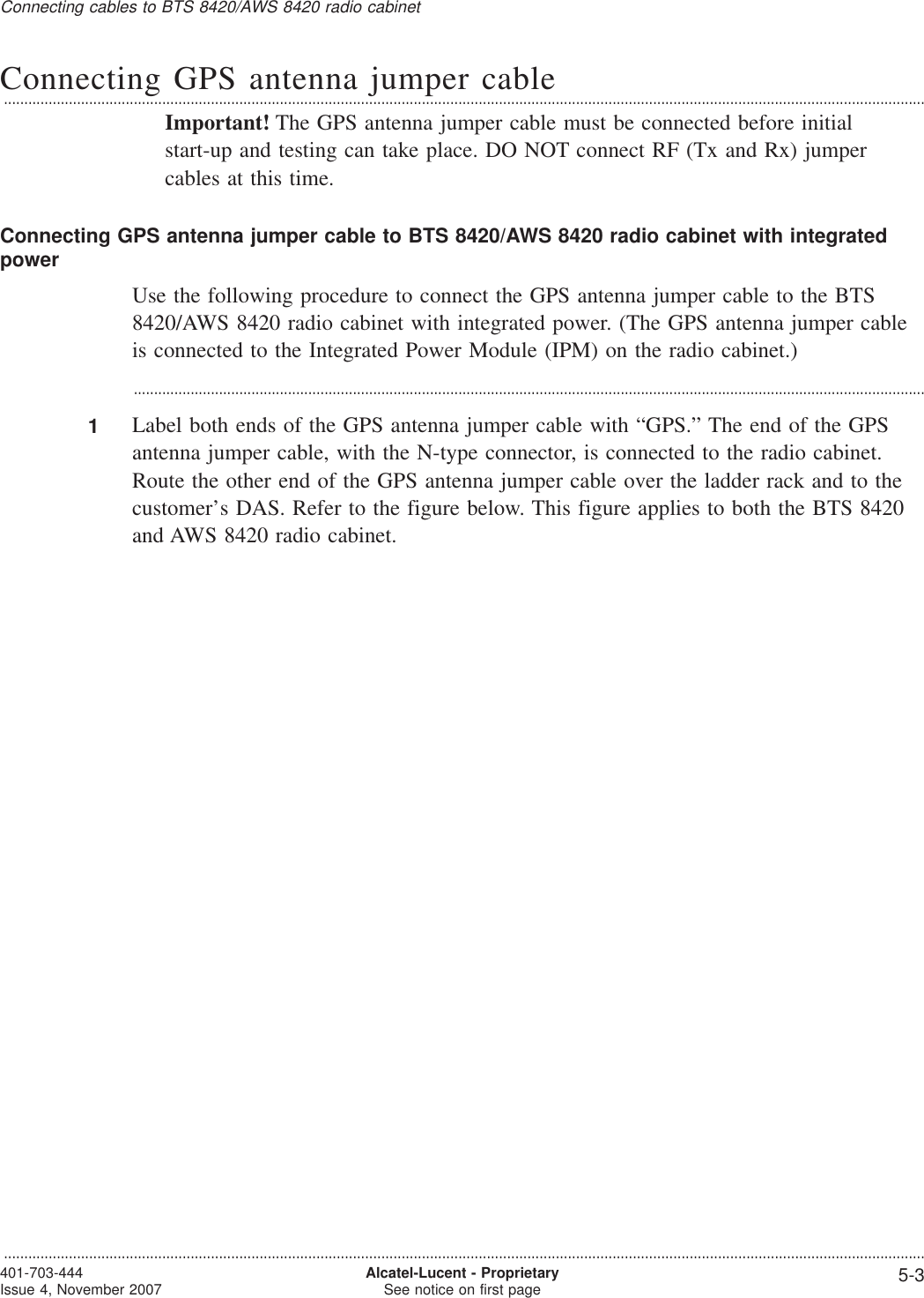
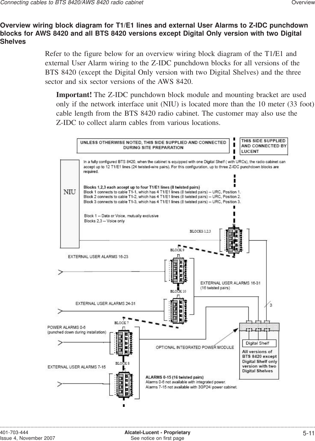
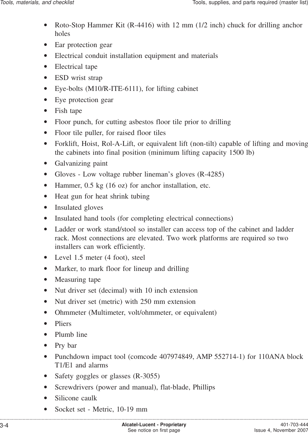
![How to prepare for cabinet or frame placementOverview...................................................................................................................................................................................................................................PurposeThis section shows how to determine anchor requirements, drill anchor holes, installradio cabinet mounting plates, and preset certain anchors, if applicable.[If anchor holes were not been drilled in site preparation, they should be drilled nowfor all radio cabinets, power frames, and battery stands during installation.]Power frame and battery stands require that seismic Zone 0-1 and 2-3 anchors bepreset before placement of the frame or stand instead of installing anchors afterplacement of the frame or stand.WARNINGHazards to ears, eyes, hands, and feetThe noise of a drill can damage hearing. The moving parts of a drill can damage thebody, especially the hands and eyes. The use of a drill can raise dust and small objectsthat may be hazardous. The use of a drill can also damage the legs and feet.Wear safety gloves, safety shoes, ear protection, and eye protection when using a drill.ContentsAnchor specifications 4-7How to drill anchor holes and install the mounting plate for BTS8420/AWS 8420 radio cabinet4-8Lifting and moving cabinets 4-14Transport, mount, and ground cabinet...................................................................................................................................................................................................................................4-6 Alcatel-Lucent - ProprietarySee notice on first page 401-703-444Issue 4, November 2007](https://usermanual.wiki/Nokia-of-America/ONEBTS-23.USERS-MANUAL-2/User-Guide-975664-Page-31.png)