Nokia of America ONEBTS-23 AWS DIGITAL HOST WIRELESS BASE STATION User Manual USERS MANUAL 2
Alcatel-Lucent USA Inc. AWS DIGITAL HOST WIRELESS BASE STATION USERS MANUAL 2
Contents
- 1. USERS MANUAL 1
- 2. USERS MANUAL 2
- 3. USERS MANUAL 3
- 4. USERS MANUAL 4
USERS MANUAL 2

22Safety
Overview
...................................................................................................................................................................................................................................
Purpose
This chapter presents the safety precautions that apply to the product.
In regions such as North America and the European Union, the statements that are
required are determined primarily by national or multinational regulations. However, in
some regions, contract terms determine which statements are required.
The presence of the statement indicates that the product does comply with that
statement wherever it is required to do so.
Contents
Structure of hazard statements 2-2
Safety - General precautions for installation procedures 2-4
Safety - specific hazards 2-6
Product safety 2-9
Safety labels on cabinet 2-10
...................................................................................................................................................................................................................................
401-703-444
Issue 4, November 2007 Alcatel-Lucent - Proprietary
See notice on first page 2-1
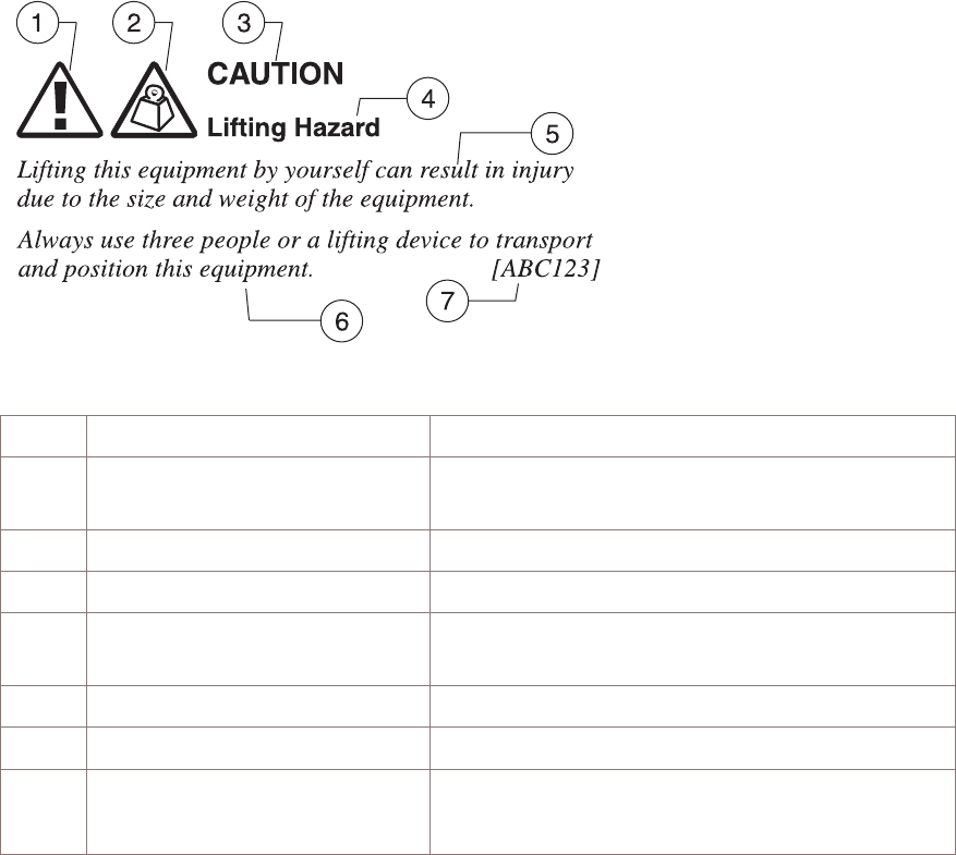
Structure of hazard statements
...................................................................................................................................................................................................................................
Overview
Hazard statements describe the safety risks relevant while performing tasks on
Alcatel-Lucent products during deployment and/or use. Failure to avoid the hazards
may have serious consequences.
General structure
Hazard statements include the following structural elements:
Item Structure element Purpose
1 Personal-injury symbol Indicates the potential for personal injury
(optional)
2 Hazard-type symbol Indicates hazard type (optional)
3 Signal word Indicates the severity of the hazard
4 Hazard type Describes the source of the risk of damage or
injury
5 Damage statement Consequences if protective measures fail
6 Avoidance message Protective measures to take to avoid the hazard
7 Identifier The reference ID of the hazard statement
(optional)
Safety
...................................................................................................................................................................................................................................
2-2 Alcatel-Lucent - Proprietary
See notice on first page 401-703-444
Issue 4, November 2007

Signal words
The signal words identify the hazard severity levels as follows:
Signal word Meaning
DANGER Indicates an imminently hazardous situation (high risk) which, if
not avoided, will result in death or serious injury.
WARNING Indicates a potentially hazardous situation (medium risk) which,
if not avoided, could result in death or serious injury.
CAUTION When used with the personal injury symbol:
Indicates a potentially hazardous situation (low risk) which, if
not avoided, may result in personal injury.
When used without the personal injury symbol:
Indicates a potentially hazardous situation (low risk) which, if
not avoided, may result in property damage, such as service
interruption or damage to equipment or other materials.
Within this IP, the safety label typically includes additional information such as the
hazard type, a description of the damage that can be caused, and the steps that should
be taken to avoid the hazard.
Safety
Structure of hazard statements
...................................................................................................................................................................................................................................
401-703-444
Issue 4, November 2007 Alcatel-Lucent - Proprietary
See notice on first page 2-3
Safety - General precautions for installation procedures
...................................................................................................................................................................................................................................
Overview
This topic reviews general precautions for installation.
Safety
...................................................................................................................................................................................................................................
2-4 Alcatel-Lucent - Proprietary
See notice on first page 401-703-444
Issue 4, November 2007

WARNING
Failure to observe these safety precautions may result in personal
injury or damage to equipment.
•Read and understand all instructions.
•Follow all warnings and instructions marked on this product.
•Installation and maintenance procedures must be followed and performed by
trained personnel only.
•The equipment is intended for installation in restricted access locations where
access is controlled or where access can only be gained by service personnel with
a key or tool. Access to this equipment is restricted to qualified service personnel
only.
•Grounding and circuit continuity is vital for safe operation of the equipment. Never
operate the equipment with grounding/bonding conductor disconnected.
•Install only equipment identified in the product’s installation manual. Use of other
equipment may result in an improper connection, which could lead to fire or injury.
•Use caution when installing or modifying telecommunications lines.
•The telecommunication interfaces should not leave the building premises unless
connected to telecommunication devices providing primary and secondary
protection, as applicable.
•The product has multiple power inputs. Before servicing, disconnect all inputs to
reduce the risk of energy hazards.
•For continued protection against risk of fire, all fuses used in this product must be
replaced only with fuses of the same type and rating.
•Never install telecommunications wiring during a lightning storm.
•Never install telecommunications connections in wet locations.
•Never touch uninsulated telecommunications wiring or terminals unless the
telecommunications line has been disconnected at the interface.
•Never push objects of any kind into the product through slots, as they may touch
dangerous voltage points or short-out parts that could result in a fire or an
electrical shock.
•Never spill liquids of any kind on the product.
•Slots and openings in the product are provided for ventilation. To protect it from
overheating, these openings must not be blocked or covered. The product should
not be placed in a built-in installation unless proper ventilation is provided.
Safety
Safety - General precautions for installation procedures
...................................................................................................................................................................................................................................
401-703-444
Issue 4, November 2007 Alcatel-Lucent - Proprietary
See notice on first page 2-5

Safety - specific hazards
...................................................................................................................................................................................................................................
Overview
This topic reviews specific hazards for installation.
DANGER
Lightning Strikes!
Lightning strikes are possible during stormy weather, and could result in death or
severe injury.
Do not work on the installation itself, or on the power supply lines, or antenna feeders
of a BTS 8420 radio cabinet during stormy weather.
WARNING
Energy Hazard!
Some parts of all electrical installations are energized. Failure to observe this fact and
the safety warnings may lead to bodily injury and property damage.
For this reason, only trained and qualified personnel may install or service the
installation.
WARNING
Energy Hazard!
The power supply lines to the network element are energized. Short circuits can cause
burns to the face and hands.
Open the load disconnect switch in the distribution box to completely de-energize the
network element.
Safety
...................................................................................................................................................................................................................................
2-6 Alcatel-Lucent - Proprietary
See notice on first page 401-703-444
Issue 4, November 2007

WARNING
Beryllium Oxide Poisoning Hazard!
The transmitter units include components which contain beryllium oxide (BeO). In this
form, BeO ceramics do not constitute a hazardous material as long as this material is
not destroyed by external mechanical forces.
In the event that repair work is carried out by the customer or by third parties, the
following regulations must be observed:
•Applicable version of the Regulation on Hazardous Materials in the Workplace
•Appropriate accident prevention regulations.
The following must be specifically observed:
•Eating, drinking, and smoking are not permitted in workplaces where BeO ceramic
components are being worked on.
•Wash your hands carefully under running water after working with BeO ceramic
components.
If the following symptoms occur, contact a physician:
•Irritation of the respiratory organs
•Difficulty breathing or skin irritation.
CAUTION
Condensation may cause a short circuit!
Sudden changes in the weather may lead to the formation of condensation on
components. Operating the unit when condensation moisture is present can destroy the
unit.
Units which show signs of condensation must be dried before installation.
Safety
Safety - specific hazards
...................................................................................................................................................................................................................................
401-703-444
Issue 4, November 2007 Alcatel-Lucent - Proprietary
See notice on first page 2-7

CAUTION
Electrostatically Sensitive Components!
Semiconductor elements can be damaged by static discharges.
The following rules must be complied with when handling any module containing
semiconductor components:
•Wear conductive or antistatic work clothes (for example, coat made of 100%
cotton).
•Wear grounded ESD wrist strap.
•Wear shoes with conductive soles.
•Leave the modules in their original packaging until ready for use.
•Make sure there is no difference in potential between yourself, the workplace, and
the package before removing, unpacking, or packing a module.
•Hold the module only by the grip without touching the connection pins, tracks, or
components.
•Place modules removed from the equipment on a conductive surface.
•Test or handle the module only with grounded tools on grounded equipment.
•Handle defective modules exactly like new ones to avoid causing further damage.
Safety
Safety - specific hazards
...................................................................................................................................................................................................................................
2-8 Alcatel-Lucent - Proprietary
See notice on first page 401-703-444
Issue 4, November 2007

Product safety
...................................................................................................................................................................................................................................
Compliance statement
The BTS 8420/AWS 8420 is UL Listed, Information Technology Equipment. The UL
Listing applies to both the USA and Canada and is Marked on the Equipment main
nameplate label. Should the local Authority Having Jurisdiction (AHJ) require prior or
additional verification of this Listing, a Product Certificate of Compliance from
Underwriters Laboratories can be obtained by contacting the Alcatel-Lucent Global
Product Compliance Laboratory located at 600-700 Mountain Avenue, Murray Hill, NJ
07974. Any modifications to this equipment are not permitted without review and
official authorization from the Alcatel-Lucent Global Product Compliance Laboratory.
Modifications or changes authorized by official CN/CNN are assumed to have received
prior approval from this Lab.
Equipment safety
Safety information for this equipment can be found on various Caution, Warning,
Danger, information labels or instructions affixed to or included with the BTS
8420/AWS 8420, its internal assemblies or included within this document.
Informational and cautionary labels may appear near the item they address or may be
grouped in a single location on the equipment. Warnings are typically adjacent to the
hazard that is noted on the label. The instructions, cautions and warnings found on
these labels must be understood and observed by all personnel involved with the
equipment installation and maintenance.
This equipment is to be installed in accordance with all National, State (Provincial),
and Local Safety Codes for the US and Canada, and National Laws, Codes, etc. for
other countries. All AC/DC powered equipments MUST BE properly grounded, in
accordance with theses codes.
Important! Refer to the ″Specific -- safety hazards″section for definitions of
safety labels.
Safety
...................................................................................................................................................................................................................................
401-703-444
Issue 4, November 2007 Alcatel-Lucent - Proprietary
See notice on first page 2-9
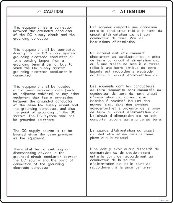
Safety labels on cabinet
...................................................................................................................................................................................................................................
Overview
This section illustrates the safety labels, which are located on the BTS 8420/AWS 8420
radio cabinet.
Safety labels on BTS 8420/AWS 8420 radio cabinet
GROUNDING CAUTION
EXTERNAL ALARM PROTECTION WARNING
Safety
...................................................................................................................................................................................................................................
2-10 Alcatel-Lucent - Proprietary
See notice on first page 401-703-444
Issue 4, November 2007
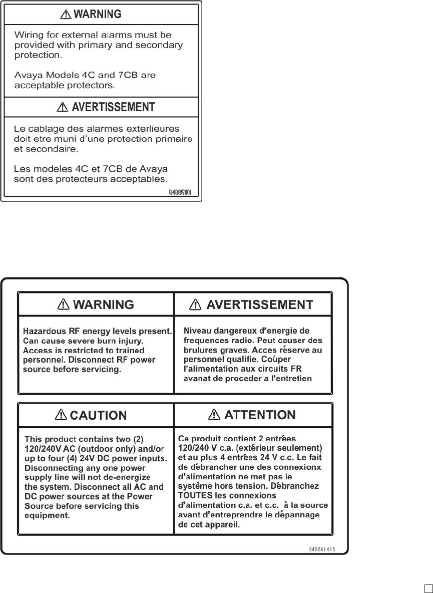
RF ENERGY WARNING AND +24 VDC POWER CAUTION
The following label is present only on +24 VDC radio cabinets.
Safety
Safety labels on cabinet
...................................................................................................................................................................................................................................
401-703-444
Issue 4, November 2007 Alcatel-Lucent - Proprietary
See notice on first page 2-11

33Tools, materials, and checklist
Overview
...................................................................................................................................................................................................................................
Purpose
This chapter provides general instructions for anchor installation and cabinet handling.
Also included are the procedures for cabinet placement, anchoring, and grounding.
Contents
Preparatory information 3-2
Tools, supplies, and parts required (master list) 3-3
Torque requirements 3-7
Physical installation process 3-9
Verify site preparation completed 3-11
...................................................................................................................................................................................................................................
401-703-444
Issue 4, November 2007 Alcatel-Lucent - Proprietary
See notice on first page 3-1

Preparatory information
Overview
...................................................................................................................................................................................................................................
Purpose
This section presents information and procedures that are relevant before the individual
cabinets and frames are placed, anchored, and grounded.
Also included in this section is information for verifying that site preparation
requirements have been met so that installation of the product can begin properly.
Reference documents
Further information on cabinet clearances and anchor holes can also be found in the
Alcatel-Lucent CDMA Base Station BTS 8420/AWS 8420 Indoor Site Preparation
Guidelines, 401-703-443.
Refer to the site-specific layout information for details on where the equipment must
be positioned.
This document also contains all necessary information on how to mark the positions of
the anchor holes and how to drill them.
Contents
Tools, supplies, and parts required (master list) 3-3
Torque requirements 3-7
Physical installation process 3-9
Verify site preparation completed 3-11
Tools, materials, and checklist
...................................................................................................................................................................................................................................
3-2 Alcatel-Lucent - Proprietary
See notice on first page 401-703-444
Issue 4, November 2007

Tools, supplies, and parts required (master list)
...................................................................................................................................................................................................................................
Overview
This section provides a master list of all tools, materials, and parts required to perform
the installation. If additional items are needed to perform a specific task, they are listed
in the applicable chapter.
Tools
CAUTION
Personnel injury or equipment damage
If the installation is performed with energized DC circuits, be sure to use tools that are
properly insulated.
The following is a master list, in alphabetical order, of all tools that may be utilized
during installation.
•Adjustable open-end wrench (or set of fixed open-end wrenches)
•Antioxidant compound
•B connecting links, or equivalent (quantity: 3)
•Bolt anchor setting tool
•Bonding clamps for facility and phone line cables (normally provided by telephone
company)
•Box cutter or equivalent, to open packaging
•Chalk line
•Channel-lock pliers [for 2-1/2 inch nuts, max. 19 mm (3/4 inch) wide]
•Channel-lock pliers (standard)
•Crimping tools, 5-120 mm2 (22-16 and 10-4/0 AWG), for installation of terminal
lugs and C-Taps
•Derrick, capable of lifting 680-kg (1500 lb)
•DIN connector stripping tool: part numbers
•For Huber Suhner cable/connector: 74Z-0-12-15
•For Andrew cable/connectors: ITE-7189
•For RFS cable/connectors: TRIM-L12-A
•Drill and drill bits [including 16 mm (5/8 inch) and 18 mm (11/16 inch) for drilling
anchor holes)
•Drill - Pneumatic Hammer (R-5006)
Tools, materials, and checklist
...................................................................................................................................................................................................................................
401-703-444
Issue 4, November 2007 Alcatel-Lucent - Proprietary
See notice on first page 3-3
•Roto-Stop Hammer Kit (R-4416) with 12 mm (1/2 inch) chuck for drilling anchor
holes
•Ear protection gear
•Electrical conduit installation equipment and materials
•Electrical tape
•ESD wrist strap
•Eye-bolts (M10/R-ITE-6111), for lifting cabinet
•Eye protection gear
•Fish tape
•Floor punch, for cutting asbestos floor tile prior to drilling
•Floor tile puller, for raised floor tiles
•Forklift, Hoist, Rol-A-Lift, or equivalent lift (non-tilt) capable of lifting and moving
the cabinets into final position (minimum lifting capacity 1500 lb)
•Galvanizing paint
•Gloves - Low voltage rubber lineman’s gloves (R-4285)
•Hammer, 0.5 kg (16 oz) for anchor installation, etc.
•Heat gun for heat shrink tubing
•Insulated gloves
•Insulated hand tools (for completing electrical connections)
•Ladder or work stand/stool so installer can access top of the cabinet and ladder
rack. Most connections are elevated. Two work platforms are required so two
installers can work efficiently.
•Level 1.5 meter (4 foot), steel
•Marker, to mark floor for lineup and drilling
•Measuring tape
•Nut driver set (decimal) with 10 inch extension
•Nut driver set (metric) with 250 mm extension
•Ohmmeter (Multimeter, volt/ohmmeter, or equivalent)
•Pliers
•Plumb line
•Pry bar
•Punchdown impact tool (comcode 407974849, AMP 552714-1) for 110ANA block
T1/E1 and alarms
•Safety goggles or glasses (R-3055)
•Screwdrivers (power and manual), flat-blade, Phillips
•Silicone caulk
•Socket set - Metric, 10-19 mm
Tools, materials, and checklist
Tools, supplies, and parts required (master list)
....................................................................................................................................................................................................................................
3-4 Alcatel-Lucent - Proprietary
See notice on first page 401-703-444
Issue 4, November 2007
•Socket sets (decimal and metric) various drives
•Stripping tool (for LDF4 antenna jumper cables) part number 74Z-0-12-15
•Tools for preparing cables
•Torque wrenches, 4-34 Nm (35-300 in-lb)
•Torque wrenches, 6-200 Nm (4.4-150 ft-lb)
•Vacuum cleaner or equivalent, as required for clearing debris from anchor holes
•Wire cutter (capable of cutting up to 1/0 AWG)
•Wire stripper
•Wire rope slings, 11 mm (7/16 inch), 2 meters (7 feet) long, minimum (quantity: 2)
•Wrench - Adjustable, 20 mm (3/4 inch) open-end wrench (or set of fixed open-end
wrenches)
•Wrench - Flare Nut or Box Wrench, 12 mm (1/2 inch), required for installing
seismic anchors.
•Z-IDC punchdown tool: ITE No. R-6097 (KRONE).
Supplies needed
The following is an alphabetical master list of all supplies that are required for
installation of the various cabinets, frames and stands.
•Antioxidant compound (provided)
•Lacing cord, waxed #50 or cable ties
•Red tape or tags - 145C or equivalent, for tagging DC power cables
•Shims for leveling and final placement of cabinet (some are provided with
anchoring kit)
•Tags - 145C or equivalent, for tagging DC power cables
•Tape - Electrical tape
•Tape - Masking tape, for protecting open anchor holes
•Tie wraps
•Eyebolt tool (M10/R-ITE-6111)
•Twine.
Parts and/or kits needed
The following is a master list of all parts and kits that are required for installation of
the various cabinets, frames and stands.
For Base Station 8420 radio cabinets:
•External user alarm interface kit
•GPS antenna jumper cable
•RF antenna jumper cables.
Tools, materials, and checklist
Tools, supplies, and parts required (master list)
....................................................................................................................................................................................................................................
401-703-444
Issue 4, November 2007 Alcatel-Lucent - Proprietary
See notice on first page 3-5

•Anchor kit - type as required per earthquake zone
•T1/E1 interface kit
•DC cable kit, 1/0 AWG (one feed, one return) - Quantity: 1.
For the first or second EZBFi battery frame:
•Anchor kit - Quantity as required per earthquake zone
•Batteries - Quantity as required per site specification. Batteries include
interconnecting bars and connecting hardware
•Battery frame DC feeder cable kit(s).
Tools, materials, and checklist
Tools, supplies, and parts required (master list)
....................................................................................................................................................................................................................................
3-6 Alcatel-Lucent - Proprietary
See notice on first page 401-703-444
Issue 4, November 2007

Torque requirements
...................................................................................................................................................................................................................................
Overview
This section provides mechanical torque requirements. Refer to the table below.
Torque requirements for mechanical connections
The table below identifies the torque requirements to be followed when making
mechanical connections.
Item Description Torque
Newton
Meters Inch Pounds
Antenna jumper cable connections (7/16 inch DIN) 25 221
GPS antenna jumper cable connection (N) at radio
cabinet
1.7 15
GPS antenna jumper cable connection (DIN) at
room hatchplate
25 221
M6 x 16 mm thread rolling screw 4 30
All other M6 fasteners (nuts, hex-head bolts, etc.) 4 30
All M5 fasteners (pan-head screws, hex nut, etc.) 4 30
All M4 fasteners (pan-head screws, hex nut, etc.) 1.5 14
Generic torque requirements for electrical connections
Important! The table below must not be used for spanner head self-tapping screws,
in or on cabinets. It is to be used exclusively for electrical connections. Refer to
the previous table for mechanical connections.
The table below identifies the torque requirements to be followed when making
electrical connections.
Metric
Screw
Size
SAE
Screw
Size
Torque - in-lb [or ft-lb] and (Nm)
Wire Connections Head Tightened Nut Tightened
Slotted
Machine Hex or
Socket
Cap
Slotted
Machine Hex or
Socket
Cap
Slotted
Machine Hex or
Socket
Cap
M4 8-32 15 (1.7) 15 (1.7) 19 (2.1) 19 (2.1) 19 (2.1) 23 (2.6)
M5 10-24 21 (2.4) 21 (2.4) 27 (3.1) 27 (3.1) 27 (3.1) 33 (3.7)
Tools, materials, and checklist
...................................................................................................................................................................................................................................
401-703-444
Issue 4, November 2007 Alcatel-Lucent - Proprietary
See notice on first page 3-7

Metric
Screw
Size
SAE
Screw
Size
Torque - in-lb [or ft-lb] and (Nm)
Wire Connections Head Tightened Nut Tightened
Slotted
Machine Hex or
Socket
Cap
Slotted
Machine Hex or
Socket
Cap
Slotted
Machine Hex or
Socket
Cap
M6 1/4-20 50 (5.6) 50 (5.6) 65 (7.3) 65 (7.3) 65 (7.3) 80 (9.0)
M8* 5/16-18 - 100 (11.3) - 135 (15.3) 135 (15.3) 165 (18.6)
M10 3/8-16 - 180 (20.3) - 240 (27.1) 240 (27.1) 290 (32.8)
M12 7/16-14 - 280 (31.6) - 385 (43.5) 385 (43.5) 465 (52.5)
M14 1/2-13 - 500 (56.5) - 585 (66.1) 585 (66.1) 710 (80.2)
M16 5/8-11 - [71]
(96.3)
- [97]
(131.5)
[97]
(131.5)
[118]
(160.0)
M20 3/4-10 - [125]
(169.5)
- [172]
(233.2)
[172]
(233.2)
[209]
(283.4)
Notes:
1. *Do not use 7.3 Nm (65 in-lb) or 9.0 Nm (80 in-lb) for battery connections. Use the value given in
Chapter 5 for the appropriate battery.
Torque requirements for terminal blocks
The table below provides torque requirements for the terminal blocks on the radio
cabinet.
Terminal block Minimum torque Nm
(in-lb) Maximum torque Nm
(in-lb)
AC terminal block 1.5 (13.1) 1.8 (15.8)
DC terminal block 3.2 (28) 3.7(32.4 )
Tools, materials, and checklist
Torque requirements
....................................................................................................................................................................................................................................
3-8 Alcatel-Lucent - Proprietary
See notice on first page 401-703-444
Issue 4, November 2007
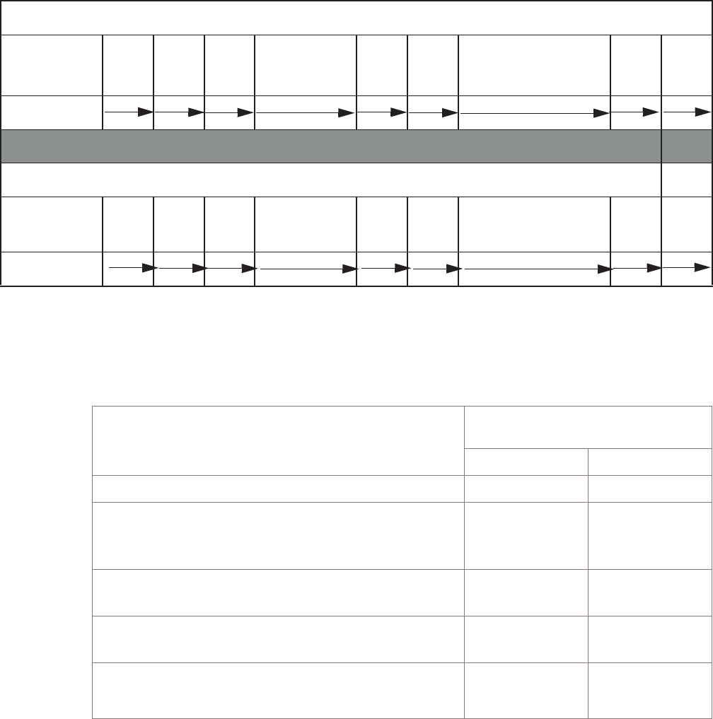
Physical installation process
...................................................................................................................................................................................................................................
Physical installation process chart
The chart shown below assigns the concurrent installation activities for each of two
installers. The specific activities are listed in the table that follows. The table represents
the activities required to install an indoor radio cabinet.
Physical installation process table
The following table assumes that two installers are working concurrently.
ACTIVITIES
INSTALLER ACTIVITY
ASSIGNMENT
INSTALLER 1 INSTALLER 2
1. Check parts inventory X
2. Place the BTS 8420 radio cabinet and 3GP24i
power cabinet mounting plates and anchor them
through the retaining bars at the rear
X
3. Place the BTS 8420 radio cabinet and 3GP24i
power cabinet on the mounting plates
XX
4. Anchor the front of the primary cabinet and
3GP24i power cabinet
X
5. Ground the BTS 8420 radio cabinet and 3GP24i
power cabinet
X
INSTALLER 1
ACTIVITY
NUMBER
#11 #12
INSTALLER 2
ACTIVITY
NUMBER
#2 #3 #5 #6 #9 #10 #11 #13 #15
Tools, materials, and checklist
...................................................................................................................................................................................................................................
401-703-444
Issue 4, November 2007 Alcatel-Lucent - Proprietary
See notice on first page 3-9

ACTIVITIES
INSTALLER ACTIVITY
ASSIGNMENT
INSTALLER 1 INSTALLER 2
6. Route six RF antenna cable jumpers and one
GPS antenna cable (connect GPS antenna jumper
cable only)
XX
7. Connect and route the T1/E1and user alarm
cables from the primary cabinet to the location of
the punchdown blocks
X
8. Punch down the T1/E1, user alarm and Power
Alarm cables to the punchdown blocks
X
9. Route the Power Alarm cable from the 3GP24i
power cabinet to the BTS 8420 radio cabinet and
connect it
X
10. Install rectifiers in the 3GP24i power cabinet X
11. Install the DC cables from the 3GP24i power
cabinet to the BTS 8420 radio cabinet and install
circuit breakers in the 3GP24i power cabinet
XX
12. Route and connect the AC feed to the 3GP24i
power cabinet
X
13. Clean up X
14. Turn on and check power X
15. Connect six RF antenna cable jumpers X
Tools, materials, and checklist
Physical installation process
....................................................................................................................................................................................................................................
3-10 Alcatel-Lucent - Proprietary
See notice on first page 401-703-444
Issue 4, November 2007

Verify site preparation completed
...................................................................................................................................................................................................................................
Overview
This topic describes what must be done to verify that the site preparation is complete
so that installation procedures can begin.
If some of the requirements are not met, the installer must do so now.
Verify site preparation
Before installation of the cabinet site can begin, site preparation should have been
completed in accordance with the Alcatel-Lucent CDMA Base Station BTS 8420/AWS
8420 Indoor Site Preparation Guidelines, 401-703-443
This unit is only to be installed in restricted access locations.
The following site preparation requirements must be met before the installation of the
cabinet can begin:
•Adequate clearance must be provided for service access.
•AC electric service must be installed as described later in the document.
•T1/E1 and user alarm facilities must be installed as described in later in the
document.
•Z-IDC punchdown blocks for indoor T1/E1 and User Alarm facilities must be
installed, as described later in this document.
•Balun Box must be installed (if required).
•Grounding system (supplementary ground for frame grounding; bus bar for CO
grounding) must be installed.
•RF and GPS antenna runs must be installed.
•Surge protection for antennas must be installed (if required).
•Tower light power must be installed (if required).
•Tower light alarm must be installed (if required).
•Cabinet anchor holes must be drilled.
•The environment must comply with limits listed on page 1-3 (indoor)
•Cable supports and racks must be installed (indoor).
•3/4 inch conduit for AC
•Cable supports and racks must be installed.
Tools, materials, and checklist
...................................................................................................................................................................................................................................
401-703-444
Issue 4, November 2007 Alcatel-Lucent - Proprietary
See notice on first page 3-11

44Transport, mount, and ground
cabinet
Overview
...................................................................................................................................................................................................................................
Purpose
This chapter provides general instructions for anchor installation and cabinet handling,
as well as cabinet placement, anchoring and grounding. Included are instructions for all
indoor cabinets, including the EZBFi battery base modules.
Important! These units are only to be installed in restricted access locations.
Contents
General information 4-2
Clearances and layout requirements 4-3
How to prepare for cabinet or frame placement 4-6
Anchor specifications 4-7
How to drill anchor holes and install the mounting plate for BTS
8420/AWS 8420 radio cabinet
4-8
Lifting and moving cabinets 4-14
How to place, anchor, and ground cabinets, frames, or stands 4-17
Anchor and torque requirements 4-18
Placement, anchoring, and grounding of the indoor radio cabinet 4-19
...................................................................................................................................................................................................................................
401-703-444
Issue 4, November 2007 Alcatel-Lucent - Proprietary
See notice on first page 4-1

General information
Overview
...................................................................................................................................................................................................................................
Purpose
This section provided general information about clearances and layout requirements.
Contents
Clearances and layout requirements 4-3
Transport, mount, and ground cabinet
...................................................................................................................................................................................................................................
4-2 Alcatel-Lucent - Proprietary
See notice on first page 401-703-444
Issue 4, November 2007

Clearances and layout requirements
...................................................................................................................................................................................................................................
Purpose
Minimum clearances must be maintained from the cabinets to the surrounding cabinets
and building parts. The clearances are needed so that the cabinets and frames can be
installed and maintained.
The positions of the cabinets, frames, modules, and stands should be marked, and the
anchor holes should be drilled during site preparation. However, installers should be
aware of this information in case the marks are erased, the holes have not been drilled,
or in case last-minute positioning decisions must be made.
Planning guidelines
The following constraints must be considered for cabinet clearances:
•In lineups where battery frames may be required, footprint allocation must be made
in advance
•The battery frames must be installed adjacent to the power cabinet
•The positions of all cabinets should permit the RF/GPS antenna jumper cables to
reach the termination point for the GPS cable and the RF antenna cables.
Reference documents
Refer to the site-specific layout information for details on where the equipment must
be positioned.
For complete details on site layout, refer to the following document:
•Alcatel-Lucent CDMA Base Station BTS 8420/AWS 8420 Indoor Site Preparation
Guidelines, 401-703-443
That document also contains all necessary information on how to mark the positions of
the anchor holes, and how to drill them.
Clearances
The following table provides the recommended minimum clearances for the indoor
cabinets to adjacent cabinets or building parts. Refer to the previous figure for space
requirements.
Parameters Minimum Clearances
Cabinets rear panel to wall 0
Radio cabinet to EZBFi battery frame 58 mm (2.3 in) minimum to 116
mm (4.6 in) maximum
Transport, mount, and ground cabinet
...................................................................................................................................................................................................................................
401-703-444
Issue 4, November 2007 Alcatel-Lucent - Proprietary
See notice on first page 4-3

Parameters Minimum Clearances
First EZBFi battery frame to second EZBFi battery
frame
58 mm (2.3 in) minimum to 116
mm (4.6 in) maximum
EZBFi battery frame right side panel to wall 0 (if no second battery frame
planned). Some clearance
recommended.
In front of the cabinet (for installation and service
access)
914 mm (36 in)
Side of radio cabinet to other cabinets, as
applicable
0
Radio cabinet right side panel to wall (door open
90 degrees).
152.4 mm (6 in)
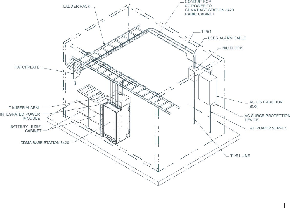
Layouts - indoor
Refer to the following figure for a typical installation of the BTS 8420 radio cabinet.
The figure below shows a BTS 8420 radio cabinet next to two EZBFi frames.
Transport, mount, and ground cabinet
Clearances and layout requirements
....................................................................................................................................................................................................................................
4-4 Alcatel-Lucent - Proprietary
See notice on first page 401-703-444
Issue 4, November 2007
Transport, mount, and ground cabinet
Clearances and layout requirements
....................................................................................................................................................................................................................................
401-703-444
Issue 4, November 2007 Alcatel-Lucent - Proprietary
See notice on first page 4-5

How to prepare for cabinet or frame placement
Overview
...................................................................................................................................................................................................................................
Purpose
This section shows how to determine anchor requirements, drill anchor holes, install
radio cabinet mounting plates, and preset certain anchors, if applicable.
[If anchor holes were not been drilled in site preparation, they should be drilled now
for all radio cabinets, power frames, and battery stands during installation.]
Power frame and battery stands require that seismic Zone 0-1 and 2-3 anchors be
preset before placement of the frame or stand instead of installing anchors after
placement of the frame or stand.
WARNING
Hazards to ears, eyes, hands, and feet
The noise of a drill can damage hearing. The moving parts of a drill can damage the
body, especially the hands and eyes. The use of a drill can raise dust and small objects
that may be hazardous. The use of a drill can also damage the legs and feet.
Wear safety gloves, safety shoes, ear protection, and eye protection when using a drill.
Contents
Anchor specifications 4-7
How to drill anchor holes and install the mounting plate for BTS
8420/AWS 8420 radio cabinet
4-8
Lifting and moving cabinets 4-14
Transport, mount, and ground cabinet
...................................................................................................................................................................................................................................
4-6 Alcatel-Lucent - Proprietary
See notice on first page 401-703-444
Issue 4, November 2007

Anchor specifications
...................................................................................................................................................................................................................................
Overview
Cabinet anchoring must meet all requirements of the local codes, taking into
consideration the seismic zone of the installation site.
Anchor specifications
Use the following table to determine the specific anchor to use, and the hole size and
depth required.
Type of cabinet Seismic
Zone(s) Type of anchor Bit diameter /
Depth of hole Anchor seated
before or after
placement of unit?
Radio cabinet 0, 1, 2 (4) 1/2 inch, drop
in*
16 mm (5/8 inch)
diameter bit / 50 mm
(2 inches) min. deep
hole*
Before or after
Radio cabinet 3, 4** (2) 12 mm expansion
stud (Rear)
18 mm (11/16 inch)
diameter bit / 75 mm
min. (3 inches min.)
deep hole
After
(2) 12 mm expansion
stud (Front)
18 mm (11/16 inch)
diameter bit / 100
mm ( 4 inches) min.
deep hole
After
Notes:
1. * 1-1/2 inch bolts are supplied in the kit for the retaining bar (rear) anchors, as well as for the front
anchors on specific cabinets.
2. ** When installing a second add-on module in Zone 4, you must install a Zone 4 anchoring kit.
Transport, mount, and ground cabinet
...................................................................................................................................................................................................................................
401-703-444
Issue 4, November 2007 Alcatel-Lucent - Proprietary
See notice on first page 4-7
How to drill anchor holes and install the mounting plate for
BTS 8420/AWS 8420 radio cabinet
...................................................................................................................................................................................................................................
Overview
This section provides instructions for the installation of mounting plates for the radio
cabinet. Also included are instructions for marking and drilling anchor holes, if the
holes were not drilled during site preparation.
Note that indoor cabinets/frames may be mounted directly on a concrete pad.
Procedures for the preparation of other types of mounting surfaces are the
responsibility of the customer.
Important! Radio cabinets that are equipped with an integrated power module (or
that are going to be subsequently equipped with an integrated power module)
cannot be installed with zero clearance to a wall. Access to the rear of the cabinet
must be provided.
Before you begin
If anchor holes have been drilled during site preparation, skip to “Place and level the
mounting plate and torque the rear anchors” (p. 4-10) to continue the installation.
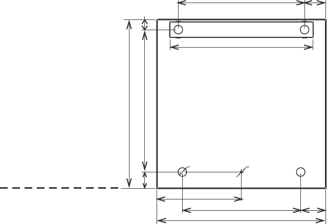
Position the BTS 8420/AWS 8420 radio cabinet mounting plate for anchor hole marking
To position the radio cabinet mounting plate, perform the following steps:
...................................................................................................................................................................................................
1Check that the floor is free of debris and is properly marked with the front edge
footprint of the cabinet to be installed. Also check that when the cabinet(s) are
subsequently mounted in position, there will be adequate surrounding clearance. See
“Layouts - indoor” (p. 4-4).
Important! When performing the next step, note that there is a small (5 mm) hole
along the front edge of the mounting plate. Also, the anchor holes in the rear of the
mounting plate are farther apart than the anchor holes in the front of the mounting
plate.
...................................................................................................................................................................................................
2Rotate the mounting plate as needed until it is oriented correctly.
...................................................................................................................................................................................................
3Position the mounting plate with the front edge of the mounting plate on the front line
of the lineup. Refer to the figure below.
Transport, mount, and ground cabinet
...................................................................................................................................................................................................................................
4-8 Alcatel-Lucent - Proprietary
See notice on first page 401-703-444
Issue 4, November 2007
...................................................................................................................................................................................................
4Proceed to the next page to mark and drill the anchor holes.
Mark and drill the anchor holes (if required)
If the anchor holes were not drilled during site preparation, perform the following steps
to mark and drill the anchor holes.
...................................................................................................................................................................................................
1Mark the anchor hole locations through the holes of the mounting plate(s) and remove
the mounting plate(s).
...................................................................................................................................................................................................
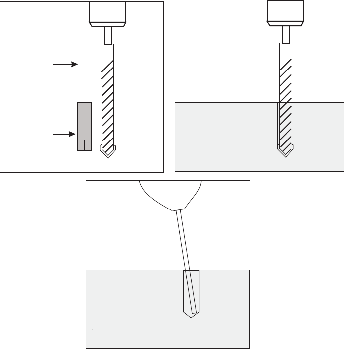
2Drill the anchor holes to the proper size and depth as specified in “Anchor
specifications” (p. 4-7). Refer to the figure below for the anchor hole drilling method.
600.00
422.00
300.00
510.00
449.00
75.50
507.50
57.50
31.00 Typ. 5.00
89.00
600.00
35.00
Front
FRONT EDGE OF LINEUP
Primary Cabinet
Mounting Plate
Radio
Transport, mount, and ground cabinet
How to drill anchor holes and install the mounting plate
for BTS 8420/AWS 8420 radio cabinet
....................................................................................................................................................................................................................................
401-703-444
Issue 4, November 2007 Alcatel-Lucent - Proprietary
See notice on first page 4-9
END OF STEPS
...................................................................................................................................................................................................
...................................................................................................................................................................................................
3Vacuum the holes. You may need to reach into the hole with a tool to remove excess
dust.
Place and level the mounting plate and torque the rear anchors
Use the following procedure to place and level the mounting plate, as well as torque
the rear anchors.
...................................................................................................................................................................................................
1If installing Zone 0, 1, or 2 anchors (1/2- inch diameter drop-in), set the anchors
according to the procedure in the EZBFi Modular Battery Installation Manual for
+24V and -48V, 401-703-507.
12
3
DEPTH
GAUGE
ANCHOR
Transport, mount, and ground cabinet
How to drill anchor holes and install the mounting plate
for BTS 8420/AWS 8420 radio cabinet
....................................................................................................................................................................................................................................
4-10 Alcatel-Lucent - Proprietary
See notice on first page 401-703-444
Issue 4, November 2007
END OF STEPS
...................................................................................................................................................................................................
...................................................................................................................................................................................................
2Place the mounting plate in position over the holes.
...................................................................................................................................................................................................
3Position the retaining bar across the middle of the rear of the plate with the protrusions
on the ends facing down. Then center the retaining bar over the holes in the plate and
over the anchor holes.
Important! Skip the next two steps if installing 12 mm anchor assemblies.
...................................................................................................................................................................................................
4Loosely insert (with washers) the longer (1-1/2 inch) of the rear anchor bolts through
the retaining bar to hold the mounting plate in position while it is being leveled. Do
not tighten the bolts.
Important! Skip the next two steps if installing 1/2 inch diameter drop-in anchors.
...................................................................................................................................................................................................
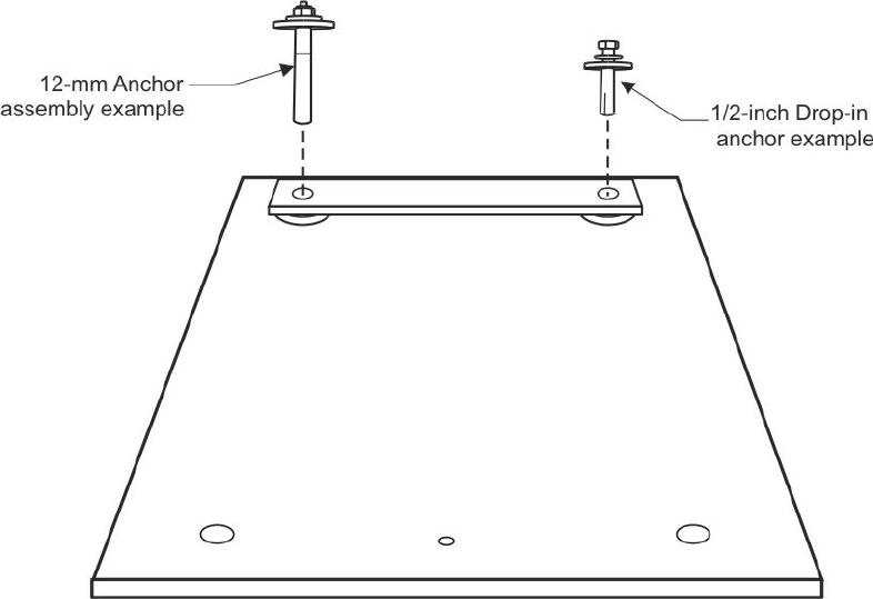
5If installing Zone 3 and 4 anchors (12 mm anchor assemblies), tighten the nut and
firmly place the rear anchor bolt assemblies into the anchor holes through the retaining
bar and the mounting plate. Do not tighten them. Refer to the figure below.
Important! When performing the next step, use a 1/4 inch socket to protect the
head of the threaded rod if it is necessary to tap the anchor assembly into place.
Note that the black shouldered spacer and red cap, included in each 12 mm anchor
kit, are not used.
...................................................................................................................................................................................................
6Tap the anchor assembly into the hole until the large washer is flush with the retaining
bar.
Transport, mount, and ground cabinet
How to drill anchor holes and install the mounting plate
for BTS 8420/AWS 8420 radio cabinet
....................................................................................................................................................................................................................................
401-703-444
Issue 4, November 2007 Alcatel-Lucent - Proprietary
See notice on first page 4-11
Important! When performing the next step, note that each shim has a slot that is
designed to fit around the body of the anchor bolt. Keep the slot properly aligned
when performing this step so that the anchor bolts can later be set.
...................................................................................................................................................................................................
7Insert combinations of shims under the corners of the plate to perform the leveling
process.
Important! When performing the next step, note that the mounting plate must
support the cabinet in a perfectly vertical position, so that the sides will line up
correctly between a radio cabinet and a 3GP24i power cabinet.
...................................................................................................................................................................................................
8Check the level from front to rear, and side to side. Refer to figure below. Correct as
required.
Transport, mount, and ground cabinet
How to drill anchor holes and install the mounting plate
for BTS 8420/AWS 8420 radio cabinet
....................................................................................................................................................................................................................................
4-12 Alcatel-Lucent - Proprietary
See notice on first page 401-703-444
Issue 4, November 2007
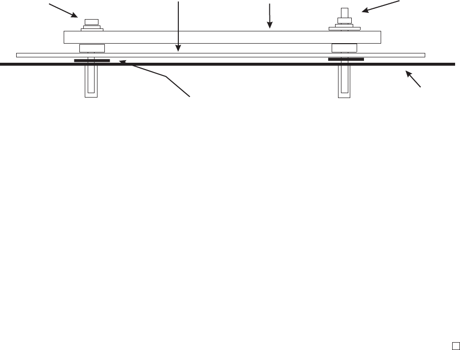
...................................................................................................................................................................................................
9Torque the anchor bolts as follows:
•1/2 inch diameter drop-in anchor bolts: 24 Nm (18 ft-lb)
•12 mm anchor assemblies: 79 Nm (58 ft-lb).
...................................................................................................................................................................................................
10 Once all required mounting plates are in place and leveled and anchored, proceed to “”
(p. 4-14) to continue the installation.
END OF STEPS
...................................................................................................................................................................................................
REAR VIEW SHOWN: LEVEL ALL FOUR CORNERS
1/2-INCH DIA.
DROP-IN
EXAMPLE
12-mm
ASSEMBLY
EXAMPLE
RETAINING
BAR
SURFACE
MOUNTING
PLATE
INSERT SHIMS AS
REQUIRED
Transport, mount, and ground cabinet
How to drill anchor holes and install the mounting plate
for BTS 8420/AWS 8420 radio cabinet
....................................................................................................................................................................................................................................
401-703-444
Issue 4, November 2007 Alcatel-Lucent - Proprietary
See notice on first page 4-13

Lifting and moving cabinets
...................................................................................................................................................................................................................................
Purpose
Radio cabinets are usually shipped to the customer via truck and delivered to the
installation site. During installation, it may be necessary to lift the radio cabinet and
move it to a new location. This section describes how to safely lift a radio cabinet.
Perform the procedures in this chapter to lift and move the radio cabinet.
Lifting machinery
To lift the cabinet, do one of the following:
•Use a forklift with forks that are at least 4 feet long to lift a cabinet that is attached
to a pallet, from the bottom.
•Install lifting eyebolts on the top of the cabinet, and use a derrick and slings to lift
the cabinet from its top.
Safety precautions for using lifting machinery
WARNING
Personnel injury or equipment damage
Cabinets are too heavy to move without appropriate lifting devices.
Derrick equipment or a forklift must be used to lift the cabinet. Do not attempt to move
the cabinet manually, or remove it from the pallet manually.
Comply with the following guidelines when using lifting machinery:
•Only operators who are specifically trained and meet company requirements should
be permitted to operate derrick or forklift equipment.
•All persons working with derricks or forklifts must wear standard safety headgear,
footwear, eye protection, and insulated gloves (if required).
•Do not operate a derrick until both stabilizers are extended and firmly supported.
Do not extend stabilizers after a load is suspended from the derrick.
•While raising the derrick from the stowed position, be alert for overhead
obstructions, such as power lines, that may interfere.
•At all times, keep bystanders away from the work area.
•Operators must not suspend loads over people, nor can any person be permitted to
work, stand, or pass under a suspended load.
•When a cabinet is being lifted with slings, it is unsafe to lift the cabinet when
lifting sling angle is less than 45 degrees to the top of the cabinet.
Transport, mount, and ground cabinet
...................................................................................................................................................................................................................................
4-14 Alcatel-Lucent - Proprietary
See notice on first page 401-703-444
Issue 4, November 2007
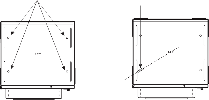
Guidelines for using a derrick
When a derrick is used to move a cabinet, lifting eyebolts and slings are used to attach
the cabinet to the derrick.
Lifting eyebolts
Four R-ITE-6110 M12 lifting eyebolts are screwed into the eyebolt holes on the top of
the cabinet, as shown in the following figure.
Position each lifting eyebolt so that the plane of the eyebolt points at the center of the
top of the cabinet, as shown in the previous figure. When this is done, and the load is
applied, the plane of the eyebolt will align with the load. Eyebolts that are not aligned
with the load can bend as the load pulls on them sideways.
Observe the following guidelines about lifting eyebolts:
•The eyebolts screw into factory-installed nuts on top of the cabinet. These nuts
must be held in position while the lifting eyebolt is screwed in. If this is not done,
the nut can become loose and allow water to leak into the cabinet.
•Do not overtighten the lifting eyebolt.
•The shoulder of the lifting eyebolt must be properly seated (should bear firmly
against the mating part). If it is not, the working loads must be reduced
substantially. A steel washer or spacer may be required for proper seating.
•Tightness and seating must be checked after initial load.
•Lifting eyebolts should never be painted or otherwise coated, because such coatings
will cover up flaws.
TOP VIEW
Holes for
Lifting Eyebolts
TOP VIEW
Lifting Eyebolt
Plane of
Eyebolt
Transport, mount, and ground cabinet
Lifting and moving cabinets
....................................................................................................................................................................................................................................
401-703-444
Issue 4, November 2007 Alcatel-Lucent - Proprietary
See notice on first page 4-15
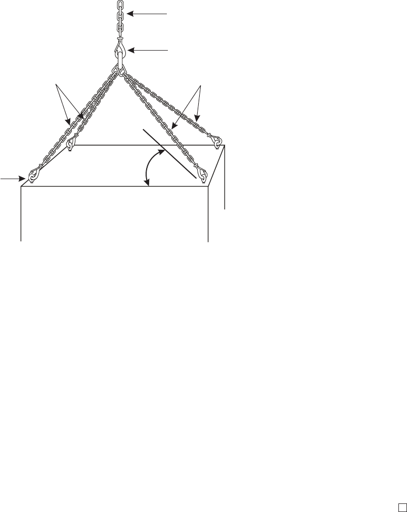
Slings
Attach the slings to the boom line with a B connecting link or clevis. Attach the other
ends of the slings to the lifting eyebolts with a B connecting link or clevis.
When a cabinet is being lifted with slings, it is unsafe to lift the cabinet when the
lifting sling angle is less than 45 degrees to the top of the cabinet. At closer than 45
degrees, there is too much side stress on the lifting eyebolts. Use slings that are long
enough to keep the lifting sling angle at greater than 45 degrees from the top of the
cabinet.
Control the cabinet while it is being lifted
CAUTION
When Moving Cabinet
When moving a cabinet in the following procedures, do not tilt the cabinet beyond 30
degrees from vertical. Do not stand under the cabinet.
A rope tied to the pallet attached to the cabinet should be used to guide the cabinet
while it is being lifted. The rope must be sufficiently long. As the cabinet is being
lifted and transported, use the rope to guide the cabinet and prevent the cabinet from
tilting or swinging.
Always lift cabinets carefully, and keep the boom line tight to prevent the cabinet from
tipping while it is moving. At the end of the lift, slowly place the cabinet on the
ground.
Unsafe if lifting sling angle is
less than 45 degrees
to the top of the cabinet.
Lifting sling
angle
Boom line
B connecting link or clevis
Slings
Lifting
Eyebolt
Slings
Transport, mount, and ground cabinet
Lifting and moving cabinets
....................................................................................................................................................................................................................................
4-16 Alcatel-Lucent - Proprietary
See notice on first page 401-703-444
Issue 4, November 2007

How to place, anchor, and ground cabinets, frames,
or stands
Overview
...................................................................................................................................................................................................................................
Purpose
This section provides the following instructions.
•Placement, anchoring and grounding the indoor Base Station 8420 radio cabinet.
•Placement, anchoring and grounding the EZBFi battery base module, both first and
second.
Contents
Anchor and torque requirements 4-18
Placement, anchoring, and grounding of the indoor radio cabinet 4-19
Transport, mount, and ground cabinet
...................................................................................................................................................................................................................................
401-703-444
Issue 4, November 2007 Alcatel-Lucent - Proprietary
See notice on first page 4-17

Anchor and torque requirements
...................................................................................................................................................................................................................................
Anchor and torque requirements for radio cabinet
The following table provides anchor type and anchor bolt torque requirements for the
radio cabinet.
Seismic
Zone(s) Anchor Type Wrench Torque
Newton
Meters Foot Pounds
0, 1, 2 (4) 1/2 inch diameter
drop in
3/4 inch 24 Nm 18 ft-lb
3, 4* (4) 12 mm
expansion studs
19 mm 79 Nm 58 ft-lb
Transport, mount, and ground cabinet
...................................................................................................................................................................................................................................
4-18 Alcatel-Lucent - Proprietary
See notice on first page 401-703-444
Issue 4, November 2007

Placement, anchoring, and grounding of the indoor radio
cabinet
...................................................................................................................................................................................................................................
Overview
This procedure module provides instructions for placement, anchoring, and grounding
of the radio cabinet.
Move/lift the cabinet into position on the mounting plate
Use the following procedure to move/lift the cabinet into position.
...................................................................................................................................................................................................
1WARNING
Personnel injury or equipment damage
Cabinets are too heavy to move without appropriate lifting devices. When moving the
cabinet, always use appropriate lifting devices and a sufficient number of personnel.
Important! When handling a radio cabinet, care must be taken not to grasp the
removable filter cover, located at the top of the front door of the radio cabinet.
Remove tape and any debris covering the front anchor holes
...................................................................................................................................................................................................
2Place the cabinet on the front of the mounting plate.
...................................................................................................................................................................................................
3Slide the cabinet to the rear of the plate. Make sure that the tongue at the rear of the
cabinet goes under the retaining bar. Refer to the figure below.
Transport, mount, and ground cabinet
...................................................................................................................................................................................................................................
401-703-444
Issue 4, November 2007 Alcatel-Lucent - Proprietary
See notice on first page 4-19
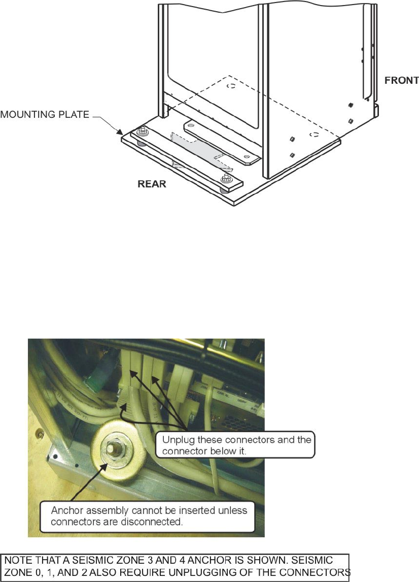
...................................................................................................................................................................................................
4Open the front door of the cabinet to view the front mounting holes.
...................................................................................................................................................................................................
5Mark for identification, and unplug the three lower left connectors shown in the figure
below.
Transport, mount, and ground cabinet
Placement, anchoring, and grounding of the indoor radio
cabinet
....................................................................................................................................................................................................................................
4-20 Alcatel-Lucent - Proprietary
See notice on first page 401-703-444
Issue 4, November 2007
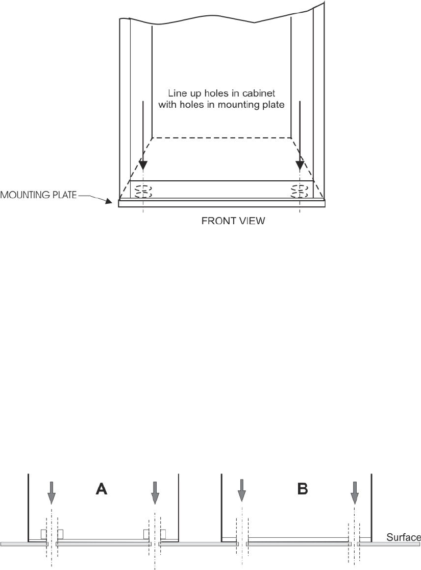
...................................................................................................................................................................................................
6Align the cabinet mounting holes with the set anchors or anchor holes, as applicable.
Refer to the figure below.
Install front anchoring bolts or anchor assemblies
Use the following procedure to install the front anchoring bolts or anchor assemblies.
...................................................................................................................................................................................................
1Install the front anchor bolts as follows.
•Seismic Zones 0, 1, and 2:
1. If the anchors have not been set, tap in the anchors and set them using the
setting tool.
2. If the anchors have already been set, insert the shorter of the anchor bolts
provided (1 inch) with two washers each.
3. Torque the bolts to 18 ft lb (24 Nm).
Transport, mount, and ground cabinet
Placement, anchoring, and grounding of the indoor radio
cabinet
....................................................................................................................................................................................................................................
401-703-444
Issue 4, November 2007 Alcatel-Lucent - Proprietary
See notice on first page 4-21
END OF STEPS
...................................................................................................................................................................................................
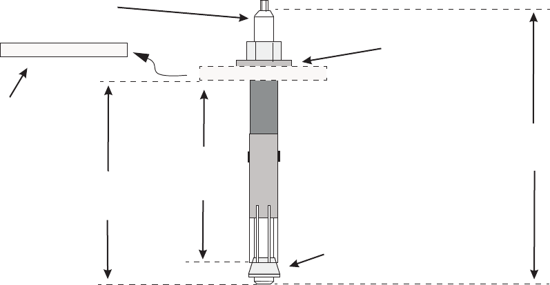
•Seismic Zones 3 and 4:
Note that the black shouldered spacer and red cap, included in each Zone 3 and
4 anchor kit, are not used.
1. Tighten the nut and then insert the entire anchor assembly (12 mm
expansion stud assembly) into each hole.
Note that if the assembly cannot be inserted with the large (plate) washer,
temporarily remove the washer and replace and retighten the nut.
When tapping the anchor assembly into place when performing the next
step, use a 1/4 inch socket to protect the head of the threaded rod.
2. Tap the anchors into the front mounting holes until the washer is flush with
the bottom of the cabinet.
3. Skip the next step if the plate washer has not been removed.
4. Remove the nut and flat washer, then replace the plate washer, flat washer,
and nut in the order shown below. Retighten the nut.
5. Torque the nut to 58 ft lb. (79 Nm) using a ratchet and 19 mm deep socket.
Important! The connectors unplugged in Step 5 must be reconnected at this time.
...................................................................................................................................................................................................
2Reconnect the connectors unplugged in Step 5.
NUT
PLATE WASHER
(TEMPORAIRLY
REMOVED IF
NECESSARY)
SPREADER
NUT
FLAT
WASHER
THREADED
ROD
125 mm
(5 inches)
87 mm
(3.5 inches)
100 mm
(4 inches)
Transport, mount, and ground cabinet
Placement, anchoring, and grounding of the indoor radio
cabinet
....................................................................................................................................................................................................................................
4-22 Alcatel-Lucent - Proprietary
See notice on first page 401-703-444
Issue 4, November 2007
END OF STEPS
...................................................................................................................................................................................................
Attach grounding cables to the BTS 8420/AWS 8420 radio cabinet without integrated power
Important! If installing a BTS 8420/AWS 8420 radio cabinet, skip this procedure
and go to next procedure, Attach grounding cables to the BTS 8420/AWS 8420
radio cabinet with integrated power.
Perform the following steps to attach the grounding cables.
...................................................................................................................................................................................................
1Verify that power is not connected to the power cabinet.
Important! When performing the next step, if a supplementary ground is not
present, and one is not going to be installed at the present time, the two cabinet
ground cables must have sufficient length to reach the main bus bar.
...................................................................................................................................................................................................
2Prepare two 6 AWG grounding cables of sufficient length to reach from the
supplementary ground wire, at the cable rack, to the top of the BTS 8420/AWS 8420
radio cabinet.
...................................................................................................................................................................................................
3Strip approximately 13 mm (1/2 inch) of insulation from both ends of each grounding
cable.
Important! When performing the next step, if a supplementary ground is not
present, the two cabinet ground cables must be directly attached to the main bus
bar. Do not attach the cabinet grounding cables to the halo ground under any
circumstances.
...................................................................................................................................................................................................
4Connect each of the grounding cables to the supplementary ground, using a c-tap or
terminal lug.
...................................................................................................................................................................................................
5Remove the four lifting eye bolts.
...................................................................................................................................................................................................
6Remove the double-hole grounding lug from the top of the BTS 8420/AWS 8420 radio
cabinet. Refer to the figure below.
Transport, mount, and ground cabinet
Placement, anchoring, and grounding of the indoor radio
cabinet
....................................................................................................................................................................................................................................
401-703-444
Issue 4, November 2007 Alcatel-Lucent - Proprietary
See notice on first page 4-23
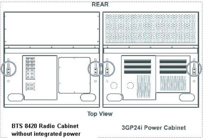
...................................................................................................................................................................................................
7Verify that the cabinet grounding lug location is free of paint and polish, if required.
...................................................................................................................................................................................................
8Insert the grounding cable into the grounding lug and crimp the lug in two places to
secure the grounding cable. Repeat for the other cable.
Important! When performing the next step, the lock washer must be installed
between the M6 flat washer and the nut
...................................................................................................................................................................................................
9Use antioxidant compound and reinstall the lug on the cabinet using the supplied M6
washers, lock washers, and nuts. Repeat for the other cable. Refer to the figure below.
Transport, mount, and ground cabinet
Placement, anchoring, and grounding of the indoor radio
cabinet
....................................................................................................................................................................................................................................
4-24 Alcatel-Lucent - Proprietary
See notice on first page 401-703-444
Issue 4, November 2007
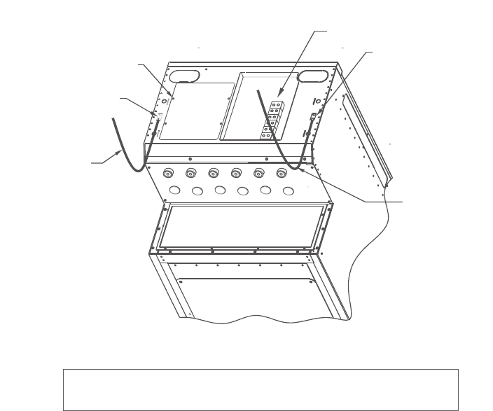
...................................................................................................................................................................................................
10 Torque the cabinet grounding connections to 6 Nm (54 in-lb).
...................................................................................................................................................................................................
11 Repeat steps 1 through 10 for the 3GP24i power cabinet, if applicable.
Attach grounding cables to the BTS 8420/AWS 8420 radio cabinet with integrated power
Important! Verify that the power is not connected to the cabinet.
Perform the following steps to attach the grounding cables.
...................................................................................................................................................................................................
1Prepare two 6 AWG grounding cables of sufficient length to reach from the
supplementary ground wire, at the cable rack, to the top of the radio cabinet.
GROUND LUG
DC TERMINAL BLOCKS
GROUND LUG
HATCHPLATE
GROUND WIRE
GROUND WIRE
FRONT
REAR
GROUNDING OF THE 3GP24i POWER CABINET (NOT SHOWN)
IS IDENTICAL TO THE GROUNDING OF THE PRIMARY CABINET
Transport, mount, and ground cabinet
Placement, anchoring, and grounding of the indoor radio
cabinet
....................................................................................................................................................................................................................................
401-703-444
Issue 4, November 2007 Alcatel-Lucent - Proprietary
See notice on first page 4-25
END OF STEPS
...................................................................................................................................................................................................
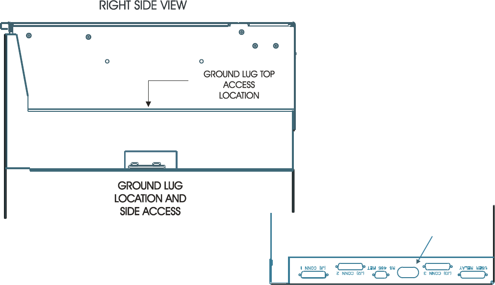
...................................................................................................................................................................................................
2Strip approximately 12 mm (1/2 inch) of insulation from both ends of each grounding
cable. Connect the grounding cables to the supplementary ground, or other grounding
system, using a C-tap or terminal lug.
...................................................................................................................................................................................................
3Remove the double-hole grounding lug from the top right of the radio cabinet. Refer to
the figure below.
...................................................................................................................................................................................................
4Verify that the cabinet grounding lug location is free of paint and polish, if required.
...................................................................................................................................................................................................
5Insert a grounding cable into a grounding lug and crimp the lug in two places to secure
the grounding cable.
...................................................................................................................................................................................................
6Insert the grounding cable through the rear opening in the left integrated power module
frame. Refer to the figure below.
ACCESS TO
EXTERNAL
GROUND
LUG
TOP VIEW
Transport, mount, and ground cabinet
Placement, anchoring, and grounding of the indoor radio
cabinet
....................................................................................................................................................................................................................................
4-26 Alcatel-Lucent - Proprietary
See notice on first page 401-703-444
Issue 4, November 2007
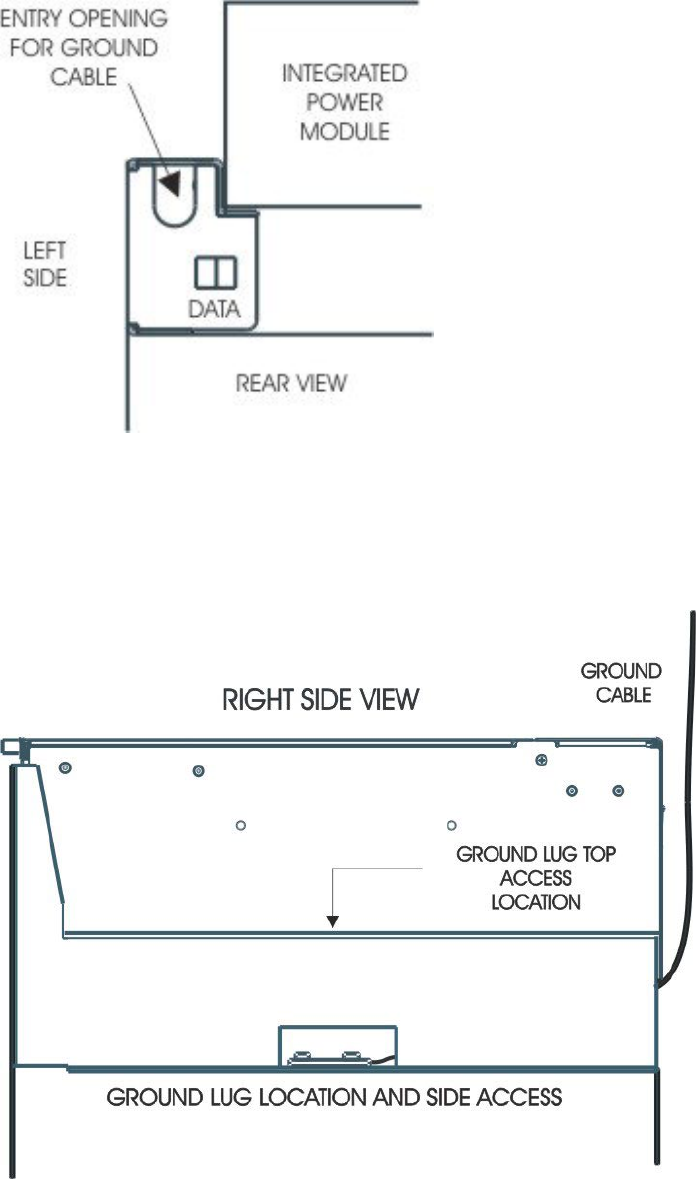
...................................................................................................................................................................................................
7Reinstall the lug on the cabinet using the supplied M6 washers, lock washers, and nuts.
Refer to the figure below.
Transport, mount, and ground cabinet
Placement, anchoring, and grounding of the indoor radio
cabinet
....................................................................................................................................................................................................................................
401-703-444
Issue 4, November 2007 Alcatel-Lucent - Proprietary
See notice on first page 4-27
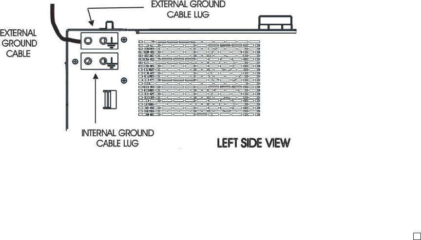
...................................................................................................................................................................................................
8Torque the cabinet grounding connection to 6 Nm (54 in-lb).
...................................................................................................................................................................................................
9Remove the double-hole grounding lug from the left rear of the integrated power
module. There are two lugs. Remove the one not in use. Refer to the figure below.
...................................................................................................................................................................................................
10 Verify that the cabinet grounding lug location is free of paint and polish, if required.
...................................................................................................................................................................................................
11 Insert the remaining grounding cable into a grounding lug and crimp the lug in two
places to secure the grounding cable.
...................................................................................................................................................................................................
12 Reinstall the lug on the cabinet using the supplied M6 washers, lock washers, and nuts.
Refer to the figure below.
...................................................................................................................................................................................................
13 Torque the cabinet grounding connection to 6 Nm (54 in-lb).
END OF STEPS
...................................................................................................................................................................................................
Transport, mount, and ground cabinet
Placement, anchoring, and grounding of the indoor radio
cabinet
....................................................................................................................................................................................................................................
4-28 Alcatel-Lucent - Proprietary
See notice on first page 401-703-444
Issue 4, November 2007

55Connecting cables to BTS
8420/AWS 8420 radio cabinet
Overview
...................................................................................................................................................................................................................................
Purpose
This chapter provides instructions for connecting the GPS antenna jumper cable, T1/E1
cables, external User Alarm cable, and Power Alarm cable to the Base Station
8420/AWS 8420 radio cabinet.
Contents
How to connect the GPS antenna jumper cable 5-2
Connecting GPS antenna jumper cable 5-3
How to connect T1/E1 lines and external alarm cables 5-10
How to route and connect T1/E1 cables to BTS 8420/AWS 8420 radio
cabinet
5-16
How to route and connect User Alarm cable(s) to indoor BTS 8420/AWS
8420 radio cabinet
5-40
Balun block connections (if applicable) 5-61
How to connect twisted-wire pairs in T1/E1 cable(s) to Balun Blocks 5-62
...................................................................................................................................................................................................................................
401-703-444
Issue 4, November 2007 Alcatel-Lucent - Proprietary
See notice on first page 5-1

How to connect the GPS antenna jumper cable
Overview
...................................................................................................................................................................................................................................
Purpose
This procedure module provides instructions for connecting the GPS antenna jumper
cable in an indoor installation.
Description of GPS antenna cable
The indoor BTS 8420/AWS 8420 radio cabinet is supplied with a connector for one
GPS antenna jumper cable. The GPS antenna jumper cable is terminated at one end
with an N-type male connector. The end with the N-type male connector is connected
to the Universal Hatchplate on the BTS 8420/AWS 8420 radio cabinet without
integrated power and to the IPM on the BTS 8420/AWS 8420 radio cabinet with
integrated power. A DIN connector is installed at the other end of the GPS antenna
jumper cable. This end is connected to the surge protector at the room hatchplate or
customer’s DAS.
Important! Refer to Alcatel-Lucent CDMA Base Station BTS 8420/AWS 8420
Indoor Site Preparation Guidelines, 401-703-443, to verify correct installation of
the GPS antenna.
Contents
Connecting GPS antenna jumper cable 5-3
Connecting cables to BTS 8420/AWS 8420 radio cabinet
...................................................................................................................................................................................................................................
5-2 Alcatel-Lucent - Proprietary
See notice on first page 401-703-444
Issue 4, November 2007
Connecting GPS antenna jumper cable
...................................................................................................................................................................................................................................
Important! The GPS antenna jumper cable must be connected before initial
start-up and testing can take place. DO NOT connect RF (Tx and Rx) jumper
cables at this time.
Connecting GPS antenna jumper cable to BTS 8420/AWS 8420 radio cabinet with integrated
power
Use the following procedure to connect the GPS antenna jumper cable to the BTS
8420/AWS 8420 radio cabinet with integrated power. (The GPS antenna jumper cable
is connected to the Integrated Power Module (IPM) on the radio cabinet.)
...................................................................................................................................................................................................
1Label both ends of the GPS antenna jumper cable with “GPS.” The end of the GPS
antenna jumper cable, with the N-type connector, is connected to the radio cabinet.
Route the other end of the GPS antenna jumper cable over the ladder rack and to the
customer’s DAS. Refer to the figure below. This figure applies to both the BTS 8420
and AWS 8420 radio cabinet.
Connecting cables to BTS 8420/AWS 8420 radio cabinet
...................................................................................................................................................................................................................................
401-703-444
Issue 4, November 2007 Alcatel-Lucent - Proprietary
See notice on first page 5-3
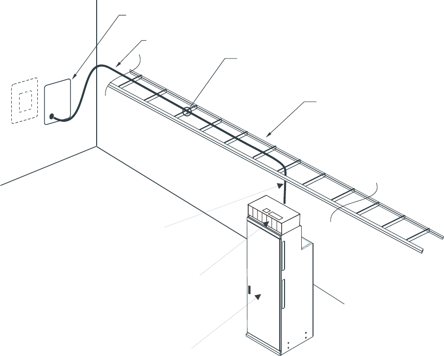
...................................................................................................................................................................................................
2Connect the N-type connector to the “GPS IN” connector at the top-rear of the
Integrated Power Module. See the figure below.
HORIZONTAL
LADDER RACK
GPS ANTENNA JUMPER CABLE
ROOM HATCHPLATE
TIE CABLE TO
LADDER RACK
TO BRACKET ON
INTEGRATED POWER
MODULE
INTEGRATED POWER
MODULE
BTS 8420 RADIO CABINET
Connecting cables to BTS 8420/AWS 8420 radio cabinet
Connecting GPS antenna jumper cable
....................................................................................................................................................................................................................................
5-4 Alcatel-Lucent - Proprietary
See notice on first page 401-703-444
Issue 4, November 2007
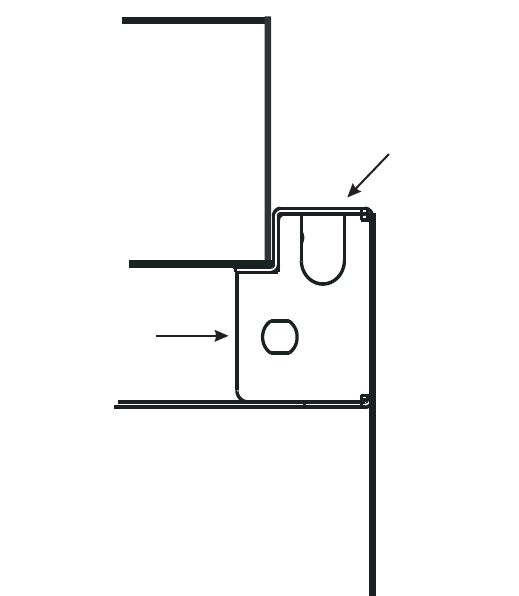
...................................................................................................................................................................................................
3Torque the GPS antenna jumper cable N-type connector to 1.7 Nm (15 in-lb) .
Connecting GPS antenna jumper cable to BTS 8420/AWS 8420 radio cabinet without integrated
power
Use the following procedure to connect the GPS antenna jumper cable to the BTS
8420/AWS 8420 radio cabinet without integrated power. (The GPS antenna jumper
cable is connected to the Universal Hatchplate on the BTS 8420/AWS 8420 radio
cabinet.)
...................................................................................................................................................................................................
1Label both ends of the GPS antenna jumper cable with “GPS.” The end of the GPS
antenna jumper cable, terminated with a N-type connector, is connected to the BTS
8420/AWS 8420 radio cabinet. Route the other end of the GPS antenna jumper cable
over the ladder rack and to the room hatchplate. Refer to the figure below. (The figure
below shows a typical room hatchplate and applies to both the BTS 8420 and AWS
8420 radio cabinet.)
INTEGRATED
POWER
MODULE
RIGHT
SIDE
REAR
VIEW
GPS IN
GPS ANTENNA
CONNECTION
RIGHT SIDE BRACKET
Connecting cables to BTS 8420/AWS 8420 radio cabinet
Connecting GPS antenna jumper cable
....................................................................................................................................................................................................................................
401-703-444
Issue 4, November 2007 Alcatel-Lucent - Proprietary
See notice on first page 5-5
END OF STEPS
...................................................................................................................................................................................................
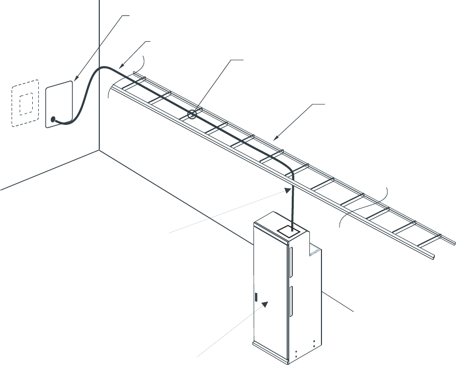
...................................................................................................................................................................................................
2Connect the N-type connector to the “GPS IN” connector on the Universal Hatchplate,
on top of the BTS 8420/AWS 8420 radio cabinet. See the figure below.
HORIZONTAL
LADDER RACK
GPS ANTENNA JUMPER CABLE
ROOM HATCHPLATE
TIE CABLE TO
LADDER RACK
TO UNIVERSAL HATCHPLATE
BTS 8420 RADIO CABINET
Connecting cables to BTS 8420/AWS 8420 radio cabinet
Connecting GPS antenna jumper cable
....................................................................................................................................................................................................................................
5-6 Alcatel-Lucent - Proprietary
See notice on first page 401-703-444
Issue 4, November 2007
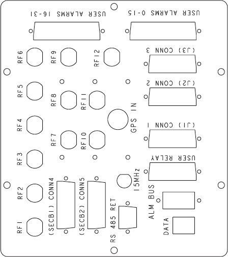
...................................................................................................................................................................................................
3Torque the GPS antenna jumper cable N-type connector to 1.7 Nm (15 in-lb).
Connect GPS antenna jumper cable to GPS surge protector at customer’s DAS
Use the following procedure to connect the GPS antenna jumper cable to the GPS
surge protector at the room hatchplate.
...................................................................................................................................................................................................
1Important! Skip the first two steps of this procedure if the GPS antenna jumper
cable is already terminated at the hatchplate.
Cut the cable to the correct length, allowing plenty of slack.
Important! Be sure to remark the GPS antenna jumper cable if the marking at the
end of the cable is missing.
...................................................................................................................................................................................................
2Strip the end of the GPS antenna jumper cable with the stripping tool (part number
provided in Chapter 3). Terminate the GPS antenna jumper cable with the supplied
7/16 inch DIN connector.
FRONT
Connecting cables to BTS 8420/AWS 8420 radio cabinet
Connecting GPS antenna jumper cable
....................................................................................................................................................................................................................................
401-703-444
Issue 4, November 2007 Alcatel-Lucent - Proprietary
See notice on first page 5-7
END OF STEPS
...................................................................................................................................................................................................
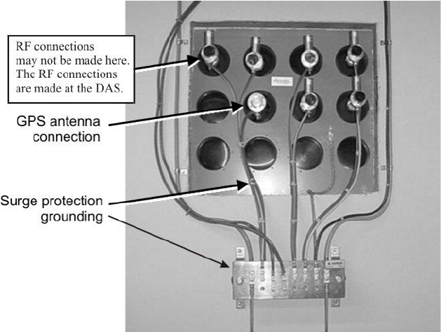
...................................................................................................................................................................................................
3Connect the GPS antenna jumper cable to the GPS cable surge protector at the room
hatchplate (see figure below).
Important! When connecting the GPS antenna jumper cable to the 7/16 DIN
female connector or disconnecting the GPS antenna jumper cable from the 7/16
DIN female connector, it is recommended that the jumper cable be connected or
disconnected as shown in the figure below. Note that the mating connector must be
supported with a wrench. Two wrenches are required to preform this operation. The
7/16 DIN male connector has a captive, rotating coupling nut.
...................................................................................................................................................................................................
4Torque the GPS antenna jumper cable at the room hatchplate to 25 Nm (221 in-lb)
using the method shown in the figure below.
Connecting cables to BTS 8420/AWS 8420 radio cabinet
Connecting GPS antenna jumper cable
....................................................................................................................................................................................................................................
5-8 Alcatel-Lucent - Proprietary
See notice on first page 401-703-444
Issue 4, November 2007
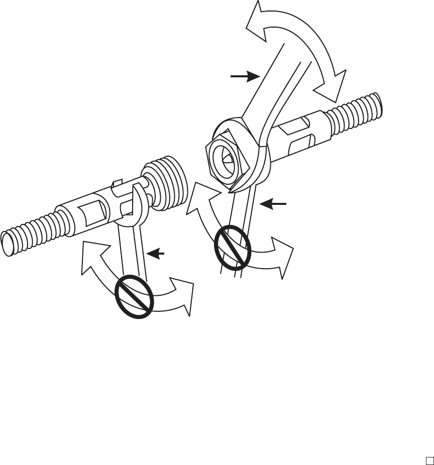
Important! When performing the next step, secure the cable to the ladder rack
using standard procedures, including the use of cable ties.
...................................................................................................................................................................................................
5Tie the GPS antenna cable to the ladder rack. “Connecting GPS antenna jumper cable
to BTS 8420/AWS 8420 radio cabinet with integrated power” (p. 5-3)
END OF STEPS
...................................................................................................................................................................................................
32mm
22mm
221 - 250 lb-IN
25 - 30 N-m
22mm
Connecting cables to BTS 8420/AWS 8420 radio cabinet
Connecting GPS antenna jumper cable
....................................................................................................................................................................................................................................
401-703-444
Issue 4, November 2007 Alcatel-Lucent - Proprietary
See notice on first page 5-9
How to connect T1/E1 lines and external alarm
cables
Overview
...................................................................................................................................................................................................................................
Purpose
The following instructions assume that associated wiring and punchdown blocks have
been provided as part of site preparation, according to the following document:
•Alcatel-Lucent CDMA Base Station BTS 8420/AWS 8420 Indoor Site Preparation
Guidelines, 401-703-443
The following wiring interfaces to the radio cabinet are covered in this section.
•T1/E1
•External alarms.
The following punchdown block is covered in this section.
•Z-IDC.
The BTS 8420 radio cabinet can contain one or two Digital Shelves. Each Digital
Shelf can accept up to 12 T1/E1 lines.
Connecting cables to BTS 8420/AWS 8420 radio cabinet
...................................................................................................................................................................................................................................
5-10 Alcatel-Lucent - Proprietary
See notice on first page 401-703-444
Issue 4, November 2007
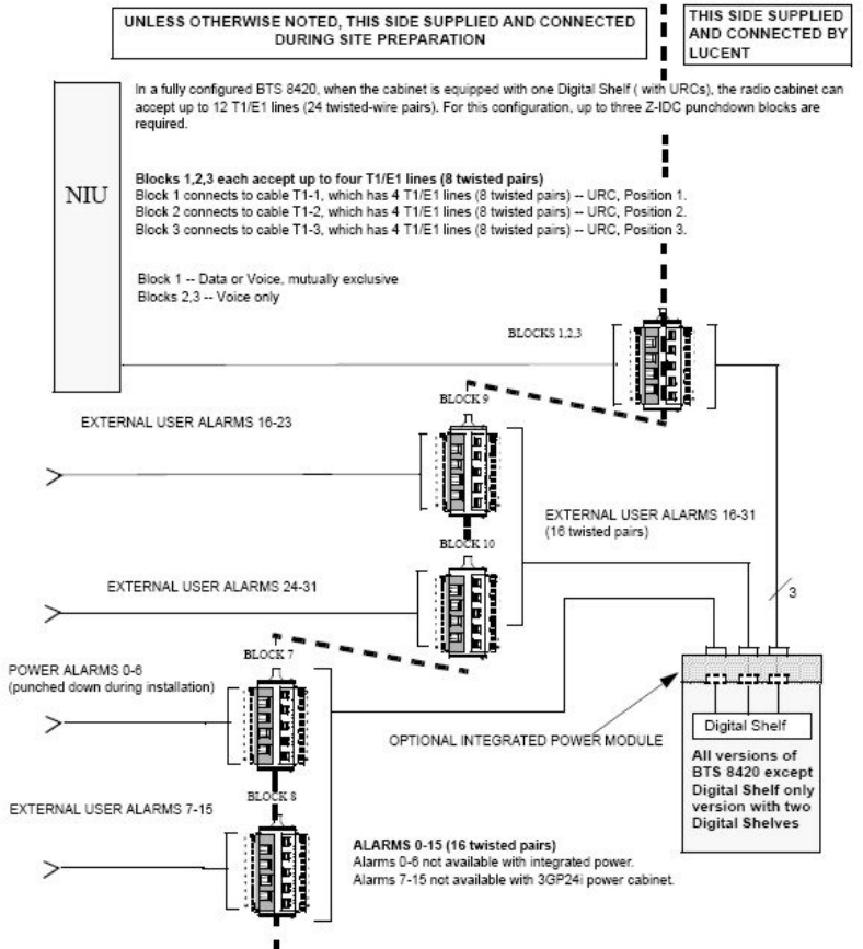
Overview wiring block diagram for T1/E1 lines and external User Alarms to Z-IDC punchdown
blocks for AWS 8420 and all BTS 8420 versions except Digital Only version with two Digital
Shelves
Refer to the figure below for an overview wiring block diagram of the T1/E1 and
external User Alarm wiring to the Z-IDC punchdown blocks for all versions of the
BTS 8420 (except the Digital Only version with two Digital Shelves) and the three
sector and six sector versions of the AWS 8420.
Important! The Z-IDC punchdown block module and mounting bracket are used
only if the network interface unit (NIU) is located more than the 10 meter (33 foot)
cable length from the BTS 8420 radio cabinet. The customer may also use the
Z-IDC to collect alarm cables from various locations.
Connecting cables to BTS 8420/AWS 8420 radio cabinet
Overview
....................................................................................................................................................................................................................................
401-703-444
Issue 4, November 2007 Alcatel-Lucent - Proprietary
See notice on first page 5-11
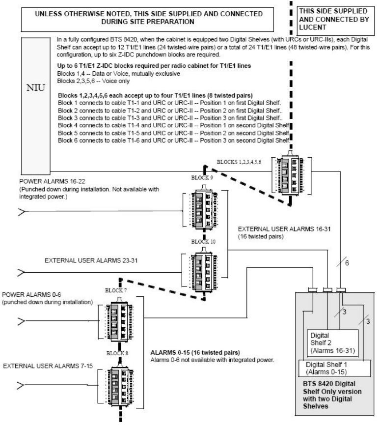
Overview wiring block diagram for T1/E1 lines and external User Alarms to Z-IDC punchdown
blocks for BTS 8420 Digital Only version with two Digital Shelves
Refer to the figure below for an overview wiring block diagram of the T1/E1 and
external User Alarm wiring to the Z-IDC punchdown blocks for the Digital Only
version with two Digital Shelves.
Important! The Z-IDC punchdown block module and mounting bracket are used
only if the network interface unit (NIU) is located more than the 10 meter (33 foot)
cable length from the BTS 8420 radio cabinet. The customer may also use the
Z-IDC to collect alarm cables from various locations.
Connecting cables to BTS 8420/AWS 8420 radio cabinet
Overview
....................................................................................................................................................................................................................................
5-12 Alcatel-Lucent - Proprietary
See notice on first page 401-703-444
Issue 4, November 2007
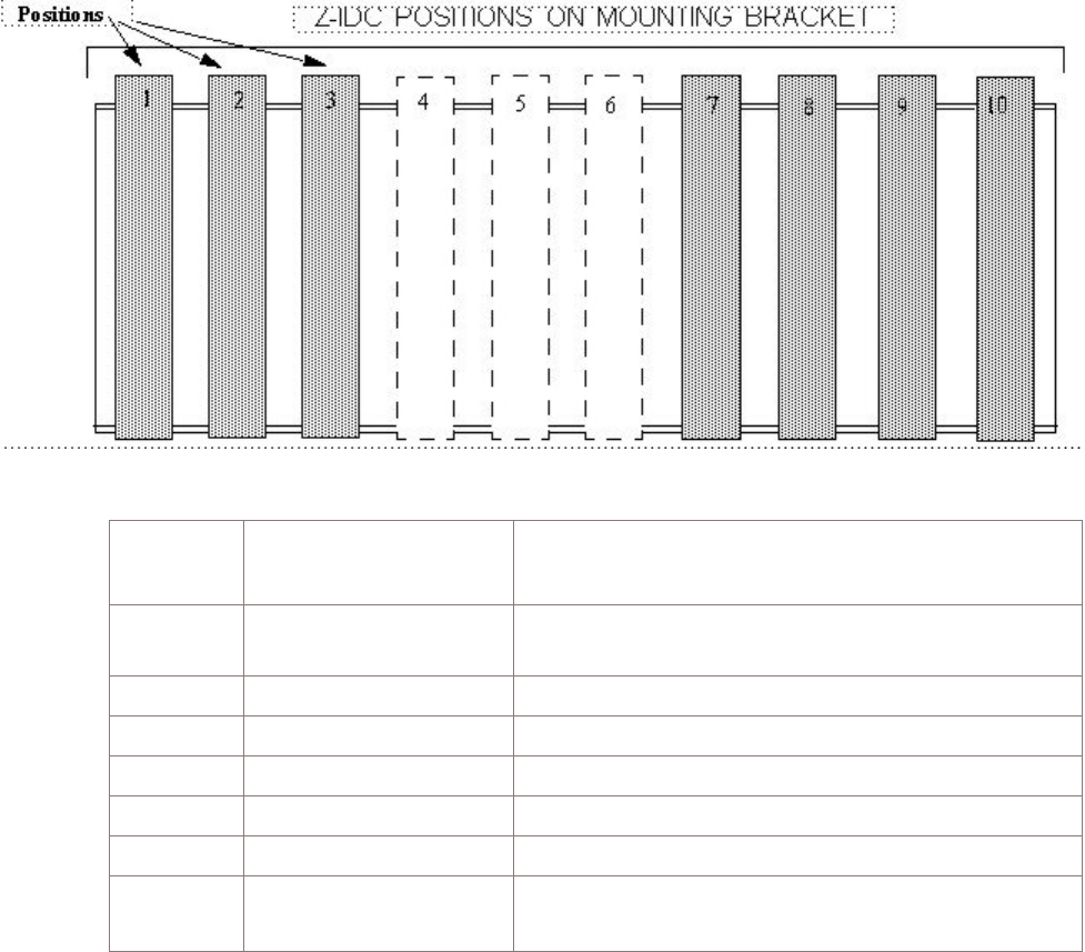
Layout of Z-IDC punchdown blocks
Important! The Z-IDC punchdown block module and mounting bracket are used
only if the network interface unit (NIU) or wall mounting bracket is located more
than the 10 meter (33 foot) cable length from the BTS 8420/AWS 8420 radio
cabinet.
The figure and table below apply to all versions of the BTS 8420 and AWS 8420
except the Digital Only version with two Digital Shelves. The figure below shows the
position numbers of the Z-IDC punchdown blocks on the wall mounting bracket or
NIU. The table below the figure lists the position number of the URC (or URC-II) on
the Digital Shelf and the position number of the Z-IDC block on the wall mounting
bracket or NIU that corresponds to it. Also, shown is the function assigned to each
position number.
Z-IDC block
mounting
position
URC (or URC-II) position
number on Digital Shelf Z-IDC block function
1 URC or URC-II Position 1 DATA (One to four T1/E1 Lines, as available) or
VOICE (One to four T1/E1 Lines). (Mutually exclusive.)
2 URC or URC-II Position 2 VOICE ONLY (One to four T1/E1 Lines)
3 URC or URC-II Position 3 VOICE ONLY (One to four T1/E1 Lines)
4 N/A BLANK (Possible future T1/E1 lines)
5 N/A BLANK (Possible future T1/E1 lines)
6 N/A BLANK (Possible future T1/E1 lines)
7 N/A USER ALARMS 0 to 6 (Non-Alcatel-Lucent Power Alarms
only.)
Connecting cables to BTS 8420/AWS 8420 radio cabinet
Overview
....................................................................................................................................................................................................................................
401-703-444
Issue 4, November 2007 Alcatel-Lucent - Proprietary
See notice on first page 5-13
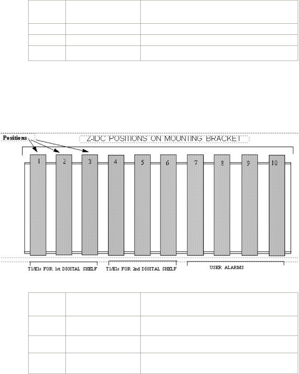
Z-IDC block
mounting
position
URC (or URC-II) position
number on Digital Shelf Z-IDC block function
8 N/A USER ALARMS 7 to 15
9 N/A USER ALARMS 16 to 23
10 N/A USER ALARMS 24 to 31
The figure and table below apply only to the BTS 8420 Digital Only version with two
Digital Shelves. The figure below shows the position numbers of the Z-IDC
punchdown blocks on the wall mounting bracket or NIU. The table below the figure
lists the position number of the URC (or URC-II) on the Digital Shelf and the position
number of the Z-IDC block on the wall mounting bracket or NIU that corresponds to
it. Also, shown is the function assigned to each position number.
Z-IDC block
mounting
position
URC (or URC-II) position
number on Digital Shelf Z-IDC block function
1 URC or URC-II Position 1
on first Digital Shelf DATA (One to four T1/E1 Lines, as available) or
VOICE (One to four T1/E1 Lines). (Mutually exclusive.)
2 URC or URC-II Position 2
on first Digital Shelf VOICE ONLY (One to four T1/E1 Lines)
3 URC or URC-II Position 3
on first Digital Shelf VOICE ONLY (One to four T1/E1 Lines)
Connecting cables to BTS 8420/AWS 8420 radio cabinet
Overview
....................................................................................................................................................................................................................................
5-14 Alcatel-Lucent - Proprietary
See notice on first page 401-703-444
Issue 4, November 2007

Z-IDC block
mounting
position
URC (or URC-II) position
number on Digital Shelf Z-IDC block function
4 URC or URC-II Position 1
on second Digital Shelf DATA (One to four T1/E1 Lines, as available) or
VOICE (One to four T1/E1 Lines). (Mutually exclusive.)
5 URC or URC-II Position 2
on second Digital Shelf VOICE ONLY (One to four T1/E1 Lines)
6 URC or URC-II Position 3
on second Digital Shelf VOICE ONLY (One to four T1/E1 Lines)
7 N/A USER ALARMS 0 to 6 (Non-Alcatel-Lucent Power Alarms
only.)
8 N/A USER ALARMS 7 to 15
9 N/A USER ALARMS 16 to 22 (Non-Alcatel-Lucent Power
Alarms only.)
10 N/A USER ALARMS 23 to 31
Contents
How to route and connect T1/E1 cables to BTS 8420/AWS 8420 radio
cabinet
5-16
How to route and connect User Alarm cable(s) to indoor BTS 8420/AWS
8420 radio cabinet
5-40
Connecting cables to BTS 8420/AWS 8420 radio cabinet
Overview
....................................................................................................................................................................................................................................
401-703-444
Issue 4, November 2007 Alcatel-Lucent - Proprietary
See notice on first page 5-15
How to route and connect T1/E1 cables to BTS 8420/AWS
8420 radio cabinet
...................................................................................................................................................................................................................................
Overview
This procedure module provides instructions for the routing and connecting T1/E1
cables to the indoor radio cabinet. This applies to radio cabinets with and without
integrated power.
Connect T1/E1 cables to BTS 8420/AWS 8420 radio cabinet
Perform the following steps to connect the T1/E1 cables to the BTS 8420/AWS 8420
radio cabinet.
...................................................................................................................................................................................................
1Important! Skip this step if the BTS 8420/AWS 8420 radio cabinet has integrated
power and go to Step 2.
Locate the T1/E1 cables that are shipped with the BTS 8420/AWS 8420 radio cabinet.
For the AWS 8420 and all versions of the BTS 8420 except the Digital Only version
with two Digital Shelves, ensure both ends of the cables are marked “T1-1,” “T1-2,”
and “T1-3” (as applicable) and connect them to the hatchplate on the BTS 8420/AWS
8420 radio cabinet. Refer to the figure below.
Connecting cables to BTS 8420/AWS 8420 radio cabinet
...................................................................................................................................................................................................................................
5-16 Alcatel-Lucent - Proprietary
See notice on first page 401-703-444
Issue 4, November 2007
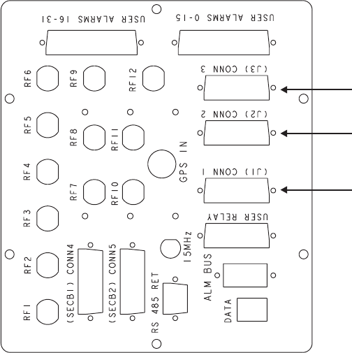
For the Digital Only version with two Digital Shelves, ensure both ends of the cables
are labeled “T1-1 for Digital Shelf 1”, “T1-2 for Digital Shelf 1,” “T1-3 for Digital
Shelf 1,” “T1-4 for Digital Shelf 2,” “T1-5 for Digital Shelf 2,” and “T1-6 for Digital
Shelf 2,” as applicable, and connect them to hatchplate on the BTS 8420 radio cabinet.
The figure below shows the hatchplate with original labels.
FRONT
CONNECT T1-3 (J3)
CABLE HERE
CONNECT T1-2 (J2)
CABLE HERE
CONNECT T1-1 (J1)
CABLE HERE
Connecting cables to BTS 8420/AWS 8420 radio cabinet
How to route and connect T1/E1 cables to BTS
8420/AWS 8420 radio cabinet
....................................................................................................................................................................................................................................
401-703-444
Issue 4, November 2007 Alcatel-Lucent - Proprietary
See notice on first page 5-17