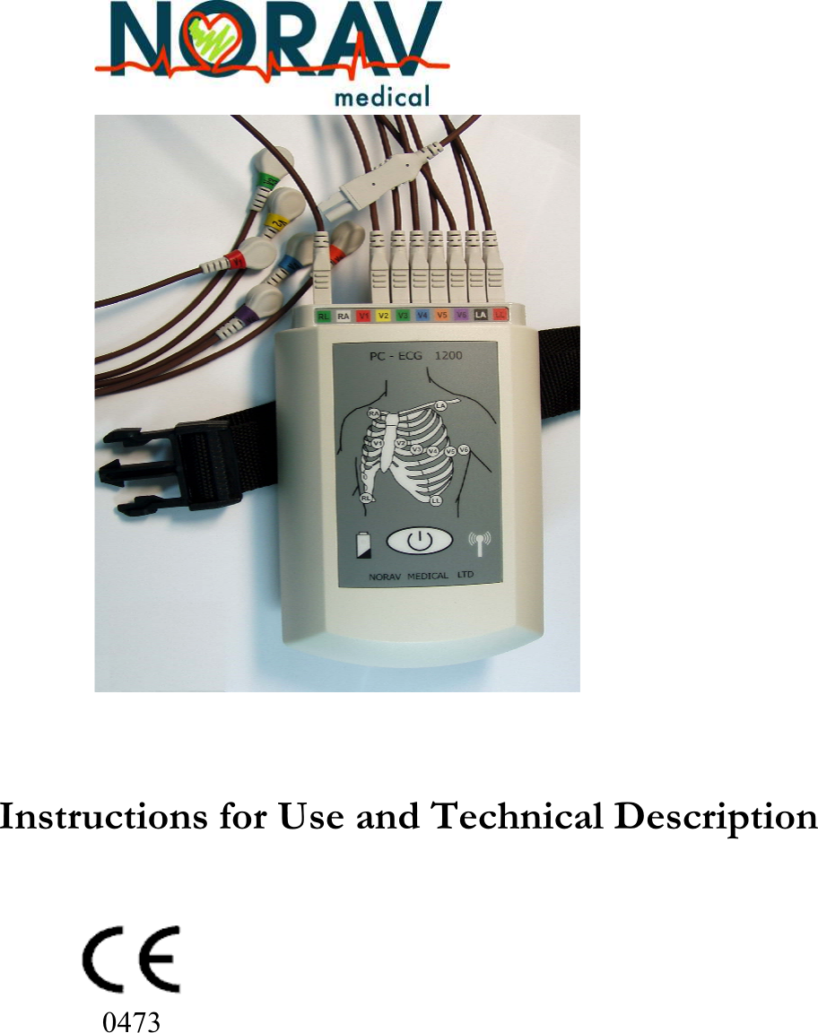
Norav Medical 1200WR WIRELESS ECG RECORDING SYSTEM User Manual PCECG1200WR Revised UserMan
Norav Medical Ltd. WIRELESS ECG RECORDING SYSTEM PCECG1200WR Revised UserMan
UserManual.wiki
>
Norav Medical
>
1200WR User Manual
>
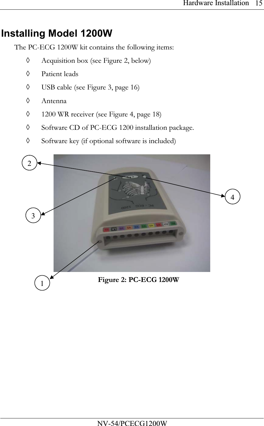
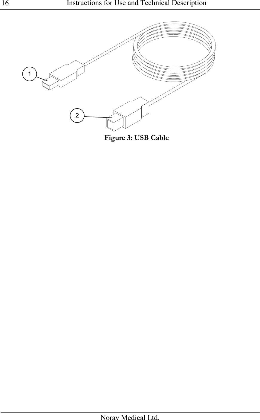
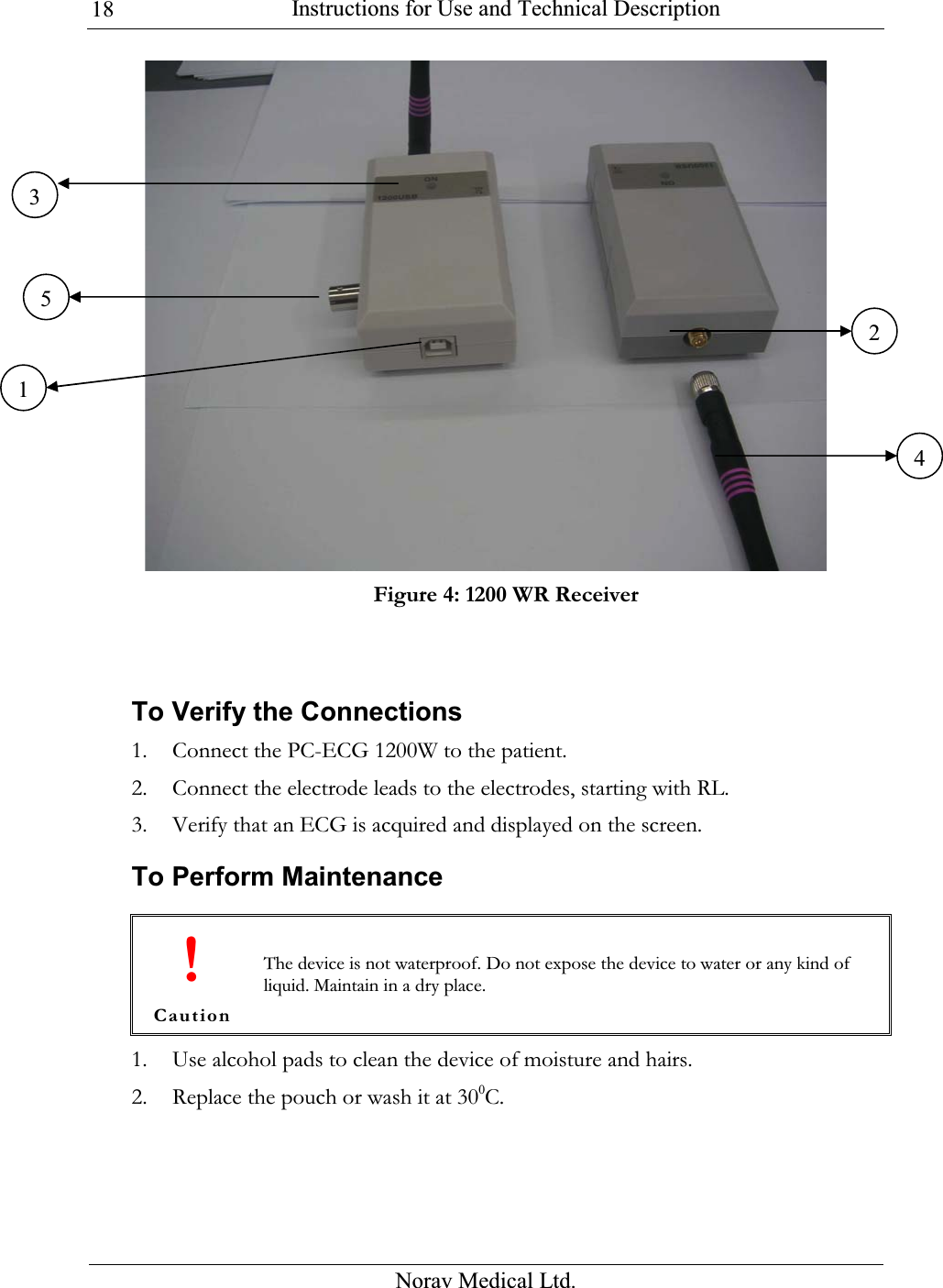
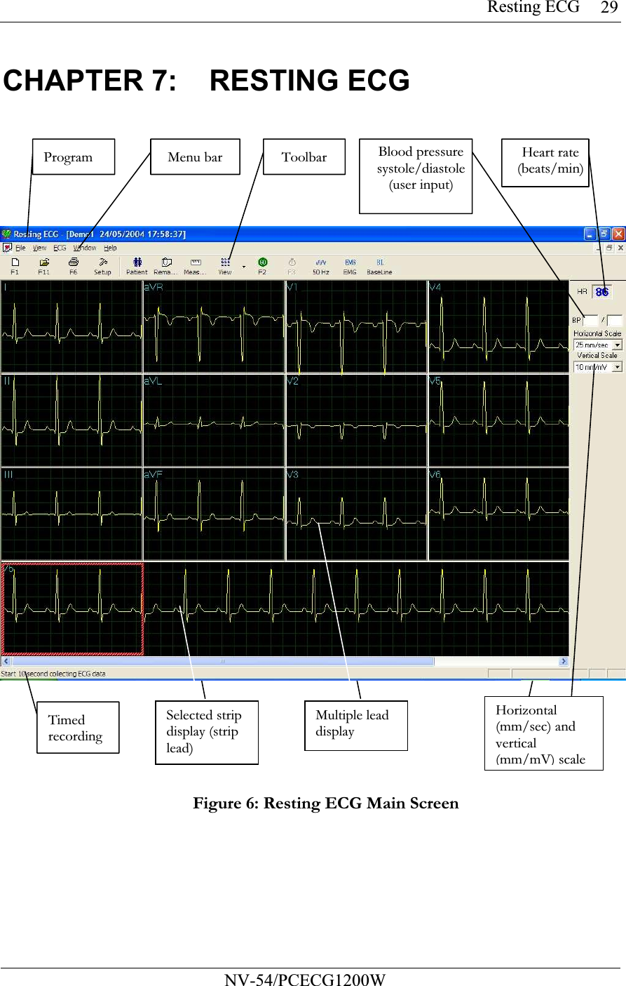
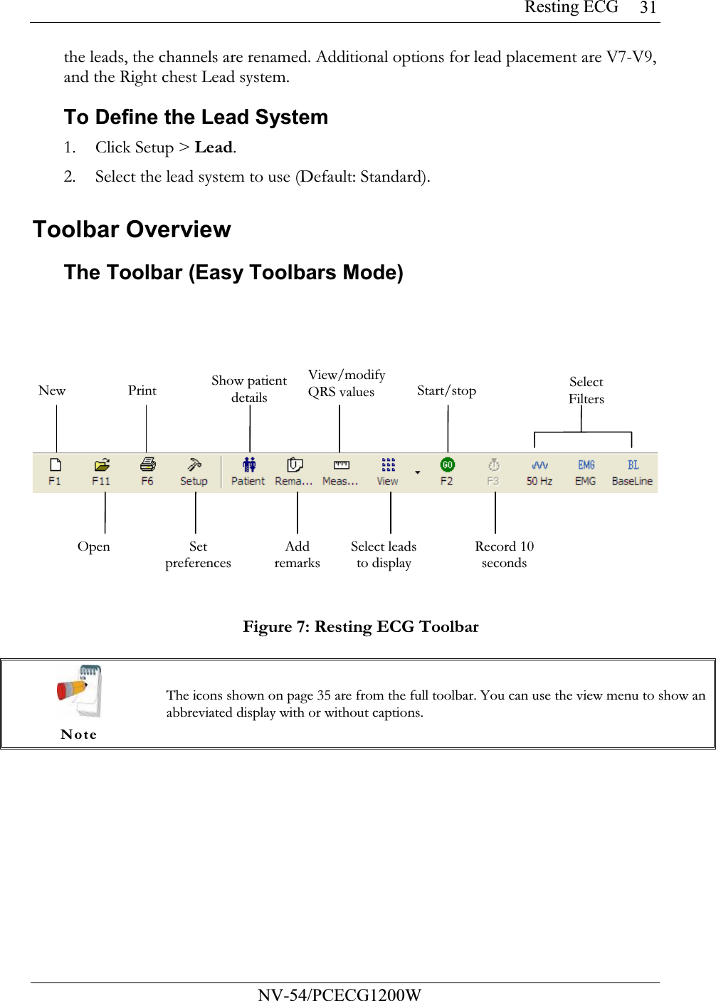
USERS MANUAL 1
Contents
1.
USERS MANUAL 1
2.
USERS MANUAL 2
3.
USERS MANUAL 3
USERS MANUAL 1
Navigation menu
Upload a User Manual
Namespaces
Wiki Guide
HTML
PDF
Info
Views
User Manual
Discussion / Help
Navigation