Norav Medical 1200WR WIRELESS ECG RECORDING SYSTEM User Manual PCECG1200WR Revised UserMan
Norav Medical Ltd. WIRELESS ECG RECORDING SYSTEM PCECG1200WR Revised UserMan
Contents
- 1. USERS MANUAL 1
- 2. USERS MANUAL 2
- 3. USERS MANUAL 3
USERS MANUAL 1

定䝬䪚䝰䝲䝲
ȶȶȶ
Instructions for Use and Technical Description
0473

ii Instructions for Use and Technical Description
Norav Users Guide
For Models: 1200W recorder; software versions: 5.0 and later
Copyright © Norav, March 08.
All rights reserved.
Document Number: NV-54/PCECG1200W
No part of this publication may be reproduced in any material form (including photocopying or storing it in any medium by
electronic means whether or not transiently or incidentally to some other use of this publication) without the prior written
permission of the copyright owner, or under the terms of a license issued by the copyright owner.
The information contained in this document is subject to change without notice. Norav is neither responsible for nor liable to
anyone in connection with this document.
Contact Information:
Norav Medical
2, Hamada St., P.O. Box 81, Yokneam, 20692, Israel
Telephone: +972 (04) 9893001
Fax: +972 (04) 9893004
Email: sales@norav.com
Standards Compliance
The interference generated by the device was tested according to the EMC 89/336/EEC
and found compliant with the standard.
The software complies with Standards for Analysis of Ventricular Late Potentials Using High
Resolution or Signal Averaged Electrocardiography, published in 1991 by the Task Force Committee
of the European Society of Cardiology, the American Heart Association, and the American College of
Cardiology.
The PC-ECG conforms to MDD 93/42 EEC Annex II, EC11 and EN 60601-2.
MDD authorized representative in Europe is:
Daniele Marangoni Dr. Eng. , Marangoni Consultants
Vicolo S. Franc. al Corso 4 Ang. Pontiere 11
37122 Verona Italy
phone +39 045 8030516, fax +39 045 8036028
mobile +39 335 290679, Email marangon@easynet.it
!
Caution
US Federal Law restricts this device to sale by, or on the order of, a physician
iii
The PC-ECG 1200W is tested and certified for the following standards:
EN60601/1: International
EN60601/2/25: International
EN60601/2/27: International
EN301 489-1; International
EN301 489-3; International
EN300 440; International
Protection type and class: CF
Defibrillation protection: Built in
Disclaimer
This system is intended as a decision support system for persons who have received
appropriate medical training, and should not be used as a sole basis for making clinical
decisions pertaining to patient diagnosis, care, or management. Any application of medical
information from the program, other than the original design or intended use thereof, is
not advised and considered a misuse of the software product.
Norav Limited Warranty
Norav products are warranted to be free from manufacturing and material defects for a
period of one (1) year from the date of shipment from Norav or the dealer to the original
purchaser.
Excluded from this warranty are expendable supply items including, but not limited to,
electrodes, lead wires, patient cables, and batteries. This warranty does not apply to any
product that Norav determines has been modified or damaged by the customer.
Except for the express warranties stated above, Norav disclaims all warranties including
implied warranties of merchantability and fitness. The stated express warranties are in lieu
of all obligations or liabilities on the part of Norav for damages, including but not limited
to, special, indirect, or consequential, arising out of or in connection with the use or
performance of Norav products.
Any action for breach of warranty shall be commenced within one (1) year of said breach
or be forever barred. Any repairs made to the product that are not covered by the
warranty shall be billed to the customer.
For service or technical support contact your local supplier or Norav Medical.

v
Table of Contents
CHAPTER 1: INTRODUCTION.......................................................................... 1
M
ANUAL
O
RGANIZATION
...........................................................................................................1
D
OCUMENT
C
ONVENTIONS
.......................................................................................................1
Notes and Cautions .....................................................................................................................1
Abbreviations and Acronyms .......................................................................................................2
Equipment Symbols .....................................................................................................................2
CHAPTER 2: OVERVIEW ....................................................................................3
P
ACKAGE
C
ONTENTS
..................................................................................................................3
P
ROGRAMS
.....................................................................................................................................4
PC-ECG
M
ODELS
........................................................................................................................4
I
NDICATIONS FOR
U
SE OF THE
PC-ECG
1200........................................................................5
ECG Intended Use......................................................................................................................5
Stress Testing Intended Use ..........................................................................................................5
C
ONTRAINDICATIONS FOR
U
SE AND
A
DVERSE
E
FFECTS
......................................................6
CHAPTER 3: SOFTWARE INSTALLATION ..................................................... 7
S
YSTEM
R
EQUIREMENTS AND
P
REREQUISITES
........................................................................7
Hardware ....................................................................................................................................7
I
NSTALLING OR
U
PDATING
T
HE
PC
S
OFTWARE
.....................................................................8
To Install PC-ECG 1200 ..........................................................................................................9
To Uninstall PC-ECG 1200....................................................................................................10
To Free Disk Space and Ensure Smooth Operation ...................................................................10
B
ACKING UP AND
R
ESTORING
S
ETUPS AND
P
ROTOCOLS
....................................................10
To Save Stress Test Setup ..........................................................................................................11
To Load Stress Test Setup .........................................................................................................11
To Save Stress Protocols .............................................................................................................11
To Load Stress Protocols ............................................................................................................12
To Set Preferences.......................................................................................................................12
CHAPTER 4: HARDWARE INSTALLATION.................................................. 13
S
AFETY
.........................................................................................................................................13
CLASSIFICATION OF THE EQUIPMENT ........................................................ 14
I
NSTALLING
M
ODEL
1200W.....................................................................................................15
To Connect Via USB................................................................................................................17
To Verify the Connections ..........................................................................................................18
To Perform Maintenance ............................................................................................................18
Calibration ................................................................................................................................19
C
ONNECTING AN
E
XERCISE
D
EVICE
......................................................................................19
To Connect an RS232 Controlled Treadmill/Ergometer ............................................................19
vi Instructions for Use and Technical Description
To Connect an Analog Controlled Treadmill/Ergometer............................................................ 19
Cabling ..................................................................................................................................... 19
To Determine Treadmill Cabling ............................................................................................... 19
C
ONNECTING A
B
LOOD
P
RESSURE
S
TRESS
M
ONITOR
......................................................... 20
To Connect a Blood Pressure stress Monitor ............................................................................... 20
CHAPTER 5: ACCESSORIES INSTALLATION ...............................................21
D/A
B
OARD
:
M
ODEL
:
CIO-DAC02
FOR
ISA
B
US
............................................................... 21
Jumpers Setting.......................................................................................................................... 21
Settings and Output of the D/A Board for 0-4 Volt Output .................................................... 21
Settings and Output of the D/A Board for -4 to +4 Volt Output ............................................ 22
To Continue Setup (After Installing the ISA Board/s).............................................................. 22
PCI
B
US
B
OARD
F
UNCTIONING AS AN
ECG
T
RIGGER
....................................................... 23
To Set Up an ECG Trigger via PCI Bus Board ....................................................................... 23
To Complete Setup .................................................................................................................... 23
Cable for PCI board.................................................................................................................. 23
I
NSTALLATION OF THE
TANGO
A
UTOMATIC
BP
U
NIT
..................................................... 24
To Verify that the Driver is Installed Correctly .......................................................................... 24
To Update the Driver ................................................................................................................ 24
Connecting TANGO Automatic BP Unit................................................................................ 24
To Set Up PC-ECG Software .................................................................................................. 25
To Set Up Tango Unit.............................................................................................................. 25
CHAPTER 6: PATIENT PREPARATION .........................................................27
CHAPTER 7: RESTING ECG .............................................................................29
Q
UICK
S
TART
............................................................................................................................. 30
To Perform a New Test ............................................................................................................. 30
Operation with Function Keys.................................................................................................... 30
R
ESTING
12
L
EAD
ECG ........................................................................................................... 30
L
EADS
P
LACEMENT
................................................................................................................... 30
To Define the Lead System........................................................................................................ 31
T
OOLBAR
O
VERVIEW
................................................................................................................ 31
The Toolbar (Easy Toolbars Mode)........................................................................................... 31
R
ESTING
ECG
S
ETUP
............................................................................................................... 32
T
OOLBAR AND
M
ENUS
.............................................................................................................. 35
U
SING THE
M
ATLAB
F
EATURE WITHIN
PC-ECG
1200 ....................................................... 39
Example of ECG Display with MATLAB............................................................................. 40
CHAPTER 8: STRESS ECG .................................................................................41
To Customize the Display ......................................................................................................... 41
To Lock Screen Window Borders............................................................................................... 41
Q
UICK
S
TART
............................................................................................................................. 42
To Perform a New Test ............................................................................................................. 42
To Print an ECG..................................................................................................................... 42
To Print a Report...................................................................................................................... 42
vii
L
EADS
P
LACEMENT
....................................................................................................................43
To Define the Lead System.........................................................................................................43
O
PERATION WITH
F
UNCTION
K
EYS
........................................................................................43
T
OOLBAR
O
VERVIEW
................................................................................................................44
Main Toolbar (Easy Toolbars Mode).........................................................................................44
Stress Test Commands ...............................................................................................................44
Views and Filters Toolbar .........................................................................................................45
Average Viewer Toolbar ............................................................................................................45
Post Processing Options Toolbar .................................................................................................46
S
TRESS
ECG
S
ETUP
....................................................................................................................47
T
OOLBAR AND
M
ENUS
:
M
AIN
..................................................................................................52
T
OOLBAR AND
M
ENUS
:
S
TRESS
T
EST
C
OMMANDS
...............................................................53
T
OOLBAR AND
M
ENUS
:
A
VERAGE
V
IEWER
...........................................................................54
T
OOLBAR AND
M
ENUS
:
P
OST
P
ROCESSING
............................................................................54
To Start the Stress Recording Program........................................................................................55
To Start a New Test..................................................................................................................55
Recovery Phase ...........................................................................................................................56
V
IEWING
R
ESULTS
.....................................................................................................................56
To View Study Results ..............................................................................................................57
To Display the Review Screen Automatically ..............................................................................57
To Display the Review Screen Manually.....................................................................................57
To Save Study Results................................................................................................................57
M
ETABOLIC
S
TRESS
E
STIMATION
(METS).............................................................................58
T
RANSFER
F
ILE
“T
RNSF
.
TXT
”..................................................................................................58
To Transfer a File......................................................................................................................58
A
DDITIONAL
F
EATURES
............................................................................................................59
To Define Max. HR.................................................................................................................59
To Define Worst ST..................................................................................................................59
RS232
C
ONTROLLED
T
READMILL
T
YPES
...............................................................................60
RS232
C
ONTROLLED
B
ICYCLE
E
RGOMETERS
.......................................................................61
CHAPTER 9: LATE POTENTIAL SIGNAL AVERAGING ............................. 63
Q
UICK
S
TART
..............................................................................................................................64
To Start a New Test..................................................................................................................64
To Print.....................................................................................................................................64
O
PERATION WITH
F
UNCTION
K
EYS
........................................................................................65
L
EADS
...........................................................................................................................................65
LP
S
IGNAL
A
VERAGING
S
ETUP
................................................................................................66
T
OOLBAR AND
M
ENUS
..............................................................................................................68
I
NTERPRETING
R
ESULTS
...........................................................................................................70
Numerical Results......................................................................................................................71
CHAPTER 10: MONITORING ............................................................................ 73
Q
UICK
S
TART
..............................................................................................................................74
To Start a New Test..................................................................................................................74
viii Instructions for Use and Technical Description
To Print .................................................................................................................................... 74
Print Study (print a selected time range and leads) ...................................................................... 74
M
ONITORING
ECG
S
ETUP
....................................................................................................... 74
T
OOLBAR AND
M
ENUS
.............................................................................................................. 77
CHAPTER 11: HEART RATE VARIABILITY (HRV) ........................................79
Q
UICK
S
TART
............................................................................................................................. 80
To Start a New Test ................................................................................................................. 80
To Print an HRV Report......................................................................................................... 80
To Print an ECG..................................................................................................................... 81
HRV
S
ETUP
................................................................................................................................81
S
TARTING A
S
TUDY
................................................................................................................... 83
To Add or Subtract an Interval................................................................................................. 83
To Edit Interval Names............................................................................................................ 83
To Import or Save GDT/BDT Format.................................................................................... 83
R
ESULTS
D
ISPLAY
...................................................................................................................... 84
HRV
I
NTERVAL
M
EASUREMENT
............................................................................................. 84
CHAPTER 12: MEASUREMENTS/ INTERPRETATION................................85
Q
UICK
S
TART
............................................................................................................................. 86
To Start Measurements.............................................................................................................. 86
To Print Reports ....................................................................................................................... 86
P
ERFORMING
C
HANGES IN
C
ALCULATIONS
.......................................................................... 86
To Move the QRS Marker........................................................................................................ 86
To Add or Remove a Wave Marker.......................................................................................... 86
To Move the Wave Marker ....................................................................................................... 87
F
EATURES
................................................................................................................................... 87
To View the Measurements on a QRS ...................................................................................... 87
To View the Measurements on a Channel.................................................................................. 87
To View the Measurements on All Channels for QT................................................................. 87
T
ABULAR
S
CREEN
...................................................................................................................... 87
A
VERAGES
D
ISPLAY
.................................................................................................................. 88
QRS
D
ISPLAY
............................................................................................................................. 89
T
OOLBAR OF
A
VERAGES
/QRS
D
ISPLAYS
.............................................................................. 90
C
ALIPER
D
ISPLAY
...................................................................................................................... 91
Toolbar of Caliper Display ........................................................................................................ 91
T
OOLBAR AND
M
ENUS
.............................................................................................................. 92
CHAPTER 13: DATABASE APPLICATION........................................................95
First Time Use.......................................................................................................................... 96
C
OMPARING
R
EST
T
ESTS
.......................................................................................................... 97
To Compare Rest Tests.............................................................................................................. 97
D
ATABASE
S
ETUP
...................................................................................................................... 98
T
OOLBAR AND
M
ENUS
.............................................................................................................. 98
APPENDIX A: INTERFACING WITH INFORMATION SYSTEMS.............. 101
ix
D
EMOGRAPHIC
D
ATA
............................................................................................................. 101
HL7
F
ORMAT
F
ILE
.................................................................................................................. 103
GDT/BDT
T
YPE
C
OMMUNICATION
................................................................................... 105
S
AVING THE
S
TRESS
T
EST AS A
RAW
D
ATA
(“
NATIVE BINARY
”)
F
ORMAT
F
ILE
........... 106
S
AVING THE
M
ONITOR
T
EST AS A
R
AW
D
ATA
(“N
ATIVE
B
INARY
”)
F
ORMAT
F
ILE
..... 107
APPENDIX B: TECHNICAL SPECIFICATIONS.............................................108
1200W (TRANSMITTER).......................................................................................108
1200WR (RECEIVER).............................................................................................110
APPENDIX C: REPORT SAMPLES.................................................................... 111
APPENDIX D: TROUBLESHOOTING ..............................................................116
USB
D
RIVER IS NOT
I
NSTALLED
P
ROPERLY ON
W
INDOWS
XP
D
URING
PC-ECG
I
NSTALLATION
......................................................................................................................... 116
Problem................................................................................................................................... 116
Solution .................................................................................................................................. 116
R
ECOVERING
ECG
D
ATA AFTER
U
NEXPECTED
S
HUTDOWN OF THE
S
TRESS
A
PPLICATION
........................................................................................................................... 117
Problem................................................................................................................................... 117
Solution .................................................................................................................................. 117
W
ORKING IN
A
UTO
S
AVE
M
ODE
W
ITHOUT
S
AVING
M
ODIFICATIONS
........................... 117
A
T
HICK
S
TRAIGHT
L
INE IS
D
ISPLAYED
F
OR
A
LL
L
EADS
................................................ 118
Problem................................................................................................................................... 118
Solution .................................................................................................................................. 118
N
OISY
ECG
S
IGNAL ON
L
EADS
............................................................................................ 118
Problem................................................................................................................................... 118
Solution .................................................................................................................................. 118
M
ISSING DATA AFTER A THICK LINE
.................................................................................... 119
Problem................................................................................................................................... 119
Solution .................................................................................................................................. 119

x Instructions for Use and Technical Description
List of Figures
F
IGURE
1:
S
AVING
S
TRESS
S
ETUP
....................................................................................11
F
IGURE
2:
PC-ECG
1200W.............................................................................................15
F
IGURE
3:
USB
C
ABLE
....................................................................................................16
F
IGURE
4:
1200
WR
R
ECEIVER
.......................................................................................18
F
IGURE
5:
E
LECTRODE
P
LACEMENT
................................................................................27
F
IGURE
6:
R
ESTING
ECG
M
AIN
S
CREEN
.........................................................................29
F
IGURE
7:
R
ESTING
ECG
T
OOLBAR
................................................................................31
F
IGURE
8:
S
TRESS
ECG
R
ESULTS
S
CREEN
......................................................................41
F
IGURE
9:
M
AIN
S
TRESS
T
OOLBAR
.................................................................................44
F
IGURE
10:
S
TRESS
T
EST
C
OMMANDS
T
OOLBAR
.............................................................44
F
IGURE
11:
S
TRESS
ECG
V
IEWS AND
F
ILTERS
T
OOLBAR
................................................45
F
IGURE
12:
S
TRESS
ECG
P
OST
P
ROCESSING
D
ISPLAY
T
OOLBAR
....................................45
F
IGURE
13:
S
TRESS
ECG
P
LAYBACK
T
OOLBAR
..............................................................46
F
IGURE
14:
C
HANGE
T
EST
P
ROTOCOL
.............................................................................55
F
IGURE
15:
P
ATIENT
D
ATA
E
NTRY
..................................................................................56
F
IGURE
16:
L
ATE
P
OTETIAL
S
IGAL
A
VERAGIG
S
CREE
.......................................63
F
IGURE
17:
LP
S
IGNAL
A
VERAGING
R
EVIEW
S
CREEN
.....................................................70
F
IGURE
18:
M
ONITORING
S
CREEN
...................................................................................73
F
IGURE
19:
HRV
R
ESULTS
..............................................................................................84
F
IGURE
20:
M
EASUREMENTS
—T
ABULAR
S
CREEN
..........................................................85
F
IGURE
21:
M
EASUREMENTS
—A
VERAGES
D
ISPLAY
.......................................................88
F
IGURE
22:
M
EASUREMENTS
—QRS
DISPLAY
.................................................................89
F
IGURE
23:
T
OOLBAR OF
A
VERAGES
/QRS ......................................................................90
F
IGURE
24:
M
EASUREMENTS
—C
ALIPER
.........................................................................91
F
IGURE
25:
T
OOLBAR OF
C
ALIPER
...................................................................................91
F
IGURE
26:
D
ATABASE
M
AIN
S
CREEN
.............................................................................95
F
IGURE
27:
D
ATABASE
P
ATIENT
Q
UERY
.........................................................................96
F
IGURE
28:
D
ATABASE
P
ROPERTIES OF
S
ELECTED TEST
..................................................97
F
IGURE
29:
R
EST
R
EPORT
..............................................................................................111
F
IGURE
30:
S
TRESS
A
PPLICATIONS
-
C
OMPREHENSIVE
R
EPORT
....................................112
F
IGURE
31:
ECG
M
ONITORING
R
EPORT
........................................................................113
F
IGURE
32:
H
EART
R
ATE
V
ARIABILITY
R
EPORT
...........................................................114
F
IGURE
33:
L
ATE
P
OTENTIAL
R
EPORT
...........................................................................115

xi
List of Tables
T
ABLE
1:
M
INIMUM
C
OMPUTER
C
ONFIGURATION
............................................................ 7
T
ABLE
2:
P
RINTERS
I
NSTALLATION
R
EQUIREMENTS
......................................................... 8
T
ABLE
3:
P
ROGRAM
I
CONS
............................................................................................... 9
T
ABLE
4:
D/A
B
OARD
0
TO
+4
V
OLT
............................................................................... 21
T
ABLE
5:
D/A
B
OARD
–4
TO
+4
V
OLT
............................................................................ 22
T
ABLE
6:
O
PERATION WITH
F
UNCTION
K
EYS
................................................................. 30
T
ABLE
7:
R
ESTING
ECG
S
ETUP
O
PTIONS
....................................................................... 35
T
ABLE
8:
R
ECORDING
R
ESTING
ECG ............................................................................. 39
T
ABLE
9:
S
TRESS
F
UNCTION
K
EYS
................................................................................. 43
T
ABLE
10:
S
TRESS
ECG
S
ETUP
O
PTIONS
........................................................................ 51
T
ABLE
11:
M
AIN
S
TRESS
T
OOLBAR AND
M
ENUS
............................................................ 52
T
ABLE
12:
S
TRESS
T
EST
C
OMMANDS
............................................................................. 53
T
ABLE
13:
A
VERAGE
V
IEWER
T
OOLBAR
........................................................................ 54
T
ABLE
14:
P
OST
P
ROCESSING
T
OOLBAR AND
M
ENUS
..................................................... 55
T
ABLE
15:
T
RANSFER
F
ILE
F
ORMAT
............................................................................... 58
T
ABLE
16:
C
ONTROLLED
T
READMILLS
........................................................................... 60
T
ABLE
17:
C
ONTROLLED
E
RGOMETERS
.......................................................................... 61
T
ABLE
18:
LP
S
IGNAL
A
VERAGING
F
UNCTION
K
EYS
..................................................... 65
T
ABLE
19:
LP
S
IGNAL
A
VERAGING
L
EADS
P
LACEMENT
................................................ 65
T
ABLE
20:
LP
S
IGNAL
A
VERAGING
S
ETUP
..................................................................... 67
T
ABLE
21:
LP
S
IGNAL
A
VERAGING
T
OOLBAR AND
M
ENUS
............................................ 69
T
ABLE
22:
LP
S
IGNAL
A
VERAGING
N
UMERICAL
R
ESULTS
............................................. 71
T
ABLE
23:
M
ONITORING
S
ETUP
O
PTIONS
....................................................................... 76
T
ABLE
24:
M
ONITORING
T
OOLBAR AND
M
ENUS
............................................................ 78
T
ABLE
25:
HRV
S
CREEN
................................................................................................ 80
T
ABLE
26:
M
EASUREMENTS
T
OOLBAR AND
M
ENUS
....................................................... 94
T
ABLE
27:
D
ATABASE
S
ETUP
O
PTIONS
........................................................................... 98
T
ABLE
28:
D
ATABASE
T
OOLBAR AND
M
ENUS
.............................................................. 100
T
ABLE
29:
S
TRESS
R
AW
D
ATA
F
ILE
F
ORMAT
............................................................... 106
T
ABLE
30:
M
ONITOR
R
AW
D
ATA FILE FORMAT
............................................................ 107
Introduction
NV-54/PCECG1200W
1
CHAPTER 1: INTRODUCTION
Manual Organization
This manual explains in detail how to install and use the PC-ECG 1200.
At the beginning of each application chapter, there is a Quick Start section, which is
a brief explanation of how to carry out a study, including the keyboard short-cuts for
the main functions. If you are familiar with ECG procedures, you can use this Quick
Start section to get up and running quickly.
The software must be installed before the hardware. See Software Installation, page 7
and Hardware Installation, page 13.
Document Conventions
Notes and Cautions
Pay particular attention at specific points in a procedure when one of the following
messages appears:
WARNING
Warnings call attention to possible hazards involving potential damage or injury to
persons.
!
Caution
Cautions refer to practices necessary to protect against potential damage or loss to
equipment. Pay careful attention to instructions.
Note
Notes provide pertinent information to help obtain optimum performance from
the software or signify an important step or procedure that requires special
attention.
Instructions for Use and Technical Description
Norav Medical Ltd.
2
Abbreviations and Acronyms
Abbreviation Meaning
BP Blood pressure
ECG Electrocardiogram
Database Database application
HRV Heart Rate Variability
ID Identification
LP Late Potential
LQTS Long QT Syndrome
METS Metabolic Stress Estimation
SN Serial Number
USB Universal Serial Bus
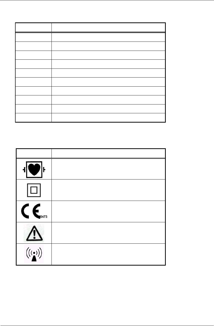
Equipment Symbols
Symbol Description
Defibrillated CF type equipment
Class II equipment
Complies with the Medical Device Directive of the
European Union
Attention, consult ACCOMPANYING
DOCUMENTS
Non-ionizing radiation.

Overview
NV-54/PCECG1200W
3
CHAPTER 2: OVERVIEW
Package Contents
The PC-ECG 1200W package contains the following elements:
• Wireless Acquisition box PCECG1200W (page 15)
• Patient leads
• USB cable
• 1200WR Receiver
• Antenna
• Software CD with the PC-ECG 1200 installation package, including:
◊ Rest
◊ Stress
◊ Monitor
◊ HRV
◊ LP
◊ Database
• Software key (if optional software is included)

Instructions for Use and Technical Description
Norav Medical Ltd.
4
Programs
Each program has a specific purpose. The following is a brief description of when to
use each one:
Rest Records and measures short ECG tests on patients in resting position (up to 10
seconds)
Stress
Records and measures ECG tests on patients under stress conditions using a pre-
defined test protocol. The stress test includes 3 basic stages:
• Rest
• Stress
• Recovery
Each stage may be divided into more than one phase according to the testing
protocol used.
Monitor Works with an ECG device to record, monitor and save a prolonged ECG test in
rest condition
HRV Tests according to time how patient pulse and heart rate varies with load,
medication, etc.
LP Predicts tendency to ventricular tachycardia
Database ECG Database Management System. Manages patients and ECG tests details.
PC-ECG Models
1200 W Wireless ECG Recording test during stress and rest condition (attached to
patient’s body)

Overview
NV-54/PCECG1200W
5
Indications for Use of the PC-ECG 1200
ECG Intended Use
ECG is intended to disclose either normal condition or patterns of arrhythmia,
myocardial ischemia, rate abnormalities, or features of prognostic value in the
following cases:
◊ Patients with suspected cardiac abnormalities
◊ Populations of patients at an age or period in which a routine baseline
evaluation of ECG characteristics is desired.
QT Analysis is useful in the assessment of long QT syndrome (LQTS). In some
instances, LQTS can be corrected by pharmacological therapy. QT analysis is also
used to measure QT dispersion, the difference between maximal and minimal QT
values. QT dispersion is a measure of the inhomogeneity of ventricular repolarization.
The PC ECG 1200 has been tested to measure Heart Rate Variability to within 1
millisecond tolerance. The clinical significance of Heart Rate Variability measures
should be determined by a physician.
The PC ECG 1200 has been tested to measure Late Potential to a tolerance of within
1 millisecond, and 1 microvolt. The clinical significance of Late Potential measures
should be determined by a physician.
Stress Testing Intended Use
Angina pectoris (chest pain) is a clinical syndrome resulting from myocardial ischemia,
indicative of reduced blood supply to the cardiac muscle. The electrocardiogram may
establish the diagnosis of ischemic heart disease if characteristic changes are present.
Stress testing is the most widely used method to decide whether this chest pain is
related to myocardial ischemia, and thus to coronary artery disease. In stress testing,
the contractile capability of the heart muscle is monitored via ECG during patient
exercise. Patients exercise by bicycle, treadmill, or other means, while the ECG is
monitored continuously. Exercise loads are determined by predefined protocols. The
ECG signals are recorded for the resting, exercise, and recovery phase portions of the
exercise protocol. The changes in ECG waveforms are compared to the resting ECG
records. Most of the commercial stress test systems control the bicycle or treadmill
automatically according to the requirements of the chosen protocol, although this is
not essential.
ST segment monitoring is intended as an aid in the evaluation of myocardial ischemia
in patients with known or suspected coronary artery disease. The ST segment
algorithm has been tested for accuracy of the ST segment data, and a database is used
as a tool for performance testing.
The significance of the ST segment changes must be determined by a physician.

Instructions for Use and Technical Description
Norav Medical Ltd.
6
Contraindications for Use and Adverse Effects
The device has no contraindications or adverse events.

Software Installation
NV-54/PCECG1200W
7
CHAPTER 3: SOFTWARE
INSTALLATION
System Requirements and Prerequisites
Hardware
Note
Stress application with real-time printout is resource intensive.
To optimize performance, we recommend that you disable “Start Up” programs to
free system resources. For instructions, see Windows help.
Note
The PC should not be set up to work under saving power conditions. Do not
enable PC sleep mode (standby), hibernate, or turning off the hard disk while
running an ECG test.
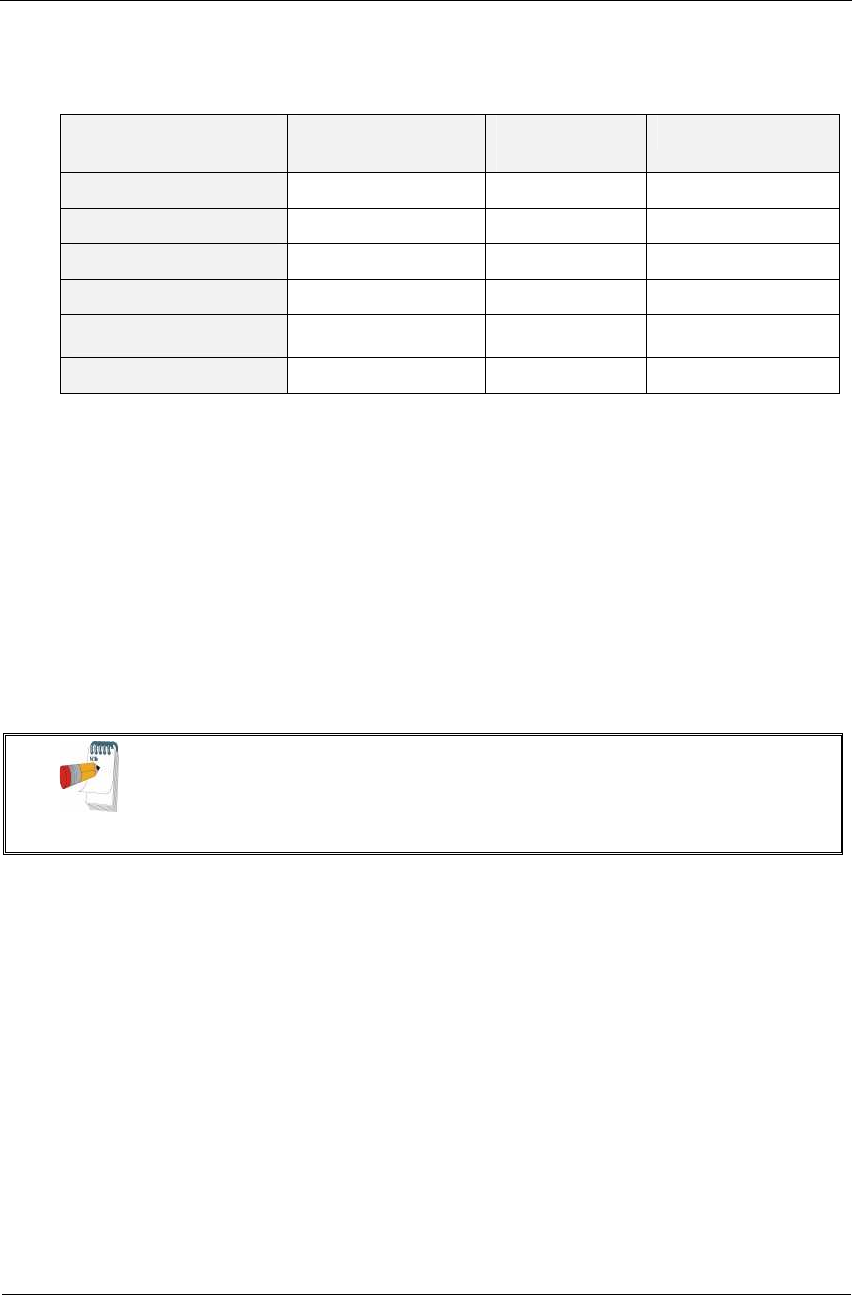
PC Minimum Configuration
Application CPU Speed
(MHz)
RAM Memory
(MB)
Disk Space (GB) Number
of Free
RS232 or
USB Ports
Rest 100 32 2 1
Monitoring
Application 200 32 4 1
LP 450 128 2 1
HRV 450 128 2 1
Database 200 64 8 1
Stress 1000 128 20 2
Stress + R
trigger 1300 128 20 2
Stress + Blood
pressure
monitor
1500 128 20 3
Table 1: Minimum Computer Configuration
Instructions for Use and Technical Description
Norav Medical Ltd.
8
Installing Printers
Application Technology RAM Memory
(MB)
Driver
Rest LASER/INK 2 Vendor / MS
Monitoring Application LASER/INK 2 Vendor / MS
LP LASER/INK 2 Vendor / MS
HRV LASER/INK 2 Vendor / MS
Database LASER/INK 2 Vendor / MS
Stress Fast LASER 8 MS
Table 2: Printers Installation Requirements
Installing the Thermal Printer
Use a 4 inch or 8 inch thermal printer. The thermal printer driver is installed
separately from the PC-ECG 1200 program.
A thermal printer can be supplied by Norav (MP200, 8 inch). This printer requires the
purchase of a dongle with P1 license permission. The MP200 driver is available on the
PC-ECG 1200 CD at the following path: "<CD>:\MP200\OEMPRINT.inf"
.
Installing or Updating The PC Software
Note:
Install the software before installing the hardware. If the device is connected to the
PC, disconnect the device before installing the software.
The software package works under Windows NT, 98, ME, 2000, and XP operating
systems.

Software Installation
NV-54/PCECG1200W
9
To Install PC-ECG 1200
1. Insert the CD in the drive.
The installation program starts automatically.
2. Follow the instructions on-screen.
0.
After you have completed installation, a group icon called PC-ECG 1200 is added to
the desktop. Double-click the group icon to display the following program icons:
Note:
Icons are displayed only for those programs for which you have purchased the
license
Icon Explanation
Heart Rate Variability
Late Potential Signal Averaging
Monitoring
Resting ECG
Stress Test
Database application
Table 3: Program Icons
Resting ECG is the basic software package. It does not require a software key.
The following are optional and require software keys:
◊ Measurement and interpretation functions for Resting ECG

Instructions for Use and Technical Description
Norav Medical Ltd.
10
◊ ECG Database
◊ Heart Rate Variability
◊ Late Potential
◊ Monitoring
◊ Stress Test
You can activate optional packages that have no key by selecting Simulator in Setup
(see Simulator ECG, Page 32).
If you have purchased the S2 remote viewing, install the Remote View program from
the Remote View directory on the CD. This program enables a remote viewer for an
ECG study. The image is displayed in JPEG format.
To Uninstall PC-ECG 1200
New Version Replacing Old Version
There is no need to remove the previous installation. The existing setup will remain
for the new version.
If the new software version does not operate properly, remove the old installation (see
Old Version Replacing New Version, below) and then remove the old existing setup as
follows:
Start Run Type regedit OK Choose HKEY_CURRENT_USER
Software NORAV MEDICAL Edit Delete
Old Version Replacing New Version
Uninstall the existing version as follows:
My Computer Control Panel Add/Remove Programs PC-ECG 1200
Add/Remove OK
To Free Disk Space and Ensure Smooth Operation
Windows provides utilities to delete superfluous files, and to defragment the disk.
Refer to Windows help for instructions on using Disk Cleanup and Defragment.
Backing up and Restoring Setups and Protocols
When you reinstall or upgrade PC-ECG 1200, the program overwrites your existing
configurations and protocols.
To save the configuration data for stress application, follow these procedures:

Software Installation
NV-54/PCECG1200W
11
To Save Stress Test Setup
1. Start Stress ECG.
2. Click View\Save Setup (see Figure 1).
Figure 1: Saving Stress Setup
3. Name the file.
4. Provide a location in which to save the file and Click OK.
To Load Stress Test Setup
1. Start Stress ECG.
2. Click View\Load Setup.
3. Click Browse and find the location in which the file is saved.
4. Select the file (with the name you gave it and the suffix ‘STF’) and click
OK.
To Save Stress Protocols
1. Create a new directory in C:\My Documents, with a name like
PcBackup.
2. Copy file StWorked.mdb from the directory where PC-ECG is
installed (normally C:\Program Files\PC-ECG).
3. Paste it into a backup directory (e.g., C:\My Documents\PcBackup).

Instructions for Use and Technical Description
Norav Medical Ltd.
12
To Load Stress Protocols
1. Copy the file StWorked.mdb from the directory where you saved it
(e.g., C:\My Documents\PcBackup).
2. Paste it into the directory where PC-ECG is installed (normally
C:\Program Files\PC-ECG).
A window is displayed, asking you if you would like to replace the
existing file.
3. Click Yes.
To Set Preferences
1. After installing the PC-ECG 1200 package, and prior to operation, click
Setup to tailor your preferences.
2. Begin with Environment, which configures the hardware.
3. Continue with the other tabs in any order.

Hardware Installation
NV-54/PCECG1200W
13
CHAPTER 4: HARDWARE
INSTALLATION
Safety
WARNING
The PC-ECG 1200W transmitter uses battery power supply. PCECG1200WR
receiver uses Power supply via USB port. It is also sensitive to electrical
interference.
The PC-ECG 1200 controls exercise machines.
To prevent possible injury, read this page carefully prior to installing the device.
• A patient undergoing a test must be at a distance of at least:
1.5 meters from the computer, printer and other peripherals,
• If such conditions cannot be fulfilled, the entire system needs to be connected
to the A/C power supply through an Isolation transformer meeting the
EN60601/1 standard.
• Use only the recommended battery type as instructed in the technical
specifications to operate the PCECG1200W (4 - AA alkaline or NIMH
rechargeable
)
.
• Do not use batteries with expired dates.
• Remove batteries form the PCECG1200W when it is not in use.
• Any treadmill used with the PC-ECG 1200 must contain a manual control in
order to allow the user to stop the operation of the treadmill in case of
emergency.
• In the event of apparent changes in the performance of the device, discontinue
use immediately. Do not resume use until the device is approved by the
manufacturer or by a representative of the manufacturer.
• If audio is playing on the PC, the ECG shows interference. Do not run an
audio CD on the PC while running an ECG test via the USB connection.
• Defibrillation protection is built in for Model W.
• Operate the unit only at clinics and hospitals. Do not use at home.
• Operation only by trained medical staff.
Instructions for Use and Technical Description
Norav Medical Ltd.
14
This device complies with Part 15 of the FCC Rules. Operation is subject to the
following two conditions:
(1) This device may not cause harmful interference and
(2) This device must accept any interference received, including interference that
may cause undesired operation.
Note
The manufacturer is not responsible for any Radio or TV interference
caused by unauthorized modifications to this equipment. Such
modifications could void the user’s authority to operate the equipment.
Note
Install hardware only after software installation.
CLASSIFICATION OF THE EQUIPMENT
- According to the type of protection against electric shock:
INTERNALLY POWERED EQUIPMENT
- According to the degree of protection against electric shock:
TYPE CF APPLIED PART
- According to the degree of protection against ingress of water:
ORDINARY EQUIPMENT
- According to the degree of safety of application in the presence of a
flammable anaesthetic mixture with air or with oxygen or nitrous oxide:
EQUIPMENT NOT SUITABLE FOR USE IN THE PRESENCE OF A
FLAMMABLE ANAESTHETIC MIXTURE WITH AIR OR WITH OXYGEN
OR NITROUS OXIDE.
- According to the mode of operation: CONTINUOUS OPERATION
Hardware Installation
NV-54/PCECG1200W
15
Installing Model 1200W
The PC-ECG 1200W kit contains the following items:
◊ Acquisition box (see Figure 2, below)
◊ Patient leads
◊ USB cable (see Figure 3, page 16)
◊ Antenna
◊ 1200 WR receiver (see Figure 4, page 18)
◊ Software CD of PC-ECG 1200 installation package.
◊ Software key (if optional software is included)
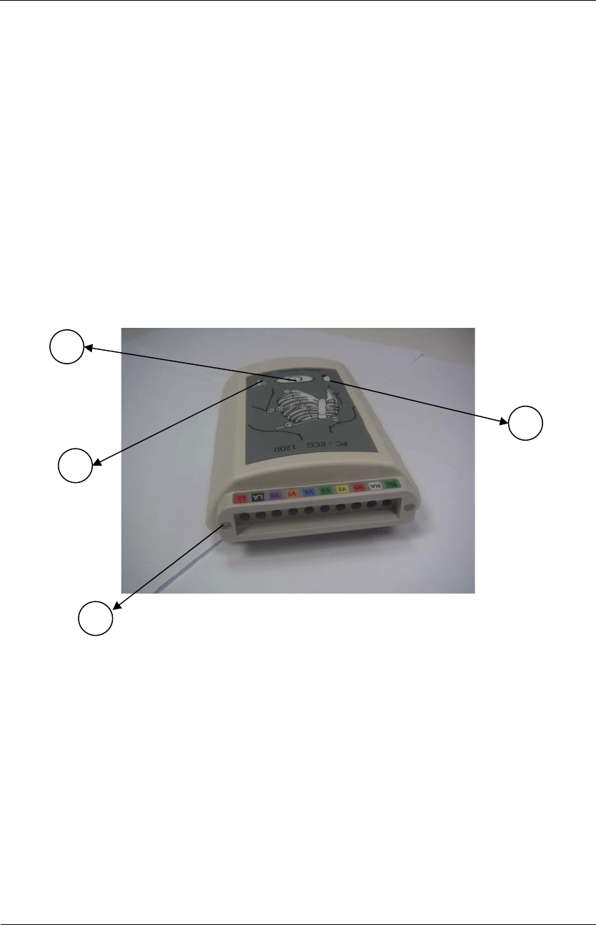
Figure 2: PC-ECG 1200W
1
2
3
4
Instructions for Use and Technical Description
Norav Medical Ltd.
16
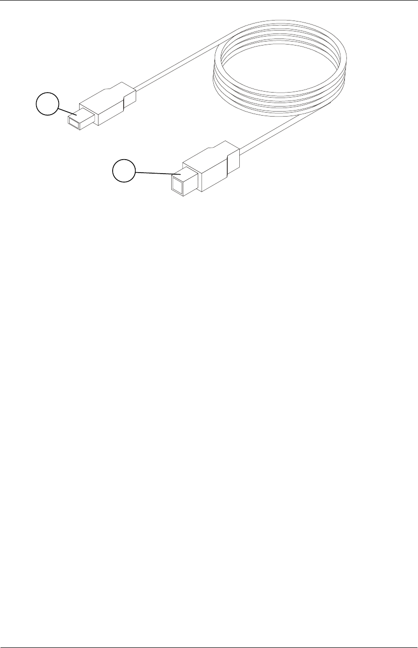
Figure 3: USB Cable
1
2

Hardware Installation
NV-54/PCECG1200W
17
To Connect Via USB
!
Caution
Make sure the device is switched off Cautions refer to practices necessary to
protect against potential damage or loss to equipment.
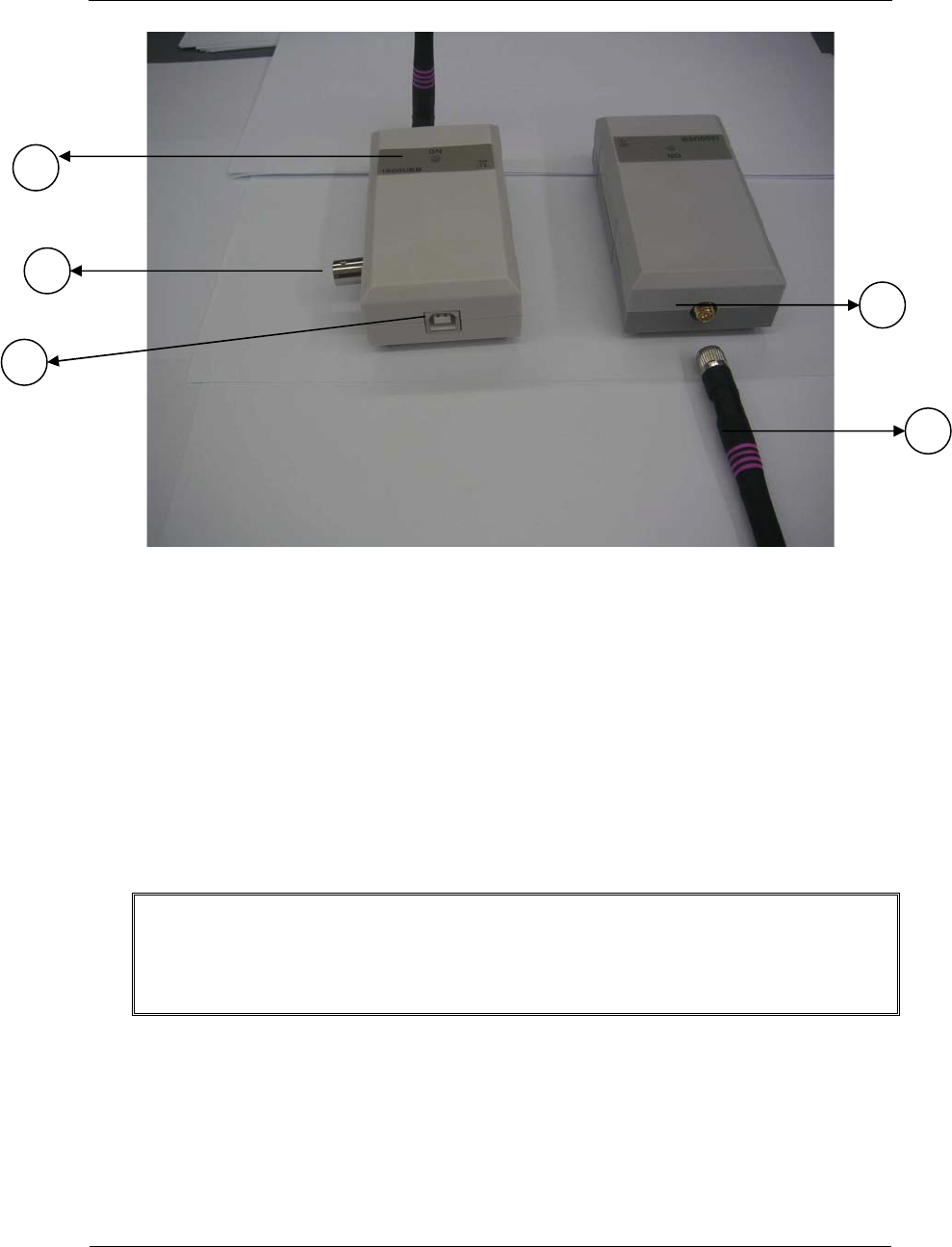
1. Connect Antenna (Figure 4, Page 18, detail 4) to the connector on
1200WR Receiver (Figure 4, Page 18, detail 2).
2. Connect the A-type connector of the USB cable (Figure 3, Page 16,
detail 1) to the PC.
3. Connect the B-type connector of the USB cable (Figure 3, Page 16,
detail 2) to the input of the 1200WR Receiver (Figure 4, Page 18,
detail 1).
4. A wizard for installing new hardware driver appears. Follow the
instructions. If working under Windows XP press “Continue anyway”
on message regarding the digital signature (each time it appears). After
the driver is installed make sure the green light is illuminated on the
1200 WR Receiver (Figure 4, Page 18, detail 3)
5. Insert 4 - AA alkaline or NIMH rechargeable batteries into the battery
compartment of the PCECG1200W unit.
6. Switch on the PC-ECG 1200W (Figure 2, Page 15, detail 2) and verify
that the ON light is illuminated Figure 2, Page 15, detail 3).
7. Connect the 10 patient leads according to the lables to the 10
connectors of the PC-ECG 1200W (Figure 2, Page 15, detail 1).
8. If the optional software key is included, connect it to the parallel port
of the computer.
9. If a printer is connected via the parallel port, plug the printer cable
into the key.
The optional BNC output (Figure 4, Page 18, detail 5) is a trigger control for
connecting to an external device, such as an ergometer or the Tango unit.
Instructions for Use and Technical Description
Norav Medical Ltd.
18
Figure 4: 1200 WR Receiver
To Verify the Connections
1. Connect the PC-ECG 1200W to the patient.
2. Connect the electrode leads to the electrodes, starting with RL.
3. Verify that an ECG is acquired and displayed on the screen.
To Perform Maintenance
!
Caution
The device is not waterproof. Do not expose the device to water or any kind of
liquid. Maintain in a dry place.
1. Use alcohol pads to clean the device of moisture and hairs.
2. Replace the pouch or wash it at 30
0
C.
3
5
1
2
4

Hardware Installation
NV-54/PCECG1200W
19
Calibration
The device does not need any calibration.
Connecting an Exercise Device
You can connect a treadmill or ergometer to the computer independently of the
PC-ECG 1200W. You can also operate the exercise device without using an ECG
recorder by using the software with Simulator option selected.
To Connect an RS232 Controlled Treadmill/Ergometer
Connect the RS232 cable (as specified by the vendor) to COM 2 (if COM 2 is in
use, then wait until the software has been installed and use the assigned COM port).
To Connect an Analog Controlled Treadmill/Ergometer
A digital/analog converter (D/A) board converts the digital signal from the
computer into an analog signal that the treadmill or ergometer can read.
1. Insert the D/A board into the PC.
2. Connect the cable from the D/A board as specified in the D/A board
table.
Cabling
The RS232 cable should contain at least 3 wires: TD, RD using pin 2 and 3 and
GROUND using pin 5.
Straight type means that pin 2 on the PC side connects to pin 2 on the exercise
device side, pin 3 on the PC side connects to pin 3 on the exercise device side, and
pin 5 on the PC side connects to pin 5 on the exercise device side.
Crossed type means that pin 2 on the PC side connects to pin 3 on the exercise
device side, pin 3 on the PC side connects to pin 2 on the exercise device side and
pin 5 on the PC side connects to pin 5 on the exercise device side.
To Determine Treadmill Cabling
Check which pins are assigned for TD and RD on the exercise device connector.
• If pin 2 is RD and pin 3 is TD, then the exercise device requires a
crossed cable
• If pin 2 is TD and pin 3 is RD, then the exercise device requires a
straight cable.

Instructions for Use and Technical Description
Norav Medical Ltd.
20
Connecting a Blood Pressure Stress Monitor
To Connect a Blood Pressure stress Monitor
1. Insert the D/A board into the PC and connect the cable from the
D/A board to the BNC input on the monitor.
2. Connect the RS232 cable (as specified by the monitor vendor) to
COM 4. If COM 4 is in use, wait until the software is installed and use
the assigned COM.
Accessories Installation
NV-54/PCECG1200W
21
CHAPTER 5: ACCESSORIES
INSTALLATION
D/A Board: Model: CIO-DAC02 for ISA Bus
The software uses a digital signal, but the exercise device (treadmill or ergometer)
operates through an analog signal. To make communication possible, the D/A board
converts the digital signal into an analog signal.
Jumpers Setting
D/A0= -5
D/A1= -5
WAIT STATE= Off
Settings and Output of the D/A Board for 0-4 Volt Output
Board P/N and
Board target
Board address
and address
switches
Common
pin no.
on D25
connector
Out 1
pin no.
on D25
connector
Out 2
pin no.
on D25
connector
D1-a
Treadmill
Analog control
300H. switches 8,9
DOWN the rest UP1
Speed
pin : 24
Grade
pin: 18
D1-a
Ergometer
Analog control
300H. switches 8,9
DOWN the rest UP1
Power
pin : 24
D1-s
Metabolic
Interface
304H. switches 8,9,2
DOWN the rest UP1
Heart Rate
pin: 24
Work Load
pin: 18
D1-t
ECG Trigger
308H. switches 8,9,3
DOWN the rest UP1 TTL OUT
pin: 24
Table 4: D/A Board 0 to+4 Volt

Instructions for Use and Technical Description
Norav Medical Ltd.
22
Settings and Output of the D/A Board for -4 to +4 Volt
Output
Board P/N and
Board target
Board address and
address switches
Common
pin no.
on D25
connector
Out 1
pin no.
on D25
connector
Out 2
pin no.
on D25
connector
D1-a
Treadmill
Analog control
300H. switches 8,9
DOWN the rest UP 1 Speed
Pin: 23
Grade
pin: 17
D1-a
Ergometer
Analog control
300H. switches 8,9
DOWN the rest UP 1 Power
pin: 23
D1-s
Metabolic
Interface
304H. switches 8,9,2
DOWN the rest UP 1 Heart Rate
pin: 23
Work Load
pin: 17
Table 5: D/A Board –4 to +4 Volt
To Continue Setup (After Installing the ISA Board/s)
1. In Stress ECG, click Setup > Environment.
2. Select the Advance tab.
3. Check the appropriate boxes for R-wave Trigger, USB Connection, and
Cards.
Accessories Installation
NV-54/PCECG1200W
23
PCI Bus Board Functioning as an ECG Trigger
The ECG trigger function can be provided either via the PCI bus board (see
immediately below) or by connecting to the 1200 USB through the BNC output. The
Stress application can control an analog/trigger signal. The analog/trigger control can
be configured in the setup dialog for connection through either the PCI card or the
1200 USB adaptor.
To Set Up an ECG Trigger via PCI Bus Board
Install the board as instructed by the manufacturer.
To Complete Setup
1. Click Stress Setup > Environment.
2. Click the Advance tab.
3. Check the appropriate boxes for R-wave Trigger, USB Connection, and
Cards.
Cable for PCI board
Connector pin 21 on D37 connector—common
Connector pin 37 on D37 connector—TTL
The target side can be either BNC or PHONO.
Note
Install the PCI-DIO24 driver from the CD before connecting the Tango device. If
the device was connected before the driver is installed, then cancel the Add New
Hardware wizard, disconnect the Tango device, and install the software.

Instructions for Use and Technical Description
Norav Medical Ltd.
24
Installation of the TANGO Automatic BP Unit
1. Insert the PCI-DIO24 card driver CD in the CD driver.
2. Select Install InstaCall from the menu displayed.
3. Follow the instructions.
To Verify that the Driver is Installed Correctly
1. Right click My Computer on the desktop and select Properties from
the pop-up menu.
2. Select Hardware tab from the dialog box and click Device Manager.
3. Locate the icon next to “Das Computers PCI-DIO24”.
If the icon has no accompanying marks, then it is correctly installed.
If it is checked with “?” or “!”,update the driver, as explained below.
To Update the Driver
1. Double click the icon and click Update Driver.
2. Select Install the software automatically and click Next.
3. Define the path for the driver as C:\Windows\inf\OEM XX.inf and
follow the instructions on screen to complete the installation.
Connecting TANGO Automatic BP Unit
(Requires Option S1 or S2)
The Tango unit connects to the PC by 2 cables:
1. RS232 modem cable both sides female D9 connectors.
Pin 2 --------------------Pin 3
Pin 3 --------------------Pin 2
Pin 5 --------------------Pin 5
Note
You must install the PCI-DIO24 driver from the CD before connecting the Tango
device. If the device was connected before the driver was installed, then cancel the
Add New Hardware wizard, disconnect the Tango device, and install the
software.

Accessories Installation
NV-54/PCECG1200W
25
2. R-R trigger cable connecting board D1-t (plugged in PC) by D37 (D25
on old boards) connector to the BNC socket of the Tango.
To Set Up PC-ECG Software
1. In Environment, assign a COM port for Automatic Blood Pressure
COM Port and check R-Wave Trigger.
2. In Protocols, check Measure BP by automatic device
To Set Up Tango Unit
The configuration of the Tango unit for communication should be SUNTECH (as
device) and DKA (as technique). Define these as follows:
TEST PARAMETERS, TECHNIQUE = DKA
UTILITIES, DEVICE = SUNTECH
Patient preparation
NV-54/PCECG1200W
27
CHAPTER 6: PATIENT PREPARATION
The ECG traces quality depends very much on the stability and conductivity of the
electrodes during the test, especially during high stages when the patient movements
can cause artifacts. Here are some basic rules to ensure good electrical contact:
◊ Shave hair at the electrode contact points
◊ Use a special shirt that attaches the electrodes and lead wires to the body
◊ Use high quality liquid gel electrodes
◊ Make sure that the lead wires do not swing
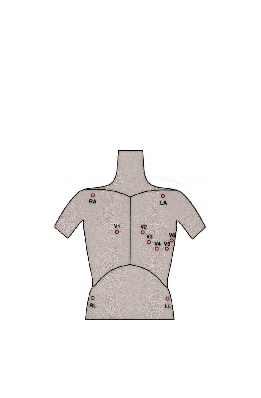
Attach the leads as shown in Figure 5, below (RA=right arm, LA=left arm, RL=right
leg, LL=left leg).
Figure 5: Electrode Placement
Resting ECG
NV-54/PCECG1200W
29
CHAPTER 7: RESTING ECG
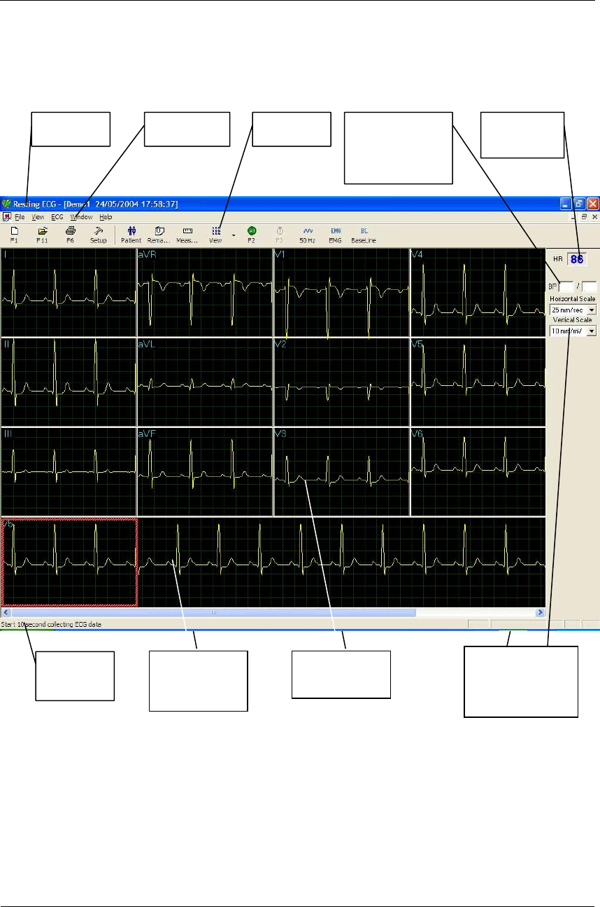
Figure 6: Resting ECG Main Screen
Program Menu bar Toolbar Blood pressure
systole/diastole
(user input)
Heart rate
(beats/min)
Timed
recording
Selected strip
display (strip
lead)
Multiple lead
display
Horizontal
(mm/sec) and
vertical
(
mm
/
m
V)
sca
l
e

Instructions for Use and Technical Description
Norav Medical Ltd.
30
Quick Start
To Perform a New Test
1. Click F1 (or the New button on the tool bar).
2. Insert patient details in the dialog box.
3. Click OK.
4. Enter blood pressure.
5. Click F2 to stop data collection or F3 to start data collection (10
seconds).
Operation with Function Keys
F1 New Recording
F2 Start/Stop
F3 10 sec. recording
F6 Print
F11 Open Saved Study
Table 6: Operation with Function Keys
For an example of a printed report, see Appendix C:, page 111.
Resting 12 Lead ECG
This application uses the standard 10 contact cables. It contains four limbs (RA, LA,
LL, and RL) and six chest (V1-V6) contacts. 12 derivations are recorded and
displayed:
• 3 Bipolar derivations: I, II, III
• 3 Augmented derivations: aVR, aVL, aVF
• 6 Unipolar derivations: V1-V6
• You can use a simpler cable with four contacts (only limbs). It produces
six derivations only: three Bipolar and three Augmented
Leads Placement
You can place the leads on the patient in various ways. The usual method is to place
the leads in the standard positions on the chest (V1-V6). To identify the placement of
Resting ECG
NV-54/PCECG1200W
31
the leads, the channels are renamed. Additional options for lead placement are V7-V9,
and the Right chest Lead system.
To Define the Lead System
1. Click Setup > Lead.
2. Select the lead system to use (Default: Standard).
Toolbar Overview
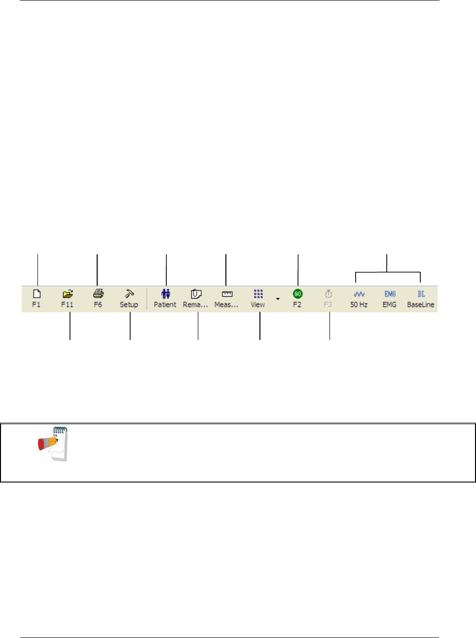
The Toolbar (Easy Toolbars Mode)
Figure 7: Resting ECG Toolbar
Note
The icons shown on page 35 are from the full toolbar. You can use the view menu to show an
abbreviated display with or without captions.
New Print Show patient
details
V
iew/modify
QRS values Start/stop Select
Filters
Open Set
preferences
Add
remarks
Select leads
to display
Record 10
seconds

Instructions for Use and Technical Description
Norav Medical Ltd.
32
Resting ECG Setup
Click Setup on the Toolbar to access the following parameters:
Tab Option Description
Leads Lead Systems
Define the lead system to be used and displayed according to the
electrode placement on the patient. Choose between Standard, Cabrera,
V7-V9, and V3R-V5R lead systems (default: standard system).
Default 3 leads Define the 3 leads that will be displayed as default when using 3x1-view
format.
Default 6 leads Define the 6 leads that will be displayed as default when using 6x1 or
3x2-view format.
Strip Lead 10 sec lead to appear in 4x3 and 6x2 formats.
ECG Recording Filter 50/60Hz
Default is cleared.
When checked, the default status of 50/60Hz filter is ON (according to
the checked frequency 50 or 60).
EMG Filter Default is cleared.
When checked, the default status of the EMG filter is ON.
Baseline Filter Default is cleared.
When checked, the default status of the Baseline filter is ON.
Save options
If Auto Save is ON, the file is stored by last name or by ID.
If Auto Save is OFF, a dialog box is displayed asking the user to enter a
file name.
Auto stop after
10 sec
If cleared (default), recording runs till stopped by the user.
If checked, stops recording automatically after 10 sec.
Auto Print
Use this option for automatic printing of the test at the end of the Rest
test. If more than one printer is defined in the network, select the
appropriate one from the list.
Simulator ECG
If cleared (default), ECG recording is done from the PC-ECG unit.
If checked, the ECG recording is done from the demo file included in
the software package. In this case, the recording unit is not needed.
Data Directory
Allows the user to define a directory for saved ECG recordings (if ECG
database is not used).
Use a secondary hard disk, if one is available.
Use ECG
Database
Select this option to connect to the default ECG database. When this
option is selected (checked) the ECG tests are saved in the database.

Resting ECG
NV-54/PCECG1200W
33
Tab Option Description
BACKUP Data
directory for
AutoSave mode
When Auto Save option is selected, this allows the user to define a local
path for a backup directory. The backup directory is useful when the data
directory or database is not on the same computer. In such a case, ECG
file save can fail due to failure in connection.
Diagnosis Optional. Active only if the measurement option (I1) is installed.
ST after J Defines the ST spot relative to the J point.
Print Options
Allows the user to determine if and when to have automatic results
printed. Define if measurements and/or interpretations should be added
to printouts. Options are Never, After Confirmation, or Always.
View Draw over lead
borders
If checked (default), does not limit the extreme high amplitude ECG
pulses from exceeding the borders.
If cleared, chops the pulses at the borders.
View calibration
pulse 1 mV
If cleared (default), the 1-mV pulse will appear only in printing.
If checked, the 1-mV pulse will also appear on the screen.
Leads Base line
shift
If cleared (default), the base line of each lead is exactly in the middle of
the lead’s area.
If checked, a special shift is added to each lead to view its maximum. For
example: lead V6, being positive pulsed, gets negative shift.
Separate Leads
If checked, leads are displayed framed and separated from each other.
If cleared, leads are not separated.
Default is checked.
Draw Grid
If checked, displays grid lines when the application is opened.
If cleared, the application is opened with no grid lines
Default is checked.
Horizontal Scale Sets the default value for the horizontal scale window on the screen
(mm/sec).
Vertical Scale Sets the default value for the vertical scale window on the screen
(mm/mV).
Rest ECG color
selection
Allows the user to choose colors for the Rest ECG application for
background, traces, grid, and text.
Restore Defaults When activated, restores the factory default colors: black for background,
yellow for traces, green for grid, turquoise for text.
Easy Toolbar
Mode
If checked, allows the user to use the regular Icons.
If cleared, allows the user to use the optional Icons
Text Label Adds text to the Icons.
Enables use by keyboard.

Instructions for Use and Technical Description
Norav Medical Ltd.
34
Tab Option Description
Installation Saves users’ data (hospital and physician). This data is printed on any
print out and sent as email.
Measurement
Standard
Define whether measurements will be calculated according to the metric
or the USA standard. Default is metric.
Magnetic Card
Reader
Select this option to use a magnetic card with bar-code to insert patient
details. (Select the magnetic card type.)
Environment Connection
Select the option button (COM port/USB), to choose the port the device
should be connected through.
If the COM port option is selected, select the serial input for the PC-
ECG unit from the COM port selection list.
If the USB connection is selected, the COM PC-ECG selection list is
disabled. (Default at installation is USB).
Display Size
Choose between 14/15-inch screen (default) and 17-inch screen. This
setting is required in order to display the ECG and grid in the correct
scale.
Graph paper
If set to On, prints 1mm and 5 mm squares on printouts.
Regular Grid is guaranteed to fit any printer.
Improved Grid shows a fine grid but may not work on some printers.
Paper Size Sets paper size. either conventional printer or 4-inch thermal printer.
Large Remarks
Font Enables large font for user entered free text.
Color Printout Select this option for colored printouts.
Shadow/Frame
For Area of
Interest
Allows the user to choose between shadow and frame to highlight the
interest area.
Picture Format AutoSave ECG
in Picture FormatSelect this option to save the test automatically as a JPG image.
Set File Name By Set the file names to include Patient Last Name or Patient ID. Check
date and/or hour to include them in the file name.
Picture Format Select the resolution of the picture (normal or high resolution).
Picture Directory Set the directory for saved pictures. The default is C:\Program
Files\PCECG\Data.
GDT/BDT Format Automatic Setup automatic GDT/BDT format.
Save test in
GDT/BDT If checked, save test automatically to GDT/BDT format.
Import from
GDT/BDT If checked, imports tests automatically as GDT/BDT format.
Resting ECG
NV-54/PCECG1200W
35
Tab Option Description
File Format Select the file format: GDT or BDT.
Import Codepage
437 Check this option to import Code page 437.
Export Codepage
437 Check this option to export Code page 437.
Edit Labels Click this button to open a dialog box with an editable list of the field
labels used in the GDT and BDT files.
GDT/BDT Data
Directory
Define the directory path where the GDT/BDT files should be
maintained.
Token for
PCECG Default is PEKG.
Token for
Practice EDP Default is EDV1.
Text File Auto Save Test
Data in Text file
Select this option to save the test data in a text file automatically at the
end of the rest test.
Set Text file
Name by
Set the text file name according to Test File Name or according to the
fields Patient ID and/or Patient Last Name.
Text File Data
Directory
Set the directory path to maintain the text files with the ECG data.
Default is C:\Program Files\PCECG\Data.
Table 7: Resting ECG Setup Options
Toolbar and Menus
To do this
Click
this
icon
Or use
this
short-
cut key
Or select this
menu Description
Start a new
study
F1 File > New
Rest Test
Starts a new 12 lead recording. The patient data can be
entered prior to ECG recording, but this is not
mandatory. The recording time is according to the setup
for ECG Recording: either continuous or limited to 10
sec. To stop recording, click GO/STOP.
Open an
existing study
F11 File > Open Shows recordings that are saved on disk.
Instructions for Use and Technical Description
Norav Medical Ltd.
36
To do this
Click
this
icon
Or use
this
short-
cut key
Or select this
menu Description
Import Data
from SCP Format
File > Import
from SCP
Format (Select
the required
file(s) and path
from the dialog
box and click
OK)
SCP format is a European format for ECG files. The
Rest application can identify these files, import them, and
save them as Rest files, either to the database or to the
defined folder for the Rest files.
Import
demographic
data from HIS to
PC-ECG
File >
GDT/BDT
Format
For details see
Import from
GDT/BDT,
page 105
This file always contains the last patient data.
Export the
GDT/BDT file
from PC-ECG to
HIS
File >
GDT/BDT
Format
For details see
Save Test in
GDT/BDT
page 105
This file always contains the last patient data.
Save a
recording
Ctrl+S File > Save Saves recording on disk (default file name: REST).
Send results via
email
File > Send
Sends recording data via email. If the large icons are used
the operation must be performed through the FILE
menu Prerequisites: e-mail software package, modem,
and internet provider (not included in the PC-ECG 1200
package).
Once an ECG study is displayed on the screen of the
transmitting side, click this icon to attach the ECG file
and send an e-mail to a specified address. The receiver
must have the PC-ECG 1200 software installed. A
regular email is sent with the ECG as an attached file.
The receiver can either double click the file to display the
ECG on the screen, or save it in the PC-ECG 1200
studies default directory.
Export to
MATLAB format
Ctrl+E
File > Export
to Matlab
Format
Saves ECG results in MATLAB format.
(For details see Using the Matlab Feature within PC-
ECG 1200, page 39).

Resting ECG
NV-54/PCECG1200W
37
To do this
Click
this
icon
Or use
this
short-
cut key
Or select this
menu Description
Create a text file
File > Create
Text File Saves ECG data in text format.
Save the test as
an image
File > Save
ECG to
Picture Format
Saves ECG test as a JPG image.
Print a miniature
printout of
results
File > Print
Average Mini
Card
Prints results as a mini-card that can be carried in the
pocket or wallet.
Print results
F6 File > Print Prints the recordings currently shown on the screen.
Note that the 1-mV signal is always printed.
Set preferences
View > Setup
Allows the user to set preferences for Leads, ECG
Recording, Diagnosis, View, Installation, Environment,
Picture Format, GDT/BDT Format, and Text File.
For details see Table 7, page 35.
Display
program,
hardware, and
contact
information
Help > About
Displays software version number (which should be
quoted on any software inquiry) software key, and
permissions; Norav contact information; memory size
and free disk space; HASP ID number (ID of existing
software keys). This ID number is used for adding
software options.
Print patient
data
— View > Patient
Data
Can be added to the recording. It will be printed together
with ECG traces.
If the recording is saved, then the PATIENT DATA will
be saved together with the ECG traces. Use the Previous
option if the same patient undergoes a second study.
Add remarks
—
View >
Remarks\
Interpretation
Allows the user to enter free text during or after the
ECG recording. This is printed and saved together with
ECG traces. If the Interpretation option is installed, then
Interpretation Statements is also displayed.

Instructions for Use and Technical Description
Norav Medical Ltd.
38
To do this
Click
this
icon
Or use
this
short-
cut key
Or select this
menu Description
View and
modify QRS
values
—
View >
Measurements
An optional feature that requires a software key (I1 or I2
license).
Displays a comprehensive table of measured values. You
can alter the values either by editing them in the table or
by using Caliper to change the horizontal and vertical
markers. When Caliper is activated, a large QRS is shown
with the standard markers. Open the Standard Markers
window (upper right side) and select the QRS interval of
interest for modification. The area changes to blue. Use
the mouse to move the markers.
(For details see Measurements/ Interpretation, page
85).
Display/hide
the grid
— View > Grid Displays or hides the 5mm raster grid. Print outs are
always with 1mm raster.
Display
information from
different leads (5
options)
Display 3x4
—
View > Leads
Format > 3x4
Windows
Classical format. 12 lead ECG of 2.5sec ECG + 10sec
trace.
*
Display 6x2
—
View > Leads
Format > 6x2
Windows
12 lead ECG of 5sec ECG + 10sec trace.
*
Display 12x1
—
View > Leads
Format > 12
Leads
12 lead ECG of 10sec ECG.
*
Display 6x1
—
View > Leads
Format > 6
Leads
6 lead ECG of 10sec ECG.
*
Display 3x1
—
View > Leads
Format > 3
Leads
3 lead ECG of 10sec ECG.
*
View/print
averages
—
Produces a typical QRS for every lead from the raw ECG
data. The averages can be printed either full size or
minimized in a credit card size.
To perform a miniature print, enter FILE and then
PRINT MINIATURE.