Norsat 5200-KUAA-ID GLOBETREKKER KU-BAND SATELLITE TERMINAL User Manual GT Manual Rev 2 FCC
Norsat International Inc. GLOBETREKKER KU-BAND SATELLITE TERMINAL GT Manual Rev 2 FCC
UserManual.wiki
>
Norsat
>
5200-KUAA-ID User Manual
>
USERS MANUAL 6 OF 8
Contents
1.
USERS GUIDE
2.
USERS MANUAL 1 OF 8
3.
USERS MANUAL 2 OF 8
4.
USERS MANUAL 3 OF 8
5.
USERS MANUAL 4 OF 8
6.
USERS MANUAL 5 OF 8
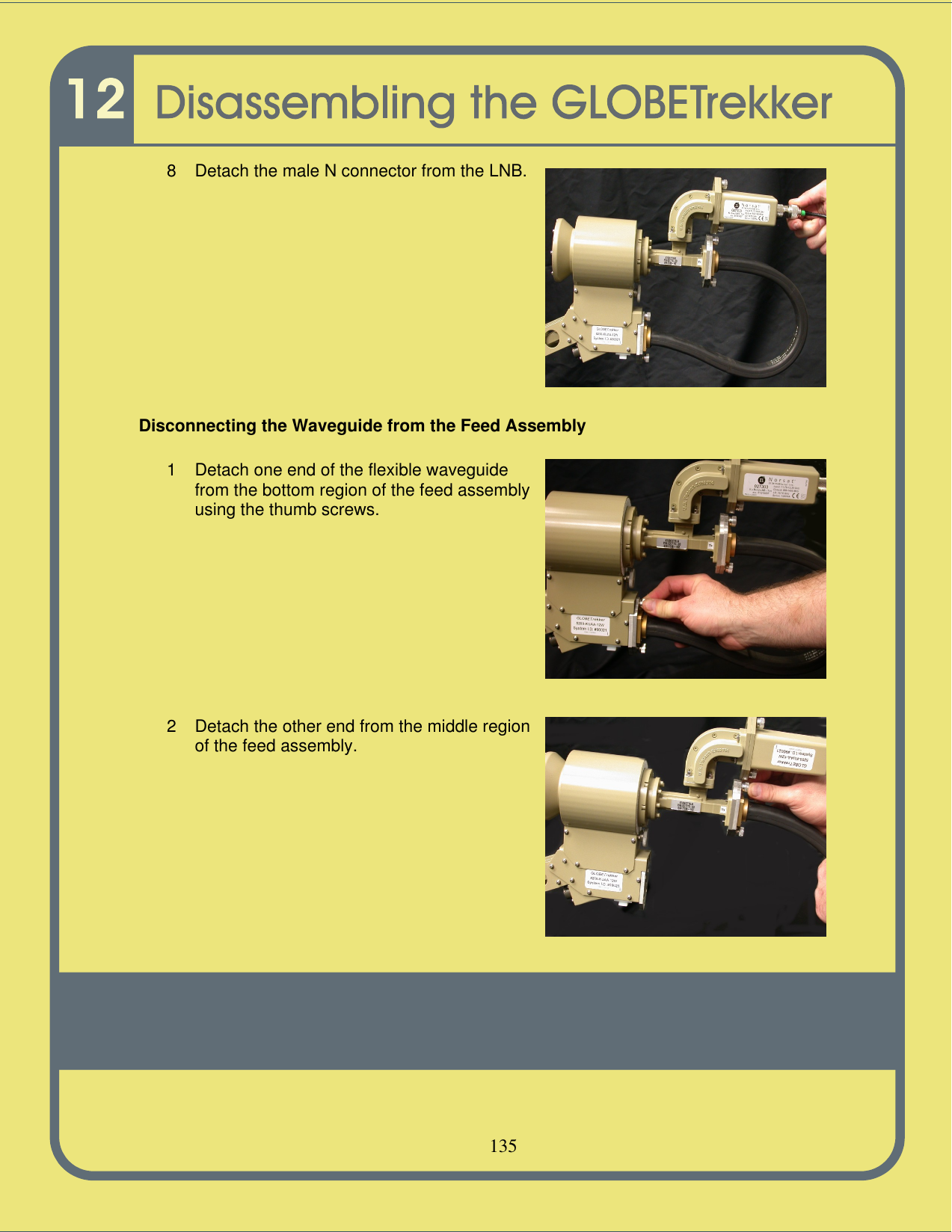
7.
USERS MANUAL 6 OF 8
8.
USERS MANUAL 7 OF 8
9.
USERS MANUAL 8 OF 8
USERS MANUAL 6 OF 8
Navigation menu
Upload a User Manual
Namespaces
Wiki Guide
HTML
PDF
Info
Views
User Manual
Discussion / Help
Navigation