Norsat 5200-KUAA-ID GLOBETREKKER KU-BAND SATELLITE TERMINAL User Manual GT Manual Rev 2 FCC
Norsat International Inc. GLOBETREKKER KU-BAND SATELLITE TERMINAL GT Manual Rev 2 FCC
Norsat >
Contents
USERS MANUAL 6 OF 8

111
Sample Script
for
Telephone Conversation
with
a Hub or Satellite O
perator
(Manual operation)
User to SO:
Hello, my name is __ and I’m calling from __. My number is __.
I am r
eady to start transmitting on
satellite
NSS7, Transponder
K1
8,
Slot C
at 14114MHz.
SO to User:
OK, please bring up a clean carrier
User Action:
Turn on Clean Carrier at low power
User Action:
Press
CW Minimum Quick Key
SO to User:
OK we see that, please increase power
SO to User:
Increase carrier to nominal
U
ser Action:
Press CW Nominal Quick Key.
User to SO:
Increasing power. It will take a few seconds
User to SO:
We are at nominal power
SO to User:
Looks good. Go ahead and modulate
User Action:
Turn on modulation
User Action:
Press Modulated Nominal
Quick Key

112
This page left intentionally blank.

113
Operating the GLOBETrekker™ in Manual Mode
Manual Antenna Alignment Overview
......................................................................
114
Ground Location
.......................................................................................................
118
Adjusting the Azimuth
...............................................................................................
121
Adjusting Antenna Elevation
....................................................................................
121
Setting Antenna Polarization
....................................................................................
121
Aligning the Antenna
................................................................................................
121
Viewing the Receiver Spectrum Analyzer Screen
....................................................
122
Peaking the Antenna
................................................................................................
128

114
Th
is chapter enables a user to manually align the antenna towards the desired satellite;
peak on the satellite; and verify that they are on the correct satellite. This chapter also
takes users through a satellite access procedure.
Manual A
ntenna Alignment Overview
There are eight steps in the manual operation:
1.
Launch LinkControl Application and Choose a Profile
2.
Identify Location
3.
Verify Target Satellite
4.
Check Clearance Distance
5.
Check if
there is a DVB Carrier on the target Satellite
6.
Point the Antenna
7.
Acquire Satellite and Peak Antenna
8.
Call Hub (or Satellite) Operator to Access Satellite
Step 1a:
Launch Link Control Application
Th
e LinkControl application will launch automatically
once
the GLOBETrekker has been
powered up.
Access to the LinkControl application screen will be available after t
he laptop has been
connected to the GLOBETrekker
baseband unit a
nd the
laptop has been powered up.
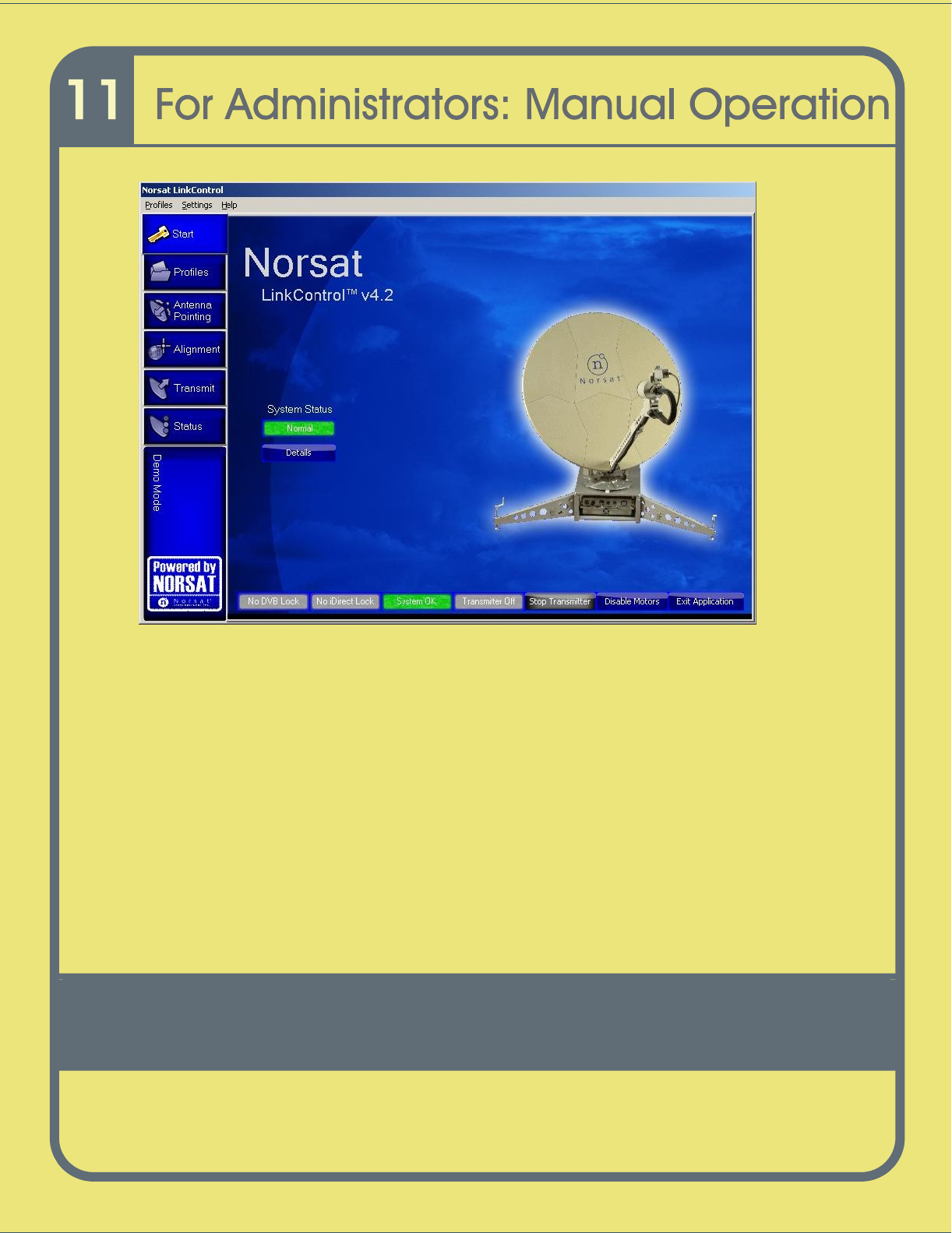
It may take several minutes for the applicatio
n to appear on the screen. The application
will open with the Startup screen being displayed as in
Figure 3
6
.
The LinkControl application performs numerous diagnostics upon start
-
up.
The operator should allow the LinkControl application to fully comple
te its diagnostics
before attempting to take control of the application.
The results of the diagnostics can be
viewed by pressing the DETAILS button below the System Status indicator.
115
Figure
34
Startup Screen
T
his process is p
assword
-
protected and is accessible only to users designated as
"administrator(s)" in LinkControl
.
If you are using the GLOBETrekker for the first time, the system will come with an
Administrator password. This can be changed at a later date.
To enter Ad
ministrator mode:
1
On the Menu bar press Settings
-
> Enter Admin Mode
2
Enter the Administrator password. By default the password is “Administrator”.
Note: Passwords are case sensitive
To exit Administrator mode and enter Operator mode:
1
On the Menu bar pres
s Settings
2
Select Exit Admin Mode
116
Step
1b:
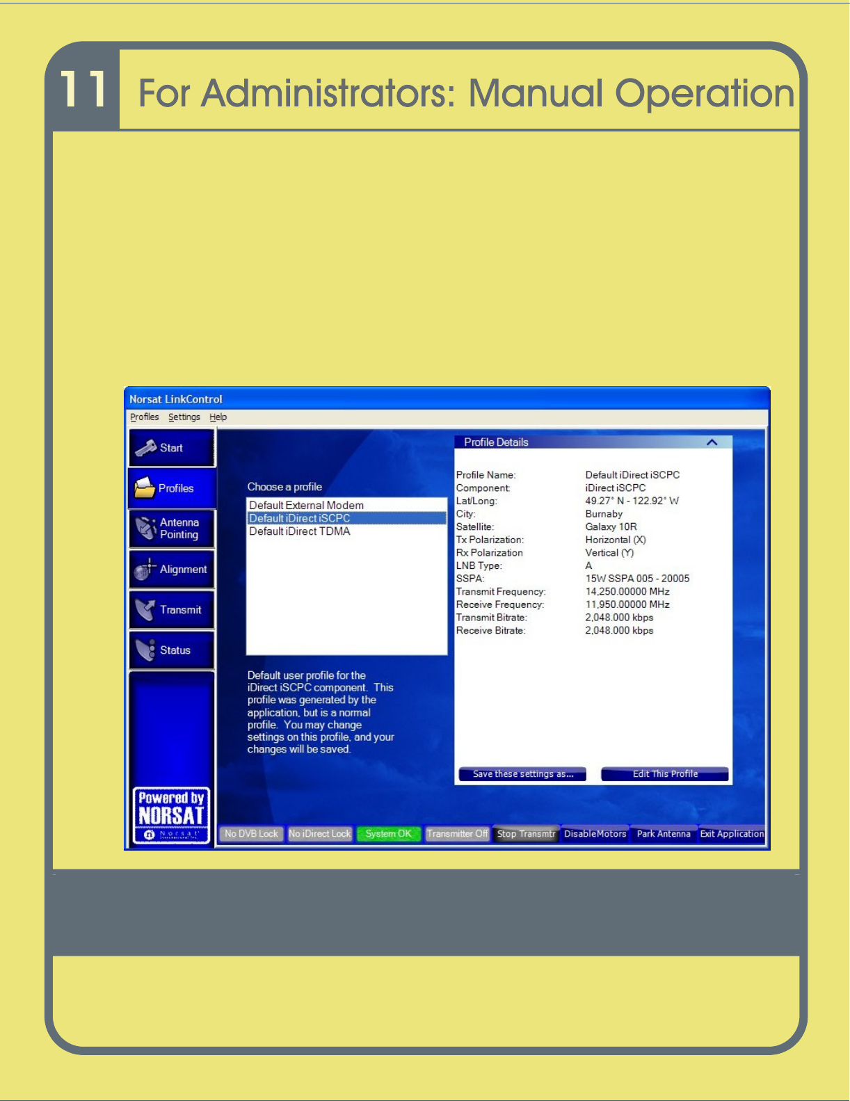
Choose a Profile
Choose an
E
xisting
P
rofile:
a
Click on the Profiles tab on the left side of the screen; refer to
Figure 3
7.
b
Click on
a
profile in the list of profiles under
Choose a profile.
c
A summary of
the selected profile is displayed on the right side of the screen.
Figure
35
Choose a Profile
117
Step
2:
Identify Location
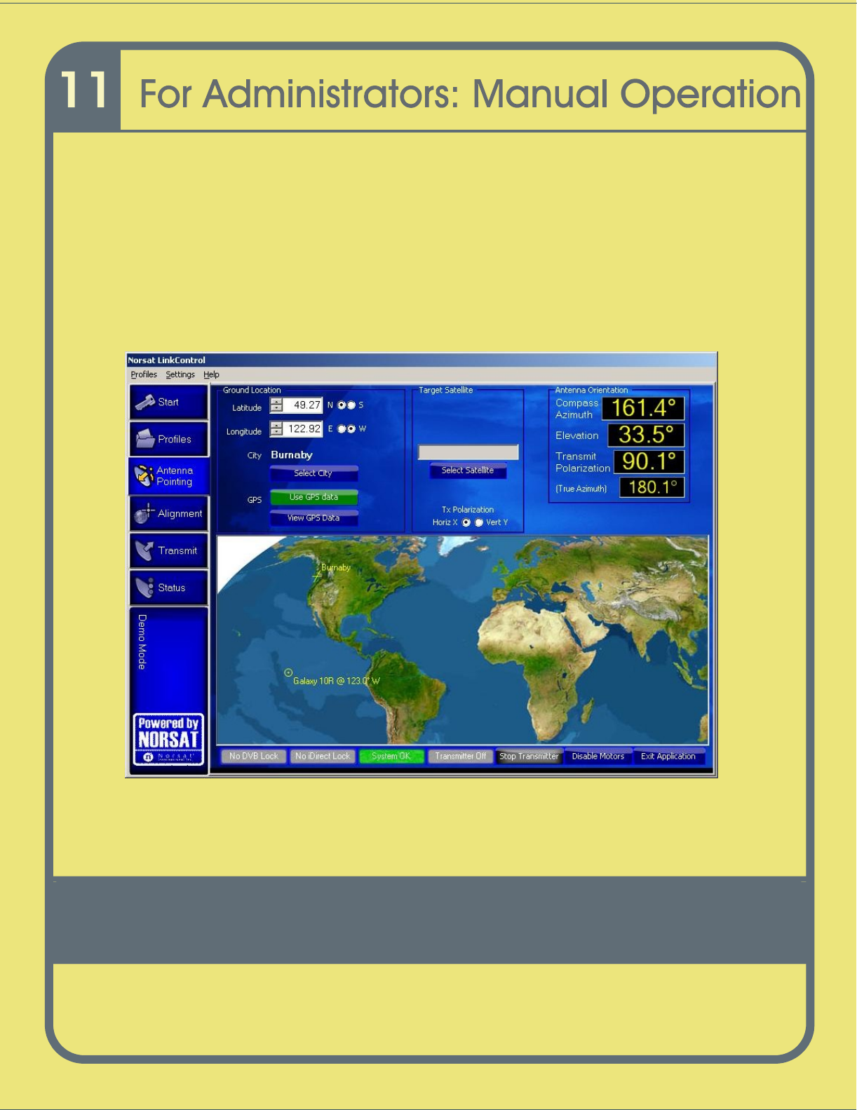
To point the antenna to a satellite, complete the following steps.
1
Click
Antenna Pointing
on the Toolba
r. The
Antenna Pointing Screen
opens
as shown in
Figure
38.
The
Antenna Orientation
fields display the antenna
pointing
values.
Figure
36
Antenna Pointing Screen
The world map in
Figure
38
shows the
GLOBETrekker
position and t
he position of the
selected satellite.

118
Ground Location
The LinkControl application must know your current ground location in order to calculate
the look angles required to point the antenna at the satellite.
The l
ocation of the terminal can be determined in three different ways:
i)
manually entering the latitude and longitude
ii)
selecting your location from the City list
iii)
or by using the supplied GPS receiver.
If the selected profile does not already have the GLOBETrekker’s current location, use
the following steps:
To select location from the city list
1
Click on
Select City
2
Expand the continent and country trees by clicking on the
+
sign.
3
Click on the nearest city.
4
Click
OK.
To determine location using the GPS:
1
Ens
ure the GPS is connected. If this was not done during the set up, the GPS
will not be initialized.
To initialized the GPS:
a
Click on
View GPS Data
b
Click on
Initialize
c
Click on
Close
2
If the
Use GPS Data
button is green, it has acquired a location. Press t
he button
to use the GPS information as its position.
Note: The GPS unit requires a clear and unobstructed view of the sky to operate
properly. If portions of the sky are blocked, it may impact acquisition time.

119
To manually enter latitude and longitude:
1
Enter the Latitude in the box or select the value using the scroll arrows.
2
Select the North or South radio button.
3
Enter the Longitude in the box or select the value using the scroll arrows.
4
Select the East or West radio button.
Note: The format
for latitude and longitude is <Degrees.Decimal Degrees>
Step 3:
Verify Target Satellite
Confirm the satellite name that appears in the white
Target Satellite
box on the Select
Satellite
drop down screen.
Step 4
:
Check Clearance Distance
1
Click on the Al
ignment
tab.
2
On the
Alignment
screen
, click the
Clearance Distance
tab.
3
Ensure that there are no obstructions within the clearance range listed.
For more information on clearance distances refer to Chapter 1
–
Safety Basics.
Step 5:
Check if there is a
DVB Receiver on the Target Satellite
1
Click the DVB Receiver Lock tab on the left side menu.
2
Check to see if a DVB carrier appears in the box
in the upper right corner as
shown
in
Figure
39
.
3
Select a DVB carrier if one is present (DVB listed to the right
of the
Current Rx
Polarization:
section as shown in
Figure 3
9
).
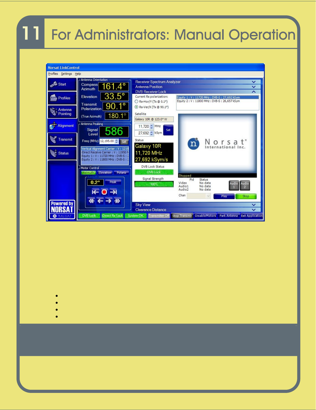
120
Figure
37
DVB Receiver Lock
If no DVB carriers appear in the box, you will need to rely on the presence of either a
beacon or modem carrier
(
Step
7 in the fol
lowing pages) when acquiring the satellite
signal.
Ste
p 6:
Point the Antenna
Once the Norsat LinkControl application has its location and desired satellite, it will
automatically calculate the look angles required to point the antenna at the satellite.
T
he application calculates four values:
Compass Azimuth
–
magnetic compass bearing to which the antenna should be set
Elevation
–
angle to which the inclinometer should be set
Polarization
–
angle to which the feed should be rotated
True Azimuth
–
bearing
relative to Geographic North rather than Magnetic North
121
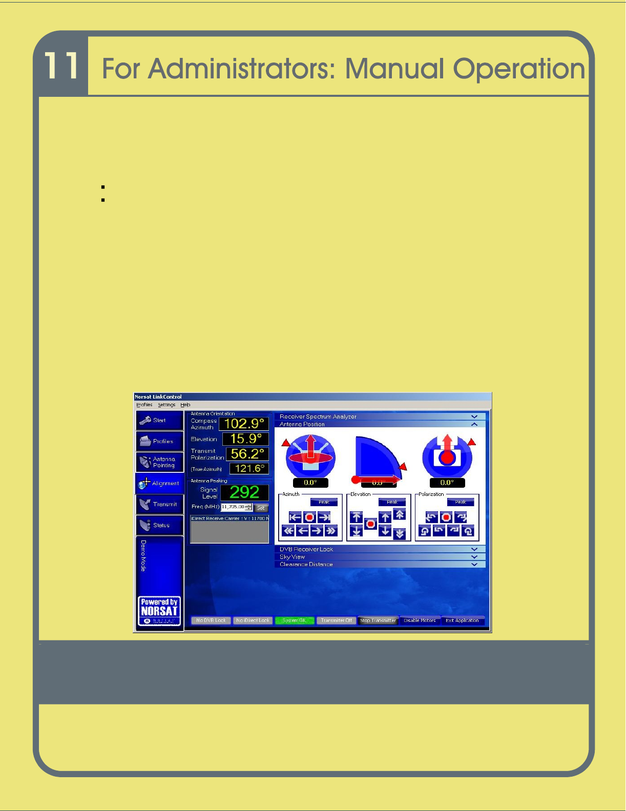
Aligning the Antenna
To align the antenna, click
Alignment
on the
GLOBETrekker
Functions Toolbar
on the
left side menu
. The
Alignment
s
creen
opens.
Adjustin
g the Azimuth
Click on Antenna Position sub screen.
Adjust the azimuth plate on the baseband unit until the compass bearing matches
the
degrees shown in the
Compass Azimuth
field
(
as shown in
Figure
40
)
, using
the
arrows inside the Azimuth positioning box
.
Adjusting Antenna Elevation
To
adjust the antenna elevation,
a
djust the elevation of the antenna to match the
degrees
as shown in the
Elevation
field
(as shown
in
Fi
gure
40
) using the
arrows inside
the Elevation positioning box
.
Setting Antenna Polarization
Set the Tx polarization to match the value set in the Transmit Polarization
field
(
as
shown in
Figure
40
)
using th
e arrows inside the Polarization positioning box
.
Figure
38
Antenna Pointing Screen

122
Step 7:
Acquire Satellite and Peak Antenna
Acquiring the satellite and peaking the antenna involves the use of the built
-
in spectrum
analyz
er, a DVB lock indicator, and a modem lock indicator.
The process of acquiring a satellite and peaking the antenna is easiest when a satellite
has a DVB carrier and a beacon. Where a DVB carrier does not exist a beacon can still
be used.
Note: When nei
ther a DVB carrier nor a beacon exists, other types of carriers, if
present, and/or reference satellites can still be used to acquire a particular
satellite. This chapter does not address such occurrence. To learn more about
how to handle such situations,
attend a Norsat training session.
The reference level (dBm) and the dB per division functions will be set to auto mode
(these are pre
-
selected and set from the factory).
Note: Advanced users can deselect either or both the reference level and the dB
pe
r division in order to configure the spectrum analyzer to settings of their choice.
Additionally, the Center Frequency and Frequency Span are also adjustable
using scroll arrows.
The process of acquiring a satellite and peaking the antenna requires the us
e of the
Spectrum Analyzer Screen.
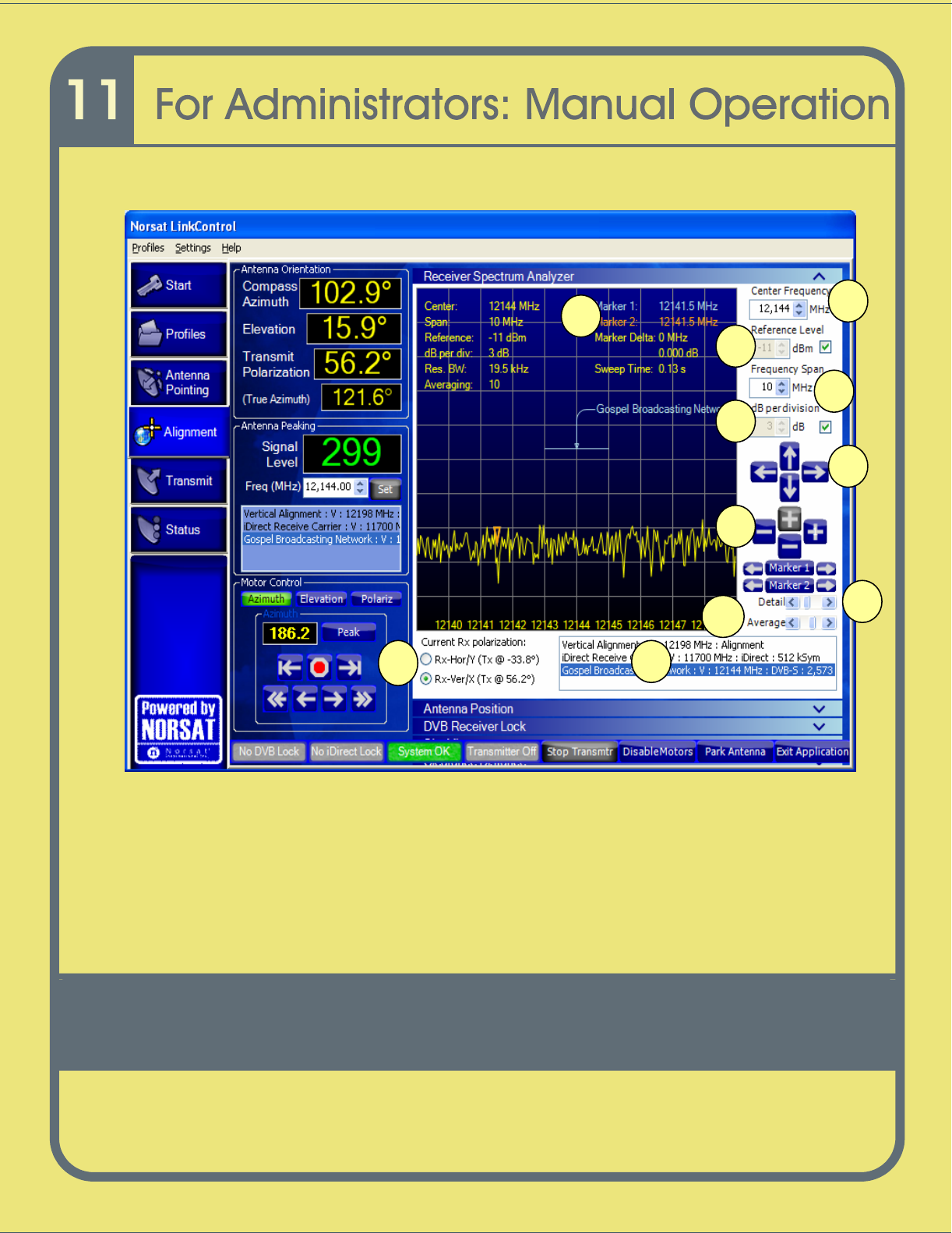
Viewing
the Receive (Rx)
Spectrum Analyzer Screen
To open the Receiver Spectrum Analyzer Screen, click the down arrow beside the
Spectrum Analyze
r. The
R
eceive Spectrum Analyzer Screen
opens as shown in
Figure
41.
The
Receive Spectrum Analyzer
screen
,
shown in Figure 41
displays physical
parameters along the X axis and the Y axis as follows:
frequency along the X axis
signal amplitude along the Y axis
123
10
1
1
9
2
1
3
4
5
6
7
8
Figure
39
Alignment Screen with Rx Spectrum Analyzer
124
Table
5
lists the controls and the functions for the
Receive Spectrum
Analyze
r.
Refer to
Figure
41
for locations of the functions on the screen.
Table
5
Controls on the Rx Spectrum Analyzer
Controls
Functions
Rx Spectrum Analyzer
1.
Center frequency (MHz)
To change the
Center
frequency, complete the
following steps:
1
Click the up/down arrows to increase or decrease the
frequency OR
2
Type in t
he desired frequency OR
3
Use the horizontal arrows to adjust the frequency.
4
Set a marker to the desired frequency.
5
Click on either Marker 1 or Marker 2 depending on
the pre
-
selected frequency setting.
Note: see number 5 in table for more detail.
2.
Re
fere
nce level (dBm)
To adjust the
Reference
level
field
, complete the following steps:
1
Click the up arrow to increase the reference
level by 5dB
.
This moves the trace down the
screen.
2
Click the down arrow to decrease the
reference level by
5dB. This moves the
trace up
the screen.
Hint: the check box to the right of the Reference Level settings
should be unchecked (deselected) to make manual changes to
the reference level settings and checked (selected) when the
system is operating.
Note: see number 5 in table f
or more detail.
3.
F
requency Span (MHz)
To adjust the
Span
frequency, use the
+ /
-
buttons and complete
the following steps:
1
Click the right
+
button to decrease
Span
frequency.
2
Click the left
-
button to increase the
Span
frequency.
Note: see number 6 in
table for more detail.
125
Table
5
Controls on the Rx Spectrum Analyzer
-
continued
Controls
Functions
Rx Spectrum Analyzer
4.
d
B per division
To adjust the
dB per div
, use the
+ /
-
buttons
and complete the
following steps.
1
Click the upper
+
but
ton to decrease the
dB
per div
by
1dB.
2
Click the lower
-
button to increase the
dB
per div
by 1dB.
3
Range is 3 to 10dB per division in steps of 1 dB.
Hint: the check box to the right of the Reference Level settings
should be unchecked (deselected) to make m
anual changes to
the reference level settings and checked (selected) when the
system is operating.
Note: see number 6 in table for more detail.
5.
Frequency Adjust and
Reference Adjust
Frequency adjustment controls (center frequency):
Are the Left and Rig
ht arrow buttons.
Left arrow for DOWN frequency adjust and Right arrow for
UP frequency adjust.
Reference adjustment controls (reference level):
Up and Down arrow buttons.
Up arrow for UP reference adjust and Down arrow for
DOWN reference adjust.
6.
Frequ
ency Span and
Strength Span Adjust
Frequency Span adjustment controls (frequency span):
Are the Left and Right Minus/Plus signs.
Left side Minus Increases frequency span and Right side
Plus sign Decreases frequency span.
Strength Span adjustment controls (dB per division):
Are the Top and Bottom Plus/Minus signs.
Top Plus sign Decreases strength span and Bottom Minus
sign Increases strength span.
126
Table
5
Controls on the Rx Spectrum Analyzer
-
continued
Controls
Functions
Rx Spectrum Analyzer
7.
Detail
Detail controls the number of sweep samples used in drawing the
signal trace in the Spectrum Analyzer.
Increasing the sweep detail increases the amount of
time required
to
draw the trace on the spectrum
analyzer. It is normal to leave
this set t
o high detail as it
may be difficult to distinguish signals
when the detail is
set to
o
low.
Detail changes the resolution bandwidth of the Spectrum
Analyzer. The following resolution bandwidths are available:
600Hz, 1.2KHz, 2.4KHz, 4.9KHz, 9.8KHz, 19.5KHz
and
39.1KHz
8.
Signal Averaging
Controls the number of sweep samples averaged and
displayed
as one trace; Averaging ranges from 1 (no
averaging) to 16.
9.
Rx and Tx polarization
Rx polarization rad
io buttons control the types of
carriers which
appear in
the carrier selection list
(see #10 in
Figure 41
or this
table)
.
This
enables a user to check for a known signal on the
opposite
polarization to help verify the correct satellite.
To view alternate polarization signals, complete the
following
steps:
1
Click
the radio button to select the type of
polarization.
2
Adjust the polarization settings on the feed
assembly.
3
Return to the desired polarization type before Tx.
10.
C
arrier selection list
The carrier selection
list enables a user to set the sp
ectrum
analyze
r to view a particular signal.
Clicking
on a carrier in the list automatically sets the
Center
frequency and
Span
to match the
selected carrier.
127
The acquisition process involves:
1
Choosing a DVB
-
S carrier or Beacon carrier from the list a
s shown in
Figure
41,
box 10.
2
Sweeping for a Signal.
a
Click on the Azimuth button in the Motor Control box, as shown in
Figure
41
.
b
Use the arrows until a signal appears in your main screen as shown in
Figure
41
(if no signal appears or is visible, use diff
erent carrier or change Span).
3
Verifying the satellite. Perform the following for each of the carriers that appear in
Figure
41
, box 10.
a
Select the carrier, either DVB carrier or Beacon carrier.
b
Look at the Receive Spectrum Analyzer screen and if the be
acon carrier is
chosen, ensure that spike appears in middle of the screen. If DVB carrier is
chosen, ensure that signal is in the center of the screen and that
l
ist
bandwidth is close in width to the horizontal line (indicator) displayed on the
screen. In
Figure
41
, indicator is for the Gospel Broadcasting network DVB
carrier.
You are now pointing at the satellite and need to peak the antenna to maximize your
signal strength.
Table
5
Controls on the Rx Spectrum Analyzer
-
continued
Controls
Functions
Rx Spectrum Analyzer
1
1.
Marker Functions (MHz)
measure
s
the amplitude
difference (marker delta); the
bandwidth of signals
and
change
s
the
Center
frequency
To set a marker, complete the following steps:
1
On the Spectrum Analyzer, move the pointer to t
he
spot
you wish to mark
.
2
To set Marker 1,
left click
with mouse,
Marker
1 is
displayed as a blue arrow.
3
To set Marker 2,
right click
with mouse,
Marker 2 is
displayed as an orange arrow.

128
The peaking process involves:
1
Setting DVB Carrier
2
Sweeping the Azimuth
3
Conf
irming DVB and Modem Lock
Peaking t
he Antenna
To peak the
antenna, complete the following steps:
1
Choose a
DVB
-
S
carrier. To select the carrier, click on a carrier in the list
shown
on
Figure 41
, box 10.
2
Reset the
frequency span to 10 MHz (if the frequency span is currently set at a
level higher than 10 MHz). The reading on the signal level indicator in the
Antenna Peaking box (
Figure
41
) should be green.
Hint: If the signal strength indicator is red it cannot be u
sed for peaking, reset
your frequency span until it turns green.
3
Use the nudge left/right arrows to adjust the Azimuth such that the reading on the
signal level indicator is the highest that can be achieved. This number will vary
depending upon the satell
ite.
4
Click on Elevation button in the Motor Control Box to activate this control. Use
the nudge left/right arrows to adjust Elevation such that the reading on the signal
level indicator reaches the highest number that can be achieved.
5
Once the highest s
ignal level has been achieved, peaking is complete.
6
Verify that you have a DVB Lock and iDirect Modem Lock.
7
You are now ready to call the Hub operator to gain access to the satellite.
129
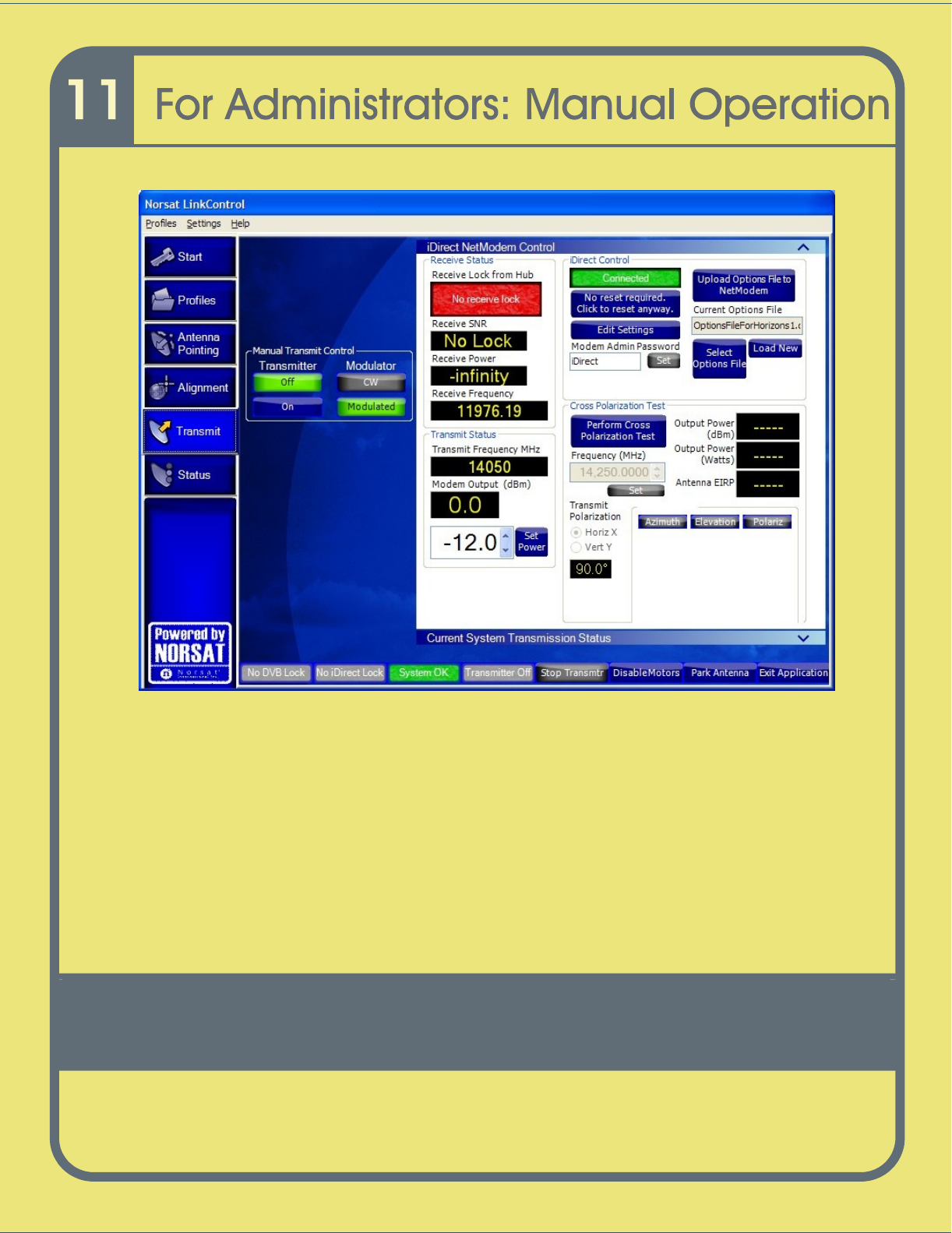
Step 8:
Call Network Operator to Access Satellite.
1
Go to the
Tran
smit
tab and click the iDirect NetModem control.
2
The user should
call the Network/Satellite Operator to
:
i.
Identify themselves and their location (leave your phone number)
ii.
Indicate that they have scheduled satellite time (leave time, freq.)
iii.
Indicate purpose
of the transmission (example: data transfer)
iv.
Indicate that you are ready to start transmitting on satellite, transponder and
frequency slot allocation (example: NSS7, Transponder K18, Slot C)
The satellite operator may in turn verify some parameters and
ask some
questions.
Such parameters/ questions may include:
Are you aligned and peaked on the satellite?
Modem settings
.
Confirm Uplink frequency and polarization
.
3
When directed by the hub/satellite operator to start transmitting at low power,
unmodulat
ed carrier (also known as a CW or continuous wave) , click on the
Perform Cross Polarization button in the Cross Polarization test box (refer to
Figure
42
). The transmitter will now be
On
and modulator
CW
button will turn green.
4
Wait for further instructi
ons while the operator checks the cross pol and frequency
of the carrier. The operator may instruct you to adjust the transmit power,
frequency, polarization, and / or antenna pointing.
130
Figure
40
iDirect NetModem Controls Scree
n
5
When directed, slowly increase power to operating level and stop.
6
Wait for further instructions while carrier specifications are checked.
7
When directed, modulate the signal and verify the downlink (adjust power if in
SCPC mode).
8
Wait for further inst
ructions while your carrier and bandwidth is checked
The controller will verify your phone number and the end time for your uplink. The
controller will remind you to call the NOC again just before the end of the uplink
(Goodnight call).

131
Disassembling the GLOBETrekker
Disconnecting the
Laptop
Unit
.................................................................................
132
Disconnecting the Power Supply
..............................................................................
132
Disconnecting the Cables
.........................................................................................
133
Disconnecting t
he Waveguide from the Feed Assembly
.........................................
135
Detaching the LNB from the Feed Assembly
...........................................................
136
Disassembling the Boom Arm and Feed Assembly
.................................................
137
Disassembling the Main Antenna U
nit
.....................................................................
138
Folding the Legs and Leg Supports
.........................................................................
141
Repackaging the GLOBETrekker Antenna/RF Backpack
........................................
143
Repackaging the GLOBETrekker Baseband Backpack
...........................................
147
132
The chapter explains how to disassemble the GLOBETrekker through step by step
instructions.
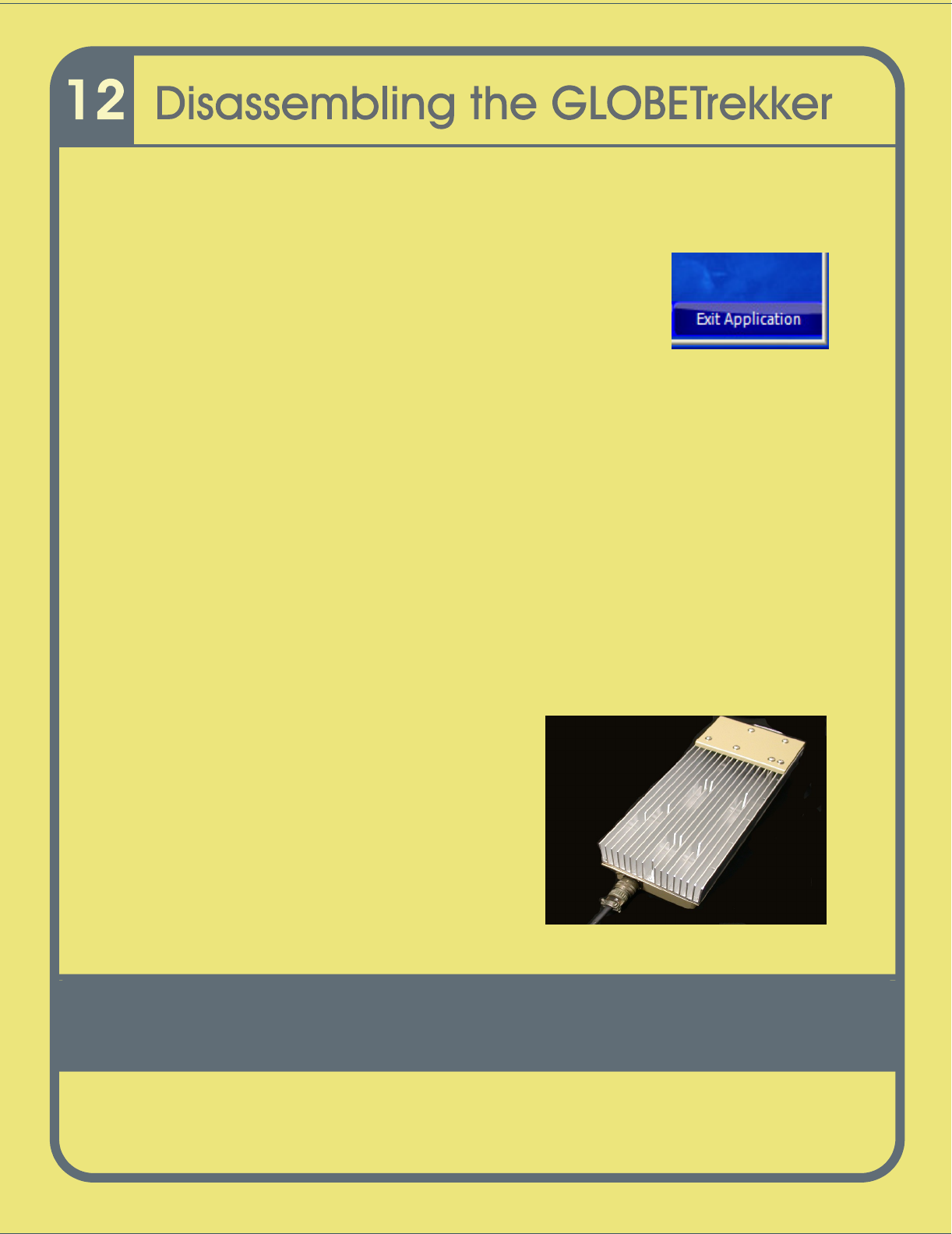
Powering Down the GLOBETrekker
(Graceful Shutdown)
1
To power
down
the GLOBETrekker properly, first exit the
LinkControl application by clicking o
n the
Exit Application
button located on the bottom right
-
hand side of the
LinkControl screen
.
2
Next, shutdown
the Windows XP application and
the
n turn
the power to laptop the
OFF.
Disconnecting t
he
Laptop
1
Turn the power off to the
laptop
.
2
Disconnect the
laptop control
unit from the
baseband unit.
Disconnecting t
he Power Supply
To detach the cables from the power
supply, perform the following steps:
1
Detach the AC cable from the power
source.
2
Detach the AC cable from the three
pin
mal
e connector on the power supply.
3
Detach one end of the DC cable from
the
baseband unit front panel.
4
Detach the other end of the DC cable
from
the four pin female con
nector on
t
he power
supply.
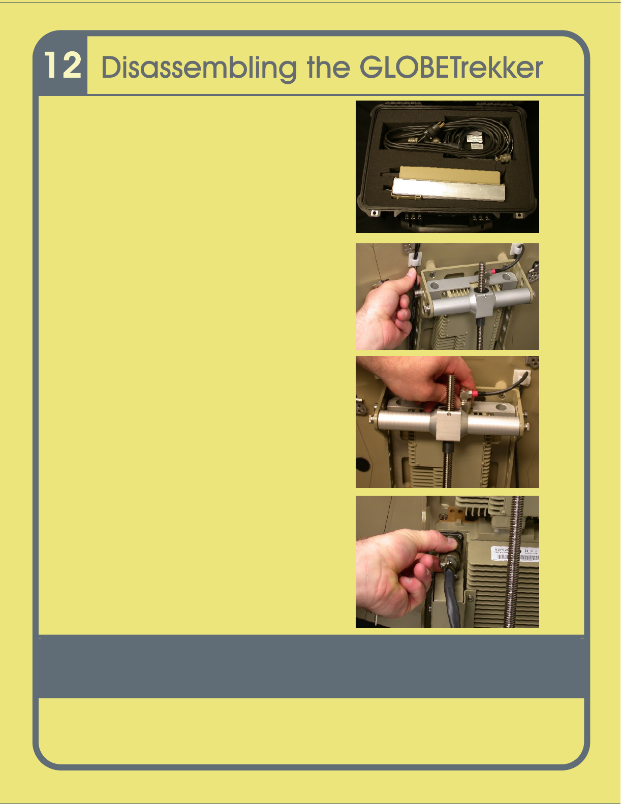
133
Repackage
the
power supply into the options case
as shown
.
Disconnecting t
he Cables
1
Unclip the
cables from the boom arm and
the back of the antenna.
2
Detach the
9
0°
male N connector (
color
coded
red
) from the top of the BUC.
3
Detach the 12 pin female amphenol
connector from the SSPA.
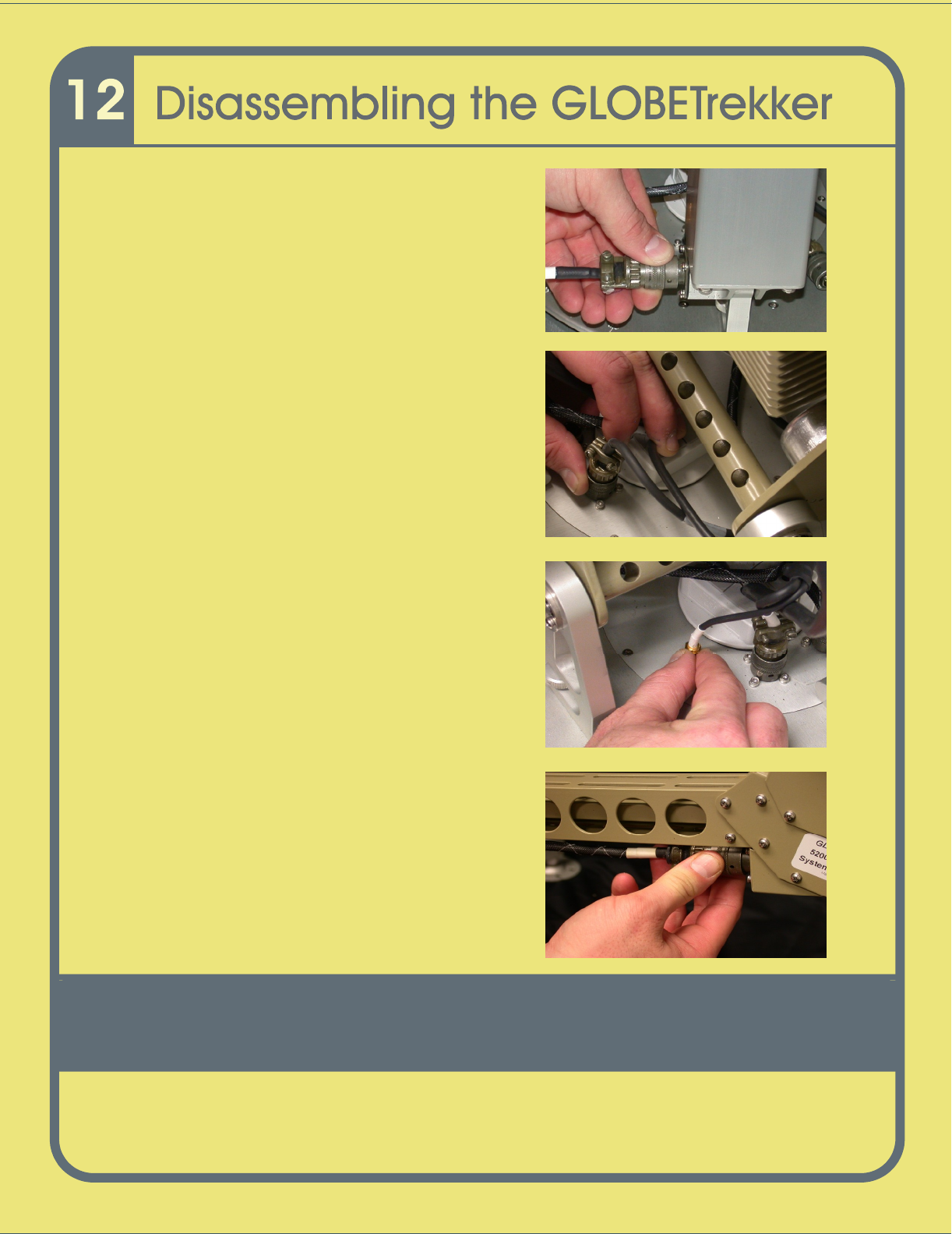
134
4
Detach the 6 pin female amphenol
connector from the elevation assembly.
5
Detach the 3 pin male amphenol
connector
from the baseband unit.
6
Detach the 4 pin male amph
e
nol connector
and the Subminiature A (SMA) connector
from the baseband (GPS antenna and
Compass cable).
7
Detach the 8 pin amphenol connector from
the base of the feed assembly.

135
8
Detach the male N connector from the LNB.
Disconnecting the Waveguide from t
he Feed Assembly
1
Detach one end of the flexible waveguide
from the
bottom region of t
he feed assembly
using the thumb
screws.
2
Detach the other end from the middle region
of the
feed assembly.