Norsat 5200-KUAA-ID GLOBETREKKER KU-BAND SATELLITE TERMINAL User Manual GT Manual Rev 2 FCC
Norsat International Inc. GLOBETREKKER KU-BAND SATELLITE TERMINAL GT Manual Rev 2 FCC
Norsat >
Contents
USERS MANUAL 5 OF 8

76
This is a very critical chapter as it identifies the steps necessary to
commission the
GLOBETrekker
and
bring it into operation within
an iDirect TDMA network
(TDMA mode)
or
on a
iDirect (or Paradise)
SCPC
network (
SCPC
mode
).
The commissioning process
ensure
s
operation of the GLOBETrekker following:
(i)
r
eceipt
of the GLOBETrekker from the factory
(ii)
c
hange
in satellite
or
transponder to be used
(iii)
c
hange
in hub
(or network operator)
–
TDMA only
(i
v)
c
hange
in locations
LinkControl Overview
:
A
Norsat proprietary
software application
called
LinkControl
controls the GLOBETrekker.
You will use LinkControl to commission the GLOBETrekker.
The LinkControl ap
plication interfaces with the built
-
in modem (router); enables users to
point the antenna towards the desired satellite, peak on the satellite and save user
settings; and access the “alarm console” in the LinkControl System Status screen.
Unlike many
other systems, the modem (or router) is housed inside the baseband
enclosure. This has been designed to minimize the weight and enhance portability of
the GLOBETrekker terminal. The firmware software supplied by iDirect
(or Paradise)
is
embedded on the modem board.
NOTE
for iDirect Users:
Your network must be at
iDS version 6.0.7
or later to support the built
-
in iDirect
iConnex iNFINITI modem. Please
verify the firmware version that has been loaded
for your
iDirect iConnex iNFINITI modem.
Note:
Those users who are familiar with iDirect iSite ® software will recognize that the LinkControl application
performs many of the same functions and much more. LinkControl application does not however, enable users to
upload a new version of the firmware software (also known as “images” in iDirect literature) to match the iDS
software version used by the network hub. Users will still need access to iSite should a firmware change be required.

77
Why is the Commissioning Process Necessary?
In order for the GLOBETrekker to operate successfully, the settings
of all of the
elements within a satellite network
need to match
. The three elements are: (i) the
satellite spacecraft and its transponders,
(ii) the network hub and (iii) the GLOBETrekker
terminal.
The
network operator ensures that the settings of the satellite spacecraft and the
network hub are synchronized. This is done as part of the ongoing operation
s of the hub
operator
.
You, on the
other hand, need to ensure that the GLOBETrekker settings match with both
the satellite and the network hub. This needs to be done before using the
GLOBETrekker within a particular network on a particular satellite. This process of
ensuring a match is know
n as the Commissioning Process.
The Commissioning Process
ensure
s
that the following match:
1
The
characteristics of the
satellite
(or satellite transponder) need to match with
the parameters of the selected “Profile” in the GLOBETrekker or in the Satelli
te
Almanac. This is important because the satellite operator may have:
a
added / deleted / modified the DVB
-
S carrier properties;
b
added / deleted / modified the alignment / beacon properties;
c
taken the satellite out of orbit for maintenance;
d
gone out o
f business
2
The software versions employed by the network hub and the GLOBETrekker
terminal match. This is important because differences may exist between:
a
The firmware version embedded in the iDirect modem (housed inside the
GLOBETrekker baseband enclosu
re) and the modem employed by the
network (operated by the network operator);
b
The version of the option files (which contain the operating parameters) of
the iDirect modem used by the network and those already attached to the
various “Profiles” in the Li
nkControl application.

78
Commissioning Process Overview
The commissioning process comprises of
seven
key steps:
1
Launch LinkControl Application
2
Call the
Hub
Operator
3
Load Options File (in TDMA mode only
)
4
Create or Edit Profile (only if required)
5
Edit Satellite Almanac (only if required)
6
Set iDirect Modem Parameters (in SCPC mode only
and can be done in Profiles
)
7
Exit and Restart LinkControl Application
Note:
The user may, in some limited instances, for
e
go certain steps in the interest of time.
There are only two prescribed
scenarios
wherein certain steps can be skipped:
i)
NO change in Satellite or Transponder to be used
ii)
NO change in Location
.
Step
Description
Change in Satellite or
Transponder
to be Used
Change in Location
3
Load Options File
Not Required if the network
hub to be used is the same
hub used in the last
transmission. If it has been a
long time since the last
transmission, it is advisable
to perform this step in case
the network hub operator
has standardized on a new
options file.
4
Create or Edit Profile
Will be Required
.
5
Edit Satellite Almanac
Will be Required.
Not Required if the
user will still be
served by the same
spot beam as the last
transmission. This
step is not required if
the network hub and
satellite used in the
last transmission will
also be used in
this
next transmission.
79
Step 1:
Launch LinkControl Application
The LinkControl application will launch automa
tically after:
the GLOBETrekker and the
laptop
have been powered up and;
the
laptop
has been connected to the GLOBETrekker baseband unit.
It may take several minutes for the application to appear on the screen. The application
will open with the start
-
up
screen being displayed as in
Figure
17
Startup Screen below
.
The LinkControl application performs numerous diagnostics upon start
-
up
.
The
user
should allow the LinkControl application to fully complete its
start
-
up and
diagnostics
process
before attemp
ting to take control of the application.
The results of
the diagnostics can be viewed by pressing the
DETAILS
button below the System
Status indicator.
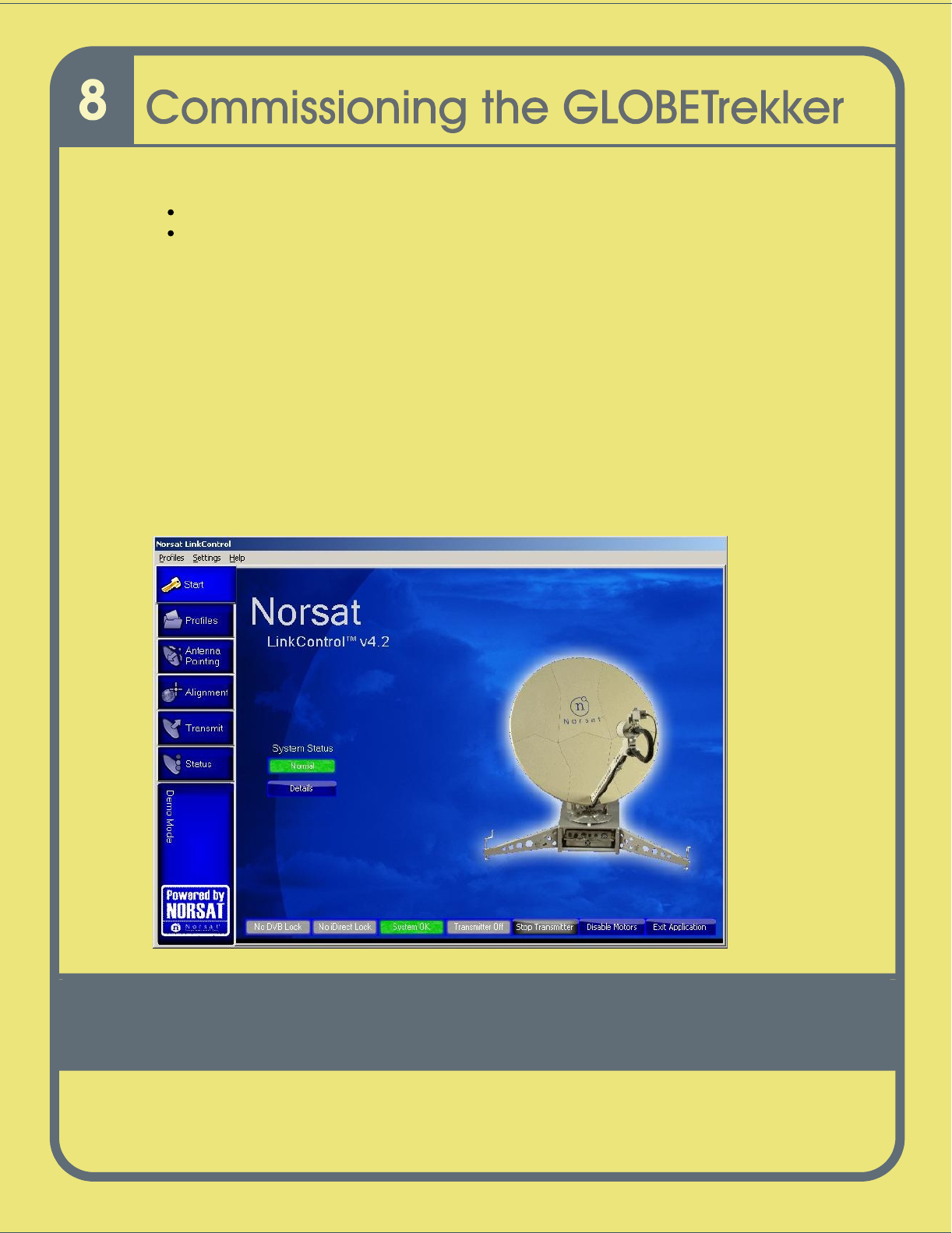
The screen below will appear on the
display
of the
laptop
wh
en the application is
launched:
Figure
15
Startup Screen

80
This process is password
-
protected and is accessible only to users designated as
"administrator(s)" in LinkControl.
If you are using the GLOBETrekker for the first time, the sys
tem will come with an
Administrator password. This can be changed at a later date
, although it is strongly
recommended you change and document your password
.
To enter Administrator mode:
1
On the Menu bar press Settings
-
> Enter Admin Mode
2
Enter the Admini
strator password. By default the password is “Administrator”.
Note: Passwords are case
-
sensitive
.
To exit Administrator mode and enter
Field
mode:
1
On the Menu bar press Settings
2
Select Exit Admin Mode

81
Step 2:
Call the Networ
k Operator
In order to verify certain settings, you will now call the Network Operation Center (NOC)
of the hub operator.
Go through the topics with the NOC in the sequence provided below:
a)
Confirm Satellite
Profiles:
Ask the Network Operator to confirm the characteristics of the satellite and transponder
you wish to use. Address each of the following with the Network Operator:
Satellite Name
___________________
(Transponder #; Slot #)
PROFILE INFORMATI
ON
Transmit Frequency
:
_______________
MHz
Receive Frequency
:
_______________
MHz
LNB Frequency Range
:
_______________
MHz
Polarization (Transmit)
:
_______________
(V/H)
Polarization (Receive)
:
_______________
(V/H)
SATELLITE
ALMANAC INFORMATION
Or
bital Position (Longitude)
_______________
(E/W)
Alignment / Beacon Frequency _______________
MHz
/ H or V
DVB
-
S carrier Frequency
_______________
MHz
/ H or V
NOTE:
For each satellite, there are five properties which relate to a “profile” saved (or
to
be saved) in the LinkControl application; and
three
properties which relate to the satellite
Almanac in the LinkControl application.
b)
Check
Modem
Software Version:
Ask the
hub
o
perator which software version the
network hub is using. The software vers
ion the hub is using needs to match the exact
iDS version
x.x.x
used by t
he built
-
in iDirect
iCo
n
nex
iNFINITI modem.
Verify the version
of
software you have and ensure the two are similar
.
If there is a difference between your version and that of the hub
operator, tell the hub
operator that you need them to send you the same version of the firmware and the
options files they are using. Once you have received the
files, proceed
with installing
them to your iDirect modem
.
c)
Obtain Options File
:
Ask the hub
operator to send you the latest options files. The hub
operator may ask you for certain parameters such as the modem serial number. You will
find these on a single label on the back panel
of the baseband unit
.

82
NOTE:
If you have recently used the same
hub operator and hub, you should ask the hub Operator if it is
still necessary to update the options files.
Refer to the
details
and profile
of your last transmission.
IMPORTANT:
Let the Network Operator know that you intend to use the terminal (modem)
in “
Mobile”
mode
.
The alternative mode is the non
-
mobile mode. The “Mobile” mode gives you the flexibility to
operate at the edge of a footprint.
Step 3:
Create or Edit Profile
The Link Control Applic
ation relies on a Profile to orient the antenna and peak on the
satellite. It is important to ensure that the Target Satellite information provided
by the
hub operator
in Step 2 (
b)
;
described in section
Step 2: Call the Network Operator
in
this chapter
;
m
atches
an existing
p
rofile.
If there is no match, then you will create or edit
an existing profile.
Call
Up
E
xisting
P
rofiles and Compare:
a)
Click on the Profiles tab on the left side of the screen; refer to
Figure 17
Startup
Screen
.
b)
Click
on
a
profile i
n the list of profiles under
Choose a profile.
c)
A summary of the selected profile is displayed on the right side of the screen.
d)
Compare the information (target satellite, polarization, GPS
coordinates and
LNB
to use) provided by the Network Hub operator with the existing profile data.
e)
If there is a perfect match
, p
roceed to Step 4
, otherwise go to step f).
f)
If there is a difference in the information provided by the Network Hub Operator
and that found in the Profiles,
then
you must decide whether to crea
te a new
profile or edit an ‘existing profile”. If you do not plan to use the existing profile
ever again, then you may wish to edit an existing profile. Otherwise, create a new
profile.

83
Create or Edit a Pr
ofile
a)
To create or edit a profile,
when in Administrator Mode
, press
the
Profiles
tab on
the
LinkControl
m
enu
bar.
To Create a NEW Profile:
Select
Add New Profile
.
To Edit and Existing Profile:
Select
Edit Existing Profile
and make your
selection from t
he listed profiles.
Hint: You can also
click
the Profiles
button
from the Profile tab along the left side
of LinkControl and then make your Profile selection under
Choose a
p
rofile
from
the right
-
hand side of the screen. If you use this method, click on
S
ave these
settings as
… button OR highlight a profile, click
Edit T
his Profile
at the bottom
of the Profile Details window. Create or modify to your desired settings, then
save the Profile with
its
new name.
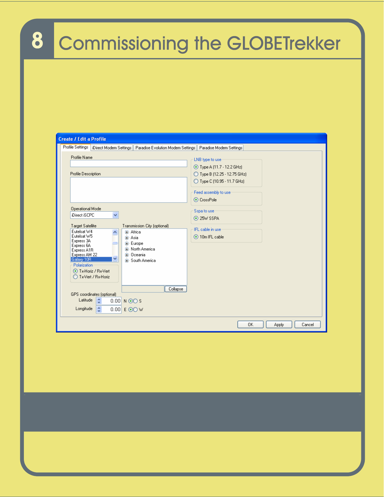
b)
The
Profile
Settings Screen
opens as shown in
Fi
gure 18
Create / Edit a
Profile Screen
.
c)
To
create
the
new
profile, enter a profile name in the
Profile Name
text box.
d)
Enter a brief profile description in the
Profile Description text box.
e)
Select an operational mode from the
Operational Mode
drop down b
ox.
If you
skip this step in error, you will get an Application Component error message
f)
Choose a target satellite from the
Target Satellite drop down box.
g)
Click under
Polarization
to select the type of transmit polarization
.
Note:
Optional
-
Choose the
city of transmission from the
Transmission
City
scroll box
.
OR
Note:
Optional
-
Choose latitude and longitude coordinates from the
Latitude
and
Longitude
scroll boxes and radio buttons
.
h)
Choose the LNB that is applicable for your transmission location
from
LNB type
to use
.
84
i)
Choose the
feed assembly under
Feed assembly to
use
(only if more than one
choice is listed)
.
j)
Click to select a SSPA under
SSPA to use
(only if more than one choice is
listed)
.
k)
Click
Apply
.
Figure
16
Crea
te / Edit a Profile Screen
Figure 18
Note: The different modem tabs displayed in
Figure 18
above may vary on
your GLOBETrekker system, depending on which configuration you have purchased.
If you purchased a GLOBETrekker with the iDirect modem, then you
will see the iDirect
Modem tab; if you have purchased a GLOBETrekker with a Paradise modem, then you
will see the Paradise modem tab.

85
Step 4:
Edit
/Review
Satellite Almanac
a)
On the
Menu
bar, press
Settings
E
dit Satellite Almanac
b)
On the left hand side, find the
Target Satellite
and click on it.
c)
If there are any differences in the alignment carrier, DVB
-
S carrier or orbital
position then you can modify them
or add new carriers
.
d)
Click on the
CLOSE
button wh
en you are done.
To Add a New Carrier:
1.
Enter the Description, Frequency, Polarization, Carrier type and Symbol Rate;
(Symbol Rate is always 0 (zero) for Alignment Carriers); for the new carrier inside
the Carriers sub
-
window on the right
-
hand side.
2.
Clic
k Apply, Change on the Carriers sub
-
window.
3.
The new carrier will appear in the list.
To Edit an Existing Carrier:
1.
H
ighlight the entire row, (click on the cell in front of the row describing carrier), for
the carrier you wish to modify from the list.
2.
Ed
it the desired parameter for the carrier.
3.
Click Apply change
in the C
arriers sub
-
window.
To Delete a Carrier:
1.
Highlight the entire row, (click on the cell in front of the row describing carrier), for
the carrier you wish to modify from the list.
2.
Click
on Delete in
the C
arrier
s
sub
-
window.
When you have finished working with the Carriers, click on Apply Change in the upper
right
-
hand corner to update the Satellite information.

86
Step 5:
Load
Modem
Options File
O
nce you have received the options file
and loaded it onto a USB memory stick
, insert
your memory stick in the USB port on the back panel.
An
“
options file
”
is a
file created by the Hub Operator for a TDMA network and is
configured specifically for access
to that Hub Operator’s network. It contains information
about the TDMA network, your modem and satellite access information.
1
Choose the profile.
2
Click on
Edit This Profile
.
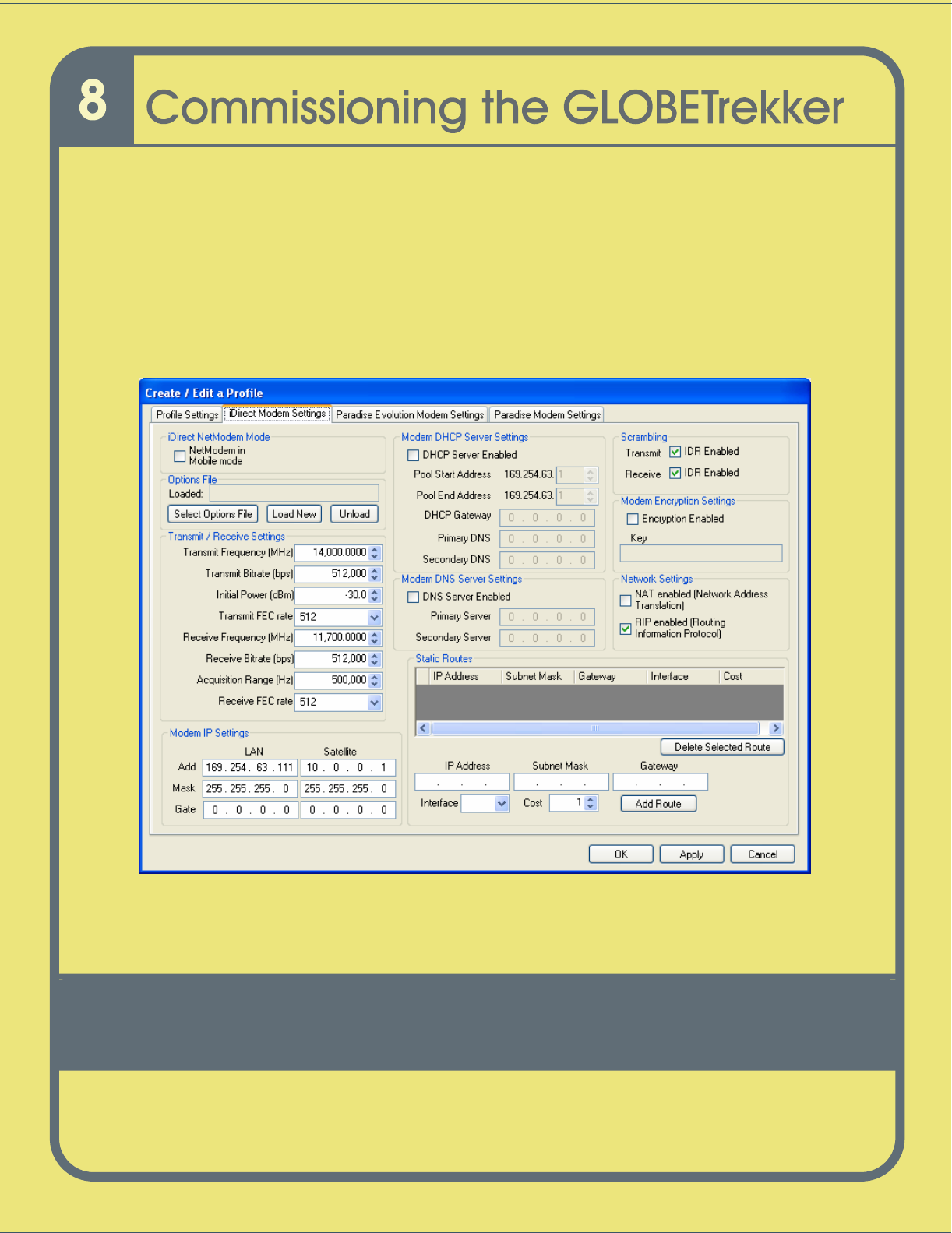
3
Click on
iDi
rect modem settings
.
4
In the second box from the top entitled
Option
s Files
,
then c
lick on
Load
New
.
5
Select the file from your directory
.
6
Select Apply to save settings.
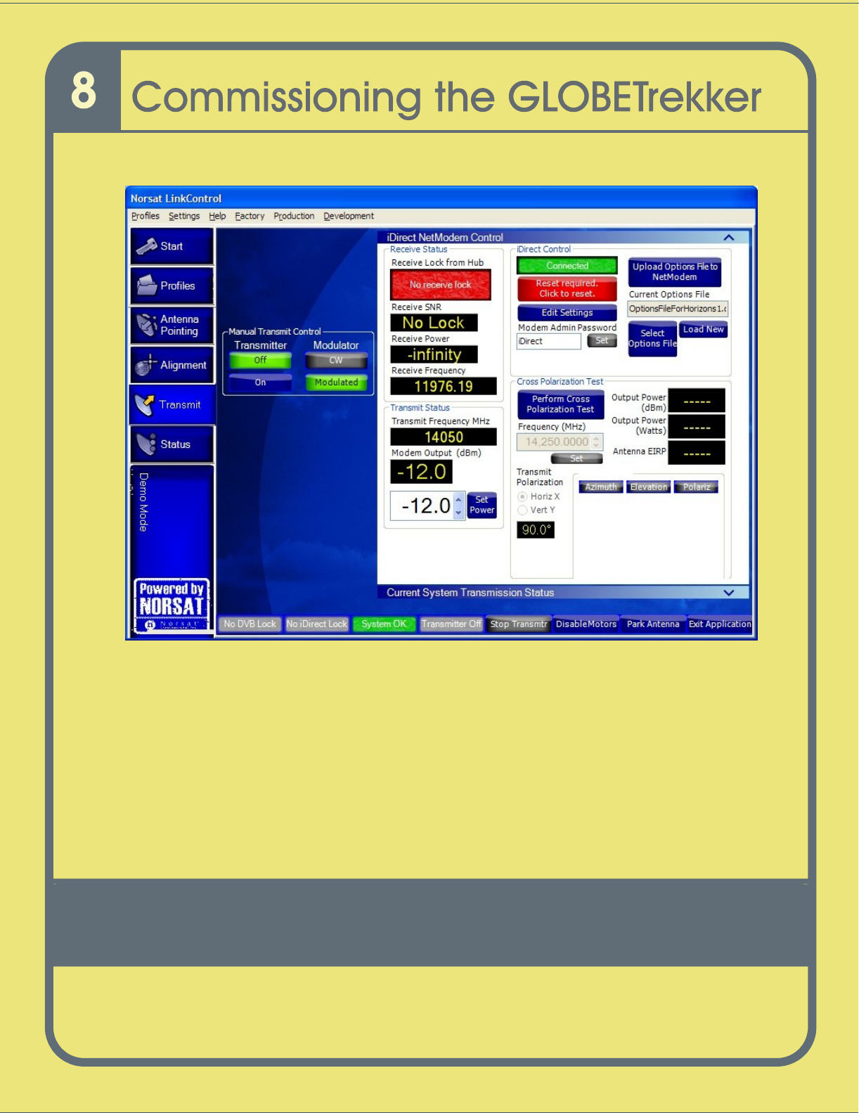
Reboot
the modem
1
Go to
the
iDirect Modem Control
sub
-
screen from the
Transmit tab
as
shown in
Figure 19
Transmit Screen
.
2 I
n the
iDirect NetModem
Control
s
ub
-
screen,
c
lick on
the
Upload Options
File
to NetModem
button to load your options file. If the button is greyed out
and the “
Reset Required. Click to Reset
”
button is red, click on it first, then
click the
Upload Options File to NetModem
button.
87
Figure
17
Transmit Screen
88
Step 6:
Set Modem Parameters (SCPC)
This step is required only if you are operating in SCPC mode.
To set Tx and Rx frequencies for th
e Modem
:
1.
C
lick the
Profiles
tab. Choose a Profile
2.
Edit this Profile or Save these settings as…
3.
Click on modem settings. The
Modem Settings Screen
opens as shown in
Figure
20
iDirect NetModem Screen
.
Figure
18
iDirect NetModem Scre
en
4.
Enter new Transmit and Receive frequency,
Bitrate
and other parameter as
required.
5.
Click on Apply and then OK.

89
Step 7:
Exit and Restart LinkControl Application
Click on
Exit Applicatio
n
on the bottom right
-
hand side
of any LinkControl screen
to
allow the settings to take effect.
You have now completed the commissioning of the GLOBETrekker. If you plan to
operate using the auto
-
acquire function of LinkControl, proceed to Chapter 9. If
you plan
to use the manual mode of acquiring the satellite proceed to Chapter 11.

90
This page left intentionally blank.

91
Operating the GLOBETrekker in Auto-
Acquire Mode
Starting the Sess
ion
...................................................................................................
92
Initializing the Compass
.............................................................................................
93
Pointing the Antenna
..................................................................................................
94
Transmitting the Signal
...............................................................................................
96
Ending Transmission
..................................................................................................
96
92
The chapter explains how
you can leverage
LinkControl
’s
auto-
acquire capability
to
point
and peak your antenna to the correct satellite
.
Hint:
Before
using the
auto
-
acquire function for the GLOBETrekker; ensure a profile
has been setup for the desir
ed satellite.
In order to create a profile for the satellite, the
user must be logged in with Administrator rights
and operating in Administrator Mode
which
is
outlined in Chapter 8.
Once a profile has been selected the user must exit
Administrator Mode an
d be operating in Field Mode.
The profile must contain enough
information
about the
location of both the
desired satellite
and the GLOBETrekker
system in
order to successfully locate it (Satellite name, alignment/beacon
and DVB
-S
carrier
s;
GPS coordinates
for latitude and longitude).
Starting t
he
Auto
-
Acquire
Session
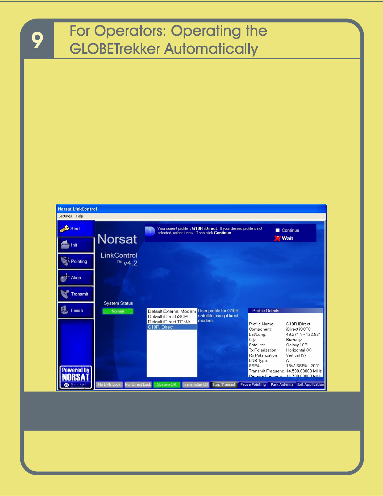
Once LinkControl starts, the
Startup Screen
is launched,
as shown in
Figure 21
;
this
startup ‘mode’ is
known as
t
he
Field M
ode
.
Follow the instructions
on screen
.
To start
the auto
-
acquisition process,
click on a profile to select it, verify the details are correct
under Profile Details
and
click
the
Continue
box
.
Figure
19
Startup Screen
It is recommended the user checks that the system is level before operating the
LinkControl software.
93
Note:
If you
would like to change
your
selected
profile,
simply click on the
Wait
box. This
brings you back to the beginning
where you can select another profile
.
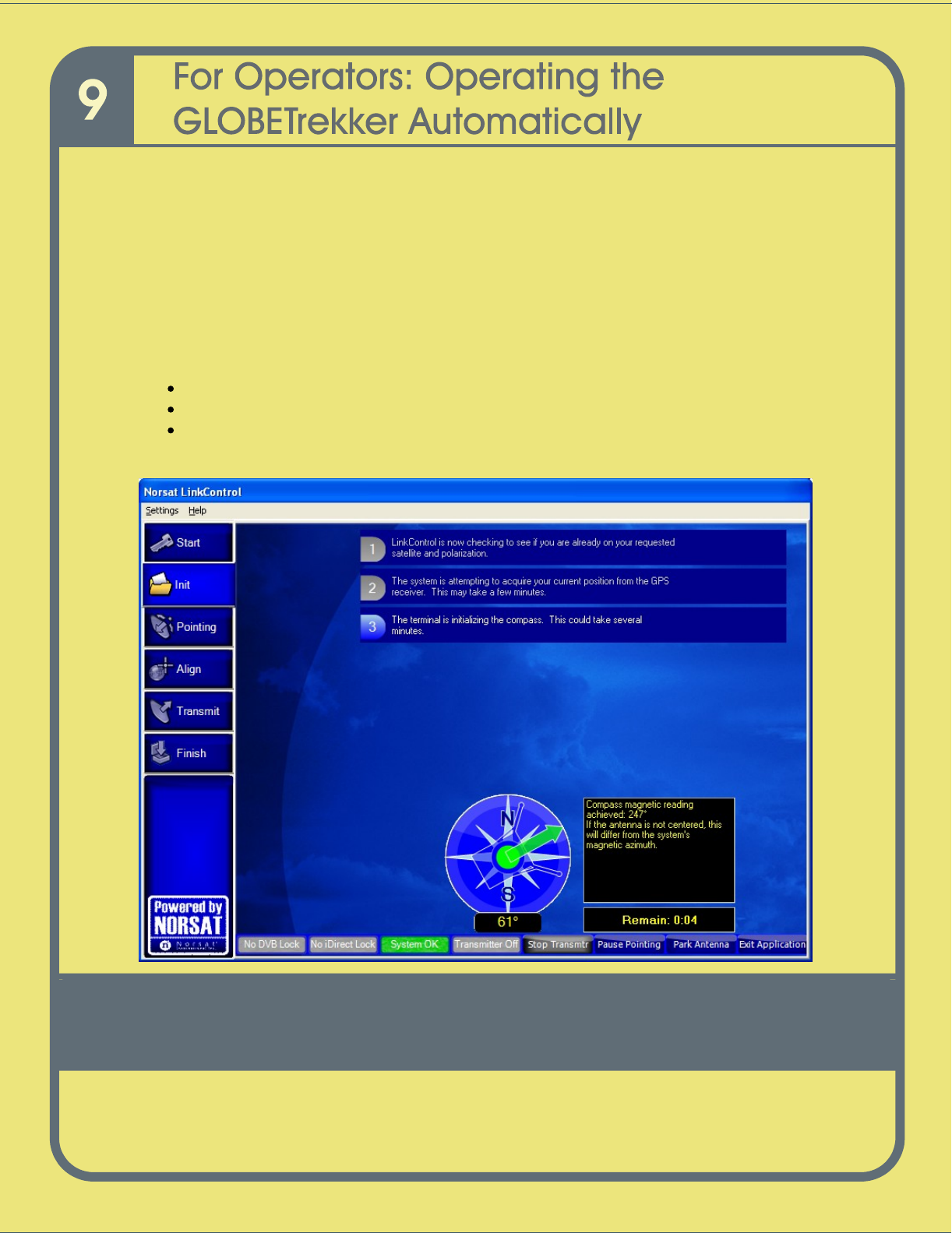
Initializing t
he Compass
The
Initializing the Compass Screen
opens as
shown in
Figure
22
.
There should be no user interaction required
on this screen
. If the
Compass or GPS
Receiver does not return valid data
, Link
Contr
ol will advise
and instruct you
on
how to
proceed.
Note: The initialization process goes through the following steps:
checks to see if the GLOBETrekker is already on the desired satellite
acquires GPS readings for your current position
it initializes the compass.
Figur
e 20
Initializing the Compass Screen
94
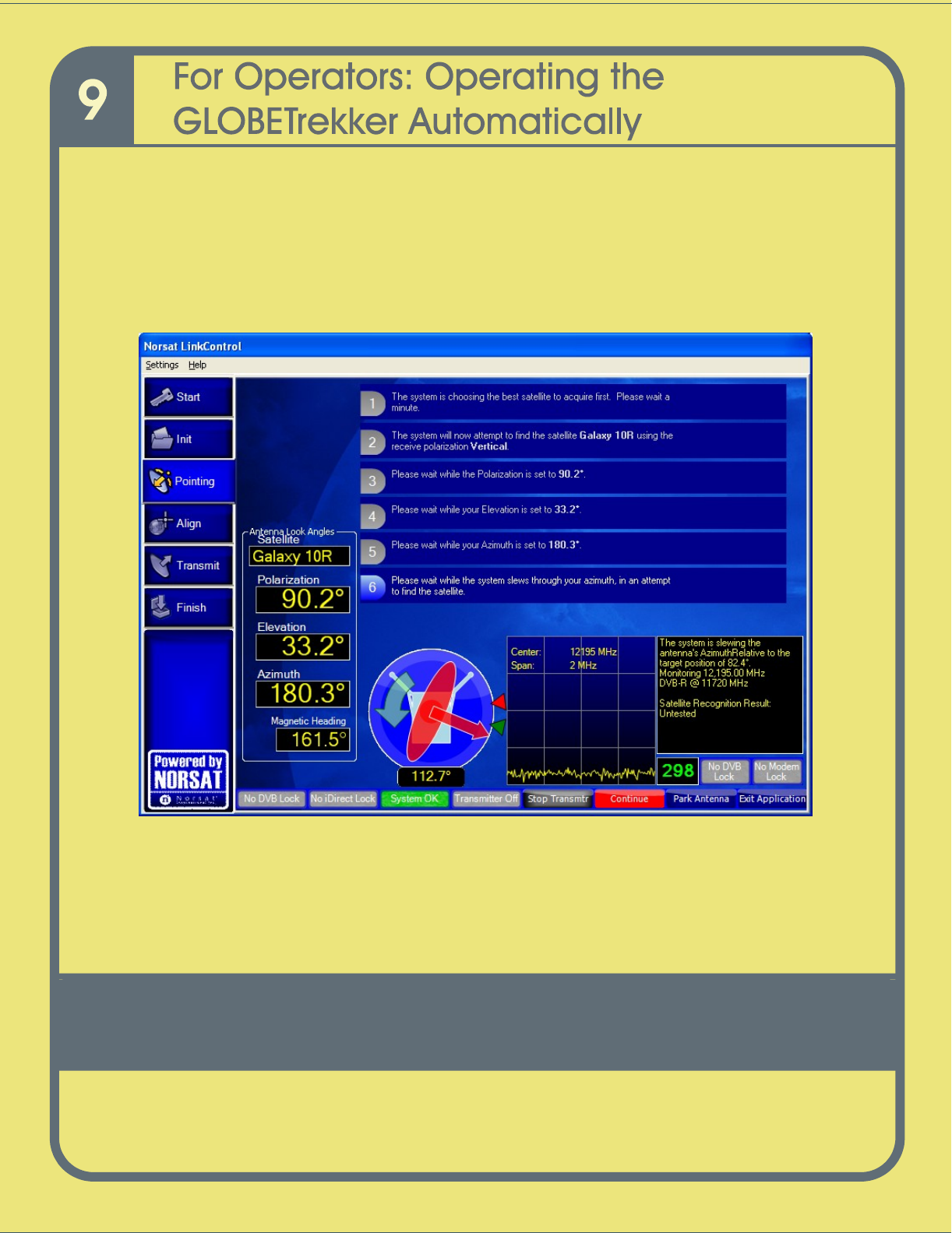
Pointing t
he Antenna
The
Pointing the Antenna
Screen
1
opens as shown in
Figure 23
.
There should not be
any information to enter,
nor interactio
n with the terminal, unless there is a problem. If a
problem occurs, follow LinkControl’s instructions.
Figure
21
Pointing the Antenna Screen 1
Figure 23
shows that the antenna is rotating
; in Azimuth;
to find a Rx
(receive)
antenna
signal from the satellite.
The
DVB Lock
and the
Modem Lock
are not engaged at this
stage.
T
o view the
Pointing the Antenna Screen 2
with locks engaged, refer to
Figure 24
.
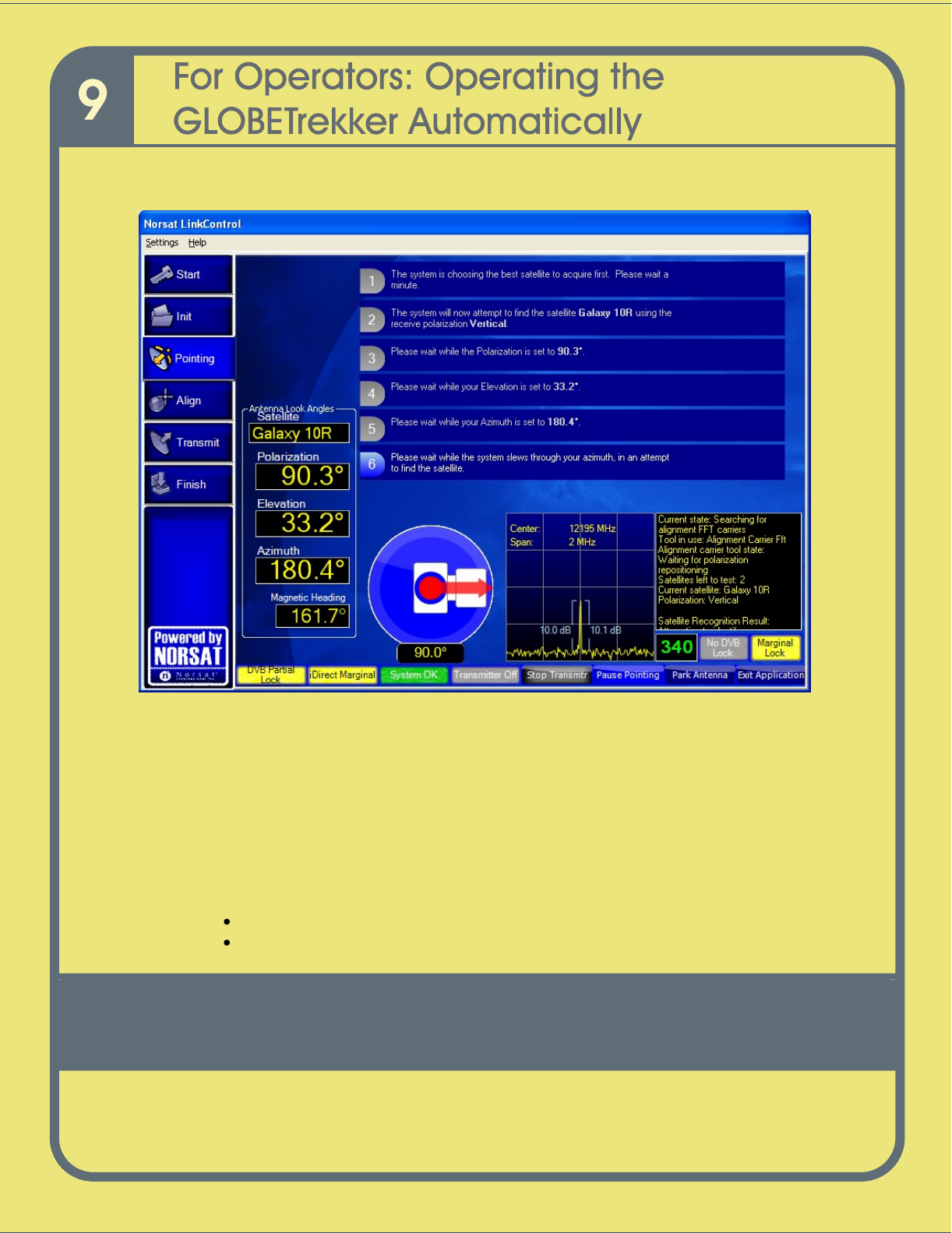
95
Figure
22
Pointing the Antenna Screen 2 with
locks engaged
As shown in
Figure 24
, the
Marginal Lock
indicator
, (the
yellow box
to the right of the
number
340
which is the signal strength indicator),
turn
s
yellow
; (along with the DVB
Partial Lock and iDirect Marginal boxes on the left
-
hand side);
when the antenna
initially
detects the signal from the satellite, but has not found the exact location of the
satellite.
The antenna will
attempt to
zero in on the strongest point of the signal and will fully lock
on.
Note:
The
color of the following ind
icators on the
Status and Control
Toolbar
also
changes
to yellow:
DVB Partial Lock
i
Direct Marginal
(applicable only to iDirect modems)
96
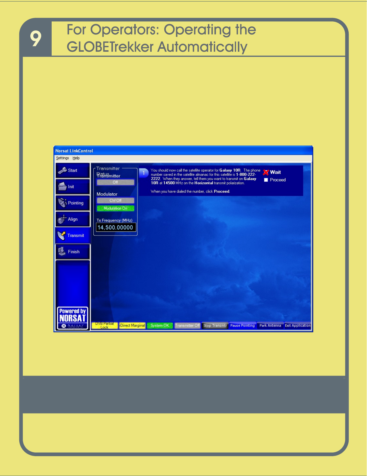
Transmitting t
he Signal
When the terminal is ready to transmit, t
he
T
ransmit
s
creen
opens as
shown in
Figure
25
.
Before
you
can start transmitting
you
must
call into the Network Operations Center
to
gain access to the satellite by negotiating satellite access with
the hub
o
perator
.
Chapter 10 will demonstrate how t
he LinkC
o
ntrol wizard guides
you through these steps.
Follow the instructions on the LinkControl
screen
to call into the operator and start your
transmission
.
Figure
23
Transmitting Screen
Ending
Transmission
If you need to end or stop your transmission at any time
, you can
do so from the
Finish
screen. To access the
Finish
screen, c
lick
Finish
button on the left side menu
. The
Finish Screen
opens. Follow the instructions.

97
Satellite Access Procedures
Satellite Access Protocol
............................................................................................
98
The Call
......................................................................................................................
99
Sample Script for Telephone Conversation with Satellite Operator
.........................
111
98
This c
hapter
describes how a user operates in auto
-
acquire mode, should access the
satellite and interact with the hub operator.
S
atellite Access Protocol
Before
you
can begin transmitting over a satellite,
you
must
go through a Satellite
Access Procedure, or an “Uplink Operator’s Procedure.” This procedure involves calling
into the Network Operation Center (NOC) of the
Hub Operator; or
Satellite Operator
(SO) if in SCPC mode; and responding to their requests for info
rmation and/or action.
You
must follow the instructions of the
hub operator
or risk the possibility of fines.
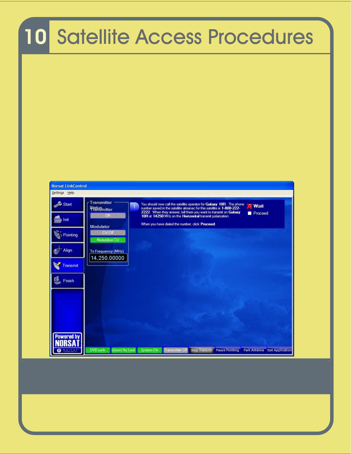
Th
e following
screen in LinkControl
w
ill tell
you when to call the
hub
o
perator. NOCs
generally advise
you to
call 10 to 15 minutes before
the s
cheduled
transmission
time
.
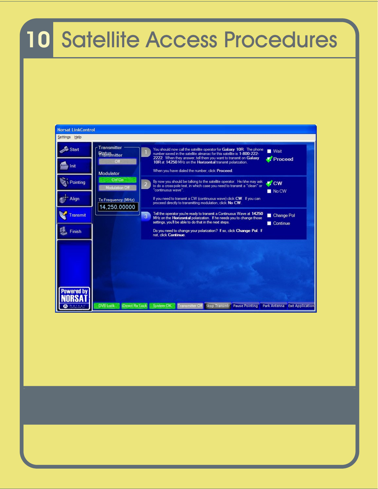
These screens will help walk
you
through the call with the
NOC.
Figure
24
Satellite Acces
s Procedure Screen
–
Call NOC
99
Hint
:
Have the phone number for the
Network Operations Center (hub op
erator
/SO
)
ready in advance.
When you are ready to call, click the Proceed button as shown in
Figure 26
.
The Call
1
You
should:
i.
Identify
yourself
and
provide your lo
cation
ii.
Indicate that you
have scheduled satellite time
iii.
Indicat
e
the
purpose of
your
transmission (example: data transfer)
iv.
Indicate that you are ready to start transmitting on satellite, transponder and
frequency slot allocation (example: NSS7, Transponder K18, Slot C)
The
hub
operator may in turn verify some paramet
ers and ask some questions.
You should be able to find most of these answers without having to resort to
administrator mode.
Such parameters/ questions may include:
Are you aligned and peaked on the satellite?
Modem settings
Confirm
Uplink
frequency and
polarization
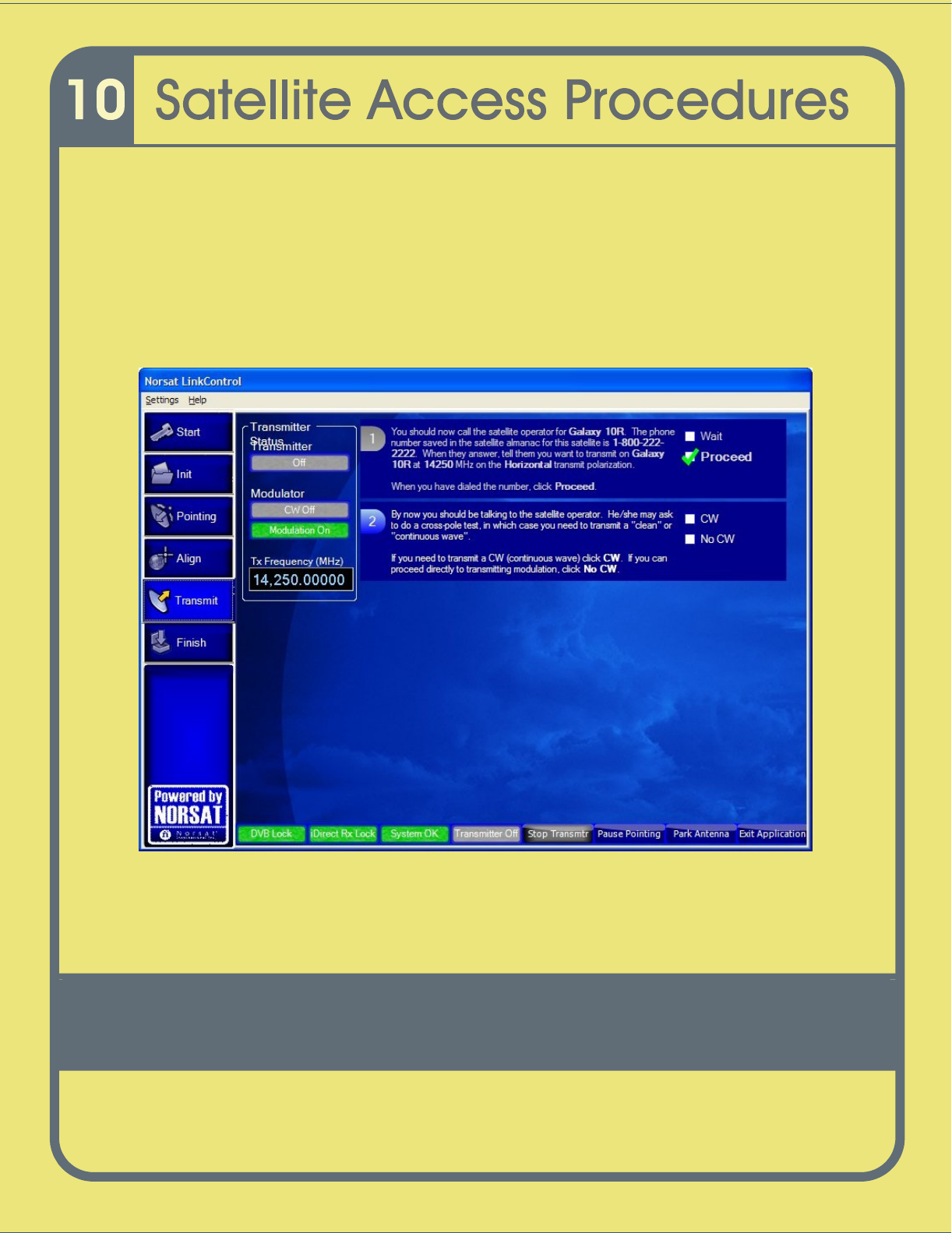
2
The hub
o
perat
or may then ask
you to conduct a “c
ross pol
test
”.
Y
ou may be asked for
to bring up
a “clean carrier” (or “unmodulated carrier” or
“continuous wave” or “CW”) at low power.
100
3
Click
the
CW
box as shown in
step 2 of
Figure 2
7 i
f you are
asked
to
complete
this
step
.
If he doesn’t ask you to complete this step and simply asks you to proceed
directly to transmitting mode click the
No CW
box.
Note:
LinkControl will then guide you through the rest of the CW transmission
process.
Figure
25
Satellite Access Procedure Screen
-
CW
101
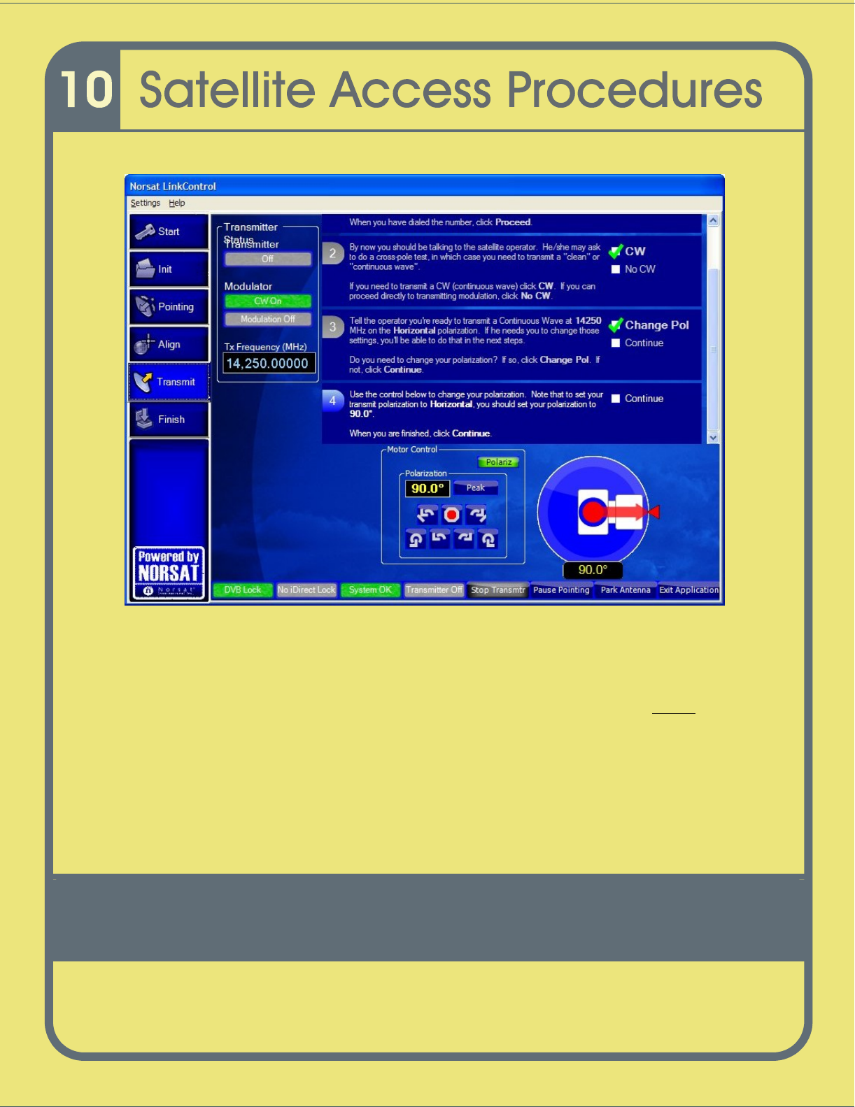
4
The
hub o
perator may then ask you to adjust your polarization. LinkControl will
provide yo
u with the option to change your polarization as
shown in
Figure 2
8a.
LinkControl th
en opens the polarization adjustment controls as shown in
Figure 2
8b.
Figure
26
a
Satell
ite Access Procedure Screen
–
Change
P
olarization
102
Figure
28
b
Satellite Access Procedure Screen
–
Change Pol
arization
5
When you are f
inished with the polarization adjustment
, or are not asked to adjust
your polarization
, click
Continue
.
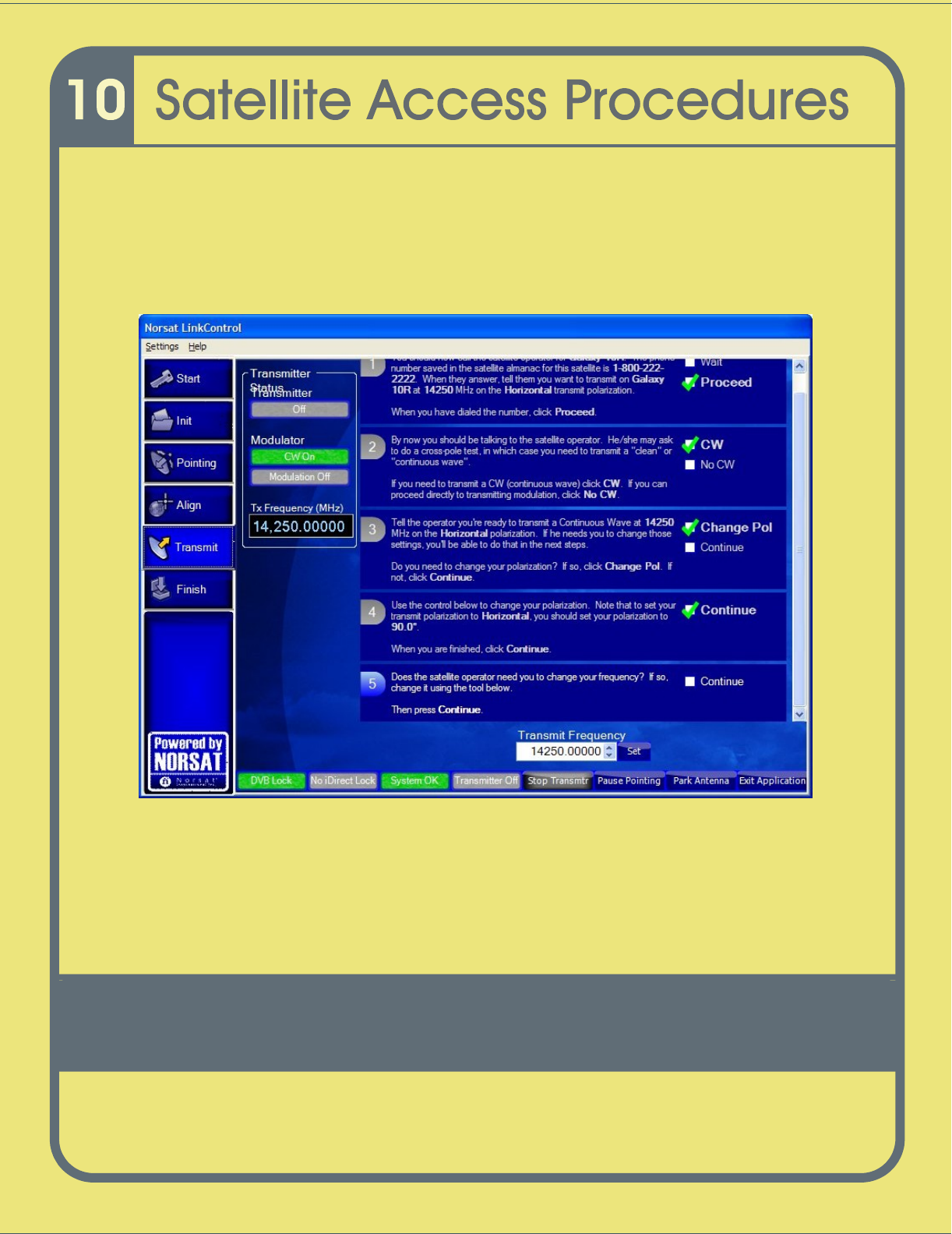
Hint: If you are asked to make an adjustment to your Transmit Frequency
before
your polarization, simply click
Continue
at Step 3 (
Figure 2
8
) which bri
ngs you to
the
screen
which allows you to change the transmit frequency. Once frequency
adjustment completed you can go back to Step 3 to make your polarization
adjustment should the hub operator ask you to do so.
103
6
You may be asked to change your transm
it
frequency. LinkControl will present you
with the
Transmit Frequency
display
which you can change with the “up” and
“down” arrows
as shown in
Figure 2
9.
When finished adjusting the frequency, click
the
Continue
box.
Figure
27
Sa
tellite Access Procedure Screen
–
Change Transmit Frequency
104
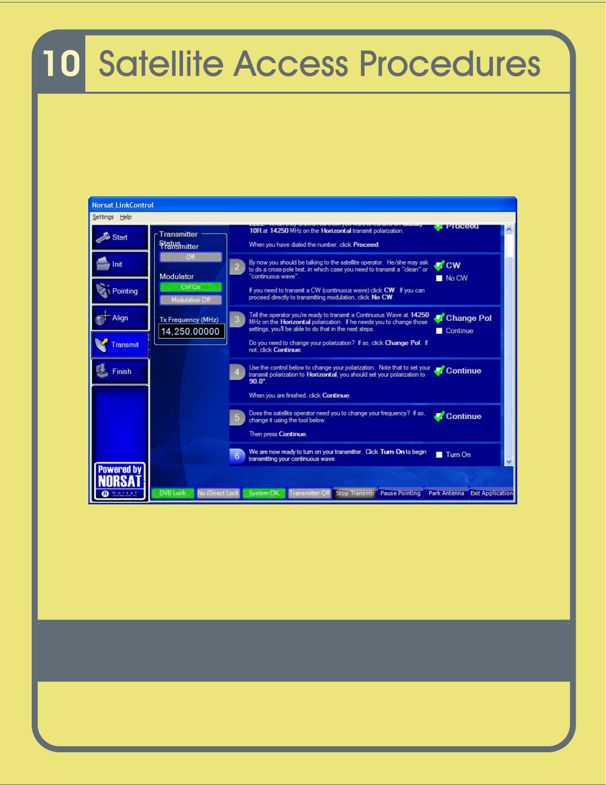
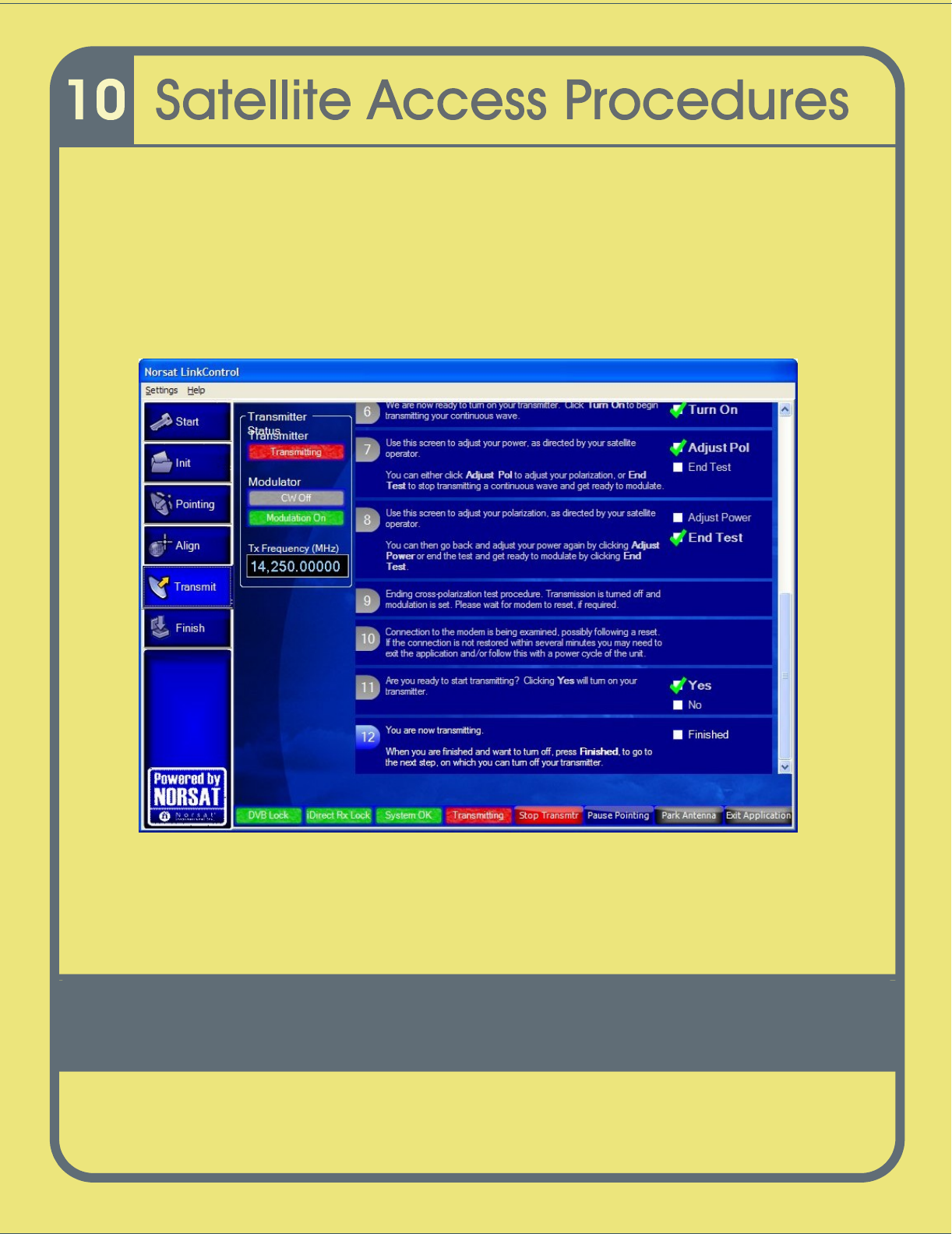
7
The transmitter is now ready to be turned on. Click the
Turn On
box when you are
ready as shown in
Figure
30
to power up your transmitter
.
Figure
28
Satellite Ac
cess Procedure Screen
–
Turn on Your
Transmit
ter
8
Once you click on the Turn On button, you are transmitting and are then presented
with the next screen to adjust your output power level as shown in
Figure 31
.
105
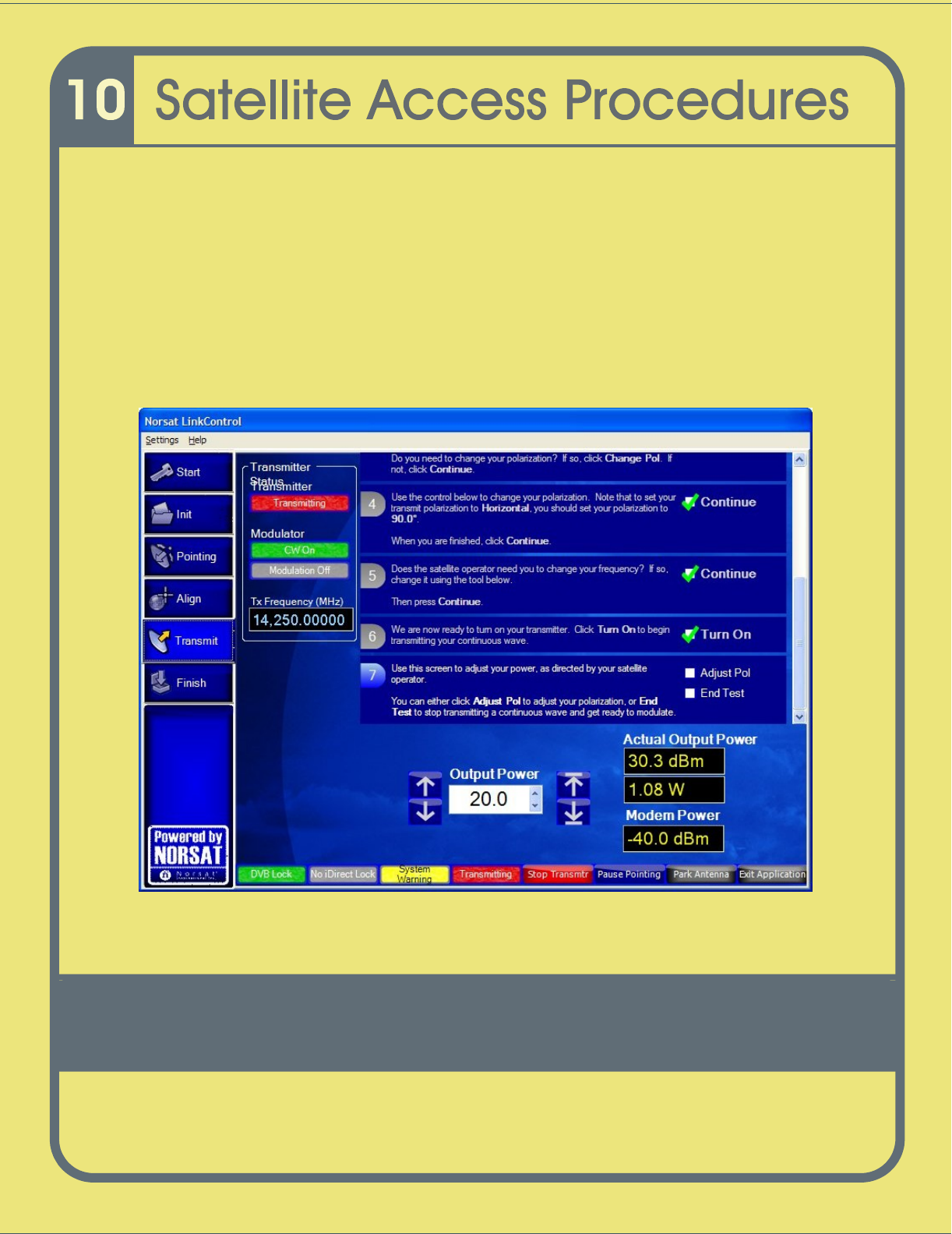
9
The hub operator
may
also ask you
to adjust your power level.
When dire
cted, slowly
increase power to
operating level and stop.
Figure
31
displays the power control
adjustment control in the lower part of the
screen.
Hint: Under the guidance of the hub operator, use the buttons to the left of
the
Output Power
display to adjust the power level in 1.0 dB steps and use the buttons
on the right of the
Output Power
display to adjust the power in 0.1 dB steps. Watch
the results in the Actual Power Output
display area.
Figure
29
Satellite Access Procedure Screen
–
Adjusting
Your
Output
Power
106
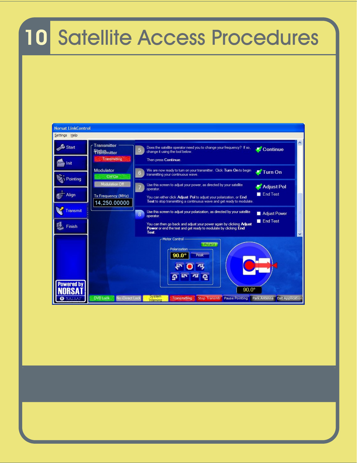
10
The hub operator may ask you to re
-
adjust your polarization. If asked to do so, click
the
Adjust Pol
box as shown in
Figure
32
a
Step
7
(t
he Motor Control for Polarization
adjustmen
t opens as in
Figure 32
a)
otherwise click the
End Test
box
.
If you are not asked to adjust your polarization
or your power
click the
End Test
box
as shown in
Figure
32
a
Step 8.
Figure
30
a
Satellite Access Procedure Screen
–
Adjus
ting Your Output Power
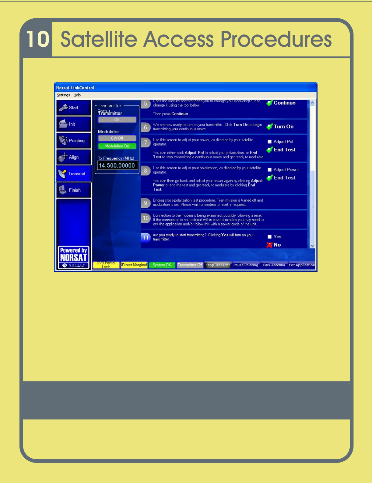
11
Once you have clicked the End Test box
, see
Figure 32b
, the system ends the cross
pol test, turns transmission of and sets modulation. It then connects to your modem.
107
Figure
32b
Satellite Access Procedure Screen
–
End Test
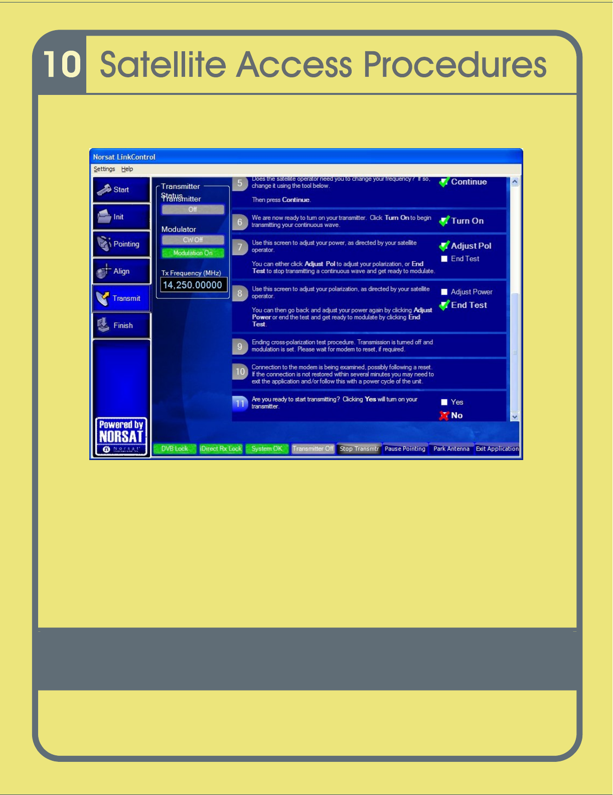
12
LinkControl then presents
Figure
33
Step 11 which provides the interface to turn the
transmitter on only when instructed to do so by the hub operator.
13
Wait
for further instructions from the Satellite Operator while carrier specifications are
checked by t
he network operator.
108
Figure
31
Satellite Access Procedure Screen
–
Ready to Start Transmitting
14
When directed, modulate the signal (start transmitting)
by clicking the Yes box as
shown in
Figure
33
Step 11.
15
Wait
for furt
her instructions
from the
hub
operator
while carrier specifications are
checked
.
16
The NOC will verify your phone number and the end time for your uplink. The
controller will remind you to call the NOC again just before the end of the uplink (
the
“goodn
ight
call
”
).
109
Goodnight Call
The purpose of the Goodnight Call is to inform the NOC that you have completed your
transmission and that you
wish to end your transmission.
1
Once you confirm end of transmission
with the hub operator
, click the
Finished box
as
shown in
Figure
34
, step 12.
Figure
32
Sate
llite Access Procedure Screen
-
Transmitting
110
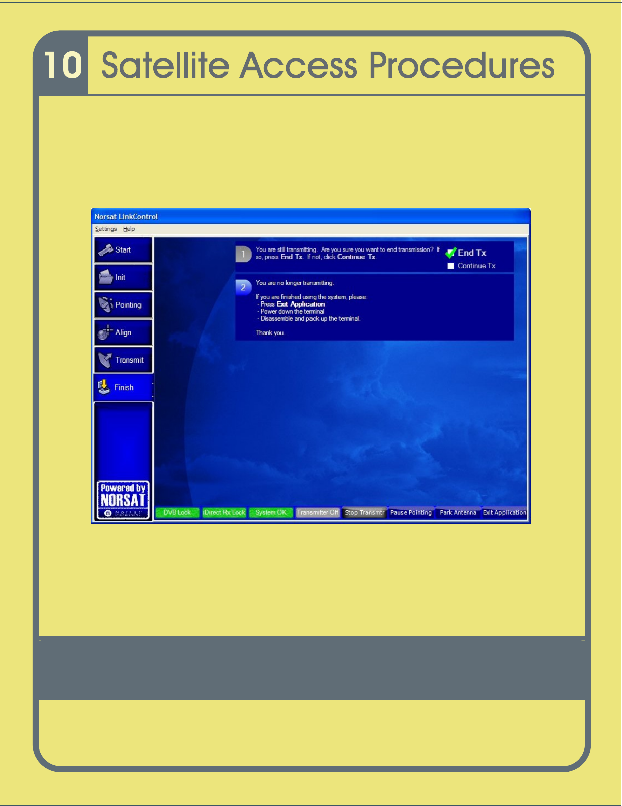
2
You will then receive an
End Transmission
confirmation as shown in
Figure 3
5
.
Once you click the End Tx box, the transmitter will be tu
rned off and you will receive
a “
You are no longer transmitting.
”
Message confirming this.
Figure
33
Sate
llite Access Procedure Screen
–
End Transmission