Novatel Wireless NRM-3800 CDPD Data Transceiver User Manual Vespa AT Command Set Reference Guide 0 1
Novatel Wireless, Inc. CDPD Data Transceiver Vespa AT Command Set Reference Guide 0 1
Contents
- 1. Manual
- 2. Another Manual
- 3. Revised Manual Page 13
- 4. Manual Changes
Another Manual


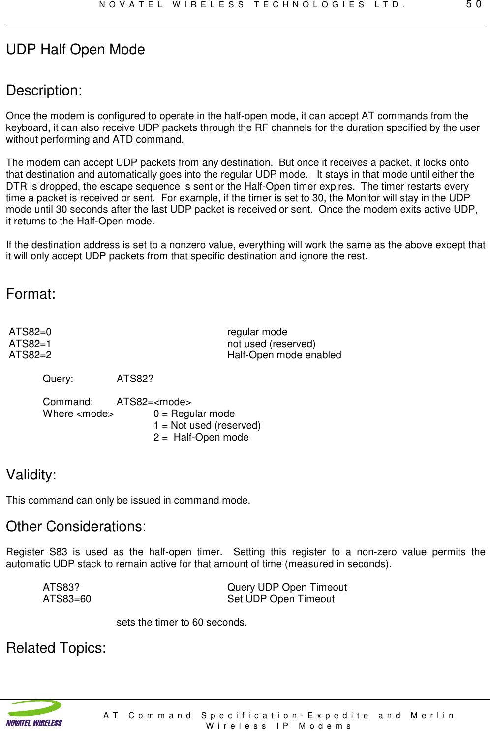
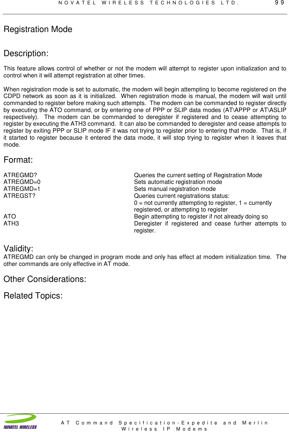
![NOVATEL WIRELESS TECHNOLOGIES LTD. 11AT Command Specification-Expedite and MerlinWireless IP ModemsUDP Mode DescriptionUser Datagram Protocol is a basic transport protocol that provides a best-effort, connectionless deliveryservice with minimum overhead. The protocol does not guarantee delivery of packets. There is nochecking or retransmission of the data packets. It does provide minimum overhead as it only adds thesource and destination port numbers to the header. Since the protocol is unreliable, the application mustprovide checking, acknowledgments and retransmissions if the data is critical. In many applications, thedata is not critical because updates are sent periodically and occasional losses can be tolerated.UDP sessions may be originated by the local application host or by the network. The DTR signal must beasserted or S211=1 (pretend DTR is always asserted) for the unit to enter into a data communicationssession. The session is terminated by dropping DTR or resetting the unit.UDP Modes of OperationCommand: ATS82 = <mode>Where <mode> = Timer value in seconds0 = Regular mode1 = Not used (reserved)2 = Half-Open modeOriginating a UDP SessionA session is originated by the application host issuing the ATD (Dial) command:ATDPnnn.nnn.nnn.nnn/pppppATDP specifies a UDP session. nnn.nnn.nnn.nnn is the destination IP address and ppppp is thedestination application port number. If no port is specified then a port number of 0 is assumed. It shouldbe noted that UDP and TCP make extensive use of port numbers, please be aware that the modem willuse the port number as a criteria for accepting and passing data to the host application.CONNECT [terse 1] result code will be issued and all ensuing data sent from the host application will beassembled into a UDP packet and transmitted to the destination application.ERROR [terse 4] result code will be generated if the modem is not currently registered on a CDPDnetwork.PAD (Packet Assembly and Disassembly) function will transmit data when the inter-character idle time-outoccurs or when the PAD buffer is full. (256 or 512 bytes). The idle time-out is specified in register S50 in1/10 seconds.Receiving Data - Once the session is started, any packets sent to the modem's IP address with the portnumber specified in register S110 will be processed and the data portion will be transmitted over the seriallink to the host application. Any packets received with a different port number specified will be discarded.Termination - The session is terminated by dropping DTR or resetting the unit.](https://usermanual.wiki/Novatel-Wireless/NRM-3800.Another-Manual/User-Guide-80601-Page-11.png)
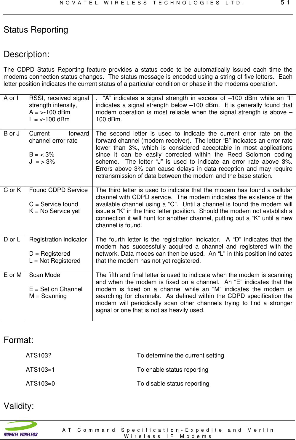
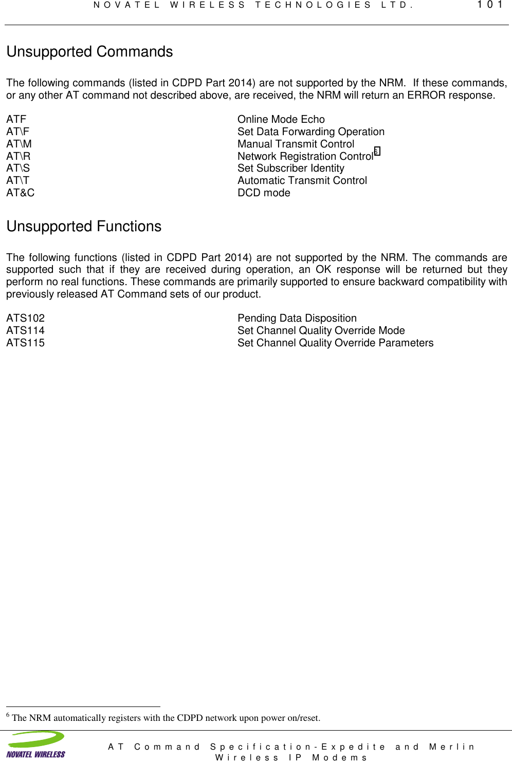
![NOVATEL WIRELESS TECHNOLOGIES LTD. 12AT Command Specification-Expedite and MerlinWireless IP ModemsTCP Mode DescriptionTransport Control Protocol, is a reliable, connection-oriented transport protocol that usesacknowledgments and retransmissions to guarantee delivery. This is an obvious advantage forapplications where the data is critical and the application cannot provide the required reliability. There ismore overhead in the protocol to provide this reliability, making it less efficient than UDP. For larger datatransfers, TCP is the easiest protocol to use to get reliable service.TCP sessions may be originated by the local application host or by the network. The DTR signal must beasserted or S211=1 (pretend DTR is always asserted) for the unit to enter into a data communicationssession. The session is terminated by powering the modem off, dropping DTR or by the remote hostterminating the connection. If the session is terminated by a power down, the remote host may not teardown its part of the session properly, leaving the remote host waiting for further information for thatsession. This can pose problems for some applications. Care in session tear down is essential forreliable operation.TCP Modes of OperationTCP Listen mode is established by having S0=1 when the modem powers up. . The port specified inS110 will be used for the TCP Listen mode. The DTR signal must be asserted or S211=1 (ignore signal onDTR pin and proceed as if DTR is always asserted) for the unit to enter into a data communicationssession. When a connection request for the correct port is received by the modem, the modem willestablish the connection notify the local host with:Verbose TerseRING 2CONNECT 1and begin the TCP session.Termination - A TCP connection is terminated by dropping DTR, or by the remote end of the TCPconnection terminating the session.Originating a TCP Session A session is originated by the host application by issuing the ATD (Dial) command:ATDTnnn.nnn.nnn.nnn/pppppATDT specifies a TCP session. nnn.nnn.nnn.nnn is the destination IP address and ppppp is thedestination application port number. The modem will attempt to establish a connection with the destinationhost. If it is successful, a CONNECT [terse 1] result code will be issued and all ensuing data sent from theapp host will be assembled into a TCP packet and transmitted to the destination application.ERROR [terse 4] result code will be generated if the modem is not currently registered on a CDPDnetwork.Connection Failure will be signaled by a BUSY [terse 7] result code, and may be caused by one of thefollowing:- Wrong IP address or port number- The destination device does not have a TCP Listen process open on the port specified.- The destination host already has a connection established with another client on the specified port.](https://usermanual.wiki/Novatel-Wireless/NRM-3800.Another-Manual/User-Guide-80601-Page-12.png)
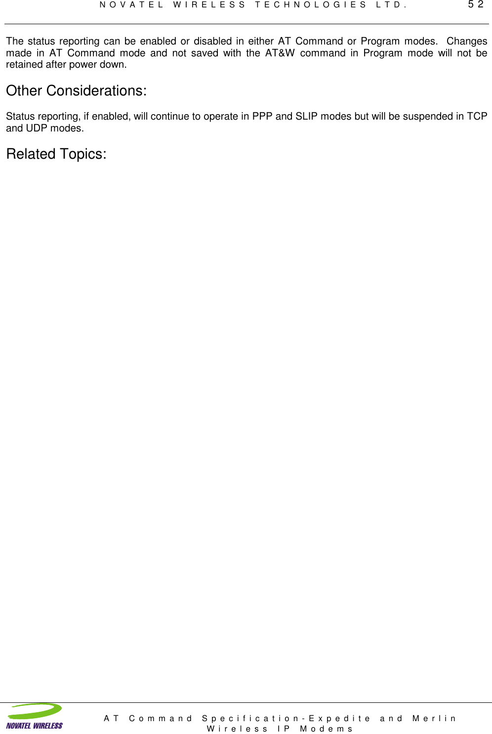
![NOVATEL WIRELESS TECHNOLOGIES LTD. 15AT Command Specification-Expedite and MerlinWireless IP ModemsPush TechnologyTo receive data while the modem is unattended by the host, the modem has been incorporated with themeans to receive the data packet, determine the type of message and the source IP address. This pushtechnology feature can be enabled or disabled by setting or resetting register S250. The modem cansignal the host that there are messages queued up, waiting to be retrieved by the host, using any or all ofthe following signals. The “message waiting” signal can be asserted when a message arrives and will bede-asserted when all messages have been retrieved or deleted. In the case of multiple messages, the“message waiting” signal will be asserted when the first arrives and will only be de-asserted when allmessages have been retrieved. Another signal, the “alert” signal, can also be used to provide a 500msecpulse to the host on its associated pin for each message that arrives. These signals can be madeavailable on any of the programmable pins of the interface. Their assignment is made using theprogrammable GPIO features of the Expedite Wireless IP Modem.The modem can hold up to 4 messages, determined by reading register S251, before the buffer overflowsand message data is lost. When the host accesses the modem to retrieve the stored messages, the hostfirst determines which messages it wants to retrieve based upon the source IP address. The host candiscard messages by setting register S254. This will cause the current message to be flushed from thequeue and the next message made available to the host.PUSH Technology EnableATS250? Query Wake Up Protocol StateATS250=1 Enable Push TechnologyATS250=0 Disable Push TechnologyATS251? Query Number of Pending MessagesResponse [0..4]ATS252? Query First Push MessageResponse [IPaddress/port]Format nnn.nnn.nnn.nnn/xxxxxATS253? Query Type of First Push MessageResponse [0, 1] 0 indicates UDP, 1 indicates TCPATS254=1 Discard Current Message](https://usermanual.wiki/Novatel-Wireless/NRM-3800.Another-Manual/User-Guide-80601-Page-15.png)

![NOVATEL WIRELESS TECHNOLOGIES LTD. 40AT Command Specification-Expedite and MerlinWireless IP ModemsLine Speed and FormatDescription:This command allows the user to specify the data bit rate or “line speed” and format of the host serial portfor all subsequent communications. Some applications have the need for operating at a different linespeed, other than 9600, because of existing or established wire-line software. The line speed change willnot take effect until the registers have been saved and the modem reset.Format:ATS23? To determine the current line settingORAT&L? To determine the current line settingATS23=<S>,<D><P><N> To change the serial port settingsORAT&L<S>,<D><P><N> To change the serial port settingsWhere: <S> = Baud rate in bits/second: [1200 | 2400 | 4800 | 9600 | 19200]<D> = Number of data bits [7 | 8]<P> = Parity [O | E | N]<N> = Number of stop bits [1 | 2]Examples (all have 8 bits, no parity, 1 stop bit)For 19200 enter AT&L19200,8N1For 9600 enter AT&L9600,8N1For 4800 enter AT&L4800,8N1For 2400 enter AT&L2400,8N1For 1200 enter AT&L1200,8N1Default Setting 9600,8N1Note:When AT&L is entered the modem will interpret this as AT&L1200,7O1 (7 bits, odd parity, 1 stop)Validity:This command is valid only in Program Mode. Serial port change will not occur until settings are savedand a soft reset occurs.Other Considerations:The NRM does not support the auto-baud detection function. Characters received with parity errors areignored by the NRM with no indication to the Host.](https://usermanual.wiki/Novatel-Wireless/NRM-3800.Another-Manual/User-Guide-80601-Page-40.png)

![NOVATEL WIRELESS TECHNOLOGIES LTD. 44AT Command Specification-Expedite and MerlinWireless IP ModemsDestination IP Address/PortDescription:This command is used to store the default IP address for the remote host. When the modem is directedto establish a session using TCP, or send UDP packets, without specifying an IP address, the IP addressspecified by register S53 is used at the destination IP. The addition of a preceding “T” or “P” is used todefine a default mode of operation when one is not supplied with the ATD command. The ‘port value’ isthe TCP/UDP port number used to identify the application in the remote host to be used for theconnection-oriented service.Format:ATS53? Query destination IP Addr /PortATS53=T1.2.3.4/1 Set the destination IP Addr/PortWhere: <mode> = Optional access mode for remote hostT = TCP (default).P = UDP<address> = IP address: xxx.xxx.xxx.xxx<port> = TCP/UDP port number [1 - 65535]Example ATS53=166.140.73.2/2100IP = 166.140.73.2Port = 2100Validity:Valid in either AT Command or Program modes. The value specified is stored immediately in NVM.Other Considerations:If set to a non- zero string, this port number is attached to all transmitted packets in UDP-Data mode.Related Topics:TCP mode, UDP mode, Default mode,](https://usermanual.wiki/Novatel-Wireless/NRM-3800.Another-Manual/User-Guide-80601-Page-44.png)
![NOVATEL WIRELESS TECHNOLOGIES LTD. 47AT Command Specification-Expedite and MerlinWireless IP ModemsConnection Establishment Time-outDescription:When initiating a session request as a remote client, attempting to talk to a server, a time-out limit forestablishing the connection can be specified by setting register S7 to the appropriate value. When a TCPsession request is sent out by the modem, the server being called will respond with either an acceptanceor busy message. If the server does so before the time-out limit is reached, the modem will respond withthe acceptance string “CONNECT” or the declining string “BUSY. The server will usually return a “BUSY”message when it is overloaded and cannot accept further sessions. If the server being called does notrespond in the time allowed, the modem will respond with an ERROR message to indicate that it could notestablish a session.Format:ATS7? Connection Timeout valueGeneral Command format ATS7=<time-out>Where: <time-out> = time-out value in seconds [0 - 255]Default 60 secondsExample command ATS7=45 programs a value of 45 seconds for the time-outvalue.Validity:This command is valid only in Program mode. The value must be saved with the AT&W command.Other Considerations:Related Topics:](https://usermanual.wiki/Novatel-Wireless/NRM-3800.Another-Manual/User-Guide-80601-Page-47.png)
![NOVATEL WIRELESS TECHNOLOGIES LTD. 48AT Command Specification-Expedite and MerlinWireless IP ModemsData Forwarding Idle Time-outDescription:When using the internal stack either UDP or TCP, the data being sent to the modem is automaticallyencapsulated in an IP packet using the preset protocol. The packet size may vary depending upon therate at which the data characters are received. If the data is received in a very sporadic manner, themodem will assemble and send a packet after an idle period has elapsed, no data is received in thisinterval. This keeps the data moving, retaining some time relevance instead of waiting for a specificnumber or a full buffer. The modem will also send a packet if a return character is encountered in thedata stream.The timer value is programmable from 0.1 to 25.5 seconds in 1/10th of a second resolution.Format:ATS50? Data Forwarding Idle Time-outGeneral command format ATS50=<time-out value>Where: <time-out value> = Time-out value in 1/10th seconds [0 -255]Example command ATS50=15 the time out value is set to 1.5 secondsDefault factory setting is 0.5 secondsValidity:Other Considerations:For most applications, data is sent in bursts, with each burst of data having relevance within theapplication. To define the length of each packet, it is recommended to send the data in bursts followed bya return. Packet length will vary as both UDP and TCP include overhead information in each packet.Typically TCP will include a 40 byte header while UDP uses less than 20 bytes for header information.UDP is generally used to reduce data transmission costs but requires the application to handle lostpackets and retries.Related Topics:](https://usermanual.wiki/Novatel-Wireless/NRM-3800.Another-Manual/User-Guide-80601-Page-48.png)
![NOVATEL WIRELESS TECHNOLOGIES LTD. 53AT Command Specification-Expedite and MerlinWireless IP ModemsLocal IP Address/PortDescription:Since the modem connects directly to the Internet, it needs to have an IP address to define where datadestined for it can be sent. The two methods for defining IP addresses are static and dynamic. DynamicIP addresses are assigned to the modem each time the modem connects to the network. Dynamic IPaddressing poses several disadvantages with messaging services. These difficulties are overcome withStatic IP addressing which is used by the Expedite Wireless IP Modem. Register S110 is reserved forspecifying the IP address for the NRM. The optional ‘port extension’ is the TCP/UDP port number used tofurther identify the Host application for the connection-oriented service.5The IP address must be specified before the modem can register with the network. Please contact yournetwork provider to receive your IP address. This number is assigned to the modem and must remainunique; you cannot load the same IP address into more than one modem and have them work. The IPaddress cannot be ported or transferred to another modem without alerting your issuing carrier of thechange and the associated Electronic Identifier (EID) numbers of the modems.Once registered on the Network, the EID and IP must remain in the same modem until the Network is toldto “Trust enable” the modem or “Reset Authentication Parameters” for the modem. During initialregistration of the modem, first time registration, the typical process has the Network accepting themodem’s EID without checking it and henceforth using that value along with the IP and authenticationkeys. This will remain in effect until the Network administrator is instructed to change the IP, EID or resetthe credentials.Format:ATS110? IP Address and PortATS110=<Address>/<port> To set the IP addressWhere: <address> = IP address: xxx.xxx.xxx.xxx<port> = TCP/UDP port number [1 - 65535]Example command ATS110=207.107.0.35/2014IP address is 207.107.0.35Port number is 2014This port number is used for “listening” in UDP-Data mode.Validity:The IP address can only be changed in Program mode.Other Considerations:An IP address consists of 4 numbers, 0 to 255, separated by dots (periods). For IP addresses thatcontain zero as one of the numbers, you must enter the zero as part of the IP address as shown in theexample above. An IP address must have four numbers to be valid. Numbers must be limited to 0 to 255in value. Check with your carrier before making any changes to your IP address setting. 5 This address/port combination is used when the NRM opens the TCP port for listening.](https://usermanual.wiki/Novatel-Wireless/NRM-3800.Another-Manual/User-Guide-80601-Page-53.png)

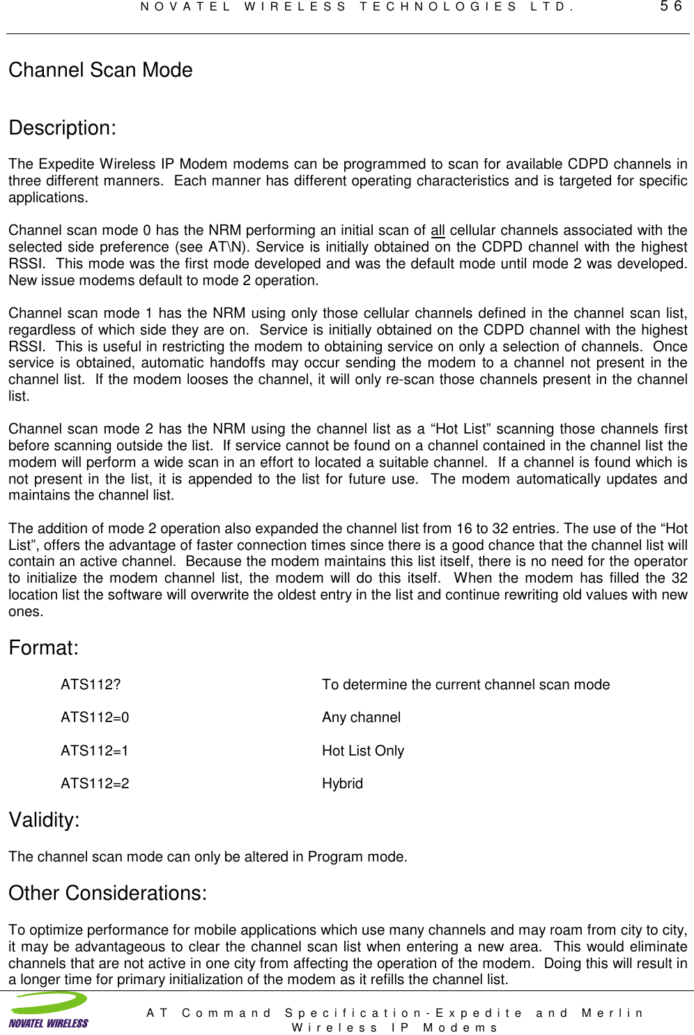

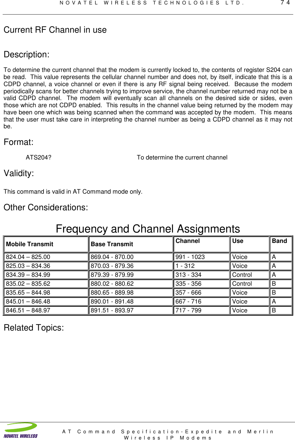
![NOVATEL WIRELESS TECHNOLOGIES LTD. 58AT Command Specification-Expedite and MerlinWireless IP ModemsChannel ListDescription:Register S113 is used to contain the channel list. This is the list of cellular channels on which the NRMmay use to search for CDPD service, depending on the setting of S112. Up to 32 channel numbers maybe entered. If no channel numbers are entered, the NRM will scan the entire CDPD channel setassociated with the side preference.Format:ATS113? Channel List queryATS113=<chan1>,<chan2>,etc. Set channel listWhere: <chan1-32> = All valid CDPD channels [1-799, 991-1023]To zero the channel list ATS113=No value is enteredValidity:The channel scan list can only be altered in Program mode.Other Considerations:A channel number of zero is not valid.Related Topics:](https://usermanual.wiki/Novatel-Wireless/NRM-3800.Another-Manual/User-Guide-80601-Page-58.png)
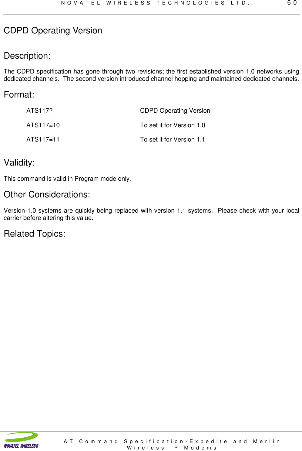
![NOVATEL WIRELESS TECHNOLOGIES LTD. 65AT Command Specification-Expedite and MerlinWireless IP ModemsTCP TimerDescription:When using TCP, a session is initiated by one party calling and the other party accepting or declining thesession request. Once a session is established, the two parties listen only to one another (unless multiplesessions are permitted). After a session is completed and both parties want to disengage, a session teardown message is sent from one to the other. Both parties tear down the stack and are then available toset up another session with someone else. In the event that a tear down message is not received by amodem, an idle timer is available which will tear down the session after a predetermined interval ofinactivity by either party. The values setting for this timer is specified in the TCP Timer register, TCPT.Format:ATTCPT? Query TCP Timer settingATTCPT=value [ 0 to 255 minutes] To set the timer value (minutes)ATTCPT=0 To disable the timerValidity:Other Considerations:A setting of 0 indicates the timer is not used. The minimum setting is 1 minute. It should be noted thatwhen using a sleep mode modem, care should be taken in the selection of an appropriate value, as sleepintervals may create a longer interval of inactivity.Related Topics:](https://usermanual.wiki/Novatel-Wireless/NRM-3800.Another-Manual/User-Guide-80601-Page-65.png)

![NOVATEL WIRELESS TECHNOLOGIES LTD. 73AT Command Specification-Expedite and MerlinWireless IP ModemsQuery Current Block Error Rate (BLER)Description:The modem maintains statistics on its performance and operation. One of the parameters measured andmaintained is the block error rate. This measurement is derived by examining the Reed Solomonalgorithm, that part of the modem’s software that can detect and correct errors in the data stream. Dataerrors that cannot be corrected result in a re-transmission of the bad segment while errors that can becorrected do not result in data re-transmissions. The modem measures the errors and, based upon anerror rate threshold, then uses this measurement to decide when to change channels. The block errorrate can rise to 3% before the effect becomes noticeable by the user. The block error rate is updatedapproximately every second or two when the modem is connected to the network.Format:ATS203? To determine the current Block Error RateThe response will be in the form of a percentage [ 0 to 100%]Validity:This command is valid for AT Command mode. For use in data modes, the MSCI protocol is preferred.Other Considerations:Related Topics:](https://usermanual.wiki/Novatel-Wireless/NRM-3800.Another-Manual/User-Guide-80601-Page-73.png)
![NOVATEL WIRELESS TECHNOLOGIES LTD. 75AT Command Specification-Expedite and MerlinWireless IP ModemsCell Site ID in UseDescription:The CDPD Network is composed of a multitude of cellular towers transmitting their signals over a portionof the total coverage area. By reusing frequencies, a greater density of coverage can be maintained andmore calls supported. To make each tower identifiable to remote terminals (modems), an identifying IDnumber is sent in the forward data stream. This number, [0 to 65535] is useful in reporting problems tothe cellular carrier when the cellular signal is in question.Format:ATS205? To determine the current Cellular IDValidity:This command is valid in AT Command mode only.Other Considerations:Related Topics:](https://usermanual.wiki/Novatel-Wireless/NRM-3800.Another-Manual/User-Guide-80601-Page-75.png)

![NOVATEL WIRELESS TECHNOLOGIES LTD. 81AT Command Specification-Expedite and MerlinWireless IP ModemsDial (Connection Setup)Description:In wire-line modems a connection s made when the modem is instructed to dial a telephone number forthe desired computer service. This dial command ATD provides the user with the means of using eithertone dialing, ATDT, or pulse dialing, ATDP. For wireless Internet modems using CDPD technology, theATD command is used to initiate a session with a remote Internet server using either TCP/IP or UDP.Instead of a phone number, an IP address is used instead. It is here that the use of the Internet makesCDPD easy to use as there are no area codes, no country codes, no need to access an outside line. AllIP addresses currently use a fixed length series of four numbers separated by dots.The Dial Connection Setup command causes the NRM to establish a connection with the host at thespecified IP address/port. For any fields that are left blank, values are taken from those stored in thedefault destination register. The NRM will not process this command if the DTR line is not asserted (i.e.an ERROR response is issued). It is recommended that the host application make sure the modem isconnected to the network before issuing a Dial command.Format:ATDT<IPaddress>/<port#> To initiate a TCP SessionATDP<IPaddress>/<port#> To initiate a UDP ConnectionATDN<Ipaddress> To initiate a Telnet Session. Port 23 is assumed.ATD To use the Default RegisterIPaddress format XXX.XXX.XXX.XXXwhere XXX is a number [0 to 255]port# format XXXXXwhere XXXXX is a number [0 to 65535]ExamplesTCP Connect ATDT166.1.109.3 (no port given, 0 assumed)IP = 166.1.109.3Port = 0UDP Connect ATDP166.1.109.3/55000 (Port number specified)IP = 166.1.109.3Port = 55000Default Connection ADT (S53=P166.1.109.3/55000)Same effect as aboveValidity:This command is valid for AT Command mode only.](https://usermanual.wiki/Novatel-Wireless/NRM-3800.Another-Manual/User-Guide-80601-Page-81.png)

![NOVATEL WIRELESS TECHNOLOGIES LTD. 86AT Command Specification-Expedite and MerlinWireless IP ModemsPing CommandDescription:The Ping command causes the modem to transmit a single ICMP packet of the specified size to theICMP/PING entity of the specified address. The data sent is a simple random pattern that the targeteddestination will return in the same format as it was sent. If the packet is returned, then the path from themodem to the destination address location is intact. If the message is not returned then the path may notbe intact or the destination address may not be able to respond. The Ping command is a very useful toolin trouble shooting problems and confirming the modems operation.Upon issuing the Ping command the modem will send the ICMP Ping message to the destination address.The modem will wait for a return message. If the destination address returns the Ping message before 20seconds has elapsed, an OK result code is emitted. If the Ping message is not returned in less than 20seconds, an ERROR result code is emitted. Additional PING commands must not be issued if a PINGcommand is already in progress, you must wait for either the OK or the ERROR response.The ping command can be used to send messages up to 128 bytes in length by adding a forward slashand a number, 1 to 128, afterwards. If no forward slash is included the Ping message will be 32 bytes inlength.Format:ATPING<XXX.XXX.XXX.XXX>/<Length> To send a ICMP Ping messageIPaddress format XXX.XXX.XXX.XXXwhere XXX is a number [0 to 255]Length value range [1 to 128]Validity:Other Considerations:In earlier versions of the modem software a BUSY result code was emitted upon transmitting the ICMPPing message. There is currently no trace route function within the modem. This function is resident inWindows 95 and can be run using PPP or SLIP and the external stack.Related Topics:](https://usermanual.wiki/Novatel-Wireless/NRM-3800.Another-Manual/User-Guide-80601-Page-86.png)


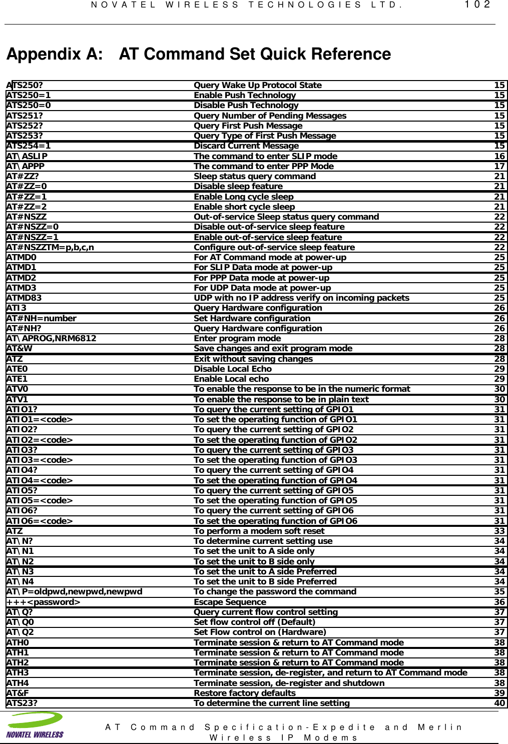
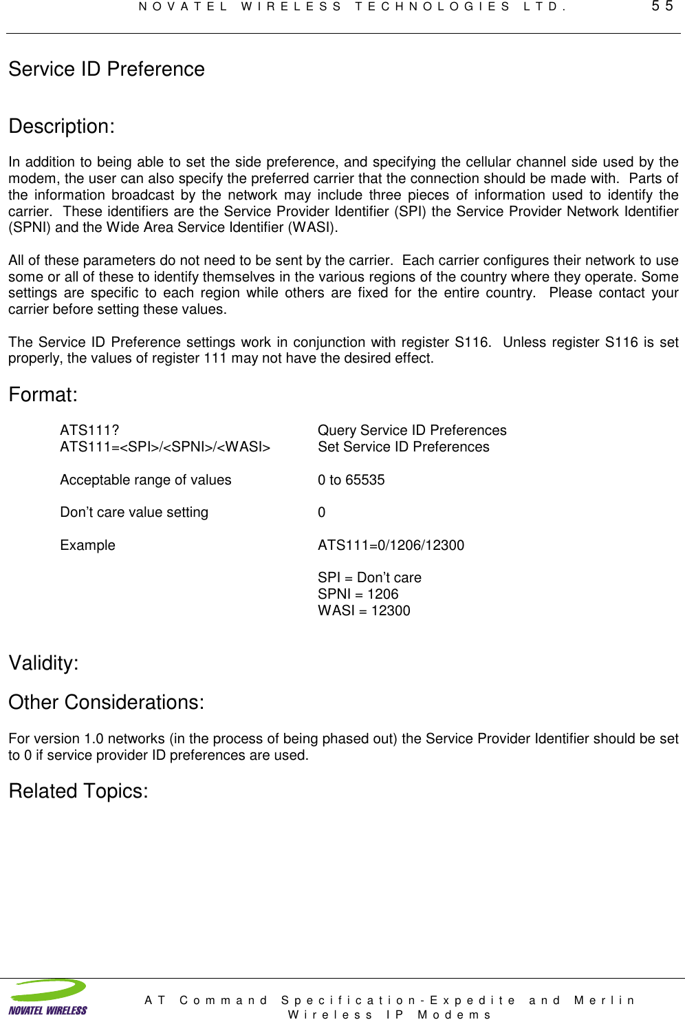
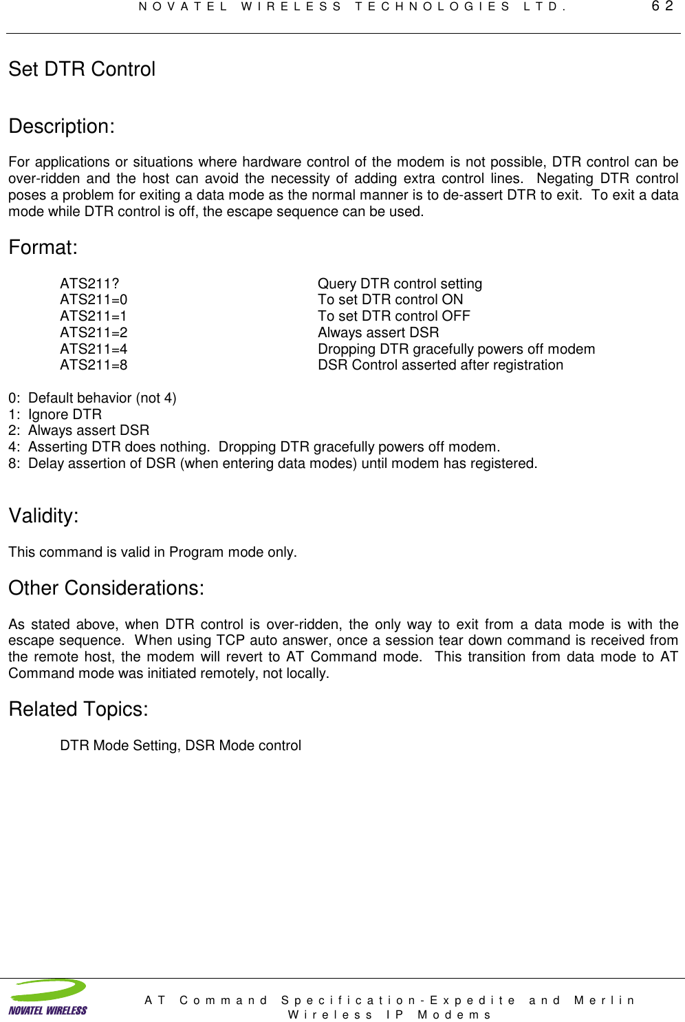
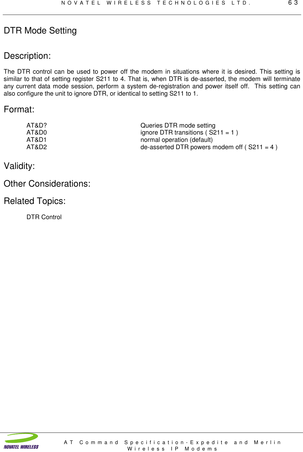
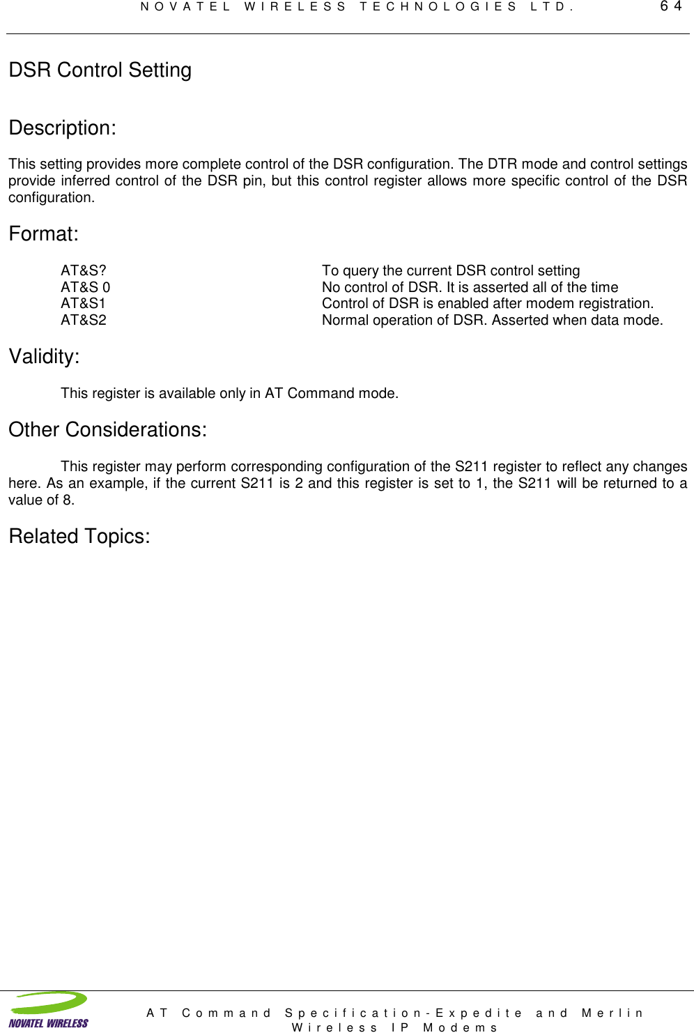
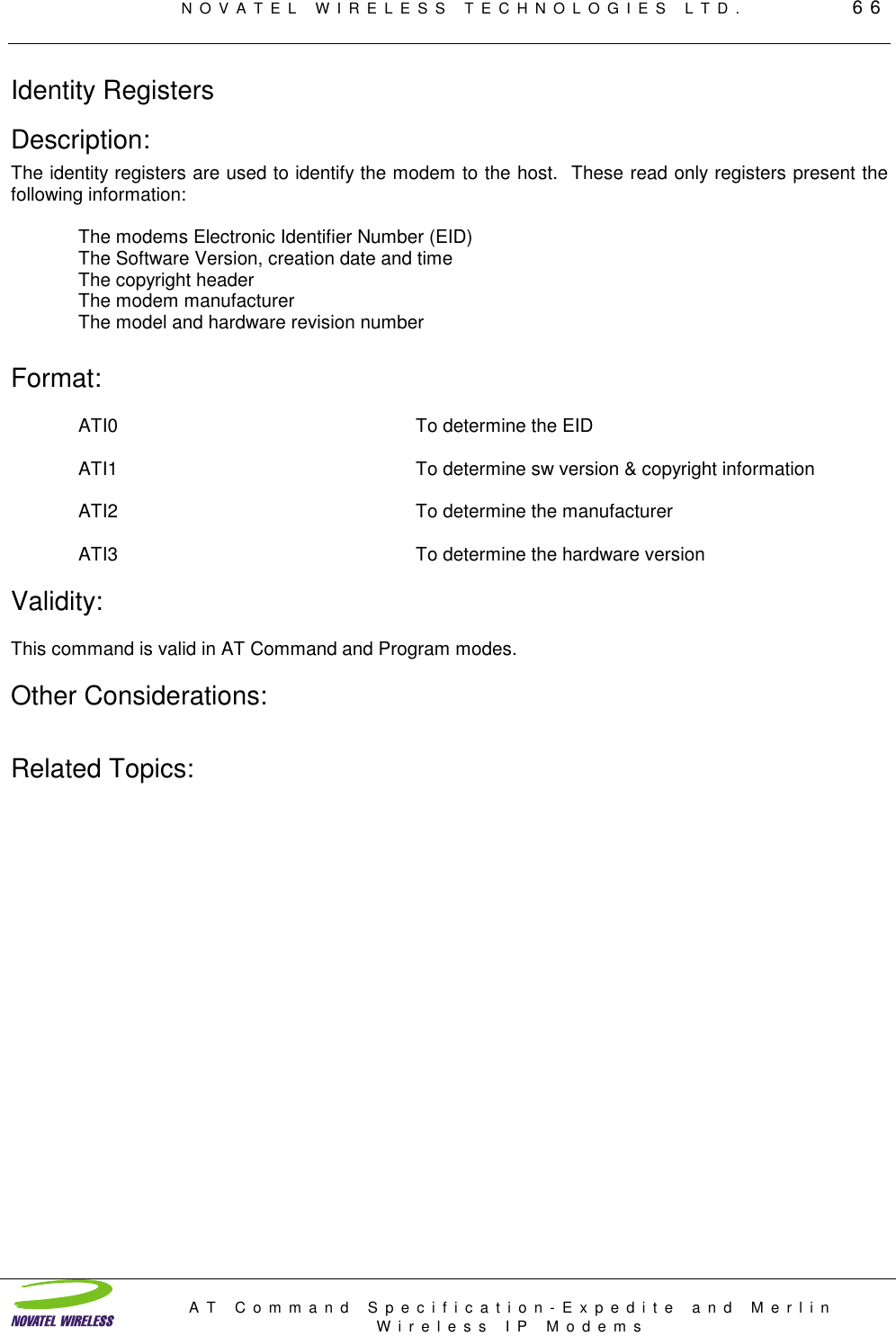
![NOVATEL WIRELESS TECHNOLOGIES LTD. 103AT Command Specification-Expedite and MerlinWireless IP ModemsAT&L? To determine the current line setting 40ATS23=<S>,<D><P><N> To change the serial port settings 40AT&L<S>,<D><P><N> To change the serial port settings 40AT&V View active profile 42AT&W Save changes 43ATS53? Query destination IP Addr /Port 44ATS53=T1.2.3.4/1 Set the destination IP Addr/Port 44AT#X=1 Enter debug mode 45AT#X=0 Exit debug mode 45ATS0? Auto Answer Query 46ATS0=1 Set Auto Answer mode ON 46ATS0=0 Set Auto Answer mode OFF 46ATS7? Connection Timeout value 47ATS50? Data Forwarding Idle Time-out 48ATS51? Query Data Forwarding Idle Character 49ATS51=0 Disabled Data Forwarding Idle Character 49ASS51=aa Data Forwarding Idle Character values of 1-255 49ATS82=0 regular mode 50ATS82=1 not used (reserved) 50ATS82=2 Half-Open mode enabled 50ATS83? Query UDP Open Timeout 50ATS83=60 Set UDP Open Timeout 50ATS103? To determine the current setting 51ATS103=1 To enable status reporting 51ATS103=0 To disable status reporting 51ATS110? IP Address and Port 53ATS110=<Address>/<port> To set the IP address 53ATS111? Query Service ID Preferences 55ATS111=<SPI>/<SPNI>/<WASI> Set Service ID Preferences 55ATS112? To determine the current channel scan mode 56ATS112=0 Any channel 56ATS112=1 Hot List Only 56ATS112=2 Hybrid 56ATS113? Channel List query 58ATS113=<chan1>,<chan2>,etc. Set channel list 58ATS116? Query Service ID preference 59ATS116=0 To only use S111 service ID 59ATS116=1 To prefer S111 service ID 59ATS116=2 To not use S111 service ID 59ATS116=3 To use any service ID 59ATS117? CDPD Operating Version 60ATS117=10 To set it for Version 1.0 60ATS117=11 To set it for Version 1.1 60ATS210? Query Wireline Compatibility setting 61ATS210=0 To enable the line feed character 61ATS210=1 To suppress the line feed character 61ATS211? Query DTR control setting 62ATS211=0 To set DTR control ON 62ATS211=1 To set DTR control OFF 62ATS211=2 Always assert DSR 62ATS211=4 Dropping DTR gracefully powers off modem 62ATS211=8 DSR Control asserted after registration 62AT&D? Queries DTR mode setting 63AT&D0 ignore DTR transitions ( S211 = 1 ) 63AT&D1 normal operation (default) 63AT&D2 de-asserted DTR powers modem off ( S211 = 4 ) 63AT&S? To query the current DSR control setting 64AT&S 0 No control of DSR. It is asserted all of the time 64AT&S1 Control of DSR is enabled after modem registration. 64AT&S2 Normal operation of DSR. Asserted when data mode. 64ATTCPT? Query TCP Timer setting 65ATTCPT=value [ 0 to 255 minutes] To set the timer value (minutes) 65ATTCPT=0 To disable the timer 65ATI0 To determine the EID 66ATI1 To determine sw version & copyright information 66ATI2 To determine the manufacturer 66](https://usermanual.wiki/Novatel-Wireless/NRM-3800.Another-Manual/User-Guide-80601-Page-103.png)