Novatel Wireless NRM-3800 CDPD Data Transceiver User Manual Vespa AT Command Set Reference Guide 0 1
Novatel Wireless, Inc. CDPD Data Transceiver Vespa AT Command Set Reference Guide 0 1
Contents
- 1. Manual
- 2. Another Manual
- 3. Revised Manual Page 13
- 4. Manual Changes
Another Manual
AT Command Set
Reference Guide
for
Expedite and Merlin
Wireless IP Modems
PS-01016529
UNRELEASED
Release 2.1
Friday, May 7, 1999
The information disclosed herein is the exclusive property of NOVATEL WIRELESS TECHNOLOGIES
LTD. and is not to be disclosed without the written consent of NOVATEL WIRELESS TECHNOLOGIES
LTD. No part of this publication may be reproduced or transmitted in any form or by any means including
electronic storage, reproduction, execution or transmission without the prior written consent of NOVATEL
WIRELESS TECHNOLOGIES LTD. The recipient of this document, by its retention and use, agrees to
respect the security status of the information contained herein.
This document is intended for limited circulation.
The information contained in this document is subject to change without notice and should not be
construed as a commitment by NOVATEL WIRELESS TECHNOLOGIES LTD. unless such commitment
is expressly given in a covering document.
© Copyright NOVATEL WIRELESS TECHNOLOGIES LTD. (1999)

REVISION HISTORY
REV# ECO# EFF. DATE DESCRIPTION PREPARED APPROVED
1 99010 990505 Initial release. D. Barber S. Smilar
2.0 99024 990705 Updated to include new features for
TV01-02, including Friends Mode,
Quiet mode and Stack Check
features.
D. Barber S, Smilar
2.1 Added registration mode and out-of-
service sleep commands. Added
index of AT commands.

NOVATEL WIRELESS TECHNOLOGIES LTD. 4
AT Command Specification-Expedite and Merlin
Wireless IP Modems
Table of Contents
INTRODUCTION.................................................................................................................................................... 6
Scope ....................................................................................................................................................................... 6
PHYSICAL INTERFACE ....................................................................................................................................... 7
Protocol................................................................................................................................................................ 7
Software Interface .................................................................................................................................................. 8
AT Command Mode........................................................................................................................................... 8
Command format................................................................................................................................................ 8
Result format....................................................................................................................................................... 8
Data Mode Description ...................................................................................................................................... 9
Internal Stack Description ............................................................................................................................... 10
UDP Mode Description .................................................................................................................................... 11
TCP Mode Description..................................................................................................................................... 12
DTR Control Description.................................................................................................................................. 14
Push Technology.............................................................................................................................................. 15
Slip Mode........................................................................................................................................................... 16
Point to Point Protocol (PPP).......................................................................................................................... 17
Data Transmission Mode ................................................................................................................................18
Data Reception Mode ...................................................................................................................................... 19
Sleep Mode Description................................................................................................................................... 20
Sleep Mode Feature Enable/Disable ............................................................................................................. 21
Out-of-service Sleep Mode ............................................................................................................................. 22
Power-up Default Mode................................................................................................................................... 25
Set Hardware Configuration............................................................................................................................ 26
Profile Configuration Commands ................................................................................................................... 27
Program Mode .................................................................................................................................................. 28
Local Echo......................................................................................................................................................... 29
Response Format............................................................................................................................................. 30
Programmable I/O............................................................................................................................................ 31
Soft Reset.......................................................................................................................................................... 33
Side Preference................................................................................................................................................ 34
Password........................................................................................................................................................... 35
Escape Sequence ............................................................................................................................................ 36
Hardware Flow Control.................................................................................................................................... 37
Disconnect (Hang-up)...................................................................................................................................... 38
Restore Factory Defaults................................................................................................................................. 39
Line Speed and Format................................................................................................................................... 40
View Active Profile............................................................................................................................................ 42
Save Current Profile......................................................................................................................................... 43
Destination IP Address/Port............................................................................................................................ 44
Debug Mode...................................................................................................................................................... 45
Auto Answer (TCP Listen)............................................................................................................................... 46
Connection Establishment Time-out.............................................................................................................. 47
Data Forwarding Idle Time-out....................................................................................................................... 48
Data Forwarding Idle Character ..................................................................................................................... 49
UDP Half Open Mode ...................................................................................................................................... 50
Status Reporting............................................................................................................................................... 51
Local IP Address/Port ...................................................................................................................................... 53
Service ID Preference...................................................................................................................................... 55
Channel Scan Mode......................................................................................................................................... 56
Channel List ...................................................................................................................................................... 58

NOVATEL WIRELESS TECHNOLOGIES LTD. 5
AT Command Specification-Expedite and Merlin
Wireless IP Modems
Service ID Preference...................................................................................................................................... 59
CDPD Operating Version ................................................................................................................................60
Wireline Compatibility ...................................................................................................................................... 61
Set DTR Control ............................................................................................................................................... 62
DTR Mode Setting............................................................................................................................................ 63
DSR Control Setting......................................................................................................................................... 64
TCP Timer......................................................................................................................................................... 65
Identity Registers.............................................................................................................................................. 66
Description:........................................................................................................................................................ 66
Query Network Connection Status................................................................................................................. 67
Last network registration error code .............................................................................................................. 70
Authentication Parameter................................................................................................................................71
Query Current RSSI Value.............................................................................................................................. 72
Query Current Block Error Rate (BLER) ....................................................................................................... 73
Current RF Channel in use ............................................................................................................................. 74
Cell Site ID in Use ............................................................................................................................................ 75
Area Color Code in Use................................................................................................................................... 76
Power Level Query........................................................................................................................................... 77
Symbol Error Rate Query................................................................................................................................78
Power Product................................................................................................................................................... 79
Authentication Failures Query......................................................................................................................... 80
Dial (Connection Setup)................................................................................................................................... 81
ADC Monitoring................................................................................................................................................. 83
Ping Command................................................................................................................................................. 86
Power Boost...................................................................................................................................................... 87
Message Waiting.............................................................................................................................................. 88
Internal MRU Setting........................................................................................................................................ 89
TCP Suspension Enable ................................................................................................................................. 90
Call Progress Result Mode ............................................................................................................................. 91
Answer ............................................................................................................................................................... 92
Telnet Echo ....................................................................................................................................................... 93
Modem Identification........................................................................................................................................ 94
Friends Mode .................................................................................................................................................... 95
Stack Check ...................................................................................................................................................... 97
Quiet Mode........................................................................................................................................................ 98
Registration Mode ............................................................................................................................................ 99
Fixed Parameters........................................................................................................................................... 100
Unsupported Commands .............................................................................................................................. 101
Unsupported Functions.................................................................................................................................. 101
Appendix A: AT Command Set Quick Reference....................................................................................... 102
Index of AT Commands..................................................................................................................................... 106

NOVATEL WIRELESS TECHNOLOGIES LTD. 6
AT Command Specification-Expedite and Merlin
Wireless IP Modems
INTRODUCTION
This document is intended to provide the serial AT Command Interface provided by Expedite
Wireless IP Modem for embedded OEM applications. The Expedite Wireless IP modem provides
a connection-oriented service so that existing OEM application protocols can be used. In addition,
the capability to switch the unit to Serial-Line-Internet-Protocol (SLIP) or Point-to-Point-Protocol
(PPP) modes are provided so that new protocols can be developed within the OEM application.
This document describes the Novatel Wireless Expedite Wireless IP Modem. The Expedite
Wireless IP modem is an OEM-module designed for integration into a host product to provide
wireless data communication capability via the CDPD (Cellular Digital Packet Data) Network. It
features internal TCP and UDP IP stacks as well as SLIP and PPP protocols for an external stack
and provisions for using “Sleep Mode” to extend the operating time of battery powered devices.
Scope
The scope of this document is limited to providing information on the various AT commands which
can be used on Novatel CDPD products as well as a brief summary of some of the standard AT
commands which are not supported. Internal design issues, detailed operating instructions and
cost information is not included in this document.
NOVATEL WIRELESS TECHNOLOGIES LTD. 7
AT Command Specification-Expedite and Merlin
Wireless IP Modems
PHYSICAL INTERFACE
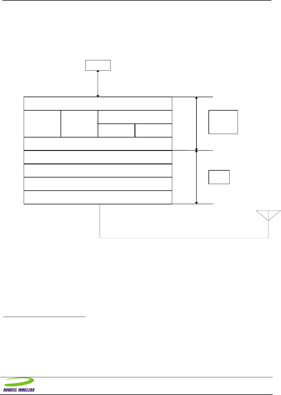
Protocol
CDPD System Specification Part 400 Version 1.1 (CDPD Forum Inc.) This is the protocol stack
for the Expedite Wireless IP Modem:
Ph
y
sical
MAC
MDLP
SNDCP
IP
SLIP PPP UDP TCP
AT Interface
Communication Driver
CDPD
La
y
ers
Host
OEM
A
pp
lication
La
y
ers
To Host
The Expedite Wireless IP Modem does not support V.42 compression in SNDCP.
The TCP/UDP interface is capable of supporting up to 3 sessions simultaneously1.
The AT-command set described herein is derived from “CDPD Implementor Guidelines”, Release 1.12. It
contains a subset of the commands described in Part 2014 that are supported by the Novatel Expedite
Wireless IP Modem.
For the purposes of this specification, “NRM” refers to the Novatel Expedite Wireless IP Modem; “Host”
refers to the OEM application controller.
1 This is provided to solve the problem presented by delays encountered when closing a TCP session. That is, in order to process
Host transactions in rapid succession (and since it is required to establish a new TCP session for each transaction) it is
necessary to establish a new TCP session before the previous one has had a chance to close.
2 CDPD Forum makes no representations about the suitability of any material, comprising the CDPD system specification (or any
derivative work incorporating any element thereof) for any purpose; it being provided “as is” and without any warranties
whatsoever, express or implied. The CDPD Forum shall not be responsible for any damages of any kind related to the use of
the CDPD system specification (or any derivative work incorporating any element thereof), including without limitation,
actual, direct, indirect, incidental, consequential, special, or general damages.

NOVATEL WIRELESS TECHNOLOGIES LTD. 8
AT Command Specification-Expedite and Merlin
Wireless IP Modems
Software Interface
A brief description of those functions specific to the Expedite Wireless IP Modem is described here.
AT Command Mode
AT commands and responses are active in command mode only; as determined by the state of the DSR
line. Command mode behavior conforms to ANSI/TIA/EIA-602-1992 section 5, with the limitations stated
below. The AT command set is a subset of the AT command set defined in ANSI/TIA/EIA-602 and in the
CDPD System Specification Part 2014 Version 1.1, section 4.
Command format
Note the following limitations:
- The termination character is fixed as CR (ASCII 13).
- Command line editing is supported (BS, ASCII 08 only).
- Command line repeats (A/) is not supported.
- The rules described below for buffering and flow control also apply to command mode. The Host
should not transmit a single AT command which exceeds the buffer length (256 characters). In
addition, the Host should wait until all responses associated with an AT command string have been
received before issuing another AT command.
- Abortion of command-in-progress is not supported.
- Default command parameters are accepted for the last command on a command line only.
Result format
The format of result code responses is determined by the ATV command setting.
In terse mode, the result code is sent as a single ASCII character followed by a carriage return (ASCII 13)
character.
In verbose mode, a descriptive text message is sent followed by a carriage return. The following result
codes are emitted by the NRM:
Terse
mode Verbose mode Description of Command
0 OK Command accepted.
1 CONNECT Connection established.
2 RING Network origination indication.
3 NO CARRIER Connection terminated, not established or command aborted.
4 ERROR Invalid command parameter/state (e.g. DTR must be active before ATD can be
accepted.)
5 NO SOCKETS No free TCP sockets within S7 seconds.
6 NO DIALTONE CDPD link not established.
7 BUSY Refused by destination or network, OR: Operation in progress.
8 NO ANSWER No response received from the destination within S7 seconds.
9 HELLO Issued at power on/reset.

NOVATEL WIRELESS TECHNOLOGIES LTD. 9
AT Command Specification-Expedite and Merlin
Wireless IP Modems
Data Mode Description
The modem contains an integrated TCP/IP protocol stack. It is accessed via AT commands that put the
modem into either a TCP or UDP data communications mode. If the application host contains a TCP/IP
stack, PPP or SLIP can be used to transfer IP packets between the application host and the modem.
The Data Terminal Ready (DTR) line is used by the modem as a qualifier for its operation in a data mode,
TCP, UDP, SLIP or PPP. The DTR line is to be asserted before entering a data mode to indicate to the
modem that the host computer is available for operation. The DTR line is de-asserted to terminate a data
session. The modem will not sustain a data mode session without DTR being active. The use of DTR
can be overridden by setting register S211 to 1: the equivalent of asserting DTR permanently.
The DSR Signal is driven by the modem to indicate the existence of a data session. When the local host
asserts DTR, the modem will respond with the DSR signal to indicate that the modem has entered data
mode. DSR is de-asserted to indicate that the modem has exited data mode.
The NRM provides Host and Network originated access to the connection-oriented service using TCP/IP.
Host origination is accomplished via the DIAL (ATDT) command. Upon successful completion of the DIAL
command (i.e. CONNECT result code), the NRM switches to TCP-Data mode. DTR must be asserted
prior to issuing the ATDT, ATDP, AT\ASLIP or AT\APPP. If this is not followed the modem will not engage
the session in a manner where it can be sustained. The NRM signals a network origination to the Host
using the RING result code. Failure to have DTR asserted while in “Listen” mode, network origination, will
result in a dropped session. The PAD functions are active during TCP-Data mode only, however, the
data buffering functions apply in all modes.
For Listen mode applications, the modem must see DTR asserted when the TCP Session request is
received. If DTR is not asserted the session request will be rejected. When the DTR signal is asserted,
the modem will issue a RING followed by a CONNECT to indicate the beginning of an incoming data
session. Here RING indicates the source of the session as being a remote server while the CONNECT
indicates the transition from AT Command mode to Data mode. . In this mode, the NRM will “Listen” for
TCPP packets with port numbers which match that specified with the NRM’s IP address (re: S110). Any
TCP packets received in AT-CDPD mode, or packets received in TCP-Data mode without a matching port
number, are rejected by the NRM with no indication to the Host. DTR can be used to terminate the
session or the remote server can initiate the termination.
A session may be terminated by the Host de-asserting the DTR line. The remote host may also terminate
a session. Connection status is maintained on the DSR line. Once the session has been terminated, the
NRM returns to AT-CDPD mode. Note that session termination is the only method to return to AT-CDPD
mode3.
For UDP/IP, a connection-oriented service is “fabricated” within the NRM. The DIAL command (ATDP) is
used to place the NRM into UDP-Data mode. In this mode, the NRM will “Listen” for UDP packets with
port numbers which match that specified with the NRM’s IP address (re: S110). Any UDP packets
received in AT-CDPD mode, or packets received in UDP-Data mode without a matching port number, are
rejected by the NRM with no indication to the Host. In UDP-Data mode, the port number for transmitted
UDP packets is specified with the destination address associated with the DIAL command. Only the Host
Origination and Host Termination scenarios described above apply to UDP operation. The DTR and DSR
lines, and the PAD functions, operate as in TCP-Data mode.
3 The Hayes compatible escape sequence is not supported.

NOVATEL WIRELESS TECHNOLOGIES LTD. 10
AT Command Specification-Expedite and Merlin
Wireless IP Modems
Internal Stack Description
IP (Internet Protocol) is the basic network protocol that routes packets on an IP network. CDPD networks
and the Internet are IP networks. Transport protocols deliver packets between applications. Transport
protocols use the IP service to deliver data packets between network devices.
In order for an application to communicate across a network, it will first open a port on the local device.
The IP address of the local device and this port number becomes the unique address for this application,
and is sometimes referred to as a socket. When the local application communicates with a distant
application, it will send a packet addressed to the IP address and port number of that remote application.
This address is the destination address of the packet. The packet will also contain the source address, the
IP address and port number of the local application. The remote application may use the source address
of the packet received to communicate back to the local application.
There are two common transport protocols used in TCP/IP networks:

NOVATEL WIRELESS TECHNOLOGIES LTD. 11
AT Command Specification-Expedite and Merlin
Wireless IP Modems
UDP Mode Description
User Datagram Protocol is a basic transport protocol that provides a best-effort, connectionless delivery
service with minimum overhead. The protocol does not guarantee delivery of packets. There is no
checking or retransmission of the data packets. It does provide minimum overhead as it only adds the
source and destination port numbers to the header. Since the protocol is unreliable, the application must
provide checking, acknowledgments and retransmissions if the data is critical. In many applications, the
data is not critical because updates are sent periodically and occasional losses can be tolerated.
UDP sessions may be originated by the local application host or by the network. The DTR signal must be
asserted or S211=1 (pretend DTR is always asserted) for the unit to enter into a data communications
session. The session is terminated by dropping DTR or resetting the unit.
UDP Modes of Operation
Command: ATS82 = <mode>
Where <mode> = Timer value in seconds
0 = Regular mode
1 = Not used (reserved)
2 = Half-Open mode
Originating a UDP Session
A session is originated by the application host issuing the ATD (Dial) command:
ATDPnnn.nnn.nnn.nnn/ppppp
ATDP specifies a UDP session. nnn.nnn.nnn.nnn is the destination IP address and ppppp is the
destination application port number. If no port is specified then a port number of 0 is assumed. It should
be noted that UDP and TCP make extensive use of port numbers, please be aware that the modem will
use the port number as a criteria for accepting and passing data to the host application.
CONNECT [terse 1] result code will be issued and all ensuing data sent from the host application will be
assembled into a UDP packet and transmitted to the destination application.
ERROR [terse 4] result code will be generated if the modem is not currently registered on a CDPD
network.
PAD (Packet Assembly and Disassembly) function will transmit data when the inter-character idle time-out
occurs or when the PAD buffer is full. (256 or 512 bytes). The idle time-out is specified in register S50 in
1/10 seconds.
Receiving Data - Once the session is started, any packets sent to the modem's IP address with the port
number specified in register S110 will be processed and the data portion will be transmitted over the serial
link to the host application. Any packets received with a different port number specified will be discarded.
Termination - The session is terminated by dropping DTR or resetting the unit.

NOVATEL WIRELESS TECHNOLOGIES LTD. 12
AT Command Specification-Expedite and Merlin
Wireless IP Modems
TCP Mode Description
Transport Control Protocol, is a reliable, connection-oriented transport protocol that uses
acknowledgments and retransmissions to guarantee delivery. This is an obvious advantage for
applications where the data is critical and the application cannot provide the required reliability. There is
more overhead in the protocol to provide this reliability, making it less efficient than UDP. For larger data
transfers, TCP is the easiest protocol to use to get reliable service.
TCP sessions may be originated by the local application host or by the network. The DTR signal must be
asserted or S211=1 (pretend DTR is always asserted) for the unit to enter into a data communications
session. The session is terminated by powering the modem off, dropping DTR or by the remote host
terminating the connection. If the session is terminated by a power down, the remote host may not tear
down its part of the session properly, leaving the remote host waiting for further information for that
session. This can pose problems for some applications. Care in session tear down is essential for
reliable operation.
TCP Modes of Operation
TCP Listen mode is established by having S0=1 when the modem powers up. . The port specified in
S110 will be used for the TCP Listen mode. The DTR signal must be asserted or S211=1 (ignore signal on
DTR pin and proceed as if DTR is always asserted) for the unit to enter into a data communications
session. When a connection request for the correct port is received by the modem, the modem will
establish the connection notify the local host with:
Verbose Terse
RING 2
CONNECT 1
and begin the TCP session.
Termination - A TCP connection is terminated by dropping DTR, or by the remote end of the TCP
connection terminating the session.
Originating a TCP Session
A session is originated by the host application by issuing the ATD (Dial) command:
ATDTnnn.nnn.nnn.nnn/ppppp
ATDT specifies a TCP session. nnn.nnn.nnn.nnn is the destination IP address and ppppp is the
destination application port number. The modem will attempt to establish a connection with the destination
host. If it is successful, a CONNECT [terse 1] result code will be issued and all ensuing data sent from the
app host will be assembled into a TCP packet and transmitted to the destination application.
ERROR [terse 4] result code will be generated if the modem is not currently registered on a CDPD
network.
Connection Failure will be signaled by a BUSY [terse 7] result code, and may be caused by one of the
following:
- Wrong IP address or port number
- The destination device does not have a TCP Listen process open on the port specified.
- The destination host already has a connection established with another client on the specified port.

NOVATEL WIRELESS TECHNOLOGIES LTD. 13
AT Command Specification-Expedite and Merlin
Wireless IP Modems
- Connection failed to complete within the time specified in register S7 (sec). Normal values are about
30 seconds, but is very dependent upon the application requirements. Many applications, which
provide their own time-out for connection failure, will have this value set to 60+ seconds.
PAD (Packet Assembly and Disassembly) function will transmit data when the inter-character idle time-out
occurs or when the PAD buffer is full. (256 or 512 bytes). The idle time-out is specified in register S50 in
1/10 seconds.
Receiving Data - Once the session is started, any packets sent to the modem's IP address with the port
number specified in register S110 will be processed and the data portion will be transmitted over the serial
link to the host application. Any packets received with a different port number specified will be discarded.
Termination - A TCP connection is terminated by dropping DTR or by the remote end of the TCP
connection terminating the session.

NOVATEL WIRELESS TECHNOLOGIES LTD. 14
AT Command Specification-Expedite and Merlin
Wireless IP Modems
DTR Control Description
The Data Terminal Ready (DTR) line is used by the modem as a qualifier for its operation in a data mode,
TCP, UDP, SLIP or PPP. The DTR line is to be asserted before entering a data mode to indicate to the
modem that the host computer is available for operation. The DTR line is de-asserted to terminate a data
session. The modem will not sustain a data mode session without DTR being active. The use of DTR
can be overridden by setting register S211 to 1: the equivalent of asserting DTR permanently.
The DSR Signal is driven by the modem to indicate the existence of a data session. When DTR is
asserted by the local host, the modem will respond with the DSR signal to indicate that the modem has
entered data mode. DSR is de-asserted to indicate that the modem has exited data mode.
For Listen mode applications, the modem must see DTR asserted when the TCP Session request is
received. If DTR is not asserted the session request will be rejected. When the DTR signal is asserted,
the modem will issue a RING followed by a CONNECT to indicate the beginning of a incoming data
session. Here RING indicates the source of the session as being a remote server while the CONNECT
indicates the transition from AT Command mode to Data mode. . In this mode, the NRM will “Listen” for
TCPP packets with port numbers which match that specified with the NRM’s IP address (re: S110). Any
TCP packets received in AT-CDPD mode, or packets received in TCP-Data mode without a matching port
number, are rejected by the NRM with no indication to the Host. DTR can be used to terminate the
session or the remote server can initiate the termination.
A session may be terminated by the Host using the DTR line. The remote host may also terminate a
session. Connection status is maintained on the DSR line. Once the session has been terminated, the
NRM returns to AT-CDPD mode. Note that session termination is the only method to return to AT-CDPD
mode4.
The DTR line de-asserted can also be optionally used to power the modem off in addition to the
termination of the session. If the S211 register is set to 4, then the de-asserting of the DTR line will make
the modem terminate any current data session, perform a de-registration with the network and power itself
off.
4 The Hayes compatible escape sequence is not supported.

NOVATEL WIRELESS TECHNOLOGIES LTD. 15
AT Command Specification-Expedite and Merlin
Wireless IP Modems
Push Technology
To receive data while the modem is unattended by the host, the modem has been incorporated with the
means to receive the data packet, determine the type of message and the source IP address. This push
technology feature can be enabled or disabled by setting or resetting register S250. The modem can
signal the host that there are messages queued up, waiting to be retrieved by the host, using any or all of
the following signals. The “message waiting” signal can be asserted when a message arrives and will be
de-asserted when all messages have been retrieved or deleted. In the case of multiple messages, the
“message waiting” signal will be asserted when the first arrives and will only be de-asserted when all
messages have been retrieved. Another signal, the “alert” signal, can also be used to provide a 500msec
pulse to the host on its associated pin for each message that arrives. These signals can be made
available on any of the programmable pins of the interface. Their assignment is made using the
programmable GPIO features of the Expedite Wireless IP Modem.
The modem can hold up to 4 messages, determined by reading register S251, before the buffer overflows
and message data is lost. When the host accesses the modem to retrieve the stored messages, the host
first determines which messages it wants to retrieve based upon the source IP address. The host can
discard messages by setting register S254. This will cause the current message to be flushed from the
queue and the next message made available to the host.
PUSH Technology Enable
ATS250? Query Wake Up Protocol State
ATS250=1 Enable Push Technology
ATS250=0 Disable Push Technology
ATS251? Query Number of Pending Messages
Response [0..4]
ATS252? Query First Push Message
Response [IPaddress/port]
Format nnn.nnn.nnn.nnn/xxxxx
ATS253? Query Type of First Push Message
Response [0, 1] 0 indicates UDP, 1 indicates TCP
ATS254=1 Discard Current Message

NOVATEL WIRELESS TECHNOLOGIES LTD. 16
AT Command Specification-Expedite and Merlin
Wireless IP Modems
Slip Mode
Description:
The command to enter Serial Line Internet Protocol mode (SLIP) is used when an external stack
configuration is needed. SLIP is useful if the stack resides in the host computer, multiple sessions and
complete control over all aspects of each session can be obtained. SLIP is one of the more common
protocols used for splitting the functionality between the modem and the host. SLIP does, however,
require certain parameters to be set up prior to activating a session. SLIP does not extract the IP address
from the modem. This must be set up in dial-up-networking before starting. SLIP is less flexible than
Point to Point Protocol (PPP) which is quickly winning over most users.
The SLIP session is usually controlled by DTR, unless the modem has been configured to ignore DTR by
programming register S211. DTR, when used, must be asserted to initiate a session and de-asserted to
terminate a session. If the modem has been programmed not to use DTR Control, then the command
AT\ASLIP can be sent without asserting DTR. To exit SLIP in this case, the host must either power down
the modem or use the escape sequence. To terminate a SLIP session, DTR must be de-asserted or the
escape sequence can be activated or the modem can be powered down.
Format:
AT\ASLIP The command to enter SLIP mode
Validity:
Slip can only be entered from Command Mode. In Program or Diagnostic modes, the modem is not
actively connected to the network.
Other Considerations:
While a modem can enter SLIP mode from command mode at any time, the intent of SLIP is to connect to
the network. Until there is a network connection established and the modem has registered, it is better to
delay entering SLIP mode as you may report errors that will only persist until the modem registers. It is
generally recommended that the host check the status of the modem before proceeding with a SLIP
connection. The Status can be checked using the “ATS57?” command.
Related Topics:
Enter PPP Mode, DTR Control, Program Mode, Data Mode, Diagnostic Mode. Checking Status, Escape
Sequence

NOVATEL WIRELESS TECHNOLOGIES LTD. 17
AT Command Specification-Expedite and Merlin
Wireless IP Modems
Point to Point Protocol (PPP)
Description:
The command to enter Point to Point Protocol mode (PPP) is used when an external stack configuration is
needed. PPP is useful if the stack resides in the host computer, providing multiple sessions and complete
control over all aspects of each session. PPP is quickly becoming the new standard for dial-in-networking.
PPP provides more flexibility and less items that need to be explicitly set.
The PPP session is usually controlled by DTR, unless the modem has been configured to ignore DTR by
programming register S211. DTR, when used, must be asserted to initiate a session and de-asserted to
terminate a session. If the modem has been programmed not to use DTR Control, then the command
AT\APPP can be sent without asserting DTR. To exit PPP in this case, the host must either power down
the modem or use the escape sequence. To terminate a PPP session, DTR must be de-asserted or the
escape sequence can be activated or the modem can be powered down.
.
Format:
AT\APPP The command to enter PPP Mode
The response will be CONNECT or ERROR
The alternate command to use is SERVER
The response will be CLIENT
Validity:
PPP can only be entered from Command Mode. In Program or Diagnostic modes, the modem is not
actively connected to the network.
Other Considerations:
While a modem can enter PPP mode from command mode at any time, the intent of PPP is to connect to
the network. Until there is a network connection established and the modem has registered, it is better to
delay entering PPP mode as you may report errors that will only persist until the modem registers. It is
generally recommended that the host check the status of the modem before proceeding with a PPP
connection. The Status can be checked using the “ATS57?” command.
An alternate method of entering PPP mode is to send the word CLIENT to the modem. The modem will
respond with SERVER. This is NOT an AT command. It is neither preceded by an "AT" nor succeeded
by a CR. Exiting PPP mode is performed using the DTR control signal.
Related Topics:
SLIP Mode, DTR Control, Program Mode, Data Mode, Diagnostic Mode. Checking Status

NOVATEL WIRELESS TECHNOLOGIES LTD. 18
AT Command Specification-Expedite and Merlin
Wireless IP Modems
Data Transmission Mode
Packet Assembly
The NRM provides a local Packet Assembly and Disassembly (PAD) function. For transmission,
the character stream from the Host is assembled into packets for RF transmission under the
following conditions:
-Idle time-out: If the time between successive characters exceeds the time interval specified in
register S50, any pending data is assembled for transmission.
Buffering and Flow Control
The NRM has an input data buffer which is intended to be set larger than the longest transmit
message used by existing protocols in the Host. The size of this buffer is 578 characters.
If hardware flow control is disabled and, the NRM is formatting and transmitting data blocks
associated with a packet, the Host should not send additional data as this may cause input buffer
overflow. Buffer overflow will result in a loss of data with no indication to the Host. In order to
avoid data loss, it is recommended (and anticipated) that the Host application protocol operates
using a half-duplex ACK/NAK protocol. It should be expected that the Host acknowledgment
time-out should be set greater than that required for circuit-switched modem configurations. This
is to account for propagation delays through the NRM, CDPD base station and CDPD and Internet
networks.

NOVATEL WIRELESS TECHNOLOGIES LTD. 19
AT Command Specification-Expedite and Merlin
Wireless IP Modems
Data Reception Mode
Packet Disassembly
The NRM begins transmitting the character stream associated with a received packet to the Host
as soon as all the associated blocks have been received and processed.
Buffering and Flow Control
The NRM has an output data buffer which is intended to be set larger than the longest receive
message used by existing protocols in the Host application. The size of this buffer is 2144
characters.
When the NRM is sending the characters associated with a received packet to the Host, the
remote host processor should not send additional data as this may result in output buffer overflow.
NRM buffer overflow shall result in a loss of data with no indication to the Host or remote host. In
order to avoid data loss, it is recommended (and anticipated) that the Host application protocol
operates using a half-duplex ACK/NAK protocol. The remote host acknowledgment time-out
should be lengthened as described above.

NOVATEL WIRELESS TECHNOLOGIES LTD. 20
AT Command Specification-Expedite and Merlin
Wireless IP Modems
Sleep Mode Description
Sleep mode can be activated by sending the commands AT#ZZ=1, AT#ZZ=2 or deactivated by
the command AT#ZZ=0. Changes must be entered in program mode. The module should be
reset after changing the sleep mode activation since the module will have registered and informed
the network that it has sleep mode or not. The module will enter sleep mode, if activated, after the
inactivity timer has expired and a Network TEI notification message has been received by the
modem.
In areas with low signal strength or where the signal strength varies to a high degree, the unit may
not enter sleep mode in a regular fashion. The unit must have conditions where the unit can
decode the TEI notification messages from a reliable signal.
No notification message or signal is given to the host that sleep mode is engaged. The host must
assume that if the modem has been inactive for more than the number of seconds specified in the
inactivity timer that the modem has gone to sleep.
To wake the modem up from sleep mode, the wake-up signal can be asserted for a minimum of
10 ms or a break character of 20 ms in duration followed by a 2 ms pause or 2 character spaces
at 19200 bps can be sent. The module will de-assert CTS when entering sleep mode to inhibit the
host from sending data but will periodically assert CTS and check for incoming serial data from
the host to prevent any loss of data.
No indication is given to the module that the host is in sleep mode. The module will assume the
host is sleeping if the module is sleeping and send a break character to initialize communications
with the host.
There are two types of sleep mode implemented for this product:
i. Normal – in normal sleep mode, the modem will attempt to maximize its sleep time based
on the configuration of the network where it has registered. Practically, this means that if
the network supports a sleep time of 60 seconds, and allows 5 TEI notifications to be
missed without penalty, the modem could theoretically sleep for a minimum of 4 minutes.
ii. Short – in short sleep mode, the modem will attempt to sleep in short bursts of 5 seconds
and awaken to allow communication from the host. In this mode, CTS would normally be
deasserted so hosts would not normally attempt to send data until the CTS is asserted
again in 5 seconds when the modem wakes up for 400msec. This is the same operation
as in the NRM6812 products when AT#ZZ=2 and has been maintained for backward
compatibility.
Related Topics:
Sleep Mode Feature Enable/Disable

NOVATEL WIRELESS TECHNOLOGIES LTD. 21
AT Command Specification-Expedite and Merlin
Wireless IP Modems
Sleep Mode Feature Enable/Disable
Description:
This command permits the user to define what sleep mode the modem should use. Since various
applications and host computers have different requirements for communicating with a modem that
utilizes sleep mode, this command encompasses several different options that should satisfy any
application. If sleep mode does not appear to work with your application, please contact Novatel Wireless
for assistance. The default setting for this mode is off.
Format:
AT#ZZ? Sleep status query command
AT#ZZ=0 Disable sleep feature
AT#ZZ=1 Enable Long cycle sleep
AT#ZZ=2 Enable short cycle sleep
Validity:
Changes must be entered in program mode.
Other Considerations:
See the sleep mode description.
Related Topics:

NOVATEL WIRELESS TECHNOLOGIES LTD. 22
AT Command Specification-Expedite and Merlin
Wireless IP Modems
Out-of-service Sleep Mode
The modem must be registered and within a reliable coverage area before it can actually go to
sleep for standard sleep mode. This means that the modem cannot sleep and will be in a higher
battery discharge state at all times that the modem is outside of CDPD coverage. The Out-of-
service Sleep Mode allows the modem to go to sleep during periods of no coverage. The modem
will sleep for some (usually relatively long) period and wake occasionally to see if it has returned
to a coverage area. The goal is to give the modem a battery life approaching that of standard
sleep mode when within CDPD coverage.
Out-of-service sleep mode is activated by sending the AT#NSZZ=1 command or deactivated by
sending the AT#NSZZ=0 command. This change must be saved with the AT&W command, and
the module must be reset before this change will take effect.
Following a loss of signal, the modem will make several attempts to find service on the currently
registered side before deciding that it is no longer registered and that it must search both sides for
service. Once this has occurred, or following modem initialization under no service conditions, the
modem will continue to search for a valid CDPD signal for the complete scan period. If no service
is found the modem will sleep for the sleep cycle length less the time that it was awake for the
search. After this sleep interval, the modem will wake for a brief search. If no service is found, it
will sleep again for the sleep cycle length less the brief scan period. This cycle continues with one
scan period in each cycle count periods being a complete scan. If the modem finds service and
registers during one of the scans, the out-of-service sleep mechanism is reset and waits for the
next time that service is lost.
To prematurely wake the modem up from out-of-service sleep mode, the wake-up signal can be
asserted for a minimum of 10 ms. The module will de-assert CTS when entering sleep mode to
inhibit the host from sending data but will periodically assert CTS and check for incoming serial
data from the host to prevent any loss of data.
Description:
These commands permit the user to define what the parameters of out-of-service sleep mode and to
enable or disable the operation of this mode. If out-of-service sleep mode does not appear to work with
your application, please contact Novatel Wireless for assistance. The default setting for this mode is off.
Format:
AT#NSZZ Out-of-service Sleep status query command
AT#NSZZ=0 Disable out-of-service sleep feature
AT#NSZZ=1 Enable out-of-service sleep feature
AT#NSZZTM=p,b,c,n Configure out-of-service sleep feature
p = sleep cycle length in seconds. This is the interval
between successive wakeups.
b = brief scan period in seconds. This is the time that
the modem will be awake for most of its waking intervals.
It is intended to be a brief look at the hot list of the
preferred side.

NOVATEL WIRELESS TECHNOLOGIES LTD. 23
AT Command Specification-Expedite and Merlin
Wireless IP Modems
c = complete scan period in seconds. This is the time
that the modem will be awake once in each cycle count
sleep cycles. It is intended to be long enough for the
modem to register on the network if a channel is
available on either side; that is, time to completely search
the cellular environment for a channel to register on.
n = cycle counts in units. One waking interval in “cycle
count” wakeups will be a complete scan. All other
waking intervals will be a brief scan.
Validity:
Changes must be entered in program mode.
Other Considerations:
Related Topic:
Sleep Mode

NOVATEL WIRELESS TECHNOLOGIES LTD. 24
AT Command Specification-Expedite and Merlin
Wireless IP Modems

NOVATEL WIRELESS TECHNOLOGIES LTD. 25
AT Command Specification-Expedite and Merlin
Wireless IP Modems
Power-up Default Mode
Description:
The power up default mode command permits the user to define how the modem will act after power is
applied and the modem begins operating. Upon power up, the modem will perform a quick self test,
determine its configuration and then enter the programmed default mode. This can be either the standard
AT Command mode or PPP, SLIP or UDP data modes.
The use of PPP or SLIP as the default mode permits the user to eliminate the start up commands and
hence have the unit register and activate the data mode more quickly. Since there is no requirement for
data exchange to set up SLIP, the host can proceed to set up its stack once the CONNECT message is
received from the modem. Because PPP requires some data to be exchanged to set up the IP and other
parameters, the host must complete the PPP link before data can be sent or received.
The use of UDP as a default mode permits a host to begin sending or receiving data over the modem
connection as soon as the modem has registered on the network. The modem will power up, perform the
quick self test, determine its configuration, enter AT Command mode and then, once the modem has
registered on the network, enter UDP mode. Upon entering UDP mode a “CONNECT” message is sent to
the host. The UDP mode can make use of the half-open or standard UDP features.
Format:
ATMD0 For AT Command mode at power-up
ATMD1 For SLIP Data mode at power-up
ATMD2 For PPP Data mode at power-up
ATMD3 For UDP Data mode at power-up
ATMD83 UDP with no IP address verify on incoming packets
Validity:
Power-up default mode changes can be made at anytime. Default modes were introduced in software
release on September 97 and are valid for all later software revisions.
Other Considerations:
Because the default mode takes effect once the modem has registered with the network, it is important to
make any desired changes as soon after power up as possible.
Related Topics:
UDP, Enter PPP Mode, Enter SLIP Mode, AT Command Mode

NOVATEL WIRELESS TECHNOLOGIES LTD. 26
AT Command Specification-Expedite and Merlin
Wireless IP Modems
Set Hardware Configuration
Command to set the hardware release version number, i.e. Rev 3.2, Rev 3.3, Rev SM-1 etc.. The
hardware configuration setting is set at the factory and should not normally be set by the user. The
hardware configuration version can only be set in Diagnostic mode.
ATI3 Query Hardware configuration
AT#NH=number Set Hardware configuration
AT#NH? Query Hardware configuration

NOVATEL WIRELESS TECHNOLOGIES LTD. 27
AT Command Specification-Expedite and Merlin
Wireless IP Modems
Profile Configuration Commands
Description:
Upon power-on/reset, the NRM issues a HELLO (verbose) or a 9 (terse) result code and proceeds to
register with the CDPD system. AT commands are active by default. This state is referred to as AT-
CDPD mode.
These commands affect settings that are stored in the modems Non-Volatile Memory (NVM). These
commands are used by service personnel when the unit is installed and as required thereafter to update
service access information. Note that some configuration changes will not be permanently saved until
they have been written to Non-Volatile Memory (NVM) with the AT&W command.

NOVATEL WIRELESS TECHNOLOGIES LTD. 28
AT Command Specification-Expedite and Merlin
Wireless IP Modems
Program Mode
Description:
Program mode permits the user to change S register parameters that affect the modems operation.
Program mode was created as a means of protecting the configuration of the modem from spurious or
unwanted attempts to change them. The addition of the password protects the equipment from
unauthorized access and modification. While in program mode, the modem is disconnected from the
network. Data cannot be sent or received over the wireless link.
Format:
AT\APROG,NRM6812 Enter program mode
AT&W Save changes and exit program mode
ATZ Exit without saving changes
The password field is case sensitive. The modem will distinguish upper and lower case letters to be
different. In the above example, NRM6812 is the default password. NRM must be entered as capital
letters otherwise the password will not be accepted. Passwords should be more than six characters
however the software will accept any number of characters up to 8.
Validity:
The user can enter program mode while in AT Command mode.
Other Considerations:
Besides being used as the password for entry into Program mode, the password is also used as a qualifier
for the escape sequence used to exit data modes. Care should be used when changing passwords.
Related Topics:
Changing Password, Saving Settings, Soft Reset, S Registers,

NOVATEL WIRELESS TECHNOLOGIES LTD. 29
AT Command Specification-Expedite and Merlin
Wireless IP Modems
Local Echo
Description:
The Set Local Echo command permits the user to select whether the modem should echo the characters
sent to it back to the host. For some applications, local echo is not required as the host does not need to
confirm what has been sent to the modem. For terminal operation, local echo can be used to verify what
has been sent to the modem and aids in sending commands, since each keystroke is displayed on the
terminal.
Format:
ATE0 Disable Local Echo
ATE1 Enable Local echo
Validity:
Changes to the local echo setting are valid during program or AT command modes. Changes made while
not in program mode will be lost upon power down. Changes made and saved while in program mode will
be retained by the modem.
Other Considerations:
For a wide variety of applications, local echo is not required or desired. When using local echo with a
terminal, it is wise to keep in mind that the application being used may require local echo to be off rather
than on. Always ensure that the echo setting is set in the proper mode for the application when re-
installing a modem.
Related Topics:
Saving Settings, AT Command Mode

NOVATEL WIRELESS TECHNOLOGIES LTD. 30
AT Command Specification-Expedite and Merlin
Wireless IP Modems
Response Format
Description:
The Set Response Format command is used to define what manner the modem returns when commands
are sent to it. Responses can be defined to be either plain text messages or a single numeric digit.
Numeric control is better suited for machine applications while plain text is better for interpretation by
humans.
Terse
mode Verbose mode
(Plain Text) Description of Response
0 OK Command accepted.
1 CONNECT Connection established.
2 RING Network origination indication.
3 NO CARRIER Connection terminated, not established or command aborted.
4 ERROR Invalid command parameter/state (e.g. DTR must be active before ATD can be
accepted.)
5 NO SOCKETS No free TCP sockets within S7 seconds.
6 NO DIALTONE CDPD link not established.
7 BUSY Refused by destination or network, OR: Operation in progress.
8 NO ANSWER No response received from the destination within S7 seconds.
9 HELLO Issued at power on/reset.
Format:
ATV0 To enable the response to be in the numeric format
ATV1 To enable the response to be in plain text
Validity:
Changes to the Response Format setting are valid during program or AT command modes. Changes
made while not in program mode will be lost upon power down. Changes made and saved while in
program mode will be retained by the modem.
Other Considerations:
Some machine applications use the plain text response as it saves reformatting the information for
presentation to a human operator.
Related Topics:
Saving Settings, AT Command Mode

NOVATEL WIRELESS TECHNOLOGIES LTD. 31
AT Command Specification-Expedite and Merlin
Wireless IP Modems
Programmable I/O
Description:
Commands used to configure the General Purpose I/O lines for predefined functions. Any of these signals
can be associated with any of the GPIO pins on the interface. However, due to the nature of the power up
state of these pins, recommendations on which signals should be associated with which pins will be
provided.
Format:
All changes to the state of the GPIO signal associations will only be allowed while in Program Mode of the
modem. Also, any changes will only take place only upon device power up.
To enter program mode: at\aprog,<password>
ATIO1? To query the current setting of GPIO1
ATIO1=<code> To set the operating function of GPIO1
ATIO2? To query the current setting of GPIO2
ATIO2=<code> To set the operating function of GPIO2
ATIO3? To query the current setting of GPIO3
ATIO3=<code> To set the operating function of GPIO3
ATIO4? To query the current setting of GPIO4
ATIO4=<code> To set the operating function of GPIO4
ATIO5? To query the current setting of GPIO5
ATIO5=<code> To set the operating function of GPIO5
ATIO6? To query the current setting of GPIO6
ATIO6=<code> To set the operating function of GPIO6
To save the profile: at&w
Default Configuration:
OEM: Pin Type Signal
GPIO1 O RS232 Control
GPIO2 O Service Indication
GPIO3 O Ready
GPIO4 O RF All
GPIO5 I Power Boost
GPIO6 O Ring
Minstrel III: Pin Type Signal
GPIO1 O RS232 Control
GPIO2 O Service Indication
GPIO3 O Hot Sync / Alert
GPIO4 O Message Waiting Indication
GPIO5 I Power Down
GPIO6 O Low Battery Indication

NOVATEL WIRELESS TECHNOLOGIES LTD. 32
AT Command Specification-Expedite and Merlin
Wireless IP Modems
Selection Codes
Code Type Pins Description
0 -- --- Defaults by modem type
1OGPIO1-6 High
2 O GPIO1-6 Low
3 O GPIO1-6 Ready (binary, ON once registered, OFF if modem has to
hunt for service).
4 O GPIO1-6 Service (current flashing scheme for service detection).
5 O GPIO1-6 Alert (provides positive pulse if PUSH message queued).
6 O GPIO1,2,4,6 Ring (negative logic, OFF if RING, ON once data mode
started).
7OGPIO1-6 RF (Tx).
8OGPIO1-6 RF (Rx).
9 O GPIO1-6 RF (Rx or Tx).
10 O GPIO1-6 Low Battery Indication. Will be asserted when first threshold
in NVM is reached.
11 O GPIO1-6 Message Waiting (like Alert, ON if PUSH message queued,
OFF when last PUSH released).
12 O GPIO1,2,4,6 RS 232 Power Down (asserted when the unit is in sleep
mode, de-asserted during normal op).
100 I GPIO1-6 Power Down indication (when asserted, modem will de-
register and power off).
101 I GPIO1-6 Power Boost indication (when asserted, modem will enter
Power Boost mode ).
Validity:
If the register is set to zero, the modem will use the default setting.
Setting can be changed at any time by the host when in Program Mode but will not be saved unless a
AT&W is performed.
Other Considerations:
For additional information on the electrical characteristics of the pins and their placement on the
connector, please consult the Expedite Wireless IP Hardware Interface Specification.
Related Topics:
Host Interface/Power Connector, Program Mode, Low Battery Warnings, Power Boost feature,
Push Technology

NOVATEL WIRELESS TECHNOLOGIES LTD. 33
AT Command Specification-Expedite and Merlin
Wireless IP Modems
Soft Reset
Description:
The soft reset command is used to return the modem to the initial conditions upon power up. The Soft
Reset will return S Registers to their stored values, restart the channel scan process, clear all data buffers
including any pending data that is still contained within the modem. The modem will shut down any
existing stack in an orderly manner. A soft reset will de-register a modem from the CDPD network if
necessary.
In PROG mode, this command may be used to exit without saving any NVM changes.
Format:
ATZ To perform a modem soft reset
Validity:
Valid for AT Command and Program Modes.
Other Considerations:
Upon issuing a Soft Reset, the modem will disconnect from the CDPD Network and restart the channel
scan procedure. This results in a temporary lapse in the modem’s ability to send or receive data. Before
initiating a data mode session (PPP, SLIP, UDP or TCP) immediately following a soft reset, it is
recommended that the application verify that the modem is registered on the network.
Related Topics:
S Registers, Enter Program Mode, Saving Settings

NOVATEL WIRELESS TECHNOLOGIES LTD. 34
AT Command Specification-Expedite and Merlin
Wireless IP Modems
Side Preference
Description:
This command allows the user to specify the CDPD Service Side preference. Since there are two sides
within a CDPD service area this command makes it possible to specify one side over the other or simply
force the unit to either side only. Check with your carrier to determine on which cellular side CDPD
service is provided.
Format:
AT\N? To determine current setting use
AT\N1 To set the unit to A side only
AT\N2 To set the unit to B side only
AT\N3 To set the unit to A side Preferred
AT\N4 To set the unit to B side Preferred
Validity:
The AT\N command can be used at any time while the unit is in Command or Program Mode. The unit
does not need to be in Program Mode for this command to take effect. The setting is stored in NVM each
time the setting is changed.
Other Considerations:
Along with the side preference, it is often recommended that a user specify a Service Provider Identifier
(SPI) or Service Provider Network Identifier (SPNI) to direct the modem to search for a preferred carrier
as that carrier may not be on one side throughout the country.
Related Topics:
Setting SPI, SPNI, WASI; Setting Carrier Preference;

NOVATEL WIRELESS TECHNOLOGIES LTD. 35
AT Command Specification-Expedite and Merlin
Wireless IP Modems
Password
Description:
The set password command is used to change the alphanumeric password string used to secure the entry
to program mode and also as a qualifier for the activation of the escape sequence. The password can be
set to a string of alpha, the letters a to z in both upper and lower case and the numeric digits 0 to 9.
Spaces are not allowed. Upper and lower case alpha characters are distinguished as different characters.
A null string, one containing no alpha or numeric characters is considered valid. It is recommended that
the password string be 6 to 8 characters in length for optimal security.
Format:
AT\P=oldpwd,newpwd,newpwd To change the password the command
Example AT\P=NRM6812,NEW6812,NEW6812
In the above example, NRM6822 is the old password (set at the factory) while NEW6812 is the new
password being entered. Two copies are required as can be seen by the entry of NEW6812,NEW6812.
To enter a null string as a password the command would take the form of
AT\P=NRM6812,,
There is no way to read back and determine the password once it has been set.
Validity:
The change password command is valid for Program mode.
Other Considerations:
Care should always be exercised when changing the password. While not all applications warrant altering
the password, the need for additional security may be partly satisfied by configuring the password.
For users that make use of the Escape sequence, setting the password to the null string configures the
modem to operate in a manner similar to the Hayes modems. The NRM6812 escape sequence does not
support the idle time requirement. It simply scans the data stream for the escape characters followed by
the password. When the password is a null string, the modem operates similar to a Hayes Modem.
Related Topics:
Escape Sequence, Program Mode, Data Modes

NOVATEL WIRELESS TECHNOLOGIES LTD. 36
AT Command Specification-Expedite and Merlin
Wireless IP Modems
Escape Sequence
Description:
The Data Mode Escape sequence is used to discontinue use of the internal UDP or TCP stack. The
escape sequence does not cause any deviation to SLIP or PPP operation and would not normally be used
in this manner. Unless the modem has been set to use the TCP Suspend feature, once the escape
sequence is encountered by the modem it will terminate the current session, tear down the stack and
enter AT Command mode.
If the modem has been programmed to use the TCP Suspend feature, the modem will not tear down the
stack but will temporarily suspend the TCP session and enter AT Command mode. This would permit the
host time to access other parameters to alter the manner of communications.
The escape sequence consists of the string “+++” followed by the program mode password (normally
NRM6812). There is no requirement for a guard time or other special pauses before, after or in between
escape sequence characters. The string must be an exact match, matching both letter/number and case.
The password can be set to a string of alpha, the letters a to z in both upper and lower case and the
numeric digits 0 to 9. Spaces are not allowed. Upper and lower case alpha characters are distinguished
as different characters. A null string, one containing no alpha or numeric characters is considered valid. It
is recommended that the password string be 6 to 8 characters in length for optimal security.
Format:
+++<password> Escape Sequence
Example +++NRM6812 Default Password
Hayes Compatible +++ Password is set to null string
Validity:
The escape sequence can be used to exit the internal TCP or UDP data modes.
Other Considerations:
For users that make use of the Escape sequence, setting the password to the null string configures the
modem to operate in a manner similar to the Hayes modems. The NRM6812 escape sequence does not
support the idle time requirement. It simply scans the data stream for the escape characters followed by
the password. When the password is a null string, the modem operates similar to a Hayes Modem.
Related Topics:
Set Password, Program Mode, Data Modes

NOVATEL WIRELESS TECHNOLOGIES LTD. 37
AT Command Specification-Expedite and Merlin
Wireless IP Modems
Hardware Flow Control
Description:
The set flow control command is used to configure the modem to either respond to the hardware flow
control signal Request To Send (RTS) and generate Clear To Send (CTS) or ignore them and pass data
without regard to the RTS input. When flow control is turned off, CTS is set active.
Format:
AT\Q? Query current flow control setting
AT\Q0 Set flow control off (Default)
AT\Q2 Set Flow control on (Hardware)
Validity:
Flow control can be set while in AT Command Mode or Program Mode. Changes made to the flow control
setting take effect immediately. There is no need to enter program mode and save the settings.
Other Considerations:
Due to the asynchronous nature of sending and receiving data over a wireless channel, it is recommended
that flow control be set on so that the host and modem can eliminate data overflow problems. Should the
application require only sporadic data reception and transmission of short data packets, the use of
hardware flow control is considered optional.
Related Topics:
Data Mode, Program Mode, Hardware Interface.

NOVATEL WIRELESS TECHNOLOGIES LTD. 38
AT Command Specification-Expedite and Merlin
Wireless IP Modems
Disconnect (Hang-up)
Description:
The Disconnect or Hang-up Command is used to end a TCP or UDP session and possibly power the
modem off. When the ATH0-3 command is used, it ends the data mode session and puts the modem into
AT Command mode. When the ATH4 command is used, the data mode session is terminated, the
modem will perform a de-registration from the network and initiate a shutdown.
Format:
ATH0 Terminate session & return to AT Command mode
ATH1 Terminate session & return to AT Command mode
ATH2 Terminate session & return to AT Command mode
ATH3 Terminate session, de-register, and return to AT
Command mode
ATH4 Terminate session, de-register and shutdown
Validity:
Valid for TCP and UDP data modes.
Other Considerations:
Related Topics:
Data Mode, Program Mode, Hardware Interface.

NOVATEL WIRELESS TECHNOLOGIES LTD. 39
AT Command Specification-Expedite and Merlin
Wireless IP Modems
Restore Factory Defaults
Description:
The restore factory default command sets the following S registers to their default factory setting. The
settings are stored in RAM only and will not be saved unless a Save Settings command is issued before
power down or a soft reset.
Format:
AT&F Restore factory defaults
Validity:
This command is valid only in Program mode.
Other Considerations:
Not all registers are altered by the Restore factory default command. For a complete listing of S register
settings see the S Register summary.
Related Topics:

NOVATEL WIRELESS TECHNOLOGIES LTD. 40
AT Command Specification-Expedite and Merlin
Wireless IP Modems
Line Speed and Format
Description:
This command allows the user to specify the data bit rate or “line speed” and format of the host serial port
for all subsequent communications. Some applications have the need for operating at a different line
speed, other than 9600, because of existing or established wire-line software. The line speed change will
not take effect until the registers have been saved and the modem reset.
Format:
ATS23? To determine the current line setting
OR
AT&L? To determine the current line setting
ATS23=<S>,<D><P><N> To change the serial port settings
OR
AT&L<S>,<D><P><N> To change the serial port settings
Where: <S> = Baud rate in bits/second: [1200 | 2400 | 4800 | 9600 | 19200]
<D> = Number of data bits [7 | 8]
<P> = Parity [O | E | N]
<N> = Number of stop bits [1 | 2]
Examples (all have 8 bits, no parity, 1 stop bit)
For 19200 enter AT&L19200,8N1
For 9600 enter AT&L9600,8N1
For 4800 enter AT&L4800,8N1
For 2400 enter AT&L2400,8N1
For 1200 enter AT&L1200,8N1
Default Setting 9600,8N1
Note:
When AT&L is entered the modem will interpret this as AT&L1200,7O1 (7 bits, odd parity, 1 stop)
Validity:
This command is valid only in Program Mode. Serial port change will not occur until settings are saved
and a soft reset occurs.
Other Considerations:
The NRM does not support the auto-baud detection function. Characters received with parity errors are
ignored by the NRM with no indication to the Host.

NOVATEL WIRELESS TECHNOLOGIES LTD. 41
AT Command Specification-Expedite and Merlin
Wireless IP Modems
Related Topics:
Software Reset

NOVATEL WIRELESS TECHNOLOGIES LTD. 42
AT Command Specification-Expedite and Merlin
Wireless IP Modems
View Active Profile
Description:
This command displays the current active configuration state of most NRM data registers.
Format:
AT&V View active profile
Validity:
Valid in AT Command and Program modes.
Other Considerations:
Related Topics:

NOVATEL WIRELESS TECHNOLOGIES LTD. 43
AT Command Specification-Expedite and Merlin
Wireless IP Modems
Save Current Profile
Description:
This command is used to save any changes made to register settings or configuration parameters. All
values are stored in the modems Non-Volatile Memory (NVM). Upon power-up or after a soft reset, the
configuration parameters are retrieved from NVM and used to determine the modem’s operation. A Soft
reset is generated automatically, once the values are stored in NVM. By performing the soft reset, the
modem will temporarily drop its connection to the network. The modem will then scan for channels and
reconnect to the network as soon as it has completed the registration process.
Format:
AT&W Save changes
Validity:
The Save Current Profile is valid only in Program mode.
Other Considerations:
Once executed, the profile parameters are saved and the modem exits Program Mode by doing a soft
reset. After Reset, the modem will first enter AT Command mode and may then carry on and enter a
default mode if configured accordingly.
Related Topics:
Soft Reset, Default Mode,

NOVATEL WIRELESS TECHNOLOGIES LTD. 44
AT Command Specification-Expedite and Merlin
Wireless IP Modems
Destination IP Address/Port
Description:
This command is used to store the default IP address for the remote host. When the modem is directed
to establish a session using TCP, or send UDP packets, without specifying an IP address, the IP address
specified by register S53 is used at the destination IP. The addition of a preceding “T” or “P” is used to
define a default mode of operation when one is not supplied with the ATD command. The ‘port value’ is
the TCP/UDP port number used to identify the application in the remote host to be used for the
connection-oriented service.
Format:
ATS53? Query destination IP Addr /Port
ATS53=T1.2.3.4/1 Set the destination IP Addr/Port
Where: <mode> = Optional access mode for remote host
T = TCP (default).
P = UDP
<address> = IP address: xxx.xxx.xxx.xxx
<port> = TCP/UDP port number [1 - 65535]
Example ATS53=166.140.73.2/2100
IP = 166.140.73.2
Port = 2100
Validity:
Valid in either AT Command or Program modes. The value specified is stored immediately in NVM.
Other Considerations:
If set to a non- zero string, this port number is attached to all transmitted packets in UDP-Data mode.
Related Topics:
TCP mode, UDP mode, Default mode,

NOVATEL WIRELESS TECHNOLOGIES LTD. 45
AT Command Specification-Expedite and Merlin
Wireless IP Modems
Debug Mode
Description:
This command sets the NRM into debug mode, sending debug information out the serial port. The debug
information is generated by the “Radio Resource Manager” (RRM) portion of the modem’s internal
software. This piece of code oversees the operation of the modem, monitoring the physical connection,
channel management and data transport. Debug information is generated only while the modem is in AT
Command mode. Once the modem enters a data mode, the debug information stream is suspended
since this would interfere with the data transfer operation.
An alternative to the debug mode is to use the MSCI protocol and monitor the modem’s operation
interactively. The MSCI protocol requires a PPP or SLIP link to be used and then sends special UDP
messages directly to the modem. The modem responds to the UDP messages returning the requested
modem operation data.
Format:
AT#X=1 Enter debug mode
AT#X=0 Exit debug mode
Validity:
Valid in AT Command mode only.
Other Considerations:
Debug mode cannot be entered in Program mode since the modem is disconnected from the network and
the RRM is not running.
Related Topics:

NOVATEL WIRELESS TECHNOLOGIES LTD. 46
AT Command Specification-Expedite and Merlin
Wireless IP Modems
Auto Answer (TCP Listen)
Description:
Register S0 is used to put the NRM into a state where the modem will accept a TCP session request from
a remote server or another modem. The modem can remain in AT Command mode while the modem is
waiting for a session request to be received.
The session activation process begins when the host asserts DTR (if DTR operation is selected) to inform
the modem that it can accept the session request.
The modem will issue a “RING” string to the host to indicate that a session has been initiated. The
modem may also generate a CMOS and/or a RS-232 RING signal coincident with sending the RING string
if programmed to do so. The IP address port number, stored in register S53, is used as a qualifier for the
session request.
Format:
ATS0? Auto Answer Query
ATS0=1 Set Auto Answer mode ON
ATS0=0 Set Auto Answer mode OFF
Validity:
Auto answer mode can be set in either AT Command or Program mode. Setting changes to auto answer
are saved immediately.
Other Considerations:
Related Topics:
Register S53

NOVATEL WIRELESS TECHNOLOGIES LTD. 47
AT Command Specification-Expedite and Merlin
Wireless IP Modems
Connection Establishment Time-out
Description:
When initiating a session request as a remote client, attempting to talk to a server, a time-out limit for
establishing the connection can be specified by setting register S7 to the appropriate value. When a TCP
session request is sent out by the modem, the server being called will respond with either an acceptance
or busy message. If the server does so before the time-out limit is reached, the modem will respond with
the acceptance string “CONNECT” or the declining string “BUSY. The server will usually return a “BUSY”
message when it is overloaded and cannot accept further sessions. If the server being called does not
respond in the time allowed, the modem will respond with an ERROR message to indicate that it could not
establish a session.
Format:
ATS7? Connection Timeout value
General Command format ATS7=<time-out>
Where: <time-out> = time-out value in seconds [0 - 255]
Default 60 seconds
Example command ATS7=45 programs a value of 45 seconds for the time-out
value.
Validity:
This command is valid only in Program mode. The value must be saved with the AT&W command.
Other Considerations:
Related Topics:

NOVATEL WIRELESS TECHNOLOGIES LTD. 48
AT Command Specification-Expedite and Merlin
Wireless IP Modems
Data Forwarding Idle Time-out
Description:
When using the internal stack either UDP or TCP, the data being sent to the modem is automatically
encapsulated in an IP packet using the preset protocol. The packet size may vary depending upon the
rate at which the data characters are received. If the data is received in a very sporadic manner, the
modem will assemble and send a packet after an idle period has elapsed, no data is received in this
interval. This keeps the data moving, retaining some time relevance instead of waiting for a specific
number or a full buffer. The modem will also send a packet if a return character is encountered in the
data stream.
The timer value is programmable from 0.1 to 25.5 seconds in 1/10th of a second resolution.
Format:
ATS50? Data Forwarding Idle Time-out
General command format ATS50=<time-out value>
Where: <time-out value> = Time-out value in 1/10th seconds [0 -
255]
Example command ATS50=15 the time out value is set to 1.5 seconds
Default factory setting is 0.5 seconds
Validity:
Other Considerations:
For most applications, data is sent in bursts, with each burst of data having relevance within the
application. To define the length of each packet, it is recommended to send the data in bursts followed by
a return. Packet length will vary as both UDP and TCP include overhead information in each packet.
Typically TCP will include a 40 byte header while UDP uses less than 20 bytes for header information.
UDP is generally used to reduce data transmission costs but requires the application to handle lost
packets and retries.
Related Topics:

NOVATEL WIRELESS TECHNOLOGIES LTD. 49
AT Command Specification-Expedite and Merlin
Wireless IP Modems
Data Forwarding Idle Character
Description:
When using the internal stack either UDP or TCP, the data being sent to the modem is automatically
encapsulated in an IP packet using the preset protocol. The packet size may vary depending upon the
rate at which the data characters are received. If the data is received in a very sporadic manner, the
modem will assemble and send a packet after a specific character is encountered in the data stream. A
normal idle character configuration would be a CR or NL character. This register will configure which idle
character to forward information on.
Format:
ATS51? Query Data Forwarding Idle Character
ATS51=0 Disabled Data Forwarding Idle Character
ASS51=aa Data Forwarding Idle Character values of 1-255
Validity:
Other Considerations:
Related Topics:

NOVATEL WIRELESS TECHNOLOGIES LTD. 50
AT Command Specification-Expedite and Merlin
Wireless IP Modems
UDP Half Open Mode
Description:
Once the modem is configured to operate in the half-open mode, it can accept AT commands from the
keyboard, it can also receive UDP packets through the RF channels for the duration specified by the user
without performing and ATD command.
The modem can accept UDP packets from any destination. But once it receives a packet, it locks onto
that destination and automatically goes into the regular UDP mode. It stays in that mode until either the
DTR is dropped, the escape sequence is sent or the Half-Open timer expires. The timer restarts every
time a packet is received or sent. For example, if the timer is set to 30, the Monitor will stay in the UDP
mode until 30 seconds after the last UDP packet is received or sent. Once the modem exits active UDP,
it returns to the Half-Open mode.
If the destination address is set to a nonzero value, everything will work the same as the above except that
it will only accept UDP packets from that specific destination and ignore the rest.
Format:
ATS82=0 regular mode
ATS82=1 not used (reserved)
ATS82=2 Half-Open mode enabled
Query: ATS82?
Command: ATS82=<mode>
Where <mode> 0 = Regular mode
1 = Not used (reserved)
2 = Half-Open mode
Validity:
This command can only be issued in command mode.
Other Considerations:
Register S83 is used as the half-open timer. Setting this register to a non-zero value permits the
automatic UDP stack to remain active for that amount of time (measured in seconds).
ATS83? Query UDP Open Timeout
ATS83=60 Set UDP Open Timeout
sets the timer to 60 seconds.
Related Topics:

NOVATEL WIRELESS TECHNOLOGIES LTD. 51
AT Command Specification-Expedite and Merlin
Wireless IP Modems
Status Reporting
Description:
The CDPD Status Reporting feature provides a status code to be automatically issued each time the
modems connection status changes. The status message is encoded using a string of five letters. Each
letter position indicates the current status of a particular condition or phase in the modems operation.
A or I RSSI, received signal
strength intensity,
A = >-100 dBm
I = <-100 dBm
. “A” indicates a signal strength in excess of –100 dBm while an “I”
indicates a signal strength below –100 dBm. It is generally found that
modem operation is most reliable when the signal strength is above –
100 dBm.
B or J Current forward
channel error rate
B = < 3%
J = > 3%
The second letter is used to indicate the current error rate on the
forward channel (modem receiver). The letter “B” indicates an error rate
lower than 3%, which is considered acceptable in most applications
since it can be easily corrected within the Reed Solomon coding
scheme. The letter “J” is used to indicate an error rate above 3%.
Errors above 3% can cause delays in data reception and may require
retransmission of data between the modem and the base station.
C or K Found CDPD Service
C = Service found
K = No Service yet
The third letter is used to indicate that the modem has found a cellular
channel with CDPD service. The modem indicates the existence of the
available channel using a “C”. Until a channel is found the modem will
issue a “K” in the third letter position. Should the modem not establish a
connection it will hunt for another channel, putting out a “K” until a new
channel is found.
D or L Registration indicator
D = Registered
L = Not Registered
The fourth letter is the registration indicator. A “D” indicates that the
modem has successfully acquired a channel and registered with the
network. Data modes can then be used. An “L” in this position indicates
that the modem has not yet registered.
E or M Scan Mode
E = Set on Channel
M = Scanning
The fifth and final letter is used to indicate when the modem is scanning
and when the modem is fixed on a channel. An “E” indicates that the
modem is fixed on a channel while an “M” indicates the modem is
searching for channels. As defined within the CDPD specification the
modem will periodically scan other channels trying to find a stronger
signal or one that is not as heavily used.
Format:
ATS103? To determine the current setting
ATS103=1 To enable status reporting
ATS103=0 To disable status reporting
Validity:

NOVATEL WIRELESS TECHNOLOGIES LTD. 52
AT Command Specification-Expedite and Merlin
Wireless IP Modems
The status reporting can be enabled or disabled in either AT Command or Program modes. Changes
made in AT Command mode and not saved with the AT&W command in Program mode will not be
retained after power down.
Other Considerations:
Status reporting, if enabled, will continue to operate in PPP and SLIP modes but will be suspended in TCP
and UDP modes.
Related Topics:

NOVATEL WIRELESS TECHNOLOGIES LTD. 53
AT Command Specification-Expedite and Merlin
Wireless IP Modems
Local IP Address/Port
Description:
Since the modem connects directly to the Internet, it needs to have an IP address to define where data
destined for it can be sent. The two methods for defining IP addresses are static and dynamic. Dynamic
IP addresses are assigned to the modem each time the modem connects to the network. Dynamic IP
addressing poses several disadvantages with messaging services. These difficulties are overcome with
Static IP addressing which is used by the Expedite Wireless IP Modem. Register S110 is reserved for
specifying the IP address for the NRM. The optional ‘port extension’ is the TCP/UDP port number used to
further identify the Host application for the connection-oriented service.5
The IP address must be specified before the modem can register with the network. Please contact your
network provider to receive your IP address. This number is assigned to the modem and must remain
unique; you cannot load the same IP address into more than one modem and have them work. The IP
address cannot be ported or transferred to another modem without alerting your issuing carrier of the
change and the associated Electronic Identifier (EID) numbers of the modems.
Once registered on the Network, the EID and IP must remain in the same modem until the Network is told
to “Trust enable” the modem or “Reset Authentication Parameters” for the modem. During initial
registration of the modem, first time registration, the typical process has the Network accepting the
modem’s EID without checking it and henceforth using that value along with the IP and authentication
keys. This will remain in effect until the Network administrator is instructed to change the IP, EID or reset
the credentials.
Format:
ATS110? IP Address and Port
ATS110=<Address>/<port> To set the IP address
Where: <address> = IP address: xxx.xxx.xxx.xxx
<port> = TCP/UDP port number [1 - 65535]
Example command ATS110=207.107.0.35/2014
IP address is 207.107.0.35
Port number is 2014
This port number is used for “listening” in UDP-Data mode.
Validity:
The IP address can only be changed in Program mode.
Other Considerations:
An IP address consists of 4 numbers, 0 to 255, separated by dots (periods). For IP addresses that
contain zero as one of the numbers, you must enter the zero as part of the IP address as shown in the
example above. An IP address must have four numbers to be valid. Numbers must be limited to 0 to 255
in value. Check with your carrier before making any changes to your IP address setting.
5 This address/port combination is used when the NRM opens the TCP port for listening.

NOVATEL WIRELESS TECHNOLOGIES LTD. 54
AT Command Specification-Expedite and Merlin
Wireless IP Modems
Related Topics:

NOVATEL WIRELESS TECHNOLOGIES LTD. 55
AT Command Specification-Expedite and Merlin
Wireless IP Modems
Service ID Preference
Description:
In addition to being able to set the side preference, and specifying the cellular channel side used by the
modem, the user can also specify the preferred carrier that the connection should be made with. Parts of
the information broadcast by the network may include three pieces of information used to identify the
carrier. These identifiers are the Service Provider Identifier (SPI) the Service Provider Network Identifier
(SPNI) and the Wide Area Service Identifier (WASI).
All of these parameters do not need to be sent by the carrier. Each carrier configures their network to use
some or all of these to identify themselves in the various regions of the country where they operate. Some
settings are specific to each region while others are fixed for the entire country. Please contact your
carrier before setting these values.
The Service ID Preference settings work in conjunction with register S116. Unless register S116 is set
properly, the values of register 111 may not have the desired effect.
Format:
ATS111? Query Service ID Preferences
ATS111=<SPI>/<SPNI>/<WASI> Set Service ID Preferences
Acceptable range of values 0 to 65535
Don’t care value setting 0
Example ATS111=0/1206/12300
SPI = Don’t care
SPNI = 1206
WASI = 12300
Validity:
Other Considerations:
For version 1.0 networks (in the process of being phased out) the Service Provider Identifier should be set
to 0 if service provider ID preferences are used.
Related Topics:

NOVATEL WIRELESS TECHNOLOGIES LTD. 56
AT Command Specification-Expedite and Merlin
Wireless IP Modems
Channel Scan Mode
Description:
The Expedite Wireless IP Modem modems can be programmed to scan for available CDPD channels in
three different manners. Each manner has different operating characteristics and is targeted for specific
applications.
Channel scan mode 0 has the NRM performing an initial scan of all cellular channels associated with the
selected side preference (see AT\N). Service is initially obtained on the CDPD channel with the highest
RSSI. This mode was the first mode developed and was the default mode until mode 2 was developed.
New issue modems default to mode 2 operation.
Channel scan mode 1 has the NRM using only those cellular channels defined in the channel scan list,
regardless of which side they are on. Service is initially obtained on the CDPD channel with the highest
RSSI. This is useful in restricting the modem to obtaining service on only a selection of channels. Once
service is obtained, automatic handoffs may occur sending the modem to a channel not present in the
channel list. If the modem looses the channel, it will only re-scan those channels present in the channel
list.
Channel scan mode 2 has the NRM using the channel list as a “Hot List” scanning those channels first
before scanning outside the list. If service cannot be found on a channel contained in the channel list the
modem will perform a wide scan in an effort to located a suitable channel. If a channel is found which is
not present in the list, it is appended to the list for future use. The modem automatically updates and
maintains the channel list.
The addition of mode 2 operation also expanded the channel list from 16 to 32 entries. The use of the “Hot
List”, offers the advantage of faster connection times since there is a good chance that the channel list will
contain an active channel. Because the modem maintains this list itself, there is no need for the operator
to initialize the modem channel list, the modem will do this itself. When the modem has filled the 32
location list the software will overwrite the oldest entry in the list and continue rewriting old values with new
ones.
Format:
ATS112? To determine the current channel scan mode
ATS112=0 Any channel
ATS112=1 Hot List Only
ATS112=2 Hybrid
Validity:
The channel scan mode can only be altered in Program mode.
Other Considerations:
To optimize performance for mobile applications which use many channels and may roam from city to city,
it may be advantageous to clear the channel scan list when entering a new area. This would eliminate
channels that are not active in one city from affecting the operation of the modem. Doing this will result in
a longer time for primary initialization of the modem as it refills the channel list.

NOVATEL WIRELESS TECHNOLOGIES LTD. 57
AT Command Specification-Expedite and Merlin
Wireless IP Modems
Related Topics:

NOVATEL WIRELESS TECHNOLOGIES LTD. 58
AT Command Specification-Expedite and Merlin
Wireless IP Modems
Channel List
Description:
Register S113 is used to contain the channel list. This is the list of cellular channels on which the NRM
may use to search for CDPD service, depending on the setting of S112. Up to 32 channel numbers may
be entered. If no channel numbers are entered, the NRM will scan the entire CDPD channel set
associated with the side preference.
Format:
ATS113? Channel List query
ATS113=<chan1>,<chan2>,etc. Set channel list
Where: <chan1-32> = All valid CDPD channels [1-799, 991-1023]
To zero the channel list ATS113=
No value is entered
Validity:
The channel scan list can only be altered in Program mode.
Other Considerations:
A channel number of zero is not valid.
Related Topics:

NOVATEL WIRELESS TECHNOLOGIES LTD. 59
AT Command Specification-Expedite and Merlin
Wireless IP Modems
Service ID Preference
Description:
Register S116 is reserved for the service ID preference mode.
Format:
ATS116? Query Service ID preference
ATS116=0 To only use S111 service ID
ATS116=1 To prefer S111 service ID
ATS116=2 To not use S111 service ID
ATS116=3 To use any service ID
Default setting 3, use any service
Validity:
This command is valid in Program mode only.
Other Considerations:
Contact your carrier before altering this register value.
Related Topics:

NOVATEL WIRELESS TECHNOLOGIES LTD. 60
AT Command Specification-Expedite and Merlin
Wireless IP Modems
CDPD Operating Version
Description:
The CDPD specification has gone through two revisions; the first established version 1.0 networks using
dedicated channels. The second version introduced channel hopping and maintained dedicated channels.
Format:
ATS117? CDPD Operating Version
ATS117=10 To set it for Version 1.0
ATS117=11 To set it for Version 1.1
Validity:
This command is valid in Program mode only.
Other Considerations:
Version 1.0 systems are quickly being replaced with version 1.1 systems. Please check with your local
carrier before altering this value.
Related Topics:

NOVATEL WIRELESS TECHNOLOGIES LTD. 61
AT Command Specification-Expedite and Merlin
Wireless IP Modems
Wireline Compatibility
Description:
In order to accommodate certain host computer systems and their expected responses from the Expedite
Wireless IP Modem, a register is provided which enables the trailing line feed character to be stripped off.
The default setting for the modem is to send the line feed, which is contrary to what some wire-line
modems do. Standard modems operate in the same manner as the NRM. When set to suppress the line
feed character, the modem will send no leading line feed on terse responses and only one response for an
ATD command entry.
Format:
ATS210? Query Wireline Compatibility setting
ATS210=0 To enable the line feed character
ATS210=1 To suppress the line feed character
Validity:
This command is valid in Program mode only.
Other Considerations:
Related Topics:

NOVATEL WIRELESS TECHNOLOGIES LTD. 62
AT Command Specification-Expedite and Merlin
Wireless IP Modems
Set DTR Control
Description:
For applications or situations where hardware control of the modem is not possible, DTR control can be
over-ridden and the host can avoid the necessity of adding extra control lines. Negating DTR control
poses a problem for exiting a data mode as the normal manner is to de-assert DTR to exit. To exit a data
mode while DTR control is off, the escape sequence can be used.
Format:
ATS211? Query DTR control setting
ATS211=0 To set DTR control ON
ATS211=1 To set DTR control OFF
ATS211=2 Always assert DSR
ATS211=4 Dropping DTR gracefully powers off modem
ATS211=8 DSR Control asserted after registration
0: Default behavior (not 4)
1: Ignore DTR
2: Always assert DSR
4: Asserting DTR does nothing. Dropping DTR gracefully powers off modem.
8: Delay assertion of DSR (when entering data modes) until modem has registered.
Validity:
This command is valid in Program mode only.
Other Considerations:
As stated above, when DTR control is over-ridden, the only way to exit from a data mode is with the
escape sequence. When using TCP auto answer, once a session tear down command is received from
the remote host, the modem will revert to AT Command mode. This transition from data mode to AT
Command mode was initiated remotely, not locally.
Related Topics:
DTR Mode Setting, DSR Mode control

NOVATEL WIRELESS TECHNOLOGIES LTD. 63
AT Command Specification-Expedite and Merlin
Wireless IP Modems
DTR Mode Setting
Description:
The DTR control can be used to power off the modem in situations where it is desired. This setting is
similar to that of setting register S211 to 4. That is, when DTR is de-asserted, the modem will terminate
any current data mode session, perform a system de-registration and power itself off. This setting can
also configure the unit to ignore DTR, or identical to setting S211 to 1.
Format:
AT&D? Queries DTR mode setting
AT&D0 ignore DTR transitions ( S211 = 1 )
AT&D1 normal operation (default)
AT&D2 de-asserted DTR powers modem off ( S211 = 4 )
Validity:
Other Considerations:
Related Topics:
DTR Control

NOVATEL WIRELESS TECHNOLOGIES LTD. 64
AT Command Specification-Expedite and Merlin
Wireless IP Modems
DSR Control Setting
Description:
This setting provides more complete control of the DSR configuration. The DTR mode and control settings
provide inferred control of the DSR pin, but this control register allows more specific control of the DSR
configuration.
Format:
AT&S? To query the current DSR control setting
AT&S 0 No control of DSR. It is asserted all of the time
AT&S1 Control of DSR is enabled after modem registration.
AT&S2 Normal operation of DSR. Asserted when data mode.
Validity:
This register is available only in AT Command mode.
Other Considerations:
This register may perform corresponding configuration of the S211 register to reflect any changes
here. As an example, if the current S211 is 2 and this register is set to 1, the S211 will be returned to a
value of 8.
Related Topics:

NOVATEL WIRELESS TECHNOLOGIES LTD. 65
AT Command Specification-Expedite and Merlin
Wireless IP Modems
TCP Timer
Description:
When using TCP, a session is initiated by one party calling and the other party accepting or declining the
session request. Once a session is established, the two parties listen only to one another (unless multiple
sessions are permitted). After a session is completed and both parties want to disengage, a session tear
down message is sent from one to the other. Both parties tear down the stack and are then available to
set up another session with someone else. In the event that a tear down message is not received by a
modem, an idle timer is available which will tear down the session after a predetermined interval of
inactivity by either party. The values setting for this timer is specified in the TCP Timer register, TCPT.
Format:
ATTCPT? Query TCP Timer setting
ATTCPT=value [ 0 to 255 minutes] To set the timer value (minutes)
ATTCPT=0 To disable the timer
Validity:
Other Considerations:
A setting of 0 indicates the timer is not used. The minimum setting is 1 minute. It should be noted that
when using a sleep mode modem, care should be taken in the selection of an appropriate value, as sleep
intervals may create a longer interval of inactivity.
Related Topics:

NOVATEL WIRELESS TECHNOLOGIES LTD. 66
AT Command Specification-Expedite and Merlin
Wireless IP Modems
Identity Registers
Description:
The identity registers are used to identify the modem to the host. These read only registers present the
following information:
The modems Electronic Identifier Number (EID)
The Software Version, creation date and time
The copyright header
The modem manufacturer
The model and hardware revision number
Format:
ATI0 To determine the EID
ATI1 To determine sw version & copyright information
ATI2 To determine the manufacturer
ATI3 To determine the hardware version
Validity:
This command is valid in AT Command and Program modes.
Other Considerations:
Related Topics:

NOVATEL WIRELESS TECHNOLOGIES LTD. 67
AT Command Specification-Expedite and Merlin
Wireless IP Modems
Query Network Connection Status
Description:
The command to determine the current network connection status is used to determine is it is acceptable
for the host to go into a data mode and reliably exchange data over the CDPD network. The status
message returned is encoded using a string of five letters. Each letter position indicates the current status
of a particular condition or phase in the modems operation.
A or I RSSI, received signal
strength intensity,
A = >-100 dBm
I = <-100 dBm
. “A” indicates a signal strength in excess of –100 dBm while an “I”
indicates a signal strength below –100 dBm. It is generally found that
modem operation is most reliable when the signal strength is above –
100 dBm.
B or J Current forward
channel error rate
B = < 3%
J = > 3%
The second letter is used to indicate the current error rate on the
forward channel (modem receiver). The letter “B” indicates an error rate
lower than 3%, which is considered acceptable in most applications
since it can be easily corrected within the Reed Solomon coding
scheme. The letter “J” is used to indicate an error rate above 3%.
Errors above 3% can cause delays in data reception and may require
retransmission of data between the modem and the base station.
C or K Found CDPD Service
C = Service found
K = No Service yet
The third letter is used to indicate that the modem has found a cellular
channel with CDPD service. The modem indicates the existence of the
available channel using a “C”. Until a channel is found the modem will
issue a “K” in the third letter position. Should the modem not establish a
connection it will hunt for another channel, putting out a “K” until a new
channel is found.
D or L Registration indicator
D = Registered
L = Not Registered
The fourth letter is the registration indicator. A “D” indicates that the
modem has successfully acquired a channel and registered with the
network. Data modes can then be used. An “L” in this position indicates
that the modem has not yet registered.
E or M Scan Mode
E = Set on Channel
M = Scanning
The fifth and final letter is used to indicate when the modem is scanning
and when the modem is fixed on a channel. An “E” indicates that the
modem is fixed on a channel while an “M” indicates the modem is
searching for channels. As defined within the CDPD specification the
modem will periodically scan other channels trying to find a stronger
signal or one that is not as heavily used.
Format:
ATS57? To determine current network status
Validity:
This command is valid in AT Command mode only.
Other Considerations:

NOVATEL WIRELESS TECHNOLOGIES LTD. 68
AT Command Specification-Expedite and Merlin
Wireless IP Modems
Because the modem is disconnected from the network in Program mode, this command will return an
ERROR code if used in program mode.
Related Topics:

NOVATEL WIRELESS TECHNOLOGIES LTD. 69
AT Command Specification-Expedite and Merlin
Wireless IP Modems
Registration Process
Background
Registration involves 4 message exchanges, all of which have to be successful:
M-ES MD-IS
TEI REQ ->
<- TEI ASSIGN (MDLP TEI assignment)
SABME ->
<- UA (MDLP link reset)
<- IKE
EKE -> (SNDCP key exchange)
ESH ->
<- ISC (MNRP registration)
This is the system's response to a registration request, and is basically an accept or deny (refer to Table
507-6 in the CDPD specification for all possible responses). The modem will simply pass the information
("insufficient credentials" in this case) along to the user.
Different MD-IS manufacturers may treat the same condition differently, and may return different
responses in their ISC's. The CDPD specification provides a substantial amount of guidance but some
aspects are left to the discretion of the implementor.

NOVATEL WIRELESS TECHNOLOGIES LTD. 70
AT Command Specification-Expedite and Merlin
Wireless IP Modems
Last network registration error code
Description:
Should the modem fail to register within a sizable window of opportunity, typical times vary from 3 to 5
seconds for a “Hot List” match to 30 seconds for a “Wide Scan” match, it may have encountered a
network registration error. To determine if this is the case, the network registration error register can be
read to see if there is a non-zero value. If the value is zero, then the modem has yet to attempt to register
on a valid channel as it has yet to find a channel or form a link to the network.
For non-zero values consult the table below.
Response Meaning
1 No particular reason given
2 MD-IS not capable of handling the M-ES at this time
3 NEI is not authorized to use this subnetwork
4 M-ES gave insufficient authentication credentials
5 M-ES gave unsupported authentication credentials
6 NEI has exceeded usage limitations
7 Service denied on this subnetwork; service may be obtained on alternate Service
Provider network
8-255 Reserved
For further assistance if a non-zero value is present, please contact your carrier and provide them with this
information.
Format:
ATS200? To determine last registration error
Validity:
Valid for AT Command mode only.
Other Considerations:
Most Network Registration problems are due to a mismatch of the authentication credentials. These
values are stored in both the modem and the Network MDIS Information database. If these values get out
of sync, registration may not be possible. Problems can be experienced when trying to register on an
alternate carrier through an “interop” agreement link. Because the modems use the internet for
communications, information may be slow in arriving at the intended destination or may be lost along the
way. Interop links introduce additional delays in delivering registration information that can result in
temporary failure to register. This situation should typically not persist for more than 2 minutes.
Related Topics:

NOVATEL WIRELESS TECHNOLOGIES LTD. 71
AT Command Specification-Expedite and Merlin
Wireless IP Modems
Authentication Parameter
Description:
The Authentication Parameters can be set to zero using the AUTH command. This command is only
used if the network equipment requires the modem to start service using a zero key value. If this
command is entered after the modem has successfully registered on the network, the authentication
parameters will not match the value stored on the network and the modem will not be able to re-register
with the network.
Format:
ATAUTH To reset authentication keys to zero
Validity:
This command id valid for AT Command mode only.
Other Considerations:
Related Topics:

NOVATEL WIRELESS TECHNOLOGIES LTD. 72
AT Command Specification-Expedite and Merlin
Wireless IP Modems
Query Current RSSI Value
Description:
To determine the current Receive Signal Strength Intensity, RSSI, value for the current channel being
scanned, register S202 can be read. The RSSI value is presented as the relative signal strength above
the modem noise floor. The absolute value is determined by adding the relative value from register S202
to the noise floor value of –115 dBm.
It is important to remember that the modem can be scanning while this inquiry is made, thus the value
read back may not be valid for the channel that is later retrieved from the current channel register.
Format:
ATS202? To determine the current RSSI value
Validity:
This command id valid for AT Command mode only.
Other Considerations:
Related Topics:

NOVATEL WIRELESS TECHNOLOGIES LTD. 73
AT Command Specification-Expedite and Merlin
Wireless IP Modems
Query Current Block Error Rate (BLER)
Description:
The modem maintains statistics on its performance and operation. One of the parameters measured and
maintained is the block error rate. This measurement is derived by examining the Reed Solomon
algorithm, that part of the modem’s software that can detect and correct errors in the data stream. Data
errors that cannot be corrected result in a re-transmission of the bad segment while errors that can be
corrected do not result in data re-transmissions. The modem measures the errors and, based upon an
error rate threshold, then uses this measurement to decide when to change channels. The block error
rate can rise to 3% before the effect becomes noticeable by the user. The block error rate is updated
approximately every second or two when the modem is connected to the network.
Format:
ATS203? To determine the current Block Error Rate
The response will be in the form of a percentage [ 0 to 100%]
Validity:
This command is valid for AT Command mode. For use in data modes, the MSCI protocol is preferred.
Other Considerations:
Related Topics:

NOVATEL WIRELESS TECHNOLOGIES LTD. 74
AT Command Specification-Expedite and Merlin
Wireless IP Modems
Current RF Channel in use
Description:
To determine the current channel that the modem is currently locked to, the contents of register S204 can
be read. This value represents the cellular channel number and does not, by itself, indicate that this is a
CDPD channel, a voice channel or even if there is any RF signal being received. Because the modem
periodically scans for better channels trying to improve service, the channel number returned may not be a
valid CDPD channel. The modem will eventually scan all channels on the desired side or sides, even
those which are not CDPD enabled. This results in the channel value being returned by the modem may
have been one which was being scanned when the command was accepted by the modem. This means
that the user must take care in interpreting the channel number as being a CDPD channel as it may not
be.
Format:
ATS204? To determine the current channel
Validity:
This command is valid in AT Command mode only.
Other Considerations:
Frequency and Channel Assignments
Mobile Transmit Base Transmit Channel Use Band
824.04 – 825.00 869.04 - 870.00 991 - 1023 Voice A
825.03 – 834.36 870.03 - 879.36 1 - 312 Voice A
834.39 – 834.99 879.39 - 879.99 313 - 334 Control A
835.02 – 835.62 880.02 - 880.62 335 - 356 Control B
835.65 – 844.98 880.65 - 889.98 357 - 666 Voice B
845.01 – 846.48 890.01 - 891.48 667 - 716 Voice A
846.51 – 848.97 891.51 - 893.97 717 - 799 Voice B
Related Topics:

NOVATEL WIRELESS TECHNOLOGIES LTD. 75
AT Command Specification-Expedite and Merlin
Wireless IP Modems
Cell Site ID in Use
Description:
The CDPD Network is composed of a multitude of cellular towers transmitting their signals over a portion
of the total coverage area. By reusing frequencies, a greater density of coverage can be maintained and
more calls supported. To make each tower identifiable to remote terminals (modems), an identifying ID
number is sent in the forward data stream. This number, [0 to 65535] is useful in reporting problems to
the cellular carrier when the cellular signal is in question.
Format:
ATS205? To determine the current Cellular ID
Validity:
This command is valid in AT Command mode only.
Other Considerations:
Related Topics:

NOVATEL WIRELESS TECHNOLOGIES LTD. 76
AT Command Specification-Expedite and Merlin
Wireless IP Modems
Area Color Code in Use
Description:
The CDPD Network is composed of a multitude of cellular towers transmitting their signals over a portion
of the total coverage area. By reusing frequencies, a greater density of coverage can be maintained and
more calls supported. To distinguish the same channel frequency used on two towers, carriers assign
each one a different color code. The color code is a number from zero to seven. This information assists
the network in routing the information being sent to the modem through the right cell site tower.
Format:
ATS206? To determine the current color code
Validity:
Other Considerations:
Related Topics:

NOVATEL WIRELESS TECHNOLOGIES LTD. 77
AT Command Specification-Expedite and Merlin
Wireless IP Modems
Power Level Query
Description:
The Power Level query will return the current transmit power level being used by the modem on the
current CDPD system. This power level is a product of the proposed power level and received signal
strength values at the modem.
Format:
ATS207? To determine the current power level
Validity:
Other Considerations:
Related Topics:

NOVATEL WIRELESS TECHNOLOGIES LTD. 78
AT Command Specification-Expedite and Merlin
Wireless IP Modems
Symbol Error Rate Query
Description:
A percentage rate of symbol errors encountered by the modem on the Forward channel is provided to
assist in identifying sub-optimal signal conditions. The value returned is a percentage representing the
number of symbol errors per 100.
Format:
ATS208? To query the current Symbol Error Rate.
Validity:
Other Considerations:
Related Topics:

NOVATEL WIRELESS TECHNOLOGIES LTD. 79
AT Command Specification-Expedite and Merlin
Wireless IP Modems
Power Product
Description:
The Power Product is a CDPD system parameter that ultimately determines the power level used by the
modem for transmissions. This value is transmitted by the CDPD system and can reported in this register.
Format:
ATS209? To query the current power product
Validity:
This register is read-only.
Other Considerations:
Related Topics:

NOVATEL WIRELESS TECHNOLOGIES LTD. 80
AT Command Specification-Expedite and Merlin
Wireless IP Modems
Authentication Failures Query
Description:
The number of authentication failures is available here in a register. The concept is to track the number of
times that the authentication credentials were invalid since the last known point as a means of identifying
any unusual behavior of the modem firmware, or failures in the EE device. There are set and query
commands that can be used to “reset” the count back to zero at the factory if problems have been
encountered.
Format:
ATAF? Query the authentication failures.
ATAF=0 To reset the register to zeros.
Validity:
Other Considerations:
Related Topics:

NOVATEL WIRELESS TECHNOLOGIES LTD. 81
AT Command Specification-Expedite and Merlin
Wireless IP Modems
Dial (Connection Setup)
Description:
In wire-line modems a connection s made when the modem is instructed to dial a telephone number for
the desired computer service. This dial command ATD provides the user with the means of using either
tone dialing, ATDT, or pulse dialing, ATDP. For wireless Internet modems using CDPD technology, the
ATD command is used to initiate a session with a remote Internet server using either TCP/IP or UDP.
Instead of a phone number, an IP address is used instead. It is here that the use of the Internet makes
CDPD easy to use as there are no area codes, no country codes, no need to access an outside line. All
IP addresses currently use a fixed length series of four numbers separated by dots.
The Dial Connection Setup command causes the NRM to establish a connection with the host at the
specified IP address/port. For any fields that are left blank, values are taken from those stored in the
default destination register. The NRM will not process this command if the DTR line is not asserted (i.e.
an ERROR response is issued). It is recommended that the host application make sure the modem is
connected to the network before issuing a Dial command.
Format:
ATDT<IPaddress>/<port#> To initiate a TCP Session
ATDP<IPaddress>/<port#> To initiate a UDP Connection
ATDN<Ipaddress> To initiate a Telnet Session. Port 23 is assumed.
ATD To use the Default Register
IPaddress format XXX.XXX.XXX.XXX
where XXX is a number [0 to 255]
port# format XXXXX
where XXXXX is a number [0 to 65535]
Examples
TCP Connect ATDT166.1.109.3 (no port given, 0 assumed)
IP = 166.1.109.3
Port = 0
UDP Connect ATDP166.1.109.3/55000 (Port number specified)
IP = 166.1.109.3
Port = 55000
Default Connection ADT (S53=P166.1.109.3/55000)
Same effect as above
Validity:
This command is valid for AT Command mode only.

NOVATEL WIRELESS TECHNOLOGIES LTD. 82
AT Command Specification-Expedite and Merlin
Wireless IP Modems
Other Considerations:
Related Topics:
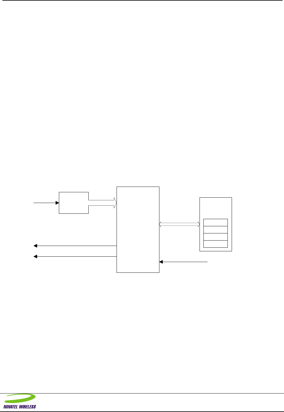
NOVATEL WIRELESS TECHNOLOGIES LTD. 83
AT Command Specification-Expedite and Merlin
Wireless IP Modems
ADC Monitoring
Description:
It is anticipated that many of the users of the Expedite Wireless IP Modem will wish to do so in a mobile
environment, and thus one where the supply voltage may not be constant. To that end, a power condition
control system has been provided.
A block diagram of the battery/power condition system is shown below. It contains:
a. A method of voltage measurement on the modem. This is represented by the AN_IN input, which is
routed on the board to the input of ADC channel 1.
b. A method of reading the voltage measurement from the modem. This is effectively the reading of the
ADC channel 1.
c. A method of identifying when the measurement crosses a threshold. The ability to read the voltage is
matched with the entry in the EE device representing a warning ADC value. If the voltage read from
the ADC is lower than this EE warning value, the warning indication is asserted.
d. A method of specifying the hysteresis associated with the measurements. Once the warning indication
has been asserted, it will only be de-asserted once the ADC measurement is >= Warning +
Threshold.
e. A method of modem shutdown when a critical voltage measurement is reached. If the voltage read
from the ADC is lower than the EE shutdown value, the modem will initiate a de-registration and shut
off.
f. A method of enabling/disabling this monitoring feature. All of these features can be enabled/disabled
with an entry in the EE.
Given that the monitoring functions have been enabled, the signals associated with these functions can be
selectively enabled on any of the GPIO pins on the interface connector. Obviously, if the associated
signals with this feature are not provided on the interface, external devices will not see any of the warnings
and must simply identify when the modem has shutdown.
Signal Name : Low Battery Indication
Asserted when the first threshold is reached. After assertion, it will be de-asserted only if
the voltage measurement is >= low battery threshold + hysteresis count
AN_IN
GPIOn
GPIOn
ADC
CPU
Low Battery Indication
Power Fail Indication
Tx Power Fail
Warning
Shutdown
Hysteresis
Enable
EE

NOVATEL WIRELESS TECHNOLOGIES LTD. 84
AT Command Specification-Expedite and Merlin
Wireless IP Modems
Format:
AT#ADM? Queries the current ADC monitoring mode setting
AT#ADM=0 No ADC monitoring
AT#ADM=1 Enable ADC monitoring mode
AT#ADT? Query ADC monitoring thresholds
AT#ADT=x,y Set the thresholds for the ADC monitor.
AT#ADH=x Sets the hysteresis value
AT#ADN=x,y,z Sets the hysteresis count values.
AT#ADC? Queries the current AN_IN reading.
AT#ADV=r Sets a calibration voltage of the ADC.
For the most part, all ADC measurements will be provided in volts. The idea is that once the ADC readings
have been calibrated such that the firmware knows what ADC value represents what actual input voltage,
all other ADC measurements can now be converted to voltage.
The ADV command forces calibration of the ADC to the currently applied voltage to its input and
associates the parameter voltage to this ADC reading. For instance, a 4.10 volt reference voltage could be
applied to the AN_IN pin and then the following command “AT#ADV=4.10” would be sent in program
mode. Upon receipt of this command, the raw ADC reading would be sampled and averaged for 10
readings and the result saved and associated with the voltage of 4.10 volts. All other ADC functions can
now use voltage values based on this calibrated point and a mathematical relationship.
In the case of the thresholds, the values entered will represent the ADC voltage at which the Low Battery
Indication(x) and the modem shutdown(y) will occur, respectively. The hysteresis value entered is a
representation of how much the voltage reading must rise once the Low Battery Indication has been given
before the Low Battery Indication will be de-asserted. The counts indicate the number of measurements
(with a 1 second period) over the three transition points that must be observed before a valid transition is
identified . This ensures that minor transgressions are not identified as failures until they have been
qualified through the use of the counts. The three counts represent the additional qualification of
transitions from good->low (x), low->off (y), and low->good (z) in the command “AT#AND=x,y,z”.
There will be cases where the AN_IN measurement would be useful to customers/users as an extra ADC
measurement block, but where the power condition monitoring use of the readings are not desired. In this
case, the configuration would be to disable the ADC monitoring mode ( AT#ADM=0 ) but still use the
AT#ADC? queries to identify the voltage at the ADC directly. The host software is then free to use this
reading however they wish.
Example:
As an example of how this may be used, we will assume the following conditions:
• the supply voltage on the board is externally connected to the AN_IN pin on the connector
• an LED is connected to GPIO 2, which we want to use for Low Voltage indications.
• we wish for the Low Voltage indication to trigger at 3.5V, from a regulated 4.OV regulator.
• we wish to initiate a shutdown of the modem if the modem identifies a voltage of 3.3V.
• we wish to de-assert any Low Voltage indication if the voltage rises to 3.6V.
• we wish for 5 counts of each voltage to be observed before we accept the transition.

NOVATEL WIRELESS TECHNOLOGIES LTD. 85
AT Command Specification-Expedite and Merlin
Wireless IP Modems
Configuration:
In order to use these features, we must perform some configuration of the system to reflect our desires.
The order of events to configure the system is as follows:
AT\APROG,NRM6812 *enter program mode
AT#ADV=4.0 *assumes that the voltage input currently is 4.0 volts
AT#ADV=3.5,3.3 * configures the warning and shutdown thresholds
AT#ADH=0.10 * configures the hysteresis to be 3.6V-3.5V or 0.10V
AT#ADN=5,5,5 * configures the hysteresis counts to be 5 readings
AT#ADM=1 * enables the low voltage monitor
ATIO2=10 * enables the Low Battery Indication signal on GPIO2.
AT&W * saves all settings.
This completes all configuration functions associated with the desired power monitoring system that we
defined. The system will now perform the following monitoring:
If voltage is >= 3.5V, no indications
If voltage is 3.3V <= v <= 3.5 for 5 counts, low battery indication is given and LED lights
If voltage rises above 3.6V for 5 counts then, low battery indication is removed and LED turns off
If voltage falls below 3.3V, unit powers off.
Validity:
This command is valid for AT Command mode only.
Once the monitoring functions have been enabled, the shutdown functions will operate. However, the
signals associated with the warnings will only appear on the interface if the Programmable GPIO pins
have been configured to report the associated signals.
Other Considerations:
The voltage measurement is also available through MSCI commands.
Related Topics:
General Purpose IO, Program Mode, Save Profile command

NOVATEL WIRELESS TECHNOLOGIES LTD. 86
AT Command Specification-Expedite and Merlin
Wireless IP Modems
Ping Command
Description:
The Ping command causes the modem to transmit a single ICMP packet of the specified size to the
ICMP/PING entity of the specified address. The data sent is a simple random pattern that the targeted
destination will return in the same format as it was sent. If the packet is returned, then the path from the
modem to the destination address location is intact. If the message is not returned then the path may not
be intact or the destination address may not be able to respond. The Ping command is a very useful tool
in trouble shooting problems and confirming the modems operation.
Upon issuing the Ping command the modem will send the ICMP Ping message to the destination address.
The modem will wait for a return message. If the destination address returns the Ping message before 20
seconds has elapsed, an OK result code is emitted. If the Ping message is not returned in less than 20
seconds, an ERROR result code is emitted. Additional PING commands must not be issued if a PING
command is already in progress, you must wait for either the OK or the ERROR response.
The ping command can be used to send messages up to 128 bytes in length by adding a forward slash
and a number, 1 to 128, afterwards. If no forward slash is included the Ping message will be 32 bytes in
length.
Format:
ATPING<XXX.XXX.XXX.XXX>/<Length> To send a ICMP Ping message
IPaddress format XXX.XXX.XXX.XXX
where XXX is a number [0 to 255]
Length value range [1 to 128]
Validity:
Other Considerations:
In earlier versions of the modem software a BUSY result code was emitted upon transmitting the ICMP
Ping message. There is currently no trace route function within the modem. This function is resident in
Windows 95 and can be run using PPP or SLIP and the external stack.
Related Topics:

NOVATEL WIRELESS TECHNOLOGIES LTD. 87
AT Command Specification-Expedite and Merlin
Wireless IP Modems
Power Boost
Description:
This feature provides support for an external 3watt booster.
Format:
ATAC? To query the configuration
ATAC=0 To turn off 3 watt booster support
ATAC=1 Configuration for 3 watt booster compatible antenna
Validity:
Other Considerations:
There is also an input signal that can be configured to provide this selection as well.
Related Topics:

NOVATEL WIRELESS TECHNOLOGIES LTD. 88
AT Command Specification-Expedite and Merlin
Wireless IP Modems
Message Waiting
Description:
This command turns on the Message Waiting signal if it exists.
Format:
ATMW? To query the state of the signal
ATMW=1 To turn on the Message Waiting signal
ATMW=0 To turn off the Message Waiting signal
Validity:
Obviously, this feature is only valid if there is an output pin associated with this signal.
Other Considerations:
Related Topics:

NOVATEL WIRELESS TECHNOLOGIES LTD. 89
AT Command Specification-Expedite and Merlin
Wireless IP Modems
Internal MRU Setting
Description:
This feature defines the maximum negotiated MRU size during a PPP session. In many host systems, the
host stack will configure a default MRU size from its own defaults, but this may not be the optimum size
for the CDPD network. Further, some implementations of host TCP/IP stack do not allow the modification
of this default by the users. Therefore, in order to properly support these stacks in a wireless CDPD
environment, the ability to dictate the negotiated MRU size to an optimum value regardless of host
configuration will be supported in this register.
Format:
AT#MRU? To query the current setting
AT#MRU=xxx Set the MRU value
By default, the MRU recommended by the CDPD system is approximately 512 bytes.
To set the default MRU size to 512, you would enter the following:
AT\APROG,NRM6812 - enter PROGRAM mode of operation
AT#MRU=512 - set the value to 512
AT&W - to save it
Validity:
This value is configurable in PROGRAM mode only.
Other Considerations:
Related Topics:

NOVATEL WIRELESS TECHNOLOGIES LTD. 90
AT Command Specification-Expedite and Merlin
Wireless IP Modems
TCP Suspension Enable
Description:
This allows any TCP session to be suspended.
Format:
AT#TCPX? Query TCP suspend enable
AT#TCPX=0 Disable TCP suspend feature
AT#TCPX=1 Enable TCP suspend feature
Validity:
Other Considerations:
Related Topics:

NOVATEL WIRELESS TECHNOLOGIES LTD. 91
AT Command Specification-Expedite and Merlin
Wireless IP Modems
Call Progress Result Mode
Description:
Format:
ATX? Query the call progress selection
ATX=xx Set the call progress selection
Validity:
Other Considerations:
Related Topics:

NOVATEL WIRELESS TECHNOLOGIES LTD. 92
AT Command Specification-Expedite and Merlin
Wireless IP Modems
Answer
Description:
This feature represents of the normal ATA answer command. In this system, the ATA will be sent by the
host to release any pending push messages, which would have asserted the Ring Indication line of the
modem interface.
Format:
ATA To answer a Ring Indication
Validity:
Other Considerations:
Related Topics:

NOVATEL WIRELESS TECHNOLOGIES LTD. 93
AT Command Specification-Expedite and Merlin
Wireless IP Modems
Telnet Echo
Description:
A command to assist in Telnet terminal emulation. This command and the associated S register
determine how characters are echoed, either locally, remotely or with no echo.
Format:
ATS60? Queries echo mode
ATS60=0 No echo
ATS60=1 Local echo (default)
ATS60=2 Remote echo
Validity:
Other Considerations:
Related Topics:

NOVATEL WIRELESS TECHNOLOGIES LTD. 94
AT Command Specification-Expedite and Merlin
Wireless IP Modems
Modem Identification
Description:
This feature allows another AT command to query the Modem ID or EID value.
Format:
ATI Queries modem EID
OR
ATI0 Queries modem EID
Validity:
Other Considerations:
Related Topics:
The ATI0 command can be used for the same function.

NOVATEL WIRELESS TECHNOLOGIES LTD. 95
AT Command Specification-Expedite and Merlin
Wireless IP Modems
Friends Mode
Description:
In “Friends” mode, the modem can be configured to reject all messages received that do not originate
from a “friendly” IP address. Up to 10 “friendly” IP addresses can be entered. Once a series of “friendly” IP
addresses or ranges have been entered, enabling “Friends” mode will block reception of data except from
IP addresses in the list. If a message arrives that is not from a “friend” and “Friends” mode has been
enabled, the message will be silently discarded.
Format:
ATFM=0 “Friends” mode disabled
ATFM=1 “Friends” mode enabled
ATFM? Queries the “Friends” mode setting
ATFn=a.b.c.d Sets entry n in “Friends” list to be IP address a.b.c.d
ATF? Queries all 10 entries in the “Friends” list.
In the “Friends” list, entries are indexed from 0 so valid entry positions are 0-9.
When defining IP addresses, 255 can be used as a wildcard.
As an example, suppose that you wish to only accept messages from IP 125.125.125.128 and from any IP
in the 210.180.45 subnet. This could be configured with the following commands:
ATF1=125.125.125.128
OK
ATF2=210.180.45.255
OK
ATF?
0=125.125.125.128
1=210.180.45.255
2=0.0.0.0
3=0.0.0.0
4=0.0.0.0
5=0.0.0.0
6=0.0.0.0
7=0.0.0.0
8=0.0.0.0
9=0.0.0.0
OK
ATFM=1
OK
Validity:
This security feature is only available in the TCP and UDP PAD modes, and the AT command mode. This
security feature is NOT available when a PPP or SLIP data mode is used.
The “Friends” mode feature can be configured in both AT mode or Program mode. Modifications to the
“Friends” list are saved immediately, regardless of mode.

NOVATEL WIRELESS TECHNOLOGIES LTD. 96
AT Command Specification-Expedite and Merlin
Wireless IP Modems
Other Considerations:
Related Topics:

NOVATEL WIRELESS TECHNOLOGIES LTD. 97
AT Command Specification-Expedite and Merlin
Wireless IP Modems
Stack Check
Description:
This feature allows users to query the number of unused bytes on the stack. This query is useful in
diagnosing stack related problems. It is assumed that this command will not be normally used by users,
but may be useful for Customer Service personnel. The value returned is a decimal representation of the
number of unused bytes on the stack.
Format:
ATSC? Queries the number of bytes unused in the stack.
Validity:
Other Considerations:
Related Topics:

NOVATEL WIRELESS TECHNOLOGIES LTD. 98
AT Command Specification-Expedite and Merlin
Wireless IP Modems
Quiet Mode
Description:
This feature allows for Quiet mode of AT operation. In this mode, there are no responses sent to the host
for any AT command entered.
Format:
ATQ? Queries the current setting of Quiet Mode
ATQ0 Disables Quiet Mode (normal responses)
ATQ1 Enables Quiet Mode
Validity:
The “Quiet” mode setting can be set in either AT or Program mode. However, if set in AT mode, the
setting is temporary and will be reset at the next power cycle.
Other Considerations:
Related Topics:
Echo and Verbose Mode of AT Responses.

NOVATEL WIRELESS TECHNOLOGIES LTD. 99
AT Command Specification-Expedite and Merlin
Wireless IP Modems
Registration Mode
Description:
This feature allows control of whether or not the modem will attempt to register upon initialization and to
control when it will attempt registration at other times.
When registration mode is set to automatic, the modem will begin attempting to become registered on the
CDPD network as soon as it is initialized. When registration mode is manual, the modem will wait until
commanded to register before making such attempts. The modem can be commanded to register directly
by executing the ATO command, or by entering one of PPP or SLIP data modes (AT\APPP or AT\ASLIP
respectively). The modem can be commanded to deregister if registered and to cease attempting to
register by executing the ATH3 command. It can also be commanded to deregister and cease attempts to
register by exiting PPP or SLIP mode IF it was not trying to register prior to entering that mode. That is, if
it started to register because it entered the data mode, it will stop trying to register when it leaves that
mode.
Format:
ATREGMD? Queries the current setting of Registration Mode
ATREGMD=0 Sets automatic registration mode
ATREGMD=1 Sets manual registration mode
ATREGST? Queries current registrations status:
0 = not currently attempting to register, 1 = currently
registered, or attempting to register
ATO Begin attempting to register if not already doing so
ATH3 Deregister if registered and cease further attempts to
register.
Validity:
ATREGMD can only be changed in program mode and only has effect at modem initialization time. The
other commands are only effective in AT mode.
Other Considerations:
Related Topics:

NOVATEL WIRELESS TECHNOLOGIES LTD. 100
AT Command Specification-Expedite and Merlin
Wireless IP Modems
Fixed Parameters
The following behaviors are fixed for the NRM.
BEHAVIOR SETTING Equivalent
AT command
Online Mode Echo Disabled ATF0
Extended Result
Codes Enable all ATX2
Transmit Control Automatic timed AT\T1
Subscriber Identity NRM supports only one NEI. AT\S0

NOVATEL WIRELESS TECHNOLOGIES LTD. 101
AT Command Specification-Expedite and Merlin
Wireless IP Modems
Unsupported Commands
The following commands (listed in CDPD Part 2014) are not supported by the NRM. If these commands,
or any other AT command not described above, are received, the NRM will return an ERROR response.
ATF Online Mode Echo
AT\F Set Data Forwarding Operation
AT\M Manual Transmit Control
AT\R Network Registration Control6
AT\S Set Subscriber Identity
AT\T Automatic Transmit Control
AT&C DCD mode
Unsupported Functions
The following functions (listed in CDPD Part 2014) are not supported by the NRM. The commands are
supported such that if they are received during operation, an OK response will be returned but they
perform no real functions. These commands are primarily supported to ensure backward compatibility with
previously released AT Command sets of our product.
ATS102 Pending Data Disposition
ATS114 Set Channel Quality Override Mode
ATS115 Set Channel Quality Override Parameters
6 The NRM automatically registers with the CDPD network upon power on/reset.

NOVATEL WIRELESS TECHNOLOGIES LTD. 102
AT Command Specification-Expedite and Merlin
Wireless IP Modems
Appendix A: AT Command Set Quick Reference
ATS250? Query Wake Up Protocol State 15
ATS250=1 Enable Push Technology 15
ATS250=0 Disable Push Technology 15
ATS251? Query Number of Pending Messages 15
ATS252? Query First Push Message 15
ATS253? Query Type of First Push Message 15
ATS254=1 Discard Current Message 15
AT\ASLIP The command to enter SLIP mode 16
AT\APPP The command to enter PPP Mode 17
AT#ZZ? Sleep status query command 21
AT#ZZ=0 Disable sleep feature 21
AT#ZZ=1 Enable Long cycle sleep 21
AT#ZZ=2 Enable short cycle sleep 21
AT#NSZZ Out-of-service Sleep status query command 22
AT#NSZZ=0 Disable out-of-service sleep feature 22
AT#NSZZ=1 Enable out-of-service sleep feature 22
AT#NSZZTM=p,b,c,n Configure out-of-service sleep feature 22
ATMD0 For AT Command mode at power-up 25
ATMD1 For SLIP Data mode at power-up 25
ATMD2 For PPP Data mode at power-up 25
ATMD3 For UDP Data mode at power-up 25
ATMD83 UDP with no IP address verify on incoming packets 25
ATI3 Query Hardware configuration 26
AT#NH=number Set Hardware configuration 26
AT#NH? Query Hardware configuration 26
AT\APROG,NRM6812 Enter program mode 28
AT&W Save changes and exit program mode 28
ATZ Exit without saving changes 28
ATE0 Disable Local Echo 29
ATE1 Enable Local echo 29
ATV0 To enable the response to be in the numeric format 30
ATV1 To enable the response to be in plain text 30
ATIO1? To query the current setting of GPIO1 31
ATIO1=<code> To set the operating function of GPIO1 31
ATIO2? To query the current setting of GPIO2 31
ATIO2=<code> To set the operating function of GPIO2 31
ATIO3? To query the current setting of GPIO3 31
ATIO3=<code> To set the operating function of GPIO3 31
ATIO4? To query the current setting of GPIO4 31
ATIO4=<code> To set the operating function of GPIO4 31
ATIO5? To query the current setting of GPIO5 31
ATIO5=<code> To set the operating function of GPIO5 31
ATIO6? To query the current setting of GPIO6 31
ATIO6=<code> To set the operating function of GPIO6 31
ATZ To perform a modem soft reset 33
AT\N? To determine current setting use 34
AT\N1 To set the unit to A side only 34
AT\N2 To set the unit to B side only 34
AT\N3 To set the unit to A side Preferred 34
AT\N4 To set the unit to B side Preferred 34
AT\P=oldpwd,newpwd,newpwd To change the password the command 35
+++<password> Escape Sequence 36
AT\Q? Query current flow control setting 37
AT\Q0 Set flow control off (Default) 37
AT\Q2 Set Flow control on (Hardware) 37
ATH0 Terminate session & return to AT Command mode 38
ATH1 Terminate session & return to AT Command mode 38
ATH2 Terminate session & return to AT Command mode 38
ATH3 Terminate session, de-register, and return to AT Command mode 38
ATH4 Terminate session, de-register and shutdown 38
AT&F Restore factory defaults 39
ATS23? To determine the current line setting 40

NOVATEL WIRELESS TECHNOLOGIES LTD. 103
AT Command Specification-Expedite and Merlin
Wireless IP Modems
AT&L? To determine the current line setting 40
ATS23=<S>,<D><P><N> To change the serial port settings 40
AT&L<S>,<D><P><N> To change the serial port settings 40
AT&V View active profile 42
AT&W Save changes 43
ATS53? Query destination IP Addr /Port 44
ATS53=T1.2.3.4/1 Set the destination IP Addr/Port 44
AT#X=1 Enter debug mode 45
AT#X=0 Exit debug mode 45
ATS0? Auto Answer Query 46
ATS0=1 Set Auto Answer mode ON 46
ATS0=0 Set Auto Answer mode OFF 46
ATS7? Connection Timeout value 47
ATS50? Data Forwarding Idle Time-out 48
ATS51? Query Data Forwarding Idle Character 49
ATS51=0 Disabled Data Forwarding Idle Character 49
ASS51=aa Data Forwarding Idle Character values of 1-255 49
ATS82=0 regular mode 50
ATS82=1 not used (reserved) 50
ATS82=2 Half-Open mode enabled 50
ATS83? Query UDP Open Timeout 50
ATS83=60 Set UDP Open Timeout 50
ATS103? To determine the current setting 51
ATS103=1 To enable status reporting 51
ATS103=0 To disable status reporting 51
ATS110? IP Address and Port 53
ATS110=<Address>/<port> To set the IP address 53
ATS111? Query Service ID Preferences 55
ATS111=<SPI>/<SPNI>/<WASI> Set Service ID Preferences 55
ATS112? To determine the current channel scan mode 56
ATS112=0 Any channel 56
ATS112=1 Hot List Only 56
ATS112=2 Hybrid 56
ATS113? Channel List query 58
ATS113=<chan1>,<chan2>,etc. Set channel list 58
ATS116? Query Service ID preference 59
ATS116=0 To only use S111 service ID 59
ATS116=1 To prefer S111 service ID 59
ATS116=2 To not use S111 service ID 59
ATS116=3 To use any service ID 59
ATS117? CDPD Operating Version 60
ATS117=10 To set it for Version 1.0 60
ATS117=11 To set it for Version 1.1 60
ATS210? Query Wireline Compatibility setting 61
ATS210=0 To enable the line feed character 61
ATS210=1 To suppress the line feed character 61
ATS211? Query DTR control setting 62
ATS211=0 To set DTR control ON 62
ATS211=1 To set DTR control OFF 62
ATS211=2 Always assert DSR 62
ATS211=4 Dropping DTR gracefully powers off modem 62
ATS211=8 DSR Control asserted after registration 62
AT&D? Queries DTR mode setting 63
AT&D0 ignore DTR transitions ( S211 = 1 ) 63
AT&D1 normal operation (default) 63
AT&D2 de-asserted DTR powers modem off ( S211 = 4 ) 63
AT&S? To query the current DSR control setting 64
AT&S 0 No control of DSR. It is asserted all of the time 64
AT&S1 Control of DSR is enabled after modem registration. 64
AT&S2 Normal operation of DSR. Asserted when data mode. 64
ATTCPT? Query TCP Timer setting 65
ATTCPT=value [ 0 to 255 minutes] To set the timer value (minutes) 65
ATTCPT=0 To disable the timer 65
ATI0 To determine the EID 66
ATI1 To determine sw version & copyright information 66
ATI2 To determine the manufacturer 66

NOVATEL WIRELESS TECHNOLOGIES LTD. 104
AT Command Specification-Expedite and Merlin
Wireless IP Modems
ATI3 To determine the hardware version 66
ATS57? To determine current network status 67
ATS200? To determine last registration error 70
ATAUTH To reset authentication keys to zero 71
ATS202? To determine the current RSSI value 72
ATS203? To determine the current Block Error Rate 73
ATS204? To determine the current channel 74
ATS205? To determine the current Cellular ID 75
ATS206? To determine the current color code 76
ATS207? To determine the current power level 77
ATS208? To query the current Symbol Error Rate. 78
ATS209? To query the current power product 79
ATAF? Query the authentication failures. 80
ATAF=0 To reset the register to zeros. 80
ATDT<IPaddress>/<port#> To initiate a TCP Session 81
ATDP<IPaddress>/<port#> To initiate a UDP Connection 81
ATDN<Ipaddress> To initiate a Telnet Session. Port 23 is assumed. 81
ATD To use the Default Register 81
AT#ADM? Queries the current ADC monitoring mode setting 84
AT#ADM=0 No ADC monitoring 84
AT#ADM=1 Enable ADC monitoring mode 84
AT#ADT? Query ADC monitoring thresholds 84
AT#ADT=x,y Set the thresholds for the ADC monitor. 84
AT#ADH=x Sets the hysteresis value 84
AT#ADN=x,y,z Sets the hysteresis count values. 84
AT#ADC? Queries the current AN_IN reading. 84
AT#ADV=r Sets a calibration voltage of the ADC. 84
ATPING<XXX.XXX.XXX.XXX>/<Length> To send a ICMP Ping message 86
ATAC? To query the configuration 87
ATAC=0 To turn off 3 watt booster support 87
ATAC=1 Configuration for 3 watt booster compatible antenna 87
ATMW? To query the state of the signal 88
ATMW=1 To turn on the Message Waiting signal 88
ATMW=0 To turn off the Message Waiting signal 88
AT#MRU? To query the current setting 89
AT#MRU=xxx Set the MRU value 89
AT#TCPX? Query TCP suspend enable 90
AT#TCPX=0 Disable TCP suspend feature 90
AT#TCPX=1 Enable TCP suspend feature 90
ATX? Query the call progress selection 91
ATX=xx Set the call progress selection 91
ATA To answer a Ring Indication 92
ATS60? Queries echo mode 93
ATS60=0 No echo 93
ATS60=1 Local echo (default) 93
ATS60=2 Remote echo 93
ATI Queries modem EID 94
ATI0 Queries modem EID 94
ATFM=0 “Friends” mode disabled 95
ATFM=1 “Friends” mode enabled 95
ATFM? Queries the “Friends” mode setting 95
ATFn=a.b.c.d Sets entry n in “Friends” list to be IP address a.b.c.d 95
ATF? Queries all 10 entries in the “Friends” list. 95
ATSC? Queries the number of bytes unused in the stack. 97
ATQ? Queries the current setting of Quiet Mode 98
ATQ0 Disables Quiet Mode (normal responses) 98
ATQ1 Enables Quiet Mode 98
ATREGMD? Queries the current setting of Registration Mode 99
ATREGMD=0 Sets automatic registration mode 99
ATREGMD=1 Sets manual registration mode 99
ATREGST? Queries current registrations status: 99
ATO Begin attempting to register if not already doing so 99
ATH3 Deregister if registered and cease further attempts to register. 99
ATF Online Mode Echo 101
AT\F Set Data Forwarding Operation 101
AT\M Manual Transmit Control 101

NOVATEL WIRELESS TECHNOLOGIES LTD. 105
AT Command Specification-Expedite and Merlin
Wireless IP Modems
AT\R Network Registration Control 101
AT\S Set Subscriber Identity 101
AT\T Automatic Transmit Control 101
AT&C DCD mode 101
ATS102 Pending Data Disposition 101
ATS114 Set Channel Quality Override Mode 101
ATS115 Set Channel Quality Override Parameters 101

NOVATEL WIRELESS TECHNOLOGIES LTD. 106
AT Command Specification-Expedite and Merlin
Wireless IP Modems
Index of AT Commands
+++.......................................................................... 36
AT#ADC................................................................. 84
AT#ADH................................................................. 84
AT#ADM................................................................ 84
AT#ADN................................................................. 84
AT#ADT................................................................. 84
AT#ADV................................................................. 84
AT#MRU................................................................ 89
AT#NH ................................................................... 26
AT#NSZZ ............................................................... 22
AT#NSZZTM ......................................................... 22
AT#TCPX............................................................... 90
AT#X ...................................................................... 45
AT#ZZ .................................................................... 21
AT&C ................................................................... 100
AT&D ..................................................................... 63
AT&F...................................................................... 39
AT&L...................................................................... 40
AT&S...................................................................... 64
AT&V ..................................................................... 42
AT&W .............................................................. 28, 43
ATA ........................................................................ 92
ATAC...................................................................... 87
ATAF...................................................................... 80
AT\APPP ................................................................ 17
AT\APROG............................................................. 28
AT\ASLIP ............................................................... 16
ATAUTH................................................................ 71
ATD ........................................................................ 81
ATDN ..................................................................... 81
ATDP...................................................................... 81
ATDT...................................................................... 81
ATE......................................................................... 29
AT\F...................................................................... 100
ATF................................................................. 95, 100
ATFM ..................................................................... 95
ATH ........................................................................ 38
ATH3 ...................................................................... 98
ATI.............................................................. 26, 66, 94
ATIO....................................................................... 31
AT\M .................................................................... 100
ATMD..................................................................... 25
ATMW.................................................................... 88
AT\N ....................................................................... 34
ATO ........................................................................ 98
AT\P........................................................................ 35
ATPING.................................................................. 86
AT\Q ....................................................................... 37
ATQ ........................................................................ 97
AT\R ..................................................................... 100
ATREGMD............................................................. 98
ATREGST .............................................................. 98
AT\S...................................................................... 100
ATS0....................................................................... 46
ATS102................................................................. 100
ATS103................................................................... 51
ATS110................................................................... 53
ATS111................................................................... 55
ATS112................................................................... 56
ATS113................................................................... 58
ATS114................................................................. 100
ATS115................................................................. 100
ATS116................................................................... 59
ATS117................................................................... 60
ATS200................................................................... 70
ATS202................................................................... 72
ATS203................................................................... 73
ATS204................................................................... 74
ATS205................................................................... 75
ATS206................................................................... 76
ATS207................................................................... 77
ATS208................................................................... 78
ATS209................................................................... 79
ATS210................................................................... 61
ATS211................................................................... 62
ATS23..................................................................... 40
ATS250................................................................... 15
ATS251................................................................... 15
ATS252................................................................... 15
ATS253................................................................... 15
ATS254................................................................... 15
ATS50..................................................................... 48
ATS51..................................................................... 49
ATS53..................................................................... 44
ATS57..................................................................... 67
ATS60..................................................................... 93
ATS7....................................................................... 47
ATS82..................................................................... 50
ATS83..................................................................... 50
ATSC ...................................................................... 96
AT\T...................................................................... 100
ATTCPT ................................................................. 65
ATV ........................................................................ 30
ATX ........................................................................ 91
ATZ................................................................... 28, 33