Novatel Wireless NRM-3800 CDPD Data Transceiver User Manual Manual
Novatel Wireless, Inc. CDPD Data Transceiver Manual
Contents
Manual
1
3 Watt Installation Guide
DRAFT
2
3 WATT INSTALLATION GUIDE 1
Introduction 4
Configuration 4
Contents 4
Accessories 4
SAFETY NOTICES AND LIABILITIES 5
Warning: 5
Liability 5
INTERFERENCE STATEMENTS 6
Federal Communications Commission Radio Frequency Interference Statement 6
Caution: 6
ICES-003 Statement 6
INSTALLATION 7
POWER CABLE INSTALLATION 8
ANTENNA INSTALLATION 9
LED'S AND CONNECTORS 10
HOW TO START AND LAUNCH APPLICATIONS 11
SPECIFICATIONS 12
TECHNICAL SUPPORT 14
How to Contact Novatel Wireless Technical Support 14
What Customer Support Can Do For You 14
POWER ISSUES 15
4
Introduction
The purpose of this on-line help system is to describe the procedures required to install 3 Watt
Modem in a vehicle environment. If you require information on alternate installations please
contact our technical support department at 1-888-888-9231 or email at:
support@novatelwireless.com
Configuration
The 3 Watt Modem can be purchased in the following configurations:
• Base Model (available in bulk or individual packaging)
• GPS Modem (available in bulk or individual packaging)
Contents
The 3 Watt Modem is shipped with the following contents:
• 3 Watt Modem
• Power Cable
• Mounting Hardware
• CD-ROM with Modem Manager software
• Installation Guide
• Trouble Shooting Guide
• Warranty Card
Accessories
The following accessories are available to be added to your 3 Watt Modem.
• GPS add on card (Trimble)
• GPS add on card (Rockwell)
• Panel mount face plate
5
Safety Notices and Liabilities
Warning:
This product is not to be used in any environment where radio frequency equipment is prohibited
or restricted in its use. This includes aircraft/airports, hospitals, and other sensitive electronic
areas.
Liability
Novatel Wireless Inc. assumes no responsibility for any damage or loss resulting from the use of
its products. Novatel Wireless assumes no responsibility for any loss or claims by third parties,
which may arise through the use of its products. Novatel Wireless assumes no responsibility for
any damage or loss caused by the deletion or loss of data as a result of malfunctions or repairs. Be
sure to make backup copies of all-important data on other media to protect against data loss.
The information disclosed herein is the exclusive property of Novatel Wireless and no part of this
publication may be reproduced or transmitted in any form or by any means including electronic
storage, reproduction, execution or transmission without the prior written consent of Novatel
Wireless. The information contained in this document is subject to change without notice and
should not be construed as a commitment by Novatel Wireless unless such commitment is
expressly given in a covering document.
6
Interference Statements
Federal Communications Commission Radio Frequency Interference Statement
This equipment has been certified to comply with the limits for a class A digital device, pursuant
to part 15 of the FCC rules. These limits are designed to provide reasonable protection against
harmful interference in residential situations. This equipment generates, uses, and can radiate radio
frequency energy. If not installed and used in accordance with the instructions, it may cause
harmful interference to radio or television reception, which can be determined by turning the
equipment on and off. You are encouraged to try to correct the interference by one or more of the
following measures.
• Reorient or relocate the receiving antenna of the selected television, radio, or cordless telephone.
• Increase the separation between the equipment and the receiver.
• Connect the equipment into an outlet on a circuit different from that to which the receiver is
connected.
• Consult the dealer or an experienced radio/television technician for additional suggestions.
Caution:
Changes or modifications to this equipment not expressly approved by Novatel Wireless could
void the user’s authority to operate the equipment.
ICES-003 Statement
This Class B digital apparatus meets all requirements of the Canadian Interference-Causing
Equipment Regulations.
7
Installation
It is recommended that your 3 Watt modem be installed in one of the following locations to
facilitate ease of installation and monitoring of modem performance:
• Under the dash/console
• On the center console
• In the trunk (preferably off the floor)
• Any other location with ease of access and visibility of the unit's LED's
Use the following guidelines when choosing an installation location for the modem:
• Ensure there is no hazard when drilling the mounting holes. (wiring, fuel, etc)
• Select a location that does not interfere with the seat travel or door movement.
• Select a location that is not a source of heat.
• Ensure the modem has at least 1 inch of clearance on all sides for cooling.
• Locate the modem away from any electronic control systems in the vehicle to prevent
possible RF interference from the modem. (Although the 3 Watt modem passes all FCC
requirements, we cannot ensure that the automobile electronics are not susceptible to the
modem transmitted power)
• If possible place the modem on the same side of the vehicle as the battery. This will simplify
the routing of the power cable.
Drill holes into the vehicle appropriate to the chosen location and install the modem using the
provided mounting hardware.
8
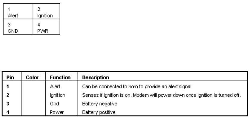
Power Cable Installation
Connect the provided power cable as shown in the pinout diagram shown below.
The modem will not work if the vehicle does not have a negative ground. There are no fuses on
the power cable, because an internal resettable fuse is included with the modem.
The function of the power pins and color of wires are as follows:
9
Antenna Installation
When choosing an antenna for your modem installation you should select one that meets the
following specifications:
• Cellular frequency band
• TNC connector
• 50 ohm cable
• 3 dBi gain (+/- 2 dBi)
Please follow these recommendations when installing your antenna:
• Install the antenna only according to its manufacturer instructions.
• Connect the antenna's TNC connector to the modem's RF connector.
• Only mount the antenna where designed to be mounted.
• Do not install a glass mount antenna on metallic glass or with the antenna conductor placed
over the rear window heating wires.
• Do not mount a roof mount antenna on a fiberglass or plastic surface.
Care should be taken when choosing the location on the vehicle for the antenna installation:
• Select the highest possible point on the vehicle to install the antenna.
• Select a location that has easy access to a cable run to simplify connecting the antenna to the
modem.
• Select a cable run that is free of hazards such as excessive heat, possible screw punctures or
that requires pinching of the cable when installing it.
• Select a cable run that allows the cable to remain fixed in place. A cable that has to move in
hoods/doors or other moveable locations on the vehicle will eventually fray and break.
• Select a cable route that is at least 8 inches (20.3 centimeters) away from any microprocessor
controlled electronic equipment.
10
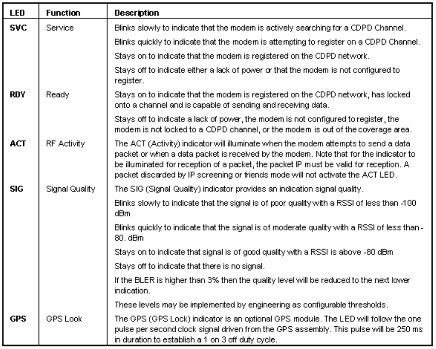
LED's and Connectors
The modem has 5 LED indicators on its front face as shown in the diagram. The functions of each
of the LED's are explained in the table.

11
How to Start and Launch Applications
To run applications that connect to the Internet that make use of the Internet, you must first run the
Wireless Modem Manager. There are two ways to start the Wireless Modem Manager:
• Run the Wireless Modem Manager by click on the Windows Start button and select Programs
->Novatel Wireless->Serial->Wireless Modem Manager
• Run the Wireless Modem Manager by double clicking on the Wireless Modem Manager Icon
on your desktop.
Under Windows, the Wireless Modem Manager will display a “Ready” message in the status
message area and the status indicator will turn green when the modem is registered. At this point,
you can start your other Internet applications and they will automatically use the existing
connection created by the Wireless Modem Manager to connect to the Internet. Using Wireless
Modem Manager also gives you the benefit of an icon in the status area of the taskbar (next to the
clock). The Wireless Modem Manager icon (a modem with an antenna) will either be red to
indicate that you do not have a valid Internet connection, or green to indicate that your modem has
registered onto the wireless network, and is ready to be used with your applications.
Modem not ready for use (unregistered)
Modem ready for use (registered)
Under Windows CE, the Wireless Modem Manager displays three checkboxes on the Config tab.
These three checkboxes are:
• Cellular Signal Present
• Wireless IP Service Detected
• Modem Ready
When the Modem Ready is checked, your modem is registered and ready for use. At this point,
you can start your other Internet applications and they will automatically use the existing
connection created by the Wireless Modem Manager to connect to the Internet. Using the Wireless
Modem Manager also gives you the benefit of an icon in the status area of the taskbar (next to the
clock). The Wireless Modem Manager icon (the Novatel Wireless logo) will either be gray to
indicate that you do not have a valid Internet connection, or solid black to indicate that your
modem has registered onto the wireless network, and is ready to be used with your applications.
Modem not ready for use (unregistered)
Modem ready for use (registered)
12
Specifications
Case:
• Black Aluminium extrusion chassis and metal face plates
• Base unit with flanges for direct mounting
• Dust and water resistant splash proof cover
Dimensions:
• Length: 8.5" / 21.25 cm
• Width: 5.5" / 13.75 cm
• Height : 1.5" / 3.75 cm
Antenna Connector:
• TNC, 50 ohms, VSWR 1:15 nominal, 1:20 maximum
Power Connector:
• DB-9 connector with R232 signal levels
Indicators:
• SVC (Service), RDY (Ready), ACT (RF Activity), SIG (Signal Quality), GPS (GPS Look)
Frequency:
• Standard CDPD ( 824 MHz to 896 MHz)
Power Requirements:
• 13.6 V +/-20% nominal, 30 volts maximum, 9 volts minimum, 2 amps maximum input
current
Power Protection:
• Reverse polarity protection and self correcting current limit
Operating Temperature:
• -30° to 70° C
Vibration Conformance:
• MIL-STD 202F and CDPD standard
• 15 G six axis, 5 to 200 Hx operating
Shock:
13
• CDPD Standard 20 G axis non-operating
Humidity:
• 5% to 95% (non-condensing)
Wireless Protocols:
• Fully Integrated CDPD 1.1 ( Class 1) 3 watt unit
Cables:
• Marine grade, 14-gauge power cable, 12-volt supply, ground, ignition sense and alert output
Regulatory Approval:
• FCC part 22 and part 15, and Industry Canada
Warranty:
• Full 3 year warranty, optional extended warranty available

14
Technical Support
If you are in need of technical support regarding the operation of your 3 Watt Modem, contact the
Novatel Wireless Customer Support Center, or refer to the following resources.
• Your Wireless IP Service Provider. Contact information may be found in the Wireless
Configuration Wizard or on the Novatel Wireless website at http://www.novatelwireless.com.
• The on-line help that can be accessed from the 3 Watt Modem’s CD-ROM
• The product support information on the Novatel Wireless website at
http://www.novatelwireless.com.
How to Contact Novatel Wireless Technical Support
Technical and Customer Support can be contacted toll-free by telephone at
1-888-888-9231 or by using our general support email address at support@novatelwireless.com
What Information Technical Support Personnel Might Need From You
• Your computer operating system (Windows 95/98/NT4.0/2000/CE).
• The version of the operating system (e.g. Windows 95 Version B, NT 4, and CE 2.1).
• The Electronic Identification number of the modem.( Found on the 3 Watt label, or in the
Wireless Modem Manager)
• The version of the software for Wireless Modem Manager and Wireless Configuration
Wizard software. (Found in the About screen).
• Your Wireless Internet Provider (Carrier, CDPD Service Provider)
• Geographic Location of Use.
What Customer Support Can Do For You
Customer support can assist you in the following ways:
• Technical support to help you get your get the 3 Watt Modem operating.
• General information on all of Novatel Wireless Technology products and services.
• Direct sales of Novatel Wireless Technology products and services.
• Information on third party solutions and vendors.
15
Power Issues
Your 3 Watt Modem is designed with state-of-the-art power saving features.
Transmitting
The 3 Watt modem consumes the greatest amount of power when transmitting. Your 3 Watt
modem transmits only when it needs to send data or acknowledge data to the network. For
example, you may be “connected” and browsing the Internet, but the transmitter will not turn on
unless the modem needs to send data to a website.
Sleep Mode
Your 3 Watt modem is equipped with an advanced power saving feature called sleep mode. Sleep
mode allows your 3 Watt modem to shut off almost all power consumption during times when it is
registered with the Wireless IP network, but has no data to send or receive. In this mode, your 3
Watt modem checks for incoming data periodically (about once every couple of minutes). If it
senses that there is data to send or receive, it will resume normal operation. Sleep mode will only
operate when the 3 Watt modem is registered on the network, so it must be in an area with
Wireless IP coverage. Sleep mode is normally enabled, but can be disabled using the Wireless
Modem Manager.
16
Coverage Issues
For the latest Wireless IP (CDPD) coverage information, refer to any of the following websites:
• Your Wireless IP (CDPD) Service Provider website.
• The Novatel Wireless website at http://www.novatelwireless.com.
• The Wireless Data Forum website at http://www.wirelessdata.com.
17