Novatel Wireless NRM-EG301 PCS OEM Module User Manual GPRS Technical Specifications
Novatel Wireless, Inc. PCS OEM Module GPRS Technical Specifications
Contents
- 1. Quick Start Guide
- 2. Users Manual Part I
- 3. Users Manual Part II
- 4. Revised Users manual
Revised Users manual

Technical Manual
with Specifications
Merlin and Expedite GPRS Products
P/N 90023363 Rev. 1.8

Notice: Restricted Proprietary Information
© Copyright Novatel Wireless Technologies Ltd. (2002)
The information contained in this document is the exclusive property of Novatel Wireless Technologies Ltd. All rights
reserved. Unauthorized reproduction of this manual in any form without the expressed written approval of Novatel Wireless
Technologies Ltd is strictly prohibited. This manual may not, in whole or in part, be copied, reproduced, translated, or
reduced to any electronic or magnetic storage medium without the written consent of a duly authorized officer of Novatel
Wireless Technologies Ltd.
The information contained in this document is subject to change without notice and should not be construed as a
commitment by Novatel Wireless Technologies Ltd. unless such commitment is expressly given in a covering document.
Novatel Wireless Technologies Ltd makes no warranties, either expressed or implied, regarding this document, its
merchantability, or its fitness, for any particular purpose.
Printed and produced in Canada.

i
P/N 90023363 Revision 1.9
Table of Contents
Chapter 1: Product Overview
Introduction to GSM and GPRS ....................................................................................2
GSM Technology............................................................................................................................. 2
Advantages of GPRS ...................................................................................................................... 3
GPRS Network Architecture............................................................................................................ 4
Data Rates ...................................................................................................................................... 6
SIM .................................................................................................................................................. 6
Operational Features......................................................................................................7
Notices.............................................................................................................................8
Safety Warning ...................................................................................................................................... 8
FCC RF Interference Statement ............................................................................................................ 9
Regulatory Requirements ...................................................................................................................... 9
Technical Support Contacts................................................................................................................. 11
Limited Warranty and Liability.............................................................................................................. 11
Icon Usage .................................................................................................................................... 14
Chapter 2:
Specifications
Merlin GPRS PC Card Specifications .........................................................................15
Merlin General Specifications .............................................................................................................. 16
Merlin Physical Appearance ................................................................................................................ 18
PC Card Connector Pin Assignment.................................................................................................... 20
Interfaces ............................................................................................................................................. 22
Modes .................................................................................................................................................. 23
Expedite G301 OEM Module Specifications...............................................................24
Expedite General Specifications ................................................................................................... 24
Expedite Physical Appearance...................................................................................................... 25
Interfaces ............................................................................................................................................. 26
Modem Power-On and Wake up Strategy..................................................................................... 27
Serial Ports.................................................................................................................................... 28
GPIO ............................................................................................................................................. 28
Analog to Digital Converter (ADC) ................................................................................................ 29
Audio Port...................................................................................................................................... 29
Subscriber Identity Module Support ..............................................................................................29
Electrostatic Discharge and Electromagnetic Interference............................................................ 29
Expedite Electrical Specifications ........................................................................................................ 30
Power Supply ................................................................................................................................ 30
Interface Signals............................................................................................................................ 31
Power-on and Wake-up Timing Characteristics ............................................................................ 34
Baseband Connector on Expedite................................................................................................ 36
Baseband Mating Connector on the Host ..................................................................................... 37
Baseband Connector Pin Numbering............................................................................................ 37
Antenna Port ................................................................................................................................ 38
Antenna Connector ....................................................................................................................... 38
Mating Antenna Connector............................................................................................................ 38

ii
Revision 1.9 P/N 90023363
Mounting Features.........................................................................................................................38
Air Interface .................................................................................................................. 38
Subscriber Identification Module (SIM)...................................................................... 39
Modes of Operation ..................................................................................................... 40
Sleep..............................................................................................................................................40
SMS Messaging.............................................................................................................................40
Circuit Switched .............................................................................................................................40
GPRS Data ....................................................................................................................................40
Standby..........................................................................................................................................41
Application Information............................................................................................... 41
Chapter 3: AT Commands
AT Command Set by Function .............................................................................................................44
AT Command Set by Name .................................................................................................................53
A/..........................................................................................................................................................53
+++ .......................................................................................................................................................53
ATA ......................................................................................................................................................54
ATD[<n>][mgsm>] ................................................................................................................................54
ATD[<mem><loc>][<mgsm>] ...............................................................................................................56
ATD[<ploc>][<mgsm>] .........................................................................................................................57
ATD[<str>][<mgsm>] ............................................................................................................................59
ATDL ....................................................................................................................................................61
ATE ......................................................................................................................................................62
ATH ......................................................................................................................................................62
ATI........................................................................................................................................................63
ATI0......................................................................................................................................................63
ATL.......................................................................................................................................................63
ATM......................................................................................................................................................64
ATO......................................................................................................................................................64
ATP ......................................................................................................................................................65
ATQ......................................................................................................................................................65
ATS0 ....................................................................................................................................................66
ATS2 ....................................................................................................................................................66
ATS3 ....................................................................................................................................................67
ATS4 ....................................................................................................................................................67
ATS5 ....................................................................................................................................................68
ATS6 ....................................................................................................................................................69
ATS7 ....................................................................................................................................................69
ATS8 ....................................................................................................................................................70
ATS10 ..................................................................................................................................................70
ATS12 ..................................................................................................................................................71
ATT ......................................................................................................................................................71
ATV ......................................................................................................................................................72
ATX ......................................................................................................................................................72
ATZ ......................................................................................................................................................73
AT&C....................................................................................................................................................74
AT&D....................................................................................................................................................74
AT&F ....................................................................................................................................................74
AT&V ....................................................................................................................................................75
AT&W ...................................................................................................................................................76

iii
P/N 90023363 Revision 1.9
AT+CACM............................................................................................................................................ 76
AT+CALM ............................................................................................................................................ 76
AT+CAMM ........................................................................................................................................... 77
AT+CAOC............................................................................................................................................ 77
AT+CBC............................................................................................................................................... 78
AT+CBST............................................................................................................................................. 79
AT+CCFC ............................................................................................................................................ 80
AT+CCLK............................................................................................................................................. 81
AT+CCUG............................................................................................................................................ 82
AT+CCWA ........................................................................................................................................... 82
AT+CCWE ........................................................................................................................................... 84
AT+CDRIND ........................................................................................................................................ 84
AT+CEER ............................................................................................................................................ 85
AT+CEXTBUT ..................................................................................................................................... 85
AT+CEXTHS........................................................................................................................................ 86
AT+CFUN ............................................................................................................................................ 86
AT+CGACT.......................................................................................................................................... 87
AT+CGAPNR....................................................................................................................................... 87
AT+CGAPNW ...................................................................................................................................... 88
AT+CGATT .......................................................................................................................................... 89
AT+CGCLASS ..................................................................................................................................... 89
AT+CGDCONT .................................................................................................................................... 89
AT+CGEREP ....................................................................................................................................... 91
AT+CGMI............................................................................................................................................. 92
AT+CGMM ........................................................................................................................................... 92
AT+CGMR ........................................................................................................................................... 92
AT+CGOI ............................................................................................................................................. 93
AT+CGPADDR .................................................................................................................................... 93
AT+CGQMIN ....................................................................................................................................... 93
AT+CGQREQ ...................................................................................................................................... 94
AT+CGREG ......................................................................................................................................... 95
AT+CGSMS ......................................................................................................................................... 95
AT+CGSN............................................................................................................................................ 96
AT+CHLD ............................................................................................................................................ 97
AT+CIMI............................................................................................................................................... 97
AT+CLCC ............................................................................................................................................ 97
AT+CLCK............................................................................................................................................. 99
AT+CLDTMF...................................................................................................................................... 100
AT+CLIP ............................................................................................................................................ 101
AT+CLIR ............................................................................................................................................ 101
AT+CLTS ........................................................................................................................................... 102
AT+CLVL ........................................................................................................................................... 102
AT+CMEE.......................................................................................................................................... 103
AT+CMGD ......................................................................................................................................... 103
AT+CMGF.......................................................................................................................................... 103
AT+CMGL.......................................................................................................................................... 104
AT+CMGR ......................................................................................................................................... 106
AT+CMGW ........................................................................................................................................ 108
AT+CMSS.......................................................................................................................................... 109
AT+CMUT.......................................................................................................................................... 110
AT+CMUX.......................................................................................................................................... 110
AT+CNMI ........................................................................................................................................... 111
AT+CNUM ......................................................................................................................................... 112
AT+COLP .......................................................................................................................................... 113

iv
Revision 1.9 P/N 90023363
AT+COPN ..........................................................................................................................................114
AT+COPS ..........................................................................................................................................115
AT+CPAS...........................................................................................................................................116
AT+CPBF ...........................................................................................................................................116
AT+CPBR...........................................................................................................................................117
AT+CPBS...........................................................................................................................................118
AT+CPBW..........................................................................................................................................118
AT+CPIN ............................................................................................................................................119
AT+CPMS ..........................................................................................................................................120
AT+CPOL...........................................................................................................................................120
AT+CPUC ..........................................................................................................................................121
AT+CPWD..........................................................................................................................................121
AT+CR ...............................................................................................................................................123
AT+CRC.............................................................................................................................................123
AT+CREG ..........................................................................................................................................124
AT+CRES...........................................................................................................................................124
AT+CRLP ...........................................................................................................................................125
AT+CRSL ...........................................................................................................................................125
AT+CSAS...........................................................................................................................................126
AT+CSCA...........................................................................................................................................126
AT+CSCB...........................................................................................................................................127
AT+CSCS...........................................................................................................................................127
AT+CSDH ..........................................................................................................................................128
AT+CSIM............................................................................................................................................128
AT+CSMINS.......................................................................................................................................129
AT+CSMP ..........................................................................................................................................129
AT+CSMS ..........................................................................................................................................130
AT+CSQ.............................................................................................................................................131
AT+CSSN...........................................................................................................................................131
AT+CSTA ...........................................................................................................................................131
AT+CUSD ..........................................................................................................................................132
AT+DR ...............................................................................................................................................132
AT+DS................................................................................................................................................133
AT+FCLASS.......................................................................................................................................134
AT+FMI ..............................................................................................................................................134
AT+FMM ............................................................................................................................................135
AT+FMR.............................................................................................................................................135
AT+GCAP ..........................................................................................................................................135
AT+GMI..............................................................................................................................................136
AT+GMM............................................................................................................................................136
AT+GMR ............................................................................................................................................136
AT+GOI ..............................................................................................................................................137
AT+GSN.............................................................................................................................................137
AT+ICF...............................................................................................................................................137
AT+IFC...............................................................................................................................................138
AT+ILRR ............................................................................................................................................139
AT+IPR...............................................................................................................................................139
AT+NWOPN.......................................................................................................................................140
AT+NWRST .......................................................................................................................................140
AT+NWSIM ........................................................................................................................................140
AT+NWW ...........................................................................................................................................140
AT+VTD .............................................................................................................................................140
AT+VTS..............................................................................................................................................141
CME ERROR Codes for GSM 07.07 Commands ..............................................................................142

v
P/N 90023363 Revision 1.9
CMS Error Codes for GSM 07.05 Commands................................................................................... 143
Chapter 4: Firmware Setup and Upgrades
Updating Expedite Firmware.............................................................................................................. 145
Updating Merlin Firmware.................................................................................................................. 147
Troubleshooting ................................................................................................................................. 151
Chapter 5: Software Interface
Point-to-Point Protocol Interface ........................................................................................................ 156
Status Interface.................................................................................................................................. 156
Software Architecture......................................................................................................................... 157
Wireline Modem Interface .................................................................................................................. 158
Wrapper Protocol Overview ............................................................................................................... 158
Appendix A - Expedite Connectors ..........................................................................159
Appendix B - Merlin Connectors...............................................................................167
Merlin G100 Connectors .................................................................................................................... 167
Merlin G200 Connectors .................................................................................................................... 171
Appendix C – Expedite Development Kit Interface Board......................................177
Glossary ......................................................................................................................179
Index ............................................................................................................................185

vi
Revision 1.9 P/N 90023363

M
M
M
Me
e
e
er
r
r
rl
l
l
li
i
i
in
n
n
n
a
a
a
an
n
n
nd
d
d
d
E
E
E
Ex
x
x
xp
p
p
pe
e
e
ed
d
d
di
i
i
it
t
t
te
e
e
e
Chapter 1: Product
Overview
GPRS (General Packet Radio Service) is a digital, packet-switched, data
extension to the GSM voice and circuit-switched data network. GPRS
substitutes binary data for the voice data which is subsequently routed to a data
network (internet) rather than the public switched telephone network. This
routing features enables high-speed data communication on a global wireless
network, using the same frequency bands as the underlying GSM network.
GPRS provides single band 1900 MHz support within North America and dual
band support (900/1800 MHz) elsewhere in the world. Novatel Wireless products
provide fast and reliable wireless data communications at speeds up to
53.6 kbps in GPRS coverage areas, and circuit switched data to 14.4 kbps in
GSM coverage areas. (Where a network is set up for Multi-slot class 10 (MS-10)
and Coding Scheme 2 (CS-2), the maximum data rates with GPRS service are
53.6 kbps for uploading data and 26.8 kbps for downloading data.)
Adopted by 149 countries around the world, GSM is the most widely used digital
wireless standard in the world, with more than 330 million subscribers world
wide. The GSM association predicts that the number of subscribers will more
than triple by the year 2003.
Novatel Wireless GPRS/GSM products consist of the following.
•Merlin G100 PC Card (1900 MHz band) for North America.
•Merlin G200 PC Card (900/1800 MHz bands) for Europe and Asia.
•Merlin G201 PC Card, same as the G200 with a voice jack to make GSM
voice calls.
•Merlin G301 PC Card (900/1800/1900 MHz bands) for worldwide access
to GSM/GPRS networks.
•Expedite G301 OEM Module (900/1800/1900 MHz bands) for embedding
into wireless products for global GSM/GPRS access. The Expedite G301
is a triband OEM module that can be used in either the North American or
European markets.
Topics Included in this Chapter
Introduction to GSM and GPRS . . . . . . . . . . . . . . . . . . . . . . . . . . . . . . . . . . 2
Operational Features. . . . . . . . . . . . . . . . . . . . . . . . . . . . . . . . . . . . . . . . . . 7
Notices . . . . . . . . . . . . . . . . . . . . . . . . . . . . . . . . . . . . . . . . . . . . . . . . . . . . 7
2 Product Overview — Introduction to GSM and GPRS
Revision 1.9 P/N 9002363
Introduction to GSM and GPRS
GPRS is a packet-switched technology, meaning that on a GPRS network, information is
split into separate but related packets before being transmitted and reassembled upon
receiving. The use of packets allows for greater transport flexibility, as the data is not tied
to one specific transport protocol (TCP, LAT,.25X and Telnet are examples of other
transport protocols).
As well as providing the user with design and development information, this chapter will
also provide the user with information on the following GPRS elements:
•network requirements
•local system requirements
•Interfaces
• hardware
•air
•electrical
•hardware (including pinout assignments)
•SIM card functions
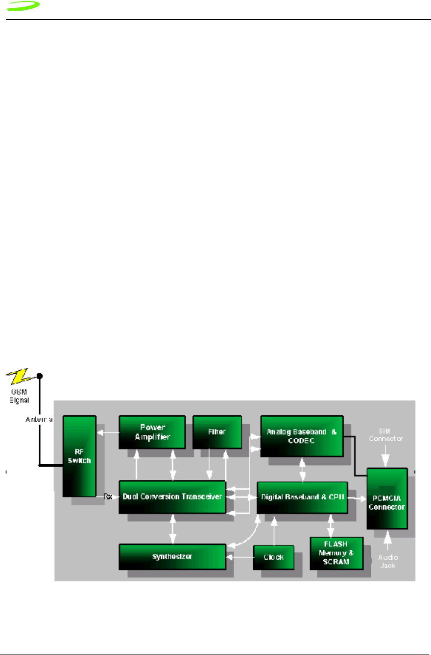
GSM Technology
GSM uses a time division multiplexing access method that permits up to eight users to
communicate using one frequency channel. The channel is broken up into eight time slots
with each slot operating independently, sending data between the network and the mobile
device.
Figure 1 GSM–Merlin Interface
Product Overview — Introduction to GSM and GPRS 3
P/N 9002363 Revision 1.9
GPRS (General Packet Radio Service) is a digital, packet-switched, data extension to the
GSM voice and circuit-switched data network. In short, it substitutes binary data for the
voice data, which is subsequently routed to a data network, the Internet, rather than the
public switched telephone network. This enables high-speed data communication on a
global wireless standard, using the same frequency bands as the underlying GSM
network.
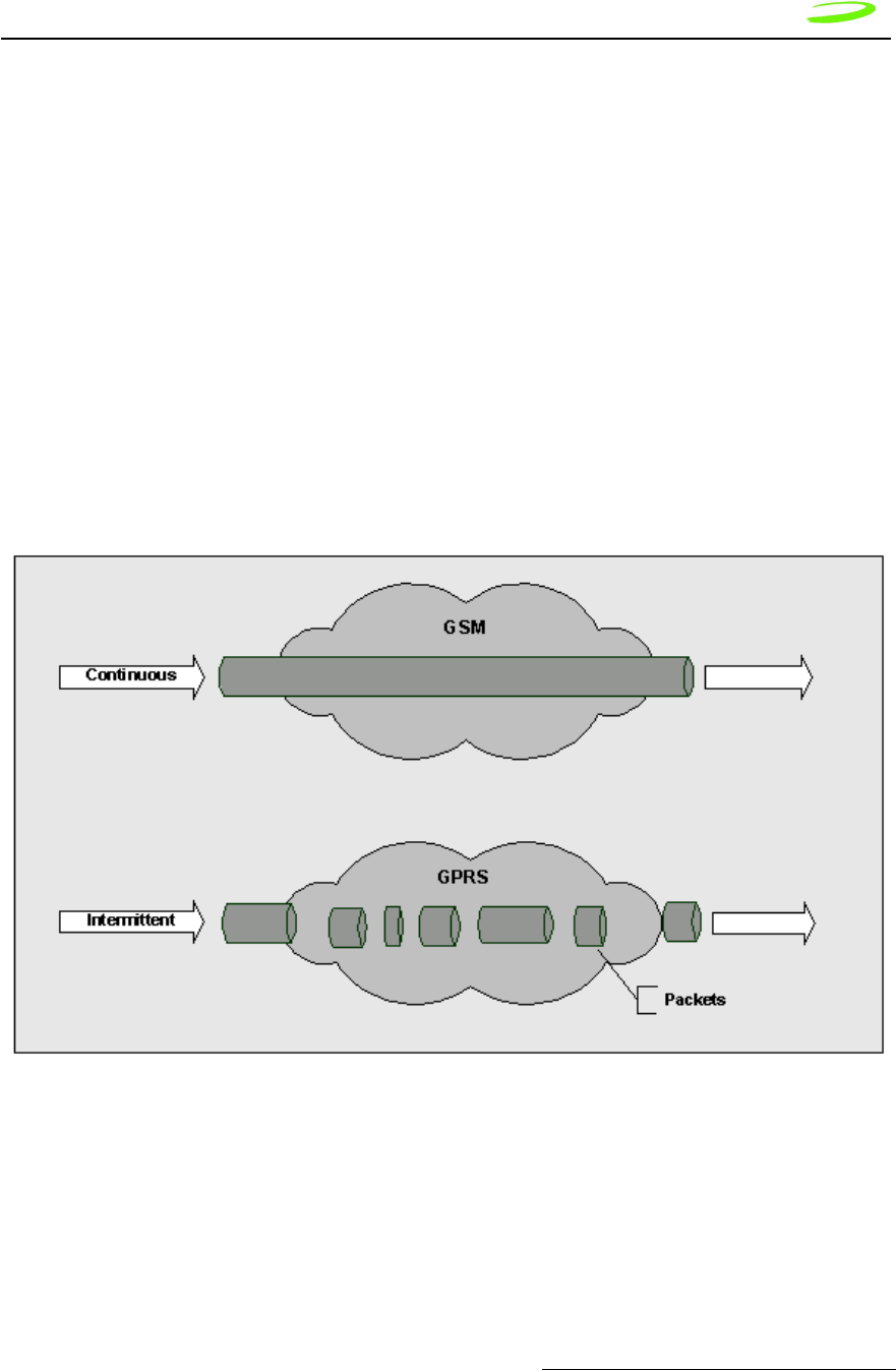
Advantages of GPRS
The advantage of a packet-based approach is that GPRS only uses the medium, in this
case the radio link, for the duration of time that data is being sent or received. GPRS has
one distinct advantage over the traditional GSM in that a channel is not dedicated to one
user. Communication channels are being used on a “shared-use as packets are needed”
basis rather than dedicated to one user at a time. This means that multiple users can
share the same radio channel. In contrast, with current circuit-switched connections,
users have dedicated connections during their entire call, whether they are sending data
or not. Many applications have idle periods during a session, with packet data, users will
only pay for the amount of data they actually communicate, and not the idle time.
Figure 2 GSM Vs. GPRS Data Transfer

4 Product Overview — Introduction to GSM and GPRS
Revision 1.9 P/N 9002363
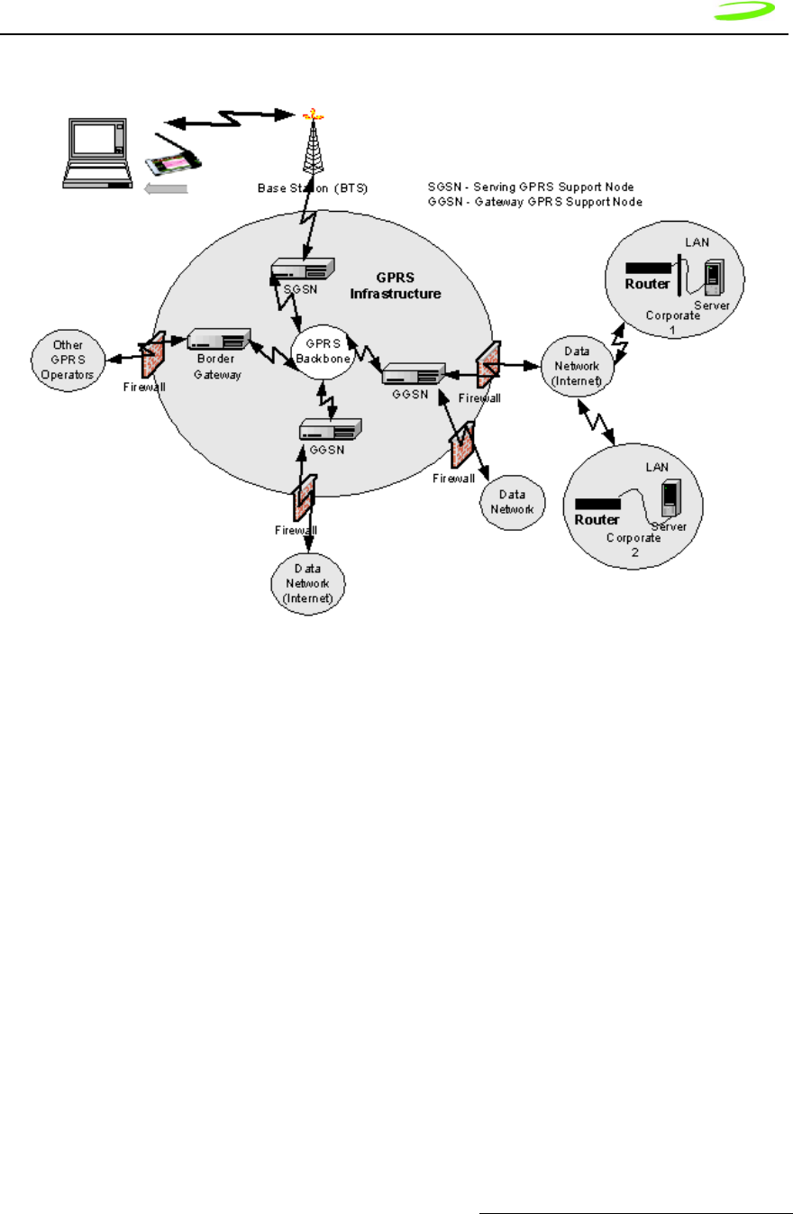
GPRS Network Architecture
To better understand GPRS, we take a quick tour beginning with the mobile PC and
traversing through the network. First, we have a notebook computer connected to a
GPRS-capable modem through a serial cable, Universal Serial Bus (USB), or PC Card.
The GPRS modem communicates with GSM base stations, but unlike circuit-switched
data calls that are connected to voice networks by the mobile switching center, GPRS
packets are sent from the base station (BTS) to what is called a Serving GPRS Support
Node (SGSN).
Enabling GPRS on a GSM network requires the addition of two core modules:
•Gateway GPRS Service Module (GGSN)
The GGSN acts as a gateway between the GPRS network and the Public Data
Networks such as IP. GGSN’s also connect to other GPRS networks to facilitate
GPRS roaming.
•Serving GPRS Support Node (SGSN)
The SGSN provides packet routing to and from the SGSN service node for all
users in that particular service area. It also keeps track of the mobiles within its
service area. The SGSN communicates with what is called the Gateway GPRS
Support Node (GGSN), a system that maintains connections with other networks
such as the Internet or private networks. A GPRS network can use multiple
serving nodes, but requires only one gateway node for connecting to an external
network such as the Internet.
When the mobile station sends packets of data, it is via the SGSN to the GGSN, which
converts them for transmission over the desired network, which could be the Internet
networks or private networks. IP packets from the internet addressed for the mobile
station are received by the GGSN, forwarded to the SGSN and then transmitted to the
mobile station.
To forward IP packets between each other, the SGSN and GGSN encapsulate these
packets using a specialized protocol called the GPRS tunnel protocol (GTP) which
operates over top of standard TCP/IP protocols. The details of the SGSN and GGSN are
both invisible and irrelevant to the user who simply experiences a straight forward IP
connection that just happens to be wireless. See Figure 3 GPRS Network Architecture
below for an illustrated display of the GPRS network.
Product Overview — Introduction to GSM and GPRS 5
P/N 9002363 Revision 1.9
Figure 3 GPRS Network Architecture
An interesting aspect of GPRS is how it achieves its high speeds to over 100 kbps when
circuit-switched data today is limited to 9600 (baud rate) or 14.4 kbps. GPRS uses the
same radio channel as voice calls, a channel that is 200 kHz wide. This radio channel
carries a raw digital radio stream of 271 kbps, which for voice calls is divided into 8
separate data streams, each carrying about 34 kbps. After protocol and error correction
13 kbps remains for each voice connection or about 14 kbps for data.
Circuit-switched data today uses one voice channel. GPRS can combine up to 8 of these
channels, and since each of these can deliver up to 14 kbps of data throughput, the net
result is that users will be able to enjoy rates over 100 Kbps. But not all eight-voice
channels have to be used. In fact, most mobile stations (MS) will be ones that are limited
to 56 kbps. The GPRS standard defines a mechanism by which a MS can request the
amount of bandwidth it desires at the time it establishes a data session.

6 Product Overview — Introduction to GSM and GPRS
Revision 1.9 P/N 9002363
Data Rates
Four major factors affect actual GPRS data rates:
•Multi-slot Class
Each timeslot can handle a given amount of data, established through
negotiation between the device and the network.
• Channel Coding Scheme
Four CS schemes are defined, each with a different level of error correction
(basically “overhead”, similar to CDPD, which takes the 19.2 down to a real
data rate somewhere between 10 and 12 kbps). As the amount of error
correction is reduced, the quantity of data in the packets increases, but the
probability that packets of data will need to be retransmitted increases.
Conversely, as the amount of error correction increases, less data can be sent
in each packet or timeslot, but the chance that re-transmission of packets is
required decreases. With no error correction, a maximum of 21.4 kbps per
channel can be supported - which, at the maximum 8 timeslots, equals 171.2
(for CS-4) kbps. At CS-1, there is 9.05 kbps per timeslot; this increases to
13.4 kbps per timeslot at CS-2 and 15.6 kbps per time slot at CS-3.
• Network Capacity
The device and the network will negotiate the appropriate combination of MS
class and CS scheme to determine the actual data, based on capabilities of
the device, and how busy the network is at a given point in time.
Because GPRS is an extension of the digital voice GSM network, voice calls
will always take priority over data calls (real time voice is more important than
data); therefore real data rates will, in many cases, be lower than the device
can support.
• Quality of Service (QoS)
There is the ability to assign a Quality of Service to a specific account. The
QoS is used to guarantee a certain data rate as well as capacity.
Most devices will be limited to MS-10, which, at CS-2, is a maximum of 53.6
kbps (4 * 13.4 = 53.6) Rx and 26.8 kbps (4 * 13.4) Rx, or nominally 56 and 28.
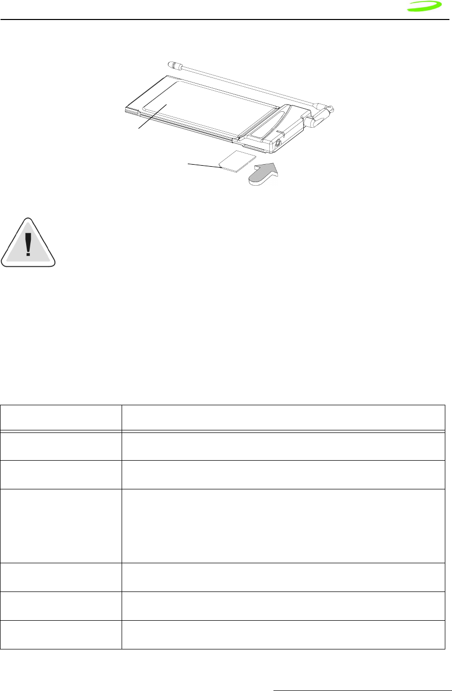
SIM
GPRS requires a unique SIM (Subscriber Identity Module) card for each device. The SIM
Card identifies individual users to the network for billing and other purposes, ensures a
common set of SIM-based features, and maintains security with other GSM devices.
Product Overview — Operational Features 7
P/N 9002363 Revision 1.9
A SIM card must be present in the device at all times to allow network access.
A SIM card is required for all PC Card functions except emergency calls.
SIM cards can be moved from one device to another without the need to inform the
network carrier. SIM cards may be configured differently to support different modes of
operation.
Operational Features
Table 2: Summary of Operational Features
Feature Description
Class of Operation Class B: Modem supports both GSM CSD and GPRS Packet data, but will not support
both simultaneously
GSM Circuit Switched Data
(CSD)
Transparent and non-transparent CSD over GSM networks up to 14.4kbps
General Packet Data Service
(GPRS)
• MS-10 operation
• Type 1 device (Simplex RF operation)
• up to 4 receive slots, up to 2 transmit slots, for a combined maximum of 5 slots
• 4/1, 3/1,3/2,2/2, 2/1 combination provides theoretical rates of up to 56 kbps
receive and 28 kbps transmit
• automatically maintains GPRS virtual circuit when CSD or Voice traffic is present
SMS (Short Messaging Ser-
vice)
Mobile originated and mobile terminated SMS messages.
Voice (May not be supported
on all devices)
Supports voice communication using any differential headset.
AT Commands Standard GSM AT Command set with enhancements (See Chapter 3: AT Com-
mands).
SIM card
Merlin modem

8 Product Overview — Notices
Revision 1.9 P/N 9002363
Notices
Safety Warning
Neither Merlin or Expedite GPRS products may be used in an environment where radio
frequency equipment is prohibited or restricted in its use. This includes aircraft/airports,
hospitals, and other sensitive electronic areas. To ensure that the modem is deactivated
remove it from the computer under the above conditions.
Under extended operation the Merlin modem will generate a noticeable amount of heat.
Like all PC Cards, the modem generates heat during normal operation and will be heated
by the host computer. For this reason it is recommended that after extended periods of
operation, prior to removal and handling, the user allow the modem to cool down.
Software Interface • standard GSM AT Command set with enhancements
• supports PPP protocols for external hosting
• supports channel coding schemes CS-1 and CS-2
Software included • Compatible with Windows 98SE/ME/2000/XP, Windows NT 4.0 SP4, Pocket PC
3.0 and Pocket PC 2002
Approvals • Full Type Approval, compliant to GSM Phase 2+ standard (all)
• FCC Part 15 and Part 24 (PCS1900) (Merlin G100, G301, Expedite G301)
• Essential requirements of the Radio and Telecommunications Terminal
Equipment (R&TTE) Directive, 1999/5/EC; 3GPP TS 51.010-1 Digital Cellular
Telecommunications SYstem (Phase 2+) Mobile Station (MS) conformance
Specification; Part 1: Conformance Specification (Merlin G201,G301)
Frequency Band • PCS 1900 North American GSM (Merlin G100) or
• GSM 900 / DCS 1800 (Merlin G200 series) or
• GSM 900 / PCS 1900 / DCS 1800 (Merlin G301 and Expedite G301)
Data Power Connector • standard 16 bit PCMCIA PC Card Interface
• 70 pin electrical interface for Expedite
SIM Card • SIM card supplied by the carrier as a separate item. Expedite provides connection
signals for an external SIM Module
Antenna Interface • standard 50-ohm MMCX antenna termination (Expedite G301, Merlin G201)
• standard 50-ohm Radial MC card type antenna connector (Merlin G100)
Output Power Level • GSM Power Class 1 at DCS 1800 and PCS 1900 frequency bands.
• GSM Power Class 4 at GSM 900 frequency bands
Temperature • Operating -10oC to +55 oC
• Storage -30oC to +75 oC
Power Supply • nominal 3.6 volt DC supply for Expedite module
Feature Description

Product Overview — Notices 9
P/N 9002363 Revision 1.9
FCC RF Interference Statement
Federal Communications Commission Radio Frequency Interference Statement.
This equipment has been certified to comply within the limits of a class B digital device
pursuant to part 15 and Part 24 of the FCC Rules. These limits are designed to provide
reasonable protection against harmful interference in residential situations. This
equipment generates, uses, and can radiate radio frequency energy, and, if not properly
installed and used in accordance with the instructions, may cause harmful interference to
radio or television reception, or to laptop computers and PDAs. This can be determined
by turning the equipment on and off. The user is encouraged to try to correct the
interference by one or more of the following measures:
• Reorient or relocate the receiving antenna of the television, radio or cordless
telephone.
• Increase the separation between the equipment and the receiver.
• Connect the equipment to an outlet on a circuit different from that to which the
receiver is connected.
• Consult the dealer or an experienced radio/television technician for additional
suggestions
This device complies with part 15 of the FCC Rules. Operation is subject to the following
two conditions: (1) This device may not cause harmful interference, and (2) this device
must accept any interference received, including interference that may cause undesired
operation.
Regulatory Requirements
The regulatory requirements for the embedded module may include the following,
depending on the market where the module will be sold.
United States of America
FCC CFR47 Part 2 (General Rules and Regulations, RF Exposure Evaluation)
FCC CFR47 Part 15 (All Radio Frequency Devices)
FCC CFR47 Part 24 (Narrow and wideband PCS modules)
Canada
Industry Canada RSS-118 (Cellular Band)
Industry Canada RSS-102 (RF Exposure)
Industry Canada RSS-133 (2GHz PCS band)
Europe and Asia
Radio and Telecommunications Terminal Equipment (R&TTE) Directive, 1999/5/EC.”
Mobile Station (MS) Conformance Specification Part 1:3GPP TS 51.010-1.
Harmonized Radio Standard ETSI EN 301 511 V.7.0.1

10 Product Overview — Notices
Revision 1.9 P/N 9002363
Additional regulatory information for Asia will be made available in future versions of this
document.
Radio Frequency Exposure Evaluation Requirements
For applications that provide a separation of at least 20 cm from the radiating element to
the users and bystanders in the United States market, the embedded modules are treated
as “mobile devices” as per FCC CFR47 paragraph 2.1091.
A mobile device is defined as “a transmitting device designed to be used in other than
fixed locations and to generally be used in such a way that a separation distance of at
least 20 cm is normally maintained between the transmitter’s radiating structure(s) and
the body of the user or nearby persons.” The antenna type used for the radio frequency
exposure evaluation must be specified in the documentation and sold with the module. If
the module is used with a different antenna type and/or in a design where the separation
distance of 20 cm is not normally maintained, the radio frequency exposure evaluation
should be repeated for the new configuration. Use of this device in applications that
would not ensure the 20 cm minimum separation are in violation of the FCC quthorization
for this device. A new FCC application and authorization would be required for use at
less than 20 cm separation.
Some devices are not subject to radio frequency exposure evaluation prior to
equipment authorization, depending on the transmitter power level and
frequency band of operation.
Regulation and Compliance
The Merlin G100 conforms to ETSI EN 300 607-1 for the digital cellular
telecommunications system (Phase 2+) mobile station conformance specification, Part 1
Conformance Specification.
Merlin G200 Declaration of Conformity
The Merlin G200 Series (G200, G201) conforms to the essential requirements of the
Council Directive 1999/5/EC of the European Parliament and the Council on the basis of
Technical Construction. File titled “Merlin G200/G201” in relation to the essential
requirements of Article 3.2 of the Directive.
Technical Support Contacts
To obtain technical support for a Merlin GPRS PC Card, please contact the provider of
your GPRS SIM card, your local GSM/GPRS service operator, or the supplier of your
Merlin GPRS PC Card. Where local support is not available, contact the Novatel Wireless
Technical Support Team.
WWW: www.nvtl.com/support/index.htm
Email: gprs_support@nvtl.com
To obtain technical support for an Expedite GPRS OEM module, please contact your
NVTL sales agent to arrange a direct support contact.

Product Overview — Notices 11
P/N 9002363 Revision 1.9
Limited Warranty and Liability
Hardware Warranty
Novatel Wireless™ warrants that during the Warranty Period that:
1. the Product will be free from defects in material and workmanship under
normal use and service and will conform to Novatel Wireless’s (Novatel
Wireless Technologies™) specifications
2. the software will be free from error that materially affect performance
Products
One (1) year
Accessories
90 days (in each case from the date sold by Purchaser)
These warranties are expressly written in lieu of all other warranties, either expressed or
implied, including, without limitation, all implied warranties of merchantability and fitness
for a particular purpose. Novatel Wireless™ liability hereunder is expressly limited to
refund of all amounts paid to Novatel Wireless™ for any defective units or products,
whether Novatel Wireless™ liability arises from breach of warranty, or with respect to any
obligation arising from breach of warranty, or otherwise with respect to the manufacture
and sale of any units of the product, whether liability is asserted in contract or tort,
including negligence and strict product liability. Novatel Wireless™ shall in no event be
liable for special, indirect, incidental, or consequential damages of any kind or nature due
to any cause.
Purchaser’s exclusive remedy for a claim under this warranty shall be limited to the repair
or replacement, at Novatel Wireless™’s option, of defective or nonconforming materials,
parts or components.
The foregoing warranties do not extend to the following:
• nonconformities, defects or errors in the Products due to accident, abuse,
misuse or negligent use of the Products or use in other than a normal and
customary manner, environmental conditions not conforming to Novatel
Wireless™’s specifications, or failure to follow prescribed installation,
operating and maintenance procedures
• defects, errors or nonconformities in the Products due to modifications,
alterations, additions or changes not made in accordance with Novatel
Wireless™’s specifications or authorized by Novatel Wireless™
• normal wear and tear
• damage caused by force of nature or act of any third person, (v) shipping
damage
• service or repair of Product by the Purchaser without prior written consent
from Novatel Wireless™

12 Product Overview — Notices
Revision 1.9 P/N 9002363
• products designated by Novatel Wireless™ as beta site test samples,
experimental, developmental, preproduction, sample, incomplete or out of
specification Products
• returned Products if the original identification marks have been removed or
altered
Software Warranty
Novatel Wireless™ warrants that for a period of 12 months from delivery at the FCA
point, that the Products are free from defects in material and workmanship, conform to
Novatel Wireless™ specifications and the software is free from errors which materially
affect performance. This warranty is exclusive and Novatel Wireless™ makes no
representation or warranty of any other kind, express or implied, with respect to its
products, whether as to merchantability, fitness for a particular purpose or any other
matter. The foregoing warranty does not extend to (i) non-conformities, defects or errors
in the Products due to accident, abuse, misuse or negligent use of the Products or use in
other than a normal or customary manner, environmental conditions not conforming to
Novatel Wireless™’s specifications, or failure to follow prescribed operating and/or
maintenance procedures; (ii) defects, errors or non-conformity in the Products due to
modifications, alterations, additions, or changes not made or authorized to be made by
Novatel Wireless™; (iii) normal wear and tear; or (iv) damage caused by force of nature
or act of any third party.
•Novatel Wireless™’s obligations are limited to correction of a failure or defect in
the Products by implementation of a module swap whenever practicable. Novatel
Wireless™ does not warrant that the execution of the software shall be
uninterrupted or error free.
•In the event of a warranty claim, the Purchaser shall return the Products to Novatel
Wireless™’s Calgary facility for testing and examination at the Purchaser’s
expense. After testing and examination Novatel Wireless™ shall either:
•determine the claim is a valid warranty claim in which case the Products
will be repaired and returned to the Purchaser at Novatel Wireless™’s cost
and the Purchaser shall be reimbursed for the original cost of shipping the
Products to Novatel Wireless™ to evaluate the warranty claim
or
• determine the claim is not valid or that the warranty has been voided in
which case the Products shall be returned to the Purchaser at the
Purchaser’s cost
•Purchaser’s exclusive remedy for claims arising hereunder shall be for damages.
Novatel Wireless™’s liability for any and all losses and damages to purchaser
resulting from any cause whatsoever including Novatel Wireless™’s negligence or
alleged damage or defective products, irrespective of whether such defects are
discoverable or latent, shall in no event exceed the purchase price of the particular
products with respect to which losses or damages are claimed, or at Novatel
Wireless™’s election, the repair or replacement of defective or damaged products
or the issuance of a credit memo in lieu thereof. In no event, including in the case
of a claim of negligence, shall Novatel Wireless™ be liable for incidental or
consequential damages.

Product Overview — Notices 13
P/N 9002363 Revision 1.9
Novatel Wireless™ may, at its discretion, implement changes in the Products, modify the
drawings and its specifications for the Products, or substitute product of more recent
design; provided, however, that any such changes, modifications or substitutions, under
normal and proper use shall not materially and adversely affect functional performance,
form or fit of the Products. Novatel Wireless™ agrees to use reasonable efforts to provide
the Purchaser with 30 days written notice of such changes.
Version Compatibility
Novatel Wireless™ will make all efforts to ensure that firmware upgrades are backwards
compatible with earlier versions of both firmware and hardware. Hardware revisions
introduced must be used with factory loaded firmware or a compatible version of a later
release. At no time will Novatel Wireless™ warrant a device which is loaded with a
firmware version which predates the devices hardware revision date.
Validity of Warranty Claim
The validity of any warranty claim shall be subject to, and conditional upon confirmation
by Novatel Wireless™ within 30 days from receipt of such claim. Postage, freight or other
such transportation charges for shipping parts subject to the warranty claim to an
authorized Novatel Wireless™ repair facility shall be borne by Purchaser. The Purchaser
agrees to pay an additional $40/unit to cover the cost testing and handling for any unit
submitted which is determined by Novatel Wireless™ to be invalid claim. Novatel
Wireless™ shall bear the cost of postage, freight or other such transportation charges for
the return to Purchaser provided the warranty claim is determined by Novatel Wireless™
to be a valid claim. Any unit repaired or replaced under warranty shall be warranted only
for the balance of the warranty period already in effect for the original item or if the
balance of the warranty period is less than 90 days, the warranty shall be for 90 days from
the date of repair or replacement.
Care, Repair and Return
The following criteria must be met prior to returning products to Novatel Wireless Inc™.:
•Contact our Technical Support team to obtain a Return Material Authorization
(RMA) number. An RMA number is valid for 15 business days and must be received
within those 15 days.
The following information must be provided:
•IMEI or serial number
•reason for return
•original invoice (if possible)
•user name, phone number, email address
•charging information
•Returns on defective products are not subject to the 15% restocking fee. The
product defect must be verified by the Novatel Wireless™ Technical Support staff
before a replacement unit or refund is issued.
•Defective products that are returned outside of the 30 day period, but still covered
by Novatel Wireless™ Limited Warranty will either be repaired or replaced. No
refund is issued on these units.

14 Product Overview — Notices
Revision 1.9 P/N 9002363
•Returns on defective products that are no longer covered by the Novatel Wireless™
Limited Warranty will be subject to a repair fee. Please contact our Technical
Support staff for more information.
•Returns on opened, non-defective product are subject to a 15% restocking fee. All
items must be in “as new” condition, in the original packaging and include all
warranty cards, documentation and software. Should any items be missing the user
will be billed or a portion of the refund will be deducted.
•There will be a $15.00 repackaging fee for products not returned in the original
packaging. The user is responsible for shipping costs on all returns.
•There are no returns for credit on product accessories.
Mailing Address
Novatel Wireless, Inc™.
9360 Towne Centre Drive, Suite 110
San Diego, CA 92121-3030
Icon Usage
Throughout this manual icons are used to signify information that may require special
attention. The icons are as follows:
Note: Signifies an item that may be noted and used in more then one
situation.
Hint: Signifies a time saver or a specific function that must be performed in
order to experience success. May also indicate that a shortcut may be used.
Reference Material: Other sources of information exist and may be referred
to.
Warning: Performing a specific function may cause an operation to fail,
subsequently losing information or affecting system performance.

M
M
M
Me
e
e
er
r
r
rl
l
l
li
i
i
in
n
n
n
a
a
a
an
n
n
nd
d
d
d
E
E
E
Ex
x
x
xp
p
p
pe
e
e
ed
d
d
di
i
i
it
t
t
te
e
e
e
Chapter 2:
Specifications
This section contains specifications for Merlin G100 and G200 GPRS PC Card
modems and the Expedite G301 OEM modem module.
Merlin GPRS PC Card Specifications
The Merlin G100 and G200 are wireless modems designed to be plugged into
the PC Card slot of a host computer.
Topics Included in this Chapter
Merlin GPRS PC Card Specifications . . . . . . . . . . . . . . . . . . . . . . . . . . . . . 15
Expedite G301 OEM Module Specifications . . . . . . . . . . . . . . . . . . . . . . . . 24
Air Interface . . . . . . . . . . . . . . . . . . . . . . . . . . . . . . . . . . . . . . . . . . . . . . . 38
Subscriber Identification Module (SIM) . . . . . . . . . . . . . . . . . . . . . . . . . . . . 39
Modes of Operation . . . . . . . . . . . . . . . . . . . . . . . . . . . . . . . . . . . . . . . . . . 40
Application Information . . . . . . . . . . . . . . . . . . . . . . . . . . . . . . . . . . . . . . . 41

16 Specifications Merlin GPRS PC Card Specifications
Revision 1.9 P/N 90023363
Merlin General Specifications
Table 3: General Specification for Merlin GPRS PC Cards
Physical Dimensions
and Weight Merlin G100 Merlin G200
Length
Total 111.64 mm 111.71mm
Width
Without Antenna 54.0 mm 54.0 mm
With Antenna 60.63 mm
Thickness
Insertion Thickness 5.60 mm 5.60 mm
Exposed Thickness 7.68 mm 8.96 mm
Weight
Complete Modem (unpackaged) 49.1 gm 51.0 gm
Temperature
Temperature Range Operating -10oC to 55 oC
Storage -30oC to 75oC
Relative Humidity
Maximum operating humidity at 50oC (non-
condensing)
up to 95% Non-condensing
Recommended Operating Conditions
Maximum Supply Input Voltage 5.25 v
Minimum Supply Input Voltage 4.75 v
Recommended Supply Voltage 5 v
Supply Voltage Range 4.75 to 5.25 v DC
Moisture and Dust Resistance
Do not immerse or expose to excessive moisture. The case is not to be con-
sidered dustproof.
Thermal Shock Merlin G100 Merlin G200
Non-Operating -50 oC to +20 oC, +70 oC to
+20 oC; less than 5 min
-200C to 550C

Specifications Merlin GPRS PC Card Specifications 17
P/N 90023363 Revision 1.9
Vibration
Sinusoidal 3.0 mm displacement, 2 to 9
Hz; 1 m/s2, 9 to 350 Hz
147 m/s2, 15g peak ampli-
tude, 10Hz-2000 Hz
Random 0.1 m2 /s3, 2 to 200 Hz 0.96 m2/s3, 5 Hz-20Hz, -
3db/0ct, 20 Hz-500Hz
Transport Packaged ASTM D999 N/A
Mechanical Shock N/A semi sine 50 g 11ms
Emissions
Electromagnetic Emissions Radiated spurious FCC part
24 / Part 15 Class \ BGSM
11.10 Section 12.2EN 55022
Class B
EMC: ETSI EN 301489-1
Electromagnetic Immunity As per ETSI ETS 300 342-1 N/A
Electrostatic Discharge (ESD) for PC Con-
nector
To Contacts 2 KV
To Antenna Port 8 KV
To Case 10 KV
ESD IEC 61000-4-2
To contacts: 8kv
To antenna port: 8kv
To audio jack: 8kv
To case: 8kv
Transmit Power
GSM Power Class 1
GSM Power Class 4
• DCS 1800 / PCS1900
• GSM 900
Connectors
Antenna RADIALL SMT microminia-
ture 50 ohm coaxial connec-
tor
(PN R199-005801)
HUBER + SUHNER SMT
MMCX 50 ohm coaxial
connector (PN 82 MMCX -
S50-0-2)
Audio No audio jack HOSIDEN audio jack (PN
HSJ1816-019010)
PC Card Connector ITT CANNON 68 pin con-
nector (PN 127040-2414
5925)
ITT CANNON 68 pin con-
nector (PN 127040-2414
5925)
SIM Connector ITT CANNON
(PN CCM04)
JAE SIM Socket (PN SF
2W006S4KE3000)
18 Specifications Merlin GPRS PC Card Specifications
Revision 1.9 P/N 90023363
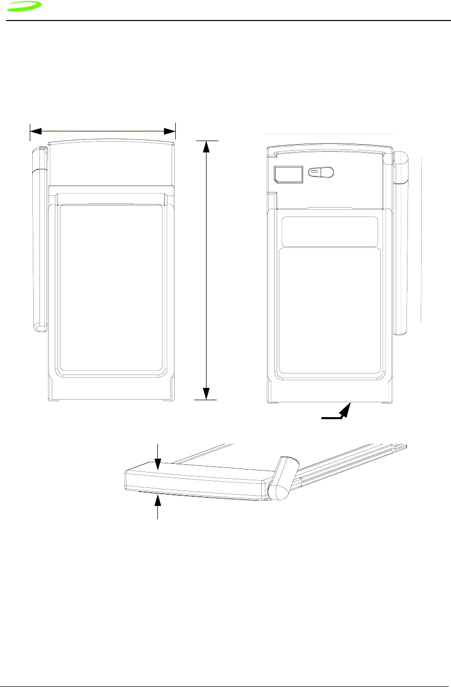
Merlin Physical Appearance
Merlin G100.
Figure 1: Mechanical View of MerlinG100
Front View Back View
60.63
Side View
7.68
68-Pin Connector
Specifications Merlin GPRS PC Card Specifications 19
P/N 90023363 Revision 1.9
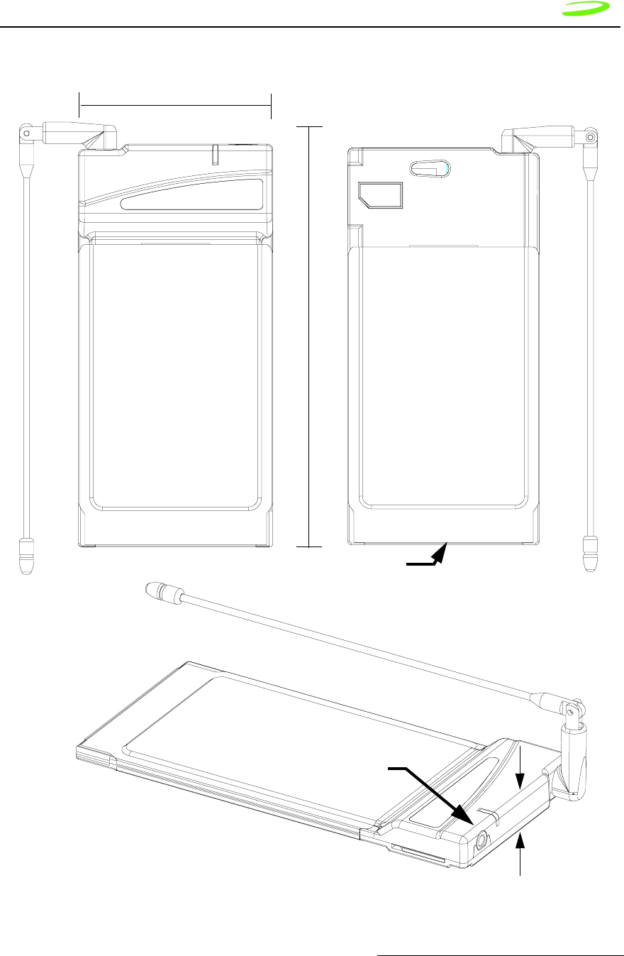
Merlin G200
Figure 2: Mechanical View of Merlin G200 Series
Front View Back View
Side View 8.96
54.00
Audio
Jack (G201
68-Pin Connector
only)

20 Specifications Merlin GPRS PC Card Specifications
Revision 1.9 P/N 90023363
PC Card Connector Pin Assignment
Ta b l e 4 below contains the pinout information of the 68-pin Merlin PC Card connector.
Table 4: Merlin GPRS PC Card Pin Assignment
Pin # Signal Name Direction
1GND Power
2 D3 Supported
3 D4 Supported
4 D5 Supported
5 D6 Supported
6 D7 Supported
7 CE#1 Supported
8 A10 Not Connected
9 OE# Supported
10 A11 Not Connected
11 A9 Supported
12 A8 Supported
13 A13 Not Connected
14 A14 Not Connected
15 WE# Supported
16 IREQ# Supported
17 VCC Card is configured as a 5V card.
18 VPP1 Not Connected
19 A16 Not Connected
20 A15 Not Connected
21 A12 Not Connected
22 A7 Supported
23 A6 Supported
24 A5 Supported
25 A4 Supported
26 A3 Supported
27 A2 Supported
28 A1 Supported
29 A0 Supported

Specifications Merlin GPRS PC Card Specifications 21
P/N 90023363 Revision 1.9
30 D0 Supported
31 D1 Supported
32 D2 Supported
33 IOIS16# Pulled High
34 GND Power
35 GND Power
36 CD#1 Connected to Card Ground
37 D11 Not Connected
38 D12 Not Connected
39 D13 Not Connected
40 D14 Not Connected
41 D15 Not Connected
42 CE2# Supported
43 VS1# Not Connected (SELECTS VCC = 5V FOR CARD)
44 IORD# Supported
45 IOWR# Supported
46 A17 Not Connected
47 A18 Not Connected
48 A19 Not Connected
49 A20 Not Connected
50 A21 Not Connected
51 VCC POWER, Card is configured as a 5V card
52 VPP2 Not Connected
53 A22 Not Connected
54 A23 Not Connected
55 A24 Not Connected
56 A25 Not Connected
57 VS2# Not Connected (SELECTS VCC = 5V FOR CARD)
58 RESET Supported
59 WAIT# Supported
60 INPACK# Pulled High
61 REG# Supported
62 BVD2/SPKR# Pulled High, No Audio
63 BVD1/STSCHG# Pulled High
22 Specifications Merlin GPRS PC Card Specifications
Revision 1.9 P/N 90023363
Interfaces
Merlin Hardware Interface
The modem is electronically configured as a 5-Volt 8-bit I/O memory card. The supported
pins on the 68 position interface connector are driven by a LVTTL interface IC that
includes 5V tolerant inputs and runs off a 3.1V power supply. Signals driven by this card
will reach 3.1V but can accept 5V logic levels on inputs.
Air Interface
Table 5: Air Interface Data Rates
Table 6: Radio Channel Frequency
64 D8 Not Connected
65 D9 Not Connected
66 D10 Not Connected
67 CD2# Connected To Card Ground
68 GND Connected To Card Ground
Coding
Scheme
Data Rates per Time Slot
(Kbps)
Maximum Data Rate (8
Time Slots)
CS1 9.05 72.4
CS2 13.4 107.2
Radio Channel Frequency
Bands Channel Tx Rx
P-GSM 900 1 < n < 124 Freq(n)=890+0.2*n Freq(n)=935+0.2*n
E-GSM 900 0 < n < 124
975 < n < 1023
Freq(n)=890+0.2*n
Freq(n)=890+0.2*(n-1024)
Freq(n)=935+0.2*n
Freq(n)=935+0.2*(n-1024)
DCS 1800 512 < n < 885 Freq(n)=1710.2+0.2*(n-512) Freq(n)=1805.2+0.2*(n-512)
PCS 1900 512 < n < 810 Freq(n)=1850.2+0.2*(n-512) Freq(n)=1930.2+0.2*(n-512)
Specifications Merlin GPRS PC Card Specifications 23
P/N 90023363 Revision 1.9
Table 7: Radio Power Index
Table 8: PCS Gain Index
Modes
The Merlin GPRS PCS PC Card supports both memory mode and I/O mode.
Memory Mode
When the Merlin GPRS PCS PC Card is inserted into a PC card host, the card will power
up in memory mode. In this mode, the host will read CIS from the attribute memory on the
card and then configure the card for I/O mode and assign the card a COM port. This
process is automatic and transparent to the user.
The Merlin GPRS PCS PC Card does not provide the host with any additional
RAM or FLASH storage.
I/O Mode
Once the GPRS PCS PC Card has been configured and the COM port assigned, the card
will then be in 8-bit I/O mode. The information that the host will read from CIS memory will
indicate that the device is a modem card with a serial port interface containing a UART
type of 16550. The combination of the base addresses and IRQs, in the order that the
modem will accept, are listed below in Table 9: Base Addresses and IRQs.
Table 9: Base Addresses and IRQs
Radio Power Index
Bands Index Power
GSM 900 5-19 2dB Incremental steps
PCS 1900/DCS 1800 0-15 2dB Incremental steps
0 - 25 0 = min gain, 25 = max gain
Base Address IRQ Comment
3F8 4 Only level interrupts are supported
2F8 3 Only level interrupts are supported
3E8 4 Only level interrupts are supported
2E8 3 Only level interrupts are supported
Any base address 7- 0 and 15 - 8 Only level interrupts are supported

24 Specifications Expedite G301 OEM Module Specifications
Revision 1.9 P/N 90023363
Expedite G301 OEM Module
Specifications
The Expedite G301 is a tri-band GSM/GPRS radio module designed to be integrated by
third party developers into a finished product.
Expedite General Specifications
Table 10: Technical Specification for Expedite G301 Module
Physical Dimension and Weight Specifications
Length 50.0 ± 0.30 mm
Width 37.0 ± 0.30 mm
Thickness 5.0 mm (maximum)
Temperature
Temperature Range Operating -100C to +600C
Storage -30oC to 75oC
Relative Humidity
Maximum operating humidity at 50oC (non-condensing) Up to 95% Non-condensing
Recommended Operating Conditions
Maximum Supply Input Voltage 4.5 V
Minimum Supply Input Voltage 3.4 V
Supply Voltage Range 3.4 to 4.5 VDC
Moisture and Dust Resistance
Do not immerse or expose to excessive moisture. The case is not to be considered dust proof.
Vibration
Sinusoidal 3.0 mm displacement, 2 to 9 Hz; 1 m/s2, 9
to 350 Hz
Random 0.1 m2 /s3, 2 to 200 Hz
Transport Packaged ASTM D999
Emissions
Electromagnetic Emissions Meets radiated spurious FCC part 24 /
Part 15 Class \ BGSM 11.10 Section
12.2EN 55022 Class B
Specifications Expedite G301 OEM Module Specifications 25
P/N 90023363 Revision 1.9
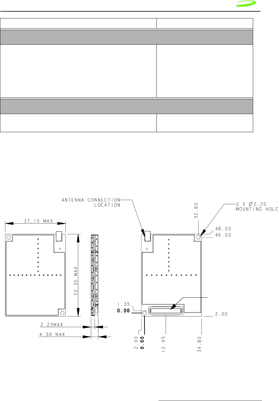
Expedite Physical Appearance
Figure 3 Expedite G301 Mechanical Dimensions
Electromagnetic Immunity As per ETSI ETS 300 342-1
Data Rates
Host Interface Baud Rate The module supports as a minimum, asyn-
chronous data transmission of the follow-
ing rate and format:
Baud Rate: 9600, 19200, 57600, 115200
Data Bits: 8
Parity: None
Stop Bits: 1
Transmit Power
GSM Power Class 1
GSM Power Class 4
• DCS 1800 / PCS1900
• GSM 900
70-pin Baseband
Connector

26 Specifications Expedite G301 OEM Module Specifications
Revision 1.9 P/N 90023363
Interfaces
Expedite Host Interface Signals
The Expedite interfaces to a host via a 70 pin baseband connector. Table 11 describes
the signals on the connector.
Table 11: Expedite Host Interface Signals
Signal Pin Description Direction
GND 6, 9, 14, 15,
16, 17, 26, 27,
42, 60, 61, 66
Ground SUPPLY
VCC 28, 29, 30, 31 Power Supply (except Power Amplifier) SUPPLY
VBAT_PA 18, 19, 20, 21,
22, 23, 24, 25
Power Amplifier Supply SUPPLY
MDM_RDY 59 Indicates to host that Modem is ready to communicate OUT
PWR_ON 58 Dual Function pin. Used to turn modem on (and off in
the second mode).
IN
SM_IND 57 Sleep Mode Indicator. A high signal indicates that the
modem is in sleep mode.
OUT
WAKE_UP 63 An edge triggered interrupt pin to wake up the modem
from sleep mode.
IN
PUL_PWREN 69 Pulse-Power-Enable. Selects between pulse mode
modem turn on and solid mode turn on. A high on this
pin will select pulse mode.
IN
RESET_N 70 Active low input to perform a hardware reset on the
modem. Internally pulled up on Modem.
IN
TX_STAT 68 Transmit status. Active high signal indicating to host
that the modem’s radio is transmitting.
OUT
DTM 56 Data To Modem. Asynchronous serial data to modem. IN
DFM 55 Data From Modem. Asynchronous serial data from
modem.
OUT
DTR 54 Data Terminal Ready. Active High signal indicating to
the modem that the host terminal is active.
IN
DSR 53 Data Set Ready. Active high signal indicating to the
host that the modem terminal is active.
OUT
CTS 52 Clear To Send. Active high signal indicating to the host
that the modem can receive characters.
OUT
RTS 51 Ready To Send. Active high signal indicating to the
modem that the host can receive characters.
IN
GPIO1 49 General Purpose Input/Output 1 BiDir
GPIO2 50 General Purpose Input/Output 2 BiDir
GPIO3 47 General Purpose Input/Output 3 BiDir

Specifications Expedite G301 OEM Module Specifications 27
P/N 90023363 Revision 1.9
Modem Power-On and Wake up Strategy
The Expedite G301 is designed so that the host has full control of powering up and
powering down the unit, both by hardware and software. There are two schemes available
to perform this function to accommodate different host preferences.
The first mode is called “pulsed power-on” and is selected by the host holding the
PUL_PWREN signal high. Note that there is an internal 47kΩ pull-up resistor to 2.5V on
this signal and it can be left unconnected on the host side. The second mode is called
“solid power-on” and is selected by the host holding the PUL_PWREN signal low.
GPIO4 46 General Purpose Input/Output 4 BiDir
GPIO5 45 General Purpose Input/Output 5 BiDir
GPIO6 44 General Purpose Input/Output 6 BiDir
ADC_IN_1 5Analog to Digital Converter. The modem can monitor a
voltage on this pin.
IN
VCC_SIM 36 Subscriber Identity Module Supply. Used to supply the
power to an off-board SIM.
SUPPLY
DATA_SIM 34 SIM data line. BiDir
RST_SIM 39 SIM reset line. OUT
CLK_SIM 32 SIM clock line. OUT
SIM_IN 33 SIM detect line. Active high signal indicating to the
modem that a SIM is present
IN
MIC_INP 2Differential Microphone Input (+) for voice communi-
cations.
IN
MIC_INN 4Differential Microphone Input (-) for voice communica-
tions.
IN
SPKR_OUTP 3Differential Speaker Output (+) for voice communica-
tions.
OUT
SPKR_OUTN 1Differential Speaker Output (-) for voice communica-
tions.
OUT
BUZZER 8Buzzer control signal from modem. OUT
RTS_2 38 Ready to Send for the secondary serial port on the
modem.
IN
DFM_2 43 Data to Modem for the secondary serial port on the
modem.
OUT
DTM_2 40 Data from Modem for the secondary serial port on the
modem.
IN
CTS_2 41 Clear to Send for the secondary serial port on the
modem.
OUT
Pins numbers not mentioned in the table should be left unconnected.

28 Specifications Expedite G301 OEM Module Specifications
Revision 1.9 P/N 90023363
There is also a WAKE_UP signal which is used to wake the modem up from a sleep state.
This signal is rising edge interrupt triggered. The host can determine if the modem is in
sleep mode by polling the SM_IND signal which will be asserted high when the modem is
asleep.
The MDM_RDY signal is asserted high when the modem is capable of communicating
with the host. MDM_RDY should always be used by the host to enable buffers that are
used for inputs to the modem. In the event that MDM_RDY is deasserted, the modem is
not capable of sending or receiving data on either of it’s serial ports.
A description of each power on mode is given below.
Pulsed Power-On
With the PUL_PWREN pin in a high state, the modem must be powered on by providing
an active high pulse of minimum 600mS to the PWR_ON pin. Once MDM_RDY goes high,
PWR_ON can drop and the modem will stay on.
This mode of operation will allow the modem to be shut down by a software AT command
(ATH4). When the command is issued, the processor will deregister from the network and
perform any power down activities required and then will drive MDM_RDY low before
powering off.
Solid Power-On
With the PUL_PWREN pin in a low state, and the PWR_ON signal is driven high, the
modem will turn on. The PWR_ON signal must remain high to keep the modem on.
This mode of operation will not permit a software shutdown.
If the modem is to be operated with this method, care must be taken to perform the
necessary network activities (eg. De-registration) before shutting the modem off.
Serial Ports
The Expedite module has two serial ports (primary and secondary) used to communicate
with the host and other peripheral devices. The primary serial port consists of the DTR,
DSR, RTS, CTS, DTM, and DFM signals. It operates at baud rates of 9600 to 115200, has
8 data bits, no parity bit, and 1 stop bit per character. The inputs (DTR, RTS, and DTM)
are buffered from the host allowing for a voltage to be present on these lines even when
the modem is off. Note that all other inputs to the modem, with the exception of ADC_IN
need to be externally buffered so as not to present a voltage when the modem is off.
When the modem goes to sleep, typically on a sleep schedule, it will deassert it’s CTS
line to indicate to the host that it cannot accept characters. Hardware flow control support
is obligatory so that the host does not accidentally send characters while the modem is
asleep. The sleep schedule will be determined by each network carrier, but typically the
modem will not sleep for more than 2 seconds at a time.
All network traffic will travel on the primary serial port.
GPIO
The Expedite provides 6 separate GPIO’s that can be individually programmed via
software AT commands.

Specifications Expedite G301 OEM Module Specifications 29
P/N 90023363 Revision 1.9
The GPIO’s are not buffered from the host and therefore no voltage may be present on
these lines when the modem is off. The MDM_RDY signal should be used to enable host
side buffers.
Analog to Digital Converter (ADC)
The Expedite provides an Analog to Digital Converter port that can be used to monitor
battery voltage. It can monitor a voltage from 500mV to 6V
Audio Port
The Expedite design provides the connections for a differential microphone and speaker
as well as a buzzer. Testing has shown that for optimal performance, a differential
configuration should be used. This will eliminate common mode noise that inherently
exists in a GSM system especially during the transmit bursts. The microphone circuit
should incorporate an RC low pass filter designed to reduce noise in the 900 MHz and
higher bands.
The buzzer output is a single-ended output with limited drive capability. An external
transistor buffer is suggested to drive the buzzer.
Subscriber Identity Module Support
The Expedite G301 supports a 3.3V SIM as described in ETSI 11.12. The relevant signals
are brought out on the 70 pin connector.
The ETSI specification dictates that the system be made aware if the SIM is disconnected
during operation. This function is handled by the SIM_IN signal. This line should be
asserted high when a SIM is present. The SIM_IN signal is pulled low on the Expedite
module by a 4.7kΩ resistor so that when a SIM is not present the line will be low. Care
should be taken not to use a weak pull-up for the SIM_IN signal. If the module will be
integrated into a system in which the SIM cannot be removed without powering down the
modem, the SIM_IN signal can be tied to the VSIM rail.
Electrostatic Discharge and Electromagnetic
Interference
The modem does not protect itself from ESD. It is the responsibility of the host to ensure
that there will not be any harmful discharges to the modem.
With regard to EMI, the modem will meet FCC part 15 for North American markets, and
ETSI EN 301 489-1 for European markets.

30 Specifications Expedite G301 OEM Module Specifications
Revision 1.9 P/N 90023363
Expedite Electrical Specifications
Power Supply
Table 12: GSM 900 Mhz Mode:
1. Vcc can drop as low as 3.0 Volts. However, the interface voltages will be out of regulation below
3.4V.
Table 13: DCS 1800Mhz Mode:
Specification Conditions VBAT_PA VCC
MIN MAX MIN MAX TOTAL
Power Supply Require-
ment
3.4V 4.5V 3.4V14.7
Current Draw (Average) 1 slot RX / 1 slot TX 390mA
3 slot RX / 2 slot TX 560mA
Current Draw (Tx aver-
age over burst)
1700mA
Current draw (Rx) 150mA
Current Draw in Sleep
Mode (average including
brief wakeup periods)
15mA
Current Draw in Sleep
Mode (instantaneous)
5mA
Current Draw (Modem
Off)
Vcc, Vpa present 100uA
Specification Conditions VBAT_PA VCC
MIN MAX MIN MAX TOTAL
Power Supply Requirement 3.4V 4.5V 3.4V 4.7
Current Draw (Average) 1 slot RX / 1
slot TX
300mA
3 slot RX / 2
slot TX
400mA
Current Draw (Rx) 150mA
Current Draw (Tx average over
burst)*
1400mA

Specifications Expedite G301 OEM Module Specifications 31
P/N 90023363 Revision 1.9
Table 14: PCS 1900MHz Mode:
Interface Signals
Table 15: Interface Signals
Current Draw in Sleep Mode (aver-
age including brief wakeup periods)
15mA
Current Draw in Sleep Mode (instan-
taneous)
5mA
Current Draw (Modem Off) Vcc, Vpa
present
100uA
Specification Conditions VBAT_PA VCC
MIN MAX MIN MAX TOTAL
Power Supply Requirement 3.4V 4.5V 3.4V 4.7
Current Draw (Average) 1 slot RX / 1
slot TX
300mA
3 slot RX / 2
slot TX
400mA
Current Draw (Tx average over
burst)*
1400mA
Current Draw (Rx) 150mA
Current Draw in Sleep Mode (aver-
age including brief wakeup periods)
15mA
Current Draw in Sleep Mode (instan-
taneous)
5mA
Current Draw (Modem Off) Vcc, Vpa
present
100uA
Parameter Min Typical Max
Primary Serial Port
VOH 3.0V 3.4

32 Specifications Expedite G301 OEM Module Specifications
Revision 1.9 P/N 90023363
VOL GND 0.2V
VIH 2.3V 5.5V
VIL GND 0.8V
BAUD RATE 9600 115200
Data Bits 8
Parity Check N
Stop Bit 1
SECONDARY SERIAL PORT
VOH 3.0V 3.4V
VOL GND 0.2V
VIH 2.3V 3.5V
VIL GND 0.8V
BAUD RATE 9600
GPIO
VOH 3.0V 3.4V
VOL GND 0.2V
VIH 2.3V 3.5V
VIL GND 0.8V
Idrive 4mA
Input Impedance TBD
Input Capacitance 9pF
SIM
As per ETSI 11.12
ADC Port
Voltage Range 500mV 6V

Specifications Expedite G301 OEM Module Specifications 33
P/N 90023363 Revision 1.9
Resolution (10-bit) 5mV
Time Between Samples TBD
Input Impedance 400 kOhm
Input Capacitance 6 pF
Modem Off Impedance TBD
Analog Voice Port
Speaker
Max. Output Swing (differential) 1.56Vpp
Nominal Output Swing (differential) 1.0954 Vpp
Nominal Reference Level (differential) 1.0954
Minimum Load Resistance RL (differential) 15 Ohm
Max. Load Capacitance CL (differential) 100pF
Microphone
Max. Input Voltage Range 1.578Vpp
Nominal Reference Level 1.0954Vpp
Input PGA Gain 0 to 22.5dB
Input Resistance 124 kOhm
BUZZER
Max Output Swing 0.789 Vpp
Output Bias Voltage 1.15V
Minimum Load Resistance 1 kOhm
Maximum Load Capacitance 150pF
MANUAL RESET INPUT
VIH 2.3V
VIL 0.8V
Pulse Width 1uS
Glitch Rejection 100nS
Pull up value on Modem 32kOhm 63kOhm 100kOhm

34 Specifications Expedite G301 OEM Module Specifications
Revision 1.9 P/N 90023363
Power-on and Wake-up Timing Characteristics
Table 16: Power-On and Wake-up Characteristics
POWER UP AND WAKEUP
PUL_PWREN
VIH 0.7 * Vcc
VIL 0.3 *Vcc
PWR_ON
VIH 0.7 * Vcc
VIL 0.3 *Vcc
WAKEUP
VIH 1.5V
VIL 0.8V
SM_IND
VOH 3.0V 3.4V
VOL GND 0.2V
TRANSMIT STATUS INDICATOR
VOH 3.0V 3.4V
VOL GND 0.2V
Symbol Parameter/Conditions Min Typ Max Units
TWAKEUP Wake-up Pulse width from Sleep-mode 10 --mS
TPOWERUP Power-up Pulse width from Modem Power
Off
600 --mS
TMODEMOFF Modem Power Control to Modem Power Off 30 --nS
TRDY_PWR Modem Ready Signal Low to Power Off 1--uS
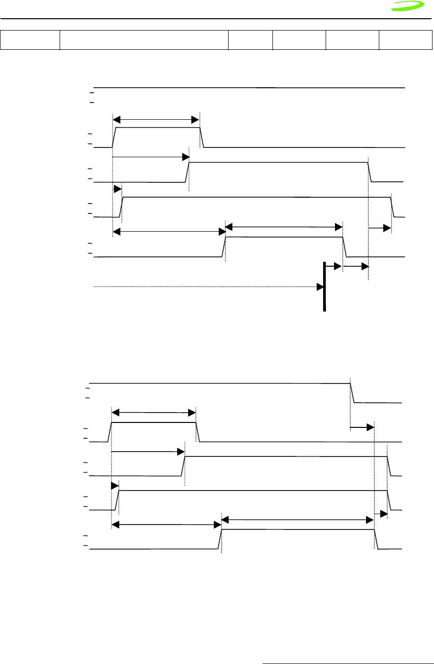
Specifications Expedite G301 OEM Module Specifications 35
P/N 90023363 Revision 1.9
Will be reduced to <200ms.
Figure 4 Pulsed Power-on, ATH4 Command Shutdown
Figure 5 ATH4 Command Not Issued (Method not Preferred)
TRESET Reset Pulse timing TBD mS
P
W
R
O
N
PUL_PWRENb
PWR_LATCH
(internal signal)
VCC_HOST
(internal power)
t
RDY PWR
MDM RDY
Modem not on or Software Initializing
Modem Initialized and Application Running
ATH4 Command
Issued
t
POWERUP
H
L
H
L
H
L
H
L
H
L
t
MODEMOFF
(De-registering
From Network)
PWRON
PUL PWREN
PWR_LATCH
(internal
VCC_HOST
(
in
te
rn
a
l
MDM RDY
Modem not on or Software Initializing
Modem Initialized and Application Running
* ATH4 Command Not Issued
(
Method Not Preferred
)
t
POWERUP
H
L
H
L
H
L
H
L
H
L
T
MODEMOF
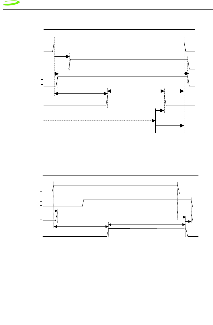
36 Specifications Expedite G301 OEM Module Specifications
Revision 1.9 P/N 90023363
Figure 6 Power Enable-On, ATH4 Command Shutdown
Figure 7 Power Enable On, Power Enable Shutdown
Baseband Connector on Expedite
The following sections detail the baseband connector. All baseband connectors meet UL 94V0
flammability requirements.The specifics of the connector are provided below.
PWRON
PUL_PWRENb
PWR_LATCH
(internal signal)
VCC_HOST
(internal
MDM_RDY
Modem not on or Software Initializing
Modem Initialized and Application
Ri
ATH4 Command
Issued
H
L
H
L
H
L
H
L
H
L
tMODEMOFF
(De-registering
From
PWRON
PUL_PWRENb
PWR_LATCH
(internal signal)
VCC_HOST
(internal power)
MDM_RDY
Modem not on or Software Initializing
Modem Initialized and Application Running
tMODEMOFF
H
L
H
L
H
L
H
L
H
L
* ATH4 Command Not Issued (Method Not Preferred)
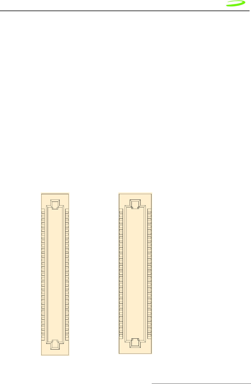
Specifications Expedite G301 OEM Module Specifications 37
P/N 90023363 Revision 1.9
Baseband Connector Part Numbers*
* For reference only – refer to approved parts list for current information. M Type,
“Plug”, appears visually as a female.
Baseband Mating Connector on the Host
The recommended mating connector is:
Baseband Connector Pin Numbering
Novatel Part Number 21823060
CSC Part Number CSC70P01RB-TR
SMK Part Number CPB7270-1211
Novatel Part Number 21823061
CSC Part Number CSC70S01RB-TR
SMK Part Number CPB7170-0111
Pin Numbering Convention - Plug Pin Numbering Convention - Socket
(MODULE CONNECTOR – TOP VIEW) (HOST CONNECTOR – TOP VIEW)
B1/2
B35/70A35/69
A1/1
A36/69B35/70
A1/1B1/2

38 Specifications Air Interface
Revision 1.9 P/N 90023363
Antenna Port
The antenna port is an MMCX type coaxial connector with 50 ohm impedance.
Antenna Connector
The antenna connector is an MMCX type coaxial connector with 50 ohm impedance.
Novatel Part Number: 21723118
Vendor Part Number: Huber and Suhner – 82MMCX-S50-0-2 6506
Mating Antenna Connector
The mating antenna connector is the appropriate MMCX plug. An example is an AEP
8905-1521-003 connector with a RG316 cable.
Mounting Features
Two mounting holes are provided on the Expedite G301. The mounting holes are
compatible with M2 metric screws.
Double-sided adhesive tape can also be used as an option to mount the module.
However, the mechanical design is left up to the integrator to ensure that the mechanical
mounting and restraint is adequate for the application.
Air Interface
Table 17: Air Interface Data Rates
Table 18: Radio Channel Frequency
Coding
Scheme
Data Rates per Time Slot
(Kbps)
Maximum Data Rate (8
Time Slots)
CS1 9.05 72.4
CS2 13.4 107.2
CS3 15.6 124.8
CS4 21.4 171.2
Radio Channel Frequency
Bands Channel Tx Rx
P-GSM 900 1 < n < 124 Freq(n)=890+0.2*n Freq(n)=935+0.2*n
E-GSM 900 0 < n < 124
975 < n < 1023
Freq(n)=890+0.2*n
Freq(n)=890+0.2*(n-1024)
Freq(n)=935+0.2*n
Freq(n)=935+0.2*(n-1024)
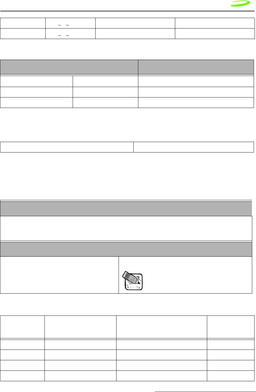
Specifications Subscriber Identification Module (SIM) 39
P/N 90023363 Revision 1.9
Table 19: Radio Power Index
Table 20: PCS Gain Index
Subscriber Identification Module (SIM)
Table 21: SIM Card Specifications
Table 22: SIM Card Contacts
DCS 1800 512 < n < 885 Freq(n)=1710.2+0.2*(n-512) Freq(n)=1805.2+0.2*(n-512)
PCS 1900 512 < n < 810 Freq(n)=1850.2+0.2*(n-512) Freq(n)=1930.2+0.2*(n-512)
Radio Power Index
Bands Index Power
GSM 900 5-19 2dB incremental steps
PCS 1900/DCS 1800 0-15 2dB incremental steps
0 - 25 0 = min gain, 25 = max gain
Physical Dimension and Weight
Size Width: 25mm (1.0”)
Length: 15 mm (0.60”)
Thickness: 0.76mm (0.30”)
Mechanical: Storage, Transportation and Operational
Temperature -25oC to 70oC
May exceed occasional peaks of up
to 85oC.
Contact
Number Signal Voltage Used
1 Supply Voltage 2.7 to 3.3 VDC Yes
2 Reset 0.0 to 3.0 VDC Yes
3 Clock 0.0 to 3.0 VDC Yes
4 No Connection NC No

40 Specifications Modes of Operation
Revision 1.9 P/N 90023363
Modes of Operation
The following modes of operation are listed and described below:
•Sleep
•SMS Messaging
•Circuit Switched
•GPRS Data
•Standby
Sleep
SLEEP mode provides the user with enhanced power savings by suspending unused
services while powering down other portions of the device. This power savings mode
occurs automatically and is transparent to the user. SLEEP mode can have a
considerable effect on the useful operating intervals between recharging. The modem
draws its power from the host thus affecting the host’s operational time.
SMS Messaging
SMS Messaging utilizes a very small portion of the data stream to send text-based
messages to units actively connected to the network. SMS Messages can be received in
either Standby, GPRS Data or Circuit switched modes. This feature provides a method of
sending text messages between network devices or other devices connected via the
Internet. SMS messages are limited to 160 bytes of data.
Circuit Switched
A circuit switched session is initiated through a dial command (user initiated) or an
answer command (remote initiated). In both cases the modem sets up and maintains a
continuous data connection between the modem and the remote. This connection is
maintained regardless of whether data is being sent or received. The session can be
terminated by the ATH command or through DTR control.
During a circuit switched session the modem will not enter sleep mode.
GPRS Data
The GPRS data connection provides the most cost effective and efficient way to send
data over a GSM Network. The modem can chain together multiple slots to increase its
throughput, the charges are applied only to the intervals when sending data thus the
5 Ground 0.0 Yes
6 Programming VPP NC or VCC Yes
7 Data I/O 0.0 to 3.0 VDC Yes
8 No Connection NC No

Specifications Application Information 41
P/N 90023363 Revision 1.9
dead time, typical in a circuit switched call, are eliminated. The GPRS session is
originated by dialing a dialup number, at which time an IP address is assigned to the
modem.
Standby
When not in sleep mode or either of the data modes (Circuit switched or GPRS), the
modem will actively scan for channels, listening for paging information and maintaining its
connection with the network. Standby mode is automatically entered when the unit is
powered up and will be activated whenever the modem leaves a data mode. Periodically,
the modem must scan for channels, maintain its link with the network, or handoff from one
channel to another.
Application Information
Application information about using the Expedite G301 modem to embed GPRS data
capability into OEM products, please visit
http://www.nvtl.com/oem/index.html
Application notes can be obtained on-line at:
http://www.nvtl.com/pcproducts/g100.html
For integration assistance, please contact the Custom Engineering Solutions Group at
http://www.nvtl.com/prodserv/oem_custom.html

42 Specifications Application Information
Revision 1.9 P/N 90023363

M
M
M
Me
e
e
er
r
r
rl
l
l
li
i
i
in
n
n
n
a
a
a
an
n
n
nd
d
d
d
E
E
E
Ex
x
x
xp
p
p
pe
e
e
ed
d
d
di
i
i
it
t
t
te
e
e
e
Chapter 3: AT
Commands
AT Commands allow communications software to control and direct the modem.
The term AT is derived from the word ATtention, meaning to get the modem’s
attention. AT Commands are issued by an intelligent device to a modem to
perform a specific function. For example, AT Commands can be used to initiate
a call, answer a call or to simply transmit data.
The ETSI specification created a complete set of commands to interface with the
terminal adapter or modem as well as specifying certain commands from ITU 25.
To make the AT Command interface easier to understand and provide faster
customer integration, a number of the standard AT Commands have been
implemented to substitute some of the more specialized ETSI commands. All
commands relevant to the control and operation of the modem have been
implemented.
This chapter will provide the following information:
•Merlin AT Commands listed by functions
•AT Command explanations, including a description, syntax, parameters,
response and an example. For more information please see “AT
Command Set by Name” on page 53.
•The prefix AT obtains synchronization, identifies the character
parameters, and indicates that a command may be in the following
characters.
•AT Commands are not case sensitive; use upper or lower case letters in
the command syntax.
The symbol <cr> represents an AT command’s terminating
character, used to send the AT command to the modem. By default,
this terminating character is set to the carriage return character
assigned to the “Enter” key on your keyboard.
Topics Included in this Chapter
AT Command Set by Function. . . . . . . . . . . . . . . . . . . . . . . . . . . . . . . . . . . 44
AT Command Set by Name . . . . . . . . . . . . . . . . . . . . . . . . . . . . . . . . . . . . . . . . . . . . . 53
CME ERROR Codes for GSM 07.07 Commands. . . . . . . . . . . . . . . . . . . . . . . . . . . . 142
CMS Error Codes for GSM 07.05 Commands . . . . . . . . . . . . . . . . . . . . . . . . . . . . . . 143

44 AT Commands
Revision 1.9 P/N 90023363
AT Command Set by Function
Table 4: Generic AT Commands below, lists by function, the generic AT Commands that
can be used with Merlin modems. The general format of the command line is:
<prefix><command><cr>.
This list does not include commands used for calibration.
Simply move the mouse over the command to link to a detailed explanation.
Table 4: Generic AT Commands
Generic
AT Command
Reference ETSI 07.07,PCCA STD-
101 Response
A/ Re-issues last AT command given AGAIN
+++ ESC from Data mode to command mode ESCAPE
ATA Answer incoming call ANSWER
ATD[<n>][mgsm>] Mobile Originated call to dial table number DIAL
ATD[<mem><loc>]
[<mgsm>]
Originate call to phone number in memory <MEM>DIAL FROM MEM-
ORY
ATD[<ploc>][<mgs
m>]
Originate call to phone number in current memory DIAL FROM LOCATION
ATD[<str>][<mgsm
>]
Originate call to phone number in memory which corre-
sponds to alphanumeric field
<STR>DIAL USING STRING
ATDL Redial last telephone number used DIAL LAST NUMBER
ATE Set command echo mode ECHO MODE
ATH Disconnect existing connection HANG-UP (DISCONNECT)
ATI Display product identification information DISPLAY IDENTITY
ATI0 Request IMEI (International Mobile Equipment Identifier)
number.
IMEI: 001018-00-565563-5-
00 IMEI OK
ATL Set monitor speaker loudness SET SPEAKER LOUDNESS
ATM Set monitor speaker mode SET SPEAKER MODE
ATO Switch from command mode to data mode OPEN DATA MODE

AT Commands 45
P/N 90023363 Revision 1.9
ATP Select pulse dialing SELECT PULSE MODE
ATQ Set Result code presentation mode SET RESULT FORMAT
ATS0 Set number of rings before automatically answering the
call
AUTO-ANSWER THRESH-
OLD
ATS2 Modem goes from off-line to on-line data state. ESCAPRE CHARACTER
SELECTION
ATS3 Set command line termination character COMMAND LINE TERMINA-
TOR
ATS4 Set response formatting character RESPONSE FORMATTING
CHARACTER
ATS5 Set command line editing character COMMAND LINE EDITING
CHARACTER
ATS6 Set pause before blind dialing PAUSE BEFORE DIALING
ATS7 Set number of seconds to wait for connection completion CONNECTION TIMEOUT
ATS8 Set number of seconds to wait when comma dial modifier
used
COMMA CONNECTION
TIMEOUT
ATS10 Set disconnect delay after indicating the absence of data
carrier
DATA IDLE TIMEOUT
ATS12 The Escape sequence guard time selection register, S-
Register 12, is not actively used and will report a “0” when
queried. Normally the guard time is used to discriminate
between valid and invalid occurrences of the escape
sequence.
ESCAPE SEQUENCE
GUARD SELECTION
ATT Select tone dialing SET TONE DIALING
ATV Set result code format mode SET RESULT CODE FOR-
MAT MODE
ATX Set connect result code format and call monitoring SET CONNECT CODE AND
CALL MONITORING
ATZ Set all current parameters to user defined profile SET CONFIGURATION TO
USER DEFINED PROFILE
AT&C Set DCD function mode SET DCD MODE
AT&D Set DTR function mode SET DTR MODE
AT&F Set all current parameters to manufacturer defaults RESTORE FACTORY
DEFAULTS
AT&V Display current configuration DISPLAY CONFIGURATION
AT&W Store current parameter to user defined profile SAVE CONFIGURATION
AT+DR V.42bis data compression reporting control DATA COMPRESSION
REPORTING CONTROL
AT+DS V.42bis data compression control DATA COMPRESSION
CONTROL
AT+GCAP Request complete TA capabilities list CAPABILITES LIST

46 AT Commands
Revision 1.9 P/N 90023363
AT+GMI Request manufacturer identification MANUFACTURER IDENTI-
FICATION
AT+GMM Request TA model identification MODEL IDENTIFICATION
AT+GMR Request TA revision identification REVISION IDENTIFICATION
AT+GOI Request global object identification GLOBAL IDENTIFICATION
AT+GSN Request TA serial number identification (IMEI) SERIAL NUMBER IDENTIFI-
CATION
AT+ICF Set TE-TA control character framing CONTROL CHARACTER
FRAMING
AT+IFC Set TE-TA local data flow control LOCAL DATA FLOW CON-
TROL
AT+IPR Set fixed local rate FIXED LOCAL RATE

AT Commands 47
P/N 90023363 Revision 1.9
Table 5: Call Control Features AT Commands below, lists by function, the AT Commands
specific to accessing and troubleshooting the call control features used on Merlin
modems.
This list does not include commands used for calibration.
Table 5: Call Control Features AT Commands
Call Control AT
Command Reference ETSI 07.07 Response
AT+CACM Accumulated call meter (ACM) reset of
query
ACCUMULATED CALL METER
AT+CAMM Accumulated call meter maximum (acm-
max) set or query
ACCUMULATED CALL METER
MAXIMUM
AT+CAOC Advice of charge ADVICE OF CHARGE
AT+CBST Select bearer service type BEARER SERVICE TYPE
AT+CCFC Call forwarding number and conditions
control
CALL FORWARDING
AT+CCUG Closed user group control CLOSED USER GROUP
AT+CCWA Call waiting control CALL WAITING
AT+CEER Extended error report EXTENDED ERROR REPORT
AT+CGMI Request manufacturer identification MANUFACTURER IDENTIFI-
CATION
AT+CGMM Request model identification MODEL IDENTIFICATION
AT+CGMR Request revision identification REVISION IDENTIFICATION
AT+CGSN Request product serial number identifica-
tion (identical with +gsn)
SERIAL NUMBER IDENTIFI-
CATION
AT+CGOI Global Identity Request Identifier of device type.
AT+CSCS Select TE character set TE CHARACTER SET
AT+CSSN Enables presentation of supplementary
service notification result codes
SUPPLEMENTARY SERVICE
NOTIFICATION
AT+CSTA Select type of address SELECT TYPE OF ADDRESS
AT+CHLD Call hold and multiparty CALL HOLD AND MULTI-
PARTY
AT+CIMI Request international mobile subscriber
identityI
INTERNATIONAL MOBILE
SUBSCRIBER IDENTITY

48 AT Commands
Revision 1.9 P/N 90023363
AT+CLCC List current calls of ME LIST CURRENT CALLS
AT+CLCK Facility lock FACILITY LOCK
AT+CLIP Calling line identification presentation CALLING LINE IDENTIFICA-
TION PRESENTATION
AT+CLIR Calling line identification restriction CALLING LINE IDENTIFICA-
TION RESTRICTION
AT+CMEE Report mobile equipment error MOBILE EQUIPMENT ERROR
AT+COLP Connected line identification presentation CONNECTED LINE IDENTIFI-
CATION PRESENTATION
AT+COPN Read operator name OPERATOR NAME
AT+COPS Operator selection OPERATOR SELECTION
AT+CPAS Mobile equipment activity status MOBIL EQUIPMENT ACTIVITY
STATUS
AT+CPBF Find phone book entries PHONEBOOK ENTRIES
AT+CPBR Read current phone book entries READ PHONEBOOK ENTRIES
AT+CPBS Select phone book memory storage PHONEBOOK MEMORY
STORAGE
AT+CPBW Write phone book entry WRITE PHONEBOOK ENTRY
AT+CPIN Enter PIN ENTER PIN
AT+CPWD Change password CHANGE PASSWORD
AT+CR Service reporting control SERVICE REPORTING
AT+CRC Set cellular result codes for incoming call
indication
CELLULAR RESULT CODES
AT+CREG Network registration NETWORK REGISTRATION
AT+CRLP Select radio link protocol parameter for
original non-transparent data call
RADIO LINK PROTOCOL
AT+CSQ Signal quality report SIGNAL QUALITY
AT+FCLASS Fax: Select, Read or Test Service Class FAX CLASS
AT+FMI Fax: Report Manufactured ID FAX MANUFACTURER ID
AT+FMM Fax: Report Model ID FAX MODEL ID
AT+FMR Fax: Report Revision ID FAX REVISION ID
AT+VTD Tone durationD TMF DURATION
AT+VTS DTMF and tone generation (<tone> in {0-
9, *, #, a, b, c, d})
DTMF SIGNAL
AT+CUSD Unstructured supplementary service data UNSTRUCTURED SUPPLE-
MENTARY SERVICE DATA

AT Commands 49
P/N 90023363 Revision 1.9
AT+CPOL Preferred operator list PREFERRED OPERATOR
LIST
AT+CNUM Subscriber number SUBSCRIBER NUMBER
AT+CMUT Mute control MUTE
AT+CLVL Loudspeaker volume SPEAKER VOLUME
AT+CFUN Set phone functionality PHONE FUNCTIONALITY
AT+CMUX
(not enabled)
Multiplexor control MULTIPLEXOR CONTROL
AT+CSIM Generic sim access GENERIC SIM ACCESS
AT+CBC
(not fully
supported)
Battery charge BATTERY CHARGE
AT+CCLK
(not supported)
Clock CLOCK
AT+CALM Alert sound mode ALERT SOUND MODE
AT+CRSL Ringer sound level RINGER SOUND LEVEL
AT+CPUC Price per unit currency table PRICE PER UNIT CURRENCY
AT+CCWE Call meter maximum event CALL METER MAXIMUM
EVENT

50 AT Commands
Revision 1.9 P/N 90023363
Table 6: SMS Specific At Commands below, lists by function, the AT Commands specific to
accessing and troubleshooting the SMS feature used on Merlin modems.
This list does not include commands used for calibration.
Table 6: SMS Specific At Commands
SMS
AT Command Reference ETSI 07.05 Response
AT+CMGD Delete sms message DELETE SMS MESSAGE
AT+CMGF Select sms message formatT SMS MESSAGE FORMA
AT+CMGL List sms messages from preferred store LIST SMS MESSAGES FROM
PREFERRED STORE
AT+CMGR Read SMS message READ SMS MESSAGE
AT+CMGW Write SMS message to memory WRITE SMS MESSAGE TO
MEMORY
AT+CMSS Send SMS message from storage SEND SMS MESSAGE FROM
STORAGE
AT+CNMI New SMS message indications NEW SMS MESSAGE INDICA-
TIONS
AT+CPMS Preferred SMS message storage PREFERRED SMS MES-
SAGE STORAGE
AT+CRES Restore SMS settings RESTORE SMS SETTINGS
AT+CSAS Save SMS settings SAVE SMS SETTINGS
AT+CSCA Sms service center address SMS SERVICE CENTER
ADDRESS
AT+CSCB Select cell broadcast SMS messages SELECT CELL BROADCAST
SMS MESSAGES
AT+CSDH Show SMS text mode parameters SHOW SMS TEXT MODE
PARAMETERS
AT+CSMP Set SMS text mode parameters SET SMS TEXT MODE
PARAMETERS
AT+CSMS Select message service SELECT MESSAGE SERVICE

AT Commands 51
P/N 90023363 Revision 1.9
Table 7: GPRS Specific AT Commands below, lists by function, the AT Commands specific
to accessing and troubleshooting the issues specific to GPRS communications.
This list does not include commands used for calibration.
Table 7: GPRS Specific AT Commands
GPRS
AT Command Reference ETSI 07.07 Response
AT+CGDCONT Define PDP context PDP CONTEXT DEFINITION
AT+CGQREQ Quality of service profile (requested) REQUEST QOS PROFILE
AT+CGQMIN Quality of service profile (minimum acceptable) QUALITY OF SERVICE PRO-
FILE
AT+CGACT Context activation PDP CONTEXT CONTROL
AT+CGATT GPRS attach or detach GPRS ATTACH OR DEAT-
TACH
AT+CGPADDR Show PDP address SHOW PDP ADDRESS
AT+CGCLASS GPRS mobile station class GPRS MOBILE STATION
CLASS
AT+CGEREP Control unsolicited GPRS event reporting UNSOLICITED EVENT
REPORTING CTRL
AT+CGREG Network registration status REGISTRATION STATUS
AT+CGSMS Select service for MO SMS messages SERVICE FOR MO SMS
MSG’S

52 AT Commands
Revision 1.9 P/N 90023363
Table 8: Novatel Wireless Specific AT Commands below, lists by function, the AT
Commands specific to accessing and troubleshooting the issues specific to TTP
communications.
This list does not include commands used for calibration.
Table 8: Novatel Wireless Specific AT Commands
Novatel
Wireless
AT Command
Reference ETSI 07.07 Response
AT+CLTS Get local timestamp LOCAL TIMESTAMP
AT+CEXTHS External headset control EXTERNAL HEADSET
AT+CEXTBUT External headset button unsolicited result code reporting EXTERNAL HEADSET BUT-
TON
AT+CSMINS Unsolicited sim removal/insertion result code reporting SIM REMOVAL/INSERTION
ALERT
AT+CLDTMF Local DTMF generationL OCAL DTMF GENERATION
AT+CDRIND Unsolicited indication of a call drop or GPRS context termi-
nation
CALL DROP INDICATION

AT Commands 53
P/N 90023363 Revision 1.9
AT Command Set by Name
Each of the following sections discusses an individual AT command and its five
subsections listed below:
Description: describes the command and defines any conditions required to use the
command
Syntax: lists the syntax the command requires
Parameters: lists any parameters and values available to the command
Response: lists and defines any responses the command may return
Example: (optional) provides examples of the command
A/
Description: REPEAT LAST COMMAND
This command repeats the last command sent to the modem.
Syntax: A/<cr>
Parameters: None
Response: Returns the command response from the previous command.
Example: AT12<cr>
Novatel Wireless, Inc.
OK
A/<cr>
Novatel Wireless, Inc.
OK
+++
Description: ESCAPE SEQUENCE
This command is used to change the modem from data mode to command
mode. This command is not a Hayes-compatible command as the guard
time interval is not required. It is a public domain method (TIES) and is
only enabled with define VG_TIES_ESC_SEQUENCE.
If the modem receives the characters +++AT followed by a carriage return
(<cr>) within a 0.5 second time span, the modem interrupts the data flow
on the AT command interface, switches to command mode and interprets
all characters received before the next command line termination
character as commands.
This command can only be issued in data mode.

54 AT Commands
Revision 1.9 P/N 90023363
This command is not a Hayes-compatible command. It is a public domain
method (TIES) and is only enabled with define
VG_TIES_ESC_SEQUENCE.
Syntax: +++<cr>
Parameters: None
Response: This command will return the string OK.
Example: +++AT <cr>
ATA
Description: ANSWER
This command sets the modem to answer the next call. The modem
sends an off-hook signal to the remote station. Any additional commands
on the same command line are ignored. The modem switches to data
mode and after call is released, returns to command mode.
This command can be stopped by receiving a character during execution,
except during some states of connection establishment such as
handshaking.
Syntax: ATA<cr>
Parameters: None
Response: If the connection is successful the modem will return the string:
CONNECT<text>
then switches to data mode. The <text> is only displayed if the command
ATX has been set to a value greater than 0.
When the modem releases the call and returns to command mode, it
returns the string:
OK
If no connection is made, the modem will return the string:
NO CARRIER
Example: ATA<cr>
ATD[<n>][mgsm>]
Description: DIAL NUMBER
This command will instruct the modem to originate a call to a dialable number.
The modem attempts to set up an outgoing call.
This command can be stopped by receiving a character during execution,
except during some states of connection establishment such as
handshaking.

AT Commands 55
P/N 90023363 Revision 1.9
Syntax: ATD[<n>][<mgsm>]<cr>
Parameters:
n is the string of dialing digits and the optional V.25ter modifiers. The
valid dialing digits are:
0-9, * , #, +, A, B, C
and the V.25ter modifiers which are ignored:
mgsm is a string of GSM modifiers, where:
I is overrides the current Calling Line Identification Restriction
(CLIR) setting for the call
G,g displays the Closed User Group (CUG) information, set with
the command +CCUG
;signifies the call is a voice call and instructs the modem to
return to the command mode.
Response: If there is no dial tone, the modem will return the string:
NO DIALTONE
where the command ATX has been set to 2 or 4.
If there is an error and it is related to the mobile equipment’s (ME)
functionality, the modem will return the string:
+CME ERROR: <error>
If the connection is busy, the modem will return the string:
BUSY
where the command ATX has been set to 3 or 4.
If the connection cannot be established, the modem will return the string:
NO CARRIER
If the connection is successful and is non-voice call, the modem switches
to data state and the modem will return the string:
CONNECT<text>
where <text> is only displayed if the command ATX has been set to a value
greater than 0.
If connection successful and is a voice call, the modem will return the
string:
OK
When the modem releases the call and returns to command mode, it
returns the string:
OK

56 AT Commands
Revision 1.9 P/N 90023363
Example:
ATD9,555-1212<cr> DIAL 9, PAUSE, DIAL 5551212
ATD555-1234;<cr> DIAL 5551234
ATD555-09871G<cr> DIAL 5550987, OVERRIDE CLIR, DISPLAY CUG
ATD[<mem><loc>][<mgsm>]
Description: DIAL NUMBER FROM SIM PHONE BOOK MEMORY
This command will instruct the modem to originate a call to a dialable
number using reference to a number stored in the SIM’s phone book
memories.
Syntax: ATD[<mem><loc>][<mgsm>]
Parameters:
mem is the phone book at the designated memory location. There is no
<mem> for emergency calls (EN). It is comprised of the following
phone book parameters:
FD SIM fix phone-phone book
LD SIM last-phone-phone book
DC Mobile Equipment (ME) dialed calls list
ON SIM (or ME) own numbers (MSISDNs) list
SM SIM phone book
loc is an integer referring to a memory location that is in a range of
locations available in the phone book referenced. This must be
used with the mem parameter.
mgsm is a string of GSM modifiers, where:
I is overrides the current Calling Line Identification Restriction
(CLIR) setting for the call
G,g displays the Closed User Group (CUG) information, set with
the command +CCUG
;signifies the call is a voice call and instructs the modem to
return to the command mode.
Response: If there is no dial tone, the modem will return the string:
NO DIALTONE
where the command ATX has been set to 2 or 4.
If there is an error and it is related to the mobile equipment’s (ME)
functionality, the modem will return the string:
+CME ERROR: <error>

AT Commands 57
P/N 90023363 Revision 1.9
If the connection is busy, the modem will return the string:
BUSY
where the command ATX has been set to 3 or 4.
If the connection cannot be established, the modem will return the string:
NO CARRIER
If the connection is successful and is non-voice call, the modem switches
to data state and the modem will return the string:
CONNECT<text>
where <text> is only displayed if the command ATX has been set to a value
greater than 0.
If connection successful and is a voice call, the modem will return the
string:
OK
When the modem releases the call and returns to command mode, it
returns the string:
OK
Example: ATDFD1<cr> DATA CALL TO FD PHONE BOOK ENTRY
ATDLD3<cr> DATA CALL TO LD PHONE BOOK ENTRY
ATDDC2I;<cr> VOICE CALL TO DC PHONE BOOK ENTRY 2 NO CLIR
ATD[<ploc>][<mgsm>]
Description: DIAL NUMBER FROM INTERNAL MEMORY
This command will instruct the modem to originate a call to a dialable
number
Syntax: ATD[<ploc>][<mgsm>]<cr>
Parameters:
ploc is an integer referring to a mobile equipment phone number
stored at the specified location in the modem’s internal
memory.
mgsm is a string of GSM modifiers, where:
I overrides the current Calling Line Identification
Restriction (CLIR) setting for the call
G,g displays the Closed User Group (CUG) information, set
with the command +CCUG
;signifies the call is a voice call and instructs the modem
to return to the command mode.

58 AT Commands
Revision 1.9 P/N 90023363
Response: If there is no dial tone, the modem will return the string:
NO DIALTONE
where the command ATX has been set to 2 or 4.
If there is an error and it is related to the mobile equipment’s (ME)
functionality, the modem will return the string:
+CME ERROR: <error>
If the connection is busy, the modem will return the string:
BUSY
where the command ATX has been set to 3 or 4.
If the connection cannot be established, the modem will return the string:
NO CARRIER
If the connection is successful and is non-voice call, the modem switches
to data state and the modem will return the string:
CONNECT<text>
where <text> is only displayed if the command ATX has been set to a value
greater than 0.
If connection successful and is a voice call, the modem will return the
string:
OK
When the modem releases the call and returns to command mode, it
returns the string:
OK
Example: ATD2<cr>

AT Commands 59
P/N 90023363 Revision 1.9
ATD[<str>][<mgsm>]
Description: DIAL NUMBR FROM NAME SEARCH
This command will instruct the modem to originate a call to a dialable
number.
Syntax: ATD[<str>][<mgsm>]<cr>
Parameters:
str is a string that is searched for in the alphanumeric fields of
the phone books, located in all available memory types (i.e.
SIM, Mobile Equipment Phone Book, etc.).
mgsm is a string of GSM modifiers, where:
I is overrides the current Calling Line Identification
Restriction (CLIR) setting for the call
G,g displays the Closed User Group (CUG) information, set
with the command +CCUG
;signifies the call is a voice call and instructs the modem
to return to the command mode.
Response: If there is no dial tone, the modem will return the string:
NO DIALTONE
where the command ATX has been set to 2 or 4.
If there is an error and it is related to the mobile equipment’s (ME)
functionality, the modem will return the string:
+CME ERROR: <error>
If the connection is busy, the modem will return the string:
BUSY
where the command ATX has been set to 3 or 4.
If the connection cannot be established, the modem will return the string:
NO CARRIER
If the connection is successful and is non-voice call, the modem switches
to data state and the modem will return the string:
CONNECT<text>
where <text> is only displayed if the command ATX has been set to a value
greater than 0.
If connection successful and is a voice call, the modem will return the
string:
OK

60 AT Commands
Revision 1.9 P/N 90023363
When the modem releases the call and returns to command mode, it
returns the string:
OK
Example: ATDBobR<cr>

AT Commands 61
P/N 90023363 Revision 1.9
ATDL
Description: DIAL LAST NUMBER
This command will instruct the modem to originate a call to the last
telephone number used by the modem. The modem attempts to set up an
outgoing call.
This command can be stopped by receiving a character during execution,
except during some states of connection establishment such as
handshaking.
Syntax: ATDL[;]
Parameters: ;which signifies the call is a voice call and instructs the modem to return to
the command mode.
Response: If there is no dial tone, the modem will return the string:
NO DIALTONE
where the command ATX has been set to 2 or 4.
If there is no last number to dial or the number is invalid, the modem will
return the string:
+CME ERROR: <error>
If the connection is busy, the modem will return the string:
BUSY
where the command ATX has been set to 3 or 4.
If the connection cannot be established, the modem will return the string:
NO CARRIER
If the connection is successful and is non-voice call, the modem switches
to data state and the modem will return the string:
CONNECT<text>
where <text> is only displayed if the command ATX has been set to a value
greater than 0.
If connection successful and is a voice call, the modem will return the
string:
OK
When the modem releases the call and returns to command mode, it
returns the string:
OK

62 AT Commands
Revision 1.9 P/N 90023363
Example: Input Response
ATDL Connect (Data Call)
ATDL;(No signal given as this is a voice call)
ATE
Description: ECHO MODE
This command sets the echo mode of the modem, that is, whether or not
the modem echoes characters received from terminal while the modem is
in command mode.
Syntax: ATE[<n>]
Parameters: n = 0 or 1
0 turns echo mode off
1 turns echo mode on
Response: This command will return the string OK.
Example: ATE1<cr> All further data entered is ecohed
OK
ATE0<cr> All further data entered is ecohed
OK
ATH
Description: HANG-UP (DISCONNECT)
This command instructs the modem to disconnect from the current
connection and terminate the call.
Syntax: ATH[0]
Parameters: 0 This parameter is the default, as well as the only parameter, and does not
necessarily have to be typed with the command.
Response: This command will return the string OK, after the Data Carrier Detect
(DCD) is turned off, if it was previously on.
Example: ATH<cr> OK

AT Commands 63
P/N 90023363 Revision 1.9
ATI
Description: MANUFACTURING IDENTITY
This command will instruct the modem to display the informational text,
contained in the modem’s firmware, such as the manufacturer’s name.
Syntax: ATI or ATI5
Parameters: None
Response: This command will return information on its manufacturer. For
example:
Novatel Wireless, Inc.
GPRS PC Card 56600
Software Version: PN160-0300
Date: May 23 2001, Time: 14:17:39
Example: ATI<cr>
Novatel Wireless, Inc.
GPRS PC Card 56600
Software Version: PN160-0300
Date: May 23 2001, Time: 14:17:39
OK
ATI0
Description: IMIE IDENTITY
Request IMEI (International Mobile Equipment Identifier) number.
Syntax: ATI0<cr>
Parameters: None
Response: IMEI: 001018-00-565563-5-00 IMEI OK
Example: ATI0
ATL
Description: SET SPEAKER LOUDNESS
This command will set the modem’s speaker circuit volume. When the
modem is installed in a computer, it will use the computer’s default
speaker.
This command is ignored when the modem is connected to a GSM network.

64 AT Commands
Revision 1.9 P/N 90023363
Syntax: ATL[<n>]
Parameters: 0, 1, 2, 3
where:
0 sets the speaker volume to very low
1 sets the speaker volume to low
2 sets the speaker volume to medium
3 sets the speaker volume to high
Response: This command will return the string OK.
Example: ATL3<cr>
ATM
Description: ENABLE MODEM SPEAKER
This command turns the modem’s speaker circuit on or off. When the
modem is installed in a computer, it will use the computer’s default
speaker.
This command is ignored when the modem is connected to a GSM
network.
Syntax: ATM[<n>]
Parameters: 0, 1, 2
where:
0 turns the speaker off
1 turns the speaker on until the modem informs the terminating
equipment that a carrier has been detected
2 turns the speaker on while the modem is off-hook
Response: OK
Example: ATM1<cr> OK
ATO
Description: OPEN DATA MODE
This command switches the modem from command mode to data mode.
This command is generally used to return the modem to data mode after
the user has issued the command +++AT and worked in the modem’s
command mode.
Syntax: ATO[0]

AT Commands 65
P/N 90023363 Revision 1.9
Parameters: 0 This parameter is the default, as well as the only parameter, and does
not necessarily have to be typed with the command.
Response: If connection is not successfully resumed, the modem will return the
string:
NO CARRIER
If connection is successfully resumed, the modem will return the string:
CONNECT<text>
where <text> is only displayed if the command ATX has been set to a value
greater than 0.
Example: ATO<cr> <Data Field to and from Modem>
ATP
Description: PULSE DIAL MODE
This command is used to instruct the modem to dial the next telephone
number using pulse dialing. This command is a legacy command and is
ignored when the modem is connected to a GSM network.
Syntax: ATP<cr>
Parameters: None
Response: This command will return the string OK.
Example: ATP<cr>
ATQ
Description: QUIET MODE
This command is used to specify whether or not the modem will sent
result codes to the terminating equipment. Text sent from the modem to
the terminating equipment using the ATI command will not be affected.
Syntax: ATQ[<n>]
Parameters: 0, 1
0 instructs the modem to send the result codes; this is the default.
1 instructs the modem to suppress the result codes and not transmit
them to the terminating equipment.
Response: If this command has been set to 0, the modem’s response will be OK.
If this command has been set to 1, there will be no response from the
modem.
Example: ATQ0<cr>

66 AT Commands
Revision 1.9 P/N 90023363
ATS0
Description: LISTEN MODE
This command sets the number of rings the modem will wait before it will
answer the incoming call. This command sets the modem’s S-register 0.
Syntax: ATS0[=<n>][?]
Parameters: =<n>, ?
<n> is a number between 1 and 255 that represents the number of rings
the modem will wait before answering the incoming call. This
command sets the S-register 0 to the number specified in <n>. If
this command is set to 0, the modem will never answer the incoming
call.
? will query the S-register and return the register’s current value
Response: If the user has typed the command ATS0?, the modem will return the
current value of the register and the string OK. For example:
5
OK
If the user has typed the command ATS0=<n>, the modem will only return
the string OK.
Example: ATS0=5<cr> answer after 5 rings
OK
ATS2
Description: ESCAPE CHARACTER SELECTION
The escape sequence consists of three repetitions of the escape code
character, defined by S-Register 2 (default value: decimal 43(+)). The
escape sequence causes the modem to go to the off-line command state
from the on-line data state. After this escape sequence, the modem can
accept user's AT Commands.
Syntax: ATS2=<n><cr>
Parameters: <n> is the decimal value of the ASCII character used as the “escape”
character
Response: OK
Example: ATS2=43<cr>
OK

AT Commands 67
P/N 90023363 Revision 1.9
ATS3
Description: COMMAND TERMINATION CHARACTER
This command sets the character that will be used as the command line
termination character. The terminating character may be changed using
this command. This command sets the modem’s S-register 3.
Syntax: ATS3[=<n>][?]
Parameters: =<n>, ?
=<n> is the ASCII code number that represents the character to be used
as the command line termination character. This command sets S-
register 3 to the number specified in <n>. The valid values for this
parameter range from 0 to 127 and the default for this S-register is
13, which is the carriage return character.
? will query the S-register and return the register’s current value.
Response: If the user has typed the command ATS3?, the modem will return the
current value of the register and the string OK. For example:
13
OK
If you the user has typed the command ATS3=<n>, the modem will only
return the string OK.
Example: ATS3=23<cr>
ATS3?<cr>
ATS4
Description: EOL CHARACTER SELECTION
This command sets the character that will be used as the modem’s
response string end-of-line character. This command sets the modem’s S-
register 4.
Syntax: ATS4[=<n>][?]
Parameters: =<n>, ?
where:
=<n> is the ASCII code number that represents the character to be used
as the modem’s response string end-of-line character. This
command sets S-register 4 to the number specified in <n>. The valid
values for this parameter range from 0 to 127 and the default for this
S-register is 10, which is the line feed character.
? will query the S-register and return the register’s current value.

68 AT Commands
Revision 1.9 P/N 90023363
Response: If the user has typed the command ATS4?, the modem will return the
current value of the register and the string OK. For example:
10
OK
If the user has typed the command ATS4=<n>, the modem will only return
the string OK.
Example: ATS4=32<cr>
ATS4?<cr>
ATS5
Description: BACKSPACE CHARACTER
This command sets the character that will be used by the command line
as the backspace character; when the command line receives this
character, it will erase the character immediately preceding the cursor.
This command sets the modem’s S-register 5.
Syntax: ATS5[=<n>][?]
Parameters: =<n>, ?
=<n> is the ASCII code number that represents the character to be used
as the backspace character. This command sets S-register 5 to the
number specified in <n>. The valid values for this parameter range
from 0 to 127 and the default for this S-register is 8, which is the
backspace character assigned to the Backspace key on your
keyboard.
? will query the S-register and return the register’s current value.
Response: If the user has typed the command ATS5?, the modem will return the
current value of the register and the string OK. For example:
8
OK
If the user has typed the command ATS5=<n>, the modem will only return
the string OK.
Example: ATS5=110<cr>
ATS5?<cr>

AT Commands 69
P/N 90023363 Revision 1.9
ATS6
Description: CONNECTION HOLD OFF TIMER
This command sets the number of seconds the modem will wait before it
will begin blind dialing (dialing without checking for a dial tone). This
command sets the modem’s S-register 6.
This command is ignored when the modem is connected to a GSM network.
Syntax: ATS6[=<n>][?]
Parameters: =<n>, ?
=<n> is a number between 0 and 255 that represents the number of
seconds the modem will wait before blind dialing an outbound call.
This command sets S-register 6 to the number specified in <n>. The
default value for this register is 2.
? will query the S-register and return the register’s current value.
Response: If the user has typed the command ATS6?, the modem will return the
current value of the register and the string OK. For example:
4
OK
If the user has typed the command ATS6=<n>, the modem will only return
the string OK.
Example: ATS6=4<cr>
ATS7
Description: CONNECTION TIMEOUT
This command sets the number of seconds the modem will wait for the
connection to complete during an inbound or outgoing call, before it stops
attempting to connect. This command sets the modem’s S-register 7.
Syntax: ATS7[=<n>][?]
Parameters: =<n>, ?
=<n> is a number between 0 and 255 that represents the number of
seconds the modem will wait before stopping the connection
attempt. This command sets S-register 7 to the number specified in
<n>. The default value for this register is 60.
? will query the S-register and return the register’s current value.

70 AT Commands
Revision 1.9 P/N 90023363
Response: If the user has typed the command ATS7?, the modem will return the
current value of the register and the string OK. For example:
4
OK
If the user has typed the command ATS7=<n>, the modem will only return
the string OK.
Example: ATS7=4<cr>
ATS8
Description: COMMA DIAL MODIFIER
This command sets the value of the comma dial modifier, in seconds.
The comma dial modifier is placed in-between the digits of the telephone
number you wish to call to provide a pause. This might be used when
dialing 9 to get an outside telephone line. This command sets the
modem’s S-register 8.
This command is ignored when the modem is connected to a GSM
network.
Syntax: ATS8[=<n>][?]
Parameters: =<n>, ?
=<n> is a number between 1 and 255 that represents the number of
seconds the modem will wait to dial the remaining digits in the
telephone number. This command sets S-register 8 to the number
specified in <n>. If this command is set to 0, the there will be no
pause when the comma (,) is encountered. The default is set to 2.
? will query the S-register and return the register’s current value.
Response: If the user has typed the command ATS8?, the modem will return the
current value of the register and the string OK. For example:
2
OK
If the user has typed the command ATS8=<n>, the modem will only return
the string OK.
Example: ATS8=2<cr>
ATS10
Description: DATA CARRIER TIMEOUT
This command sets the amount of time, in 1/10th secs, the modem will
wait before returning on-hook, if it can no longer detect the data carrier.
This command sets the modem’s S-register 10.

AT Commands 71
P/N 90023363 Revision 1.9
Syntax: ATS10[=<n>][?]
Parameters: =<n>, ?
=<n> is a number between 1 and 255 that represents the number in 1/10th
secs the modem will wait before going on-hook, if it no longer
detects a data carrier. This command sets S-register 10 to the
number specified in <n>. The default value for this register is 15.
? will query the S-register and return the register’s current value.
Response: If the user has typed the command ATS10?, the modem will return the
current value of the register and the string OK. For example:
25
OK
If the user has typed the command ATS10=<n>, the modem will only return
the string OK.
Example: ATS10=25<cr>
ATS12
Description: ESCAPE SEQUENCE GUARD SELECTION
The Escape sequence guard time selection register, S-Register 12, is not
actively used and will report a “0” when queried. Normally the guard time
is used to discriminate between valid and invalid occurrences of the
escape sequence. The duration between escape codes must also be
within the guard time. After the modem recognizes a valid escape
sequence, an "OK" result code is returned. If an escape sequence is
valid, the modem will exit data mode and enter command mode. The ATO
command is used to go back to on-line data state.
Syntax: ATS12=<n><cr>
Parameters: <n> Regardless of the value entered, 0 will always be used.
Response: OK
Example: ATS12=10<cr>
ATT
Description: TONE DIALING
This command is used to instruct the modem to dial the next telephone
number using tone dialing. This command is a legacy command and is
ignored when the modem is connected to a GSM network.
Syntax: ATT<cr>
Parameters: None

72 AT Commands
Revision 1.9 P/N 90023363
Response: This command will return the string OK.
Example: ATT<cr> OK
ATV
Description: VERBOSE
This command displays the modem’s result codes in terse or verbose
form.
In terse form, all result codes are represented by an error code number
and all text messages have only a carriage return (<cr>) character
appended to them.
In verbose form, all result codes are returned as words or sentences and
all text messages have a carriage return-line feed (<cr><lf>) character
pair before and after the text message.
Syntax: ATV[<n>]
Parameters: 0, 1
0 will set the response format to terse
1 will set the response format to verbose
Response: If the command has been set to 0, it will return the response:
0
If the command has been set to 1, it will return the response:
OK
Example: ATV=1<cr> OK
ATX
Description: ACCESS CONTROL
This command will specify whether or not the modem will attempt to
detect a dial tone and busy signal, and what type of result code is
returned.
Syntax: ATX[<n>]
Parameters: 0, 1, 2, 3, 4
where:
0 will set the modem to not detect the dial tone or the busy signal and
return the result code CONNECT.
1 will set the modem to not detect the dial tone or the busy signal and
return the result code CONNECT<additional session-specific text>.

AT Commands 73
P/N 90023363 Revision 1.9
2 will set the modem to detect the dial tone, but not the busy signal. It will
also return the result code CONNECT<additional session-specific
text>.
3 will set the modem not to detect the dial tone, but detect the busy
signal. It will also return the result code CONNECT<additional
session-specific text>.
4 will set the modem to detect both the dial tone and the busy signal and
return the result code CONNECT<additional session-specific text>.
Response: This command will return the string OK.
Example: ATX4<cr>
ATZ
Description: RESET PARAMETERS TO SAVED SETTINGS
This command uses the user-defined modem settings profile stored in the
non-volatile memory as the active profile. If the user-defined profile is
invalid, the modem will use the factory default settings. Any additional
commands on the same command line are ignored. This command uses
the profile created by the AT&W command.
Syntax: ATZ[0]
Parameters: 0 This parameter is the default, as well as the only parameter, and
does not necessarily have to be typed with the command.
Response: This command will return the string OK.

74 AT Commands
Revision 1.9 P/N 90023363
AT&C
Description: DATA CARRIER DETECT (DCD) MODE
This command sets the data carrier detect mode.
Syntax: AT&C[<n>]
Parameters: 0, 1
0 sets the data carrier detect so it is always on
1 sets the data carrier detect so it is only on in the presence of a data carrier
Response: This command will return the string OK.
Example: AT&C1<cr>
AT&D
Description: DATA TERMINAL READY (DTR) CONTROL
This command defines how the modem responds, while in data mode, to
the data terminal ready (DTR) circuit changing state from ON to OFF.
Syntax: AT&D[<n>]
Parameters: 0, 1, 2
0 instructs the modem to ignore the data terminal ready state
1 instructs the modem to change to command mode, while remaining
connected to the call
2 instructs the modem to disconnect from the call and then change to
command mode. While the data terminal ready state is set to off, the
modem’s auto-answer function is also off.
Response: This command will return the string OK.
Example: AT&D2<cr>
AT&F
Description: RESTORE FACTORY DEFAULT SETTINGS
This command will return all the modem settings to their factory default
setting.
Syntax: AT&F[0]
Parameters: 0 This parameter is the default, as well as the only parameter, and
does not necessarily have to be typed with the command.
Response: <cr>hello<cr><LF><LF>OK
Example: AT&F0<cr>

AT Commands 75
P/N 90023363 Revision 1.9
AT&V
Description: VIEW ACTIVE PROFILE
This command will display the active profile settings on the terminating
equipment.
Syntax: AT&V[0]
Parameters: 0 This parameter is the default, as well as the only parameter, and
does not necessarily have to be typed with the command.
Response: The response will be a listing of the current configuration followed by
the string OK. For example
ACTIVE PROFILE :
E1 L1 M1 Q0 V1 X4 &C1 &D2
S0:0 S2:43 S3:13 S4:10 S5:8 S6:2 S7:60 S8:2 S10:15 S12:
+CBST: 7,0,1
+CSMS: 0
+CRLP: 61,61,48,6,0,3
+CRC: 0
+CR: 0
+FCLASS: 0
+IFC: 2,2
+IMODE: 0
+ICF: 3,3
+DR: 0
+CMGF: 0
+CSDH: 0
+CNMI: 2,1,0,0,0
+ILRR: 0
+IPR: 115200
+DS: 3,0,512,20
+CMEE: 0
+CREG: 0
+CCUG: 0,0,0
+CLIP: 0
+COLP: 0
+CCWA: 0
+CAOC: 1
+CLIR: 0
+CSCA: "+44385016005",145
+CSMP: 17,167
OK
Example: AT&V<cr>

76 AT Commands
Revision 1.9 P/N 90023363
AT&W
Description: SAVE MODEM PROFILE (SETTINGS)
This command stores the active modem settings profile in the modem’s
non-volatile memory. This stored profile can later be retrieved using the
ATZ command.
Syntax: AT&W[0]
Parameters: None
Response: This command will return the string OK.
Example: AT&W0<cr>
AT+CACM
Description: ACCUMULATED CALL METER (RESET OR QUERY)
This command reads or resets the Advice of Charge related accumulated
call meter (ACM) value in SIM file EF(ACM). ACM contains the total
number of home units for both the current and preceding calls.
Syntax: AT+CACM=[<password>] (Reset)
Parameters: passwd SIM PIN2
Response: <acm> string type; three bytes of the current ACM value in
hexadecimal format (e.g. "00001E" indicates decimal value 30)
Example: Input Response
Query AT+CACM? 00037F
Reset AT+CACM=opensesame OK
Te s t AT+CACM=? OK
AT+CALM
Description: ALERT SOUND MODE
This command sets the sound actions to to alert the user. This can be
used to enable or disable the sound utilized to alert the user. Available in
Command mode only.
Syntax: AT+CALM=<mode>
Parameters: 0 Normal Mode
<mode> 0 normal mode
1 silent mode (all sounds from ME are prevented)
Response: OK

AT Commands 77
P/N 90023363 Revision 1.9
Example:
Query +CALM: <mode>+CME ERROR: <err>
Tes t +CALM: (list of supported <mode>s)+CME ERROR: <err>
AT+CAMM
Description: ACCUMULATED CALL METER MAXIMUM
This command sets the Advice of Charge related accumulated call meter
maximum value in SIM file EF(ACMmax). ACMmax contains the maximum
number of home units allowed to be consumed by the subscriber.
Syntax: AT+CAMM=[<ACMMAX>[,<PASSWD>]]
Parameters: ACMMAX string type; three bytes, 000001-FFFFFF, of the max. ACM
value in hexa-decimal format (e.g. "00001E" indicates
decimal value 30). A value of 000000 will disable
ACMmax feature.
PASSWD SIM PIN2
Example: Input Response
Query AT+CAMM? 00037F
Set AT+CAMM=000400 OK
Tes t AT+CAMM=? OK
AT+CAOC
Description: ADVICE OF CHANGE
This command, when active, sends an unsolicited result code when the
current call meter (CCM) value changes, this will not be reported more
than once every 10 secs.
Syntax: AT+CAOC=<mode>
Parameters: 0, 1
0query CCM value
1 deactivate the unsolicited reporting of CCM value
2 activate the unsolicited reporting of CCM value
Example: Input Response
Query AT+CAOC? Current mode OK
Set AT+CAOC=1 OK
Tes t AT+CAOC=? List of possible selectIons

78 AT Commands
Revision 1.9 P/N 90023363
AT+CBC
Description: BATTERY CHARGE STATUS INDICATION
This command is used to indicate battery charge status.
Syntax: AT+CBC
Parameters: None
Response:
<bcs> battery connection status
0 ME is powered by the battery
1 ME has a battery connected, but is not
powered by it
2 ME does not have a battery connected
3 Recognized power fault, calls inhibited
<bcl> battery connection level
0 battery is exhausted, or ME does not have a
battery connected
1..100 battery has 1 to 100 % of capacity remaining
Example: Test Response: +CBC: (list of supported <bcs>s),(list of supported
<bcl>s)

AT Commands 79
P/N 90023363 Revision 1.9
AT+CBST
Description: Bearer Service Type
This command selects the bearer service <name> with data rate <speed>,
and the connection element <ce> to be used when data calls are
originated.
Syntax: AT+CBST=[<speed>] [,<name>[,<ce>]]]
Parameters:
<speed> 0 autobalancing
1 300 bps (V.21)
2 1200 bps(V.22)
3 1200/75 bps (V.23)
4 2400 bps (V22bis)
5 2400 bps(V.26ter)
6 4800 bps(V.32)
7 9600 bps (V.32)
12 9600 bps (V.34)
14 14400 bps (V.34)
65 300 bps (V.110)
66 1200 bps (V.110 or X.31 flag stuffing)
68 2400 bps (V.110 or X.31 flag stuffing)
70 4800 bps (V.110 or X.31 flag stuffing)
71 9600 bps (V.110 or X.31 flag stuffing)
75 14400 bps (V.110 or X.31 flag stuffing)
<name> 0 asynchronous modem
2 PAD access (asynchronous)
<ce> 0 transparent
1 non-transparent
Example: Query Response
Query AT+CBST? Current mode OK
Set AT+CBST=7,2,0 OK
Tes t AT+CBST=? List of possible selectIon

80 AT Commands
Revision 1.9 P/N 90023363
AT+CCFC
Description: CALL FORWARD
This command controls the call forwarding supplementary service.
Registration, erasure, activation, deactivation, and status query are
supported. Only <reas> and <mode> should be entered with mode (0-
2,4).
Syntax: AT+CCFC = <reas>, <mode>[, <number> [, <type> [,<class> [,
<subaddr> [,<satype> [,<time>]]]]]]
Parameters:
<reas> 0 unconditional
1 mobile busy
2 no reply
3 not reachable
4 all call forwarding (0-3)
5 all conditional call forwarding (1-3)
<mode> 0 disable
1 enable
2 query status
3registration
4 erasure
<number> string type phone number of forwarding address in
format specified by <type> asynchronous modem
<type> type of address in integer format; default 145 when
dialing string includes international access code
character "+", otherwise 129
<subaddr> string type subaddress of format specified by
<satype>
<satype> type of subaddress in integer; default 128
<class> 1 voice
2data
4fax
7all classes
<time> time, rounded to a multiple of 5 secs

AT Commands 81
P/N 90023363 Revision 1.9
<status> 0 not active
1active
Response: If <mode><>2 and command successful
OK
If there is a network error:
+CCFC: 0, 0
If <mode>=2 and command successful (only in connection with <reas> 0 –
3)
For registered call forward numbers:
+CCFC: <status>, <class1>[, <number>, <type> [, <time>]]
[<cr><LF>+CCFC: ....]
OK
If no call forward numbers are registered (and therefore all classes are
inactive):
+CCFC: <status>, <class>
OK
where <status>=0 and <class>=7
If error is related to ME functionality:
+CME ERROR: <err>
Example: Input Output
Query AT+CCFC? Current mode OK
Set AT+CCFC=0,1,,,,,, OK
Tes t AT+CCFC=? List of possible selectIon
AT+CCLK
Description: CLOCK SETTING, TIME OF DAY, DATE
This command is used to set the local time for the device as well as
determining the current time. ME does not support time zone indication.
Syntax: AT+CCLK=<time>
Parameters:
<time> string type value; format is "yy/MM/dd,hh:mm:ss”; where
characters indicate year (two last digits), month, day, hour,
minutes and seconds.
e.i 22:10:00 GMT equals to "94/05/06,22:10:00"

82 AT Commands
Revision 1.9 P/N 90023363
Response:
Query +CCLK: <time>+CME ERROR: <err>
Te s t OK
AT+CCUG
Description: CLOSER USER GROUP
This command sets the Closed User Group supplementary service
parameters as a default adjustment for all following calls.
Syntax: AT+CCUG=[<n>] [,<index>[,<info>]]]
Parameters:
<speed> 0disable CUG
1 enable CUG
71 9600 bps (V.110 or X.31 flag stuffing)
<index> 0...9 CUG index
10 no index (preferred CUG taken from
subscriber data)
<info> 0 no information
1 suppress OA (Outgoing Access)
2 suppress preferential CUG
3 suppress OA and preferential CUG
Response: +CCUG: <n>,<index>,<info>
OK
If error is related to ME functionality:
+CME ERROR: <err>
Example: Input Output
Query AT+CCUG? Current mode OK
Set AT+CCUG=0,1,,,,,, OK
Te s t AT+CCUG=? List of possible selections
AT+CCWA
Description: CALL WAITING
This command controls the Call Waiting supplementary service.
Activation, deactivation and status query are supported.
Syntax: AT+CCWA=[<n>] [,<mode>[,<class>]]]
Parameters:

AT Commands 83
P/N 90023363 Revision 1.9
Parameters:
<n> 0 disable unsolicited result code
1 enable presentation of an unsolicited result
code
71 9600 bps (V.110 or X.31 flag stuffing)
<mode> when <mode> parameter not given, network is not
interrogated
0disable
1 enable
2 query status
<class> is a sum of integers each representing a class of
information
1 voice (telephony)
2 data (bearer service)
4 fax (teleservice)
7 default (equals to all classes)
<status> 0 not active
1 enable
Example: Input Output
Query AT+CCWA? Current selection OK
Set AT+CCWA=1,1,1,1 OK
Tes t AT+CCWA=? List of possible selections
Unsolicited Response: When the presentation Call Waiting at the MODEM is enabled (and
Call Waiting is enabled) and a terminating call set up has
attempted during an established call, an unsolicited result code is
returned:
+CCWA: <number>,<type>,<class>[,<alpha>]
<number> string type phone number of calling address in
format specified by <type>
<type> type of address octet in integer format; 145 when
dialing string includes international access code
character "+", otherwise 129
<alpha> optional string type alphanumeric representation of
<number> corresponding to the entry found in a
phone book

84 AT Commands
Revision 1.9 P/N 90023363
AT+CCWE
Description: CALL METER MAXIMUM EVENT
GSM 07.07 specifies 30 seconds. However, the default setting is 5
seconds. Shortly before the ACM (Accumulated Call Meter) maximum
value is reached, an unsolicited result code +CCWV will be sent, if
enabled by this command. The warning is issued when 5 seconds call
time remains. It is also issued when starting a call if less than 5 s call
time remains.
Syntax: AT+CCWE=<mode>
Parameters:
<mode> 0 Disable call meter warning event
1 Enable call meter warning event
Response: OK or +CME ERROR: <err>Unsolicited result codes
supported:+CCWV Shortly before the ACM (Accumulated Call Meter)
maximum value is reached, an unsolicited result code +CCWV will be
sent, if enabled by this command. The warning is issued when 5
seconds call time remains. It is also issued when starting a call if less
than 5 s call time remains.
Query AT+CCWE? Current selection OK
Test AT+CCWE? list of possible selections
AT+CDRIND
Description: CALL DROP – GPRS PDP CONTEXT TERMINATION INDICATION
This unsolicited result code is useful with Class B operation and the
software Multiplexer. The unsolicited result code will be sent after the
“NO CARRIER” result code.
Syntax: AT+CDRIND=<n>
Parameters:
<n> 0 Unsolicited result code disabled
1 Unsolicited result code enabled
Response: OK
Status Query Response AT+CDRIND: Current selection OK
Unsolicited result code: AT+CDRIND: list of possible selections
<n> 0 Unsolicited result code disabled
1 Unsolicited result code enabled
<channel> 0 CS voice
1 CS Data/Fax
2 GPRS (PPP)

AT Commands 85
P/N 90023363 Revision 1.9
Query AT+CDRIND? Current selection OK
Test AT+CDRIND=? List of possible selections
Set AT+CDRIND=0 OK
AT+CEER
Description: EXTENDED ERROR REPORTING
Returns an extended report of the reason for the last call release.
Syntax: AT+CEER
Parameters: None
Response: +CEER: <report> OK
Example: Input Output
Query AT+CEER Current extended error report OK
Tes t AT+ C E ER =? OK
AT+CEXTBUT
Description: EXTERNAL HEADSET BUTTON
This command sets the modem to either deliver an indication of a button
being pressed or not. This can be performed on a polling basis or under
interrupt control (unsolicited). The default setting is 0.
Syntax: AT+CEXTBUT=<n>
Parameters:
<n> 0 Disable unsolicited result code
1 Enable unsolicited result code
Response: OK
Status Query Response AT+CEXTBUT: <n>,<pressed>
Unsolicited result code :AT+CEXTBUT: <pressed>
<n> 0 Unsolicited result code disabled
1 Unsolicited result code enabled
<pressed> 0 Headset button not pressed
1 Headset button pressed
Query AT+CEXTBUT? Current selection OK
Test AT+CEXTBUT=? List of possible selections
Set AT+CEXTBUT=0 OK

86 AT Commands
Revision 1.9 P/N 90023363
AT+CEXTHS
Description: EXTERNAL HEADSET
This command sets the alert mechanism and also permits polling for the
current state of the headset jack, either present or absent.
Syntax: AT+CEXTHS=<n>
Parameters:
<n> 0 Disable unsolicited result code
1 Enable unsolicited result code
Response: OK
Status Query Response +CEXTHS: <n>,<attach>
<n> 0 Unsolicited result code disabled
1 Unsolicited result code enabled
<attach> 0 unattached external headset
1 attached external headset
Unsolicited result code: +CEXTHS: <attach>
Query AT+CEXTHS? Current selection OK
Test AT+CEXTHS=? List of possible selections
Set AT+CEXTHS=0 OK
AT+CFUN
Description: SET FUNCTIONALITY LEVEL
Sets the current functionality of the device. Typically used on phones and
voice applications. Support for this command will be hardware
dependant. For UPGRADE_SYSTEM_2, settings above 1 are not
supported.
Syntax: AT+CFUN=<fun>[,<rst>]
Parameters:
<fun> 0 minimum functionality
1 full functionality (Default)
2 disable phone transmit RF circuits only
3 disable phone receive RF circuits only
4 disable phone both transmit and receive RF circuits
5..127 reserved for manufacturers as intermediate states
between full and minimum functionality
<rst> 0 do not reset the ME before setting it to <fun> power
level

AT Commands 87
P/N 90023363 Revision 1.9
Response:
Query AT+CFUN? Current selection OK
Test AT+CFUN=? List of possible selections
Set AT+CFUN=1 OK
AT+CGACT
Description: PDP CONTEXT ACTIVATE / DEACTIVATE
This execution command is used to activate or deactivate the specified
PDP context(s).
Syntax: AT+CGACT=[<state>[,<cid>[,<cid>[,…]]]]
Parameters:
<cid> a numeric parameter which specifies a particular PDP
context definition (see +CGDCONT command). The
following parameters are defined in GSM 03.60 -
<state> indicates the state of PDP context activation
0 – deactivated
1 – activated
Other values are reserved and will result in an ERROR
response to the execution command.
Response: AT+CGACT?+CGACT: <cid>,<state>[<cr><LF>+CGACT:
<cid>,<state>[…]]
AT+CGAPNR
This command reads APNs from the store. The command can be provided
with an absolute APN index to read or an index range for a group of APNs
to fetch.
Description: Read records from the APN store.
Syntax: AT+CGAPNR:<index1>,[<index2>]
Parameters: <index1> index of APN record to read or start index of read list
<index2> stop index of record list
Response: User specifies index of record to read or range of records to display.
Returns the data contained within the specified APN record(s).
Entries that are invalid are not shown.
+CGAPNR:<index>,<apn>,<usage>,<description>,<user>,<password>,
OK
Example: AT+CGAPNR=<index1>,[<index2>]
Test: AT+CGAPNR=? Returns the parameter for the read operation.

88 AT Commands
Revision 1.9 P/N 90023363
AT+CGAPNW
This command writes or deletes an APN specified by a given index
number. The user provides the description of the APN to write. The
minimum description features an index in the case of a delete event or an
index and an APN in the case of a write event.
Description: Write/delete record from the APN store.
Syntax: AT+CGAPNW:<index>[<apn>,[<....>]]
Parameters: <index> index of APN records to read
<apn> APN string
<usage> usage for this APN (1=General IP, 2=WAP)
<description> description string
<user> user name string
<password> password string
Response: Writes supplied data to the specified APN record in the store. If only
the index field is supplied, the specified record is deleted.
OK
A CME error if the index is invalid or entered data is invalid:
+CME ERROR:invalid index
ERROR
+CME ERROR: invalid input value.
ERROR
Example: AT+CGAPNW:<index>[<apn>,[<usage>,[<description>[<user>,<password>
]]]]]

AT Commands 89
P/N 90023363 Revision 1.9
AT+CGATT
Description: GPRS ATTACHED OR DEATTACHED
This execution command is used to attach to, or detach the MT from, the
GPRS service.
Syntax: AT+CGATT= [<state>]
Parameters: <state> indicates the GPRS attach state
0 – attached
1 – detached
Other values are reserved and will result in an ERROR response to the
execution command.
Response: +CGATT:<state>
Query AT+CGATT? OK
Test AT+CGATT=?
Set AT+CGATT=0
AT+CGCLASS
Description: GPRS MOBILE STATION CLASS
Class A and B are not supported by this GPRS solution. Class C is only
supported for <class> values of “CG” and “CC”
Syntax: AT+CGCLASS= [<class>]
Parameters: <class> a string parameter which indicates the GPRS mobile class (in
descending order of functionality)
A class A (highest)
Bclass B
CG class C in GPRS only mode
CC class C in circuit switched only mode (lowest)
Response: +CGCLASS: <class>
AT+CGDCONT
Description: PDP CONTEXT DEFINED
This set command specifies PDP context parameter values for a PDP
context identified by the (local) context identification parameter <cid>.
Define the PDP context and APN address.
Syntax: AT+CGDCONT=[<cid>[,<PDP_type>[,<APN>[,<PDP_addr>[,<d_comp>[,<h_co
mp>[,<pd1>[,…[,pdN]]]]]]]]]

90 AT Commands
Revision 1.9 P/N 90023363
Parameters:
<cid> (PDP Context Identifier) a numeric parameter which
specifies a particular PDP context definition. The parameter
is local to the TE-MT interface and is used in other PDP
context-related commands. The range of permitted values
(minimum value = 1) is returned by the test form of the
command.
<PDP_type> (Packet Data Protocol type) a string parameter which
specifies the type of packet data protocol X25 ITU-T/CCITT
X.25 layer 3 IP Internet Protocol (IETF STD 5) OSPIH
Internet Hosted Octet Stream Protocol PPP Point to Point
Protocol (IETF STD 51)
<APN> (Access Point Name) a string parameter which is a logical
name that is used to select the GGSN or the external
packet data network. If the value is null or omitted, then the
subscription value will be requested.
<PDP_addr> a string parameter that identifies the MT in the address
space applicable to the PDP. If the value is null or omitted,
then a value may be provided by the TE during the PDP
startup procedure or, failing that, a dynamic address will be
requested. The read form of the command will continue to
return the null string even if an address has been allocated
during the PDP startup procedure. The allocated address
may be read using the +CGPADDR command.
<d_comp> a numeric parameter that controls PDP data compression.
0 off (default if value is omitted)
1 on Other values are reserved
At present only one data compression algorithm (V.42bis) is provided in
SNDCP. If and when other algorithms become available, a command will be
provided to select one or more of these.
<h_comp> a numeric parameter that controls PDP header
compression.
0 off (default if value is omitted)
1 on (other values are reserved)
<pd1>,…<pdN> zero to N string parameters whose meanings are
specific to the <PDP_type>. For PDP type
OSP:IHOSS the following parameters are defined:
<pd1> = <host> the fully formed domain name extended
hostname of the Internet host
<pd2> = <port> the TCP or UDP port on the Internet host
<pd3> = <protocol> the protocol to be used over IP on the
Internet - "TCP" or "UDP

AT Commands 91
P/N 90023363 Revision 1.9
Example: AT+CGDCONT? +CGDCONT:
<cid>,<PDP_type>,<APN>,<PDP_addr>,<data_co
mp>,<head_comp>[,<pd1>[,…[,pdN]]]
[<cr><LF>+CGDCONT:
<cid>,<PDP_type>,<APN>,<PDP_addr>,<data_co
mp>,<head_comp>[,<pd1>[,…[,pdN]]]
AT+CGEREP
Description: UNSOLICITED EVENT REPORTING CONTROL
Syntax: AT+CGEREP=[<mode>[,<bfr>]]
Parameters:
<mode> 0 buffer unsolicited result codes in the MT; if MT result
code buffer is full, the oldest ones can be discarded.
No codes are forwarded to the TE.
1 discard unsolicited result codes when MT-TE link is
reserved (e.g. in online data mode); otherwise
forward them directly to the TE
2 buffer unsolicited result codes in the MT when
MT?TE link is reserved (e.g. in online data mode)
and flush them to the TE when MT-TE link becomes
available; otherwise forward them directly to the TE
<bfr> 0 MT buffer of unsolicited result codes defined within
this command is cleared when <mode> 1 or 2 is
entered
1 MT buffer of unsolicited result codes defined within
this command is flushed to the TE when <mode> 1
or 2 is entered (OK response shall be given before
flushing the codes)
Unsolicited Response:+CGEV: NW DEACT <PDP_type>,<PDP_addr>[,<cid>]
+CGEV: ME DEACT <PDP_type>,<PDP_addr>[,<cid>]
+CGEV: NW DETACH
+CGEV: ME DETACH
+CGEV: ME CLASS <class>
<PDP_type>Packet Data Protocol type (see +CGDCONT
command)
<PDP_addr>Packet Data Protocol address (see +CGDCONT
command}
<cid> Context Id (see +CGDCONT command).
Note: <cid> only given if known to the MT.
<class> GPRS mobile class (see +CGCLASS command)
Query AT+CGEREP? OK

92 AT Commands
Revision 1.9 P/N 90023363
Test AT+CGEREP=?
Set AT+CGEREP=0
AT+CGMI
Description: MANUFACTURERS IDENTITY REQUEST
Returns manufacturer identification text. Identical to the command
AT+GMI.
Syntax: AT+CGMI
Parameters: NONE
Response: Manufacturer’s ID
Example: Input Output
Query AT+CGMI Novatel Wireless, Inc. OK
Te s t AT+CGMI=? OK
AT+CGMM
Description: MODEL IDENTITY REQUEST
Returns product model identification text. Identical to the command
AT+GMM.
Syntax: AT+CGMM
Parameters: None
Response: <model identity>
Example: Input Output
Query AT+CGMM GPRS PC Card 1900 OK
Te s t AT+CGMM=? OK
AT+CGMR
Description: REVISION IDENTITY REQUEST
Returns product software version identification text. Identical to the
command AT+GMR.
Syntax: AT+CGMR
Parameters: None
Response: <software revision text>
Example: Input Output

AT Commands 93
P/N 90023363 Revision 1.9
Query A T + C G M R ? S o f t w a r e V e r s i o n : P N 1 6 0 - 0 3 0 0
Date: May 23 2001, Time: 14:17:39. OK
Tes t AT+CGMR=? OK
AT+CGOI
Description: GLOBAL IDENTITY REQUEST
Reports one or more lines of information text which permit the user to
identify the device, based on the ISO system for registering unique object
identifiers. Identical to the command AT+GOI.
Syntax: AT+CGOI
Parameters: None
Response: Identifier of device type.
AT+CGPADDR
Description: SHOW PDP ADDRESS
This command dictates the behavior of PPP in the ME but not the
behavior of any other GPRS-enabled foreground layer, e.g. browser.
Syntax: AT+CGPADDR=[<cid>[,<cid>[,…]]]
Parameters:
<cid> a numeric parameter which specifies a particular PDP
context definition (see +CGDCONT command). If no <cid> is
specified, the addresses for all defined contexts are
returned.
<PDP_addr> a string that identifies the MT in the address space
applicable to the PDP. The address may be static or
dynamic. For a static address, it will be the one set by the
+CGDCONT command when the context was defined. For a
dynamic address it will be the one assigned during the last
PDP context activation that used the context definition
referred to by <cid>. <PDP_address> is omitted if none is
available.
Response: +CGPADDR: <cid>,<PDP_addr>[<cr><LF>+CGPADDR:
<cid>,<PDP_addr>
AT+CGQMIN
Description: QUALITY OF SERVICE PROFILE (MINIMUM ACCEPTABLE)

94 AT Commands
Revision 1.9 P/N 90023363
Get current quality of service profile. This reports the minimum quality
standard that will be used by the device / network.
Syntax: AT+CGQMIN=[<cid>[,<precedence>[,<delay>[,<reliability>[,<peak>[,<mean>
]]
<cid> a numeric parameter which specifies a particular
PDP context definition (see +CGDCONT command).
The following parameters are defined in GSM 03.60
<precedence> a numeric parameter which specifies the
precedence class
<delay> a numeric parameter which specifies the delay class
<reliability> a numeric parameter which specifies the reliability
class
<peak> a numeric parameter which specifies the peak
throughput class
<mean> a numeric parameter which specifies the mean
throughput class
Response: AT+CGQMIN?+CGQMIN:
<cid>,<precedence>,<delay>,<reliability>,<peak>,<mean>[<cr><LF>
+CGQMIN: <cid>,<precedence>,<delay>,<reliability>,<peak>,<mean>[…]]
Query AT+CGQMIN? Current selection OK
Test AT+CGQMIN=? List of possible selections
Set AT+CGQMIN=<n> OK
AT+CGQREQ
Description: REQUEST QUALITY OF SERVICE PROFILE
Request quality of service from carrier.
Syntax: AT+CGQREQ=[<cid>[,<precedence>[,<delay>[,<reliability.>[,<peak>[,<mean
>]]]]]]
Parameters:
<cid> a numeric parameter which specifies a particular
PDP context definition (see +CGDCONT command).
The following parameters are defined in GSM 03.60
-
<precedence> a numeric parameter which specifies the
precedence class
<delay> a numeric parameter which specifies the delay class
<reliability> a numeric parameter which specifies the reliability
class
<peak> a numeric parameter which specifies the peak
throughput class

AT Commands 95
P/N 90023363 Revision 1.9
<mean> a numeric parameter which specifies the mean
throughput class
Response: +CGQREQ:<cid>,<precedence>,<delay>,<reliability>,<peak>,<mean>[<cr
><LF>+CGQREQ:
<cid>,<precedence>,<delay>,<reliability>,<peak>,<mean>[…]]
AT+CGREG
Description: GPRS NETWORK REGISTRATION STATUS
This set command returns the status of an unsolicited result code.
Syntax: AT+CGREG=[<n>]
Parameters:
<n> 0 disable network registration unsolicited result code
1 enable network registration unsolicited result code
+CGREG: <stat>
2 enable network registration and location information
unsolicited result code +CGREG: <stat>[,<lac>,<ci>]
Response: (Read Response)
+CGREG: <n>,<stat>[,<lac>,<ci>]
+CME ERROR: <err>
<n> 0 disable network registration unsolicited result code
1 enable network registration unsolicited result code
+CGREG: <stat>
2 enable network registration and location information
unsolicited result code +CGREG: <stat>[,<lac>,<ci>]
<stat> 0 device is not registered, ME is not currently
searching a new operator to register to
1 device is registered
<lac> string type; two byte location area code in
hexadecimal format (e.g. "00C3" equals 195 in
decimal)
<ci> string type; two byte cell ID in hexadecimal format
Query AT+CGREG? Current selection OK
Test AT+CGREG=? List of possible selections
Set AT+CGREG=<n> OK
AT+CGSMS
Description: SERVICE SELECTION FOR MO SMS MESSAGES

96 AT Commands
Revision 1.9 P/N 90023363
This set command is used to specify the service or service preference
that the MT will use to send MO SMS messages.
Syntax: AT+CGSMS=[<service>]
Parameters:
<service> a numeric parameter which indicates the service or
service preference to be used. The circuit switched
service route is the default method.
0GPRS
1 circuit switched
2 GPRS preferred (use CSD if GPRS not
available)
2 CSD preferred (use GPRS if CSD not
available)
Response: (Read Response)
+CGSMS: [<service>]<cr> +CME ERROR: <err> <service> see
above.
<n> 0 disable network registration unsolicited result code
1 enable network registration unsolicited result code
+CGREG: <stat>
2 enable network registration and location information
unsolicited result code +CGREG:
<stat>[,<lac>,<ci>]
<stat> 0 device is not registered, ME is not currently
searching a new operator to register to
1 device is registered
<lac> string type; two byte location area code in
hexadecimal format (e.g. "00C3" equals 195 in
decimal)
<ci> string type; two byte cell ID in hexadecimal format
AT+CGSN
Description: SERIAL NUMBER REQUEST
Reports the device serial number. Identical to the command AT+GSN.
Syntax: AT+CGSN
Parameters: None
Example: Input Output
Query AT+CGSN 01234567890123. OK
Te s t AT+CGSN=? OK

AT Commands 97
P/N 90023363 Revision 1.9
AT+CHLD
Description: CALL HOLD
Controls the supplementary services Call Hold, MultiParty and Explicit
Call Transfer. Calls can be put on hold, recovered, released, added to
conversation, and transferred. This supplementary service is only
applicable to teleservice 11 (Speech: Telephony).
Syntax: AT+CHLD=[<n>]
n 0 Terminate all held calls or UDUB (User Determined User
Busy) for a waiting call
1 Terminate all active calls (if any) and accept the other call
(waiting call or held call)
1X Terminate the active call number X (X= 1-7)
2 Place all active calls on hold (if any) and accept the other
call (waiting call or held call) as the active call
2X Place all active calls except call X (X= 1-7) on hold
3 Add the held call to the active calls
Example: Input Output
Query AT+CHLD? 1 OK
SET AT+CHLD=1 OK
Tes t AT+CHLD=? List of supported <n>s OK
AT+CIMI
Description: INTERNATIONAL MOBILE SUBSCRIBER IDENTITY REQUEST
Returns international mobile subscriber identity for identifying the
individual SIM which is attached to the device.
Syntax: AT+CIMI
Parameters: None
Response: International Mobile Subscriber Identity
Example: Input Output
Query AT+CIMI? 1234567890123455566
OK
Tes t AT+CIMI=? OK
AT+CLCC
Description: CURRENT CALL LIST
Returns a list of current calls.

98 AT Commands
Revision 1.9 P/N 90023363
Syntax: AT+CLCC
Parameters: None
[+CLCC:<id1>,<dir>,<stat>,<mode>,<mpty>[,<number>,
<type>[,<alpha>]]
<idx> integer type; call identification number as described
in GSM 02.30[19] sub clause 4.5.5.1; this number
can be used in +CHLD command operations.
<dir> 0 mobile originated (MO) call
1 mobile terminated (MO) call
<stat> state of call:
0active
1held
2 dialing (MO call)
3 alerting (MO call)
4 incoming (MT call)
5 waiting (MT call)
<mode> bearer/tele service:
0voice
1data
2fax
9 unknown
<mpty> 0 call is not one of multiparty (conference) call parties
1 call is one of multiparty (conference) call parties
<number> string type phone number in format specified by
<type>
<type> type of address octet in integer format; 145 when
dialing string includes international access code
character "+", otherwise 129
<alpha> string type alphanumeric representation of
<number> corresponding to the entry found in
phone book
Example: Input Output
Query AT+CLCC LIST FORMATTED AS ABOVE
OK
Te s t AT+CLCC=? OK

AT Commands 99
P/N 90023363 Revision 1.9
AT+CLCK
Description: FACILITY LOCK
This command is used to lock, unlock or interrogate an ME or a network
facility. A password is normally needed to perform such actions. When
querying the status of a network service (<mode>=2) the response line for
‘not active’ case (<status>=0) should be returned only if service is not
active for any <class>.
Syntax: AT+CLCK = <fac>, <mode>[,<passwd>[,<class>]]
Parameters:
<fac> “PS” PH-SIM (lock PHone to SIM card) (ME asks
password when other than current SIM card
inserted; ME may remember certain amount of
previously used cards thus not requiring password
when they are inserted).
“SC” SIM (lock SIM card) (SIM asks password in ME
power-up and when this lock command issued).
“AO” BAOC (Barr All Outgoing Calls) (refer GSM02.88[6]
clause 1)
“O” BOIC (Barr Outgoing International Calls) (refer
GSM02.88[6] clause 1)
“OX” BOIC-exHC (Barr Outgoing International Calls
except to Home Country) (refer GSM02.88[6] clause
1)
“AI” BAIC (Barr All Incoming Calls) (refer GSM02.88[6]
clause 2)
“IR” BIC-Roam (Barr Incoming Calls when Roaming
outside the home country) (refer GSM02.88 [6]
clause 2)
“AB” All Barring services (refer GSM02.30[19])
(applicable only for <mode>=0)
“AG” All out Going barring services (refer GSM02.30[19])
(applicable only for <mode>=0)
“AC” All in Coming barring services (refer GSM02.30[19])
(applicable only for <mode>=0)
“PN” Network Personalization (refer GSM 02.22[33])
"PU” network sUbset Personalization (refer GSM
02.22[33])
"PP” service Provider Personalization (refer GSM
02.22[33])
"PC” Corporate Personalization (refer GSM 02.22[33])
<mode> 0 unlock
1lock

100 AT Commands
Revision 1.9 P/N 90023363
2 query status
<passwd> password
<class> 1 voice
2data
4fax
7 all classes (default)
<status> 0 off
1on
Response: If <mode><>2 and command is successful
OK
If <mode>=2 and command is successful
+CLCK: <status>[,<class1>[<cr><LF>
+CLCK: <status>, class2....]] OK
If error is related to ME functionality:
+CME ERROR: <err>
Example: Input Output
Query AT+CLCK? 129
OK
Te s t AT+CLCK=? LIST OF SUPPORTED (<fac>s) OK
AT+CLDTMF
Description: GENERATE LOCAL DTMF TONE
Syntax: AT+CLDTMF=<n>,<dtmf-string>
Parameters:
<n> Duration of all DTMF tones in <dtmf-string> in 1/10
seconds.
<dtmf-string>As a max length of 20 characters of form <dtmf>, must be
entered between double quotes (“ “) and consists of
combinations of the following separated by commas.
<dtmf> A single ASCII characters in the set 0-9,#,*,A-D. This is
interpreted as a sequence of DTMF tones whose duration is
set by <n>.

AT Commands 101
P/N 90023363 Revision 1.9
Response: OK+CME ERROR
<err> AT+CLDTMF, without any parameters will abort any DTMF tone
currently being generated and any DTMF tone sequence
Query: AT+CLDTMF=? Current State OK
Set: AT+CLDTMF=<n> A list of possible selections
Tes t: AT+CLDTMF=
AT+CLIP
Description: CALLING LINE IDENTIFICATION PRESENTATION
TA enables or disables the presentation of the CLI at the TE. It has no
effect on the execution of the supplementary service CLIP in the network.
When the presentation of the CLI at the TE is enabled (and calling
subscriber allows), an unsolicited result code is returned after every RING
(or +CRING: <type>) at a mobile terminating call.
Syntax: AT+CLIP=<n>
Parameters:
<n> 0 suppress unsolicited result codes
1 display unsolicited result codes
Response: +CLIP: <number>, <type>
<number> string type phone number of calling address in format
specified by <type>
<type> type of address octet in integer format; 145 when dialing
string includes international access code character "+",
otherwise 129
Example: Input Output
Query AT+CLIP? List of supported N’s
Tes t AT+CLIP=? List of supported N’s
AT+CLIR
Description: CALLING LINE IDENTIFICATION RESTRICTION
TA restricts or enables the presentation of the CLI to the called party
when originating a call. The command overrides the CLIR subscription
(default is restricted or allowed) when temporary mode is provisioned as a
default adjustment for all following outgoing calls. This adjustment can be
revoked by using the opposite command.
Syntax: AT+CLIR=<n>
Parameters: <n> parameter sets the adjustment for outgoing calls

102 AT Commands
Revision 1.9 P/N 90023363
<n> 0 presentation indicator is used according to the subscription
of the CLIR service
1CLIR invocation
2 CLIR suppression
<m> parameter shows the subscriber CLIR service status in the network
<m> 0 CLIR not provisioned
1 CLIR provisioned in permanent mode
2 unknown (e.g. no network, etc.)
3 CLIR temporary mode presentation restricted
4 CLIR temporary mode presentation allowed
Response: +CLIR: <n>, <m> OK
Example: Input Output
Te s t AT+CLIR=? List of supported n’s
AT+CLTS
Description: GET LOCAL TIME STAMP
Query the master time source (local) for the current time.
Syntax: AT+CLTS
Parameters: None
Response:
<tds> time-string format: “yy/MM/dd,hh:mm:ss±zz” where
characters indicate year (last two digits), month, day, hours,
minutes, seconds and time zone.
AT+CLVL
Description: LOUDSPEAKER VOLUME SETTING
Sets the local loudspeaker volume level. If no loudspeaker provisions
exist, this command does nothing.
Syntax: AT+CLVL=<level>
Parameters:
<level> integer type value with manufacturer specific range
(smallest value represents the lowest sound level)
Response:
Query +CLVL: <level>+CME ERROR: <err>

AT Commands 103
P/N 90023363 Revision 1.9
Test +CLVL: (list of supported <level>s)+CME ERROR: <err>
AT+CMEE
Description: REPORT MOBILE EQUIPMENT ERROR
Modem disables or enables the use of result code +CME ERROR: <err>
as an indication of an error relating to the functionality of the mobile
equipment.
Syntax: AT+CMEE=<n>
Parameters:
<n> 0 disable result code
1 enable result code and use numeric values
2 enable result code and use verbose value
Response: <n> OK
Example: Input Output
Query AT+CMEE? <n>
OK
Tes t AT+CMEE=? List of supported <n>s
OK
AT+CMGD
Description: DELETE SMS MESSAGE
Deletes message from preferred message storage location.
Syntax: AT+CMGD=<index>
Parameters:
<index> integer type; value in the range of location numbers
supported by the associated memory
Response: OK
Example: Input Output
Tes t AT+CMGD=? OK
AT+CMGF
Description: SMS MESSAGE FORMAT
Sets parameter to dictate which input and output format of messages to
use.
Syntax: AT+CMGF = [<mode>]

104 AT Commands
Revision 1.9 P/N 90023363
Parameters:
<mode> 0 PDU mode
1 text mode
Response: OK
Example: Input Output
Query AT+CMGF? +CMGF: <mode> OK
Te s t AT+CMGF=? +CMGF: list of supported <mode>s OK
AT+CMGL
Description: LIST SMS MESSAGES
Returns messages with status value <stat> from message storage
<mem1> to the TE. If status of the message is 'received unread', status in
the storage changes to 'received read'.
Syntax: AT+CMGL [=<stat>]
Parameters:
<stat> Text Mode “REC UNREAD” Received unread message
(default)
“REC READ” Received read messages.
"STO UNSENT" Stored unsent messages
"STO SENT" Stored sent messages
"ALL" All messages
PDU Mode 0 Received unread messages (default)
1 Received read messages
2 Stored unsent messages
3 Stored sent messages
4 All messages
Response:
1. If text mode (+CMGF=1) and command successful: for SMS-SUBMITs
and/or SMS-DELIVERs:+CMGL: <index>,<stat>,<oa/
da>,[<alpha>],[<scts>][,<tooa/
toda>,<length>]<cr><LF><data>[<cr><LF>+CMGL:
<index>,<stat>,<da/oa>,[<alpha>],[<scts>][,<tooa/
toda>,<length>]<cr><LF><data>[...]] OK
2. If PDU mode (+CMGF=0) and command successful: +CMGL:
<index>,<stat>,[<alpha>],<length><cr><LF><pdu>[<cr><LF>+CM
GL: <index>,<stat>,[alpha],<length><cr><LF><pdu>[...]] OK
3. If error is related to ME functionality: +CMS ERROR: <err>

AT Commands 105
P/N 90023363 Revision 1.9
<alpha> string type alphanumeric representation of <da> or
<oa> corresponding to the entry found in MT phone
book; implementation of this feature is manufacturer
specific
<da> GSM 03.40 TP-Destination-Address, Address-Value
field in string format; BCD numbers (or GSM default
alphabet characters) are converted to characters;
type of address given by <toda>
<data> In the case of SMS: GSM 03.40 TP-User-Data in text
mode responses; format:
if <dcs> indicates that GSM 03.38 default alphabet is
used and <fo> indicates that GSM 03.40 TP-User-
Data-Header-Indication is not set: ME/TA converts
GSM alphabet into current TE character set
according to rules of Annex A
if <dcs> indicates that 8-bit or UCS2 data coding
scheme is used, or <fo> indicates that GSM 03.40
TP-User-Data-Header-Indication is set: ME/TA
converts each 8-bit octet into two IRA character long
hexadecimal number (e.g. octet with integer value
42 is presented to TE as two characters 2A (IRA 50
and 65))
In the case of CBS: GSM 03.41 CBM Content of
Message in text mode responses; format:
if <dcs> indicates that GSM 03.38 default alphabet is
used: ME/TA converts GSM alphabet into current TE
character set according to rules of Annex A.
if <dcs> indicates that 8-bit or UCS2 data coding
scheme is used: ME/TA converts each 8-bit octet
into two IRA character long hexadecimal number.
<length> integer type value indicating in the text mode
(+CMGF=1) the length of the message body <data>
(or <cdata>) in characters; or in PDU mode
(+CMGF=0), the length of the actual TP data unit in
octets (i.e. the RP layer SMSC address octets are
not counted in the length)
<index> integer type; value in the range of location numbers
supported by the associated memory
<oa> GSM 03.40 TP-Originating-Address, Address-Value
field in string format; BCD numbers (or GSM default
alphabet characters) are converted to characters;
type of address given by <tooa>
<pdu> In the case of SMS: GSM 04.11 SC address followed
by GSM 03.40 TPDU in hexadecimal format: ME/TA
converts each octet of TP data unit into two IRA
character long hexadecimal number (e.g. octet with

106 AT Commands
Revision 1.9 P/N 90023363
integer value 42 is presented to TE as two
characters 2A (IRA 50 and 65)). In the case of CBS:
GSM 03.41 TPDU in hexadecimal format.
<scts> GSM 03.40 TP-Service-Center-Time-Stamp in time-
string format (refer <dt>)
<toda> GSM 04.11 TP-Destination-Address Type-of-
Address octet in integer format (when first character
of <da> is + (IRA 43) default is 145, otherwise
default is 129)
<tooa> GSM 04.11 TP-Originating-Address Type-of-
Address octet in integer format (default
refer<toda>)
Example: Input Output
Te s t AT+CMGL=? +CMGF: list of supported <stats>s OK
AT+CMGR
Description: READ SMS MESSAGE
Returns SMS message with location value <index> from message
storage <mem1> to the TE. If status of the message is 'received unread',
status in the storage changes to 'received read'.
Syntax: AT+CMGR=<index>
Parameters:
<index> integer type; value in the range of location numbers
supported by the associated memory.
Response:
1.If text mode (+CMGF=1) and command successful: for SMS-DELIVER:
+CMGR: <stat>,<oa>,[<alpha>],<scts>
[,<tooa>,<fo>,<pid>,<dcs>,<sca>,<tosca>,<length>]<cr><LF><data>for
SMS-SUBMIT:+CMGR: <stat>,<da>,[<alpha>]
[,<toda>,<fo>,<pid>,<dcs>,[<vp>],<sca>,<tosca>,<length>]<cr><LF><data
>
2. If PDU mode (+CMGF=0) and command successful:
+CMGR: <stat>,[<alpha>],<length><cr><LF><pdu> OK

AT Commands 107
P/N 90023363 Revision 1.9
3. If error is related to ME functionality:
+CMS ERROR: <err>
<alpha> The string type alphanumeric representation of <da> or
<oa> corresponding to the entry found in MT phone book;
implementation of this feature is manufacturer specific.
<da> GSM 03.40 TP-Destination-Address, Address-Value field in
string format; BCD numbers (or GSM default alphabet
characters) are converted to characters; type of address
given by <toda>.
<data> In the case of SMS: GSM 03.40 TP-User-Data in text mode
responses; format:
if <dcs> indicates that GSM 03.38 default alphabet is used
and <fo> indicates that GSM 03.40 TP-User-Data-Header-
Indication is not set: ME/TA converts GSM alphabet into
current TE character set according to rules of Annex A.
If <dcs> indicates that 8-bit or UCS2 data coding scheme is
used, or <fo> indicates that GSM 03.40 TP-User-Data-
Header-Indication is set: ME/TA converts each 8-bit octet
into two IRA character long hexadecimal number (e.g. octet
with integer value 42 is presented to TE as two characters
2A (IRA 50 and 65))
In the case of CBS: GSM 03.41 CBM Content of Message in
text mode responses; format:
If <dcs> indicates that GSM 03.38 default alphabet is used:
ME/TA converts GSM alphabet into current TE character set
according to rules of Annex A.
If <dcs> indicates that 8-bit or UCS2 data coding scheme is
used: ME/TA converts each 8-bit octet into two IRA
character long hexadecimal number.
<dcs> Depending on the command or result code: GSM 03.38 SMS
Data Coding Scheme (default 0), or Cell Broadcast Data
Coding Scheme in integer format.
<fo> Depending on the command or result code: first octet of
GSM 03.40 SMS-DELIVER, SMS-SUBMIT (default 17),
SMS-STATUS-REPORT, or SMS-COMMAND (default 2) in
integer format.
<length> Integer type value indicating in the text mode (+CMGF=1)
the length of the message body <data> (or <cdata>) in
characters; or in PDU mode (+CMGF=0), the length of the
actual TP data unit in octets (i.e. the RP layer SMSC
address octets are not counted in the length).
<mid> GSM 03.41 CBM Message Identifier in integer format.

108 AT Commands
Revision 1.9 P/N 90023363
<oa> GSM 03.40 TP-Originating-Address, Address-Value field in
string format; BCD numbers (or GSM default alphabet
characters) are converted to characters; type of address
given by <tooa>.
<pdu> In the case of SMS: GSM 04.11 SC address followed by
GSM 03.40 TPDU in hexadecimal format: ME/TA converts
each octet of TP data unit into two IRA character long
hexadecimal number (e.g. octet with integer value 42 is
presented to TE as two characters 2A (IRA 50 and 65). In
the case of CBS: GSM 03.41 TPDU in hexadecimal format.
<sca> GSM 04.11 RP SC address Address Value field in string
format; BCD numbers (or GSM default alphabet characters)
are converted to characters; type of address given by
<tosca>.
<stat> 0 “REC UNREAD” Received unread messages
1 “REC READ” Received read messages
2 “STO UNSENT” Stored unsent messages
3 “STO SENT” Stored sent messages
4 “ALL” All messages
<toda> GSM 04.11 TP-Destination-Address Type-of-Address octet
in integer format (when first character of <da> is + (IRA 43)
default is 145, otherwise default is 129)
<tooa> GSM 04.11 TP-Originating-Address Type-of-Address octet
in integer format (default refer<toda>).
<tosca> GSM 04.11 RP SC address Type-of-Address octet in integer
format (default refer <toda>).
<vp> depending on SMS-SUBMIT <fo> setting: GSM 03.40 TP-
Validity-Period either in integer format (default 167) or in
time-string format (refer <dt>)
Example: Input Output
Te s t AT+CMGR=? +CMGR: list of supported <index>s OK
AT+CMGW
Description: WRITE SMS MESSAGE TO MEMORY
Transmits SMS message from terminal to memory storage. Memory
location of the stored message is returned. By default message status
will be set to 'stored unsent', but parameter allows other status values to
be given.
Syntax:
TEXT MODE: AT+CMGS=[<oa/da>[,<tooa/toda>]]<cr> MESSAGE TEXT
<ctrlZ>
PDU MODE: AT+CMGW==<length><cr> PDU IS GIVEN <ctrlZ>
SENDS MESSAGE <ctrlZ>

AT Commands 109
P/N 90023363 Revision 1.9
EXITS WITHOUT SENDING <esc>
Parameters:
<oa> GSM 03.40 TP-Originating-Address, Address-Value field in
string format; BCD numbers (or GSM default alphabet
characters) are converted to characters; type of address
given by <tooa>
<da> GSM 03.40 TP-Destination-Address, Address-Value field in
string format; BCD numbers (or GSM default alphabet
characters) are converted to characters; type of address
given by <toda>
<tooa> GSM 04.11 TP-Originating-Address Type-of-Address octet
in integer format (default refer <toda>).
<toda> GSM 04.11 TP-Destination-Address Type-of-Address octet
in integer format (when first character of <da> is + (IRA 43)
default is 145, otherwise default is 129)
<length> Integer type value indicating in the text mode (+CMGF=1)
the length of the message body <data> (or <cdata>) in
characters; or in PDU mode (+CMGF=0), the length of the
actual TP data unit in octets (i.e. the RP layer SMSC
address octets are not counted in the length)
<pdu> In the case of SMS: GSM 04.11 SC address followed by
GSM 03.40 TPDU in hexadecimal format: ME/TA converts
each octet of TP data unit into two IRA character long
hexadecimal number (e.g. octet with integer value 42 is
presented to TE as two characters 2A (IRA 50 and 65)). In
the case of CBS: GSM 03.41 TPDU in hexadecimal format.
<index> Index of message in selected storage <mem2>
Response: If writing is successful: +CMGW: <index> OK
If error is related to ME functionality: +CMS ERROR: <err>
Example: Input Output
Tes t AT+CMGW=? OK
AT+CMSS
Description: SEND STORED SMS MESSAGE
Sends message with location value <index> from message storage
<mem2> to the network (SMS-SUBMIT). If new recipient address <da> is
given, it shall be used instead of the one stored with the message.
Reference value <mr> is returned to the TE on successful message
delivery. Values can be used to identify message upon unsolicited
delivery status report result code.
Syntax: AT+CMSS=<index>[,<da>[,<toda>]]
Parameters:

110 AT Commands
Revision 1.9 P/N 90023363
<index> integer type; value in the range of location numbers
supported by the associated memory
<da> GSM 03.40 TP-Destination-Address, Address-Value field in
string format; BCD numbers (or GSM default alphabet
characters) are converted to characters; type of address
given by <toda>
<toda> GSM 04.11 TP-Destination-Address Type-of-Address octet
in integer format (when first character of <da> is + (IRA 43)
default is 145, otherwise default is 129)
<mr> GSM 03.40 TP-Message-Reference in integer format
Response: If text mode(+CMGF=1) and sending successful: +CMGS: <mr> OK
If PDU mode(+CMGF=0) and sending successful: +CMGS: <mr> OK
If error is related to ME functionality: +CMS ERROR: <err>
Example: Input Output
Te s t AT+CMSS=? OK
AT+CMUT
Description: This command is used to enable and disable the uplink voice muting
during a voice call.
Syntax: AT+CMUT=<n>
Parameters:
<n> 0 mute off
1 mute on
Response:
Query +CMUT: <n>+CME ERROR: <err>
Te s t +CMUT: (list of supported <n>s)
AT+CMUX
Description: This command is used to enable/disable the GSM 07.10 multiplexing
protocol control channel.
Syntax: AT+CMUX=<mode>
Parameters:
<mode> 0 Basic option (i.e. No multiplexer in operation)
1 Advanced option (GSM 07.10 multiplexer)
2 Proprietary option (manufacturer specific
multiplexer)
Response:

AT Commands 111
P/N 90023363 Revision 1.9
Query +CMUX: <mode>+CME ERROR: <err>
Test +CMUX: (list of supported <mode>s)
AT+CNMI
Description: SMS MESSAGE ARRIVAL INDICATION
Selects the procedure for receiving of new messages from the network.
Indicates to the TE when TE is active, e.g. DTR signal is ON. If TE is
inactive (e.g. DTR signal is OFF), message receiving should be done as
specified in GSM 03.38.
Syntax: AT+CNMI = [<mode>[,<mt>[,<bm>[,<ds>[,<bfr>]]]]]
Parameters:
<mode> 0 Buffer unsolicited result codes in the TA. If TA result
code buffer is full, indications can be buffered in
some other place or the oldest indications may be
discarded and replaced with the new received
indications.
1 Discard indication and reject new received message
unsolicited result codes when TA-TE link is reserved
(e.g. in on-line data mode). Otherwise forward them
directly to the TE.
2 Buffer unsolicited result codes in the TA when TA-TE
link is reserved (e.g. in on-line data mode) and flush
them to the TE after reservation. Otherwise forward
them directly to the TE.
3 Forward unsolicited result codes directly to the TE.
TA-TE link specific in band technique used to embed
result codes and data when TA is in on-line data
mode.
<mt> The rules for storing received SMs depend on its
data coding scheme (refer GSM 03.38 [2], preferred
memory storage (+CPMS) setting and this value:
0 No SMS-DELIVER indications are routed to the TE.
1 If SMS-DELIVER is stored into ME/TA, indication of
the memory location is routed to the TE using
unsolicited result code: +CMTI: <mem>,<index>
2 SMS-DELIVERs (except class 2) are routed directly
to the TE using unsolicited result code: +CMT:
[<alpha>],<length><cr><LF><pdu> (PDU mode
enabled) or +CMT: <oa>, [<alpha>],<scts>
[,<tooa>,<fo>,<pid>,<dcs>,<sca>,<tosca>,<length>]
<cr><LF><data> (text mode enabled; about

112 AT Commands
Revision 1.9 P/N 90023363
parameters in italics, refer command Show Text
Mode Parameters +CSDH). Class 2 messages
result in indication as defined in <mt>=1.
3 Class 3 SMS-DELIVERs are routed directly to TE
using unsolicited result codes defined in <mt>=2.
Messages of other classes result in indication as
defined in <mt>=1.
<bm> The rules for storing received CBMs depend on its
data coding scheme (refer GSM 03.38 [2]), the
setting of Select CBM Types (+CSCB) and the
following values:
0 No CBM indications are routed to the TE.
2 New CBMs are routed directly to the TE using
unsolicited result code: +CBM:
<length><cr><LF><pdu> (PDU mode enabled) or
+CBM:
<sn>,<mid>,<dcs>,<page>,<pages><cr><LF><data
> (text mode enabled).
<ds> 0 No SMS-STATUS-REPORTs are routed to the TE.
1 SMS-STATUS-REPORTs are routed to the TE using
unsolicited result code: +CDS:
<length><cr><LF><pdu> (PDU mode enabled) or
+CDS: <fo>,<mr>,[<ra>],[<tora>],<scts>,<dt>,<st>
(text mode enabled)
<bfr> 0 TA buffer of unsolicited result codes defined within
this command is flushed to the TE when <mode>
1...3 is entered (OK response shall be given before
flushing the codes).
1 TA buffer of unsolicited result codes defined within
this command is cleared when <mode> 1...3 is
entered.
Response: OK
Unsolicited Response:
+CMTI: <mem>,<index> Indication that new message has
been received
+CMT: ,<length><cr><LF><pdu> Short message is output directly
+CBM: <length><cr><LF><pdu> Cell broadcast message is output
directly
Example: Input Output
Te s t AT+CNMI=? OK
AT+CNUM
Description: SUBSCRIBER NUMBER

AT Commands 113
P/N 90023363 Revision 1.9
This is a query command is used to retrieve the current subscriber
number and associated information.
Syntax: AT+CNUM
<alphax> optional alphanumeric string associated with
<numberx> used character set should be the one selected with
commandSelect TE Character Set +CSCS
<numberx> string type phone number of format specified by <typex>
<typex> type of address octet in integer format (refer GSM 04.08 [8]
subclause 10.5.4.7)
<speed> as defined by the +CBST command
<service> service related to the phone number
0 asynchronous modem
1 synchronous modem
2 PAD Access (asynchronous)
3 Packet Access (synchronous)
4Voice
5Fax
<itc> information transfer capability
03.1 kHz
AT+COLP
Description: CONNECTED LINE IDENTIFICATION PRESENTATION
TA enables or disables the presentation of the COL(Connected Line) at
the TE for a mobile originated call. It has no effect on the execution of the
supplementary service COLR in the network. Intermediate result code is
returned from TA to TE before any +CR or V.25ter responses.
Syntax: AT+COLP=[<n>]

114 AT Commands
Revision 1.9 P/N 90023363
Parameters:
<n> 0 disable
1 enable
<m> 0 COLP not provisioned
1 COLP provisioned
2 Unknown (e.i no network)
Response: +COLP:,NUMBER>,<TYPE>[,SUBADDR>,SATYPE>[,<ALPHA>]]
<number> string type phone number of format specified by <type>
<type> type of address octet in integer format; 145 when dialing
string includes international access code character "+",
otherwise 1
<subaddr> string type sub address of format specified by <satype>
<satype> type of sub address octet in integer format (refer GSM
04.08 [8] sub clause 10.5.4.8)
<alpha> optional string type alphanumeric representation of
<number> corresponding to the entry found in phone book
Example: Input Response
Query AT+COLP? +COLP:<n>,<m> OK
Te s t AT+COLP=? +COLP:(List of supported <n>s) OK
AT+COPN
Description: READ OPERATOR NAME
Execute command returns the list of operator names from the ME. Each
operator code that has an alphanumeric equivalent in the ME memory
shall be returned.
Syntax: AT+COPN
Parameters: <numericn>: string type;operator in numeric format
<alphan>: string type;operator in long alphanumeric format
Response: +COPN: <numeric1>, <alpha>
[<CR><LF>+COPN: <numeric2>, <alpha2>[...]]

AT Commands 115
P/N 90023363 Revision 1.9
AT+COPS
Description: OPERATOR SELECTION
SET forces an attempt to select and register the GSM network operator. If
the selected operator is not available, no other operator shall be selected
(except <mode>=4). The selected operator name format shall apply to
further read commands (+COPS?).
QUERY returns a list of quadruplets, each representing an operator
present in the network. The formats may be unavailable, in this case the
field should be empty. The list of operators shall be in order: home
network, networks referenced in SIM, and other networks.
Syntax: AT+COPS = <mode>[, <format>[, <oper>]]
Parameters:
<oper> operator in format as per <mode>
<mode> 0 automatic mode; <oper> field is ignored
1 manual operator selection; <oper> field shall be
present
2 manual de-register from network
3 set only <format> (for read command +COPS?) – not
shown in Read command response
4 manual/automatic selected; if manual selection fails,
automatic mode (<mode>=0) is entered
<format> 0 long format alphanumeric <oper>;can be up to 16
characters long
1 short format alphanumeric <oper>
2 numeric <oper>; GSM Location Area Identification
number
Response: +COPS: (<stat>, <oper>, <oper>)s [,,(<mode>s),(<format>s)]
<stat> 0 unknown
1 operator available
2 operator current
3 operator forbidden
<oper> operator in format as per <mode>
<mode> 0 automatic mode; <oper> field is ignored
1 manual operator selection; <oper> field
2 manual de-register from network
3 set only <format> (for read command +COPS?) – not
shown in Read command response

116 AT Commands
Revision 1.9 P/N 90023363
4 manual/automatic selected; if manual selection fails,
automatic mode (<mode>=0) is entered
<format> 0 long format alphanumeric <oper>;can be up to 16
characters long
1 short format alphanumeric <oper>
2 numeric <oper>; GSM Location Area Identification
number
Example: Input Response
Query AT+COPS? List of supported <stat>,
<oper>,<mode>,<format> OK
Te s t AT+COPS=? +COPS: <mode>[,<format>[,<oper>]] OK
AT+CPAS
Description: MOBILE EQUIPMENT ACTIVITY STATUS
Returns the current equipment activity status.
Syntax: AT+CPAS
Parameters: None
Response: +CPAS: <pas> OK
0 ready
2 unknown (ME is not guaranteed to respond to instructions)
3 incoming call (ringing)
4 call in progress or call hold
Example: Input Response
Te s t AT+CPAS=? 4 OK
AT+CPBF
Description: PHONE BOOK, FIND ENTRIES
Returns phone book entries (from the current phone book memory
storage selected with +CPBS) containing alphanumeric string <findtext>.
Syntax: AT+CPBF=<findtext>
Parameters: Findtex - An ASCII string which may or may not be contained in the
phone book.
Response: [+CPBF: <index1>,<number>,<type>,<text>[[...]<cr><LF>
+CBPF: <index2>,<number>,<type>,<text>] OK]<index1>
<index1> integer type values in the range of location numbers of
phone book memory

AT Commands 117
P/N 90023363 Revision 1.9
<index2> integer type values in the range of location numbers of
phone book memory
<number> string type phone number of format <type>
<type> type of address octet in integer format ; 145 when dialling
string includes international access code character “+“,
otherwise 129
<findtext> string type field of maximum length <tlength>
<text> string type field of maximum length <tlength>
<nlength> integer type value indicating the maximum length of field
<number>
<tlength> integer type value indicating the maximum length of field
<text>
Example: Input Response
Query AT+CPBF=? OK
Tes t +CPBF: [<nlength)],[<tlength>] OK
AT+CPBR
Description: PHONE BOOK READ
Returns phone book entries in location number range <index1>...
<index2> from the current phone book memory storage selected with
+CPBS. If <index2> is left out, only location <index1> is returned.
Syntax: AT+CPBR = <index1>[, <index2>]
Parameters:
<index1> read as of this location number
<index2> read to this location number
<number> phone number
<type> type of number
<text> text for phone number
Response: +CPBR: <index1>, <number>, <type>, <text>[<cr><LF>+CPBR:
.....+CPBR: <index2>, <number>, <type>, <text>] OK
Example: Input Response
Tes t AT+CPBR=? +CPBR: (<index>s), <nlength>, <tlength>
OK

118 AT Commands
Revision 1.9 P/N 90023363
AT+CPBS
Description: PHONE BOOK STORAGE SELECTIONS
Selects current phone book memory storage, which is used by other
phone book commands.
Syntax: AT+CPBS=<storage>
Parameters:
<storage> DC Modem dialed calls list (+CPBW may not be
applicable for this storage)
FD SIM fix dialing-phone book
LD SIM last-dialing-phone book
ON SIM (or ME) own numbers (MSISDNs) list
SM SIM phone book
Example: Input Response
Query AT+CPBS? <storage> OK
Te s t AT+CPBS=? list of supported <storage>s OK
AT+CPBW
Description: PHONE BOOK WRITE ENTRY
This command writes phone book entry in location number <index> in the
current phone book memory storage selected with +CPBS. Entry fields
written are phone number <number> (in the format <type>) and text
<text> associated with the number. If those fields are omitted, phone
book entry is deleted. If <index> is limited, but <number> is given, entry
is written to the first free location in the phone book.
Syntax: AT+CPBW = [<index>], [<number>, [<type>, [<text>]]]
Parameters:
<nlength> max. length of phone number
<tlength> max. length of text for number
<index> location number
<number> phone number
<type> type of number; e.g. 145 when dialing string includes
international access code character "+", otherwise 129
<text> text for phone number
Response: +CPBW: (<index>s),<nlength>,( <typ>s),<tlength> OK

AT Commands 119
P/N 90023363 Revision 1.9
Example: Input Response
Tes t AT+CPBW+? (<index>s),<nlength>,( <typ>s),<tlength>
OK
The following characters in <text> must be entered via the escape
sequence:
GSM Char Seq. Seq.(hex) Note
\ \5C 5C 35 43 (backslash)
“ \22 5C 32 32 (string delimiter)
BSP \08 5C 30 38 (backspace)
NULL \00 5C 30 30 (GSM null)
‘0’ (GSM null) may cause problems for application layer software when
reading string lengths.
AT+CPIN
Description: ENTER PIN
Stores a password which is necessary before it can be operated (SIM
PIN, SIM PUK, PH?SIM PIN, etc.). If the PIN is to be entered twice, the
TA shall automatically repeat the PIN. If no PIN request is pending, no
action is taken and an error message, +CME ERROR, is returned to TE. If
the PIN required is SIM PUK or SIM PUK2, the second pin is required.
This second pin, <newpin>, is used to replace the old pin in the SIM.
Syntax: AT+CPIN=<pin>[, <new pin>]
Parameters:
<pin> string type; password
<new pin> string type; If the PIN required is SIM PUK or SIM PUK2:
new password
Response: +CPIN: <code> OK
READY no further entry needed
SIM PIN ME is waiting for SIM PIN
SIM PUK ME is waiting for SIM PUK
PH_SIM PIN ME is waiting for phone to SIM card (antitheft)
PH_SIM PUK ME is waiting for SIM PUK (antitheft)
SIM PIN2 PIN2, e.g. for editing the FDN book possible only if
preceding command was acknowledged with +CME
ERROR:17

120 AT Commands
Revision 1.9 P/N 90023363
SIM PUK2 possible only if preceding command was acknowledged
with error +CME ERROR:18.
Example: Input Response
Query AT+CPIN? <code> OK
Te s t AT+CPIN=? OK
AT+CPMS
Description: PREFERRED SMS MESSAGE STORAGE
Selects memory storages <mem1>, <mem2> and <mem3> to be used for
reading, writing.
Syntax: AT+CPMS = <mem1>[,<mem2>[,<mem3>]]
Parameters:
<mem1> Messages to be read and deleted from this memory storage
"SM" SIM message storage
<mem2> Messages will be written and sent to this memory storage
"SM" SIM message storage
<mem3> Received messages will be placed in this memory storage if
routing to PC is not set "+CNMI") "SM" SIM message
storage
<usedx> Number of messages currently in <memx>
<totalx> Number of messages storable in <memx>
Response: +CPMS: <used1>,<total1>,<used2>,<total2>,<used3>,<total3> OK
Example:
Input Response
Test: AT+CPMS=? list of supported <mem1>s OK
list of supported <mem2>s OK
list of supported <mem3>s OK
Query: AT+CPMS=?
CPMS:<mem1>,<used1>,<total1>,<mem2>,
<used2>,<total2>,<mem3>,<used3>,<total
3>OK
AT+CPOL
Description: PREFERRED OPERATOR LIST
This command is used to edit the SIM preferred list of networks. Execute
command writes an entry in the SIM list of preferred operators. If <index>
is given but <oper> is left out, entry is deleted. If <oper> is given but
<index> is left out, <oper> is put in the next free location. If only <format>
is given, the format of the <oper> in the read command is changed.

AT Commands 121
P/N 90023363 Revision 1.9
Syntax: AT+CPOL=[<index>][,<format>[,<oper>]]
Parameters:
<index> integer type: order number of operator in SIM preferred
operator list
<format> 0 long format alphanumeric <oper>
1 short format alphanumeric <oper>
2 numeric <oper><oper>string type:
<format> indicates whether alphanumeric or numeric format used
(see +COPS command)
Response:
Query AT+CPOL <index1>,<format>,<oper1>[<CR><LF>+CPOL:
<index2>,<format>,<oper2>[…]]+CME ERROR: <err>
Tes t AT+CPOL? (list of supported <index>s),(list of supported <format>s)
AT+CPUC
Description: PRICE PER UNIT AND CURRENCY TABLE SETTING
This command sets the conversion from minutes of use to the local
currency cost.
Syntax: AT+CPUC=<currency>,<ppu>[,<passwd>]
Parameters:
<currency> string type; three-character currency code (e.g. "GBP",
"DEM"); character set as specified by command Select TE
Character Set +CSCS
<currency> string type; price per unit; dot is used as a decimal
separator (e.g. "2.66")
<passwd> string type; SIM PIN2
Response: OK
Query AT+CPUC <currency>,<ppu>+CME ERROR: <err>
Tes t AT+CPUC? <err>
AT+CPWD
Description: PASSWORD CHANGE
Sets a new password for the facility lock function.
Syntax: AT+CPWD = <fac>, [<oldpwd>], <newpwd>
Parameters:
<fac> SC SIM (lock SIM card) (SIM asks password in ME
power-up and when this lock command issued)

122 AT Commands
Revision 1.9 P/N 90023363
AO BAOC (Barr All Outgoing Calls) (refer GSM02.88[6]
clause 1)
OI BOIC (Barr Outgoing International Calls) (refer
GSM02.88[6] clause 1)
OX BOIC-exHC (Barr Outgoing International Calls
except to Home Country) (refer GSM02.88[6] clause
1)
AI BAIC (Barr All Incoming Calls) (refer GSM02.88[6]
clause 2)
IR BIC-Roam (Barr Incoming Calls when Roaming
outside the home country) (refer GSM02.88 [6]
clause 2)
AB All Barring services (refer GSM02.30[19])
(applicable only for <mode>=0)
AG All outGoing barring services (refer GSM02.30[19])
(applicable only for <mode>=0)
AC All inComing barring services (refer GSM02.30[19])
(applicable only for <mode>=0)
P2 SIM PIN2<oldpwd> password specified for the
facility from the user interface or with command. If
an old password has not yet been set, <oldpwd> is
not to enter.
<newpwd> new password
<pwdlength> integer max. length of password
Response: +CPWD: (<fac>, <pwdlength>)s OK
Example: Input Response
Te s t AT+CPWD=? list of supported <fac>s,<pwdlength>s OK

AT Commands 123
P/N 90023363 Revision 1.9
AT+CR
Description: REPORTING CONTROL
Controls whether or not intermediate result code +CR: <serv> is returned
from the TA to the TE at a call set up. If enabled, an intermediate result
code is transmitted at the point during connect negotiation at which the TA
has determined which speed and quality of service will be used, before
any error control or data compression reports are transmitted, and before
any final result code (e.g. CONNECT) is transmitted.
Syntax: AT+CR=<mode>
Parameters:
0disable
1 enable
Response: +CR:<serv>
ASYNC asynchronous transparent
SYNC synchronous transparent
REL ASYNC asynchronous non-transparent
REL SYNC synchronous non-transparent
Example: Input Response
Query AT+CR? <mode> OK
Tes t AT+CR=? +CR:(0-1) OK
AT+CRC
Description: RESULT CODES, SET CELLULAR CODES FOR INCOMING CALL
INDICATION
Controls whether or not the extended format of incoming call indication is
used.
When enabled, an incoming call is indicated to the TE with unsolicited
result code +CRING: <type> instead of the normal RING.
ASYNC asynchronous transparent
SYNC synchronous transparent
REL ASYNC asynchronous non-transparent
REL SYNC synchronous non-transparent
FAX facsimile
VOICE voice
Syntax: AT+CRC=<mode>

124 AT Commands
Revision 1.9 P/N 90023363
Parameters:
<mode> 0 disable extended format
1 enable extended format
Response: OK
Example: Input Response
Query AT+CRC? 129 OK
Te s t AT+CRC=? 129,145 OK
AT+CREG
Description: REGISTRATION INDICATION
Returns the status of result code presentation and an integer <stat>
which shows whether the network has currently indicated the registration
of the ME. Location information elements <lac> and <ci> are returned
only when <n>=2 and ME is registered in the network.
Syntax: AT+CREG=[<n>]
Parameters:
<n> 0 disable network registration unsolicited result code
1 enable network registration unsolicited result code
+CREG: <stat>
<stat> 0 not registered, ME is not currently searching a new
operator to register to
1 registered, home network
2 not registered, but ME is currently searching a new
operator to register to
3 registration denied
4 unknown
5 registered, roaming
Response: +CREG: <n>,<stat> OK
Example: Input Response
Query AT+CREG? <n>,<stat> OK
Te s t AT+CREG=? list of supported <n>s OK
AT+CRES
Description: RESTORE MESSAGE SERVICE SETTINGS
This command restores SMS settings for +CMGF, +CNMI, +CSDH from
non-volatile memory to active memory.

AT Commands 125
P/N 90023363 Revision 1.9
Syntax: AT+CRES[=<profile>]<CR>
Parameters:
<profile> manufacturer specific profile number where settings are to
be stored
Response:
Tes t AT+CRESAS=?<CR> list of supported <profile>s OK
AT+CRLP
Description: RADIO LINK PROTOCOL SELECT
Sets radio link protocol (RLP) parameters used when non-transparent
data calls are setup, returns values supported. RLP versions 0 and 1
share the same parameter set. TA returns only one line for this set (where
<verx> is not present).
Syntax: AT+CRLP=[<iws>[,<mws>[,<T1>[,<N2>[,<ver>[,<T4>]]]]]]
Parameters:
<iws> 0 6I 255 Interworking window size (IWF to MS)
<mws> 0 6I 255 Mobile window cesiums to IWF)
<T1> 0 48 255 acknowledgment timer T1 in 10 ms units)
<N2> 0 6 255 retransmission attempts N2
<verx> 0-1 RLP version number in integer format; when
version indication is not present it shall equal
0. Versions 0 and 1 share the same
parameter set.
<T4> 0-3-255 Re-sequencing period in integer format, in
units of 10 ms. This is NOT used for RLP
versions 0 and 1.
Response: +CRLP: <iws>,<mws>,<T1>,<N2>,<ver1>,<T4>
Example: Input Response
Query AT+CRLP? returns current settings for RLP version.
RLP versions 0 and 1 share the same
parameter set. TA returns only one line for
this set (where <verx> is not present)
Tes t AT+CRLP=? list of possible settings. OK
AT+CRSL
Description: RINGER SOUND LEVEL
This command sets the ring volume for a phone or voice device.

126 AT Commands
Revision 1.9 P/N 90023363
Syntax: AT+CRSL=<level>
Parameters:
<level> integer type value with manufacturer specific range
(smallest value represents the lowest sound level)
Response:
Query +CRSL: <level>+CME ERROR: <err>
Te s t +CRSL: (list of supported <level>s)+CME ERROR: <err>
AT+CSAS
Description: RESTORE MESSAGE SERVICE SETTINGS
Restores SMS settings for +CMGF, +CNMI, +CSDH from non-volatile
memory to active memory.
Syntax: AT+CSAS[=<profile>]
Parameters: <profile>manufacturer specific profile number where settings are to
be stored
Response: OK
Example: Input Response
Te s t AT+CSAS=? list of supported <profile>s OK
AT+CSCA
Description: SMS SERVICE CENTER ADDRESS
Updates the SMSC address, through which mobile originated SMs are
transmitted. In text mode, setting is used by send and write commands.
In PDU mode, setting is used by the same commands, but only when the
length of the SMSC address coded into <pdu> parameter equals zero.
This command writes the parameters in the NON-VOLATILE memory.
Syntax: AT+CSCA = <sca>[,<tosca>]
Parameters:
<sca> GSM 04.11 RP SC address Address-Value field in string
format; BCD numbers (or GSM default alphabet characters)
are converted to characters; type of address given by
<tosca>

AT Commands 127
P/N 90023363 Revision 1.9
<tosca> Service center address format GSM 04.11 RP SC address
Type-of-Address octet in integer format default refer
<toda>)
Response: OK
Example: Input Response
Query AT+CSCA? +CSCA:<sca>,<tosca> OK
Tes t AT+CSCA=? OK
AT+CSCB
Description: CELL BROADCAST MESSAGE SELECTION
Selects which types of cell broadcast messages that are to be received by
the device.
The command writes the parameters in NON-VOLATILE memory.
Syntax: AT+CSCB=[<mode>[,mids>[,<dcss>]]]
Parameters:
<mode> 0 message types specified in <mids> and <dcss> are
accepted
1 message types specified in <mids> and <dcss> are
not accepted
<mids> string type; all different possible combinations of
CBM message identifiers (refer <mid>) (default is
empty string); e.g. "0,1,5,320-478,922".
<dcss> string type; all different possible combinations of
CBM data coding schemes (refer <dcs>) (default is
empty string); e.g. "0-3,5".
Response: +CSCB: <mode>,<mids>,<dcss> OK
Example: Input Response
Query AT+CSCB? +CSCB: <mode>,<mids>,<dcss> OK
Tes t AT+CSCB=? list of supported <mode>s OK
AT+CSCS
Description: SELECT CHARACTER SET

128 AT Commands
Revision 1.9 P/N 90023363
Sets which character set <chset> is used by the TE. The TA can then
convert character strings correctly between the TE and ME character
sets.
Syntax: AT+CSCS=[<chset>]
Parameters: CHSET GSM
Response: OK
Example: Input Response
Query AT+CSCS? GSM OK
Te s t AT+CSCS=? (GSM) OK
AT+CSDH
Description: SHOW SMS TEXT MODE PARAMETERS
Determines whether detailed header information is shown in text mode
result codes.
Syntax: AT+CSDH=<show>
Parameters:
<show> 0 do not show header values defined in commands
+CSCA and +CSMP (<sca>, <tosca>, <fo>, <vp>,
<pid> and <dcs>) nor <length>, <toda> or <tooa> in
+CMT, +CMGL, +CMGR result codes in text mode
1 show the values in result codes
Response: OK
Example: Input Response
Query AT+CSDH? +CSDH: <show> OK
Te s t AT+CSDH=? list of supported <show>s OK
AT+CSIM
Description: GENERIC SIM ACCESS
This command used to send a command to the SIM card/module and
return the appropriate response.
Syntax: AT+CSIM=<length>,<command>
Parameters:
<length> integer type: length of characters sent to the TE in
<command> or <response> (i.e. twice the number of octets
in the raw data)
<command> hex format: GSM 11.11 SIM command sent from the ME to
the SIM

AT Commands 129
P/N 90023363 Revision 1.9
Response: +CSIM: <command>,<response>
+CME ERROR: <err>
hex format: GSM 11.11 response from SIM to <command>
AT+CSMINS
Description: SIM REMOVAL/INSERTION ALERT
This command is used to set the method for reporting the transitions of
inserting and extracting the SIM from the carrier. It can also be used to
determine the current status of the SIM presence.
Syntax: AT+CSMINS=<n>
Parameters:
<n> 0 Disable unsolicited result code1Enable unsolicited result
code.
Response:
<n> 0 Disable unsolicited result code
1 Enable unsolicited result code
Query: AT+CSMINS?<n>, <inserted>Unsolicited result code:+CSMINS: <inserted>
Tes t: AT+CSMINS=? <inserted> 0 - SIM change inserted - removed
1 - SIM change removed - inserted
AT+CSMP
Description: SET SMS TEXT MODE PARAMETERS
This command selects values for additional parameters needed when SM
is sent to the network or placed in a storage when text mode is selected
(+CMGF=1). It is possible to set the validity period starting from when the
SM is received by the SMSC (<vp> is in range 0... 255) or define the
absolute time of the validity period termination (<vp> is a string).
This command writes the parameters to the NON-VOLATILE memory.
Syntax: AT+CSMP=[<fo>[<vp>[,pid>[,<dcs>]]]]
Parameters:
<fo> depending on the command or result code: first octet of
GSM 03.40 SMS-DELIVER, SMS-SUBMIT (default 17),
SMS-STATUS-REPORT, or SMS-COMMAND (default 2) in
integer format

130 AT Commands
Revision 1.9 P/N 90023363
<vp> depending on SMS-SUBMIT <fo> setting: GSM 03.40 TP-
Validity-Period either in integer format (default 167) or in
time-string format (refer <dt>)
Response: OK
Example: Input Response
Query AT+CSMP? +CSMP: <fo>,<vp> OK
Te s t AT+CSMP=? +CSMP: list of supported <fo>s and <vp>s
OK
AT+CSMS
Description: SELECT MESSAGE SERVICE
Select the type of SMS service.
Syntax: AT+CSMS= <service>
Parameters:
<service> 0 GSM 03.40 and 03.41 (the syntax of SMS AT
commands is compatible with GSM 07.05 Phase 2
version 4.7.0; Phase 2+ features which do not
require new command syntax may be supported
(e.g. correct routing of messages with new Phase
2+ data coding schemes))
128 SMS PDU mode - TPDU only used for sending/
receiving SMSs.
Response: +CSMS: <mt>,<mo>,<bm> OK
Mobile Terminated Messages:
<mt> 0 Type not supported
1 Type supported
Mobile Originated Messages
<mo> 0 Type not supported
1 Type supported
Broadcast Type Messages:
<bm> 0 Type not supported
1 Type supported
Example: Input Response
Query AT+CSMS? As above
Te s t AT+CSMS=? list of supported <services>s OK

AT Commands 131
P/N 90023363 Revision 1.9
AT+CSQ
Description: SIGNAL QUALITY REPORT
Execution command returns received signal strength indication and
channel bit error rate from the modem. Test command returns values
supported by the modem.
Syntax: AT+CSQ<cr>
Parameters: None
Response: +CSQ: <rssi>,<ber>
RSSI (in dBm) = (<rssi> X 2) –113 (FOR 0<= <rssi> <=31)
RSSI (in dBm) = -51 (FOR 31<= <rssi> <=98)
(FOR 99<= <rssi>) rssi is not known or not detectable
BER 0...7 as RXQUAL values in the table in GSM 05.08 [20] sub clause
8.2.4
BER 99 not known or not detectable
Example: Input Response
Tes t AT+CSQ=? list of RSSI and BLER OK
AT+CSSN
Description: SUPPLEMENTARY SERVICE NOTIFICATION
AT+CSTA
Description: SELECT TYPE OF ADDRESS
Selects the type of number for further dialing commands (ATD) according
to GSM specifications. The data services software only supports default
settings.
Syntax: AT+CSTA=[<type>]
Parameters:
Type 129 Type Unknown
145 Type International
Response: OK
Example: Input Response
Tes t AT+CSTA? 129 OK
Query AT+CSTA=? (129,145) OK

132 AT Commands
Revision 1.9 P/N 90023363
AT+CUSD
Description: UNSTRUCTURED SUPPLEMENTARY SERVICE DATA
This command sets the Unstructured response format as well as being
used to query the device with regards to the current session status.
Syntax: AT+CUSD=[<n>[,<str>[,<dcs>]]]
Parameters:
<n> 0 disable result code presentation in the TA
1 enable result code presentation in the TA
2 cancel session<str>string type: USSD string (see GSM
07.07 for use)
<dcs> integer type: GSM 03.38 Cell Broadcast Data Coding
Scheme
<m> 0 no further user action required
0 further user action required
1 USSD terminated by network
2 other local client has responded
3 operation not supportednetwork time out
Response:
Query: AT+CUSD? <n>+CME ERROR: <err>
Te s t : AT+CUSD=? (list of supported <n>s)
AT+DR
Description: DATA COMPRESSION REPORTING CONTROL
This command defines whether or not the result codes for the V.42bis
compression will be returned.
Syntax: AT+DR=[<n>][?]
Parameters: =[0, 1, ?], [?]
0 disables the compression result code reporting
1 enables the compression result code reporting
? queries the command and returns its current setting or displays the
valid values for the commands parameters
Response: AT+DR=[<n>], where value is 0 or 1, the command will return the
string OK.
AT+DR?, the command will return the strings:
+DR: <current command value, either 0 or 1>
OK

AT Commands 133
P/N 90023363 Revision 1.9
AT+DR=?, the command will return the strings:
+DR: (0-1)
OK
indicating the valid parameters for this command
If the result code reporting has been turned on, the following strings are
returned when the modem establishes a connection:
+DR: NONE data compression is not in use
+DR: V42B Rec. V42bis is in use in both direction
+DR: V42B RD Rec. V42bis is in use in receive direction only
+DR: V42B TD Rec. V42bis is in use in transmit direction only
AT+DS
Description: V.42bis COMPRESSION CONTROL
This command determines if the modem will use V.42bis data
compression and what the conditions of its use are after a call has been
set up. This command only works for data calls. During GSM connections,
data is transmitted transparently. The remote terminal adapter may or
may not support this compression. This command must be used in
conjunction with AT+CRLP command.
Syntax: AT+DS[=[<p0>,<n>,<p1>,<p2>]?]] [?]
Parameters:
<p0> defines the compression direction.
0No compression
1 transmit only
2 receive only
3 both directions, but allow for negotiation. This is the
default parameter.
<n> defines the V.42bis negotiation parameters.
0 allows negotiation of for compression to take place,
if allowed for in p0. This is the default parameter.
1 do not allow compression negotiation, even if
allowed for in p0. Instead, disconnect if there is a
difference.
<p1> defines the size of the dictionary. The valid value range is
512 to 2048. The default value is 512.
<p2> defines the maximum string size. The valid value range is 6
to 255. The default is 20.

134 AT Commands
Revision 1.9 P/N 90023363
? queries the command and returns its current setting or
displays the valid values for the commands parameters.
Response: AT+DS? is typed in, the modem will respond with a list of the
commands current settings. For example: +DS: 3,0,512,20 OK.
AT+DS=? is typed in, the modem will respond with a list of the valid value
rages for each of the command parameters. For example: +DS: (0-3),(0-
1),(512-1024),(6-64) OK.
AT+DS=<p0>,<n>,<p1>,<p2> is typed in, the modem will set each of the
parameters to the value defined in each parameter place holder and the
command will return the string OK.
Example: AT+DS=1,0,640,50<cr>
AT+DS=?<cr>
AT+DS?<cr>
AT+FCLASS
Description: FAX CLASS SET OR TEST
Sets a particular mode of operation (data, fax). This causes the TA to
process information in a manner suitable for that specific type of device.
Syntax: AT+FCLASS=<n>
Parameters:
0data
1 fax class 1 (TIA-578-A)
Response: +FCLASS: <n> OK
Example: Input Response
Te s t AT+FCLASS=? (0,1) OK
Query: AT+FCLASS? (0) OK
AT+FMI
Description: FAX MANUFACTURER IDENTITY REQUEST
Reports one or more lines of information text permitting the user to
identify the manufacturer.
Syntax: AT+FMI
Parameters: None
Response: <manufacturer Id> OK

AT Commands 135
P/N 90023363 Revision 1.9
Example: Input Response
Tes t AT+FMI=? OK
Query AT+FMI <manufacturer Id> OK
AT+FMM
Description: FAX MODEL IDENTITY REQUEST
Reports one or more lines of information text permitting the user to
identify the specific model of device.
Syntax: AT+FMM
Parameters: None
Response: <model Id> OK
Example: Input Response
Tes t AT+FMM=? OK
Query AT+FMM <model Id> OK
AT+FMR
Description: FAX VERSION IDENTITY REQUEST
Reports one or more lines of information text which permit the user to
identify the version, revision level or data or other information of the
device.
Syntax: AT+FMR
Parameters: None
Response: <Revision Id> OK
Example: Input Response
Tes t AT+FMR=? OK
Query AT+FMR <Revision
AT+GCAP
Description: REPORT ADDITIONAL CAPABILITIES
Modem reports a list of additional capabilities.
Syntax: AT+GCAP: <name>s ,<cr>
Parameters: None
Response: Not Applicable
Example: AT+GCAP<cr>

136 AT Commands
Revision 1.9 P/N 90023363
AT+GMI
Description: MANUFACTURER IDENTITY
Request for manufacturer identification.
Syntax: AT+GMI or ATI2
Parameters: None
Response: <MANUFACTURERS NAME/ID> OK
AT+GMM
Description: MODEM IDENTITY
Request TA model identification. Unit reports one or more lines of
information text which permits the user to identify the specific model of
device.
Syntax: AT+GMM or ATI3
Parameters: None
Response: <MODEL ID> OK
Example: Input Response
Te s t AT+GMM=? OK
Query AT+GMM <modem Id> OK
AT+GMR
Description: REVISION NUMBER / IDENTITY
This command reports the version, revision and date of the software or
firmware used in the device. It is also used to identify the software
version to facilitate easier tracking and code updates.
Syntax: AT+GMR or ATI1
Parameters: None
Response: <REVISION ID> OK
Example: Input Response
Query AT+GMR Software Version OE071-XX OK
Date: May 17, 2001, Time 10:58:12
OK
Te s t AT+GMR=? OK

AT Commands 137
P/N 90023363 Revision 1.9
AT+GOI
Description: GLOBAL OBJECT IDENTITY
Reports one or more lines of information text which permits the user to
identify the device, based on the ISO system for registering unique object
identifiers.
Syntax: AT+GOI
Parameters: None
Response: NULL ID OK
<OBJECT ID> OK see X.208, 209 for the format
Example: AT+GOI=? <OBJECT ID> OK
AT+GSN
Description: SERIAL NUMBER IDENTITY
Reports the IMEI (international mobile equipment identifier) number in
information text which permits the user to identify the individual ME
device. The serial number (IMEI) is varied by individual ME device.
Syntax: AT+GSN
Parameters: None
Response: <SERIAL NUMBER> OK
Example: Input Response
Tes t AT+GSN=? OK
Query AT+GSN <serial number> OK
AT+ICF
Description: INTERFACE CHARACTER FRAMING
This command setting determines the serial interface character framing
format and parity received by TA from TE.
Syntax: AT+ICF=[<format>,[<parity>]]
Parameters:
<format> 1 8 data 0 parity 2 stop
2 8 data 1 parity 1 stop
3 8 data 0 parity 1 stop
4 7 data 0 parity 2 stop
5 7 data 1 parity 1 stop
6 7 data 0 parity 1 stop

138 AT Commands
Revision 1.9 P/N 90023363
<parity> 0 odd
1even
2 mark (1)
3 space (0)
The parity field is ignored if the format field specifies no parity.
Response: +ICF: <format>,<parity> OK
Example: Input Response
Te s t AT+ICF=? +ICF: <format>,<parity> OK
Query AT+ICF? <3,3> OK
AT+IFC
Description: LOCAL DATA FLOW CONTROL
This setting determines the data flow control on the serial interface for
data mode.
Syntax: AT+IFC=[<dce_by_dte>[,<dte_by_dce>]]
Parameters:
<dce_by_dte> specifies the method will be used by TE at receive
of data from TA
0None
1 XON/XOFF, don’t pass characters on to data
stack
2 line 133: Ready for Receiving
3 XON/XOFF, pass characters on to data stack
<dte_by_dce> specifies the method will be used by TA at receive of
data from TE
0 None
1 XON/XOFF
2 line 106: Clear to send (CTS)
Response: OK
Example: Input Response
Te s t AT+IFC=? OK

AT Commands 139
P/N 90023363 Revision 1.9
AT+ILRR
Description: LOCAL RATE REPORTING
This AT setting determines whether or not an intermediate result code of
local rate is reported at connection establishment. The rate is applied
after the final result code of the connection is transmitted to TE.
Syntax: AT+ILRR=<value>
Parameters:
Value 0 Disables reporting of local port rate
1 Enables reporting of local port rate
Response: <value> OK
Example: Input Response
Tes t AT+ILRR? <value> OK
AT+IPR
Description: FIXED LOCAL RATE
This parameter setting determines the data rate of the TA on the serial
interface. The rate of command takes effect following the issuance of any
result code associated with the current command line.
Syntax: AT+IPR=<rate>
Parameters:
<rate> port rate setting on call connection in Baud per second
300
1200
2400
4800
9600
19200
28800
38400
57600
115200
Response: OK
Example: AT+IPR=2400<cr>
Tes t AT+IPR=? <rate list> OK
Query AT+IPR? <rate> OK

140 AT Commands
Revision 1.9 P/N 90023363
AT+NWOPN
Description: READ OPERATOR NAMES
This command returns the list of operator names, stored in the SIM’s
ONS field, from the SIM Card.
Syntax: AT+NWOPN?
Parameters: None
Response: OK
Example: Operator Name: <Operator Name>
AT+NWRST
Description: RESET MODEM TO POWER-UP STATE
This command resets the modem to its power-up state. The mdoem will
be unresponsive for up to 6 seconds during the reset sequence. Any
characters sent to the modem during this time will be lost.
AT+NWSIM
Description: CHECK FOR SIM PRESENCE
AT+NWW
Description: WRAPPER STATUS
This command queries the status of the wrapper driver.
Syntax: AT+NWW<n>
Parameters:
<status=n> 0 Turns wrapping off
1 Turns wrapping on
Wrapper Protocol not supported by this build
Response: AT+NWW<n> OK
Input Response
Query AT+NWW? +NWW<n> OK
AT+VTD
Description: TONE DURATION (VOICE)

AT Commands 141
P/N 90023363 Revision 1.9
This command refers to an integer <n> that defines the length of tones
emitted as a result of the AT+VTS command in voice mode. This does not
affect the D command.
Syntax: AT+VTD = <duration>
Parameters:
<duration> 0 default setting (NO TONE)
1-255 duration of the tone in 1/10 seconds
Response: +VTD: <n> OK
Example: Input Response
Query AT+VTD? +VTD: <n> OK
Tes t AT+VTD=? List of supported <n>s OK
AT+VTS
Description: DTMF AND TONE GENERATION (VOICE)
This command allows the transmission of DTMF tones and arbitrary tones
in voice mode. These tones may be used when announcing the start of a
recording period.
Syntax: AT+VTS=<DTMF-string>
Parameters:
<dtmf-string> which has a max length of 20 characters, must be
entered between double quotes (“ “) and consists of
combinations of the following separated by commas:
1. <dtmf> A single ASCII characters in the set 0-
9,#,*,A-D. This is interpreted as a sequence of
DTMF tones whose duration is set by the +VTD
command.
2. {<dtmf>,<duration>} This is interpreted as a
DTMF tone whose duration is determined by
<duration>.
<duration> duration of the tone in 1/10 seconds range: 1-255
Response: OK
Example: Input Response
Tes t AT+VTS=? (List of supported parameters) OK

142 AT Commands
Revision 1.9 P/N 90023363
CME ERROR Codes for GSM 07.07 Commands
Final result code +CME ERROR: <err> indicates an error related to mobile equipment or
network, and that the command and any following commands were not executed. As no
commands were executed, no result should be expected.
Table 9: CME Error Codes below, lists and defines <err> values used by common
messaging commands.
Table 9: CME Error Codes
Code of <err> Definition
0 phone failure
1 no connection to phone
2 phone-adapter link reserved
3 operation not allowed
4 operation not supported
5 PH-SIM PIN required
6 PH-FSIM PIN required
7 PH-FSIM PUK required
10 SIM not inserted
11 SIM PIN required
12 SIM PUK required
13 SIM failure
14 SIM busy
15 SIM wrong
16 incorrect password
17 SIM PIN2 required
18 SIM PUK2 required
20 memory full
21 invalid index
22 not found
23 memory failure
24 text string too long
25 invalid characters in text string
26 dial string too long
27 invalid characters in dial string
30 no network service

AT Commands 143
P/N 90023363 Revision 1.9
CMS Error Codes for GSM 07.05 Commands
Final result code +CMS ERROR: <err> indicates an error related to mobile equipment or
network. The operation is similar to ERROR result code in that none of the commands in
the same command line are executed. Neither ERROR nor OK result code shall be
returned.
Table 10: CMS Error Codes below, lists and defines <err> values used by common
messaging commands.
Table 10: CMS Error Codes
31 network time out
32 network not allowed - emergency calls only
40 network personalization PIN required
41 network personalization PUK required
42 network subset personalization PIN required
43 network subset personalization PUK required
44 service provider personalization PIN required
45 service provider personalization PUK required
46 corporate personalization PIN required
47 corporate personalization PUK required
100 Unknown
101...255 Reserved
Code of <err> Definition
0...127 GSM 04.11 Annex E-2 values, see CME ERROR codes related
GSM 07.07
128...255 GSM 03.40 sub clause 9.2.3.22 values
300 ME failure
301 SMS service of ME reserved
302 operation not allowed
303 operation not supported
304 invalid PDU mode parameter
305 invalid text mode parameter
310 SIM not inserted
311 SIM PIN required
312 PH-SIM PIN required
313 SIM failure

144 AT Commands
Revision 1.9 P/N 90023363
314 SIM busy SIM wrong
315 SIM wrong
316 SIM PUK required
317 SIM PIN2 required
318 SIM PUK2 required
320 memory failure
321 invalid memory index
322 memory full
330 SMSC address unknown
331 no network service
332 network time-out
340 no +CNMA acknowledgment expected
500 unknown error
...511 other values in range 256...511 are reserved
512... manufacturer specific
513 Unread SM on SIM
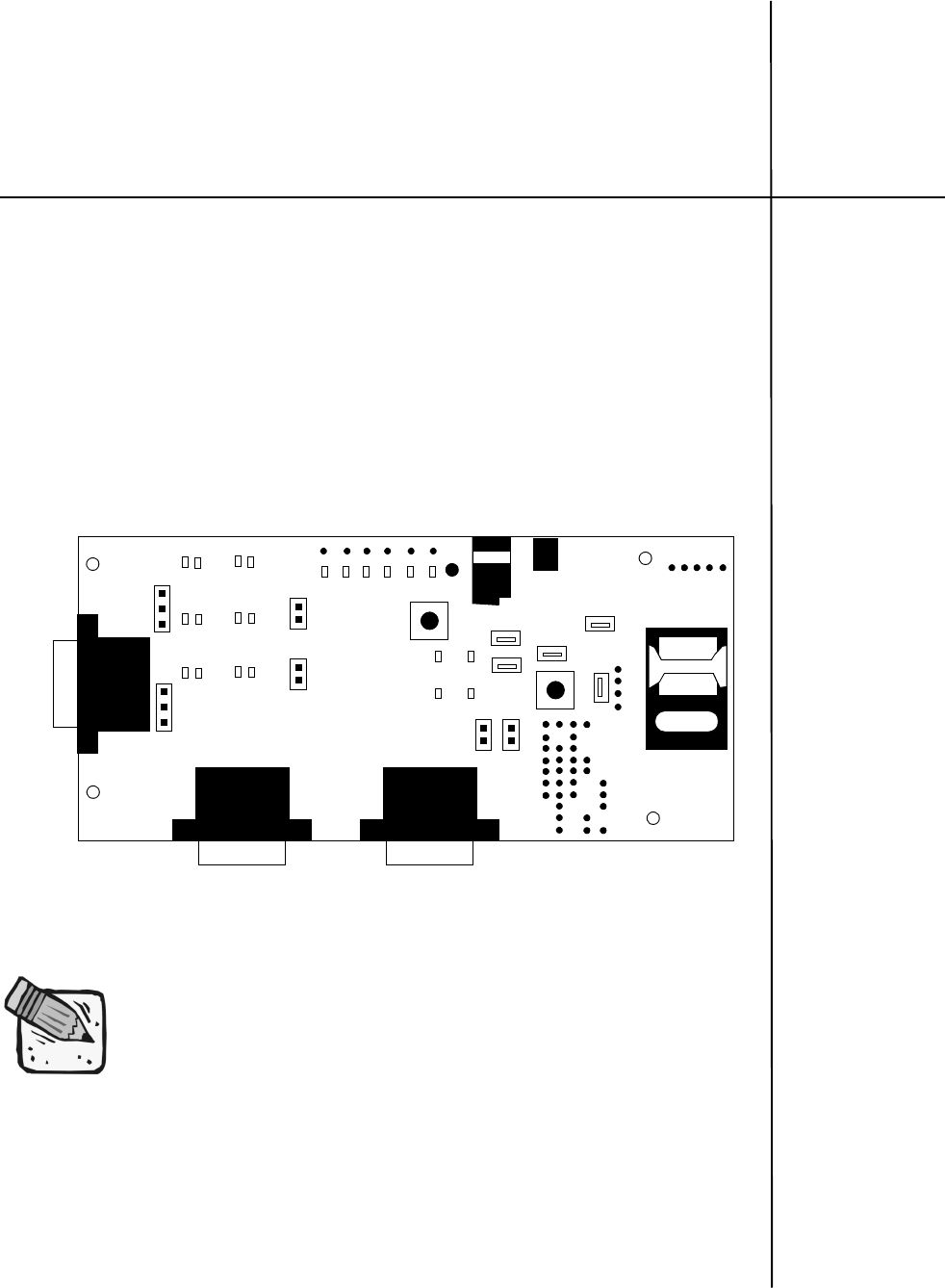
M
M
M
Me
e
e
er
r
r
rl
l
l
li
i
i
in
n
n
n
a
a
a
an
n
n
nd
d
d
d
E
E
E
Ex
x
x
xp
p
p
pe
e
e
ed
d
d
di
i
i
it
t
t
te
e
e
e
Chapter 4: Firmware
Setup and Upgrades
Firmware is installed in all modems prior leaving the manufacturing facility.
Updates to firmware can be performed by downloading new code into the
modem.
Updating Expedite Firmware
To update the Expedite firmware you will require the Expedite Development Kit
Interface Board, shown below . The interface board will connect the Expedite
module to the host computer.
Figure 8: Expedite Development Kit Interface Board
These instructions may change for future product releases.
J106 J105
J107
Test Poi n ts
J3
JP3
JP6
JP10
JP7
JP9 JP1
JP4
JP8
JP5
J15
JP2
SW101
SW100
SIM Card
Topics Included in this Chapter
Updating Expedite Firmware . . . . . . . . . . . . . . . . . . . . . . . . . . . . . . . . . . 145
Updating Merlin Firmware . . . . . . . . . . . . . . . . . . . . . . . . . . . . . . . . . . . . 147
Troubleshooting . . . . . . . . . . . . . . . . . . . . . . . . . . . . . . . . . . . . . . . . . . . . 151
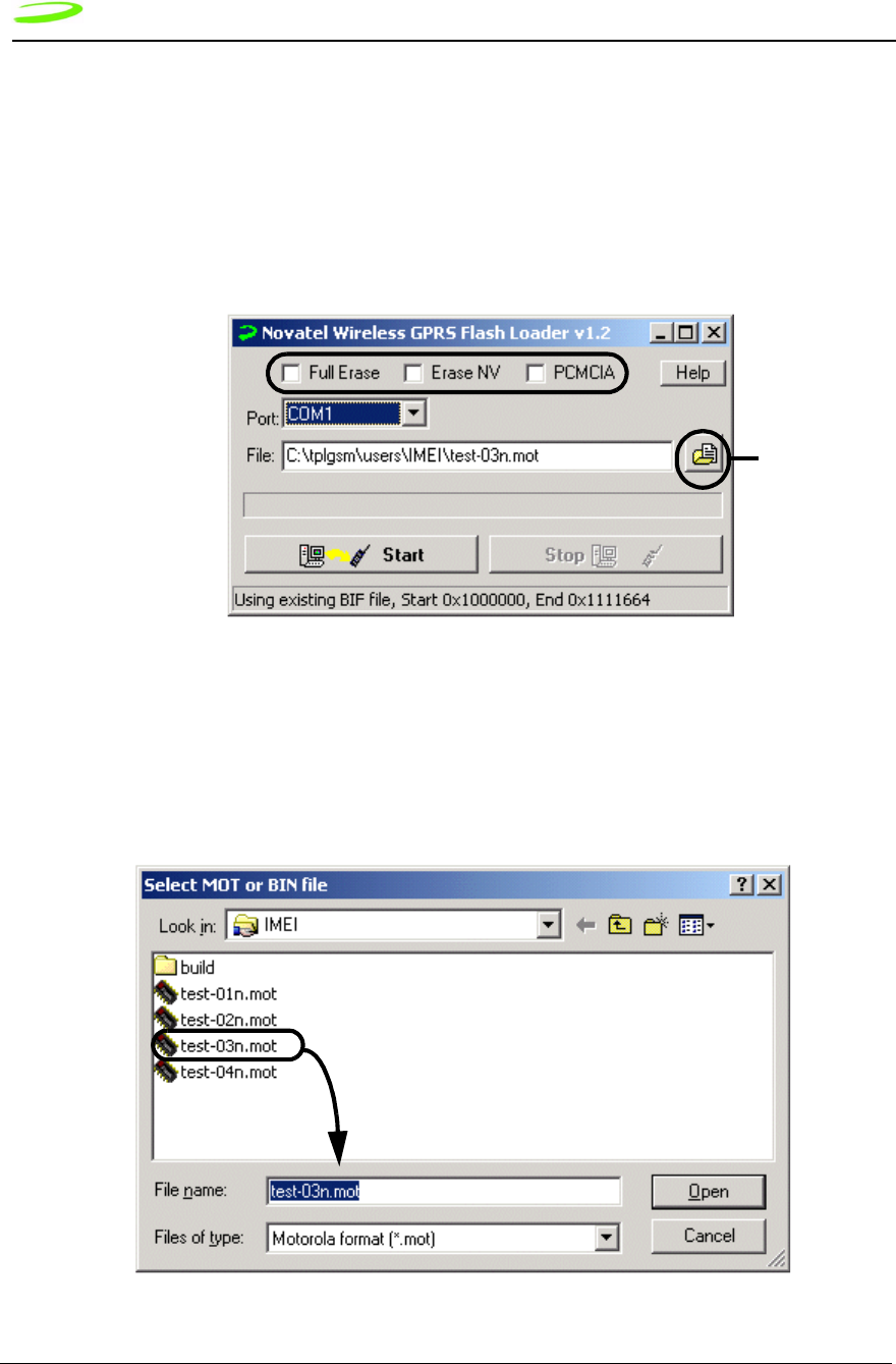
146 Firmware Setup and Upgrades
Revision 1.9 P/N 90023363
To update Expedite firmware:
1. Disconnect the interface board from the power source.
2. Connect the serial cable to the Primary Serial Port (J106) on the Expedite interface
board.
3. Connect the other end of the cable to a port (either 1 or 2, depending on your PC) in
your computer.
4. Start the Flash.exe program.
Figure 9: Flash Program
5. Select the appropriate Erase option. With no options chosen (recommended), the
Flash Loader will do a partial erase.
6. Navigate to and select the binary Motorola™ (.mot) file to download by pressing the
New File button.
Figure 10: Selecting MOT file
New File Button
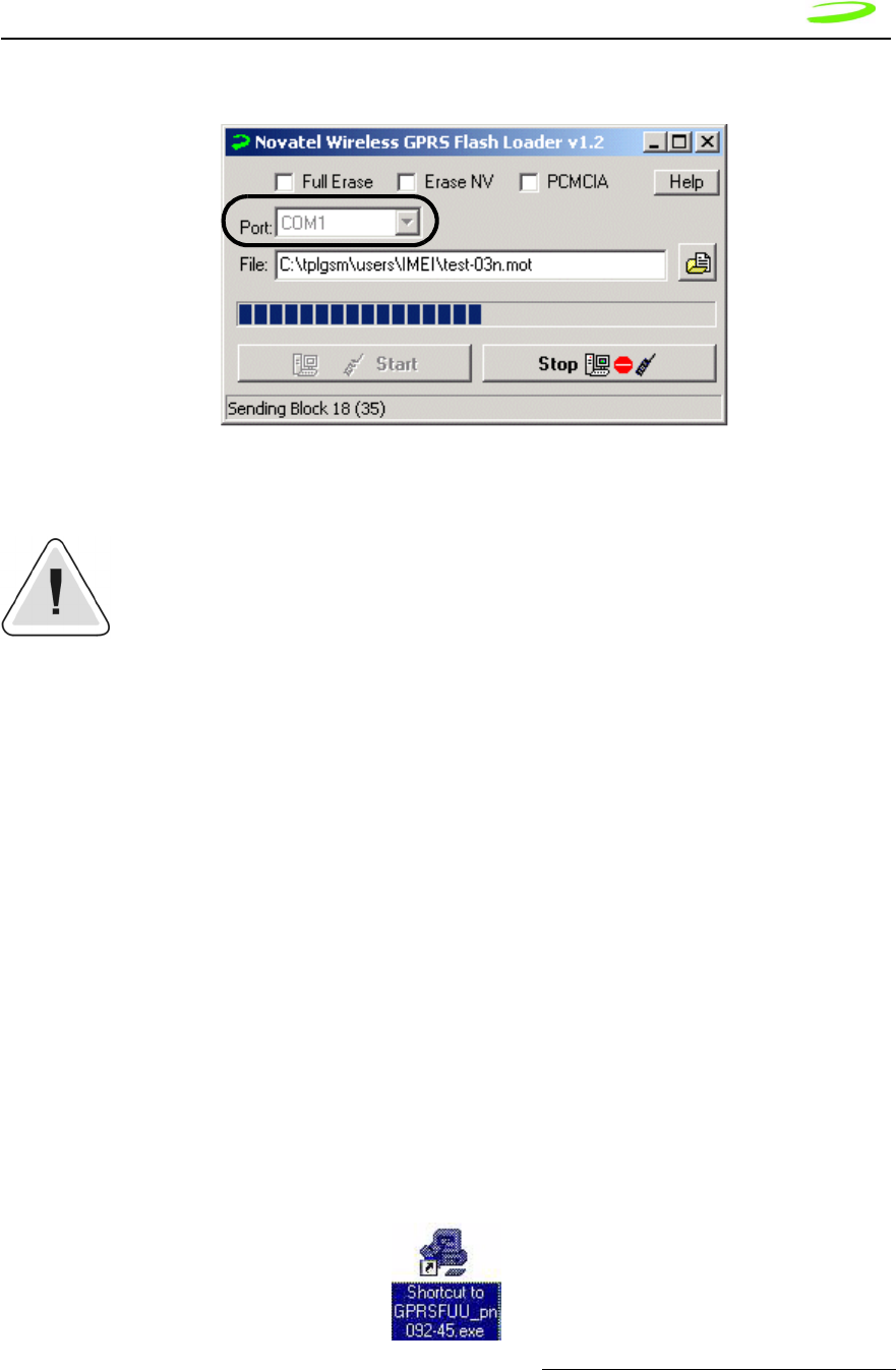
Firmware Setup and Upgrades 147
P/N 90023363 Revision 1.9
7. The default communications port is COM1; select the correct one if necessary.
Figure 11: Flash Loader Settings
8. Press Start. The message “Power On/Reset Target” will appear in the status bar.
Once you start downloading firmware, you cannot stop the process until the
“Download Complete” message is shown on the status bar.
9. Apply power to the device. LED’s on interface board will light up.
10. Disconnect the power supply when the “Download Complete” message appears in
the status bar.
11. Reconnect the power again for regular operation.
Updating Merlin Firmware
The GPRS Firmware Upgrade Utility is used to update Merlin firmware. The utility
program and code is delivered as a self-extracting executable file.
To update Merlin firmware:
1. Obtain the executable file from your service provider, ensuring that you have the
appropriate single band or dual band version. (PN=Single band or North America;
PE=Dual band or European.
2. Ensure that you have at least 10 MB of free disk space on your system drive.
3. Close all applications in order to avoid resource conflicts.
4. Run the Firmware Upgrade Utility by double-clicking the Desktop icon:
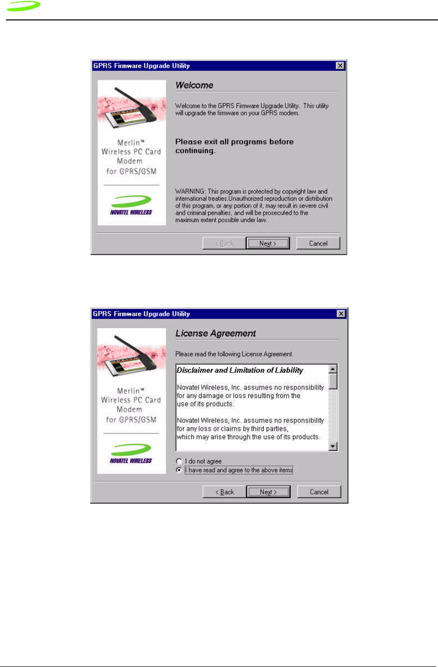
148 Firmware Setup and Upgrades
Revision 1.9 P/N 90023363
5. After the splash window, the Welcome window will be displayed.
6. Read the Welcome window and click Next.The License agreement will be displayed.
7. Read the License Agreement. To continue with the upgrade utility, you must indicate
that you have accepted the terms of the agreement by selecting “I have read and
agree to the above items.” Click Next. The Instructions for Upgrading window will
appear.
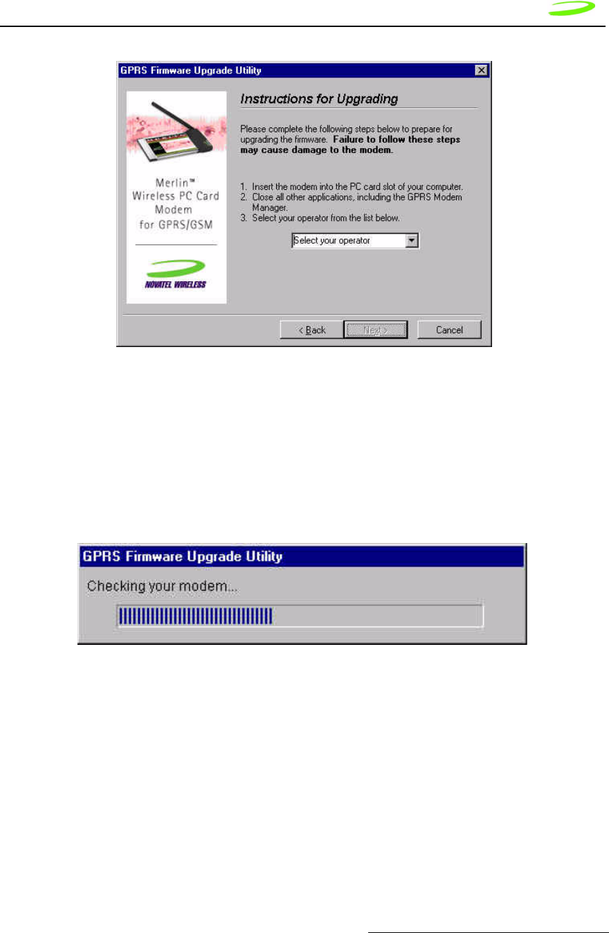
Firmware Setup and Upgrades 149
P/N 90023363 Revision 1.9
7.1. Insert your modem into the PC Card slot.
7.2. Ensure all other applications are closed.
7.3. Select your operator from the drop down menu.
7.4. Click Next.
The utility will then locate your modem for the upgrade. The Checking your modem
window will appear.
If your modem is located, the Start Upgrade window will be displayed.
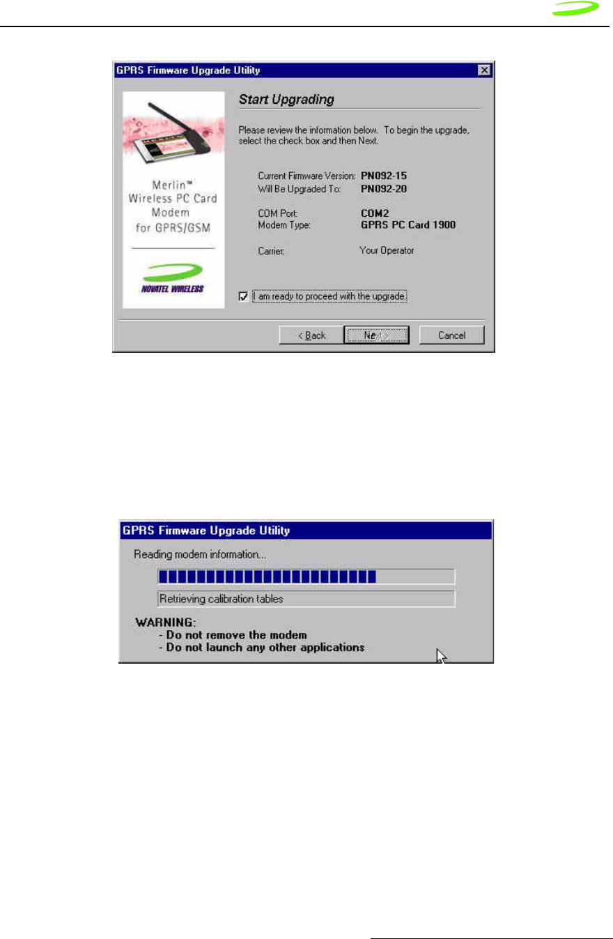
Firmware Setup and Upgrades 150
P/N 90023363 Revision 1.9
8. Ensure all information on the window is correct, then select I am ready to proceed
with the upgrade. and select Next.
An Upgrade Status window will appear, and the upgrade utility will retrieve your modem
information.
NOTE: Do not remove any modem or launch any other applications during the
upgrade.
The upgrade consists of 3 phases:
• Phase 1: Reading modem information
• Phase 2: Upgrading firmware
• Phase 3: Writing Modem information
NOTE: The upgrade process may take up to 10 minutes for completion. Please wait
for the process to complete even if it appears that the utility has stopped.
Once the upgrade is complete, the Upgrade Complete window will appear.
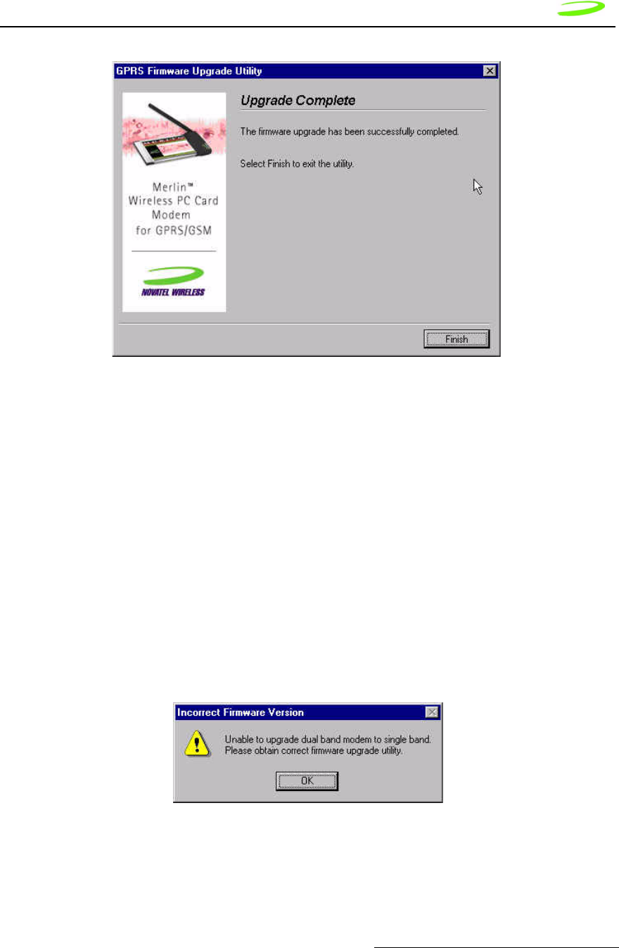
Firmware Setup and Upgrades 151
P/N 90023363 Revision 1.9
9. Select Finish to close the firmware upgrade utility.
NOTE: This utility creates a log file in your Windows temp directory called GPRSFUU.log.
Customer support may request this log if there was a problem upgrading your modem’s
firmware.
Troubleshooting
If there is a problem with the firmware upgrade, a warning window will appear. Follow
the steps below to solve the problem indicated by the warning window.
Incorrect Firmware Version
Dual Band Modem with Single Band Firmware
If the warning below appears, the wrong type of modem has been inserted into the PC slot
of your computer.
You have inserted a dual band modem that requires a firmware type that starts with “PE.”
Please locate and install the correct firmware version.
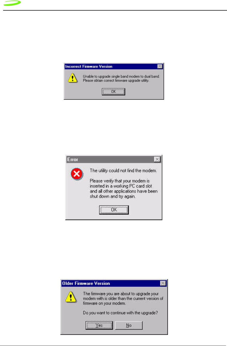
152 Firmware Setup and Upgrades
Revision 1.9 P/N 90023363
Incorrect Firmware Version
Single Band Modem with Dual Band Firmware
If the warning below appears, the wrong type of modem has been inserted into the PC
slot of your computer.
You have inserted a dual band modem that requires a firmware type that starts with “PN.”
Please locate and install the correct firmware version.
Firmware Utility Cannot Locate Modem
If the warning below appears, the Firmware Upgrade Utility cannot locate your modem.
Please ensure that the modem is firmly inserted into the PCMCIA slot. If the error
message reappears, remove your modem and reinsert it into an adjacent slot.
Older Firmware Version
If the warning below appears, the firmware version that you are about to load is older
than the current version of firmware on your modem.

Firmware Setup and Upgrades 153
P/N 90023363 Revision 1.9
If you have been instructed by your operator to perform the upgrade, click Yes. If you
have NOT been instructed to perform the upgrade, select No. This will stop the upgrade
process.

154 Firmware Setup and Upgrades
Revision 1.9 P/N 90023363

M
M
M
Me
e
e
er
r
r
rl
l
l
li
i
i
in
n
n
n
a
a
a
an
n
n
nd
d
d
d
E
E
E
Ex
x
x
xp
p
p
pe
e
e
ed
d
d
di
i
i
it
t
t
te
e
e
e
Chapter 5: Software
Interface
Novatel Wireless™ has designed and developed a protocol which provides
facilities to monitor modem status while a data session on the host is active. In a
modem environment, modem status is typically accessed through AT commands
over the serial port. However, after a data session is activated on the host
through the modem, the serial port is deemed “in-use” and direct serial access
of AT Commands is not permitted. All data is now encapsulated through the data
session protocols.
The following items will be discussed within this chapter:
• wireline modem interface
• wrapper protocol
• pros and cons of the wrapper protocol
Topics Included in this Chapter
Point-to-Point Protocol Interface . . . . . . . . . . . . . . . . . . . . . . . . . . . . . . . 156
Software Architecture . . . . . . . . . . . . . . . . . . . . . . . . . . . . . . . . . . . . . . . 157
Wrapper Protocol Overview . . . . . . . . . . . . . . . . . . . . . . . . . . . . . . . . . . . 158

156 Software Interface
Revision 1.9 P/N 90023363
Point-to-Point Protocol Interface
A Point-to-Point (PPP) server implementation is supported within the GPRS module.
Remote Access Service (RAS) communication over the serial port is supported using the
AT commands to enter the PPP session and support PPP negotiation of IP and DNS
elements.
PPP negotiation will NOT complete until registration on the network has been completed.
In some cases, particularly where dynamic IP addressing is supported by the carrier, this
will not occur as it would be impossible to report an IP address until the unit had
performed the GPRS “attach request” on the network.
Status Interface
The Expedite and Merlin GPRS modem supports a method to retrieve modem status
information using AT commands while the modem is in a data session. This is
accomplished by using a unique driver called a Wrapper driver which exposes two serial
ports, one for data and the other for status. The Wrapper driver multiplexes or “wraps” the
information across the single serial or PCMCIA connection, and the data is then
“unwrapped” and routed to the appropriate location in the modem or over the air. This
allows status requests to occur in a separate stream to permit either the Novatel Wireless
Modem Manager or another user application to communicate with the modem. It is
anticipated that this approach will work for the majority of applications.
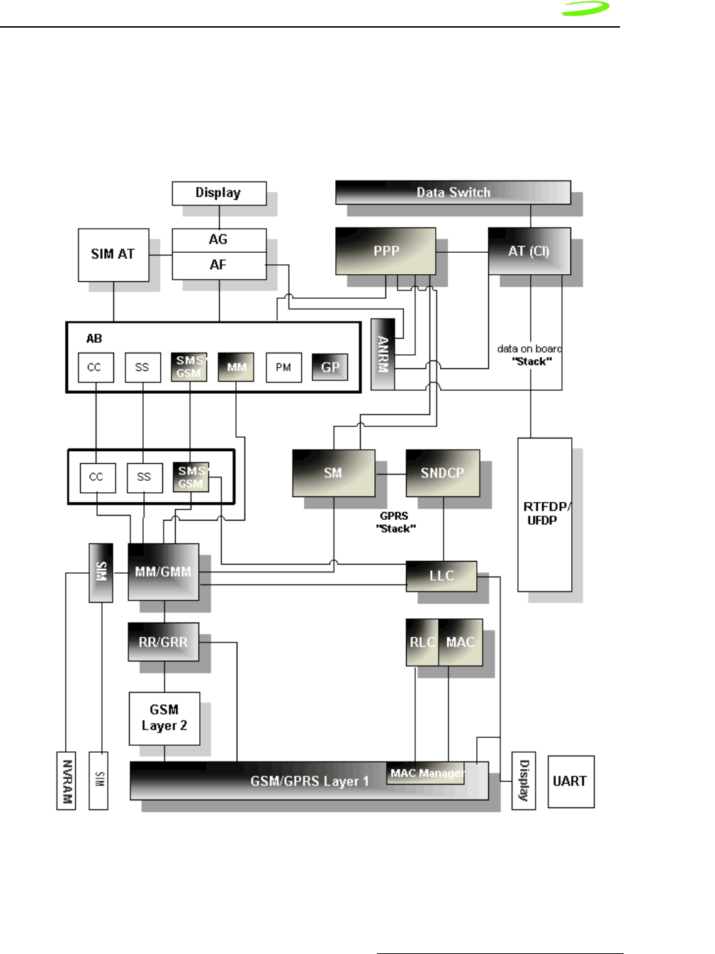
Software Interface 157
P/N 90023363 Revision 1.9
Software Architecture
Figure 12: Software Architecture below depicts the software interfaces for the Novatel GPRS modem
software.
Figure 12: Software Architecture

158 Software Interface
Revision 1.9 P/N 90023363
Wireline Modem Interface
All of the current Merlin based products implement a communication model that emulates
a wireline modem interface.
In a traditional modem model, users:
1. select the appropriate modem from the installation list
2. dial a number using that modem to contact their ISP
3. allow the host stack to establish a PPP session with another network entity.
Wrapper Protocol Overview
Novatel Wireless has created a protocol to provide facilities to monitor modem status
while a data session on the host is active. In a modem environment, modem status is
typically assessed through AT commands over the serial port. However, after a data
session is activated on the host through the modem, the serial port is deemed “in-use”
and direct serial access of AT commands is not permitted. All data is now encapsulated
through the data session protocols. The modem is limited in its processing of the
incoming data stream on the serial port to either passing the data along (as in a data
session) or processing it internally (as in AT commands).
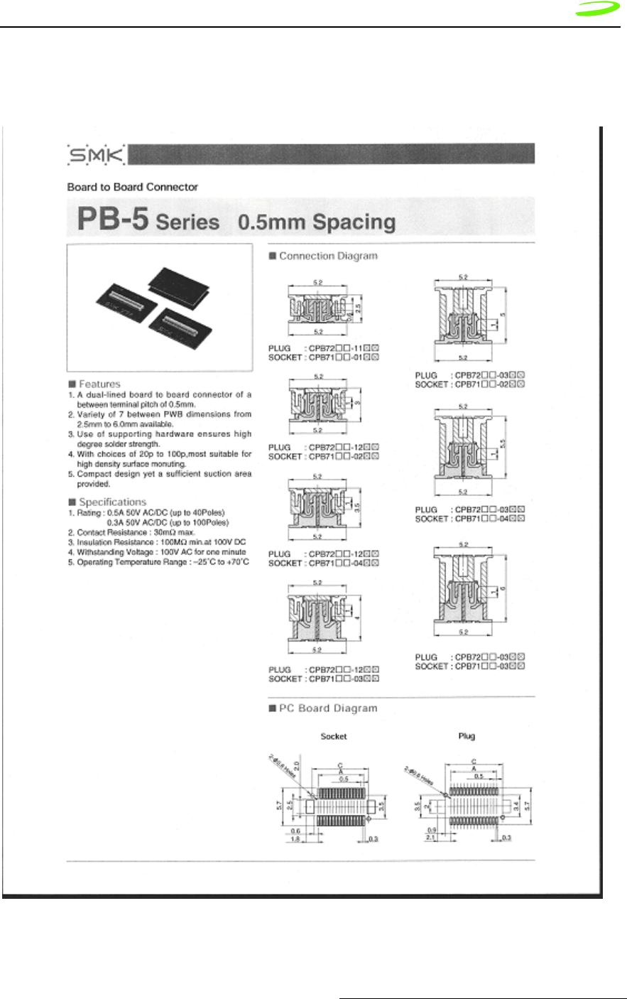
Appendix A - Expedite Connectors 159
P/N 90023363 Revision 1.9
Appendix A - Expedite Connectors
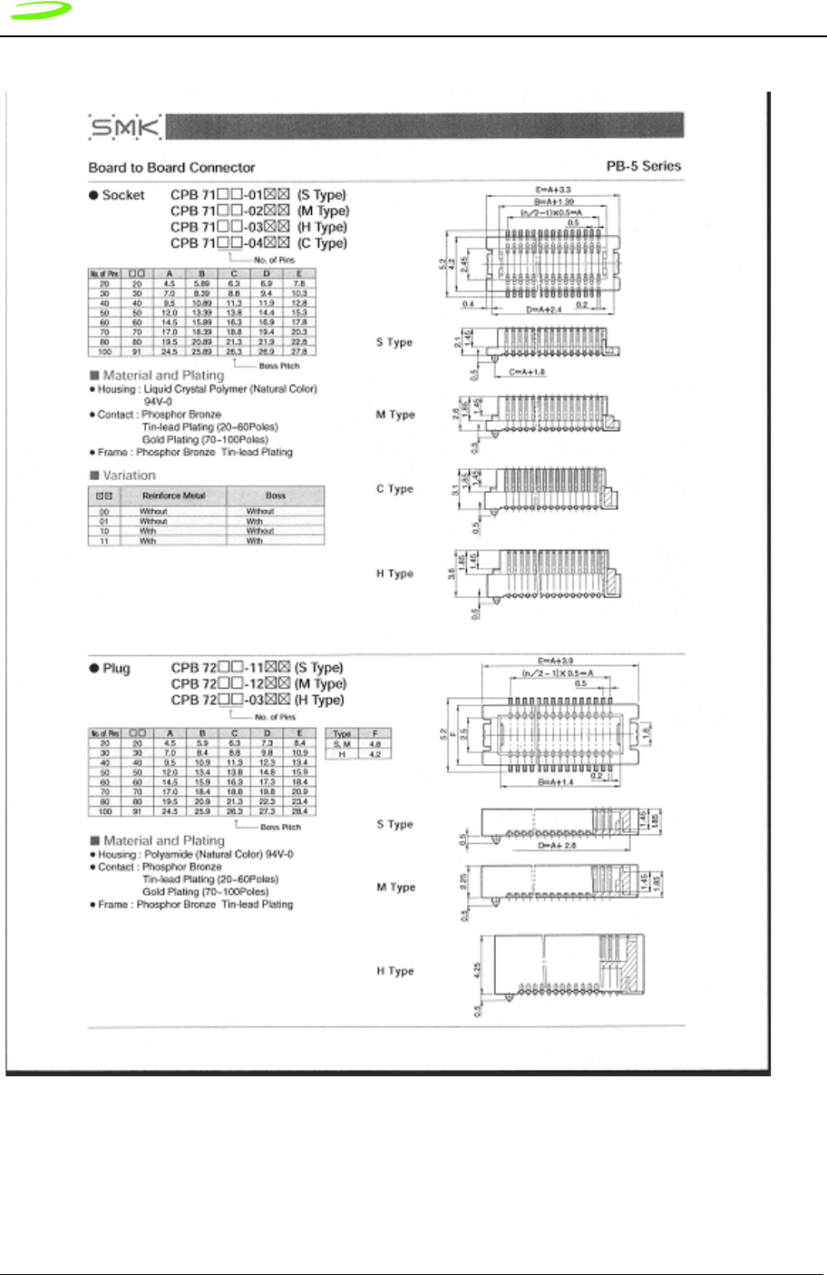
160 Appendix A - Expedite Connectors
Revision 1.9 P/N 90023363
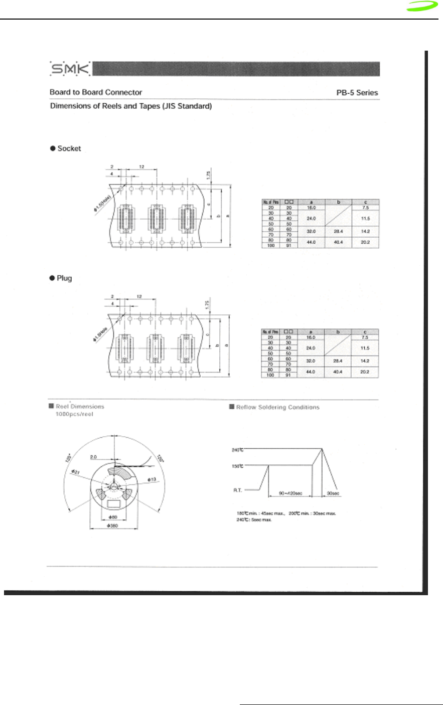
Appendix A - Expedite Connectors 161
P/N 90023363 Revision 1.9
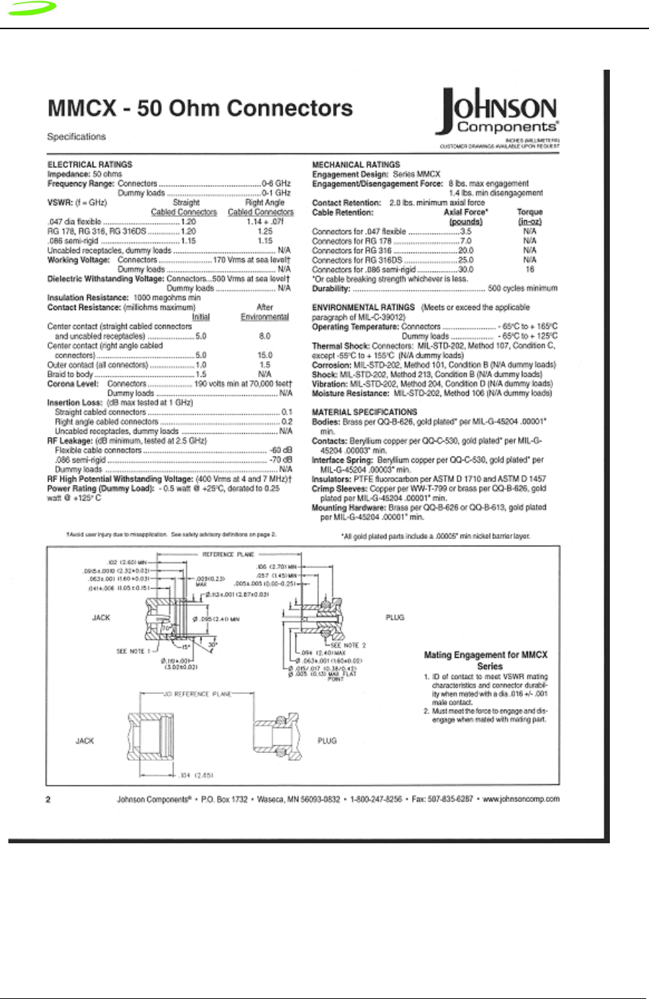
162 Appendix A - Expedite Connectors
Revision 1.9 P/N 90023363

Appendix A - Expedite Connectors 163
P/N 90023363 Revision 1.9
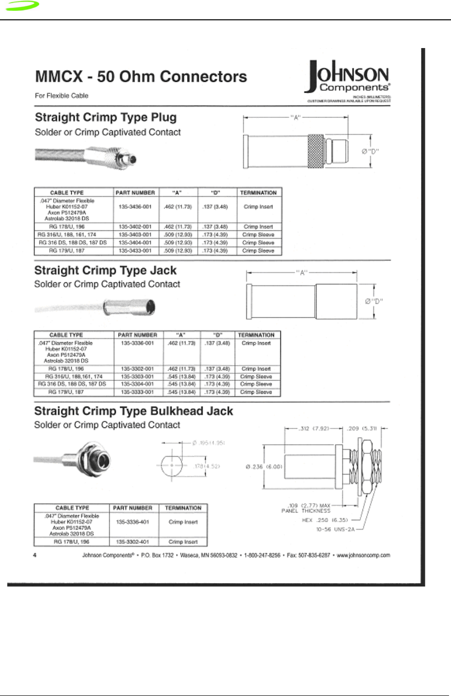
164 Appendix A - Expedite Connectors
Revision 1.9 P/N 90023363
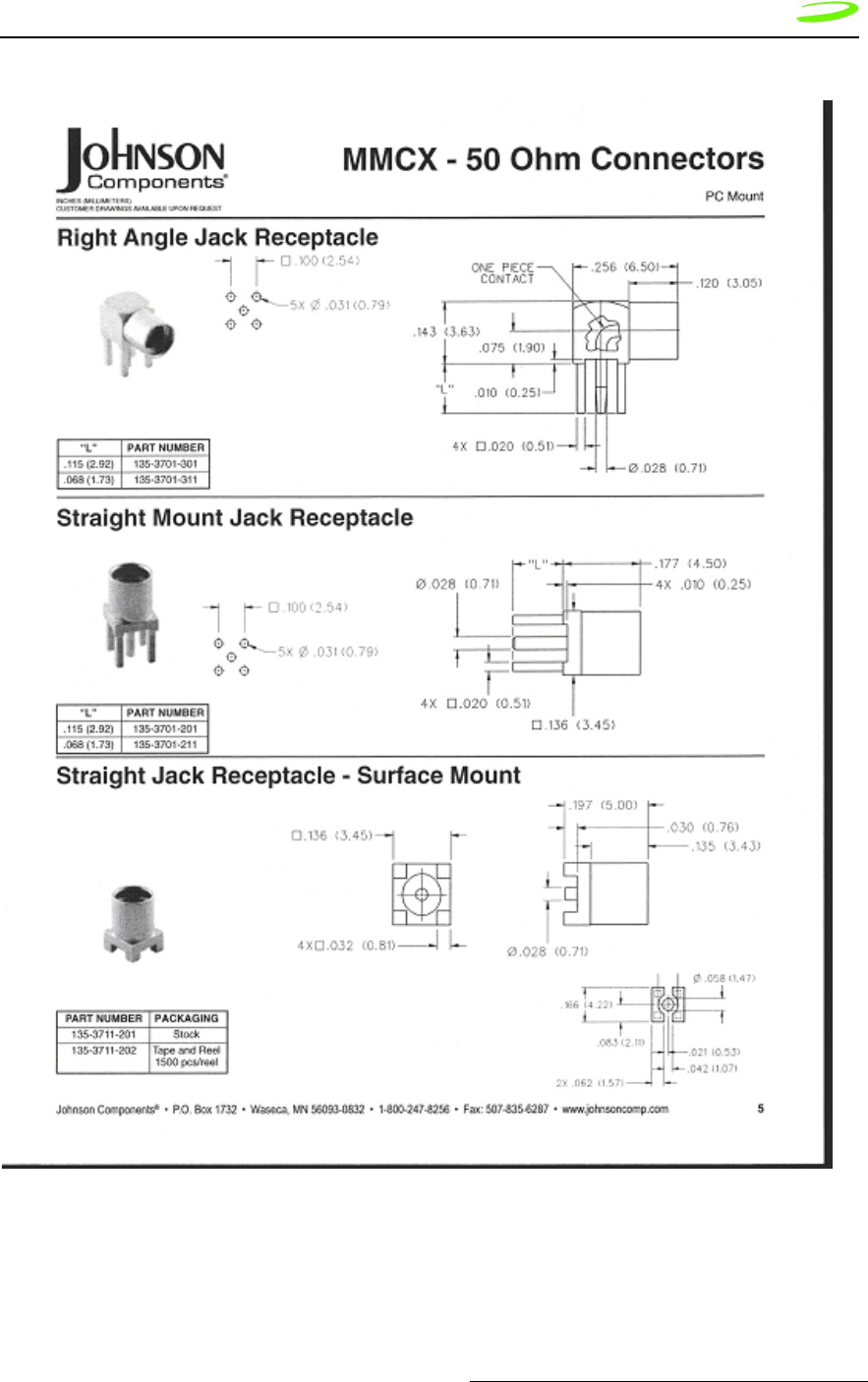
Appendix A - Expedite Connectors 165
P/N 90023363 Revision 1.9
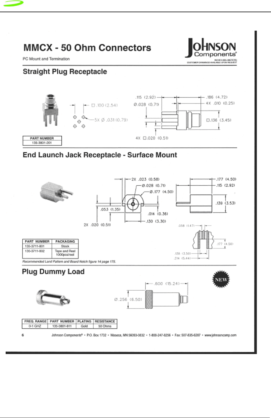
166 Appendix A - Expedite Connectors
Revision 1.9 P/N 90023363
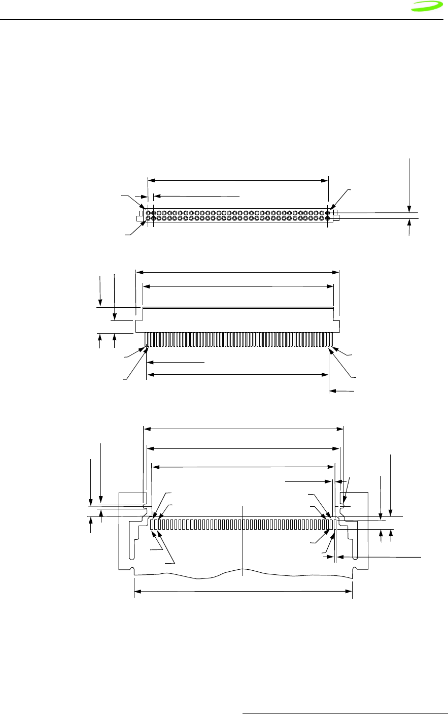
Appendix B - Merlin Connectors 167
P/N 90023363 Revision 1.8
Appendix B - Merlin Connectors
Merlin G100 Connectors
Figure 13: G100 68 Pin Connector
1.27 +/- 0.1 (PITCH)
41.4 +/- 0.15
No. 68
(No. 01)
No. 34
(No. 35)
No. 35
(No. 34)
No. 01
(No. 68)
6.0 +/- 0.1
3.0 +/- 0.1
47.4 +/- 0.2
44.4 +/- .15
0.28 +/- .01
(0.635 x 67 = 42.545)
No. 68
(No. 01)
No. 34
(No. 35)
No. 35
(No. 34)
No. 01
(No. 68)
ITT CANNON 127040-2414 S925
46.6 +/- 0.05
44.8
#01
#02
#34
#33
#35
#36
#67
#68
50.5
RECOMMENDED PCB FOOTPRINT
1.2 +/- 0.1
2.2
3.15 +/- 0.05
67 x 0.635
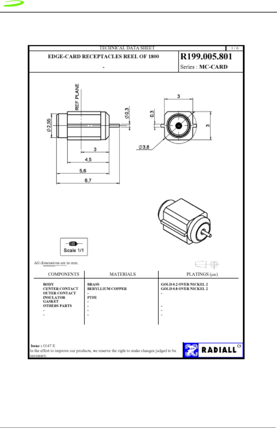
168 Appendix B - Merlin Connectors
Revision 1.8 P/N 90023363
Figure 14: G100 Radiall RF Connector
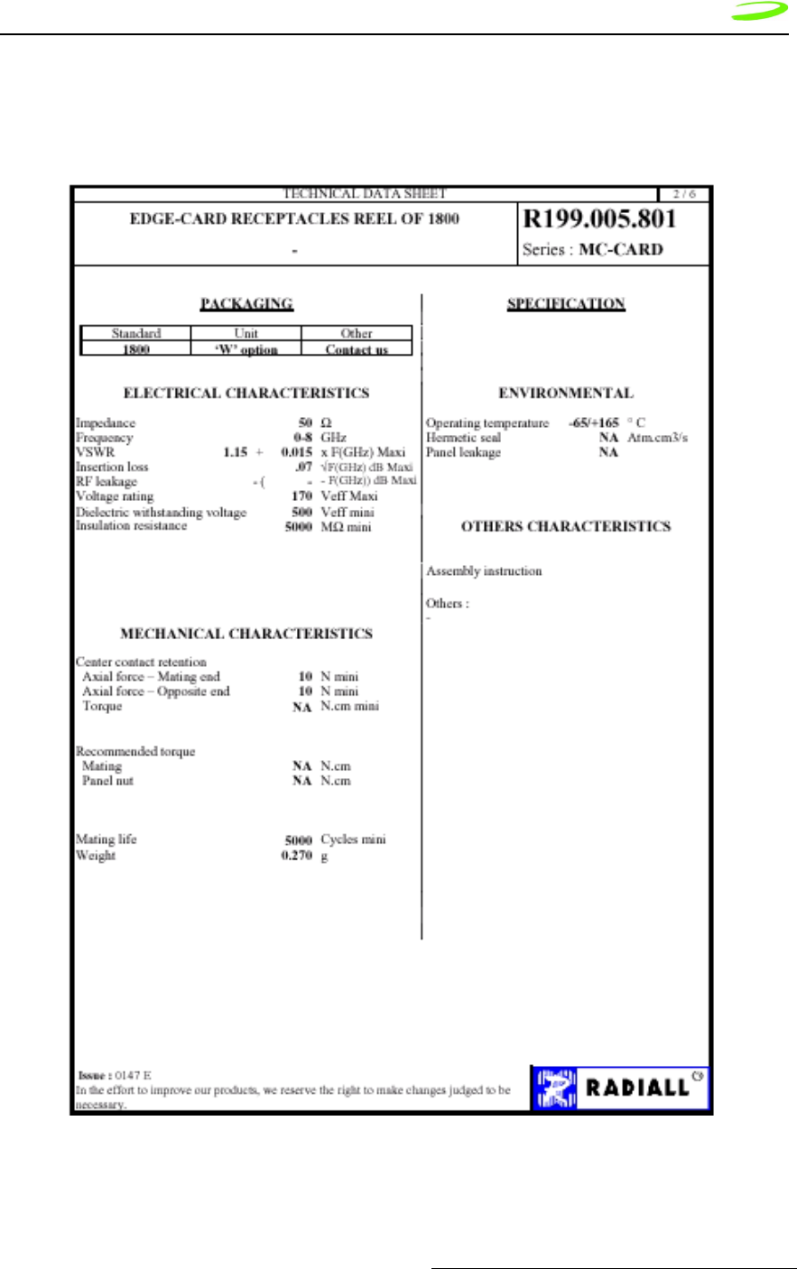
Appendix B - Merlin Connectors 169
P/N 90023363 Revision 1.8
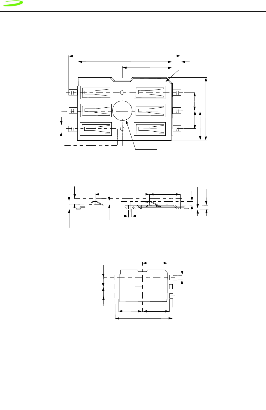
170 Appendix B - Merlin Connectors
Revision 1.8 P/N 90023363
Figure 15: G100 SIM Connector
15.7 +/- 0.2
13.3 +/- 0.1 1.2
7 +/- 0.1
0.8
2.54 +/- 0.1
2.54 +/- 0.1
4.15 +/- 0.1
8.8 +/- 0.1
VACUUM AREA
7.62 +/- 0.2 4.28 +/- .15
(0.4)
3 -- 0.5 +/- .08
0.05 +/- .05
0.53
STAND OFF
(0.55)
0.5 +/- .1 0.55 +/- .1
CONTACT
SHOULDER
THICKNESS
HEIGHT
+/- 0.76
2.54 +/- .05 2.54 +/- .05
16.2 +/- .05
6.8 +/- .05 7.5 +/- .05
7 +/- .05
6 - 1.3 +/- .05
APPLICABLE P.C.B. DIMENSION (REF.)
0.8
+/- 0.1
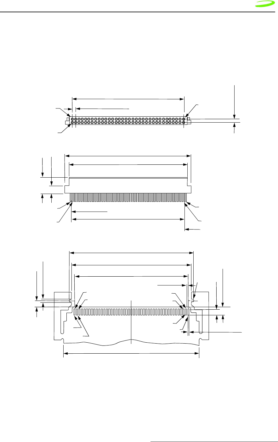
Appendix B - Merlin Connectors 171
P/N 90023363 Revision 1.8
Merlin G200 Connectors
Figure 16: G200 68 Pin Connector
1.27 +/- 0.1 (PITCH)
41.4 +/- 0.15
No. 68
(No. 01)
No. 34
(No. 35)
No. 35
(No. 34)
No. 01
(No. 68)
6.0 +/- 0.1
3.0 +/- 0.1
47.4 +/- 0.2
44.4 +/- .15
0.28 +/- .01
(0.635 x 67 = 42.545)
No. 68
(No. 01)
No. 34
(No. 35)
No. 35
(No. 34)
No. 01
(No. 68)
ITT CANNON 127040-2414 S925
46.6 +/- 0.05
44.8
#01
#02
#34
#33
#35
#36
#67
#68
50.5
RECOMMENDED PCB FOOTPRINT
1.2 +/- 0.1
2.2
3.15 +/- 0.05
67 x 0.635
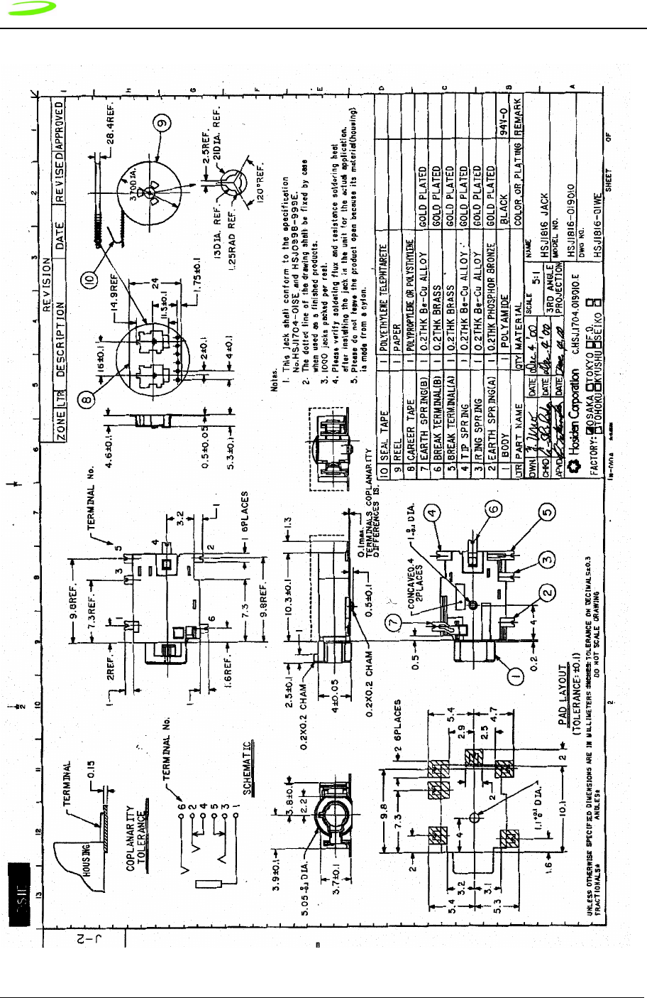
172 Appendix B - Merlin Connectors
Revision 1.8 P/N 90023363
Figure 17: G200 Audio Jack

Appendix B - Merlin Connectors 173
P/N 90023363 Revision 1.8
Figure 18: G200 RF Connector
SUHNER
COAXIAL CONNECTOR DATA SHEET
WAIVER!
While the information contained in this folder has been carefully compiled to the best of our present knowledge,
it is not intended as representation or warranty of any kind on our part regarding the fitness of the products
concerned for any particular use or purpose and neither shall any statement contained herein be constructed as
a recommendation to infringe any industrial property rights or as a license to use any such rights. The fitness of
each product for any particular purpose must be checked beforehand with our specialists.
Issued: 10.3.2000 15:49 Document No.: 22649679A.DOC
Uncontrolled copy page 1 of 1
HUBER+SUHNER AG
RF Interconnections
CH-9100 Herisau
Phone +41 (0)71 353 41 11
Fax +41 (0)71 353 45 90
http://www.hubersuhner.com
TYPE 82 MMCX-S50-0-2
Description
Straight PCB jack
General Information
Interface according to: SUHNER® MMCX
Weight: 0.7 g /
0.02 oz
Electrical Data Impedance: 50 Ω
Frequency range for connector interface: DC ... 6.0 GHz
Material Data Material Surface Plating
Centre contact: Copper-Beryllium Gold / nickel underplated
Outer contact: Brass Gold / nickel underplated
Body: Brass Gold / nickel underplated
Insulator: PTFE / PFA
Coupling nut: -
Fastening nut: -
Gasket: -
Washer: -
Packaging Tape and Reel
Attachments Outline drawing No.: 21471
Assembly instruction:
Notes
-
Order as 82 MMCX-S50-0-2/111 KG under Article No. 22649679
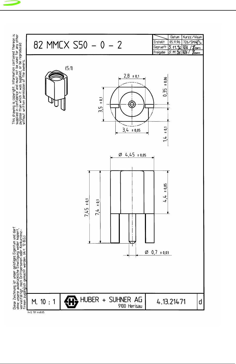
174 Appendix B - Merlin Connectors
Revision 1.8 P/N 90023363
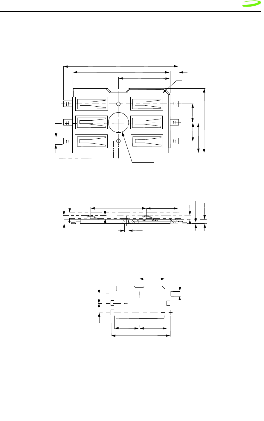
Appendix B - Merlin Connectors 175
P/N 90023363 Revision 1.8
Figure 19: G200 SIM Connector
15.7 +/- 0.2
13.3 +/- 0.1 1.2
7 +/- 0.1
0.8
2.54 +/- 0.1
2.54 +/- 0.1
4.15 +/- 0.1
8.8 +/- 0.1
VACUUM AREA
7.62 +/- 0.2 4.28 +/- .15
(0.4)
3 -- 0.5 +/- .08
0.05 +/- .05
0.53
STAND OFF
(0.55)
0.5 +/- .1 0.55 +/- .1
CONTACT
SHOULDER
THICKNESS
HEIGHT
+/- 0.76
2.54 +/- .05 2.54 +/- .05
16.2 +/- .05
6.8 +/- .05 7.5 +/- .05
7 +/- .05
6 - 1.3 +/- .05
APPLICABLE P.C.B. DIMENSION (REF.)
0.8
+/- 0.1

176 Appendix B - Merlin Connectors
Revision 1.8 P/N 90023363
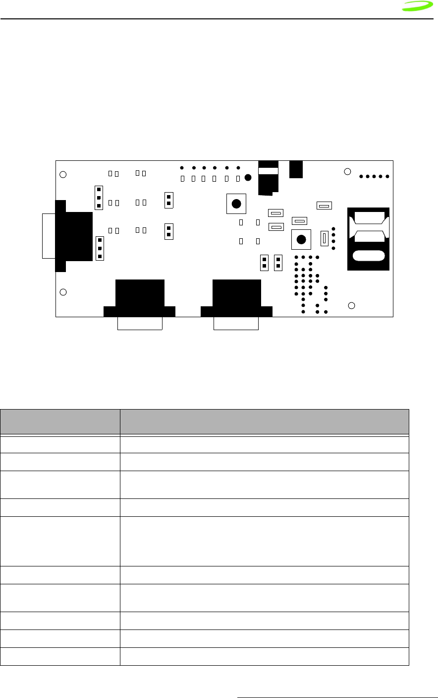
Appendix C – Expedite Development Kit Interface Board 177
P/N 90023363 Revision 1.9
Appendix C – Expedite Development Kit
Interface Board
The Expedite Development Kit is used to develop applications for embedding GPRS
capability into OEM products and for upgrading firmware.
Figure 1: Expedite Development Kit Interface Board
Table 1: Interface Board Connector Assignment
Point Name Function
JP1 & JP9 ADC Input pin – monitors ADC Battery Voltage
JP2 or SIM_IN Activates switch on PC card
JP6 Allows debugging to either J107 (jumper on pins 2 and 3) or not (jumper on pins
1 and 2). GPIO6 LED turns on during transmission regardless.
JP5 & JP15 Always enable jumpers; used for current measurements.
JP7 & JP10 Jumper must be placed on either JP10 (primary serial port) or JP7 (USC) to dis-
able serial port (i.e.: jumper on JP7 disables USC).
NOTE: printing error on interface card – should read DIS_PRM for JP10 and
DIS_USC for JP7.
JP8 Wake up hardware button
JP3 Allows debugging to either J107 (jumper on pins 2 and 3) or to GPIO4 LED
(jumper on pins 1 and 2)
JP108 Voltage bench box supply
JP4 Ground
J3 5 V power supply.
J106 J105
J107
Test Po ints
J3
JP3
JP6
JP10
JP7
JP9 JP1
JP4
JP8
JP5
J15
JP2
SW101
SW100
SIM Card

J104 Place SIM card here
SW100 Wakeup button (press for 750 ms to wake up device). Jumper on pins above
SW100 enable software download without having to manually press button.
SW101 Testing purposes.
Power supply should vary between 3.8 – 4.5 Volts. DO NOT EXCEED
4.5 V.

Glossary 179
P/N 90023363 Revision 1.9
Glossary
Access Point Name (APN)
The IP domain name (e.i. Novatel Wireless.com) of the network device that acts as a
gateway by connecting a GPRS wireless radio network to a wired local or wide area
network.
Active Network Session
An active network session allows you to send and receive data across the Internet
using point-to-point protocol through your network connection.
Anonymous Access (AA)
Network does not know the real identity of the mobile. Opposite to non-anonymous.
AP Access Point
An entry point to an external network.
AT Commands
AT commands are a language type that enables PC communications software to give
the modem directions. The term AT comes from the command terminology which
always begins with attention, or AT.
Baud Rate
The actual bit rate, excluding compression and other Tx enhancements, on a
communication line.
Border Gateway (BG)
Logical box that connects two (or more) operators together via an Inter-PLMN
backbone. BG protects operator’s intra-PLMN network against intruders.
Carrier
See Service Provider on page 183.
Circuit Switched Data
A wireless network connection established, using a single circuit that extends from you,
directly through the network to your call’s destination. Opposite to packet switched.
This connection type is also referred to as GSM-Data.
CLI
Command Line Interface.
CLIR
Call Line Identification Restriction.
Connection Oriented Network Service (CONS)
Same as X.25 protocol for packet network transmission and switching.
CSD
See “Circuit Switched Data” on page 179.

180 Glossary
Revision 1.9 P/N 90023363
Connection Profile
See Network Connection Profiles on page 182.
dBm
dBm stands for decibels below 1 milliwatt. It is essentially a device’s signal output power
compared against a standard input signal strength of 1 (one) milliwatt. This number
represents a ratio and is expressed as a negative number (e.i. -60dBm)
Default Network Connection Profile
The default network connection profile is the connection profile, chosen by the user, that
the Modem Manager will use to connect to the network. The default network connection
profile can be thought of as the active network connection profile.
Direct Memory Access (DMA)
A fast method of moving data from a storage device or LAN device interface card directly
to RAM which speeds up processing. DMA by passes the CPU.
Domain Name
The name assigned to a computer or group of computers that constitute an IP network
domain. In general, a domain name is comprised of its local host name and its top-level
domain. The top-level domain can be made up of several names, each separated by a
period (.).
An example of a domain name is novatelwireless.com.
Domain Name System (DNS)
This is a network server used on IP networks, such as the Internet, for translating network
host names and Universal Resource Locators (URL’s) into IP addresses.
Domain Name System (DNS) Address
The IP (internet protocol) address of the Domain Name System (DNS).
Firmware
Firmware is a program or set of programs that have been set permanently into a computer
chip. The programs themselves usually are low-level programs that directly manipulate or
interact with the hardware. An example of firmware is your desktop computer’s BIOS.
Gateway GPRS Support Node (GGSN)
The SGSN communicates with what is called the Gateway GPRS Support Node (GGSN),
a system that maintains connections with other networks such as the Internet, X.25
networks or private networks.
GPRS
GPRS stands for General Packet Radio Service. GPRS is a high-speed data transfer
technique, used on GSM networks. It does not require that a continuous data stream be
opened between the data source and destination. Instead, it uses packet to move data
back and forth, making efficient use of the available radio spectrum.
GPRS Mobility Management and Session Management (GMM/SM)
Protocol stack between MS and SGSN that handles GPRS attach/detach and PDP context
activation/deactivation.

Glossary 181
P/N 90023363 Revision 1.9
GPRS Tunnelling Protocol (GTP)
Protocol between SGSN and GGSN to encapsulate user data and to carry GPRS
signaling.
GSM
GSM stands for Global System for Mobiles. It is an open, non-proprietary system with
international roaming capability providing seamless and same standardized same
number contact ability in more than 170 countries. GSM satellite roaming has extended
service access to areas where terrestrial coverage is not available.
GSM uses digital technology and time division multiple access transmission methods.
Voice is digitally encoded via a unique encoder, which emulates the characteristics of
human speech. This method of transmission permits a very efficient data rate/
information content ratio.
GSM-Data
See “Circuit Switched Data” on page 179.
Home Public Land Mobile Network (HPLMN)
The home network.
IMEI
IMEI stands for International Mobile Station Equipment Identity.
Internet Protocol (IP)
Internet Protocol works in conjunction with Transmission Control Protocol (TCP). TCP/
IP are part of a group of protocols that provide communication across interconnected
networks. TCP/IP is the protocol used on the Internet. The TCP protocol first
establishes a connection between the two systems in order to send and receive data,
and then breaks and sequentially marks the message into small packets. The IP
protocol routes and sends the packets based on the IP address.
Internet Control Message Protocol (ICMP)
IP network control protocol.
IP Addresses
As with personal computers that access the Internet, modems using GPRS technology
also have a dedicated Internet Protocol (IP) address, which is used to identify the node
or access point for the modem on the Internet. The service provider assigns this IP
address.
The 32-bit host address is usually represented in dotted decimal notation, e.g.
128.121.4.5. The address can be split into a network number (or network address) and
a host number unique to each host on the network and sometimes also a subnet
address.
IP Network
A network of computer networks that employ Internet Protocol allowing a user to
access the Internet, provided that the user has a modem; telephone line, cable line, or
wireless data network (e.g. CDPD); and a service provider.

182 Glossary
Revision 1.9 P/N 90023363
Local Area Network (LAN)
A computer network that spans a relatively small area (typically up to a 1 km radius),
although most LANS are confined to a single building or group of buildings. This type of
networking allows for easy interconnection of terminals, printers, and computers within a
building or buildings.
Logical Link Control (LLC)
Protocol layer between MS and SGSN.
Medium Access Control (MAC)
Protocol in the radio level that is used to allocate the radio channel.
Megahertz (MHz)
One million hertz. Hertz is another word for cycles in a radio frequency.
Network Connection Profiles
A network connection profile is a group of connection settings that define a specific
network connection to the Modem Manager. This includes such settings as network ID,
network password, APN, DNS addresses and so on.
Mobile Station (MS)
The device being used to receive/transmit data and/or voice.
Original Equipment Manufacturer (OEM)
The original manufacturer of a pieces of equipment, typically complete boards, duplexers
or enclosures etc.
Packet
A short block of data transmitted across a network.
Packet Control Unit (PCU)
Functional element in BSS that handles upper level GPRS control in the radio.
Packet Data Network (PDN)
Network that carries user data in packets. e.i Internet and X.25
Packet Size
The size of a packet expressed in bytes.
PC Card
A PC Card, similar in size to a credit card, is used for adding devices on to portable
computing devices such as laptop, handheld, and palmtop computers. Some examples of
these devices are modems, network cards, disk drive adapters, and extra memory. PC
cards are often called PCMCIA cards.
PCMCIA Card Slots
The PCMCIA card slots are the sockets in the computing device, in which the PCMCIA
card is inserted. It is the hardware interface between the computing device and the
PCMCIA card.

Glossary 183
P/N 90023363 Revision 1.9
Point to Multipoint (PTM)
Widely used protocol under IP to connect. i.e PC and ISP via modems.
Point to Point (PTP)
One sender on receiver.
Point-to-Point Protocol (PPP)
PPP is an interconnection protocol which allows a device, such as a wireless IP
modem, to connect to a network or the Internet.
Primary Domain Name System
In order to get the translated IP addresses, the modem will try to connect to the server
with the primary DNS address. If the modem cannot connect to this address, it will try
to connect using the secondary DNS address.
Protocol Data Unit (PDU)
One data packet.
Quality of Service (QoS)
Definition of the service class of the connection between MS and the network.
Routing Area (RA)
A set of cells that belongs to one group. RA is always a subset of an LA (Location
Area).
Registration
In order to send and receive data across a given network, a GPRS modem must first
register to GSM/GPRS network. This involves the selection of an available channel and
interaction with various systems on the GPRS network to set up a communication path.
Remote Access Service (RAS)
Software that enables distant PCs and workstations to get into a Remote Access
Server to retrieve software and/or data on a corporate LAN. This service is provided
through modems, analog telephone lines or digital ISDN lines.
Request to Send (RTS)
A control signal that has a dedicated wire in the RS-232 protocol. When the far device
places a logic “one” or 5-V voltage on this wire, it enables the near modem to initiate
a transmission.
Secondary Domain Name System
If the modem cannot connect to the DNS using the primary address, it will try to connect
using the secondary DNS address.
Segment
Each IP network address consists of four numeric segments, which are divided by a
period ("."). For example, 204.119.63.40.
Service Provider
A company that provides network connections to the Internet.

184 Glossary
Revision 1.9 P/N 90023363
Short Message Service (SMS)
Short messages either in binary (160 characters) or text messages (140 bytes) format.
SIM
The term SIM stands for Subscriber Identity Module.
SIM Card
A SIM card is a type of smart card that contains all of your account information for your GSM and
GPRS account. It also used to encrypt the data and voice that is sent across the network during a
session.
SIM Card Contact Points
These are the small gold- or aluminum-colored.
Serving GPRS Support Node (SGSN)
The SGSN is the node within the GSM infrastructure that sends and receives data to and
from the mobile stations. It also keeps track of the mobiles within its service area.
Transmission Control Protocol (TCP)
Protocol layer on top of conventional IP protocol.
Type II PCMCIA Card
A Type II PCMCIA card is identical to the Type I PCMCIA card in all ways except that it is
thicker than the Type I card. The Type II PCMCIA card is in general use now.
User Datagram Protocol (UDP)
Another protocol on top of IP.
Wireless IP Network
A wireless network (e.g. GPRS) that uses Internet Protocol (IP).

185
P/N 90023363 Revision 1.9
Index
Symbols
.mot ..................................................................146
Numerics
5-Volt 8-bit I/O memory card .............................. 22
A
Application Information....................................... 41
AT Command Set, by name ...............................53
AT Command, by function .................................. 44
AT commands .................................................... 43
Attach Request ................................................. 156
C
Circuit Switched.................................................. 40
Comma dial modifier .......................................... 70
F
Firmware .......................................................... 145
Firmware, GPRS Update Utility........................ 147
Flash Loader Settings ...................................... 147
G
GPRS ................................................................... 1
I
IP Status Interface ............................................ 156
N
Nonconformities ................................................. 12
O
OEM Monitoring Task ....................................... 156
P
Point-to-Point (PPP) ......................................... 156
R
Radio Channel Frequency............................22, 38
Radio Power Index .......................................23, 39
Remote Access Service (RAS) ........................ 156
S
SIM Card Contacts ............................................. 39
SIM Card Specifications ..................................... 39
SIM Card, use .................................................... 39
Sleep ..................................................................40
SMS Messaging ................................................. 40
Standby .............................................................. 41
Status ............................................................... 156

186
Revision 1.9 P/N 90023363