Novatel Wireless NRMUNDP-1D UNDP-1PCI EXPRESS MINI CARD User Manual XFR D630 Service Manual
Novatel Wireless, Inc. UNDP-1PCI EXPRESS MINI CARD XFR D630 Service Manual
Contents
User Manual 1
December 2008
Dell™ Latitude™ E6400 XFR
Setup and Features Information
WARNING: A WARNING indicates a potential for property damage, personal injury,
or death.
CAUTION: A CAUTION indicates either potential damage to hardware or loss of data and tells
you how to avoid the problem.
NOTE: A NOTE indicates important information that helps you make better use of your
computer.
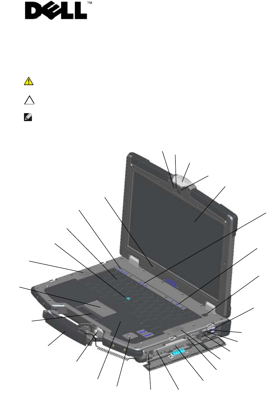
Front View
1
2
3
4
5
6
7
8
9
10
11
12
13
14
15
17
18
19
21
20
23
22
24
25
26
27
28
16
Dell
™
Latitude™ E6400 XFR Setup and Features Information
Page 2
01/08/09
1 Microphone 2 Camera light (optional)
3 Display latch and release 4 Camera (optional)
5 DirectVue™ Outdoor-Readable Display
(optional touchscreen) 6 Keyboard status lights
7 Volume control buttons 8 Power button
9 USB connectors (2) 10 Wi-Fi Catcher™ Network Locator
11 Wireless switch 12 Audio connectors (2)
13 Right speaker 14 SIM card reader
15 Media bay (with optical drive) 16 PC or PC-Express card slot (base dependent)
17 IEEE 1394a connector 18 Fingerprint reader (optional)
19 Contactless smart-card reader (see Smart
Cards)
20 Secure Digital (SD) memory-card reader
21 Handle (with optional touchscreen stylus)
22 Touch pad buttons/Track stick buttons
23 Touch pad 24 Left speaker
25 Track stick (not available on sealed
rubber keyboard)
26 Keyboard
27 Device status lights 28 Ambient light sensor
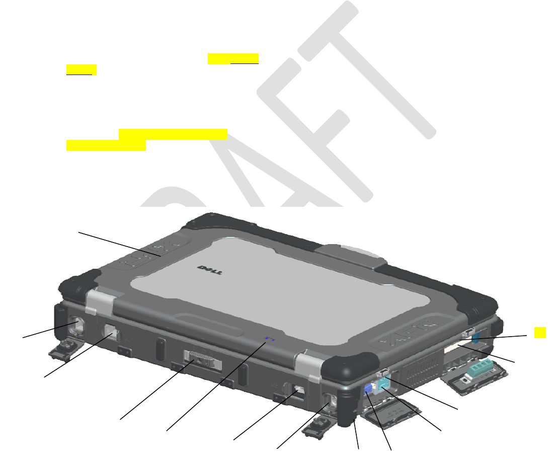
Back View
1 PR-481™ Ultra-Performance Chassis Material
2 RJ-11 modem connector
3 RJ-45 network connector 4 Battery access panel
2
3
4
6 7 8 9
10
11
12
5
1
13
Dell
™
Latitude™ E6400 XFR Setup and Features Information
Page 3
01/08/09
5 Battery/power lights 6 Multimode DisplayPort
7 AC adapter 8 Security cable slot
9 Video connector 10 eSATA/USB connector
11 USB PowerShare connector
12 Hard Disk Drive
13 Smart-card reader (see Smart Cards)
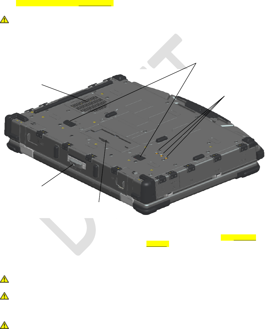
WARNING: Do not block, push objects into, or allow dust to accumulate in the air
vents. Do not store your Dell™ computer in a low-airflow environment, such as a
closed briefcase, while it is running. Restricting the airflow can damage the computer
or cause a fire. The computer turns on the fan when the computer gets hot. Fan noise
is normal and does not indicate a problem with the fan or the computer.
Bottom View
1 QuadCool™ thermal management 2 Battery access panel
3 Sliding cover to docking device connector 4 RF pass-through connectors (see RF Pass-
through)
5 Battery latch release
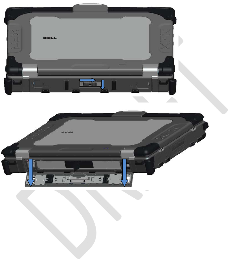
Battery Removal
CAUTION: Before you begin any of the procedures in this section, follow the safety
instructions that shipped with your computer.
CAUTION: Using an incompatible battery may increase the risk of fire or explosion.
Replace the battery only with a compatible battery purchased from Dell. The battery is
designed to work with your Dell computer. Do not use a battery from other computers
with your computer.
CAUTION: Before removing or replacing the battery, turn off the computer, disconnect
1
2
3
4
5
Dell™ Latitude™ E6400 XFR Setup and Features Information
Page 4 01/08/09
the AC adapter from the electrical outlet and the computer, disconnect the modem
from the wall connector and computer, and remove any other external cables from the
computer.
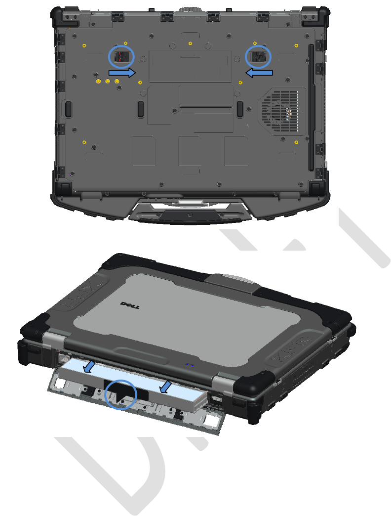
1. Release the rear panel.
a. Push the latch to the right, to its unlocked position.
b. Then, press the latch down.
2. Lower the rear panel.
3. Press in the two battery release latches on the bottom of the computer.
a
b
Dell
™
Latitude™ E6400 XFR Setup and Features Information
Page 5
01/08/09
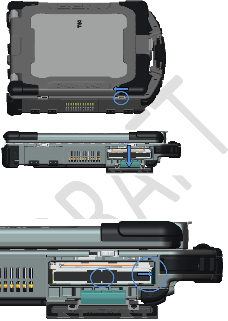
4. Use the tab on the edge of the battery to remove the battery from the computer.
Battery Installation
1. Insert battery until you hear a click and a mechanical stop.
2. Push the latch down and rotate the door into place.
3. Ensure the door is in the fully closed position, raise the latch up and then push the latch to the
left into the locked position.
Hard Disk Drive Removal
1. Open the hard disk drive door located on the left side panel by pushing the latch towards the
rear of the computer,
Dell
™
Latitude™ E6400 XFR Setup and Features Information
Page 6
01/08/09
and rotating the door down.
2. To remove the hard disk drive:
a. While pressing in the release tab on the right side of the hard disk drive compartment,
b. Use the tab on the edge of the hard disk drive to pull the hard disk drive from the
compartment.
Hard Drive Installation
1. Insert hard drive until you hear a click and a mechanical stop.
2. Rotate the door into place and press until it clicks into its closed position.
Operation of the PrimoSeal™ Doors
a
b
Dell™ Latitude™ E6400 XFR Setup and Features Information
Page 7 01/08/09
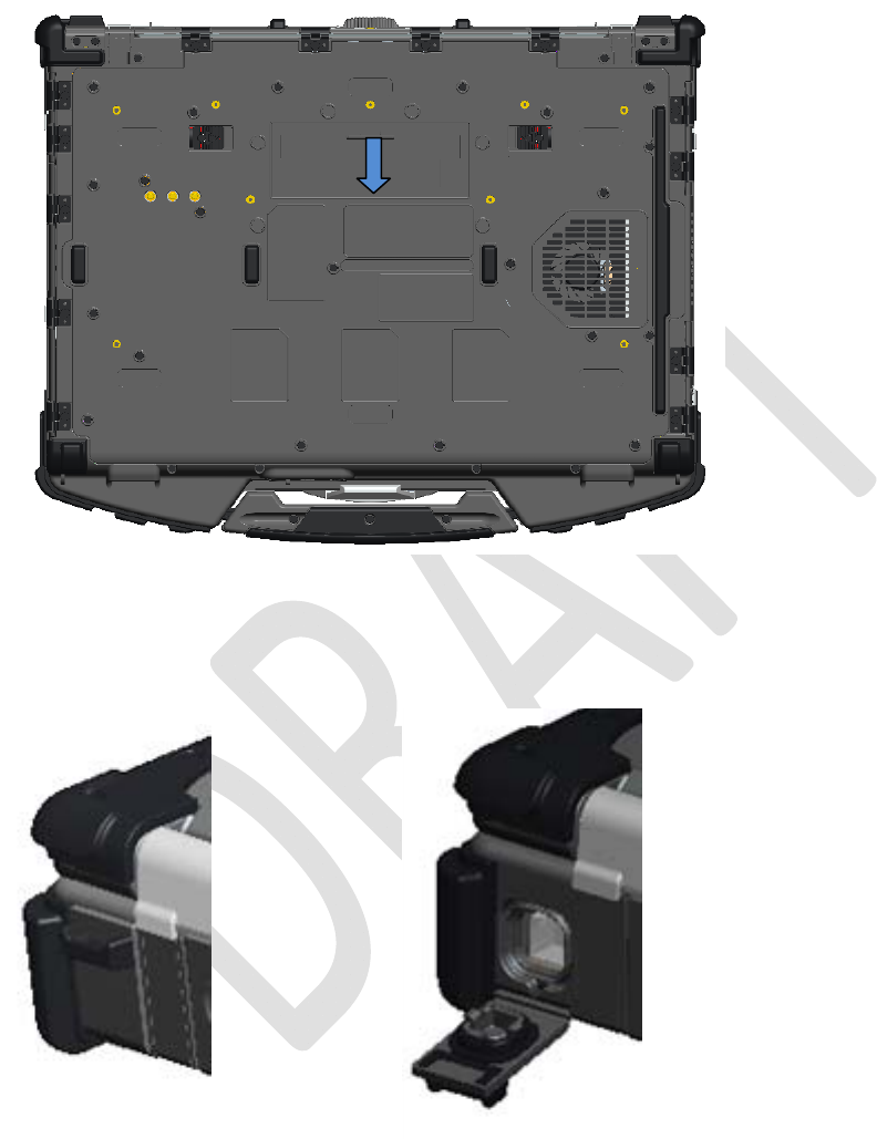
Docking Device Connector Door
The docking device connector door is opened by sliding the door towards the front of the computer
until it clicks into its open position. Reverse this procedure to close the door.
Press-Fit Door
The press-fit door is opened by inserting a finger into the door slot and pulling the door away from the
computer. To close the door, rotate it back into its closed position and press until it you hear it click
into position.
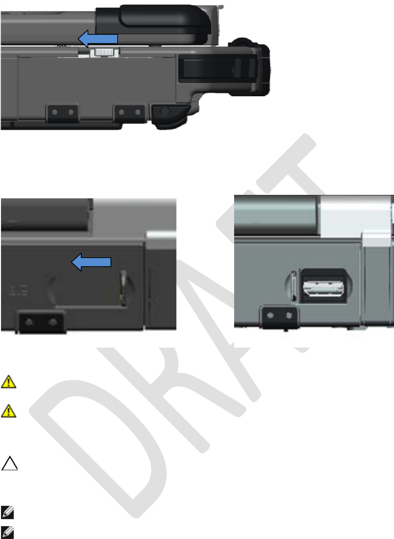
Latch Door
The latch door is opened by sliding the latch towards the rear of the computer, and then rotating the
door down. To close the door, rotate the door back into its closed position and press until you hear it
click into position.
Dell
™
Latitude™ E6400 XFR Setup and Features Information
Page 8
01/08/09
Slide Insert Door
The slide insert door is opened by sliding the door to its open position until it clicks into position.
Reverse the procedure to close the door.
Quick Setup
WARNING: Before you begin any of the procedures in this section, follow the safety
instructions that shipped with your computer.
WARNING: The AC adapter works with electrical outlets worldwide. However, power
connectors and power strips vary among countries. Using an incompatible cable or
improperly connecting the cable to the power strip or electrical outlet may cause fire
or equipment damage.
CAUTION: When you disconnect the AC adapter cable from the computer, grasp the connector,
not the cable itself, and pull firmly but gently to avoid damaging the cable. When you wrap the
AC adapter cable, ensure that you follow the angle of the connector on the AC adapter to avoid
damaging the cable.
NOTE: Some devices may not be included if you did not order them.
NOTE: It is recommended that you turn on and shut down your computer at least once before
you install any cards or connect the computer to a docking device or other external device, such
as a printer.
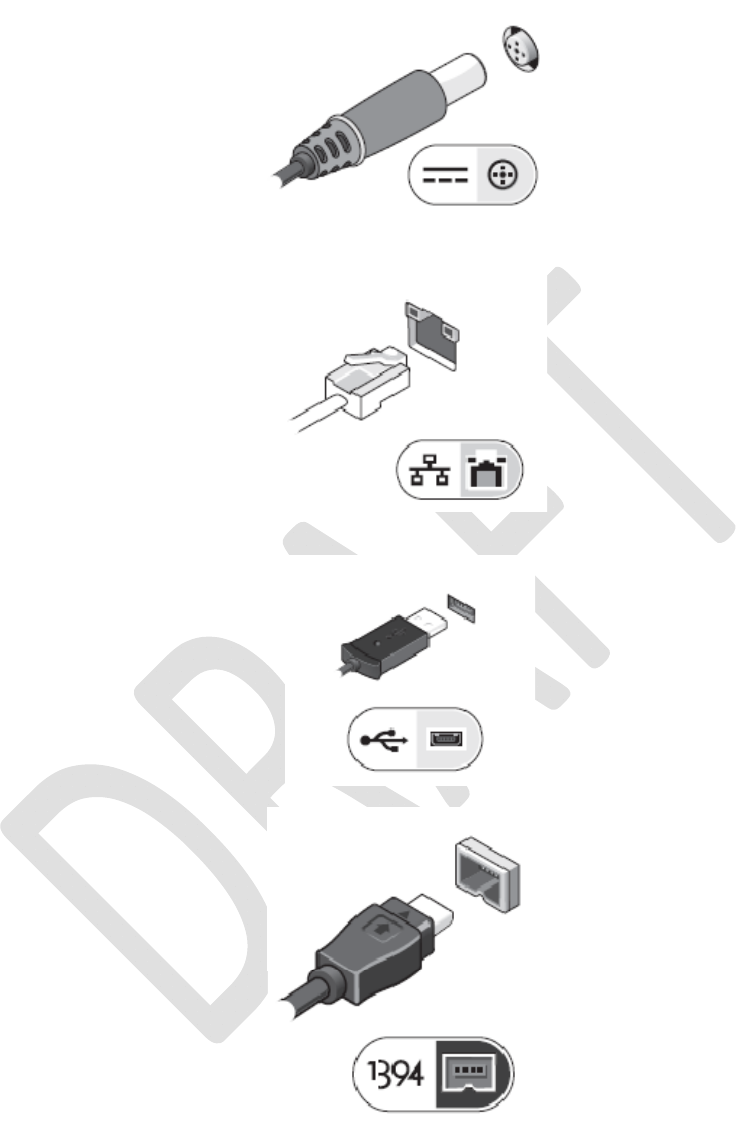
1. Connect the AC adapter to the AC adapter connector on the computer and to the electrical
outlet.
Dell™ Latitude™ E6400 XFR Setup and Features Information
Page 9 01/08/09
2. Connect the network cable.
3. Connect USB devices, such as a mouse or keyboard.
4. Connect IEEE 1394 devices, such as a DVD player.
5. Open the computer display and press the power button to turn on the computer.

Dell
™
Latitude™ E6400 XFR Setup and Features Information
Page 10
01/08/09
Smart Cards
Smart (CAC) cards are laptop credit-card shaped devices with internal integrated circuits. Using smart
cards can improve system security by combining something a user has (the smart card) with
something only the user should know (a PIN) to provide more secure user-authentication than
passwords alone.
There are two main types of Smart Cards:
• Contact Smart Cards — These cards have a contact area with many gold plated connection pads.
When inserted into a card reader, the information from the chip can be read and written.
• Contactless Smart Cards — These cards do not require any physical contact with the reader. The
chip communicates with the card reader through RFID induction technology. These cards require only
close proximity to an antenna of a card reader to complete transaction.
GPS
To be determined…
RF Pass-Through
In the event the XTG notebook has an integrated WiFi and/or Broadband radio, the RF signals can be
passed through a docking station to external TNC antenna connectors (LAN/WAN). This supports the
connection and use of external, vehicle-mounted antennas (purchased separately) for improved radio
performance.
DirectVue™ Touch Display Information
If you purchased your E6400 XFR Fully Rugged Notebook with the optional DirectVue Touch Display
please review the following user instructions and tips.
The E6400 XFR provides an optional touch screen display for entering and selecting data using an
approved pointing device such as your finger, a passive stylus or any non-abrasive smooth blunt
object that will not damage the touch display.
NOTICE: To ensure you properly care for and maintain your touch display, adhere to the care
instructions regarding the display.

Dell
™
Latitude™ E6400 XFR Setup and Features Information
Page 11
01/08/09
CAUTION: The optional DirectVue
TM
Touch Display has been designed to accept finger
touch as well as passive stylus input directly onto the screen. With the optional
DirectVue
TM
Touch Display, a stylus is included with the E6400 XFR for use in
selecting items on the touch screen. Other pointing devices can be used with the
touch screen such as any non-abrasive, smooth or blunt object that will not damage
the touch screen display. The touch screen surface can be damaged by ink pens,
marker pens or other pointed or abrasive objects. The use of non-approved input
devices that cause damage to the digitizer or LCD may not be covered by the limited
warranty.
The touch screen is pre-configured and pre-calibrated at the factory, but may require further
calibration to improve accuracy for entering or selecting data on the touch display. Please see the
3
Tools section for information on Calibrating your E6400 XFR Touch Display and using your stylus.
Accessing Drivers and Documentation
Your E6400 XFR DirectVue Touch Display’s drivers, touch-input parameters and documentation have
been pre-loaded at the factory. For experienced users or IT administrators - if you need to re-install
drivers, set up your E6400 XFR Touch Display or modify parameters please refer to the pre-loaded
E6400 XFR Touchkit Utility documentation for detailed instructions and refer to the summary provided
in
4
Touchkit Configuration Utility.
You can launch the pre-loaded documentation by selecting Start -> Programs -> Touchkit ->
Document.
Touchkit Configuration Utility
Your E6400 XFR DirectVue Touch Display system incorporates EETI technology. Touchkit is a software
utility tool that allows you to configure various touch features. You can launch Touchkit by clicking
Start -> Programs -> Touchkit -> Configure Utility.
NOTE: The touch screen is pre-configured and pre-calibrated at the factory, but may require
further calibration to improve accuracy for entering or selecting data on the touch display, or to
further configure it to your specific application.
Please refer to the pre-loaded documentation for the Touchkit Configuration Utility for a complete
description of all its capabilities and functionality.
You can launch the pre-loaded documentation for the Touchkit Configuration Utility by selecting
Start -> Programs -> Touchkit -> Document -> User Guide for Windows 2000/XP ->
Touchkit Utility.
The Touchkit software utility consists of tabs that allow you to determine the best settings for your
touch screen configuration.
• The
5
General tab shows all of the touchkit touch screen controllers installed in your system
• The
6
Tools tab provides access to calibration and touch position tools.
• The
7
Setting tab provides access to the configuration of beeps, clicks and mouse emulation as
well as selection of 9 point or 25 point calibration for linearization.
• The
8
Display tab provides the tools for mapping the touch screen area to specific areas of the
display. The default is full screen.
• The
9
Edge Parameters tab provides configuration for selecting items near the edge of the
touch screen.
• The
1
Hardware tab provides the model and firmware version of the Touchkit touch screen
controller.
• The
1
About tab provides the version of the Touchkit driver as well as providing a link for
downloading the latest driver.
Dell™ Latitude™ E6400 XFR Setup and Features Information
Page 12 01/08/09
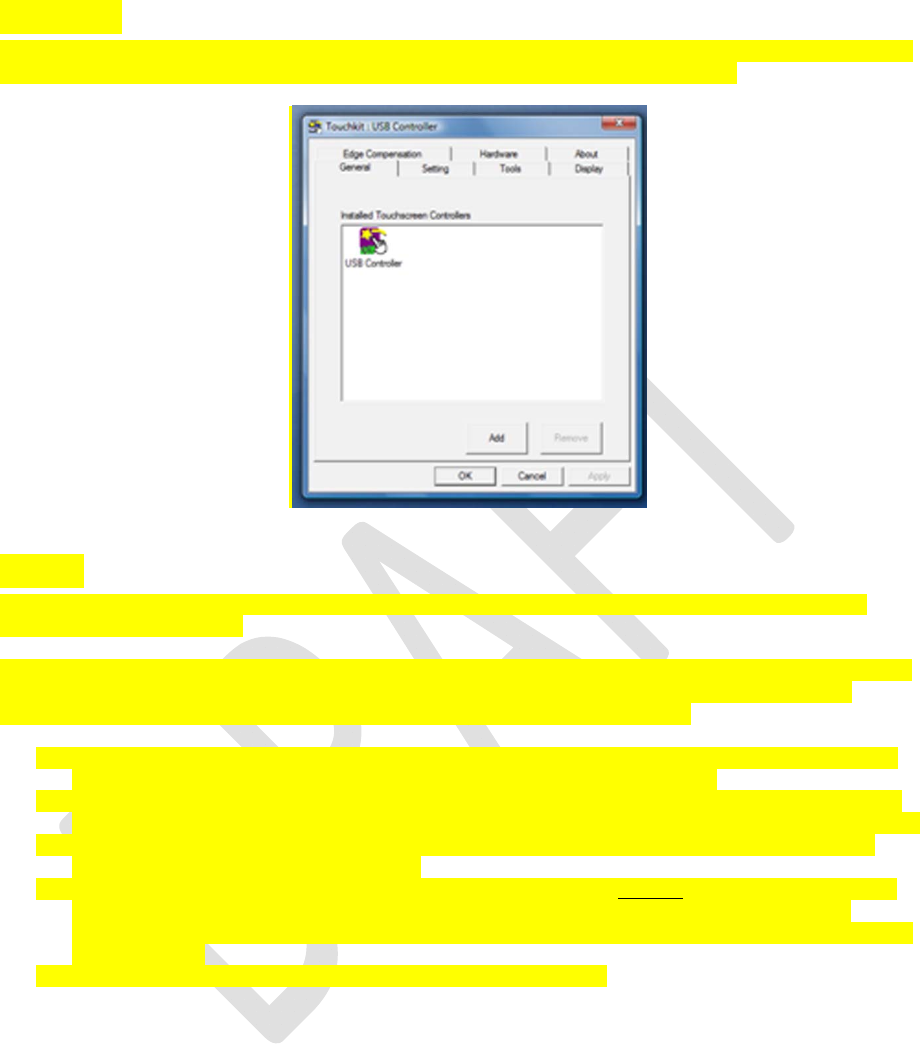
General
The general property page shows all the Touchkit touch screen controllers installed including RS232,
USB and PS2 interfaces. The E6400 XFR touch screen controller is a USB device.
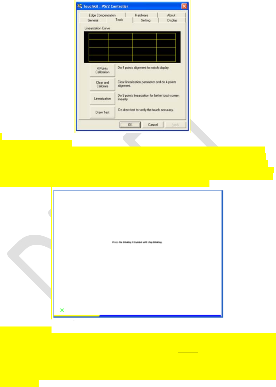
Tools
The Tools property page provides the following information and functions which are selected by
pressing the push buttons.
NOTE: Your touch screen is configured and calibrated at the factory. However, if you notice that the
calibration is not as precise as you would like, you can use the 4 Points Calibration and/or the
Linearization tool to provide a more accurate alignment of the touch screen.
• Graph of the Linearization Curve of the touch screen – for reference and troubleshooting
purposes. See its usage in the discussion of the Linearization function.
• 4 Points Calibration – Calibration aligns the touch panel with the video screen. The touch
screen must be calibrated to allow for positional accuracy of the stylus or finger touch inputs.
• Clear and Calibrate – Clears the calibration/linearization parameters and allows you to
perform the 4 points calibration again.
• Linearization (9 or 25 points linearization is set within the 1Setting tab) – the linearization
function provides for more precise mapping of the stylus or finger touch inputs. After
linearization is completed, the linearity of the touch screen will be shown in the Linearization
Curve window.
• Draw Test - used for accuracy and performance checking.
Dell™ Latitude™ E6400 XFR Setup and Features Information
Page 13 01/08/09
.
1. 4 Points Calibration
The touch screen must be calibrated before it can work accurately. This function pops up a new
window to guide you through the 4 points calibration. You should follow the guide to touch and
hold the blinking X symbol in the calibration window until it does not blink to make sure that the
utility can gather enough data for computation. In addition, a time line bar is shown in the bottom
of the window to indicate time elapsed. If the touch screen is not touched before the time line bar
reaches the right end, the calibration task will be terminated automatically.
2. Linearization
This function provides for more accurate touch screen positional alignment. The linearization
function pops up a new window to guide you through the 9 or 25 points calibration. Configuring
the function for 9 or 25 points calibration is accessed in the 1Setting tab. You should follow the
guide to touch and hold the blinking X symbol in the calibration window until it does not blink to
make sure that the utility can gather enough data for computation. In addition, a time line bar is
shown in the bottom of the window to indicate the time elapsed. If the touch screen is not touched
before the time line bar reaches the right end, the calibration task will be terminated
automatically.
Dell™ Latitude™ E6400 XFR Setup and Features Information
Page 14 01/08/09
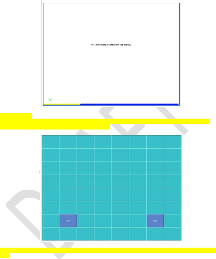
3. Draw Test
This function is used for accuracy and performance checking. You can use the stylus or finger
touch to draw or write across the displayed area.
You can press the Clear button to clear the window. Press the Quit button to terminate the draw
test.
Dell™ Latitude™ E6400 XFR Setup and Features Information
Page 15 01/08/09
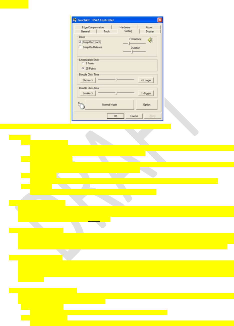
Setting
The Setting property page provides the following buttons and check boxes:
1. Beep
• Beep On Touch
Check this check box to enable driver to generate a beep sound when touch touchscreen
state is switched from untouched to touched state.
• Beep On Release
Check this check box to enable driver to generate a beep sound when touchecreen state
is switched from touched state to untouch state.
• Frequency
Adjust this frequency to control the beep sound frequency generated by the driver.
• Duration
Adjust this duration to control the beep sound duration.
2. Linearization Style
The Touchkit utility provides you with both 9 points and 25 points calibration for linearization.
You can select the suitable kind of linearization type with this setting. The Linearization
function is accessed under the 1Tools tab.
3. Double Click Time
The double Click Time group is used to set system double click time. Changing this value will
affect the double click behavior for all of the mice devices in the system. Two continuous clicks
at the same area within this specified time period will be recognized as a double click event.
4. Double Click Area
The double click area group is used to set the system double click area. Changing this value
will affect the double click behavior for all of the mice devices in the system. Two continuous
clicks within the specified area in the specified double click time will be recognized as a double
click event.
5. Mouse Emulation mode
There are 5 mouse emulation modes for the Touchkit touch screen controllers. Press on the
button to change the emulation mode.
• Normal Mode
You can select this mode to select objects, and drag objects.
• Click On Touch
With this Click On Touch mode, the driver emulates a mouse click event when the touch
Dell™ Latitude™ E6400 XFR Setup and Features Information
Page 16 01/08/09
screen state is switched from un-touched state to touched state. Then, the driver always
generates a mouse move event and tracks the touch position until the touch screen state
switches to the un-touch state.
• Click On Release
With this Click On Release mode, the driver emulates a mouse click event when the touch
screen state is switched from touched state to un-touched state.
• Click On Touch without moving cursor
With this mode, the driver behaves similarly to the Click On Touch mode. The cursor does
not move to the touch position except for the first touch point.
• Click On Release without moving cursor
With this mode, the driver behaves similarly to the Click On Release mode. The cursor
does not move to the touch position except for the lift-off point.
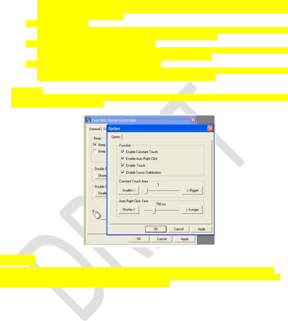
6. Option
You can access advanced configuration functions with the Option button. Press the button, and
the following window will appear.
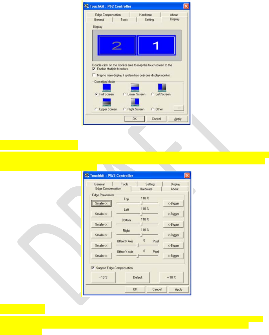
Display
The Touchkit driver supports multiple monitor and display systems. To work with multiple monitor
systems, you need to perform the proper configuration to map the touch screen working area to the
correct system display area using the Display property page.
Dell™ Latitude™ E6400 XFR Setup and Features Information
Page 17 01/08/09
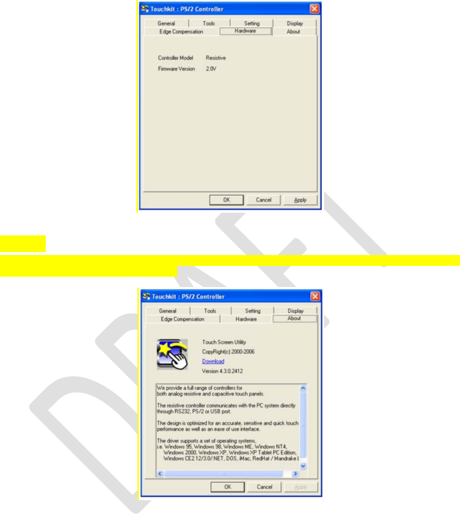
Edge Parameters
For some special touch screen applications where the edge area of the full screen cannot be reached,
Touchkit provides you with this edge compensation tool to solve the problem and allow for touching
the edge area without accuracy loss.
Hardware
The Hardware property page shows the model and firmware version of the Touchkit controller. The
software will query the hardware information from the controller and show the information as
illustrated here.
Dell™ Latitude™ E6400 XFR Setup and Features Information
Page 18 01/08/09
About
The About property page shows information regarding the Touchkit driver, including providing a link to
allow you to download the latest driver.

Dell
™
Latitude™ E6400 XFR Setup and Features Information
Page 19
01/08/09
Specifications
NOTE: Offerings may vary by region. For more information regarding the configuration
of your computer, click Start -> Help and Support and select the option to view
information about your computer.
Video
NOTE: Your Dell™ computer has both integrated and discrete video options.
Video type Integrated and discrete on system board, hardware accelerated
Data bus Integrated video or PCI-Express video x16
Video controller Integrated video: Intel
®
Graphics Media Accelerator 4500 MHD
Discrete video: nVIDIA Quadro NVS 160M
Video memory:
Integrated video:
Up to 1 GB (with 2 GB or more system memory – Microsoft
®
Windows
®
XP)
Up to 1.7 GB (with 4GB or more system memory – Windows Vista
®
)
Discrete video: 256 MB dedicated memory
Battery
Type 12-cell “smart” lithium ion prismatic rugged slice (84 Whr)
6-cell “smart” lithium ion (56 Whr)
4-cell “smart” lithium ion (35 Whr)
Dimensions:
4-cell and 6-cell lithium-ion batteries:
Depth 206 mm (8.11 inches)
Height 19.8 mm (0.78 inches)
12-cell lithium-ion rugged slice battery:
Depth 14.48 mm (0.57 inches)
Height 217.24 mm (8.55 inches)
Weight:
4-cell primary battery 0.24 kg (0.53 lb)
6-cell primary battery 0.33 kg (0.73 lb)
12-cell slice battery 0.85 kg (1.87 lb)
Voltage
4-cell battery 14.8 VDC
6-cell battery 11.1 VDC
12-cell rugged slice battery 14.8 VDC
Temperature range:
Operating -29
0
to 60
0
C (-20
0
to 140
0
F)
Storage -51
0
to 71
0
C (-60
0
to 160
0
F)

Dell™ Latitude™ E6400 XFR Setup and Features Information
Page 20 01/08/09
Coin-cell battery CR-2032
AC Adapter
Input voltage 100-240 VAC
Input current (maximum) 1.5 A
Input frequency 50-60 Hz
Temperature range:
Operating 00 to 350C (320 to 950F)
Storage -400 to 650 (-400 to 1490F)
PA-12 65 W Travel AC adapter:
Output voltage 19.5 V DC
Output current 3.34 A
Height 15 mm (0.6 inches)
Width 66 mm (2.6 inches)
Depth 127 mm (5.0 inches)
Weight 0.29 kg (0.64 lb)
PA-10 90 W D-Series AC adapter:
Output voltage 19.5 V DC
Output current 4.62 A
Height 32 mm (1.3 inches)
Width 60 mm (2.4 inches)
Depth 140 mm (5.5 inches)
Weight 0.425 kg (0.9 lb)
PA-3E 90 E-Series AC adapter:
Output voltage 19.5 V DC
Output current 4.62 A
Height 15 mm (0.6 inches)
Width 70 mm (2.8 inches)
Length 147 mm (5.8 inches)
Weight 0.345 kg (0.76 lb)

Dell™ Latitude™ E6400 XFR Setup and Features Information
Page 21 01/08/09
Information in this document is subject to change without notice.
© 2008 Dell Inc. All rights reserved. Printed in the U.S.A.
Reproduction in any manner whatsoever without the written permission of Dell Inc. is strictly forbidden.
Trademarks used in this text: Dell, Latitude, Wi-Fi Catcher, and the DELL logo are trademarks of Dell Inc.; Augmentix and
QuadCool are registered trademarks,, and PR-481, and DirectVue are trademarks of Augmentix Corporation; Intel is a
registered trademark of Intel Corporation in the U.S. and other countries; Microsoft, Windows, and Windows Vista are
either trademarks or registered trademarks of Microsoft Corporation in the United States and/or other countries.
Other trademarks and trade names may be used in this document to refer to either the entities claiming the marks and
names or their products. Dell Inc. disclaims any proprietary interest in trademarks and trade names other than its own.
Model P02G