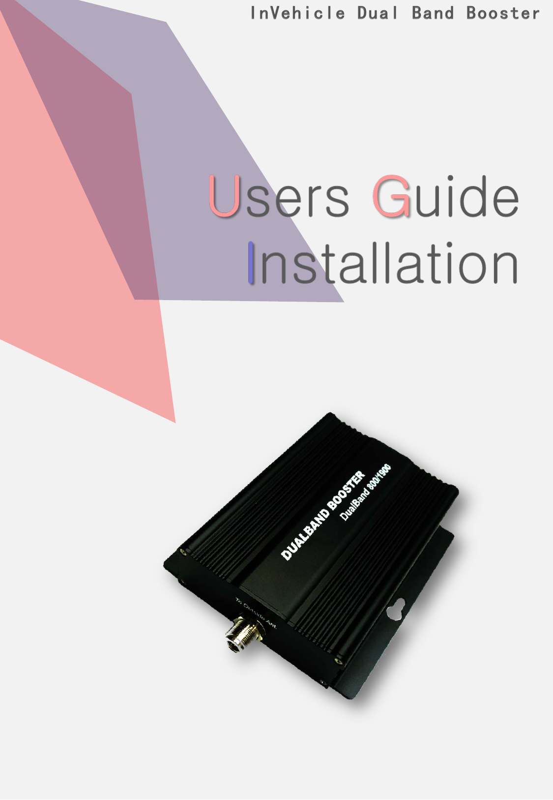
OPISYS orporated AVHR-5000N InVehicle Dual Band Booster User Manual Manual rev 2

OPISYS Incorporated InVehicle Dual Band Booster Manual rev 2

Manual - rev 2

2 All rights reserved AVHR-5000N - Content - 1. Precautions 2. System Components 2.1 Components 2.2 Installation 3. General Information 3.1 Features 4. Installation 4.1 External Antenna Installation 4.2 Inside Antenna Installation 4.3 Amplifier and Antenna Connection 4.4 Operating Instructions 5.   Trouble Shooting 5.1 LED Alarm 5.2 Insufficient  Outside Signal Problem 5.3 Vehicle Battery Discharge Problem 6.   Safeguard features 6.1 Summary 6.2 Features 7. Specification           7.1 Amplifier Specification 7.2 Outside Antenna Specification 7.3 Inside Antenna Specification 7.4 Cigarette Power Code Specification 8. Certificates 9. Manufacturers 10. Memo
3 All rights reserved AVHR-5000N 1. Precautions                                           1.1  Do not drop the device                 - It may damage the product and its function       1.2  Do not place near magnetic materials                - It may cause of possible malfunction       1.3  Product is recommended to be used with the cigarette power cord.               For any alternative cable use, please ask professional installers.                 - There is a high risk of frying up the device if inaccurately powered.       1.4  Please unplug both Cigarette Power Supply and Fuse Cable during               non-operation to avoid any possible battery discharge.       1.5  Install the product where it is recommended                - It may not properly operate on unadvised location       1.6  Do not repair or remodel                - It may cause malfunction. Please contact your store representative                             if there is a problem Reference :    Direction/Information for the proper operation Caution :    Information for users to avoid malfunctions Warning :      Instructions for users to avoid unexpected hazard    This is a CONSUMER device. BEFORE USE, you MUST REGISTER THIS DEVICE with your wireless provider and have your provider’s consent. Most wireless providers consent to the use of signal boosters. Some providers may not consent to the use of this device on their network. If you are unsure, contact your provider. You MUST operate this device with approved antennas and cables as  specified by the manufacturer. Antennas MUST be installed at least 20cm (8 inches) from any person. You MUST cease operating this device immediately if requested by the FCC or a licensed wireless service provider. WARNING. E911 location information may not be provided or may be inaccurate for calls served by using this device. This is a CONSUMER device.
4 All rights reserved AVHR-5000N                 1.7  Do not install device while driving                 - Please avoid any activities that may cause careless driving             1.8   Turn off the ignition before set up the device.         1.9   Do not install the device near any air bags in a car                - It may cause severe damage if air bags explode.                            1.10  Do not touch the device with wet hands                - It may cause possible risk of an electric shock       1.11  Keep the installation location of inside and outside antenna clean                - Please organize cable lines and antenna locations to avoid any                     possible interference while operating a vehicle.       1.12  Stop and Turn Off the device immediately if a smog comes out of                 the product or any strange odor is detected from the product                - Do not attempt to fix the device. Please contact your store                                      representative               1.13  Warning message for use of unauthorized antennas, cables,                and/or coupling devices              - It may not properly operate
5 All rights reserved AVHR-5000N ① . Inside Antenna: connects signal between mobile phone and amplifier ②.  Dual Band Amplifier: amplifies signal by receiving base station signals       through Outdoor antenna to In-door Antenna ③.  User Manual: shows how to operate system  ④.  Cigarette Power Adapter: Power Source ⑤.  Outside Antenna: connects signal between base station and amplifier ⑥.  List of approved antennas   ⑦.  List the default antenna, cable, and/or coupling device that are shipped       with the booster  2. System Components            2.1  Components  Note: (A)  Mark  Purchase separately ⑤ Outside Antenna ① Inside Antenna ② Dual Band Amplifier ③ User Manual ④  Cigarette power adapter  (A)  (A) Inside Antenna TQC-900/1800E TS210380 Outside Antenna TQC-900/1800CII TS210580 Base Station ① ② ⑤ ④            2.2  Installation
6 All rights reserved AVHR-5000N      3.1.1 Summary      The device may be installed on cars, trucks, trailers, boats and homes to        improve user’s  mobile phone signal.                     (Please see page 13 for Operating Frequency)      3.1.2  Features                                    I. Decrease dropped call II. Increase 2G/3G data speed III. Battery life extension IV. Voice quality improvement      I. Strong coverage area         -  Gain 48dB  II. Automatic Overload Protection & Detection System         -  Plug and Operate Systems III. 23dBm(0.2W)  Output power         - Provides High Data Communication rate  IV.  Complete Repeater Kit.         - All components included for installation  V. Dual Band Frequency Broadband          - 800MHz / 1900MHz  VI. LED Alarm System  VII. GUI(Graphic User Interface)         - Please ask professional installers about GUI program. VIII.  Cost Effective Application for Vehicles, Boats, and Homes         - For any Home & Boats applications, optional antennas           (inside & out) and connectors may be required.      3. General Information            3.1  Features
7 All rights reserved AVHR-5000N 4. Installation 4.1  External Antenna Installation         4.1.1 Outside antenna has magnetic feature to mount on the roof of vehicle         4.1.2 Outside antenna distance should be at least 5 feet from inside antenna          4.1.3 Recommended to mount outside antenna near rear end of the roof.            Good Better Best 4.2  Inside Antenna Installation          4.2.1Inside antenna is mounted using the self-adhesive. It must be placed in a location        that will be at least 0.5m (20 inches) from where cell phones will be located.         4.2.2 Before installation, please remove attached paper         4.2.3 Recommended to mount indoor antenna near suggested area as below
8 All rights reserved AVHR-5000N 4.3  Amplifier and Antenna Connection         4.3.1 Place the amplifier under the seat or appropriate location.  4.3.2 Connect inside and outside antenna connector to Amplifier. 4.4  Operating Instructions         4.4.1 Plug in cigarette power cord and press the button to turn ON as shown                  below. The red LED light should be ON indicating its operation.
9 All rights reserved AVHR-5000N         4.4.2 Connect DC Jack as shown below         4.4.3 Turn ON the Switch as shown below         4.4.4 After turning ON the switch, green LED light will be on.                   Green LED indicates  that system is in a normal mode.                   Green and Red LED will flash 3 times simultaneously.                    After the initial loading, the green LED light will be on during operation.
10 All rights reserved AVHR-5000N 5. Trouble Shooting 5.1  LED Alarm ITEM GREEN LED RED LED Problem Reference Setting/Resetting ON  (after 3 times blinks) 3 times blinks See 4.1.1 Normal Mode ON OFF See 4.1.2 Cellular Overload Blink( once)  -  See 4.1.3 Oscillation Blink(twice)  -  See 4.1.4 Insufficient Isolation Blink(3 times)  -  See 4.1.5 Alarm Checking Blink(Consecutively)  -  See 4.1.6 Sleep Mode Blink(4 times)  -  See 4.1.7 PCS Overload  -  Blink( once) See 4.1.3 Oscillation  -  Blink(twice) See 4.1.4 Insufficient Isolation -  Blink(3 times) See 4.1.5 Alarm Checking  -  Blink(Consecutively) See 4.1.6 Sleep Mode  -  Blink(4 times) See 4.1.7         5.1.1  ①  Check if the LED light  is ON, on the cigarette power adapter                   ②  Verify that DC cord is connected correctly                                          5.1.2 ② Green LED light is normal mode. If it blinks 2-4 times in a few                       seconds, please see 4.1.3 ~ 4.1.7                     5.1.3 ② This is normal mode that checking on input power signal and  shows                        signal status to users.       ②  It will go resume  normal operation mode after Overload Detection.          5.1.4 ②  There is an oscillation between inside and outside antenna.                  ②  This status is caused by surrounding structural interferences that               can temporarily disturb mobile signals. The amplifier will auto detect                         available signals as you drive to other locations.                         The Green LED light will turn ON once normal mode resumes.           5.1.5 ②  The isolation may occur between inside and outside antenna                  ②  If LED light blinks three times during installation, move the inside and                            outside antenna away from each other and RESTART the amplifier.                   ②  If LED light blinks three times after the installation, it could be caused                       by surrounding structure.                        The device will auto adjust as vehicle moves.
11 All rights reserved AVHR-5000N 5.2  Insufficient Outside Signal Problem        Even after installation, if there is no base stations around your       vehicle (Ex. No Service Enabled Zone), you may not receive any cellular       signals.                   5.1.6 ① The Overload Protection System includes the following:                AGC (Automatic Gain Level Control)                           AIC   (Automatic Isolation Detection)                           ASC (Automatic Reset Control)                  ② During Alarm checking process, the Amplifier may not operate.                  5.1.7 ② When LED is green or red with a flash four times at working,                                Sleep Mode is operated. Because reverse signal has not been existed                               for a certain time.                          ② If Reverse signal occur at the Sleep Mode, repeater is working normally                               and LED does not flash.                                                  5.3  Vehicle Battery Discharge Problem            Verify cigarette power adapter has LED light ON as shown below. If not, check             either vehicle key is appropriately positioned or engine is ON. In case of             battery discharge, replace the battery.
12 All rights reserved AVHR-5000N I. Isolation  check mechanism II. Oscillation check mechanism III. Sleep Mode mechanism IV. ALC(Auto Level Control) mechanism V. RF Shut Down mechanism 6. Safeguard features 6.1  Summary    This equipment have functions to protect as follows. 6.2  Feature          6.2.1   Isolation check mechanism                 - The booster automatically checks the isolation by increasing the                    DL path gain by 1dB when the power supply is switched on and/or                     the oscillation occurs.                   It works normally  when the isolation is over the maximum gain(48dB)                   plus 10dB, 58dB.           6.2.2   Oscillation check mechanism                 - Anti-oscillation function is to protect Booster by D/L path off                    when oscillation in service. D/L shutdown by isolation check function                   when D/L path output power exceed oscillation limit value.                      6.2.3   Sleep Mode mechanism                 - When there is no U/L path Input signal, Booster shall be shut down                    after 30 seconds.                   Under the Sleep Mode condition, if U/L path input signal is above                    -92dBm, U/L path shall be turned on.          6.2.4   ALC(Auto Level Control) mechanism                 - ALC function is always working to protect Booster.           6.2.5   RF Shut Down mechanism                 - AMP is automatically shut down when the system output power                    exceeds the set point over five seconds.
13 All rights reserved AVHR-5000N 7. Specification 7.1  Amplifier Specification  Items Cellular PCS Remarks Operating Frequency Downlink 869 ~ 894 MHz 1930 ~ 1990 MHz Uplink 824 ~ 849 MHz 1850 ~ 1910 MHz Gain Downlink 48dB±2.0dB 48dB±2.0dB Uplink 48dB±2.0dB 48dB±2.0dB Output Power Level Downlink +5dBm +5dBm @ 1FA Uplink +23dBm +23dBm Ripple Downlink < 5dB < 5dB Uplink < 5dB < 5dB Noise Figure Downlink < 5dB < 5dB Frequency Center  Uplink < 5dB < 5dB Frequency Center  ALC Level Downlink +5dBm ±1dB +5dBm ±1dB @ 1FA Uplink +23dBm ±1dB +23dBm ±1dB Shutdown Level Downlink +6dBm ±1dB +6dBm ±1dB After ALC Uplink +24dBm ±1dB +24dBm ±1dB Modulation Type GSM. EDGE, CDMA, EVDO, WCDMA, LTE Input Voltage 6.0Vdc / 3.5A Cigar Charger ‘s Vdc Power Consumption 6.0Vdc / 1050mA @ No call RF Connector Type FME-male  Operating Temperature -40°C ~ +50°C (-40°F ~ 122°F) Size(L*W*H) 5.5”*4.8”* 1.3”    (140.5 * 123 * 34 mm) ● Additional Information:      The EUT is a bi-directional amplifier for the boosting of cellular phone signals      and data communication devices.      The following frequency bands and emission types are utilized. Frequency Band Uplink 824~849 1850~1910 Downlink 869~894 1930~1990 Emission Designators CDMA  HSPA  LTE  EVDO  EDGE GSM F9W F9W G7D F9W G7W GXW ● EUT Operation during Tests      The EUT was in a normal operating condition.
14 All rights reserved AVHR-5000N 7.2  Outside Antenna Specification  Items Frequency Range Remarks Operating Frequency 890 ~ 960 MHz 1710 ~ 1990 MHz - Gain 5dBi  - VSWR ≤ 2.0 : 1  - Impedance 50 Ω  - Max Power-W  50W Polarization Vertical  - Connector FME(Female)  - Antenna  Length 11.02 inch (28Cm)  - Items Frequency Range Remarks Operating Frequency 700 ~ 800 MHz 824 ~ 894 MHz 880 ~ 960 MHz 1710 ~ 1880 MHz 1850 ~ 1990 MHz 2110 ~ 2170 MHz - Gain 5dBi  - VSWR ≤ 2.0 : 1  - Impedance 50 Ω  - Max Power-W  50W Polarization Vertical  - Connector FME(Female)  - Antenna  Length 12.25 inch (31Cm)  - ● TQC-900/1800CII  ● TS210580
15 All rights reserved AVHR-5000N 7.3  Inside  Antenna Specification  Items Frequency Range Remarks Operating Frequency 820 ~ 890 MHz 1710 ~ 1990 MHz - Gain 2dBi  - VSWR   < 2.1 : 1  - Impedance 50 Ω  - Max Power-W  25W Polarization Vertical or Horizontal  - Connector FME(Female)  - Antenna Length 4.73 inch (12cm)  - Items Frequency Range Remarks Operating Frequency 700 ~ 800 / 824~ 894 MHz 880~960 / 1850 ~ 1990 MHz - Gain 3dBi  - VSWR   < 1.8 : 1  - Impedance 50 Ω  - Max Power-W  25W Polarization 360º  - Connector FME(Female)  - Antenna  Length 3.4 inch (8cm)  - ● TQC-900/1800E  ● TS210380
16 All rights reserved AVHR-5000N         7.4.2  Output  Specification Items Min Typical Max Normal DC  Output  Voltage  -  6.0Vdc  - DC  Output  Voltage  Range 5.7Vdc  -  6.3Vdc Load Current  Range  -  -  3.5A Ripple  -  -  350mV Over Current Protection 4.2  -  7.0A Short Circuit  Protection  -  Yes  -  7.4  Cigarette Power Code Specification      7.4.1 Input Specification Items Min Typical Max Normal DC  Input  Voltage 12V  -  24V DC  Input  Voltage  Range 12V  -  24V DC  Input  Voltage  Current  -  -  3.0A 8. Certificates        8.1  FCC Certification              Model : AVHR-5000N                   ▪ Certificate Data : April 18, 2014                   ▪ Certificate Number: Q4EAVHR-5000N 9. Manufacturers        9.1  Location                          ▪ Address : 590 West Central Ave Unit E, Brea CA 92821               ▪ Tel : 714-990-6244               ▪ Fax : 714-990-6243
17 All rights reserved AVHR-5000N Memo

Navigation menu