OPISYS orporated USHR-700L In-Building Repeater System User Manual Revised
OPISYS Incorporated In-Building Repeater System Users Manual Revised
UserManual.wiki
>
OPISYS orporated
>
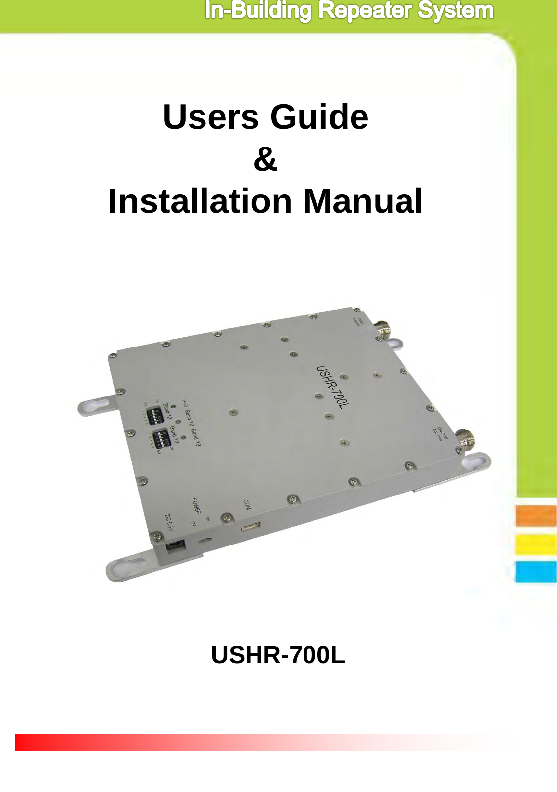
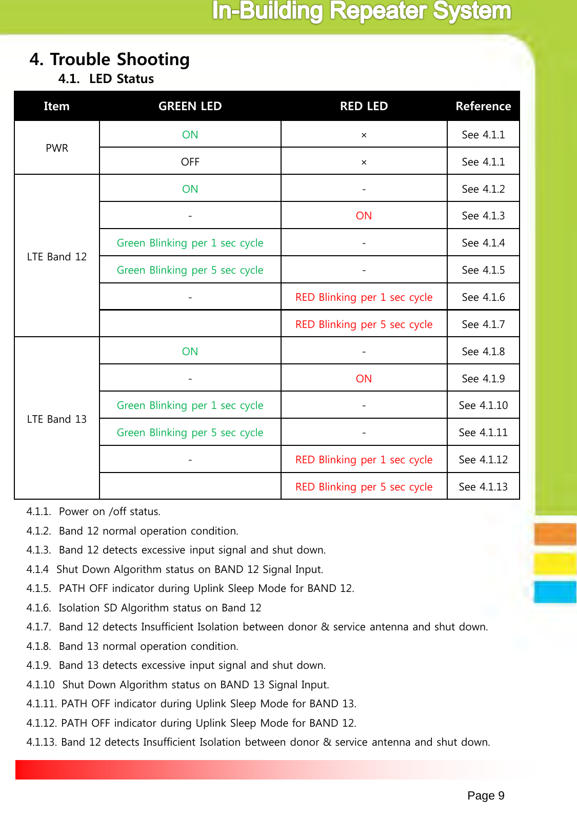
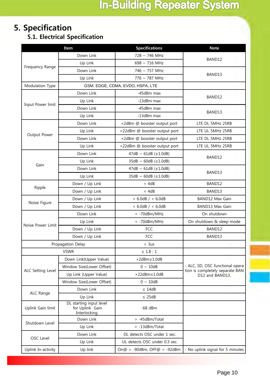
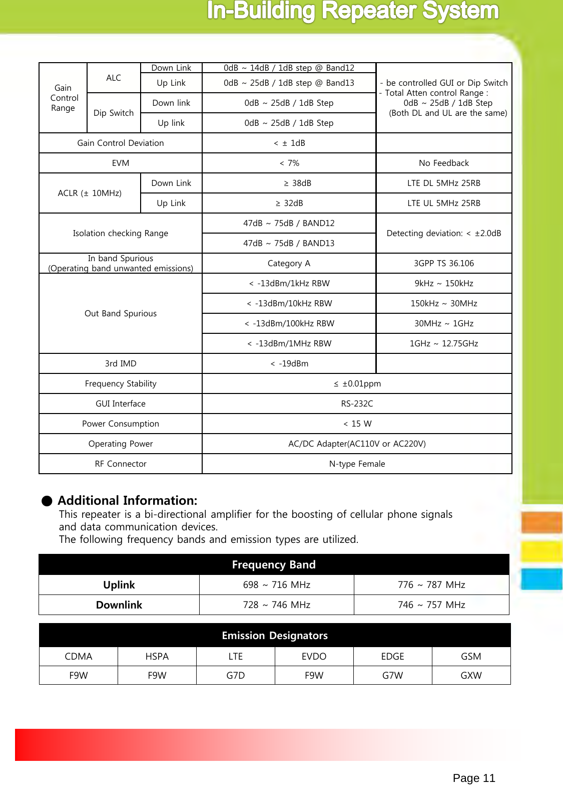
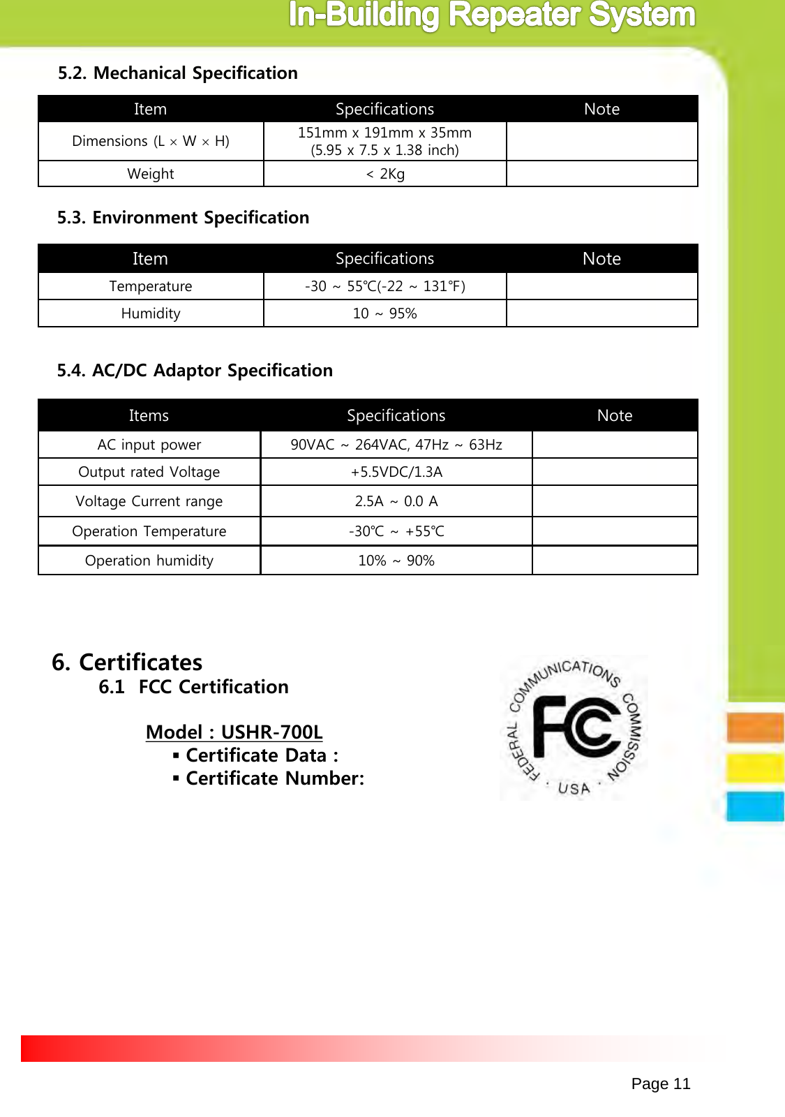
USHR 700L User Manual
Users Manual Revised
Navigation menu
Upload a User Manual
Namespaces
Wiki Guide
HTML
PDF
Info
Views
User Manual
Discussion / Help
Navigation