OPISYS orporated USHR-700L In-Building Repeater System User Manual Revised
OPISYS Incorporated In-Building Repeater System Users Manual Revised
Users Manual Revised

Users Guide
&
Installation Manual
USHR-700L
Page 2
- Content -
1. General Information
2. System Components
3. Installation
4. Trouble Shooting
5. Specification
6. Certificates
7. Memo
This is a CONSUMER device.
BEFORE USE, you MUST REGISTER THIS DEVICE with your wireless
provider and have your provider’s consent. Most wireless providers consent to
the use of signal boosters. Some providers may not consent to the use of this
device on their network. If you are unsure, contact your provider.
You MUST operate this device with approved antennas and cables as specified
by the manufacturer. Antennas MUST be installed at least 20 cm (8 inches)
from any person.
You MUST cease operating this device immediately if requested by the FCC or
a licensed wireless service provider.
WARNING. E911 location information may not be provided or may be
inaccurate for calls served by using this device.
Page 3
1. General Information
1.1. Precautions
1.1.1 Do not drop the device
- It may damage the product and its function
1.1.2 Do not place near magnetic material
- It may cause of possible malfunction
1.1.3 Product is recommended to be used with original AC/DC adapter
1.1.4 Install the product where it is recommended
- It may not properly operate if it is not recommended location
1.1.5 Do not disassemble/ repair the product
- Warranty may void once you disassemble the product.
1.1.6 Turn off the device immediately if a smog or any strange odor is
detected from the product.
1.1.7 Use contained bolt to install on the wall. Make sure it is safely
installed before operation
Reference : Direction/Information for the proper operation
Cautions : Information for users to avoid malfunctions
Warning : Instruction for users to avoid unexpected hazard
1.2 . Features
1.2.1. Summary
This device may be installed on residential area, office, warehouse etc. .
Following is advantage of using in-building repeater system.
This is RF type amplifier for 700 MHz LTE of Band 12 and Band 13 signal
enhancement.
(Please see page 13 for Operating Frequency in details)
1.2.2 . Features
Page 4
I. Decrease dropped call rate
II. Increase signal strength
III. Improve Data / Voice quality
IV. Prolong hand phone battery life
V. Improve data Communication Rate
I. Wider Coverage area
- Band 12 Gain DL 61dB /UL 60dB, Band 13 Gain DL 61dB/ UL 60dB.
II. ALC(Automatic output Level Control)
- Stabilize operation in any radio environment
III. Fulfill 3GPP spurious specification at +22dBm output power
(category A)
- Provide high Data Communication Rate
IV. Easy gain control by dip switch located on the front side of product
V. Support dual band
- enable to connect service from multiple currier simultaneously
- LTE Band 12/13 service simultaneously
- LTE Band 12/13 adopt independent operation algorithm
VI. Check status of product by LED indicator
VII. Manage and control product by GUI(Graphic User Interface)
- Please ask professional installer about GUI Program
VIII. Enable to stay connected in homes and offices
- Please ask professional installer for installation on homes & offices
IX. LTE ready
X. Automatically isolation detection and gain setting
- Power ON/OFF when oscillation occurs.
XI. UP Link Sleep Mode
- If no signal detected for 5 minutes, UP Link Path Shuts Off
XII. UL/DL gain Interlocking Mode
1.2.3. Function
Page 4
I. S/D ( Auto Shut Down Mode)
Built-In Automatic Self-Monitoring Features for Anti-Oscillation:
Automatic Shut Down Mode operates when oscillation in the uplink and downlinks bands
are detected, thus terminates potential harmful interference to wireless networks.
• 1 MINUTE Non-Operative Mode on the first initial oscillation detection.
• Default Algorithm Re-Set Mode when Auto S/D Mode is cleared
• Complete Shut Off Mode on the 5th repetition of Auto S/D Mode status.
BAND 12 & BAND 13 PATH are independently monitored and operated.
II. Intermodulation Gain & Power Limit Control
Uplink & Downlink PATH formulate consistent link balance to regulate its
input and output gain & power limits.
max UL gain < - 34dB – RSSI + MSCL (“ FCC 13-21,(i), 78p”)
RSSI : the downlink composite received signal power at the donor port
( calculation value : DL Output – DL Gain )
MSCL : Mobile Station and repeater service port minimum Coupling Loss
( setting value )
BAND 12 & BAND 13 PATH gain limits are independently controlled
III. ALC (Automatic Level Control)
ALC is implemented due to the higher rate of signal changes and wide dynamic range in
LTE Bands, the Automatic Gain Power Control (AGC) may experience off set time
synchronization error.
•Optimal Window Size (frequency range) sets the optimal level to increase
faster response to LTE Frequency changes on the basis of gain power
control via signal input/output differential calculation
BAND 12 & BAND 13 PATH gain limits are independently controlled
IV. UL PATH Automatic Sleep Mode
If coverage is non-existent (Zero Area Zone), Uplink PATH shuts off as
A
Harmful Interference Avoidance
protocol and minimizes its power
consumption.

1.2.3. Function
Page 4
IV. UL PATH Automatic Sleep Mode (continue )
• Automatic Turn OFF / if UL PATH < -92dBm
• Automatic Turn ON / if UL PATH > -90dBm
**BAND 12 & BAND 13 PATH gain limits are independently controlled
V. Oscillation Auto Prevention
•Degradation Protection: Detects potential performance degradation due to
the overload LTE feedback (over-heating) signals by Isolation Check & Gain
Configuration.
•Feedback Limits: Sets the operating range to exceeding high level Signals
from Donor Antenna (external antenna) of a signal booster to Service
Antenna (internal antenna)
BDA Gain < Antenna to Antenna Isolation – 15dB
If optimal isolation gain is not attained, PATH OFF shuts off automatically
**BAND 12 & BAND 13 Uplink PATH are independently controlled
Page 5
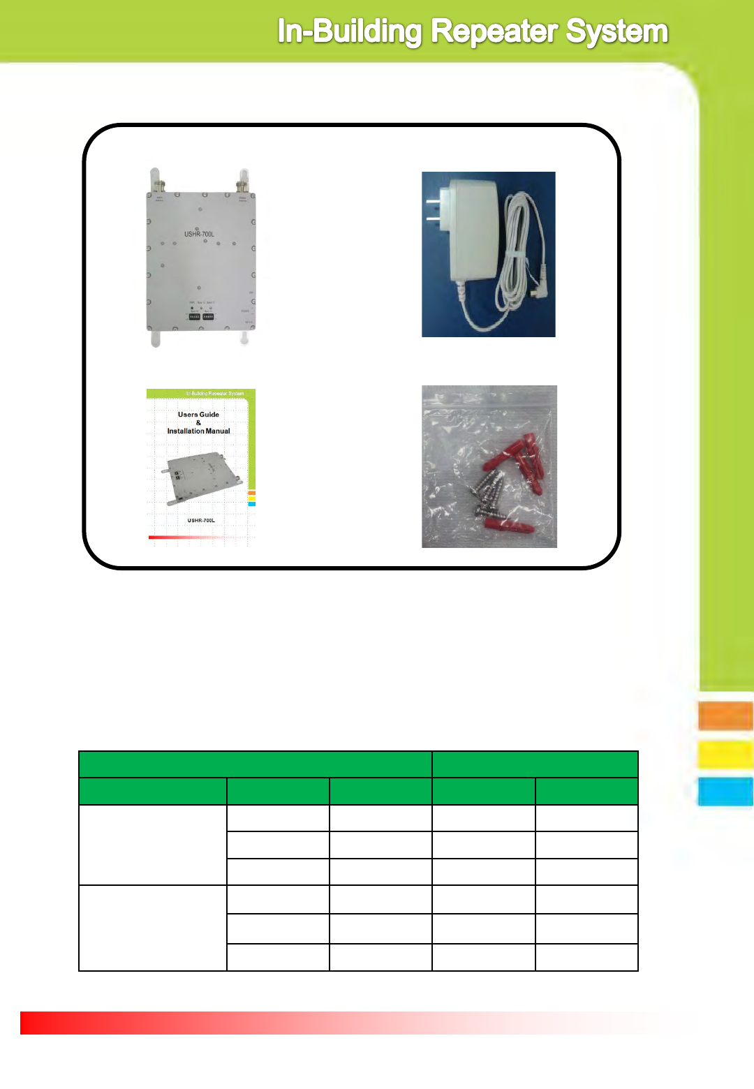
① Dual Band Repeater ② AC/DC Adapter
③ User Manual
2. System components
④ Installation bolts
① Dual band Repeater : BTS and mobile phone signal booster
② AC/DC Adaptor : 110VAC power supply
③ User Manual : Operation manual
④ Installation Bolts : Holds repeater on the vertical wall
● List of approved antennas & cables
Antenna RF Cable
Item Model Gain Model Cable type
Service Antenna
(Indoor Antenna)
PAT-CPWI-L +4dBi AC200000 LMR200
TS260771 +8dBi TS320000 RF240
TS250374 +5dBi TS340000 RF400
Donor Antenna
(Outdoor Antenna)
ALP-17QD-L +6dBi TS350000 ½”
TS210471 +4.5dBi TS360000 ½”
TS220971 +9dBi - -

Page 6
3.1.1. Install Donor Antenna on higher location to avoid any signal
interference. Mount towards to the BTS where a clear line-of-sight
path exists for optimal signal level.
3.1.2. Install service antenna at appropriate location such as wall or
roof ceiling. Make sure service antenna is not blocked by
furniture or hope appliance.
3.1.3. Use enclosed bolt to fix repeater on the wall and plug in power
adaptor.
3.1.4. For best optimal operation, antenna isolation (oscillation level) should be
set above minimum 15 dB gain. The industry standard for antenna to
antenna isolation formula is BDA gain + 15 dB.
Indoor Antenna
Out Door Antenna
Base satation
Service
Antenna
USHR-700L
BTS
Donor
Antenna
3.2. Repeater Outdoor
ANT Port
Indoor ANT
Port
Band 12
Status LED
POWER
LED
LTE Band12
Gain control
Dip Switch
LTE Band13
Gain control
Dip Switch
POWER Jack
Port
Power
ON/OFF
Switch
Band 13
Status LED
GUI
PORT
3. Installation
3.1. Installation diagram

Page 7
3.3. Repeater and Antenna connection
3.3.1. Connect donor antenna cable to outdoor antenna port as
shown below.
3.3.2. Connect Service antenna to indoor antenna port as shown below.
3.3.3. Plug in power adaptor to power outlet.

Page 8
3.3.4. Plug in AD/DC adaptor to connector listed as DC5.6V
3.3.5. Once power is on, it will show 3 green LED light on the front of
product as shown below.
LTE Band13
Gain manual control
Dip Switch (0~25dB)
LTE Band12
Gain manual control
Dip Switch (0~25dB)
3.3.6 The factory default set-up has both Automatic Attenuator Control (AAC)
& Automatic Level Control (ALC) pre-activated by USHR-700L Internal CPU.
All Isolation Check features can be manually adjusted via Dip switch using GUI
program (Repeater Control & Monitoring Software).
Page 9
4. Trouble Shooting
4.1. LED Status
4.1.1. Power on /off status.
4.1.1. Power on /off status.
4.1.2. Band 12 normal operation condition.
4.1.3. Band 12 detects excessive input signal and shut down.
4.1.4 Shut Down Algorithm status on BAND 12 Signal Input.
4.1.5. PATH OFF indicator during Uplink Sleep Mode for BAND 12.
4.1.6. Isolation SD Algorithm status on Band 12
4.1.7. Band 12 detects Insufficient Isolation between donor & service antenna and shut down.
4.1.8. Band 13 normal operation condition.
4.1.9. Band 13 detects excessive input signal and shut down.
4.1.10 Shut Down Algorithm status on BAND 13 Signal Input.
4.1.11. PATH OFF indicator during Uplink Sleep Mode for BAND 13.
4.1.12. PATH OFF indicator during Uplink Sleep Mode for BAND 12.
4.1.13. Band 12 detects Insufficient Isolation between donor & service antenna and shut down.
Item GREEN LED RED LED Reference
PWR
ON × See 4.1.1
OFF × See 4.1.1
LTE Band 12
ON - See 4.1.2
- ON See 4.1.3
Green Blinking per 1 sec cycle - See 4.1.4
Green Blinking per 5 sec cycle - See 4.1.5
- RED Blinking per 1 sec cycle See 4.1.6
RED Blinking per 5 sec cycle See 4.1.7
LTE Band 13
ON - See 4.1.8
- ON See 4.1.9
Green Blinking per 1 sec cycle - See 4.1.10
Green Blinking per 5 sec cycle - See 4.1.11
- RED Blinking per 1 sec cycle See 4.1.12
RED Blinking per 5 sec cycle See 4.1.13

Page 10
5. Specification
5.1. Electrical Specification
Item Specifications Note
Frequency Range
Down Link 728 ~ 746 MHz BAND12
Up Link 698 ~ 716 MHz
Down Link 746 ~ 757 MHz BAND13
Up Link 776 ~ 787 MHz
Modulation Type GSM. EDGE, CDMA, EVDO, HSPA, LTE
Input Power limit
Down Link -45dBm max BAND12
Up Link -13dBm max
Down Link -45dBm max BAND13
Up Link -13dBm max
Output Power
Down Link +2dBm @ booster output port LTE DL 5MHz 25RB
Up Link +22dBm @ booster output port LTE UL 5MHz 25RB
Down Link +2dBm @ booster output port LTE DL 5MHz 25RB
Up Link +22dBm @ booster output port LTE UL 5MHz 25RB
Gain
Down Link 47dB ~ 61dB (±1.0dB) BAND12
Up Link 35dB ~ 60dB (±1.0dB)
Down Link 47dB ~ 61dB (±1.0dB) BAND13
Up Link 35dB ~ 60dB (±1.0dB)
Ripple Down / Up Link < 4dB BAND12
Down / Up Link < 4dB BAND13
Noise Figure Down / Up Link < 6.0dB / < 6.0dB BAND12 Max Gain
Down / Up Link < 6.0dB / < 6.0dB BAND13 Max Gain
Noise Power Limit
Down Link < -70dBm/MHz On shutdown
Up Link < -70dBm/MHz On shutdown & sleep mode
Down / Up Link FCC BAND12
Down / Up Link FCC BAND13
Propagation Delay < 3us
VSWR ≤ 1.8 : 1
ALC Setting Level
Down Link(Upper Value) +2dBm±1.0dB
- ALC, SD, OSC functional opera
tion is completely separate BAN
D12 and BAND13.
Window Size(Lower Offset) 0 ~ 10dB
Up Link (Upper Value) +22dBm±1.0dB
Window Size(Lower Offset) 0 ~ 10dB
ALC Range Down Link ≤ 14dB
Up Link ≤ 25dB
Uplink Gain limit
DL starting input level
for Uplink Gain
Interlocking
-68 dBm
Shutdown Level Down Link > -45dBm/Total
Up Link > -13dBm/Total
OSC Level Down Link DL detects OSC under 1 sec.
Up Link UL detects OSC under 0.3 sec.
Uplink In-activity Up link On@ > -90dBm, OFF@ < -92dBm - No uplink signal for 5 minutes

Page 11
Gain
Control
Range
ALC
Down Link 0dB ~ 14dB / 1dB step @ Band12
- be controlled GUI or Dip Switch
- Total Atten control Range :
0dB ~ 25dB / 1dB Step
(Both DL and UL are the same)
Up Link 0dB ~ 25dB / 1dB step @ Band13
Dip Switch
Down link 0dB ~ 25dB / 1dB Step
Up link 0dB ~ 25dB / 1dB Step
Gain Control Deviation < ± 1dB
EVM < 7% No Feedback
ACLR (± 10MHz)
Down Link ≥ 38dB LTE DL 5MHz 25RB
Up Link ≥ 32dB LTE UL 5MHz 25RB
Isolation checking Range
47dB ~ 75dB / BAND12
Detecting deviation: < ±2.0dB
47dB ~ 75dB / BAND13
In band Spurious
(Operating band unwanted emissions) Category A 3GPP TS 36.106
Out Band Spurious
< -13dBm/1kHz RBW 9kHz ~ 150kHz
< -13dBm/10kHz RBW 150kHz ~ 30MHz
< -13dBm/100kHz RBW 30MHz ~ 1GHz
< -13dBm/1MHz RBW 1GHz ~ 12.75GHz
3rd IMD < -19dBm
Frequency Stability ≤ ±0.01ppm
GUI Interface RS-232C
Power Consumption < 15 W
Operating Power AC/DC Adapter(AC110V or AC220V)
RF Connector N-type Female
● Additional Information:
This repeater is a bi-directional amplifier for the boosting of cellular phone signals
and data communication devices.
The following frequency bands and emission types are utilized.
Frequency Band
Uplink 698 ~ 716 MHz 776 ~ 787 MHz
Downlink 728 ~ 746 MHz 746 ~ 757 MHz
Emission Designators
CDMA HSPA LTE EVDO EDGE GSM
F9W F9W G7D F9W G7W GXW

Page 11
Item Specifications Note
Dimensions (L × W × H) 151mm x 191mm x 35mm
(5.95 x 7.5 x 1.38 inch)
Weight < 2Kg
Item Specifications Note
Temperature -30 ~ 55℃(-22 ~ 131℉)
Humidity 10 ~ 95%
5.2. Mechanical Specification
5.3. Environment Specification
Items Specifications Note
AC input power 90VAC ~ 264VAC, 47Hz ~ 63Hz
Output rated Voltage +5.5VDC/1.3A
Voltage Current range 2.5A ~ 0.0 A
Operation Temperature -30℃ ~ +55℃
Operation humidity 10% ~ 90%
5.4. AC/DC Adaptor Specification
6. Certificates
6.1 FCC Certification
Model : USHR-700L
▪ Certificate Data :
▪ Certificate Number: