OPTOELECTRONICS CRD3301 Charging/Communication Cradle User Manual Users manual
OPTOELECTRONICS Co., Ltd. Charging/Communication Cradle Users manual
UserManual.wiki
>
OPTOELECTRONICS
>
CRD3301 User Manual
Users manual
Navigation menu
Upload a User Manual
Namespaces
Wiki Guide
HTML
PDF
Info
Views
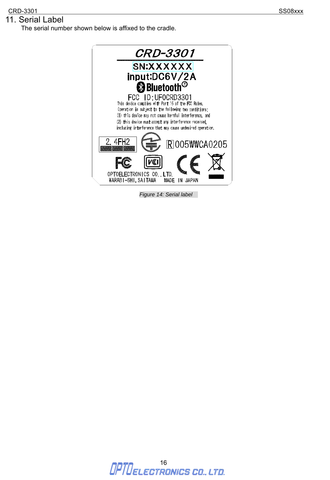
User Manual
Discussion / Help
Navigation

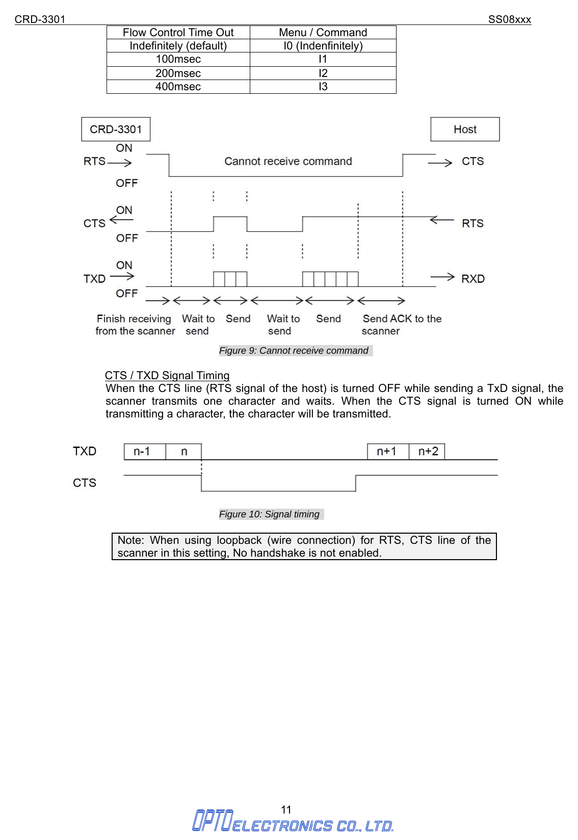
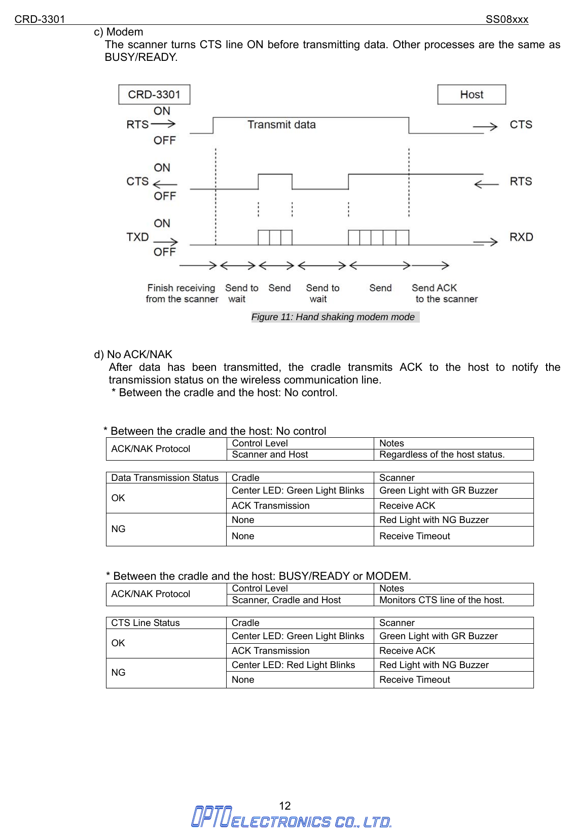
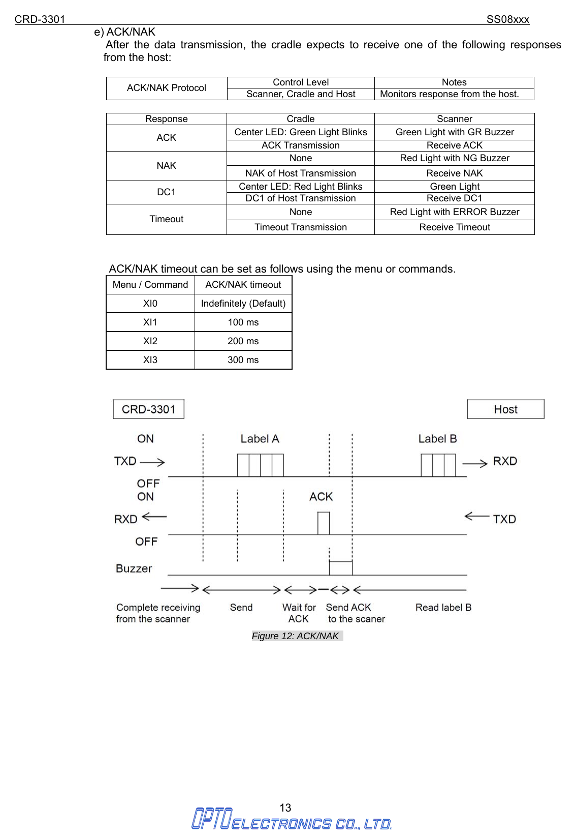

![CRD-3301 SS08xxx 22 Appendix. Mechanical Drawing Figure 17: Mechanical drawing of CRD-3301 [単位: mm]](https://usermanual.wiki/OPTOELECTRONICS/CRD3301/User-Guide-1083177-Page-25.png)