OPTOELECTRONICS CRD3301 Charging/Communication Cradle User Manual Users manual
OPTOELECTRONICS Co., Ltd. Charging/Communication Cradle Users manual
Users manual

CRD-3301 SS08xxx
Master Specifications
Charging / Communication Cradle
Product Name CRD-3301
Specification No T.B.D
Edition Initial
Date of Publication T.B.D
Original Doc. No. T.B.D
OPTOELECTRONICS Co., Ltd.
4-12-17 Tsukagoshi,
Warabi-shi, Saitama,
335-0002 Japan
TEL: 81+(0)48-446-1183
FAX: 81+(0)48-446-1184

CRD-3301 SS08xxx
Revision History
Specification No.: T.B.D
Product name : CRD-3301
Revision Date Section Description of Changes
Initial T.B.D - -

CRD-3301 SS08xxx
Table of contents
1. Abstract ·····································································································1
2. Overview ···································································································1
3. Basic Specifications···················································································2
4. Bluetooth ···································································································4
5. Detailed View·····························································································5
6. Electrical Specifications ·············································································6
7. DIPSW configurations ···············································································7
8. Cable Interface ··························································································8
9. Interface Cable ························································································15
10. Default Setting ·······················································································15
11. Serial Label····························································································16
12. Packaging Specifications·······································································17
13. Environmental Specifications·································································17
14. Reliability ·······························································································18
15. Warranty ································································································18
16. Regulatory Compliance ·········································································19
17. RoHS·····································································································20
18. Precautions ···························································································20
19. Bluetooth ·······························································································21
20. Frequency Band ····················································································21
Appendix. Mechanical Drawing ···································································22

CRD-3301 SS08xxx
1
1. Abstract
This manual provides the specifications for the charging / communication cradle, CRD-3301.
2. Overview
CRD-3301 is the dedicated charging / communication cradle for the laser handy scanner, OPR-3301.
Followings are the features of the CRD-3301:
・ CRD-3301 receives data from OPR-3301 via ver.2 compliant Bluetooth interface.
・ The cradle can output the received data via RS232C or USB interface.
・ OPR-3301 can be charged by placing it on the CRD-3301.
・ RoHS – CRD-3301 is compliant with RoHS.
(However, it is assessed by Optoelectronics Co., Ltd. and it does not have any legal weight in the EU.)
CRD-3301 SS08xxx
2
3. Basic Specifications
Item Specification Remark
CPU 16bit CMOS CPU
Clock frequency 12.00MHz
Control Section
FLASH ROM 256KB For BIOS/DATA
RS-232C: 600bps to 57.6kbps
Communication Section
Interface
USB: 2.0 HID compliant
Frequency 2400MHz to 2483.5MHz
Specification Bluetooth Ver2.0 compliant Installed SPP
Transmission power Class 2 (4dBm or less)
Communication range 10m
The distance may vary
depending on the
environment.
Baud rate 57.6kbps
Wireless section
Antenna 1/4λ (surface mounted)
Indication
LED Power: red (far left)
Power feeding Section
For charging a scanner Output: DC6V (typ.)
Terminal: +/-/ Power supply control
Operation voltage range 5.7 to 6.3V Dedicated AC adapter:
6.0V±5%
Standby 90mA or less Without charging
Main power section
Consumption
current
Max. 1000mA With charging
CRD-3301 SS08xxx
3
Operation 0 to 40%
Temperature Storage -20 to 60%
Operation 25 to 85% No frost, no condensation
Humidity Storage 20 to 90% No frost, no condensation
Frequency
Increased the frequency of vibration from 10Hz to 100Hz
at an accelerated velocity of 19.6m/s2 (2G) for 6 minutes
each in X-direction, Y-direction and Z-direction. Repeated
this test for 10 times in each direction.
Drop test
Dropped from a height of 75cm onto a concrete surface.
The drop test is done for each side (right, left, front, back,
top and bottom).
Environment specifications
Drip proof Not tested
EMI/RFI VCCI/EN55022/FCC Part15, B For residential, commercial and
light-industrial environments
CE marking
Product safety
IEC/EN 60950-1
Regulatory compliance
EMC EN55024 (EN61000-6-1) Class-B For residential, commercial and
light-industrial environments
No
destruction
Air discharge: 15kV
(Impressed static electricity of 15kVfor 50
times on the surface of the scanner)
Resistance to static
electricity No
malfunction
Contact discharge (direct/indirect): ±8kV
Air discharge (direct) : ±8kV
Condition:
IEC61000-4-2 compliant
Voltage Alternating-current Input Cable: ± 1kV
Pulse 5/50ns (Tr/Tw)
Fast Transient
Frequency 5kHz
Condition:
IEC61000-4-4 compliant
Pulse 1.2/50μs (Tr/Th)
From L to P:± 2 kV (closed-loop voltage)
Surge Voltage From L to L:± 1 kV (closed-loop voltage)
Condition:
IEC61000-4-5 compliant
Frequency 50, 60Hz Power supply frequency
magnetic field Level 3A/m
Condition:
IEC61000-4-8 compliant
Dip 1 Drop 30%, 0.5 cycles
Dip 2 Drop 60%, 5cyccles
Immunity test
Voltage dip, momentary
voltage drop, etc. Momentary
drop > Drop 95% ,250 Cycles
Condition:
IEC61000-4-11 compliant
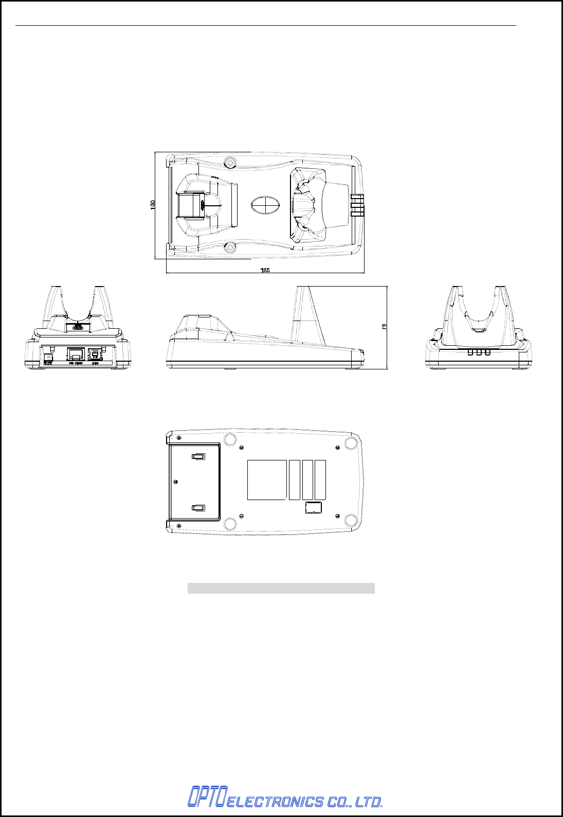
Dimensions Approx. 100 (W) × 185 (D) × 78 (H)
Physical features
Weight
250g (max.) Excluding the AC adapter
Model name SFP0602000P-PSE (Integrated plug)
Voltage range AC 90 to 264V
Input Supply current 0.5A max
Voltage range 5.7 to 6.3V
AC ad
apter
Output
Maximum current 2A max
* This chart contains the sections which state about the combination of CRD-3301 and OPR-3301.

CRD-3301 SS08xxx
4
4. Bluetooth
CRD-3301 uses Bluetooth as a wireless interface.
Blue tooth is compliant with ver.2.0 and supports SPP (Serial Port Profile).
・ Supported Protocol Stack
- RF (Radio Frequency Protocol)
- BB (Base Band Protocol)
- LM (Link Manager Protocol)
- L2CAP (Logical Link Control and Adaptation Protocol)
- SDP (Service Discovery Protocol)
- RFCOMM (emulation for RS-232C)
・ Supported Profile
- GAP (Generic Access Profile)
- SPP (Serial Port Profile)
・ Communication Configuration
1 to 1
One scanner to one host system
・ Scanner operating mode while connected to the host system
- Scanner (OPR-3301): Master mode
- Cradle (CRD-3301): Slave mode
・ Security Mode
Authentication enabled
・ Encryption
Encryption enabled
CRD-3301 SS08xxx
5
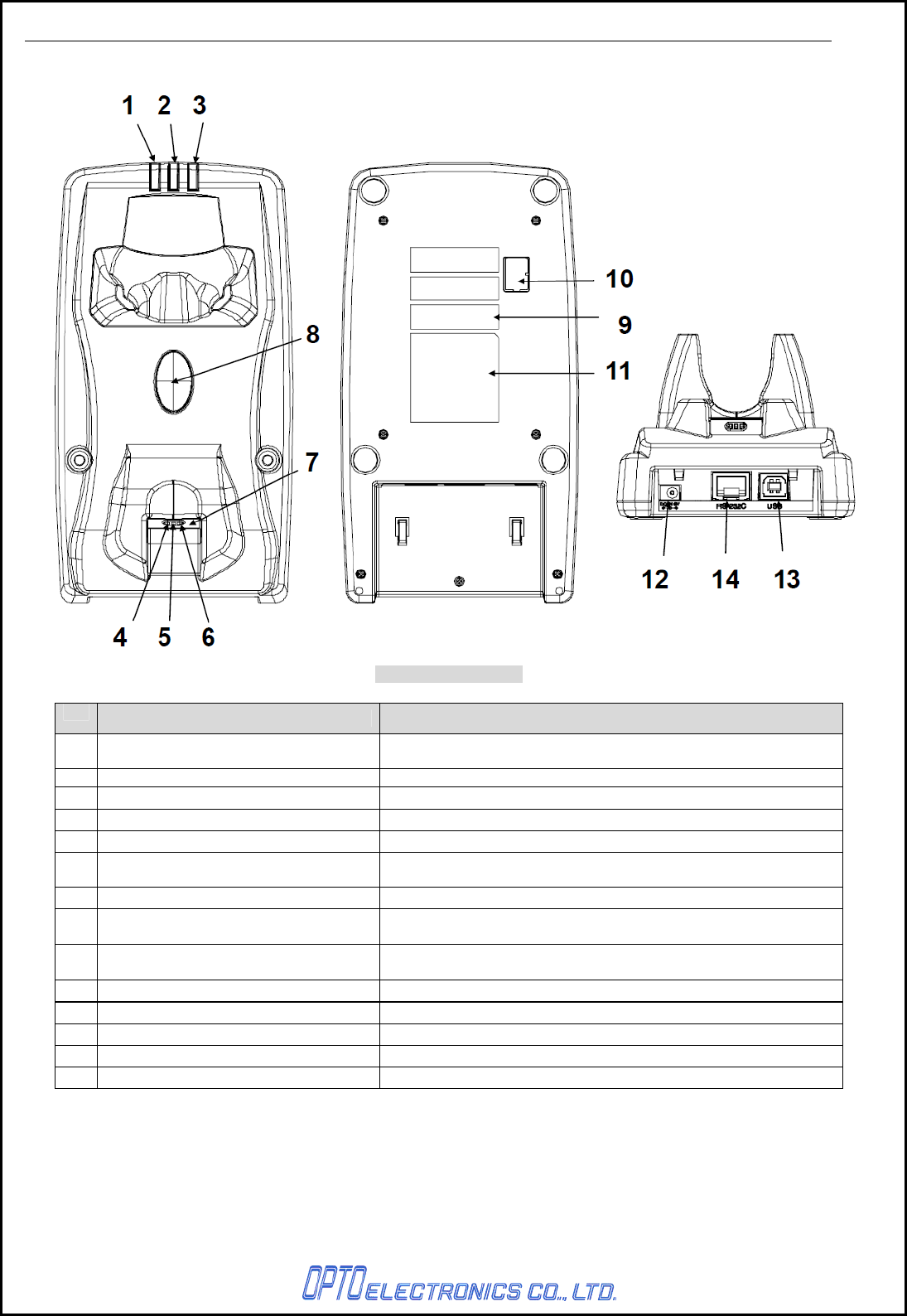
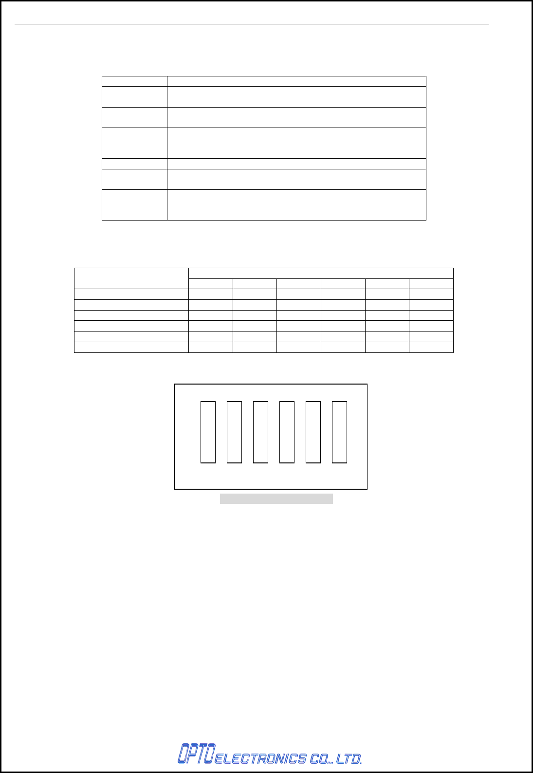
5. Detailed View
Figure1: Detailed view
No. Items Specifications
1 Wireless communication status LED Indicates operational status such as whether Bluetooth
communication is connected.
2 Communication status LED LED to indicate the interface and data transmission status.
3 Power Supply Status LED LED to indicate the power supply status
4 Power supply terminal (-) Negative power supply terminal for the scanner (OPR-3301).
5 Power supply terminal (+) Positive power supply terminal for the cradle (OPR-3301).
6 Scanner control terminal Terminal to transfer the kind of power (AC adapter / USB bus
power).
7 Scanner detection switch Switch to detect if the scanner (OPR-3301) is set on the cradle.
8 Scanner search button Press the button when the scanner is missing. As long as the
connection is established, the scanner answers via buzzer.
9 Barcode for BD address setting Scan the barcode with the scanner(OPR-3301) to set the
connection.
10 Dip switch Dip switch for function settings
11 Serial label -
12 DC Jack Power supply jack for the dedicated AC adapter.
13 USB connector USB connector for the USB interface cable.
14 Modular jack Connector for the RS232C interface cable.
CRD-3301 SS08xxx
6
6. Electrical Specifications
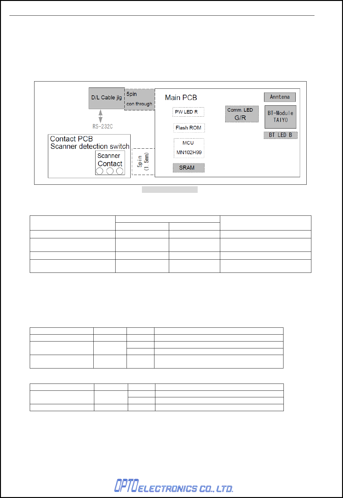
6.1. Configurations of CRD-3301
CRD-3301 is the dedicated cradle for OPR-3301 scanner which is able to charge and communicate with
the scanner. This product consists of a power supply section which uses Bluetooth interface, power
section which is in charge of power feed and voltage conversion for the scanner.
CRD-3301 can be operated by AC adapter or USB bus power, however, AC adapter is prior to USB bus
power and USB power is disabled in the scanner when both power supplies are used at the same time.
Figure2: Detailed view
6.2. Consumption Current
Specifications
Item RS-232C USB* Conditions
When stand-by 90mA or less 90mA or less Bluetooth communication: OFF
When communicating with a
host computer 120mA or les 120mA or less Bluetooth communication: ON
When charging a scanner 1000mA or less 500mA or less Bluetooth communication: ON
Measurement conditions:
Power supply voltage 6.0V 5V
* Followings cannot be used as power supply and AC adapter needs to be used.
・ The maximum current of USB interface is 100mA.
・ The device which maximum current is 500mA, however, it uses USB hub.
6.3. LED Indication
These LEDs shown below notify operational status.
LED Location Color Function
Power LED Far left Red Lights when power ON.
Green Lights during data transmission.
Communication LED Middle Red Lights during data reception.
Wireless LED Far right Blue Lights when Bluetooth succeeds in connection.
Blinks when Bluetooth fails in connection.
LED blinking cycle
LED Location Color blinking cycle
Green 200mS
Communication LED Middle Red 500mS
Wireless LED Far right Blue 500mS
CRD-3301 SS08xxx
7
7. DIPSW configurations
Following functions can be set by DIPSW as shown.
DIPSW No. Function
DIPSW1 Make sure the it is always OFF when using the cradle.
This will be used for feature expansion.
DIPSW2 Enables inquiry scan withiout security
Connection can be made witout authentication.
DIPSW3 Disables protocol while in connection.
The menu allows the cradle to connect to bluetooth devices
including OPR-3301.
DIPSW4 Disable DTR signakl detection for the host.
DIPSW5 Sets the cradle to the default.
(Sets the contents of FLAH ROM to the initial setting.)
DIPSW6 It is normally OFF.
When it is ON, *“software update mode” operates
* With in this mode, software is rewitten via RS232C interface.
Note: 1. All DIPSWs are available when power ON.
2. In the default setting, SW6 is ON, rest of them are OFF.
How to set DIPSW
DIPSW
Setting SW1 SW2 SW3 SW4 SW5 SW6
N/A X X X X OFF OFF
NO SECURITY X ON X X OFF OFF
NO PROTOCOL X X ON X OFF OFF
IGNORE DTR X X X ON OFF OFF
INITIAL SETUP X X X X ON OFF
DOWNLOAD MODE X X X X X ON
X : Don’t Care
Figure3: Location of DIPSW
1 2 3 4 5 6
ON
CRD-3301 SS08xxx
8
8. Cable Interface
CRD-3301 supports RS232C and USB HID interfaces.
The cradle recognizes the interface whilst watching its power supply.
* When changing an interface, turn OFF the power and change the setting for access point of the scanner
and read the BD address. Otherwise it may cause malfunctions such as connection and data
transmission failure.
8.1. RS232C Interface
8.1.1. Signal Level
RS-232C Level (V)
Signal name IN/OUT Mark/OFF Space/ON
TXD OUT -5 to15 +5 to +15
RXD IN -3 to15 +3 to +15
RTS OUT -5 to -15 +5 to +15
CTS IN -3 to -15 +3 to +15
DSR IN -3 to -15 +3 to +15
8.1.2. Signal Level
PIN NO. Signal name Remark
1 RTS Flow control output
2 CTS Flow control input
3 TXD Transmission data to host
4 RXD Transmission data from host
5 NC Not connected
6 GND
7 NC Not connected
8 DSR For detecting interface connection
9 NC Not connected
10 NC Not connected
- FG
8.1.3. Connector Used
10-pin, modular jack
CRD-3301 SS08xxx
9
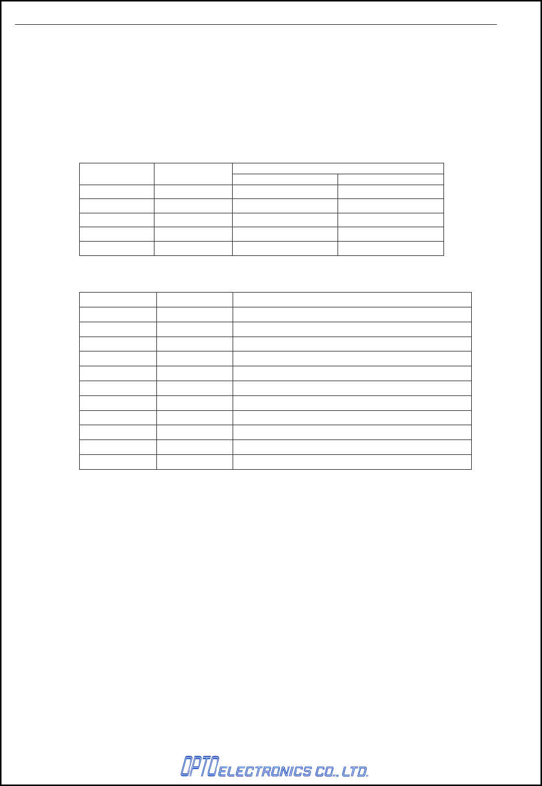
8.1.4. Interface Circuit
Figure4: Interface circuit
8.1.5. Character Format
Figure5: Character format
8.1.6. Communication Format
Figure6: Communication format
8.1.7. Communication Control
By reading menus listed below enables the cradle to communicate with host computer.
Settings information is sent from the scanner.
BUSY/READY and P5 are set as default.
Handshaking Menu / command
No hand shake P0
Busy/Ready P1
Modem P2
ACK/NAK P3
ACK/NAK No response P4
CRD-3301 SS08xxx
10
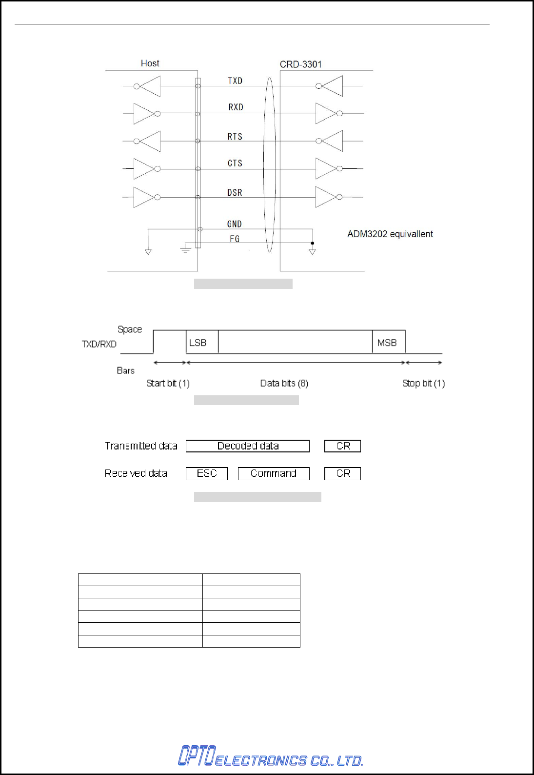
a) No hand shaking
The scanner attempts the communication regardless of the state of the host computer.
Flow control is not executed for the Bluetooth interface. For the scanner (OPR-3301),
RTS is always enabled.
Figure7: No Handshaking
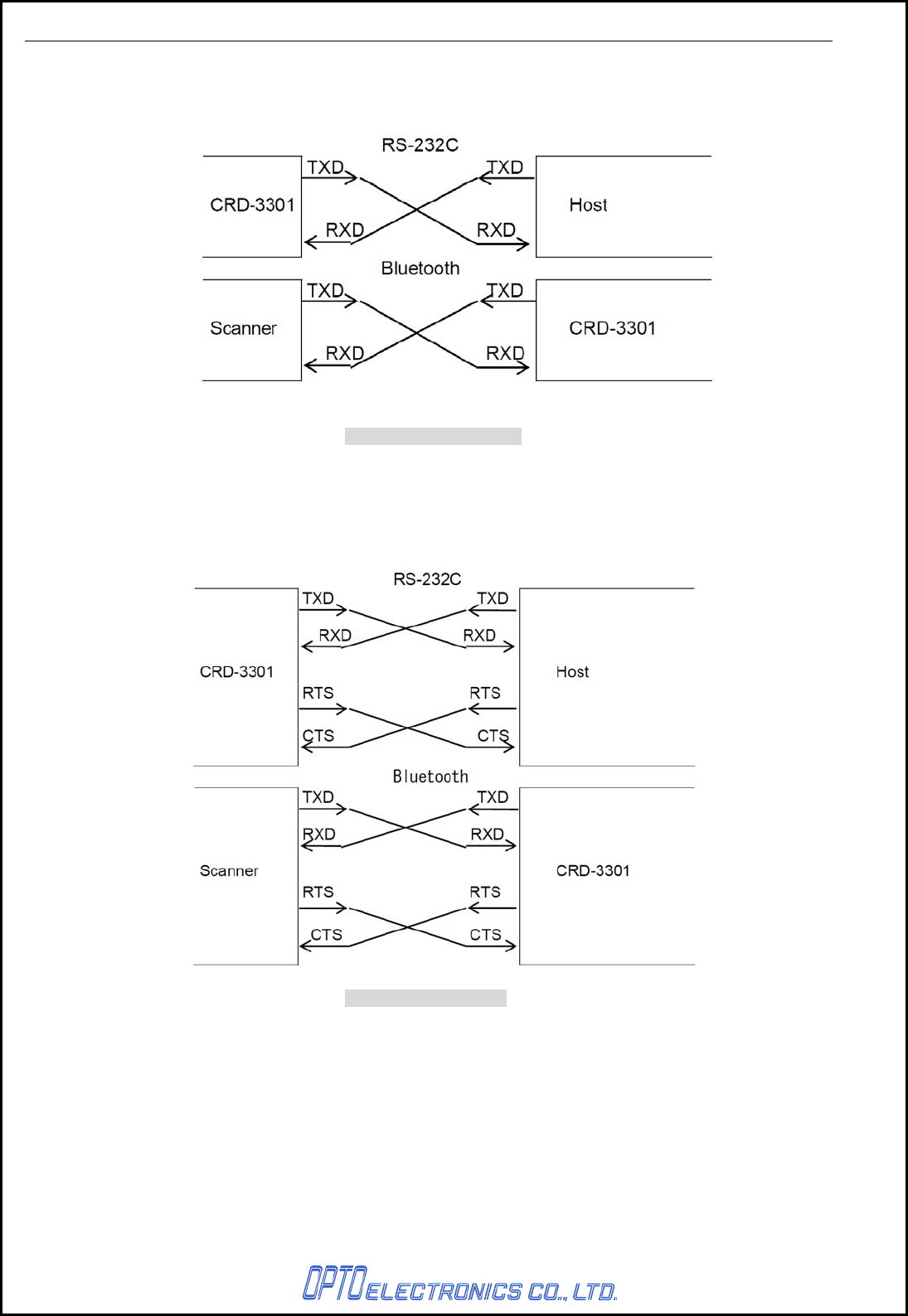
b) BUSY/READY
The scanner and the host computer notify each other of their state and whether they can
receive data with BUSY/READY through an RTS line. They can communicate state to each
other through a CTS line when connected as in the following figure.
Flow control is executed for the Bluetooth interface.
Figure8: BUSY/READY
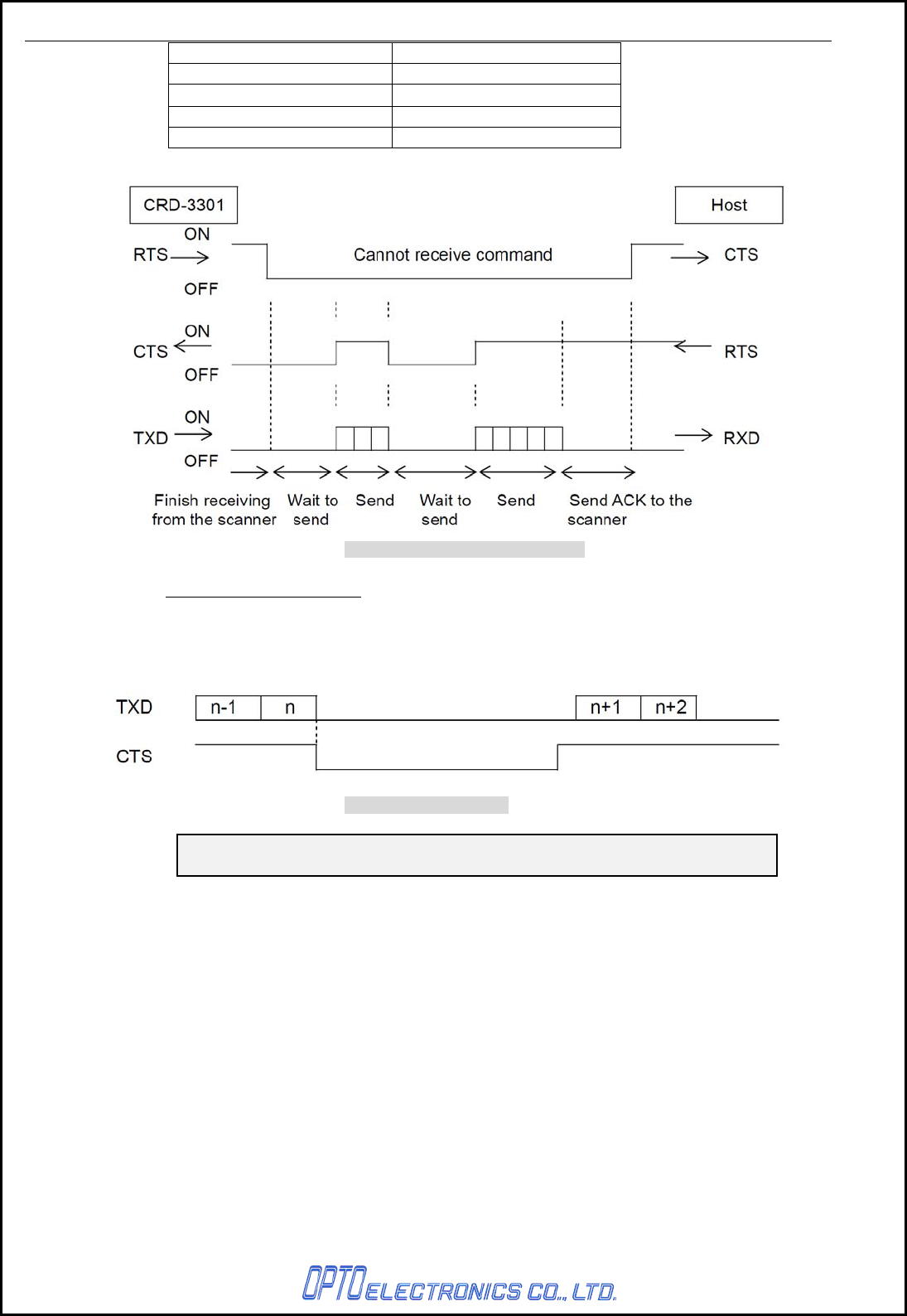
The cradle stays ON (is able to receive data) except while it is transmitting data via IrDA or
RS-232C interfaces. The cradle checks the CTS line before transmitting data. When it is ON,
the cradle transmits data. When it is OFF, the cradle waits for it to turn ON within a set time.
When the CTS line is not ON within a specified period, the cradle will blink the red LED to
indicate it. The Flow Control timeouts are as follows, and the default setting is
“indefinitely“ (I0).
CRD-3301 SS08xxx
11
Flow Control Time Out Menu / Command
Indefinitely (default) I0 (Indenfinitely)
100msec I1
200msec I2
400msec I3
Figure 9: Cannot receive command
CTS / TXD Signal Timing
When the CTS line (RTS signal of the host) is turned OFF while sending a TxD signal, the
scanner transmits one character and waits. When the CTS signal is turned ON while
transmitting a character, the character will be transmitted.
Figure 10: Signal timing
Note: When using loopback (wire connection) for RTS, CTS line of the
scanner in this setting, No handshake is not enabled.
CRD-3301 SS08xxx
12
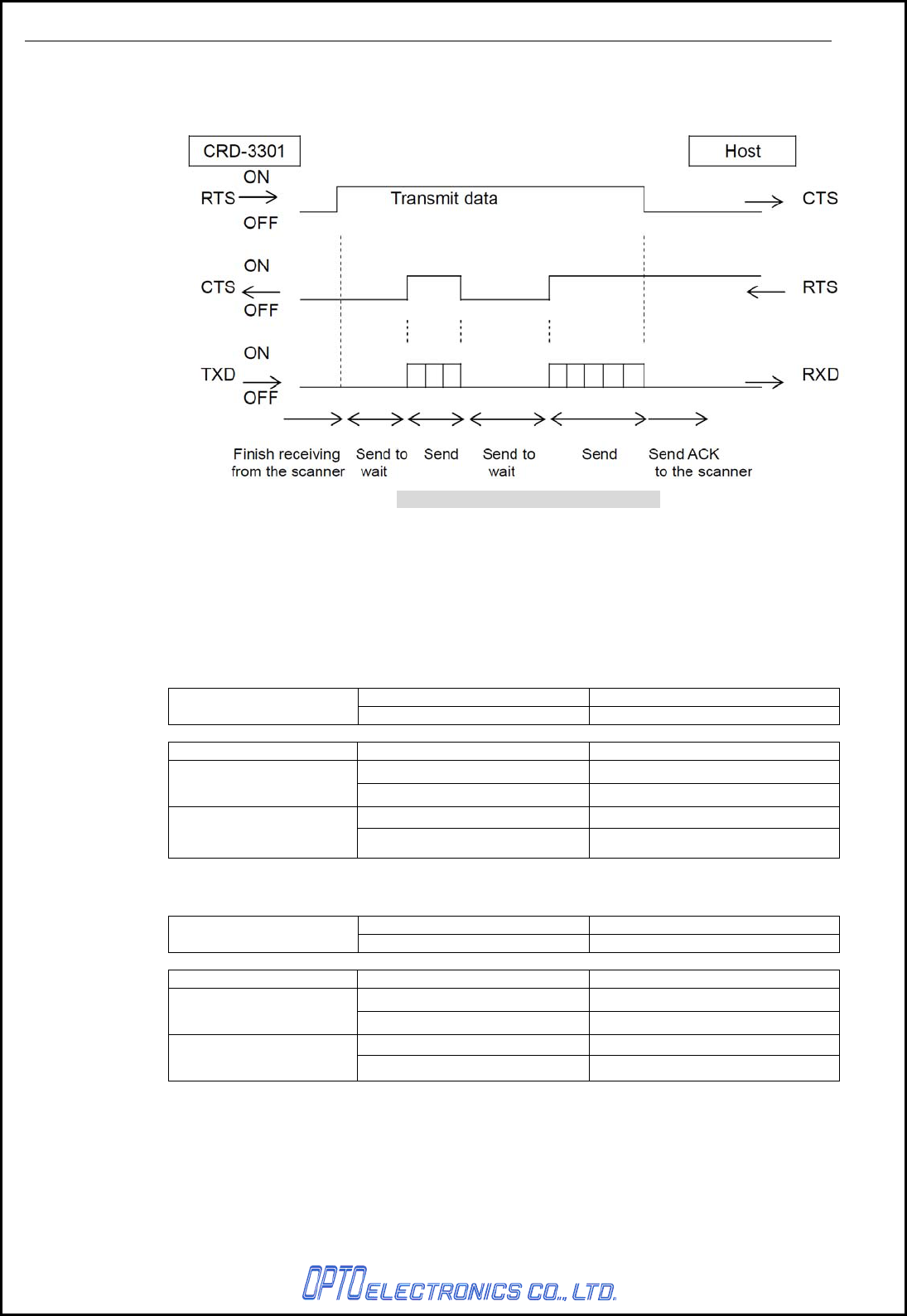
c) Modem
The scanner turns CTS line ON before transmitting data. Other processes are the same as
BUSY/READY.
Figure 11: Hand shaking modem mode
d) No ACK/NAK
After data has been transmitted, the cradle transmits ACK to the host to notify the
transmission status on the wireless communication line.
* Between the cradle and the host: No control.
* Between the cradle and the host: No control
Control Level Notes
ACK/NAK Protocol Scanner and Host Regardless of the host status.
Data Transmission Status Cradle Scanner
Center LED: Green Light Blinks Green Light with GR Buzzer
OK ACK Transmission Receive ACK
None Red Light with NG Buzzer
NG None Receive Timeout
* Between the cradle and the host: BUSY/READY or MODEM.
Control Level Notes
ACK/NAK Protocol Scanner, Cradle and Host Monitors CTS line of the host.
CTS Line Status Cradle Scanner
Center LED: Green Light Blinks Green Light with GR Buzzer
OK ACK Transmission Receive ACK
Center LED: Red Light Blinks Red Light with NG Buzzer
NG None Receive Timeout
CRD-3301 SS08xxx
13
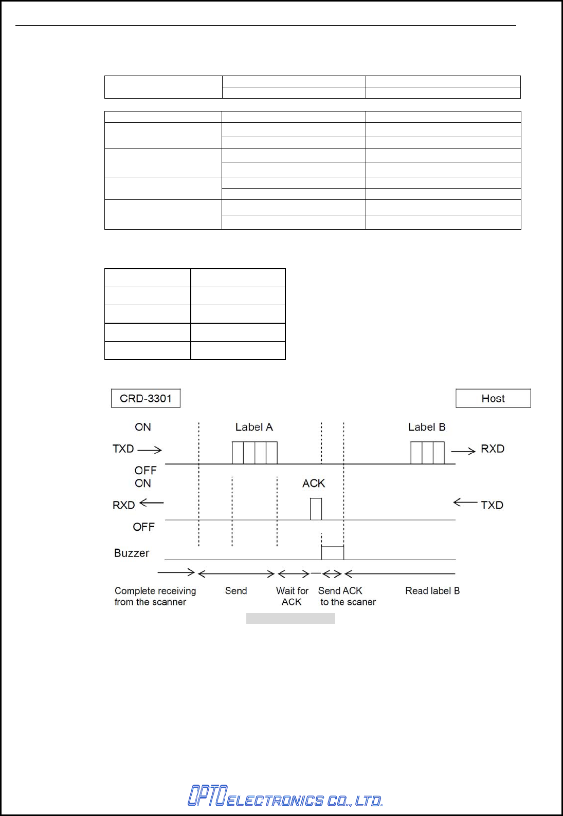
e) ACK/NAK
After the data transmission, the cradle expects to receive one of the following responses
from the host:
Control Level Notes
ACK/NAK Protocol Scanner, Cradle and Host Monitors response from the host.
Response Cradle Scanner
Center LED: Green Light Blinks Green Light with GR Buzzer
ACK ACK Transmission Receive ACK
None Red Light with NG Buzzer
NAK NAK of Host Transmission Receive NAK
Center LED: Red Light Blinks Green Light
DC1 DC1 of Host Transmission Receive DC1
None Red Light with ERROR Buzzer
Timeout Timeout Transmission Receive Timeout
ACK/NAK timeout can be set as follows using the menu or commands.
Menu / Command ACK/NAK timeout
XI0 Indefinitely (Default)
XI1 100 ms
XI2 200 ms
XI3 300 ms
Figure 12: ACK/NAK
CRD-3301 SS08xxx
14
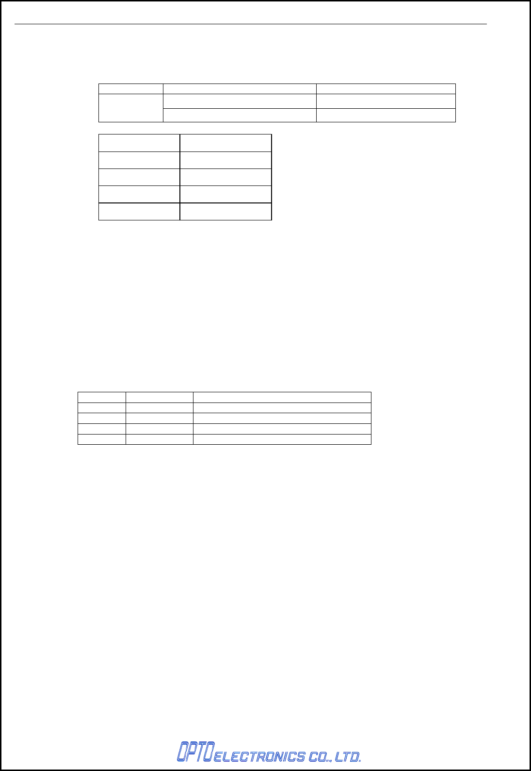
f) ACK/NAK NO RESPONSE
When no response from the host is received within the set time, the cradle assumes an ACK
response, and returns to the initial state without the error buzzer. The other actions are the
same as ACK/NAK.
Response Cradle Scanner
None Green Light with GR Buzzer
Timeout None Receive Timeout
Menu / Command Menu / Command
XI4 Indefinitely
XI5 100 ms (default)
XI6 500 ms
XI7 1000 ms
8.1.8. Baud Rate Setting
Receive baud rate setting information from the scanner and configure the settings.
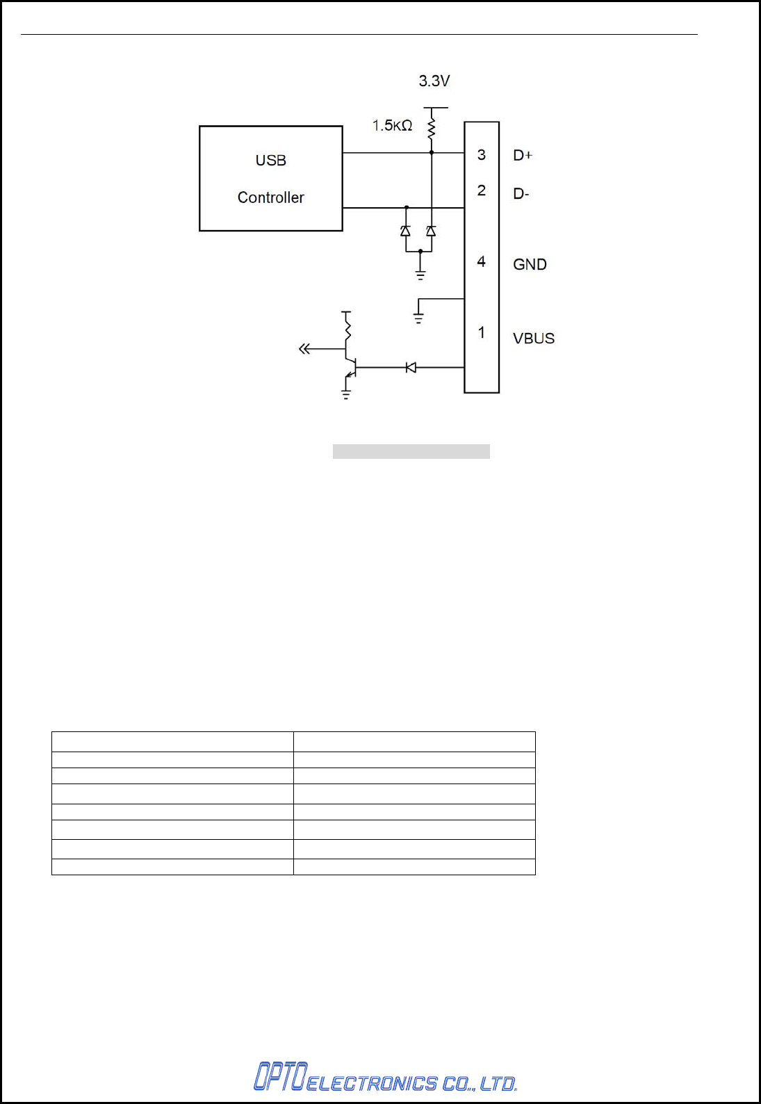
8.2. USA Interface
8.2.1. Specifiacation
USB2.0 HID Compliant
8.2.2. Connector
USB type B connector
8.2.3. Pin Assignment
Pin No. Signal name Note
1 VBUS Interface detection
2 D-
3 D+
4 GND
CRD-3301 SS08xxx
15
8.2.4. Interface Circuit
Figure 13: Interface circuit
9. Interface Cable
Both a RS232C cable and a USB cable are included for a package.
9.1. RS232C Cable
A dedicated RS-232C cable is packaged in a box with CRD-7734.
Cable model no.: B04009-05
9.2. USB Cable
Cable model no.: B03006-11
10. Default Setting
CRD-3301 is shipped with the following default settings (DIPSW5):
Default Setting
Parameter Setting
Baud Rate 9600 bps
Data Bit Length 8 bits
Party Bit No parity
Stop Bit 1 stop bit
Handshake BUSY/READY
ACK/NAK No ACK/NAC
CTS Timeout Indefinitely
CRD-3301 SS08xxx
16
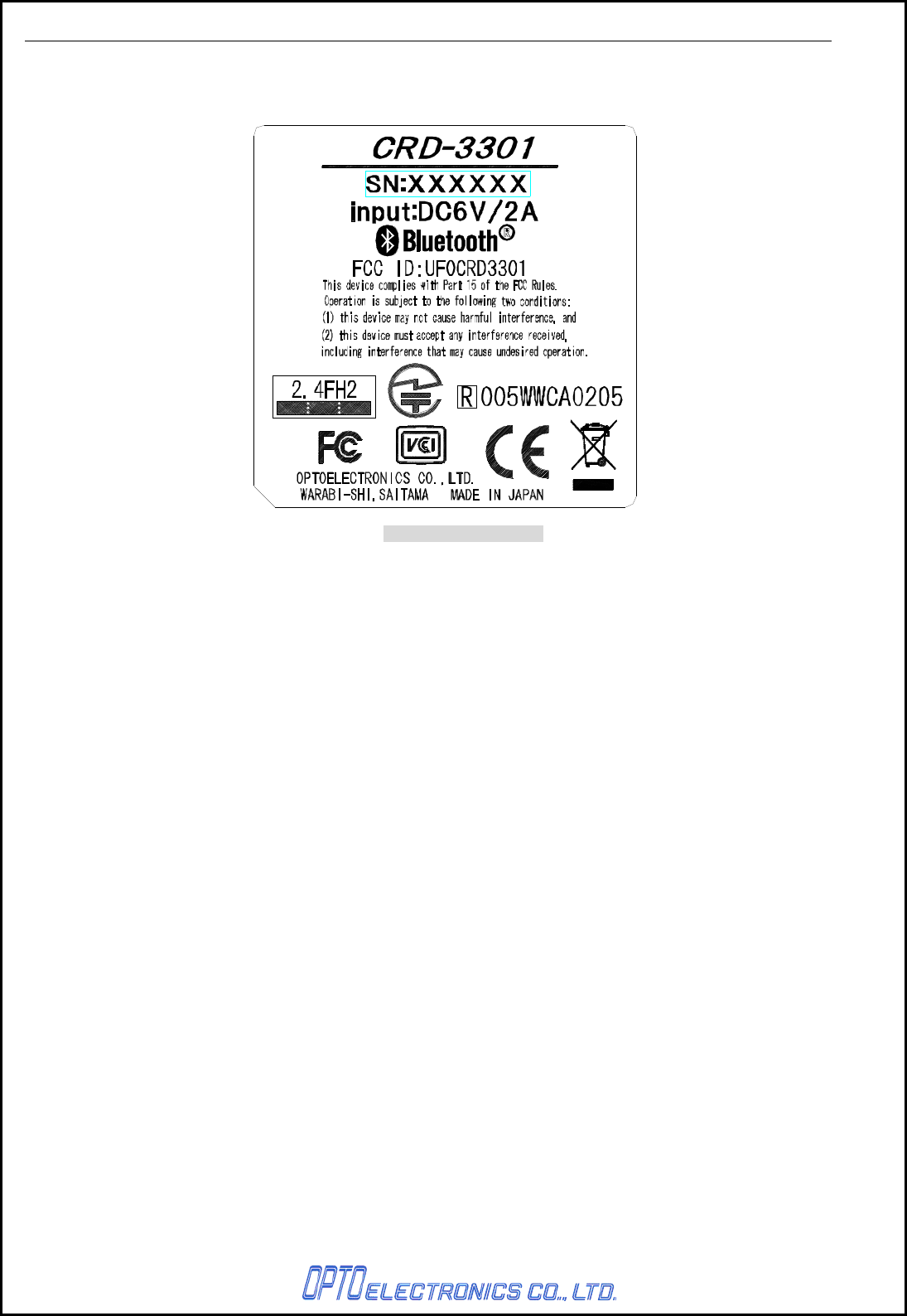
11. Serial Label
The serial number shown below is affixed to the cradle.
Figure 14: Serial label

CRD-3301 SS08xxx
17
12. Packaging Specifications
12.1. Individual Packaging Specufuactions
Size of the package: 163 (W) × 252 (D) × 123 (H) (mm)
*T.B.D
Figure 15: Individual packaging specifications
12.2. Collective Packaging Specufuactions
Size of the package: 260 (W) × 830 (D) × 255 (H) (mm)
*T.B.D Figure 16: Collective packaging specifications
Note: The “RO” mark labeled on the package tray or package box guarantees that the applicable product
has passed our test of RoHS restrictions compliance (the restriction of the use of certain
hazardous substances in electrical and electronic equipment, 2002/95 EC). However, this
document does not have any legal weight in the European Union.
13. Environmental Specifications
13.1. Operating Temperature and Humidity
Operating temperature: 0 to 40° C (Excluding AC adapter)
humidity: -25 to RH (No condensation, no frost)
13.2. Storage Temperature and Humidity
Storage temperature: -20 to 60° C
humidity: 20 to 90% RH
13.3. Electrical Specifications
・ Withstand voltage: AC 1500V / 60 seconds 10mA or less
・ Insulation resistance: DC500V 2MΩ
・ Leak current: 250μA or less / AC 250V 60Hz
・ Line noise: ±1kV or higher
・ Static noise: No destruction: ±15KV (air discharge, direct)
No malfunction: ±8kV (air discharge, direct)
±8kV (air discharge, direct)
*Measurement environment: Use electrostatic testing device compliant with IEC 61000-4-2.
(150pF, 330Ω)
13.4. Drop Test (without packaging)
No malfunction occurred after the following drop test.
Drop Test: Drop the scanner from a height of 75 cm onto a concrete floor.
(three times in each of 6 angles).
13.5. Drop Test (with individual packaging)
No malfunction occurred after the following drop test.
Drop Test: Drop an individually packaged scanner from a height of 75 cm onto a concrete floor once
on its 1 corner, 3 edges, and 6 sides (10 total drop tests).
13.6. Vibration Strength
No malfunction occurred after the following vibration test.

CRD-3301 SS08xxx
18
Vibration test: Increase the frequency of the vibration from 10 Hz to 100 Hz with accelerated velocity
19.6 m/s2 (2 G) for 60 minutes in non-operating state. Repeat this routine in each X, Y, Z direction
once for 60 minutes each.
14. Reliability
Parameter Tested Parts Life
MTBF Current-carrying parts 7 years
Number of Contact Power supply terminal 1,000,000 times
Number of operation Lever switch 100,000 times
15. Warranty
15.1. Warranty Period
OPTOELECTRONICS Co., Ltd. warrants that this product is free of defects or malfunctions for a
period of twelve (12) months from its shipment. In case of having defects or malfunctions caused by
normal usage in accordance with this specification during the foregoing warranty period,
OPTOELECTRONICS shall repair or adjust the product free of charge.
Any repair or replacement of the product after the foregoing warranty period shall be charged at
regular repair rates.
If defects or malfunctions were caused by customer mishandling, product repairs or replacement will
be charged at regular repair rates, even during the foregoing warranty periOD.
15.2. Delivery
Products for maintenance or repair shall be sent back to OPTOELECTRONICS. The sender is
responsible for all shipping costs.
15.3. Repair Time Frame
Repaired products shall be shipped back to the customer within 20 days after acceptance by
OPTOELECTRONICS.
Expedited repairs may be available, subject to terms agreed to by OPTOELECTRONICS and the
customer.
15.4. Repair Time Frame
The maintenance period of this product is 5 years after its shipment.
OPTOELECTRONICS may discontinue maintenance for this product during the 5-year maintenance
period if a satisfactory replacement product or maintenance solution is agreed to.
15.5. Others
Any additional warranty issues must be discussed with OPTOELECTRONICS on a case-by-case
basis.

CRD-3301 SS08xxx
20
17. RoHS
RoHS: The restriction of the use of certain hazardous substances in electrical and electronic equipment,
2002/95 EC.
18. Precautions
18.1. Radio Low
The data collector has obtained the Certification for Construction Design of Specified Radio
Equipment.
Therefore it does not need to have a radio station license in Japan.
The following activities are prohibited under the Radio Law:
• Remodeling and disassembly
• Peeling off the certificate label
Do NOT use the data collector under the following environment:
*Otherwise radio interference may affect other device and end up with causing physical or material
damage.
• Safety apparatus and medical device for human body protection
• Environment where is concerned to cause serious damage
18.2. HANDLING
Handle this product carefully. Do not deliberately subject it to any of the following.
(1) Shock
・Do not drop from the non-standard height.
・Do not place any heavy items on the data collector.
・Do not squeeze it between any heavy items.
・Do not swing around the cable.
(2) Temperature Conditions
・Do not use the data collector at temperatures outside the specified range.
・Do not pour boiling water on the data collector.
・Do not throw the data collector into the fire.
(3) Foreign Materials
・Do not put the data collector into liquid.
・Do not put the data collector into chemicals.
(4) Others
・Do not disassemble this product.
・Do not use the data collector near a radio or a TV receiver. It may cause reception problems.
・The data collector may be damaged by voltage drops caused by lightning.
・The data collector may not perform properly in environments when placed near a flickering light,
such as a CRT
18.3. Export Administration Regulations
This product is subject to the strategically controlled exports regulated under “Foreign Exchange and
Foreign Trade Laws”. Therefore, export of this product may require an export permission of
Japanese government.

CRD-3301 SS08xxx
21
19. Bluetooth
To communicate via Bluetooth, the device which CRD-3301 is connected to must support the same
Bluetooth version and profile as CRD-3301’s.
・ CRD-3301 is compliant to Bluetooth standards. However, we cannot assure the connection
between CRD-3301 and other Bluetooth devices which have not been tested.
・ Bluetooth supporting devices use 2.4 GHz frequency band. However, many other sorts of devices also
utilize this frequency band. It may effect the communication speed or communication range of this data
collector.
・ The use of CRD-3301 outside of the European Union, the United States and Canada is punishable
under the law.
・ Communication speed and communication range of CRD-3301 may differ due to the obstacles and
radio wave conditions between CRD-3301 and the device, which CRD-3301 is connected to.
・ Conditions of the device, which CRD-3301 is connected to, may also affect the communication speed
and communication range of CRD-3301.
20. Frequency Band
The frequency band 2.4 GHz is utilized by this scanner. Read carefully the followings before using this
product.
In the frequency band of this scanner, scientific, medical and industrial devices including microwaves are
used. Also other radio stations including local private radio station for mobile object identification requiring
license for such as manufacturing lines at factories, specific power-saving radio station requiring no
license and amateur radio station are managed.
Please make sure that “other radio stations” are not managed in the frequency band 2.4 GHz before using
this scanner.
In case that radio interference occurs between this scanner and “other radio stations,” change the service
space immediately, or stop transmitting radio wave to avoid the interference.
If you have any questions or troubles, please contact our marketing group.
CRD-3301 SS08xxx
22
Appendix. Mechanical Drawing
Figure 17: Mechanical drawing of CRD-3301
[単位: mm]